EP4245541A2 - Servovalves - Google Patents
Servovalves Download PDFInfo
- Publication number
- EP4245541A2 EP4245541A2 EP23186233.5A EP23186233A EP4245541A2 EP 4245541 A2 EP4245541 A2 EP 4245541A2 EP 23186233 A EP23186233 A EP 23186233A EP 4245541 A2 EP4245541 A2 EP 4245541A2
- Authority
- EP
- European Patent Office
- Prior art keywords
- valve housing
- housing
- single stage
- flapper type
- servovalve
- Prior art date
- Legal status (The legal status is an assumption and is not a legal conclusion. Google has not performed a legal analysis and makes no representation as to the accuracy of the status listed.)
- Granted
Links
Images



Classifications
-
- F—MECHANICAL ENGINEERING; LIGHTING; HEATING; WEAPONS; BLASTING
- F15—FLUID-PRESSURE ACTUATORS; HYDRAULICS OR PNEUMATICS IN GENERAL
- F15B—SYSTEMS ACTING BY MEANS OF FLUIDS IN GENERAL; FLUID-PRESSURE ACTUATORS, e.g. SERVOMOTORS; DETAILS OF FLUID-PRESSURE SYSTEMS, NOT OTHERWISE PROVIDED FOR
- F15B13/00—Details of servomotor systems ; Valves for servomotor systems
- F15B13/02—Fluid distribution or supply devices characterised by their adaptation to the control of servomotors
- F15B13/04—Fluid distribution or supply devices characterised by their adaptation to the control of servomotors for use with a single servomotor
- F15B13/0401—Valve members; Fluid interconnections therefor
-
- F—MECHANICAL ENGINEERING; LIGHTING; HEATING; WEAPONS; BLASTING
- F15—FLUID-PRESSURE ACTUATORS; HYDRAULICS OR PNEUMATICS IN GENERAL
- F15B—SYSTEMS ACTING BY MEANS OF FLUIDS IN GENERAL; FLUID-PRESSURE ACTUATORS, e.g. SERVOMOTORS; DETAILS OF FLUID-PRESSURE SYSTEMS, NOT OTHERWISE PROVIDED FOR
- F15B13/00—Details of servomotor systems ; Valves for servomotor systems
- F15B13/02—Fluid distribution or supply devices characterised by their adaptation to the control of servomotors
- F15B13/04—Fluid distribution or supply devices characterised by their adaptation to the control of servomotors for use with a single servomotor
- F15B13/042—Fluid distribution or supply devices characterised by their adaptation to the control of servomotors for use with a single servomotor operated by fluid pressure
- F15B13/043—Fluid distribution or supply devices characterised by their adaptation to the control of servomotors for use with a single servomotor operated by fluid pressure with electrically-controlled pilot valves
- F15B13/0438—Fluid distribution or supply devices characterised by their adaptation to the control of servomotors for use with a single servomotor operated by fluid pressure with electrically-controlled pilot valves the pilot valves being of the nozzle-flapper type
-
- B—PERFORMING OPERATIONS; TRANSPORTING
- B22—CASTING; POWDER METALLURGY
- B22F—WORKING METALLIC POWDER; MANUFACTURE OF ARTICLES FROM METALLIC POWDER; MAKING METALLIC POWDER; APPARATUS OR DEVICES SPECIALLY ADAPTED FOR METALLIC POWDER
- B22F10/00—Additive manufacturing of workpieces or articles from metallic powder
- B22F10/20—Direct sintering or melting
- B22F10/28—Powder bed fusion, e.g. selective laser melting [SLM] or electron beam melting [EBM]
-
- B—PERFORMING OPERATIONS; TRANSPORTING
- B33—ADDITIVE MANUFACTURING TECHNOLOGY
- B33Y—ADDITIVE MANUFACTURING, i.e. MANUFACTURING OF THREE-DIMENSIONAL [3D] OBJECTS BY ADDITIVE DEPOSITION, ADDITIVE AGGLOMERATION OR ADDITIVE LAYERING, e.g. BY 3D PRINTING, STEREOLITHOGRAPHY OR SELECTIVE LASER SINTERING
- B33Y80/00—Products made by additive manufacturing
-
- F—MECHANICAL ENGINEERING; LIGHTING; HEATING; WEAPONS; BLASTING
- F15—FLUID-PRESSURE ACTUATORS; HYDRAULICS OR PNEUMATICS IN GENERAL
- F15B—SYSTEMS ACTING BY MEANS OF FLUIDS IN GENERAL; FLUID-PRESSURE ACTUATORS, e.g. SERVOMOTORS; DETAILS OF FLUID-PRESSURE SYSTEMS, NOT OTHERWISE PROVIDED FOR
- F15B5/00—Transducers converting variations of physical quantities, e.g. expressed by variations in positions of members, into fluid-pressure variations or vice versa; Varying fluid pressure as a function of variations of a plurality of fluid pressures or variations of other quantities
- F15B5/003—Transducers converting variations of physical quantities, e.g. expressed by variations in positions of members, into fluid-pressure variations or vice versa; Varying fluid pressure as a function of variations of a plurality of fluid pressures or variations of other quantities characterised by variation of the pressure in a nozzle or the like, e.g. nozzle-flapper system
-
- F—MECHANICAL ENGINEERING; LIGHTING; HEATING; WEAPONS; BLASTING
- F15—FLUID-PRESSURE ACTUATORS; HYDRAULICS OR PNEUMATICS IN GENERAL
- F15B—SYSTEMS ACTING BY MEANS OF FLUIDS IN GENERAL; FLUID-PRESSURE ACTUATORS, e.g. SERVOMOTORS; DETAILS OF FLUID-PRESSURE SYSTEMS, NOT OTHERWISE PROVIDED FOR
- F15B2211/00—Circuits for servomotor systems
- F15B2211/40—Flow control
- F15B2211/415—Flow control characterised by the connections of the flow control means in the circuit
- F15B2211/41527—Flow control characterised by the connections of the flow control means in the circuit being connected to an output member and a directional control valve
- F15B2211/41536—Flow control characterised by the connections of the flow control means in the circuit being connected to an output member and a directional control valve being connected to multiple ports of an output member
-
- F—MECHANICAL ENGINEERING; LIGHTING; HEATING; WEAPONS; BLASTING
- F15—FLUID-PRESSURE ACTUATORS; HYDRAULICS OR PNEUMATICS IN GENERAL
- F15C—FLUID-CIRCUIT ELEMENTS PREDOMINANTLY USED FOR COMPUTING OR CONTROL PURPOSES
- F15C3/00—Circuit elements having moving parts
- F15C3/10—Circuit elements having moving parts using nozzles or jet pipes
- F15C3/14—Circuit elements having moving parts using nozzles or jet pipes the jet the nozzle being intercepted by a flap
-
- Y—GENERAL TAGGING OF NEW TECHNOLOGICAL DEVELOPMENTS; GENERAL TAGGING OF CROSS-SECTIONAL TECHNOLOGIES SPANNING OVER SEVERAL SECTIONS OF THE IPC; TECHNICAL SUBJECTS COVERED BY FORMER USPC CROSS-REFERENCE ART COLLECTIONS [XRACs] AND DIGESTS
- Y10—TECHNICAL SUBJECTS COVERED BY FORMER USPC
- Y10T—TECHNICAL SUBJECTS COVERED BY FORMER US CLASSIFICATION
- Y10T137/00—Fluid handling
- Y10T137/8593—Systems
- Y10T137/86493—Multi-way valve unit
- Y10T137/86574—Supply and exhaust
- Y10T137/86582—Pilot-actuated
- Y10T137/8659—Variable orifice-type modulator
- Y10T137/86598—Opposed orifices; interposed modulator
Definitions
- This disclosure relates to a servovalves and in particular to single stage flapper type servovalves.
- a single stage flapper type servovalve includes a valve housing having a cavity which receives a pair of opposed nozzles, between which is arranged a flapper which is coupled to a flapper actuator such as a torque motor.
- the servovalve housing further comprises three ports which allow communication of the working fluid of the servovalve to the nozzles.
- One of the ports is typically called a control port and its function is to communicate fluid to the actuator (not shown). Deflection of the flapper by means of the flapper actuator changes the amount of fluid that is communicated to the actuator.
- valve housing is formed of aluminium, and the nozzles are formed of stainless steel.
- the nozzles must be located with very high precision relative to the valve housing in order to assure proper functioning of the valve. This can be challenging in certain operational conditions.
- the present disclosure provides a single stage flapper type servovalve.
- the servovalve comprises a valve housing comprising a bore, a pair of opposed nozzles arranged in the bore and a flapper element arranged between the pair of nozzles.
- the valve housing further comprises a plurality of fluid ports for communicating a working fluid to and from the nozzles and in fluid communication with the housing bore.
- the valve housing and the nozzles are both made from a stainless steel material.
- valve housing and the nozzles may be made from stainless steels having the same or a similar coefficient of thermal expansion. By similar in this context may be meant within +/- 10%, optionally within +/- 5%.
- valve housing and the nozzles may be made from the same stainless steel.
- the servovalve may further comprise a torque motor mounted to the valve housing
- a stainless steel connecting tube may be brazed or welded between the valve housing and the torque motor, the flapper element extending through the connecting tube.
- the servovalve may further comprise respective plugs closing the ends of the valve housing bore.
- the plugs may also be formed of a stainless steel, optionally having the same or a similar coefficient of thermal expansion to that of the valve housing.
- the disclosure also provides a single stage flapper type servovalve housing comprising a bore for receiving a pair of opposed nozzles therein and a plurality of fluid ports in fluid communication with the housing bore.
- the valve housing is made from stainless steel.
- valve housing may further comprise a plurality of mounting bores, for receiving fasteners for mounting the valve housing to a surface.
- the mounting bores are optionally at the housing periphery.
- the mounting bores may be formed as tubular elements attached to a further portion of the valve housing by means of one or more connecting elements, for example to a portion of the valve housing in which is formed the valve bore and/or the ports.
- the connecting elements may comprise a plurality of connecting arms.
- the connecting arms may form a lattice structure with voids formed between the connecting arms and the further portion of the valve housing, for example the portion of the valve housing in which is formed the valve bore and/or the ports.
- the servovalve housing may be formed with internal voids.
- the servovalve housing may be formed by an additive manufacturing technique.
- the disclosure also provides a method of manufacturing a single stage flapper type servovalve housing comprising: a bore for receiving a pair of opposed nozzles therein and a plurality of fluid ports in fluid communication with the housing bore.
- the method comprises additively manufacturing the valve housing from a stainless steel material.
- the method may further comprise brazing or welding one end of a stainless steel connecting tube to the valve housing for attachment to a torque motor.
- the disclosure also provides a method of assembling a single stage flapper type servovalve as described above comprising manufacturing the servovalve housing by the above method and brazing or welding the other end of the connecting tube to the torque motor, for example to a torque bridge of the torque motor.
- the servovalve 2 comprises a valve housing 4 to which is mounted a flapper actuator 6, in particular a torque motor 6.
- the valve housing 4 comprises a bore 8 in which are fitted, in particular press fitted a pair of opposed nozzles 10.
- a flapper element 12 which is coupled to the torque motor 6 is arranged between the pair of nozzles 10.
- the valve housing 4 further comprises a plurality of fluid ports 14, 16, 18 for communicating a working fluid to and from the nozzles 10.
- the ports 14, 16, 18 are in fluid communication with the housing bore 8.
- the central port 14 is typically called a control port and its function is to communicate working fluid to an actuator (not shown).
- the bore 8 is closed at its opposed ends by plugs 20 which may be press fitted into the ends of the bore 8.
- This general type of servovalve is well known in the art, being used in a wide variety of aircraft control systems, for example in fuel and air management systems for operating engine fuel metering valves, active clearance control valves, bleed valves and so on.
- the servovalve 2 of the disclosure departs from known servovalves in a number of significant respects which will be described further below.
- valve housing 4 is typically made from aluminium. This is because the servovalve will typically be used in aircraft systems, where weight is of concern, and for ease of manufacture.
- the nozzles 10 are formed of stainless steel and must be positioned very accurately in the in valve housing.
- aluminium as a valve housing material, while being advantageous in many respects has been recognised as being not ideal in others.
- Aluminium may lose its physical properties at elevated temperatures.
- Aluminium alloy 6061 T651 which is a material typically used for servovalve housings may lose up to 50% of its Ultimate Tensile Stress and may suffer fatigue after as little as 0.5 hours exposure to temperatures of 260°C.
- the nozzles 10 have to be very accurately positioned in the bore 8 to ensure proper operation of the servovalve 2 without any degradation in performance over time. As the nozzles 10 are generally press fitted within the bore 8, due to the difference in the coefficient of thermal expansion of the nozzle and housing materials, the interference fit may relax too much at higher temperatures resulting in movement of the nozzles 10.
- the servovalve housing 4 and the nozzles 10 are both made from a stainless steel material.
- embodiments of the disclosure have the advantage that the servovalve 2 may be used in higher temperature environments without weakening the valve housing 4.
- the coefficients of thermal expansion of the valve housing 4 and the nozzles 10 will be much closer to one another, an improved interference fit will be formed between the valve body 4 and the nozzles 10 which will not significantly loosen during use, even at elevated temperatures.
- valve housing 4 and the nozzles 10 are made from stainless steels having the same or similar coefficients of thermal expansion. By similar in this context may be meant within +/- 10%, or, more narrowly within +/-5%. This will have the advantage of eliminating or substantially reducing any loss in press fit at high temperatures and will allow looser tolerances in the internal diameter of the bore 8 and the external diameter of the nozzles 10, where previously very tight tolerances had to be met due to the very different coefficients of thermal expansion of the bore and nozzle materials.
- the valve housing 4 and the nozzles 10 may be made from the same stainless steel material, for example from A 286.
- the plugs 20 sealing the bore 8 may also be made from a stainless steel material, for example one having a coefficient of thermal expansion similar to (as discussed above) or equal to that of the valve housing 4.
- the plugs 20 may be therefore be made from made from the same stainless steel material as the valve housing 4, for example from A286.
- the valve housing 4 comprises a mounting 22 for the torque motor 6.
- the mounting 22 comprises a mounting boss 24 upstanding from a top plate 26 of the valve housing 4.
- a chimney 28 is formed integrally with and extends upwardly from the valve housing 4.
- the flapper element 12 of the servovalve extends through the chimney 28.
- the chimney 28 is formed with a recess 30 at its upper end for receiving a seal, for example an O-ring seal 32 which seals against the upper end of the flapper 12 to seal the torque motor 6 from the fluid in the valve housing 4.
- the torque motor 6 is attached to the valve housing 4 by means of fasteners 34 which extend into receiving bores 36 formed in the upper surface of the mounting boss 24.
- the servovalve 2 is mounted to a support surface 40 ( Figure 1 ) by means of fasteners 42, for example screw fasteners which are received in mounting bores 44 formed at the periphery of the valve housing 4.
- the mounting bores 44 are formed in tubular elements 46.
- the tubular elements 46 are attached at their upper end to the top plate 26 of the valve housing 2 by webs 60.
- the tubular elements 46 are attached to a central portion 48 of the valve housing 2 in which is formed the valve bore 8 and the ports 14, 16, 18 by a network of connecting elements 50, in this embodiment a plurality of connecting arms 50.
- the central portion 48 itself has a generally tubular construction, with the valve bore 8 being formed by a tubular wall structure 49 and the ports 14, 16, 18 being formed by spaced apart tubular elements 15, 17, 19 extending from the valve bore wall 49.
- the connecting arms 50 are arranged in a rectangular lattice arrangement joining the connecting tubes to each other and to a lower portion 54 of the central portion 48 of the valve housing 4, surrounding the valve ports 14, 16, 18.
- Vertical connecting arms 56 extend upwardly on either side of the valve housing 4 from the nodes 58 formed between the connecting arms 50 which extend generally parallel to the axis A of the bore 8 to connect to the top plate 26 of the valve housing 4. This provides a stiff, yet light valve housing construction.
- FIG. 6 A further embodiment in accordance with the disclosure, which incorporates such a structure, is illustrated in Figures 6 and 7 .
- the structure of the valve housing 104 is generally the same as that of the valve housing 4 of the first described embodiment, apart from the lattice structure. Only the lattice structure will therefore be described in detail below.
- the peripheral tubular elements 146 arranged on either side of the central portion 148 of the valve housing 8 are connected together by first connecting arms 150a which extend generally parallel to the axis of the bore 108 of the valve housing 104.
- Those connecting tubular elements 146 are then connected to an end mid-height portion 154a of the central portion 148 of the valve housing, generally in line with the axis A of the valve housing bore 108, by second, shorter connecting arms 150b.
- the tubular elements 146 are further connected to a central mid-height portion 154b by diagonally extending arms 150c.
- Relatively short vertical connecting arms 156 connect the first connecting arms 150a to the top plate 126 of the valve housing 104.
- the top ends of the connecting elements 146 are also attached to the top plate 126 by webs 160.
- This structure therefore also defines large voids 152 in the valve housing 104, thereby significantly reducing its weight.
- the valve housing 4, 104 of the above described embodiments may be made by any suitable manufacturing technique.
- a particularly advantageous method of manufacturing for use in the present disclosure is additive manufacturing.
- Additive manufacturing is a technique in which successive layers of material are deposited one upon the other to create a desired shape.
- An example of such a process which may be usefully employed in producing servovalve housings in accordance with the disclosure is laser powder bed fusion.
- Additive manufacturing has the advantage that it allows relatively complicated shapes to be produced.
- Stainless steel is a material which is capable of use in such a process.
- the additively manufactured housing 4, 104 may be produced to a near-net shape and then finish machined to provide various features such as the bore 8.
- valve housing material may also allow modification and simplification of other aspects of the servovalve.
- a chimney 28 is integrally formed with the servovalve housing 4 and the chimney 28 is sealed to the flapper element 12 by a seal to avoid leakage of fluids from the servovalve housing 4 into the torque motor 6.
- the valve housing 204 is provided with a much shorter chimney 206 and a separate tube 208 is attached to the top of the chimney 206.
- the tube 208 may be relatively thin, for example between 0.05 mm and 0.15 mm thick.
- the wall thickness will be determined to a large extent by the operating pressure of the servovalve, so for an air servovalve the thickness may be about 0.05 mm, but for a fuel application where pressures would be higher, the thickness may be greater, for example about 0.08 mm to about 0.1 mm. The thickness may also be dependent to some extent on the total armature stiffness of the torque motor. The precise thickness can be determined as necessary for any particular application.
- the tube 208 may, for example be received in a groove 210 in the top of the chimney 206. The tube 208 is secured to the chimney 206 by a braze or weld 212.
- the upper end of the tube 208 is similarly attached to the torque motor 6.
- the tube 208 is attached to a torque bridge 214 of the torque motor 6, to which the flapper element 12 is attached.
- the tube 208 may be received in a groove 216 in the bottom surface of the torque bridge 214 and secured by a braze or weld 218. While fluid from the servovalve housing 204 will be able to enter the lower end of the tube 208, it will not be able to exit the upper end of the tube 208 due to the close fit between the flapper element 12 and the torque bridge and the braze or weld 218.
- nozzles 10 and valve housing 4 By making the nozzles 10 and valve housing 4 of stainless steel, optionally the same material, the problem of potential loss of press fit at elevated temperatures is prevented. It also means that it may be possible to increase the tolerance on the bore and nozzle diameters, thereby facilitating manufacture and assembly of the servovalve 2. This also applies to the plugs 10 closing the bore 8 of the housing 4.
- valve housing 4 By designing the valve housing 4 with a lattice type construction, a significant reduction of weight may be achieved. In fact, it may be possible to produce housings which are lighter that hitherto known aluminium based housings, for example by as much as 30% lighter.
- valve housing 4 may comprise internal voids which may further reduce the weight of the housing.
- the individual tubular structures and connecting arms of the valve housing 4 may comprise voids.
- Such structures may be created using additive manufacturing, but not by conventional techniques such as casting or machining.
Landscapes
- Engineering & Computer Science (AREA)
- Physics & Mathematics (AREA)
- Fluid Mechanics (AREA)
- Mechanical Engineering (AREA)
- General Engineering & Computer Science (AREA)
- Chemical & Material Sciences (AREA)
- Manufacturing & Machinery (AREA)
- Materials Engineering (AREA)
- Plasma & Fusion (AREA)
- Valve Housings (AREA)
- Lift Valve (AREA)
- Servomotors (AREA)
Abstract
Description
- This disclosure relates to a servovalves and in particular to single stage flapper type servovalves.
- Servo valves are well-known in the art and can be used to control how much fluid is ported to an actuator. A single stage flapper type servovalve includes a valve housing having a cavity which receives a pair of opposed nozzles, between which is arranged a flapper which is coupled to a flapper actuator such as a torque motor. The servovalve housing further comprises three ports which allow communication of the working fluid of the servovalve to the nozzles. One of the ports is typically called a control port and its function is to communicate fluid to the actuator (not shown). Deflection of the flapper by means of the flapper actuator changes the amount of fluid that is communicated to the actuator.
- Typically the valve housing is formed of aluminium, and the nozzles are formed of stainless steel. The nozzles must be located with very high precision relative to the valve housing in order to assure proper functioning of the valve. This can be challenging in certain operational conditions.
- From a first aspect, the present disclosure provides a single stage flapper type servovalve. The servovalve comprises a valve housing comprising a bore, a pair of opposed nozzles arranged in the bore and a flapper element arranged between the pair of nozzles. The valve housing further comprises a plurality of fluid ports for communicating a working fluid to and from the nozzles and in fluid communication with the housing bore. The valve housing and the nozzles are both made from a stainless steel material.
- The valve housing and the nozzles may be made from stainless steels having the same or a similar coefficient of thermal expansion. By similar in this context may be meant within +/- 10%, optionally within +/- 5%.
- In some embodiments, the valve housing and the nozzles may be made from the same stainless steel.
- The servovalve may further comprise a torque motor mounted to the valve housing
- In embodiments, a stainless steel connecting tube may be brazed or welded between the valve housing and the torque motor, the flapper element extending through the connecting tube.
- The servovalve may further comprise respective plugs closing the ends of the valve housing bore. The plugs may also be formed of a stainless steel, optionally having the same or a similar coefficient of thermal expansion to that of the valve housing.
- The disclosure also provides a single stage flapper type servovalve housing comprising a bore for receiving a pair of opposed nozzles therein and a plurality of fluid ports in fluid communication with the housing bore. The valve housing is made from stainless steel.
- In any of the above arrangements, the valve housing may further comprise a plurality of mounting bores, for receiving fasteners for mounting the valve housing to a surface. The mounting bores are optionally at the housing periphery.
- The mounting bores may be formed as tubular elements attached to a further portion of the valve housing by means of one or more connecting elements, for example to a portion of the valve housing in which is formed the valve bore and/or the ports.
- The connecting elements may comprise a plurality of connecting arms.
- The connecting arms may form a lattice structure with voids formed between the connecting arms and the further portion of the valve housing, for example the portion of the valve housing in which is formed the valve bore and/or the ports.
- The servovalve housing may be formed with internal voids.
- The servovalve housing may be formed by an additive manufacturing technique.
- The disclosure also provides a method of manufacturing a single stage flapper type servovalve housing comprising: a bore for receiving a pair of opposed nozzles therein and a plurality of fluid ports in fluid communication with the housing bore. The method comprises additively manufacturing the valve housing from a stainless steel material.
- The method may further comprise brazing or welding one end of a stainless steel connecting tube to the valve housing for attachment to a torque motor.
- The disclosure also provides a method of assembling a single stage flapper type servovalve as described above comprising manufacturing the servovalve housing by the above method and brazing or welding the other end of the connecting tube to the torque motor, for example to a torque bridge of the torque motor.
- Some embodiments of the present disclosure will now be described, by way of example only, with reference to the accompanying drawings in which:
-
Figure 1 illustrates a first embodiment of a single stage flapper type servovalve in accordance with the disclosure; -
Figure 2 shows a vertical section through the servovalve ofFigure 1 ; -
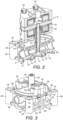
Figure 3 shows a perspective view of the valve housing of the servovalve ofFigures 1 and2 ; -
Figure 4 shows a bottom view of the valve housing ofFigure 3 ; -
Figure 5 shows a vertical cross section through the valve housing ofFigure 3 ; -
Figure 6 shows a perspective view of a further embodiment of valve housing in accordance with the disclosure; -
Figure 7 shows a bottom view of the valve housing ofFigure 6 ; -
Figure 8 shows a detail of a further embodiment of valve housing in accordance with the disclosure; and -
Figure 9 shows a detail of the attachment of the valve housing ofFigure 8 to a torque motor. - With reference to
Figures 1 to 5 , a single stage flapper type servovalve 2 is illustrated. - The servovalve 2 comprises a valve housing 4 to which is mounted a
flapper actuator 6, in particular atorque motor 6. - As can be seen from
Figures 2 and5 , the valve housing 4 comprises abore 8 in which are fitted, in particular press fitted a pair ofopposed nozzles 10. Aflapper element 12 which is coupled to thetorque motor 6 is arranged between the pair ofnozzles 10. The valve housing 4 further comprises a plurality offluid ports nozzles 10. Theports housing bore 8. Thecentral port 14 is typically called a control port and its function is to communicate working fluid to an actuator (not shown). - The
bore 8 is closed at its opposed ends byplugs 20 which may be press fitted into the ends of thebore 8. - This general type of servovalve is well known in the art, being used in a wide variety of aircraft control systems, for example in fuel and air management systems for operating engine fuel metering valves, active clearance control valves, bleed valves and so on.
- However, the servovalve 2 of the disclosure departs from known servovalves in a number of significant respects which will be described further below.
- As mentioned earlier, in prior art single stage flapper type servovalves, the valve housing 4 is typically made from aluminium. This is because the servovalve will typically be used in aircraft systems, where weight is of concern, and for ease of manufacture. However, the
nozzles 10 are formed of stainless steel and must be positioned very accurately in the in valve housing. - The use of aluminium as a valve housing material, while being advantageous in many respects has been recognised as being not ideal in others. For example, Aluminium may lose its physical properties at elevated temperatures. Aluminium alloy 6061 T651 which is a material typically used for servovalve housings may lose up to 50% of its Ultimate Tensile Stress and may suffer fatigue after as little as 0.5 hours exposure to temperatures of 260°C. Moreover, the
nozzles 10 have to be very accurately positioned in thebore 8 to ensure proper operation of the servovalve 2 without any degradation in performance over time. As thenozzles 10 are generally press fitted within thebore 8, due to the difference in the coefficient of thermal expansion of the nozzle and housing materials, the interference fit may relax too much at higher temperatures resulting in movement of thenozzles 10. - To overcome or at least mitigate these potential drawbacks, in accordance with the disclosure, the servovalve housing 4 and the
nozzles 10 are both made from a stainless steel material. Thus embodiments of the disclosure have the advantage that the servovalve 2 may be used in higher temperature environments without weakening the valve housing 4. Moreover, as the coefficients of thermal expansion of the valve housing 4 and thenozzles 10 will be much closer to one another, an improved interference fit will be formed between the valve body 4 and thenozzles 10 which will not significantly loosen during use, even at elevated temperatures. - In embodiments of the disclosure the valve housing 4 and the
nozzles 10 are made from stainless steels having the same or similar coefficients of thermal expansion. By similar in this context may be meant within +/- 10%, or, more narrowly within +/-5%. This will have the advantage of eliminating or substantially reducing any loss in press fit at high temperatures and will allow looser tolerances in the internal diameter of thebore 8 and the external diameter of thenozzles 10, where previously very tight tolerances had to be met due to the very different coefficients of thermal expansion of the bore and nozzle materials. In some embodiments, the valve housing 4 and thenozzles 10 may be made from the same stainless steel material, for example from A 286. - In embodiments of the invention, the
plugs 20 sealing thebore 8 may also be made from a stainless steel material, for example one having a coefficient of thermal expansion similar to (as discussed above) or equal to that of the valve housing 4. Theplugs 20 may be therefore be made from made from the same stainless steel material as the valve housing 4, for example from A286. - The valve housing 4 comprises a mounting 22 for the
torque motor 6. As can be seen fromFigure 3 , in this embodiment, the mounting 22 comprises a mountingboss 24 upstanding from atop plate 26 of the valve housing 4. Achimney 28 is formed integrally with and extends upwardly from the valve housing 4. As can be seen fromFigure 2 , theflapper element 12 of the servovalve extends through thechimney 28. Thechimney 28 is formed with arecess 30 at its upper end for receiving a seal, for example an O-ring seal 32 which seals against the upper end of theflapper 12 to seal thetorque motor 6 from the fluid in the valve housing 4. - The
torque motor 6 is attached to the valve housing 4 by means offasteners 34 which extend into receiving bores 36 formed in the upper surface of the mountingboss 24. - The servovalve 2 is mounted to a support surface 40 (
Figure 1 ) by means offasteners 42, for example screw fasteners which are received in mountingbores 44 formed at the periphery of the valve housing 4. In this embodiment, the mounting bores 44 are formed intubular elements 46. Thetubular elements 46 are attached at their upper end to thetop plate 26 of the valve housing 2 bywebs 60. Thetubular elements 46 are attached to acentral portion 48 of the valve housing 2 in which is formed the valve bore 8 and theports elements 50, in this embodiment a plurality of connectingarms 50. This creates a lattice-like structure for the valve body 4, withvoids 52 being formed within the structure between the peripheral connectingtubes 46 and thecentral portion 48 of the valve housing 2. This acts significantly reduce the weight of the valve housing 2, which is of particular importance when using stainless steel as the housing material. Thecentral portion 48 itself has a generally tubular construction, with the valve bore 8 being formed by atubular wall structure 49 and theports tubular elements wall 49. - In the embodiment of
Figures 1 to 5 , the connectingarms 50 are arranged in a rectangular lattice arrangement joining the connecting tubes to each other and to alower portion 54 of thecentral portion 48 of the valve housing 4, surrounding thevalve ports arms 56 extend upwardly on either side of the valve housing 4 from thenodes 58 formed between the connectingarms 50 which extend generally parallel to the axis A of thebore 8 to connect to thetop plate 26 of the valve housing 4. This provides a stiff, yet light valve housing construction. - It will be appreciated that other forms of lattice structure may be employed. A further embodiment in accordance with the disclosure, which incorporates such a structure, is illustrated in
Figures 6 and 7 . The structure of the valve housing 104 is generally the same as that of the valve housing 4 of the first described embodiment, apart from the lattice structure. Only the lattice structure will therefore be described in detail below. - In this embodiment, the peripheral
tubular elements 146 arranged on either side of the central portion 148 of thevalve housing 8 are connected together by first connectingarms 150a which extend generally parallel to the axis of thebore 108 of the valve housing 104. Those connectingtubular elements 146 are then connected to an end mid-height portion 154a of the central portion 148 of the valve housing, generally in line with the axis A of the valve housing bore 108, by second, shorter connectingarms 150b. Thetubular elements 146 are further connected to a central mid-height portion 154b by diagonally extendingarms 150c. Relatively short vertical connectingarms 156 connect the first connectingarms 150a to thetop plate 126 of the valve housing 104. The top ends of the connectingelements 146 are also attached to thetop plate 126 by webs 160. - This structure therefore also defines
large voids 152 in the valve housing 104, thereby significantly reducing its weight. - The valve housing 4, 104 of the above described embodiments may be made by any suitable manufacturing technique. However, a particularly advantageous method of manufacturing for use in the present disclosure is additive manufacturing. Additive manufacturing is a technique in which successive layers of material are deposited one upon the other to create a desired shape. An example of such a process which may be usefully employed in producing servovalve housings in accordance with the disclosure is laser powder bed fusion. Additive manufacturing has the advantage that it allows relatively complicated shapes to be produced. Stainless steel is a material which is capable of use in such a process.
- The additively manufactured housing 4, 104 may be produced to a near-net shape and then finish machined to provide various features such as the
bore 8. - The use of stainless steel as a valve housing material may also allow modification and simplification of other aspects of the servovalve.
- As described briefly above, in a traditional servovalve construction, a
chimney 28 is integrally formed with the servovalve housing 4 and thechimney 28 is sealed to theflapper element 12 by a seal to avoid leakage of fluids from the servovalve housing 4 into thetorque motor 6. In the embodiment ofFigure 8 and 9 , however, thevalve housing 204 is provided with a muchshorter chimney 206 and aseparate tube 208 is attached to the top of thechimney 206. Thetube 208 may be relatively thin, for example between 0.05 mm and 0.15 mm thick. The wall thickness will be determined to a large extent by the operating pressure of the servovalve, so for an air servovalve the thickness may be about 0.05 mm, but for a fuel application where pressures would be higher, the thickness may be greater, for example about 0.08 mm to about 0.1 mm. The thickness may also be dependent to some extent on the total armature stiffness of the torque motor. The precise thickness can be determined as necessary for any particular application. Thetube 208 may, for example be received in agroove 210 in the top of thechimney 206. Thetube 208 is secured to thechimney 206 by a braze orweld 212. - The upper end of the
tube 208 is similarly attached to thetorque motor 6. In this embodiment thetube 208 is attached to atorque bridge 214 of thetorque motor 6, to which theflapper element 12 is attached. Thetube 208 may be received in agroove 216 in the bottom surface of thetorque bridge 214 and secured by a braze orweld 218. While fluid from theservovalve housing 204 will be able to enter the lower end of thetube 208, it will not be able to exit the upper end of thetube 208 due to the close fit between theflapper element 12 and the torque bridge and the braze orweld 218. - It will be seen from the above that various embodiments of the disclosure have distinct advantages over prior art servovalves. By using stainless steel as the material of the servovalve housing 4, the servovalve may potentially be used at higher operating temperatures, thereby potentially expanding the range of applications for such valves. The improved strength of the housing 4 due to its manufacture from stainless steel also means that the servovalve may be used not only at higher temperatures, but also at higher pressures.
- By making the
nozzles 10 and valve housing 4 of stainless steel, optionally the same material, the problem of potential loss of press fit at elevated temperatures is prevented. It also means that it may be possible to increase the tolerance on the bore and nozzle diameters, thereby facilitating manufacture and assembly of the servovalve 2. This also applies to theplugs 10 closing thebore 8 of the housing 4. - By designing the valve housing 4 with a lattice type construction, a significant reduction of weight may be achieved. In fact, it may be possible to produce housings which are lighter that hitherto known aluminium based housings, for example by as much as 30% lighter.
- The use of an additive manufacturing process will also be advantageous as it will all allow intricate shapes of housing to be produced. Moreover, in embodiments, the valve housing 4 may comprise internal voids which may further reduce the weight of the housing. For example, the individual tubular structures and connecting arms of the valve housing 4 may comprise voids. Such structures may be created using additive manufacturing, but not by conventional techniques such as casting or machining.
- It will be appreciated that the above description is of exemplary embodiments only and that modifications may be made thereto without departing from the scope of the disclosure.
Claims (15)
- A single stage flapper type servovalve (2; 102) comprising:a valve housing (4; 104; 204) comprising a bore (8; 108);a pair of opposed nozzles (10) arranged in the bore (8; 108); anda flapper element (12) arranged between the pair of nozzles (10);the valve housing (4; 104; 204) further comprising a plurality of fluid ports (14, 16, 18) for communicating a working fluid to and from the nozzles (10) and in fluid communication with the housing bore (8; 108);wherein the valve housing (4; 104; 204) and the nozzles (10) are both made from a stainless steel material.
- A single stage flapper type servovalve as claimed in claim 1, wherein the valve housing (4; 104; 204) and the nozzles (10) are made from stainless steels having the same or a similar coefficient of thermal expansion.
- A single stage flapper type servovalve as claimed in claim 2, wherein the valve housing (4; 104; 204) and the nozzles (10) are made from the same stainless steel.
- A single stage flapper type servovalve as claimed in any preceding claim, further comprising a torque motor (6) mounted to the valve housing (4; 104; 204).
- A single stage flapper type servovalve as claimed in claim 4, further comprising a stainless steel connecting tube (208) brazed or welded between the valve housing (204) and the torque motor (6), the flapper element (12) extending through the connecting tube (208).
- A single stage flapper type servovalve as claimed in any preceding claim, further comprising respective plugs (20) closing the ends of the valve housing bore (8; 108) , the plugs (20) also being formed of a stainless steel.
- A single stage flapper type servovalve housing (4; 104; 204) comprising:a bore (8; 108) for receiving a pair of opposed nozzles (10) therein; anda plurality of fluid ports (14, 16, 18) in fluid communication with the housing bore (8; 108);wherein the valve housing (4; 104; 204) is made from stainless steel.
- A single stage flapper type servovalve or a single stage flapper type servovalve housing as claimed in any preceding claim, wherein the valve housing (4; 104; 204) further comprises a plurality of mounting bores (44), optionally at its periphery, for receiving fasteners (42) for mounting the valve housing to a surface (40).
- A single stage flapper type servovalve or single stage flapper type servovalve housing as claimed in claim 7, wherein the mounting bores (44) are formed as tubular elements (46; 146) attached to a further portion (48; 148) of the valve housing, for example a portion (48; 148) of the valve housing (4; 104; 204) in which is formed the valve bore (8; 108) and/or the ports (14, 16, 18), by means of one or more connecting elements (50; 150a; 150b; 150c).
- A single stage flapper type servovalve or single stage flapper type servovalve housing as claimed in claim 9, wherein the connecting elements comprise a plurality of connecting arms (50; 150a; 150b; 150c).
- A single stage flapper type servovalve or single stage flapper type servovalve housing as claimed in claim 10, wherein the connecting arms form a lattice structure with voids (52; 152) formed between the connecting arms (50; 150a; 150b; 150c) and the further portion (48; 148) of the valve housing (4; 104; 204), for example the portion (48; 148) of the valve housing (4; 104; 204) in which is formed the valve bore (8; 108) and/or the ports (14, 16, 18).
- A single stage flapper type servovalve or single stage flapper type servovalve housing as claimed in any preceding claim, wherein the valve housing (4; 104; 204) is formed by an additive manufacturing technique.
- A method of manufacturing a single stage flapper type servovalve housing (4; 104; 204) comprising: a bore (8; 108) for receiving a pair of opposed nozzles (10) therein and a plurality of fluid ports (14, 16, 18) in fluid communication with the housing bore (8; 108) comprising additively manufacturing the valve housing (4; 104; 204) from a stainless steel material.
- A method of manufacturing a single stage flapper type servovalve housing as claimed in claim 13, further comprising brazing or welding one end of a stainless steel connecting tube (208) to the valve housing for attachment to a torque motor (6).
- A method of assembling a single stage flapper type servovalve as claimed in claim 5 comprising:manufacturing the servovalve housing (4; 104; 204) by the method of claim 14; andbrazing or welding the other end of the connecting tube (208) to the torque motor (6), for example a torque bridge (214) of the torque motor (6).
Priority Applications (1)
| Application Number | Priority Date | Filing Date | Title |
|---|---|---|---|
| EP23186233.5A EP4245541B1 (en) | 2018-09-26 | 2018-09-26 | Servovalves |
Applications Claiming Priority (2)
| Application Number | Priority Date | Filing Date | Title |
|---|---|---|---|
| EP23186233.5A EP4245541B1 (en) | 2018-09-26 | 2018-09-26 | Servovalves |
| EP18461614.2A EP3628874B1 (en) | 2018-09-26 | 2018-09-26 | Servovalves |
Related Parent Applications (1)
| Application Number | Title | Priority Date | Filing Date |
|---|---|---|---|
| EP18461614.2A Division EP3628874B1 (en) | 2018-09-26 | 2018-09-26 | Servovalves |
Publications (3)
| Publication Number | Publication Date |
|---|---|
| EP4245541A2 true EP4245541A2 (en) | 2023-09-20 |
| EP4245541A3 EP4245541A3 (en) | 2023-11-22 |
| EP4245541B1 EP4245541B1 (en) | 2025-08-06 |
Family
ID=63713805
Family Applications (2)
| Application Number | Title | Priority Date | Filing Date |
|---|---|---|---|
| EP23186233.5A Active EP4245541B1 (en) | 2018-09-26 | 2018-09-26 | Servovalves |
| EP18461614.2A Active EP3628874B1 (en) | 2018-09-26 | 2018-09-26 | Servovalves |
Family Applications After (1)
| Application Number | Title | Priority Date | Filing Date |
|---|---|---|---|
| EP18461614.2A Active EP3628874B1 (en) | 2018-09-26 | 2018-09-26 | Servovalves |
Country Status (2)
| Country | Link |
|---|---|
| US (1) | US11306747B2 (en) |
| EP (2) | EP4245541B1 (en) |
Families Citing this family (1)
| Publication number | Priority date | Publication date | Assignee | Title |
|---|---|---|---|---|
| CN119222376B (en) * | 2024-10-23 | 2026-05-01 | 河南航天液压气动技术有限公司 | High-temperature gas flow automatic regulating valve |
Citations (1)
| Publication number | Priority date | Publication date | Assignee | Title |
|---|---|---|---|---|
| EP3473902A1 (en) * | 2017-10-23 | 2019-04-24 | Hamilton Sundstrand Corporation | Servo valve housing |
Family Cites Families (15)
| Publication number | Priority date | Publication date | Assignee | Title |
|---|---|---|---|---|
| US2824574A (en) * | 1955-04-19 | 1958-02-25 | Westinghouse Electric Corp | Hydraulic servo-valve |
| US2961002A (en) * | 1958-09-29 | 1960-11-22 | Carroll G Gordon | Electro-hydraulic servo valve |
| US3015343A (en) * | 1958-11-24 | 1962-01-02 | Vickers Inc | Power transmission |
| US3318320A (en) * | 1964-02-07 | 1967-05-09 | Westinghouse Electric Corp | Retractable nozzle flapper valve |
| US3323090A (en) * | 1964-06-04 | 1967-05-30 | Obrien D G Inc | Fluid seal for a torque motor |
| US3817150A (en) * | 1972-12-29 | 1974-06-18 | Sli Ind | Hydraulic actuator with mechanical feedback |
| US4538633A (en) * | 1983-02-18 | 1985-09-03 | Parker-Hannifin Corporation | Optical-hydraulic control system |
| US4617966A (en) * | 1983-12-01 | 1986-10-21 | Bardle Servovalve Co. | Electromagnetic positioner for a servovalve or the like |
| US4742322A (en) | 1986-06-27 | 1988-05-03 | Cadillac Gage Textron Inc. | Direct drive servovalve with rotary force motor |
| US4800924A (en) | 1987-04-24 | 1989-01-31 | Davidson Textron Inc. | Direct drive servovalve with rotary valve |
| US5070898A (en) * | 1991-02-11 | 1991-12-10 | Hsc Controls Inc. | Metering valve |
| US5282570A (en) | 1992-05-12 | 1994-02-01 | General Electric Company | Electronically controlled accumulator injector |
| US5524525A (en) | 1994-05-23 | 1996-06-11 | A.I.L. Inc. | Rotary servo valve and guidance system apparatus for controlling the same |
| CN104930243B (en) * | 2014-03-18 | 2019-09-10 | 费希尔控制国际公司 | Integrated Converter |
| US10738800B2 (en) * | 2015-10-02 | 2020-08-11 | Asco, L.P. | Combination manifold block, valve housing and spool valve assembly for a manifold bank |
-
2018
- 2018-09-26 EP EP23186233.5A patent/EP4245541B1/en active Active
- 2018-09-26 EP EP18461614.2A patent/EP3628874B1/en active Active
-
2019
- 2019-08-07 US US16/533,836 patent/US11306747B2/en active Active
Patent Citations (1)
| Publication number | Priority date | Publication date | Assignee | Title |
|---|---|---|---|---|
| EP3473902A1 (en) * | 2017-10-23 | 2019-04-24 | Hamilton Sundstrand Corporation | Servo valve housing |
Also Published As
| Publication number | Publication date |
|---|---|
| US11306747B2 (en) | 2022-04-19 |
| EP3628874B1 (en) | 2023-07-19 |
| EP4245541B1 (en) | 2025-08-06 |
| EP3628874A1 (en) | 2020-04-01 |
| US20200096016A1 (en) | 2020-03-26 |
| EP4245541A3 (en) | 2023-11-22 |
Similar Documents
| Publication | Publication Date | Title |
|---|---|---|
| EP2188518B1 (en) | Ignition device for a laser ignition of an internal combustion engine | |
| EP3831582B1 (en) | A combination manifold and valve housing for a manifold bank made by an additive manufacturing method | |
| EP3039299B1 (en) | Electro-hydraulic actuator | |
| CN108350911B (en) | Assembly of a manifold module, a valve housing and a slide valve assembly for a manifold group | |
| US10823306B2 (en) | Pneumatic valve | |
| US10072773B2 (en) | Valve assembly and method of cooling | |
| US11306747B2 (en) | Servovalves | |
| US20170138489A1 (en) | Hard coated supply biased spool valves | |
| US20200080662A1 (en) | Valve assembly and method of cooling | |
| US20220299122A1 (en) | Additive manufacturing and generative design hydraulic shuttle valve | |
| CN108457922A (en) | Hard conating supplies offset spool valve | |
| US11898652B2 (en) | Flow control device and trim cartridge assembly for a flow control device | |
| US9447797B2 (en) | Servovalve actuation | |
| EP3418587B1 (en) | Hydraulic valve | |
| EP3460259B1 (en) | Method for manufacturing a torsion spring for use in a servovalve and the torsion spring itself | |
| EP4019787B1 (en) | Servo valve assembly | |
| EP4141263B1 (en) | Servovalve comprising a filter assembly | |
| US11384855B2 (en) | Fluid pressure valve | |
| JP2005098376A (en) | Valve with joined housing | |
| JPH10184967A (en) | Valve housing and method of manufacturing the same | |
| Mailhan et al. | Innovative Flow Servovalve with Redundant Stack Actuator for Pitch Actuation Application | |
| JPH0626993A (en) | Cylindrical body with cooling passage |
Legal Events
| Date | Code | Title | Description |
|---|---|---|---|
| PUAI | Public reference made under article 153(3) epc to a published international application that has entered the european phase |
Free format text: ORIGINAL CODE: 0009012 |
|
| STAA | Information on the status of an ep patent application or granted ep patent |
Free format text: STATUS: THE APPLICATION HAS BEEN PUBLISHED |
|
| AC | Divisional application: reference to earlier application |
Ref document number: 3628874 Country of ref document: EP Kind code of ref document: P |
|
| AK | Designated contracting states |
Kind code of ref document: A2 Designated state(s): AL AT BE BG CH CY CZ DE DK EE ES FI FR GB GR HR HU IE IS IT LI LT LU LV MC MK MT NL NO PL PT RO RS SE SI SK SM TR |
|
| REG | Reference to a national code |
Ref country code: DE Ref legal event code: R079 Free format text: PREVIOUS MAIN CLASS: B33Y0080000000 Ipc: F15B0013043000 Ref country code: DE Ref legal event code: R079 Ref document number: 602018084479 Country of ref document: DE Free format text: PREVIOUS MAIN CLASS: B33Y0080000000 Ipc: F15B0013043000 |
|
| PUAL | Search report despatched |
Free format text: ORIGINAL CODE: 0009013 |
|
| AK | Designated contracting states |
Kind code of ref document: A3 Designated state(s): AL AT BE BG CH CY CZ DE DK EE ES FI FR GB GR HR HU IE IS IT LI LT LU LV MC MK MT NL NO PL PT RO RS SE SI SK SM TR |
|
| RIC1 | Information provided on ipc code assigned before grant |
Ipc: F15B 13/043 20060101AFI20231013BHEP |
|
| STAA | Information on the status of an ep patent application or granted ep patent |
Free format text: STATUS: REQUEST FOR EXAMINATION WAS MADE |
|
| 17P | Request for examination filed |
Effective date: 20240522 |
|
| RBV | Designated contracting states (corrected) |
Designated state(s): AL AT BE BG CH CY CZ DE DK EE ES FI FR GB GR HR HU IE IS IT LI LT LU LV MC MK MT NL NO PL PT RO RS SE SI SK SM TR |
|
| GRAP | Despatch of communication of intention to grant a patent |
Free format text: ORIGINAL CODE: EPIDOSNIGR1 |
|
| STAA | Information on the status of an ep patent application or granted ep patent |
Free format text: STATUS: GRANT OF PATENT IS INTENDED |
|
| RIC1 | Information provided on ipc code assigned before grant |
Ipc: F15C 3/14 20060101ALN20250217BHEP Ipc: B33Y 80/00 20150101ALI20250217BHEP Ipc: B22F 10/28 20210101ALI20250217BHEP Ipc: F15B 13/043 20060101AFI20250217BHEP |
|
| INTG | Intention to grant announced |
Effective date: 20250226 |
|
| GRAS | Grant fee paid |
Free format text: ORIGINAL CODE: EPIDOSNIGR3 |
|
| GRAA | (expected) grant |
Free format text: ORIGINAL CODE: 0009210 |
|
| STAA | Information on the status of an ep patent application or granted ep patent |
Free format text: STATUS: THE PATENT HAS BEEN GRANTED |
|
| AC | Divisional application: reference to earlier application |
Ref document number: 3628874 Country of ref document: EP Kind code of ref document: P |
|
| AK | Designated contracting states |
Kind code of ref document: B1 Designated state(s): AL AT BE BG CH CY CZ DE DK EE ES FI FR GB GR HR HU IE IS IT LI LT LU LV MC MK MT NL NO PL PT RO RS SE SI SK SM TR |
|
| RAP3 | Party data changed (applicant data changed or rights of an application transferred) |
Owner name: HAMILTON SUNDSTRAND CORPORATION |
|
| REG | Reference to a national code |
Ref country code: GB Ref legal event code: FG4D |
|
| REG | Reference to a national code |
Ref country code: CH Ref legal event code: EP |
|
| REG | Reference to a national code |
Ref country code: IE Ref legal event code: FG4D |
|
| REG | Reference to a national code |
Ref country code: DE Ref legal event code: R096 Ref document number: 602018084479 Country of ref document: DE |
|
| PGFP | Annual fee paid to national office [announced via postgrant information from national office to epo] |
Ref country code: DE Payment date: 20250820 Year of fee payment: 8 |
|
| PGFP | Annual fee paid to national office [announced via postgrant information from national office to epo] |
Ref country code: GB Payment date: 20250923 Year of fee payment: 8 |
|
| REG | Reference to a national code |
Ref country code: NL Ref legal event code: MP Effective date: 20250806 |
|
| PG25 | Lapsed in a contracting state [announced via postgrant information from national office to epo] |
Ref country code: IS Free format text: LAPSE BECAUSE OF FAILURE TO SUBMIT A TRANSLATION OF THE DESCRIPTION OR TO PAY THE FEE WITHIN THE PRESCRIBED TIME-LIMIT Effective date: 20251206 |
|
| PG25 | Lapsed in a contracting state [announced via postgrant information from national office to epo] |
Ref country code: NO Free format text: LAPSE BECAUSE OF FAILURE TO SUBMIT A TRANSLATION OF THE DESCRIPTION OR TO PAY THE FEE WITHIN THE PRESCRIBED TIME-LIMIT Effective date: 20251106 |
|
| REG | Reference to a national code |
Ref country code: LT Ref legal event code: MG9D |
|
| PG25 | Lapsed in a contracting state [announced via postgrant information from national office to epo] |
Ref country code: PT Free format text: LAPSE BECAUSE OF FAILURE TO SUBMIT A TRANSLATION OF THE DESCRIPTION OR TO PAY THE FEE WITHIN THE PRESCRIBED TIME-LIMIT Effective date: 20251209 |
|
| PG25 | Lapsed in a contracting state [announced via postgrant information from national office to epo] |
Ref country code: FI Free format text: LAPSE BECAUSE OF FAILURE TO SUBMIT A TRANSLATION OF THE DESCRIPTION OR TO PAY THE FEE WITHIN THE PRESCRIBED TIME-LIMIT Effective date: 20250806 |
|
| PG25 | Lapsed in a contracting state [announced via postgrant information from national office to epo] |
Ref country code: HR Free format text: LAPSE BECAUSE OF FAILURE TO SUBMIT A TRANSLATION OF THE DESCRIPTION OR TO PAY THE FEE WITHIN THE PRESCRIBED TIME-LIMIT Effective date: 20250806 Ref country code: NL Free format text: LAPSE BECAUSE OF FAILURE TO SUBMIT A TRANSLATION OF THE DESCRIPTION OR TO PAY THE FEE WITHIN THE PRESCRIBED TIME-LIMIT Effective date: 20250806 |
|
| PG25 | Lapsed in a contracting state [announced via postgrant information from national office to epo] |
Ref country code: GR Free format text: LAPSE BECAUSE OF FAILURE TO SUBMIT A TRANSLATION OF THE DESCRIPTION OR TO PAY THE FEE WITHIN THE PRESCRIBED TIME-LIMIT Effective date: 20251107 |
|
| PG25 | Lapsed in a contracting state [announced via postgrant information from national office to epo] |
Ref country code: SE Free format text: LAPSE BECAUSE OF FAILURE TO SUBMIT A TRANSLATION OF THE DESCRIPTION OR TO PAY THE FEE WITHIN THE PRESCRIBED TIME-LIMIT Effective date: 20250806 |
|
| PG25 | Lapsed in a contracting state [announced via postgrant information from national office to epo] |
Ref country code: LV Free format text: LAPSE BECAUSE OF FAILURE TO SUBMIT A TRANSLATION OF THE DESCRIPTION OR TO PAY THE FEE WITHIN THE PRESCRIBED TIME-LIMIT Effective date: 20250806 |
|
| PG25 | Lapsed in a contracting state [announced via postgrant information from national office to epo] |
Ref country code: BG Free format text: LAPSE BECAUSE OF FAILURE TO SUBMIT A TRANSLATION OF THE DESCRIPTION OR TO PAY THE FEE WITHIN THE PRESCRIBED TIME-LIMIT Effective date: 20250806 Ref country code: PL Free format text: LAPSE BECAUSE OF FAILURE TO SUBMIT A TRANSLATION OF THE DESCRIPTION OR TO PAY THE FEE WITHIN THE PRESCRIBED TIME-LIMIT Effective date: 20250806 |
|
| PG25 | Lapsed in a contracting state [announced via postgrant information from national office to epo] |
Ref country code: RS Free format text: LAPSE BECAUSE OF FAILURE TO SUBMIT A TRANSLATION OF THE DESCRIPTION OR TO PAY THE FEE WITHIN THE PRESCRIBED TIME-LIMIT Effective date: 20251106 |
|
| PG25 | Lapsed in a contracting state [announced via postgrant information from national office to epo] |
Ref country code: ES Free format text: LAPSE BECAUSE OF FAILURE TO SUBMIT A TRANSLATION OF THE DESCRIPTION OR TO PAY THE FEE WITHIN THE PRESCRIBED TIME-LIMIT Effective date: 20250806 |
|
| REG | Reference to a national code |
Ref country code: AT Ref legal event code: MK05 Ref document number: 1822119 Country of ref document: AT Kind code of ref document: T Effective date: 20250806 |
|
| PG25 | Lapsed in a contracting state [announced via postgrant information from national office to epo] |
Ref country code: RO Free format text: LAPSE BECAUSE OF FAILURE TO SUBMIT A TRANSLATION OF THE DESCRIPTION OR TO PAY THE FEE WITHIN THE PRESCRIBED TIME-LIMIT Effective date: 20250806 |
|
| PG25 | Lapsed in a contracting state [announced via postgrant information from national office to epo] |
Ref country code: SM Free format text: LAPSE BECAUSE OF FAILURE TO SUBMIT A TRANSLATION OF THE DESCRIPTION OR TO PAY THE FEE WITHIN THE PRESCRIBED TIME-LIMIT Effective date: 20250806 |
|
| PG25 | Lapsed in a contracting state [announced via postgrant information from national office to epo] |
Ref country code: DK Free format text: LAPSE BECAUSE OF FAILURE TO SUBMIT A TRANSLATION OF THE DESCRIPTION OR TO PAY THE FEE WITHIN THE PRESCRIBED TIME-LIMIT Effective date: 20250806 |
|
| PG25 | Lapsed in a contracting state [announced via postgrant information from national office to epo] |
Ref country code: AT Free format text: LAPSE BECAUSE OF FAILURE TO SUBMIT A TRANSLATION OF THE DESCRIPTION OR TO PAY THE FEE WITHIN THE PRESCRIBED TIME-LIMIT Effective date: 20250806 |
|
| PG25 | Lapsed in a contracting state [announced via postgrant information from national office to epo] |
Ref country code: IT Free format text: LAPSE BECAUSE OF FAILURE TO SUBMIT A TRANSLATION OF THE DESCRIPTION OR TO PAY THE FEE WITHIN THE PRESCRIBED TIME-LIMIT Effective date: 20250806 |
|
| PG25 | Lapsed in a contracting state [announced via postgrant information from national office to epo] |
Ref country code: CZ Free format text: LAPSE BECAUSE OF FAILURE TO SUBMIT A TRANSLATION OF THE DESCRIPTION OR TO PAY THE FEE WITHIN THE PRESCRIBED TIME-LIMIT Effective date: 20250806 |
|
| PG25 | Lapsed in a contracting state [announced via postgrant information from national office to epo] |
Ref country code: EE Free format text: LAPSE BECAUSE OF FAILURE TO SUBMIT A TRANSLATION OF THE DESCRIPTION OR TO PAY THE FEE WITHIN THE PRESCRIBED TIME-LIMIT Effective date: 20250806 Ref country code: SK Free format text: LAPSE BECAUSE OF FAILURE TO SUBMIT A TRANSLATION OF THE DESCRIPTION OR TO PAY THE FEE WITHIN THE PRESCRIBED TIME-LIMIT Effective date: 20250806 |
|
| REG | Reference to a national code |
Ref country code: CH Ref legal event code: H13 Free format text: ST27 STATUS EVENT CODE: U-0-0-H10-H13 (AS PROVIDED BY THE NATIONAL OFFICE) Effective date: 20260504 |