EP4245505A1 - Link mechanism, link device and drawing machine - Google Patents
Link mechanism, link device and drawing machine Download PDFInfo
- Publication number
- EP4245505A1 EP4245505A1 EP21891400.0A EP21891400A EP4245505A1 EP 4245505 A1 EP4245505 A1 EP 4245505A1 EP 21891400 A EP21891400 A EP 21891400A EP 4245505 A1 EP4245505 A1 EP 4245505A1
- Authority
- EP
- European Patent Office
- Prior art keywords
- bearing
- cover member
- link
- guide roller
- rail
- Prior art date
- Legal status (The legal status is an assumption and is not a legal conclusion. Google has not performed a legal analysis and makes no representation as to the accuracy of the status listed.)
- Granted
Links
Images



Classifications
-
- B—PERFORMING OPERATIONS; TRANSPORTING
- B29—WORKING OF PLASTICS; WORKING OF SUBSTANCES IN A PLASTIC STATE IN GENERAL
- B29C—SHAPING OR JOINING OF PLASTICS; SHAPING OF MATERIAL IN A PLASTIC STATE, NOT OTHERWISE PROVIDED FOR; AFTER-TREATMENT OF THE SHAPED PRODUCTS, e.g. REPAIRING
- B29C55/00—Shaping by stretching, e.g. drawing through a die; Apparatus therefor
- B29C55/02—Shaping by stretching, e.g. drawing through a die; Apparatus therefor of plates or sheets
- B29C55/10—Shaping by stretching, e.g. drawing through a die; Apparatus therefor of plates or sheets multiaxial
- B29C55/12—Shaping by stretching, e.g. drawing through a die; Apparatus therefor of plates or sheets multiaxial biaxial
- B29C55/16—Shaping by stretching, e.g. drawing through a die; Apparatus therefor of plates or sheets multiaxial biaxial simultaneously
-
- B—PERFORMING OPERATIONS; TRANSPORTING
- B29—WORKING OF PLASTICS; WORKING OF SUBSTANCES IN A PLASTIC STATE IN GENERAL
- B29C—SHAPING OR JOINING OF PLASTICS; SHAPING OF MATERIAL IN A PLASTIC STATE, NOT OTHERWISE PROVIDED FOR; AFTER-TREATMENT OF THE SHAPED PRODUCTS, e.g. REPAIRING
- B29C55/00—Shaping by stretching, e.g. drawing through a die; Apparatus therefor
- B29C55/02—Shaping by stretching, e.g. drawing through a die; Apparatus therefor of plates or sheets
- B29C55/10—Shaping by stretching, e.g. drawing through a die; Apparatus therefor of plates or sheets multiaxial
- B29C55/12—Shaping by stretching, e.g. drawing through a die; Apparatus therefor of plates or sheets multiaxial biaxial
- B29C55/16—Shaping by stretching, e.g. drawing through a die; Apparatus therefor of plates or sheets multiaxial biaxial simultaneously
- B29C55/165—Apparatus therefor
-
- B—PERFORMING OPERATIONS; TRANSPORTING
- B29—WORKING OF PLASTICS; WORKING OF SUBSTANCES IN A PLASTIC STATE IN GENERAL
- B29C—SHAPING OR JOINING OF PLASTICS; SHAPING OF MATERIAL IN A PLASTIC STATE, NOT OTHERWISE PROVIDED FOR; AFTER-TREATMENT OF THE SHAPED PRODUCTS, e.g. REPAIRING
- B29C55/00—Shaping by stretching, e.g. drawing through a die; Apparatus therefor
- B29C55/02—Shaping by stretching, e.g. drawing through a die; Apparatus therefor of plates or sheets
- B29C55/20—Edge clamps
Definitions
- the present invention relates to a link mechanism, a link device, and a stretching machine.
- Patent Document 1 Japanese Patent No. 4379306 discloses a simultaneous biaxial stretching machine in which longitudinal stretching and transverse stretching of a sheet-like object are performed simultaneously.
- the simultaneous biaxial stretching machine disclosed in Patent Document 1 includes endless link devices, and the endless link device includes equal-length link units formed like a folding scale.
- the equal-length link unit disclosed in Patent Document 1 includes a plurality of rollers that are rotatably supported by bearings and move on the rails while rotating.
- Patent Document 1 Japanese Patent No. 4379306
- a link mechanism constitutes a link device used in a stretching machine configured to stretch a film.
- the link mechanism includes a guide roller whose both ends in an axial direction are open and which moves along a rail while rotating, a shaft penetrating the guide roller, a bearing interposed between the guide roller and the shaft and rotatably supporting the guide roller, and a cover member that covers the bearing is provided on at least one of one end side of the guide roller in the axial direction and the other end side of the guide roller in the axial direction.
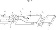
- FIG. 1 is a schematic diagram showing a configuration of a thin film manufacturing system including a stretching machine.
- a thin film manufacturing system 1 shown in FIG. 1 includes an extrusion apparatus (extruder, kneading extruder) 2, a T-die 3, a raw sheet cooling apparatus 4, a stretching machine 5, a take-off apparatus 6, and a winder apparatus 7.
- a thin film is manufactured through the following process.
- a raw material is supplied to a material supply unit (material supply port, hopper) 2a of the extrusion apparatus 2.
- the raw material to be supplied to the extrusion apparatus 2 contains a resin material (for example, thermoplastic resin material in pellet shape), additives, and others.
- the raw material supplied to the extrusion apparatus 2 is conveyed (transported) while being kneaded (mixed). Specifically, the raw material supplied to the extrusion apparatus 2 is melt and kneaded while being sent forward by the rotation of a screw in the extrusion apparatus 2.
- the raw material kneaded by the extrusion apparatus 2 (kneaded material) is supplied to the T-die 3.
- the kneaded material supplied to the T-die 3 is extruded toward the raw sheet cooling apparatus 4 through a slit of the T-die 3.
- the kneaded material supplied from the extrusion apparatus 2 to the T-die 3 is formed into a predetermined shape (in this case, film-like shape) by passing through the T-die 3.
- the kneaded material extruded from the T-die 3 is cooled and turned into a film 8 in the raw sheet cooling apparatus 4.
- the film 8 is a resin film in a solidified state (solid state). More specifically, the film 8 is a thermoplastic resin film.
- the film 8 is continuously extruded from the T-die 3. As a result, the film 8 is continuously supplied to the stretching machine 5.
- the film 8 supplied to the stretching machine 5 is stretched in an MD direction and a TD direction by the stretching machine 5.
- the film 8 subjected to the stretching process (stretching treatment) by the stretching machine 5 is conveyed to the winder apparatus 7 via the take-off apparatus 6 and is wound by the winder apparatus 7.
- the film 8 wound by the winder apparatus 7 is cut as appropriate.
- the thin film manufacturing system 1 shown in FIG. 1 manufactures a thin film through the process described above. Understandably, the thin film manufacturing system 1 can be variously modified in accordance with the properties of the thin film to be manufactured.
- an extraction tank may be provided near the take-off apparatus 6 shown in FIG. 1 , and the plasticizer (for example, paraffin or the like) contained in the film 8 may be removed in some cases.
- the stretching machine 5 constituting the thin film manufacturing system 1 stretches the film 8 in the MD direction and the TD direction while conveying the film 8 in the MD direction.
- the MD (Machine Direction) direction is a conveying direction of the film 8.
- the TD (Transverse Direction) direction is the direction that intersects the conveying direction of the film 8.
- the MD direction is referred to as a "conveying direction” or a "longitudinal direction”
- the TD direction is referred to as a "lateral direction” in some cases.
- the MD direction (conveying direction, longitudinal direction) and the TD direction (lateral direction) are the directions intersecting each other, and are more specifically the directions orthogonal to each other.
- the stretching machine 5 shown in FIG. 1 is a stretching machine capable of simultaneously stretching the film 8 in two directions intersecting each other while conveying the film 8, and is referred to as a "simultaneous biaxial stretching machine" in general.
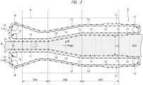
- FIG. 2 and FIG. 3 are plan views schematically showing the structure of the stretching machine 5.
- the stretching machine 5 includes a pair of link devices 10.
- the pair of link devices 10 are arranged apart from each other in plan view.
- one of the pair of link devices 10 is referred to as a "link device 10R” and the other of the pair of link devices 10 is referred to as a "link device 10L” for distinction in some cases. Understandably, such a distinction is merely for convenience of description.
- the link device 10R is arranged on the right side (R side) with respect to the conveying direction (MD direction), and the link device 10L is arranged on the left side (L side) with respect to the conveying direction (MD direction).
- the link device 10R and the link device 10L are separated from each other in the TD direction and face in the TD direction with the film 8 interposed therebetween.
- the film 8 is conveyed through the space between the link device 10R and the link device 10L in the MD direction.
- the space between the link device 10R and the link device 10L facing each other functions as a conveyance unit for conveying the film 8.
- the stretching machine 5 is divided into three regions 20A, 20B, and 20C in the conveying direction (MD direction).
- the region 20A serves as a preheating region
- the region 20B serves as a stretching region
- the region 20C serves as a heat fixing region.
- the regions 20A, 20B, and 20C are arranged in this order in the conveying direction (MD direction).
- the inlet of the film 8 in the stretching machine 5 exists in the region 20A.
- the outlet of the film 8 in the stretching machine 5 exists in the region 20C.
- the region 20B in which the stretching process is performed is present between the region 20A in which the inlet of the film 8 exists and the region 20C in which the outlet of the film 8 exists.
- a heat treatment unit 9 covers a part of the region 20A, all of the region 20B, and a part of the region 20C. Also, the heat treatment unit 9 covers the central parts of the link devices 10R and 10L, and heats the film 8 conveyed by the link devices 10R and 10L.
- the heat treatment unit 9 in this embodiment is composed of an oven capable of heating the film 8 to a desired temperature. The film 8 passes through the inside of the oven as the heat treatment unit 9 while being gripped by the link devices 10R and 10L.
- each of the link devices 10R and 10L includes a plurality of link mechanisms 11 coupled so as to form an endless chain, and each of the link mechanisms 11 has a clip 21 which is a jig for gripping the film 8.
- the film 8 is held by the clips 21 in the link mechanisms 11 constituting the link device 10R and the clips 21 in the link mechanisms 11 constituting the link device 10L. Namely, one side (R side/right side) of the film 8 is gripped by the plurality of clips 21 of the link device 10R, and the other side (L side/left side) of the film 8 is gripped by the plurality of clips 21 of the link device 10L.
- Each of the link devices 10R and 10L further includes a pair of rails 13 and 14 arranged on a support table (bed) in addition to the plurality of link mechanisms 11.
- the rail 13 is arranged on an inner circumferential side
- the rail 14 is arranged on an outer circumferential side.
- the rail 13 is referred to as an "inner rail” and the rail 14 is referred to as an “outer rail” in some cases.
- the rail 13 is referred to also as a "reference rail” or an "SP rail” and the rail 14 is referred to also as an "MD rail” in some cases.
- the rails 13 and 14 provided in each of the link devices 10R and 10L are annularly arranged over the regions 20A, 20B, and 20C. More specifically, the rails 13 and 14 are turned back in the region 20A in which the inlet of the film 8 is present, are turned back in the region 20C in which the outlet of the film 8 is present, and are annularly arranged over the regions 20A, 20B, and 20C.
- Three sprockets 15, 16, and 17 are provided inside the rail 13 of the link device 10R. Similarly, three sprockets 15, 16, and 17 are provided inside the rail 13 of the link device 10L.
- the sprockets 15 and 16 of the respective link devices 10R and 10L are arranged in the region 20A, and the sprockets 17 of the respective link devices 10R and 10L are arranged in the region 20C.
- the sprockets 15 and 16 are arranged outside the heat treatment unit 9 that covers a part of the region 20A.
- the sprockets 17 are arranged outside the heat treatment unit 9 that covers a part of the region 20C. Namely, the sprockets 15, 16, and 17 of the respective link devices 10R and 10L are arranged outside the oven as the heat treatment unit 9.
- the plurality of link mechanisms 11 in the link devices 10R and 10L are arranged on the rails 13 and 14 in a state of being able to move along the rails 13 and 14.
- the sprockets 15, 16, and 17 of the link device 10R shown in FIG. 3 engage with the plurality of link mechanisms 11 of the link device 10R. Therefore, when the sprockets 15, 16, and 17 rotate, a driving force acts on the plurality of link mechanisms 11 of the link device 10R, and the link mechanisms 11 move (run) along the rails 13 and 14 of the link device 10R.
- the sprockets 15, 16, and 17 of the link device 10L shown in FIG. 3 engage with the plurality of link mechanisms 11 of the link device 10L.
- the rails 13 and 14 of the respective link devices 10R and 10L are guide rails for moving (running) the plurality of link mechanisms 11 in a predetermined direction.
- the side facing the film 8 is referred to as a "film side”
- the side opposite to the film side is referred to as a "return side” in some cases.
- the side on which the plurality of link mechanisms 11 move from the inlet (IN) to the outlet (OUT) while the clips 21 are gripping the film 8 is the film side
- the side which is located on the opposite side of the film side and on which the plurality of link mechanisms 11 move from the outlet (OUT) to the inlet (IN) while the clips 21 do not grip the film 8 is the return side.
- the pitch between the adjacent link mechanisms 11 (referred to as a "link pitch" in some cases) of the plurality of link mechanisms 11 changes in accordance with the interval (separation distance) between the rail 13 and the rail 14. In other words, the pitch between the adjacent link mechanisms 11 can be adjusted by adjusting the separation distance between the rail 13 and the rail 14.
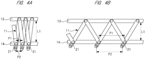
- FIG. 4A and FIG. 4B are plan views schematically showing the link mechanisms and the rails shown in FIG. 3 .
- the angle formed by the adjacent link mechanisms 11 becomes larger and the pitch P1 between the adjacent link mechanisms 11 becomes larger as the separation distance L1 between the rails 13 and 14 becomes smaller.
- the angle formed by the adjacent link mechanisms 11 becomes smaller and the pitch P1 between the adjacent link mechanisms 11 becomes smaller as the separation distance L1 between the rails 13 and 14 becomes larger.
- each link mechanism 11 has the clip 21 configured to grip the film 8. Therefore, the pitch P2 between the adjacent clips 21 also increases and decreases in accordance with the increase and decrease of the pitch P1 between the adjacent link mechanisms 11. Specifically, the pitch P1 between the link mechanisms 11 increases when the separation distance L1 of the rails 13 and 14 decreases, and the pitch P2 between the clips 21 also increases when the pitch P1 between the link mechanisms 11 increases ( FIG. 4A -> FIG. 4B ). On the other hand, the pitch P1 between the link mechanisms 11 decreases when the separation distance L1 of the rails 13 and 14 increases, and the pitch P2 between the clips 21 also decreases when the pitch P1 between the link mechanisms 11 decreases ( FIG. 4B -> FIG. 4A ).
- the film 8 supplied from the raw sheet cooling apparatus 4 to the stretching machine 5 is gripped by the link devices 10R and 10L at the inlet of the stretching machine 5.
- the film 8 is gripped by the clips 21 provided in the link mechanisms 11 of the link devices 10R and 10L shown in FIG. 2 and FIG. 3 .
- one side of the film 8 in the width direction is gripped by the clips 21 provided in the link mechanisms 11 of the link device 10R, and the other side of the film 8 in the width direction is gripped by the clips 21 provided in the link mechanisms 11 of the link device 10L.
- the film 8 whose both sides in the width direction are gripped by the clips 21 is conveyed from the inlet to the outlet of the stretching machine 5 along with the movement of the link mechanisms 11 including the clips 21, and passes through the region 20A (preheating region), the region 20B (stretching region), and the region 20C (heat fixing region) in this order.
- the film 8 is stretched in the MD direction and the TD direction while passing through the region 20B (stretching region). Thereafter, the film 8 reaches the outlet through the region 20C (heat fixing region) and is detached from the clips 21.
- the film 8 detached from the clips 21 is conveyed to the take-off apparatus 6 and is further conveyed from the take-off apparatus 6 to the winder apparatus 7.
- the interval (separation distance in the TD direction) L2 between the rails 13 and 14 of the link device 10R and the rails 13 and 14 of the link device 10L is almost constant. Therefore, the stretching process of the film 8 in the TD direction is not performed in the region 20A. Accordingly, the width (dimension in the TD direction) of the conveyed film 8 does not change and remains constant in the region 20A.
- the interval (separation distance) L1 between the rail 13 and the rail 14 of the link device 10R on the film side is almost constant. Therefore, in the region 20A, the pitch P1 of the link mechanisms 11 of the link device 10R on the film side is almost constant, and thus the pitch P2 of the clips 21 of the link device 10R on the film side is also almost constant. Further, in the region 20A, the interval (separation distance) L1 between the rail 13 and the rail 14 of the link device 10L on the film side is also almost constant.
- the pitch P1 of the link mechanisms 11 of the link device 10L on the film side is almost constant, and thus the pitch P2 of the clips 21 of the link device 10L on the film side is also almost constant.
- the stretching process of the film 8 in the MD direction is not performed in the region 20A. Namely, the stretching process of the film 8 in the TD direction and the MD direction is not performed in the region 20A.
- the operation of the stretching machine 5 in the region 20B will be described.
- the interval (interval in the TD direction) between the rails 13 and 14 of the link device 10R and the rails 13 and 14 of the link device 10L gradually increases along the conveying direction (MD direction). Therefore, in the region 20B, the film 8 is pulled and stretched in the TD direction as it advances in the conveying direction (MD direction). In other words, in the region 20B, the width (dimension in the TD direction) of the film 8 gradually increases as it advances in the conveying direction (MD direction).
- the interval (separation distance) L1 between the rail 13 and the rail 14 of the link device 10R on the film side gradually decreases along the conveying direction (MD direction), and the interval (separation distance) L1 between the rail 13 and the rail 14 of the link device 10L on the film side also gradually decreases along the conveying direction (MD direction). Therefore, in the region 20B, the pitch P1 of the link mechanisms 11 of the link device 10R on the film side gradually increases along the conveying direction (MD direction), and thus the pitch P2 of the clips 21 of the link device 10R on the film side also gradually increases.
- the pitch P1 of the link mechanisms 11 of the link device 10L on the film side gradually increases along the conveying direction (MD direction), and thus the pitch P2 of the clips 21 of the link device 10L on the film side also gradually increases.
- the film 8 is pulled and stretched in the MD direction as it advances in the conveying direction (MD direction).
- the film 8 is stretched in the TD direction and the MD direction as it advances in the conveying direction (MD direction). Namely, in the region 20B, the stretching process in the TD direction and the MD direction is applied to the film 8.
- the operation of the stretching machine 5 in the region 20C will be described.
- the interval (interval in the TD direction) between the rails 13 and 14 of the link device 10R and the rails 13 and 14 of the link device 10L is almost constant. Therefore, the stretching process of the film 8 in the TD direction is not performed in the region 20C. Accordingly, the width (dimension in the TD direction) of the conveyed film 8 does not change and remains constant in the region 20C.
- the interval (separation distance) L1 between the rail 13 and the rail 14 of the link device 10R on the film side is almost constant. Therefore, in the region 20C, the pitch P1 of the link mechanisms 11 of the link device 10R on the film side is almost constant, and thus the pitch P2 of the clips 21 of the link device 10R on the film side is also almost constant. Further, in the region 20C, the interval (separation distance) L1 between the rail 13 and the rail 14 of the link device 10L on the film side is almost constant.
- the pitch P1 of the link mechanisms 11 of the link device 10L on the film side is almost constant, and thus the pitch P2 of the clips 21 of the link device 10L on the film side is also almost constant.
- the stretching process of the film 8 in the MD direction is not performed in the region 20C. Namely, the stretching process of the film 8 in the TD direction and the MD direction is not performed in the region 20C.
- the pitch P1 of the link mechanisms 11 of the link device 10R on the film side is kept constant, and the pitch P1 of the link mechanisms 11 of the link device 10L on the film side is also kept constant.
- the pitch P1 of the link mechanisms 11 of the link device 10R on the film side and the pitch P1 of the link mechanisms 11 of the link device 10L on the film side are gradually expanded.
- the pitch P1 of the link mechanisms 11 of the link device 10R on the film side is kept constant again, and the pitch P1 of the link mechanisms 11 of the link device 10L on the film side is also kept constant again.
- the pitch P1 of the link mechanisms 11 in the region 20C is larger than the pitch P1 of the link mechanisms 11 in the region 20A.
- the pitch P2 of the clips 21 in the region 20C is larger than the pitch P2 of the clips 21 in the region 20A.
- the separation distance L1 between the rails 13 and 14 in the region 20C is smaller than the separation distance L1 between the rails 13 and 14 in the region 20A.
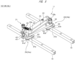
- FIG. 5 is a perspective view showing one of the plurality of link mechanisms shown in FIG. 3 in an enlarged manner.
- FIG. 6 is a cross-sectional view of the link mechanism shown in FIG. 5 .
- each of the link mechanisms 11 provided in the link devices 10R and 10L includes an upper link plate 22, a lower link plate 23, a pair of rail holders 24a and 24b, and a base member 25 bridging the pair of rail holders 24a and 24b in addition to the clip 21.
- One rail holder 24a is arranged on the rail 14, and the other rail holder 24b is arranged on the rail 13.
- the upper link plate 22 and the lower link plate 23 are plate-shaped members that extend linearly in plan view.
- the base member 25 is common with the upper link plate 22 and the lower link plate 23 in that it extends linearly in plan view, but the base member 25 is thicker than these.
- rail holders 24a and 24b are not particularly distinguished, they are collectively referred to as "rail holders 24".
- the rail holder 24a includes a roller holding portion 31a and a shaft 32a provided at the center of the roller holding portion 31a in the longitudinal direction.
- the roller holding portion 31a is arranged on the rail 14 so as to straddle the rail 14. Therefore, one end of the roller holding portion 31a arranged on the rail 14 in the longitudinal direction protrudes toward the inner side of the rail 14 (side facing the rail 13), and the other end of the roller holding portion 31a in the longitudinal direction protrudes toward the outer side of the rail 14 (opposite side of the side facing the rail 13). Also, when the roller holding portion 31a is arranged on the rail 14, the shaft 32a is located just above the rail 14.
- the shaft 32a of the rail holder 24a penetrates one ends of the upper link plate 22, the lower link plate 23, and the base member 25 in the longitudinal direction.
- a collar 33 is placed on the upper portion of the shaft 32a that penetrates one end side (base end side) of the base member 25 in the longitudinal direction and protrudes from the base member 25.
- Annular engaging portions 33a and 33b are integrally formed on both sides of the collar 33 in the axial direction.
- a lower insertion portion of the collar 33 located outside the engaging portion 33b in the axial direction is inserted in a through hole provided at one end (base end) of the lower link plate 23 in the longitudinal direction, and the engaging portion 33b overlaps the peripheral edge portion of the through hole of the lower link plate 23.
- an upper insertion portion of the collar 33 located outside the engaging portion 33a in the axial direction is inserted in a through hole provided at one end (base end) of the upper link plate 22 in the longitudinal direction, and the peripheral edge portion of the through hole of the upper link plate 22 overlaps the engaging portion 33a.
- the base end of the base member 25, the base end of the upper link plate 22, and the base end of the lower link plate 23 are skewered with the shaft 32a, and are rotatably coupled with each other through the shaft 32a.
- the shaft 32a is a rotating shaft on the base end side of the upper link plate 22, the lower link plate 23, and the base member 25.
- the rail holder 24b includes a roller holding portion 31b and a shaft 32b provided at the center of the roller holding portion 31b in the longitudinal direction.
- the roller holding portion 31b is arranged on the rail 13 so as to straddle the rail 13. Therefore, one end of the roller holding portion 31b arranged on the rail 13 in the longitudinal direction protrudes toward the inner side of the rail 13 (side facing the rail 14), and the other end of the roller holding portion 31b in the longitudinal direction protrudes toward the outer side of the rail 13 (opposite side of the side facing the rail 14). Also, when the roller holding portion 31b is arranged on the rail 13, the shaft 32b is located just above the rail 13.
- the shaft 32b of the rail holder 24b penetrates one end (tip end) of the base member 25 in the longitudinal direction, and protrudes from the base member 25.
- One ends (tip ends) of the upper link plate 22 and the lower link plate 23 in the longitudinal direction of another adjacent link mechanism 11 are rotatably coupled to the upper portion of the shaft 32b that protrudes from the base member 25 through a collar 34 similar to the collar 33.
- the tip end of the base member 25 of the link mechanism 11 and the tip ends of the upper link plate 22 and the lower link plate 23 of another adjacent link mechanism 11 are rotatably coupled with each other through the shaft 32b of the link mechanism 11.
- the shaft 32b is a rotating shaft on the tip end side of the upper link plate 22, the lower link plate 23, and the base member 25.
- the clip 21 is provided at the base end of the base member 25.
- the clip 21 includes a main body portion 41, a grip portion 42, a spring portion 43, and others.
- the main body portion 41 is fixed to the base end of the base member 25.
- the grip portion 42 is attached to the main body portion 41 so as to operate vertically.
- the spring portion 43 biases the grip portion 42 so as to operate the grip portion 42 downward.
- the grip portion 42 By making the grip portion 42 operate downward by the biasing force of the spring portion 43, the film 8 is sandwiched between the main body portion 41 and the grip portion 42. Namely, the film 8 is gripped by the clip 21.
- the grip portion 42 operate upward against the biasing force of the spring portion 43, the film 8 is released from the clip 21.
- a pair of guide rollers 51a and 51b facing each other with the rail 14 interposed therebetween are provided in a lower portion of the rail holder 24a, and a pair of guide rollers 52a and 52b facing each other with the rail 13 interposed therebetween are provided in a lower portion of the rail holder 24b.
- the guide rollers 51a, 51b, 52a, and 52b are made of metal.
- Each of the guide rollers 51a, 51b, 52a, and 52b has a cylindrical shape whose both ends in the axial direction are open, and a flange 53 protruding in a radially outward direction is integrally formed on one end side (upper portion) in the axial direction.
- the flanges 53 of the guide rollers 51a and 51b provided in a lower portion of the rail holder 24a are arranged on the rail 14, and the flanges 53 of the guide rollers 52a and 52b provided in a lower portion of the rail holder 24b are arranged on the rail 13. More specifically, the flange 53 of the guide roller 51a overlaps the outer edge of the upper surface of the rail 14 (the opposite side of the side facing the rail 13), and the flange 53 of the guide roller 51b overlaps the inner edge of the upper surface of the rail 14 (the side facing the rail 13).
- the flange 53 of the guide roller 52a overlaps the outer edge of the upper surface of the rail 13 (the opposite side of the side facing the rail 14), and the flange 53 of the guide roller 52b overlaps the inner edge of the upper surface of the rail 13 (the side facing the rail 14).
- the entire link mechanism 11 is supported by the rails 13 and 14 via the guide rollers 51a and 51b of the rail holder 24a and the guide rollers 52a and 52b of the rail holder 24b.
- the guide rollers 51a, 51b, 52a, and 52b are support rollers that support the link mechanism 11. More specifically, the guide rollers 51a, 51b, 52a, and 52b are cantilever support rollers that support the link mechanism 11 by means of the flanges 53 provided on one end side (upper portion) in the axial direction. From another viewpoint, the guide rollers 51a, 51b, 52a, and 52b are flanged rollers having the integrally formed flanges 53.
- the four guide rollers 51a, 51b, 52a, and 52b have the same shape, structure, size, and the like. Therefore, the shape and structure of the guide rollers 52a and 52b provided in the rail holder 24b will be clarified by describing the shape and structure of the guide rollers 51a and 51b provided in the rail holder 24a in more detail.
- the roller holding portion 31a of the rail holder 24a is attached to the lower end of the shaft 32a protruding downward from the base member 25 so as to be rotatable about the shaft 32a as a rotating shaft.
- the roller holding portion 31a is attached to the lower end of the shaft 32a via a bearing.
- FIG. 7 is a partially enlarged cross-sectional view showing the guide rollers 51a and 51b and the surrounding structures thereof shown in FIG. 6 .
- FIG. 8 is an exploded perspective view showing the guide rollers 51a and 51b and the surrounding structures thereof shown in FIG. 6 .
- a shaft (roller shaft 54) is provided on one end side of the roller holding portion 31a protruding toward the outer side of the rail 14, and another shaft (roller shaft 55) is provided on the other end side of the roller holding portion 31a protruding toward the inner side of the rail 14.
- the upper portion of the roller shaft 54 is press-fitted into a mounting hole provided in one end of the roller holding portion 31a, and the upper portion of the roller shaft 55 is press-fitted into a mounting hole provided in the other end of the roller holding portion 31a.
- the guide roller 51a is rotatably attached to the lower portion of the roller shaft 54 protruding downward from the roller holding portion 31a.
- the guide roller 51b is rotatably attached to the lower portion of the roller shaft 55 protruding downward from the roller holding portion 31a.
- the lower portion of the roller shaft 54 is inserted through the guide roller 51a, and bearings 56a and 56b are interposed between the guide roller 51a and the lower portion of the roller shaft 54.
- the lower portion of the roller shaft 55 is inserted through the guide roller 51b, and bearings 57a and 57b are interposed between the guide roller 51b and the lower portion of the roller shaft 55.
- the guide roller 51a is rotatably supported with respect to the roller shaft 54 by the two bearings 56a and 56b. Also, the guide roller 51b is rotatably supported with respect to the roller shaft 55 by the two bearings 57a and 57b.
- each of the lower bearing 56a and the upper bearing 56b supporting the guide roller 51a is a rolling bearing (ball bearing) including an inner ring 61, an outer ring 62 surrounding the inner ring 61, and a plurality of rolling elements (balls) 63 arranged between the inner ring 61 and the outer ring 62.
- Each of the lower bearing 56a and the upper bearing 56b further includes a pair of seals 64 that close the top and bottom of the gaps between the inner ring 61 and the outer ring 62.
- Each seal 64 is annularly formed of a rubber plate, an iron plate, or the like.
- Each seal 64 extends in a radially inward direction from the upper and lower edges of the outer ring 62 (toward the inner ring 61) and covers the gap between the inner ring 61 and the outer ring 62.
- a lubricant such as grease is filled in the gap between the inner ring 61 and the outer ring 62 covered by the seal 64. Understandably, the tip of each seal 64 is not in contact with the inner ring 61.
- the lower bearing 56a and the upper bearing 56b are sealed bearings, more specifically, non-contact sealed bearings.
- the lower bearing 57a and the upper bearing 57b supporting the guide roller 51b are non-contact sealed bearings similar to the lower bearing 56a and the upper bearing 56b described above.
- the lower bearing 57a and the upper bearing 57b each include the inner ring 61, the outer ring 62, the rolling elements (balls) 63, and the seal 64, and a lubricant such as grease is filled between the inner ring 61 and the outer ring 62.
- the guide rollers 51a and 51b are provided with a cover member on at least one of the one end side in the axial direction and the other end side in the axial direction.
- cover members are provided on both the one end side and the other end side of the guide rollers 51a and 51b in the axial direction. More specifically, a cover member 71 is provided below each of the lower bearing 56a supporting the guide roller 51a and the lower bearing 57a supporting the guide roller 51b. Also, a cover member 72 is provided above each of the upper bearing 56b supporting the guide roller 51a and the upper bearing 57b supporting the guide roller 51b.
- the cover member 71 is referred to as a "lower cover member 71" and the cover member 72 is referred to as an "upper cover member 72" in some cases.
- the respective lower cover members 71 are formed in a disc shape that closes the bottoms of the guide rollers 51a and 51b.
- the respective upper cover members 72 are formed in an annular shape (flanged ring shape) that surrounds the roller shafts 54 and 55.
- the lower cover member 71 provided below the lower bearing 56a is not fixed to the roller shaft 54, but is fixed to the guide roller 51a. Also, the lower cover member 71 provided below the lower bearing 57a is not fixed to the roller shaft 55, but is fixed to the guide roller 51b.
- a screw thread (male thread 71a) is formed on the outer peripheral surface of each lower cover member 71.
- a screw thread (female thread 73) that can be coupled with the male thread 71a formed on the lower cover member 71 is formed on the inner peripheral surface of each of the guide rollers 51a and 51b. The lower cover member 71 is screwed to the guide rollers 51a and 51b by the male thread 71a and the female thread 73.
- the means for fixing the lower cover member 71 to the guide rollers 51a and 51b is not limited to screw coupling.
- the lower cover member 71 is fixed to the guide rollers 51a and 51b by other fixing means such as press-fitting, adhesion, welding, engagement, or the like.
- the lower cover member 71 of this embodiment screwed to the guide rollers 51a and 51b is more securely fixed to the guide rollers 51a and 51b as compared with the lower cover members of other embodiments fixed to the guide rollers 51a and 51b by other fixing means such as press-fitting.
- the lower cover member 71 of this embodiment is more advantageous in terms of manufacturing cost than the lower cover members of other embodiments fixed to the guide rollers 51a and 51b by other fixing means such as press-fitting.
- the lower cover member 71 of this embodiment screwed to the guide rollers 51a and 51b is detachably attached to the guide rollers 51a and 51b. Therefore, the lower cover member 71 can be attached to each of the guide rollers 51a and 51b after the guide rollers 51a and 51b are assembled with the roller shafts 54 and 55. Also, if necessary, the lower cover member 71 can be detached from the guide rollers 51a and 51b to check the inner state of the guide rollers 51a and 51b.
- the upper cover member 72 provided above the upper bearing 56b is not fixed to any of the roller shaft 54 and the guide roller 51a. Also, the upper cover member 72 provided above the upper bearing 57b is not fixed to any of the roller shaft 55 and the guide roller 51b.
- a flange-shaped support portion 72a is integrally formed around the entire peripheral edge of each upper cover member 72.
- the support portion 72a of the upper cover member 72 provided above the upper bearing 56b overlaps the flange 53 of the guide roller 51a, but is not fixed to the flange 53.
- the support portion 72a of the upper cover member 72 provided above the upper bearing 57b overlaps the flange 53 of the guide roller 51b, but is not fixed to the flange 53.
- each upper cover member 72 does not rotate integrally with the guide rollers 51a and 51b, but is rotatable along with the rotation of the guide rollers 51a and 51b. Namely, each upper cover member 72 rotates together with the guide rollers 51a and 51b.
- the upper cover members 72 rotating together with the guide rollers 51a and 51b may be scraped by the contact with the guide rollers 51a and 51b.
- the upper cover members 72 surround the roller shafts 54 and 55. Therefore, the upper cover members 72 may be scraped by the contact with the roller shafts 54 and 55.
- the upper cover member 72 made of resin is used in order to avoid the generation of metal powder or the like, which may adversely affect the bearing.
- the lower cover 71 made of metal is used.
- the use of a lower cover member made of resin is not excluded.
- the resin material used to form the upper cover member 72 is not particularly limited, but fluorine resin can be presented as an example of a resin material capable of providing the upper cover member 72 with excellent heat resistance and oil resistance and low contact resistance.
- the metal material used to form the lower cover member 71 is not particularly limited, but carbon steel or SUS (stainless steel) can be presented as an example of an easily processable metal material with excellent heat resistance and oil resistance.
- the lower cover member 71 arranged below the lower bearing 56a covers the lower side of the gap between the inner ring 61 and the outer ring 62 of the lower bearing 56a. Also, the lower cover member 71 arranged below the lower bearing 57a covers the lower side of the gap between the inner ring 61 and the outer ring 62 of the lower bearing 57a. Further, the lower cover member 71 is arranged outside the lower seal 64 of each of the lower bearings 56a and 57a so as to overlap the seal 64. Thereby, the lower side of the gap between the inner ring 61 and the outer ring 62 of each of the lower bearings 56a and 57a is doubly covered by the seal 64 and the lower cover member 71. Therefore, as compared with the case where the gap between the inner ring 61 and the outer ring 62 is covered only by the seal 64, oil, dust, and others are less likely to enter the gap between the inner ring 61 and the outer ring 62.
- the upper cover member 72 arranged above the upper bearing 56b covers the upper side of the gap between the inner ring 61 and the outer ring 62 of the upper bearing 56b. Also, the upper cover member 72 arranged above the upper bearing 57b covers the upper side of the gap between the inner ring 61 and the outer ring 62 of the upper bearing 57b. Further, the upper cover member 72 is arranged outside the upper seal 64 of each of the upper bearings 56b and 57b so as to overlap the seal 64. Thereby, the upper side of the gap between the inner ring 61 and the outer ring 62 of each of the upper bearings 56b and 57b is doubly covered by the seal 64 and the upper cover member 72. Therefore, as compared with the case where the gap between the inner ring 61 and the outer ring 62 is covered only by the seal 64, oil, dust, and others are less likely to enter the gap between the inner ring 61 and the outer ring 62.
- the gap between the inner ring 61 and the outer ring 62 of each of the lower bearing 56a and the upper bearing 56b supporting the guide roller 51a is doubly covered by the seal and the cover member.
- the lower side of the gap is doubly covered by the seal 64 and the lower cover member 71
- the upper side of the gap is doubly covered by another seal 64 and the upper cover member 72. Therefore, oil, dust, and others are less likely to enter the gap between the inner ring 61 and the outer ring 62 of each of the lower bearing 56a and the upper bearing 56b from both the lower side and the upper side thereof, and the life of the lower bearing 56a and the upper bearing 56b (especially lubrication life) can be extended.
- the gap between the inner ring 61 and the outer ring 62 of each of the lower bearing 57a and the upper bearing 57b supporting the guide roller 51b is doubly covered by the seal and the cover member.
- the lower side of the gap is doubly covered by the seal 64 and the lower cover member 71
- the upper side of the gap is doubly covered by another seal 64 and the upper cover member 72. Therefore, oil, dust, and others are less likely to enter the gap between the inner ring 61 and the outer ring 62 of each of the lower bearing 57a and the upper bearing 57b from both the lower side and the upper side thereof, and the life of the lower bearing 57a and the upper bearing 57b (especially lubrication life) can be extended.
- the lower cover member 71 is provided in a lower portion of each of the cylindrical guide rollers 51a and 51b, and the upper cover member 72 is provided in an upper part thereof.
- an annular space is formed around the lower portion of the roller shaft 54, and the lower bearing 56a and the upper bearing 56b are accommodated in the space.
- an annular space is formed around the lower portion of the roller shaft 55, and the lower bearing 57a and the upper bearing 57b are accommodated in the space.
- the guide roller 51a, the lower cover member 71, and the upper cover member 72 form an accommodation space around the roller shaft 54, in which the lower bearing 56a and the upper bearing 56b are accommodated.
- the guide roller 51b, the lower cover member 71, and the upper cover member 72 form an accommodation space around the roller shaft 55, in which the lower bearing 57a and the upper bearing 57b are accommodated. Further, the accommodation space may be filled with a lubricant. By filling the spaces in which the lower bearings 56a and 57a and the upper bearings 56b are 57b are accommodated with a lubricant, it is expected that the life of these bearings 56a, 57a, 56b, and 57b can be further extended.
- the effect of extending the life of the bearings used in the stretching machine 5 can be obtained. This effect is beneficial regardless of the type of film stretched by the stretching machine 5, and is particularly advantageous when the film stretched by the stretching machine 5 contains oil.
- a resin film used for a separator of a lithium ion secondary battery can be presented as an example of a film containing oil.
- the separator is arranged between a positive electrode plate and a negative electrode plate of a lithium ion secondary battery, and insulates the positive electrode plate and the negative electrode plate. Therefore, the resin film used for the separator is required to have insulation performance. In addition to the insulation performance, the resin film used for the separator is required to have also the performance of smoothly passing an electrolytic solution, lithium ions, and the like. For this reason, a large number of pores are formed in the resin film used for the separator.
- a plasticizer is added to a solvent mixed with a resin material to be a raw material of the insulating resin film (hereinafter referred to as "raw material resin") .
- This plasticizer is a non-volatile solvent capable of forming a uniform solution at a temperature equal to or higher than the melting point of the raw material resin, and is made of a material that can be extracted and removed after forming the thin film. Oil such as liquid paraffin or paraffin wax is used as such a plasticizer.
- a raw material resin and the solvent containing the plasticizer are kneaded by the extrusion apparatus 2.
- the raw material resin (kneaded material) kneaded with the solvent becomes the film 8 through the T-die 3 and the raw sheet cooling apparatus 4.
- the film 8 is supplied to the stretching machine 5 and stretched. Thereafter, the plasticizer contained in the film 8 is extracted and removed by cleaning process.
- the film 8 supplied to the stretching machine 5 in the above process contains a plasticizer which is oil. Some of the oil contained in the film 8 seeps out onto the surface of the film 8 during the stretching process. The oil seeped out onto the surface of the film 8 adheres to the link mechanism 11 and reaches the guide roller through each part of the link mechanism 11.
- Some of the oil adhering to the link mechanism 11 reaches the guide roller 51a through, for example, the roller holding portion 31a and the roller shaft 54 shown in FIG. 6 . Further, another part of the oil adhering to the link mechanism 11 reaches the guide roller 51b through, for example, the roller holding portion 31a and the roller shaft 55 shown in FIG. 6 .
- fluorine grease is used as the lubricant enclosed in the bearings such as the lower bearing 56a.
- fluorine grease has low affinity with oils such as liquid paraffin and paraffin wax. For this reason, if the oil (liquid paraffin, paraffin wax, etc.) seeped out from the film 8 permeates the inside of the bearings such as the lower bearing 56a, the fluorine grease enclosed in these bearings leaks out, or the leakage of fluorine grease is accelerated. As a result, the life of bearings such as the lower bearing 56a (especially lubrication life) is shortened.
- the cover member for preventing or suppressing oil and dust from entering the bearings such as the lower bearing 56a used in the stretching machine 5 is provided. Therefore, even if the oil adhering to the link mechanism 11 or the like reaches the guide rollers such as the guide rollers 51a and 51b as described above, the oil is prevented or suppressed from entering the bearings supporting the guide rollers, and the life of the bearings can be extended.
- the influence of the oil contained in the film 8 on the bearings used in the stretching machine 5 has been described by taking the bearings supporting the guide rollers 51a and 51b as an example.
- the oil contained in the film 8 may give a similar influence on other bearings used in the stretching machine 5 (for example, the bearings supporting the guide rollers 52a and 52b).
- the guide rollers in each link mechanism 11 are not limited to flanged rollers.
- the bearings supporting the guide rollers are not limited to non-contact ball bearings, and may be contact sealed bearings, for example.
Landscapes
- Engineering & Computer Science (AREA)
- Mechanical Engineering (AREA)
- Shaping By String And By Release Of Stress In Plastics And The Like (AREA)
Abstract
Description
- The present invention relates to a link mechanism, a link device, and a stretching machine.
- A stretching machine configured to stretch a sheet, a film, or the like in a longitudinal direction and a transverse direction while conveying it has been known. For example, Patent Document 1 (
Japanese Patent No. 4379306 Patent Document 1 includes endless link devices, and the endless link device includes equal-length link units formed like a folding scale. - The equal-length link unit disclosed in
Patent Document 1 includes a plurality of rollers that are rotatably supported by bearings and move on the rails while rotating. - Patent Document 1:
Japanese Patent No. 4379306 - In order to lengthen the maintenance interval of the stretching machine and reduce the maintenance frequency, it is desired to extend the life of the bearings used in the stretching machine.
- Other problems and novel features will be apparent from the descriptions of this specification and accompanying drawings.
- According to one embodiment, a link mechanism constitutes a link device used in a stretching machine configured to stretch a film. The link mechanism includes a guide roller whose both ends in an axial direction are open and which moves along a rail while rotating, a shaft penetrating the guide roller, a bearing interposed between the guide roller and the shaft and rotatably supporting the guide roller, and a cover member that covers the bearing is provided on at least one of one end side of the guide roller in the axial direction and the other end side of the guide roller in the axial direction.
- According to one embodiment, it is possible to extend the life of the bearings used in the stretching machine.
-
-
FIG. 1 is a schematic diagram showing a configuration of a thin film manufacturing system according to one embodiment; -
FIG. 2 is a plan view showing the configuration of the thin film manufacturing system shown inFIG. 1 ; -
FIG. 3 is another plan view showing the configuration of the thin film manufacturing system shown inFIG. 1 ; -
FIG. 4A is a plan view schematically showing the link mechanisms and the rails shown inFIG. 3 ; -
FIG. 4B is another plan view schematically showing the link mechanisms and the rails shown inFIG. 3 ; -
FIG. 5 is a perspective view showing one of the plurality of link mechanisms shown inFIG. 3 in an enlarged manner; -
FIG. 6 is a cross-sectional view of the link mechanism shown inFIG. 5 ; -
FIG. 7 is a partially enlarged cross-sectional view showing the guide rollers and the surrounding structures thereof shown inFIG. 6 ; and -
FIG. 8 is an exploded perspective view showing the guide roller and the surrounding structure thereof shown inFIG. 6 . - Hereinafter, an embodiment will be described in detail with reference to drawings. Note that the members having the same or substantially the same function are denoted by the same reference characters throughout the drawings for describing the embodiment, and the repetitive description thereof will be omitted.
-
FIG. 1 is a schematic diagram showing a configuration of a thin film manufacturing system including a stretching machine. A thinfilm manufacturing system 1 shown inFIG. 1 includes an extrusion apparatus (extruder, kneading extruder) 2, a T-die 3, a rawsheet cooling apparatus 4, astretching machine 5, a take-off apparatus 6, and awinder apparatus 7. - In the thin
film manufacturing system 1, a thin film is manufactured through the following process. First, a raw material is supplied to a material supply unit (material supply port, hopper) 2a of theextrusion apparatus 2. The raw material to be supplied to theextrusion apparatus 2 contains a resin material (for example, thermoplastic resin material in pellet shape), additives, and others. The raw material supplied to theextrusion apparatus 2 is conveyed (transported) while being kneaded (mixed). Specifically, the raw material supplied to theextrusion apparatus 2 is melt and kneaded while being sent forward by the rotation of a screw in theextrusion apparatus 2. The raw material kneaded by the extrusion apparatus 2 (kneaded material) is supplied to the T-die 3. The kneaded material supplied to the T-die 3 is extruded toward the rawsheet cooling apparatus 4 through a slit of the T-die 3. The kneaded material supplied from theextrusion apparatus 2 to the T-die 3 is formed into a predetermined shape (in this case, film-like shape) by passing through the T-die 3. - The kneaded material extruded from the T-die 3 is cooled and turned into a
film 8 in the rawsheet cooling apparatus 4. Thefilm 8 is a resin film in a solidified state (solid state). More specifically, thefilm 8 is a thermoplastic resin film. Thefilm 8 is continuously extruded from the T-die 3. As a result, thefilm 8 is continuously supplied to thestretching machine 5. - The
film 8 supplied to thestretching machine 5 is stretched in an MD direction and a TD direction by thestretching machine 5. Thefilm 8 subjected to the stretching process (stretching treatment) by thestretching machine 5 is conveyed to thewinder apparatus 7 via the take-off apparatus 6 and is wound by thewinder apparatus 7. Thefilm 8 wound by thewinder apparatus 7 is cut as appropriate. - The thin
film manufacturing system 1 shown inFIG. 1 manufactures a thin film through the process described above. Understandably, the thinfilm manufacturing system 1 can be variously modified in accordance with the properties of the thin film to be manufactured. For example, an extraction tank may be provided near the take-off apparatus 6 shown inFIG. 1 , and the plasticizer (for example, paraffin or the like) contained in thefilm 8 may be removed in some cases. - The
stretching machine 5 constituting the thinfilm manufacturing system 1 stretches thefilm 8 in the MD direction and the TD direction while conveying thefilm 8 in the MD direction. In other words, the MD (Machine Direction) direction is a conveying direction of thefilm 8. Further, the TD (Transverse Direction) direction is the direction that intersects the conveying direction of thefilm 8. Thus, in the following description, the MD direction is referred to as a "conveying direction" or a "longitudinal direction", and the TD direction is referred to as a "lateral direction" in some cases. The MD direction (conveying direction, longitudinal direction) and the TD direction (lateral direction) are the directions intersecting each other, and are more specifically the directions orthogonal to each other. Namely, thestretching machine 5 shown inFIG. 1 is a stretching machine capable of simultaneously stretching thefilm 8 in two directions intersecting each other while conveying thefilm 8, and is referred to as a "simultaneous biaxial stretching machine" in general. - Next, the
stretching machine 5 will be described in more detail.FIG. 2 andFIG. 3 are plan views schematically showing the structure of thestretching machine 5. Thestretching machine 5 includes a pair oflink devices 10. The pair oflink devices 10 are arranged apart from each other in plan view. In the following description, one of the pair oflink devices 10 is referred to as a "link device 10R" and the other of the pair oflink devices 10 is referred to as a "link device 10L" for distinction in some cases. Understandably, such a distinction is merely for convenience of description. - In
FIG. 2 andFIG. 3 , thelink device 10R is arranged on the right side (R side) with respect to the conveying direction (MD direction), and thelink device 10L is arranged on the left side (L side) with respect to the conveying direction (MD direction). Thelink device 10R and thelink device 10L are separated from each other in the TD direction and face in the TD direction with thefilm 8 interposed therebetween. Thefilm 8 is conveyed through the space between thelink device 10R and thelink device 10L in the MD direction. In other words, the space between thelink device 10R and thelink device 10L facing each other functions as a conveyance unit for conveying thefilm 8. - With reference to
FIG. 3 , the stretchingmachine 5 is divided into threeregions region 20A serves as a preheating region, theregion 20B serves as a stretching region, and the region 20C serves as a heat fixing region. Theregions - The inlet of the
film 8 in the stretching machine 5 (portion indicated by "IN" inFIG. 2 andFIG. 3 ) exists in theregion 20A. Also, the outlet of thefilm 8 in the stretching machine 5 (portion indicated by "OUT" inFIG. 2 andFIG. 3 ) exists in the region 20C. Further, theregion 20B in which the stretching process is performed is present between theregion 20A in which the inlet of thefilm 8 exists and the region 20C in which the outlet of thefilm 8 exists. - A heat treatment unit 9 covers a part of the
region 20A, all of theregion 20B, and a part of the region 20C. Also, the heat treatment unit 9 covers the central parts of thelink devices film 8 conveyed by thelink devices film 8 to a desired temperature. Thefilm 8 passes through the inside of the oven as the heat treatment unit 9 while being gripped by thelink devices - As shown in
FIG. 2 andFIG. 3 , each of thelink devices link mechanisms 11 coupled so as to form an endless chain, and each of thelink mechanisms 11 has aclip 21 which is a jig for gripping thefilm 8. Thefilm 8 is held by theclips 21 in thelink mechanisms 11 constituting thelink device 10R and theclips 21 in thelink mechanisms 11 constituting thelink device 10L. Namely, one side (R side/right side) of thefilm 8 is gripped by the plurality ofclips 21 of thelink device 10R, and the other side (L side/left side) of thefilm 8 is gripped by the plurality ofclips 21 of thelink device 10L. - Each of the
link devices rails link mechanisms 11. In each of thelink devices rail 13 is arranged on an inner circumferential side, and therail 14 is arranged on an outer circumferential side. Thus, therail 13 is referred to as an "inner rail" and therail 14 is referred to as an "outer rail" in some cases. Also, therail 13 is referred to also as a "reference rail" or an "SP rail" and therail 14 is referred to also as an "MD rail" in some cases. - The
rails link devices regions rails region 20A in which the inlet of thefilm 8 is present, are turned back in the region 20C in which the outlet of thefilm 8 is present, and are annularly arranged over theregions - Three
sprockets rail 13 of thelink device 10R. Similarly, threesprockets rail 13 of thelink device 10L. Thesprockets respective link devices region 20A, and thesprockets 17 of therespective link devices sprockets region 20A. Further, thesprockets 17 are arranged outside the heat treatment unit 9 that covers a part of the region 20C. Namely, thesprockets respective link devices - The plurality of
link mechanisms 11 in thelink devices rails rails sprockets link device 10R shown inFIG. 3 engage with the plurality oflink mechanisms 11 of thelink device 10R. Therefore, when thesprockets link mechanisms 11 of thelink device 10R, and thelink mechanisms 11 move (run) along therails link device 10R. Thesprockets link device 10L shown inFIG. 3 engage with the plurality oflink mechanisms 11 of thelink device 10L. Therefore, when thesprockets link mechanisms 11 of thelink device 10L, and thelink mechanisms 11 move (run) along therails link device 10L. Namely, therails respective link devices link mechanisms 11 in a predetermined direction. - In the following description, for each of the
link devices FIG. 3 , the side facing thefilm 8 is referred to as a "film side", and the side opposite to the film side is referred to as a "return side" in some cases. Namely, the side on which the plurality oflink mechanisms 11 move from the inlet (IN) to the outlet (OUT) while theclips 21 are gripping thefilm 8 is the film side, and the side which is located on the opposite side of the film side and on which the plurality oflink mechanisms 11 move from the outlet (OUT) to the inlet (IN) while theclips 21 do not grip thefilm 8 is the return side. - The pitch between the adjacent link mechanisms 11 (referred to as a "link pitch" in some cases) of the plurality of
link mechanisms 11 changes in accordance with the interval (separation distance) between therail 13 and therail 14. In other words, the pitch between theadjacent link mechanisms 11 can be adjusted by adjusting the separation distance between therail 13 and therail 14. -
FIG. 4A and FIG. 4B are plan views schematically showing the link mechanisms and the rails shown inFIG. 3 . As shown inFIG. 4A and FIG. 4B , the angle formed by theadjacent link mechanisms 11 becomes larger and the pitch P1 between theadjacent link mechanisms 11 becomes larger as the separation distance L1 between therails adjacent link mechanisms 11 becomes smaller and the pitch P1 between theadjacent link mechanisms 11 becomes smaller as the separation distance L1 between therails - As described above, each
link mechanism 11 has theclip 21 configured to grip thefilm 8. Therefore, the pitch P2 between theadjacent clips 21 also increases and decreases in accordance with the increase and decrease of the pitch P1 between theadjacent link mechanisms 11. Specifically, the pitch P1 between thelink mechanisms 11 increases when the separation distance L1 of therails clips 21 also increases when the pitch P1 between thelink mechanisms 11 increases (FIG. 4A -> FIG. 4B ). On the other hand, the pitch P1 between thelink mechanisms 11 decreases when the separation distance L1 of therails clips 21 also decreases when the pitch P1 between thelink mechanisms 11 decreases (FIG. 4B -> FIG. 4A ). - Since each of the plurality of
link mechanisms 11 includes theclip 21, the pitch P1 between the twoadjacent link mechanisms 11 and the pitch P2 between the twoclips 21 provided in theselink mechanisms 11 are the same. Namely, P1=P2 holds in each ofFIG. 4A and FIG. 4B . - The
film 8 supplied from the rawsheet cooling apparatus 4 to the stretchingmachine 5 is gripped by thelink devices machine 5. Specifically, thefilm 8 is gripped by theclips 21 provided in thelink mechanisms 11 of thelink devices FIG. 2 andFIG. 3 . More specifically, one side of thefilm 8 in the width direction is gripped by theclips 21 provided in thelink mechanisms 11 of thelink device 10R, and the other side of thefilm 8 in the width direction is gripped by theclips 21 provided in thelink mechanisms 11 of thelink device 10L. - The
film 8 whose both sides in the width direction are gripped by theclips 21 is conveyed from the inlet to the outlet of the stretchingmachine 5 along with the movement of thelink mechanisms 11 including theclips 21, and passes through theregion 20A (preheating region), theregion 20B (stretching region), and the region 20C (heat fixing region) in this order. Thefilm 8 is stretched in the MD direction and the TD direction while passing through theregion 20B (stretching region). Thereafter, thefilm 8 reaches the outlet through the region 20C (heat fixing region) and is detached from theclips 21. Thefilm 8 detached from theclips 21 is conveyed to the take-off apparatus 6 and is further conveyed from the take-off apparatus 6 to thewinder apparatus 7. - As shown in
FIG. 3 , in theregion 20A (preheating region), the interval (separation distance in the TD direction) L2 between therails link device 10R and therails link device 10L is almost constant. Therefore, the stretching process of thefilm 8 in the TD direction is not performed in theregion 20A. Accordingly, the width (dimension in the TD direction) of the conveyedfilm 8 does not change and remains constant in theregion 20A. - Also, in the
region 20A, the interval (separation distance) L1 between therail 13 and therail 14 of thelink device 10R on the film side is almost constant. Therefore, in theregion 20A, the pitch P1 of thelink mechanisms 11 of thelink device 10R on the film side is almost constant, and thus the pitch P2 of theclips 21 of thelink device 10R on the film side is also almost constant. Further, in theregion 20A, the interval (separation distance) L1 between therail 13 and therail 14 of thelink device 10L on the film side is also almost constant. Therefore, in theregion 20A, the pitch P1 of thelink mechanisms 11 of thelink device 10L on the film side is almost constant, and thus the pitch P2 of theclips 21 of thelink device 10L on the film side is also almost constant. As a result, the stretching process of thefilm 8 in the MD direction is not performed in theregion 20A. Namely, the stretching process of thefilm 8 in the TD direction and the MD direction is not performed in theregion 20A. - Next, the operation of the stretching
machine 5 in theregion 20B will be described. In theregion 20B, the interval (interval in the TD direction) between therails link device 10R and therails link device 10L gradually increases along the conveying direction (MD direction). Therefore, in theregion 20B, thefilm 8 is pulled and stretched in the TD direction as it advances in the conveying direction (MD direction). In other words, in theregion 20B, the width (dimension in the TD direction) of thefilm 8 gradually increases as it advances in the conveying direction (MD direction). - Also, in the
region 20B, the interval (separation distance) L1 between therail 13 and therail 14 of thelink device 10R on the film side gradually decreases along the conveying direction (MD direction), and the interval (separation distance) L1 between therail 13 and therail 14 of thelink device 10L on the film side also gradually decreases along the conveying direction (MD direction). Therefore, in theregion 20B, the pitch P1 of thelink mechanisms 11 of thelink device 10R on the film side gradually increases along the conveying direction (MD direction), and thus the pitch P2 of theclips 21 of thelink device 10R on the film side also gradually increases. Further, in theregion 20B, the pitch P1 of thelink mechanisms 11 of thelink device 10L on the film side gradually increases along the conveying direction (MD direction), and thus the pitch P2 of theclips 21 of thelink device 10L on the film side also gradually increases. As a result, in theregion 20B, thefilm 8 is pulled and stretched in the MD direction as it advances in the conveying direction (MD direction). - Therefore, in the
region 20B, thefilm 8 is stretched in the TD direction and the MD direction as it advances in the conveying direction (MD direction). Namely, in theregion 20B, the stretching process in the TD direction and the MD direction is applied to thefilm 8. - Next, the operation of the stretching
machine 5 in the region 20C will be described. In the region 20C, the interval (interval in the TD direction) between therails link device 10R and therails link device 10L is almost constant. Therefore, the stretching process of thefilm 8 in the TD direction is not performed in the region 20C. Accordingly, the width (dimension in the TD direction) of the conveyedfilm 8 does not change and remains constant in the region 20C. - Further, in the region 20C, the interval (separation distance) L1 between the
rail 13 and therail 14 of thelink device 10R on the film side is almost constant. Therefore, in the region 20C, the pitch P1 of thelink mechanisms 11 of thelink device 10R on the film side is almost constant, and thus the pitch P2 of theclips 21 of thelink device 10R on the film side is also almost constant. Further, in the region 20C, the interval (separation distance) L1 between therail 13 and therail 14 of thelink device 10L on the film side is almost constant. Therefore, in the region 20C, the pitch P1 of thelink mechanisms 11 of thelink device 10L on the film side is almost constant, and thus the pitch P2 of theclips 21 of thelink device 10L on the film side is also almost constant. As a result, the stretching process of thefilm 8 in the MD direction is not performed in the region 20C. Namely, the stretching process of thefilm 8 in the TD direction and the MD direction is not performed in the region 20C. - As described above, in the
region 20A, the pitch P1 of thelink mechanisms 11 of thelink device 10R on the film side is kept constant, and the pitch P1 of thelink mechanisms 11 of thelink device 10L on the film side is also kept constant. Thereafter, in theregion 20B, the pitch P1 of thelink mechanisms 11 of thelink device 10R on the film side and the pitch P1 of thelink mechanisms 11 of thelink device 10L on the film side are gradually expanded. Then, in the region 20C, the pitch P1 of thelink mechanisms 11 of thelink device 10R on the film side is kept constant again, and the pitch P1 of thelink mechanisms 11 of thelink device 10L on the film side is also kept constant again. Therefore, on the film side of each of thelink devices link mechanisms 11 in the region 20C is larger than the pitch P1 of thelink mechanisms 11 in theregion 20A. From another viewpoint, on the film side of each of thelink devices clips 21 in the region 20C is larger than the pitch P2 of theclips 21 in theregion 20A. From still another viewpoint, on the film side of each of thelink devices rails rails region 20A. -
FIG. 5 is a perspective view showing one of the plurality of link mechanisms shown inFIG. 3 in an enlarged manner.FIG. 6 is a cross-sectional view of the link mechanism shown inFIG. 5 . - As shown in
FIG. 5 andFIG. 6 , each of thelink mechanisms 11 provided in thelink devices upper link plate 22, alower link plate 23, a pair ofrail holders base member 25 bridging the pair ofrail holders clip 21. Onerail holder 24a is arranged on therail 14, and theother rail holder 24b is arranged on therail 13. - The
upper link plate 22 and thelower link plate 23 are plate-shaped members that extend linearly in plan view. Thebase member 25 is common with theupper link plate 22 and thelower link plate 23 in that it extends linearly in plan view, but thebase member 25 is thicker than these. In the following description, when therail holders rail holders 24". - The
rail holder 24a includes aroller holding portion 31a and ashaft 32a provided at the center of theroller holding portion 31a in the longitudinal direction. Theroller holding portion 31a is arranged on therail 14 so as to straddle therail 14. Therefore, one end of theroller holding portion 31a arranged on therail 14 in the longitudinal direction protrudes toward the inner side of the rail 14 (side facing the rail 13), and the other end of theroller holding portion 31a in the longitudinal direction protrudes toward the outer side of the rail 14 (opposite side of the side facing the rail 13). Also, when theroller holding portion 31a is arranged on therail 14, theshaft 32a is located just above therail 14. - As shown in
FIG. 6 , theshaft 32a of therail holder 24a penetrates one ends of theupper link plate 22, thelower link plate 23, and thebase member 25 in the longitudinal direction. Acollar 33 is placed on the upper portion of theshaft 32a that penetrates one end side (base end side) of thebase member 25 in the longitudinal direction and protrudes from thebase member 25. Annular engagingportions collar 33 in the axial direction. A lower insertion portion of thecollar 33 located outside the engagingportion 33b in the axial direction is inserted in a through hole provided at one end (base end) of thelower link plate 23 in the longitudinal direction, and the engagingportion 33b overlaps the peripheral edge portion of the through hole of thelower link plate 23. Also, an upper insertion portion of thecollar 33 located outside the engagingportion 33a in the axial direction is inserted in a through hole provided at one end (base end) of theupper link plate 22 in the longitudinal direction, and the peripheral edge portion of the through hole of theupper link plate 22 overlaps the engagingportion 33a. From another viewpoint, the base end of thebase member 25, the base end of theupper link plate 22, and the base end of thelower link plate 23 are skewered with theshaft 32a, and are rotatably coupled with each other through theshaft 32a. In other words, theshaft 32a is a rotating shaft on the base end side of theupper link plate 22, thelower link plate 23, and thebase member 25. - The
rail holder 24b includes aroller holding portion 31b and ashaft 32b provided at the center of theroller holding portion 31b in the longitudinal direction. Theroller holding portion 31b is arranged on therail 13 so as to straddle therail 13. Therefore, one end of theroller holding portion 31b arranged on therail 13 in the longitudinal direction protrudes toward the inner side of the rail 13 (side facing the rail 14), and the other end of theroller holding portion 31b in the longitudinal direction protrudes toward the outer side of the rail 13 (opposite side of the side facing the rail 14). Also, when theroller holding portion 31b is arranged on therail 13, theshaft 32b is located just above therail 13. - The
shaft 32b of therail holder 24b penetrates one end (tip end) of thebase member 25 in the longitudinal direction, and protrudes from thebase member 25. One ends (tip ends) of theupper link plate 22 and thelower link plate 23 in the longitudinal direction of anotheradjacent link mechanism 11 are rotatably coupled to the upper portion of theshaft 32b that protrudes from thebase member 25 through acollar 34 similar to thecollar 33. Namely, the tip end of thebase member 25 of thelink mechanism 11 and the tip ends of theupper link plate 22 and thelower link plate 23 of anotheradjacent link mechanism 11 are rotatably coupled with each other through theshaft 32b of thelink mechanism 11. From another viewpoint, theshaft 32b is a rotating shaft on the tip end side of theupper link plate 22, thelower link plate 23, and thebase member 25. - The
clip 21 is provided at the base end of thebase member 25. Theclip 21 includes amain body portion 41, agrip portion 42, aspring portion 43, and others. Themain body portion 41 is fixed to the base end of thebase member 25. Thegrip portion 42 is attached to themain body portion 41 so as to operate vertically. Thespring portion 43 biases thegrip portion 42 so as to operate thegrip portion 42 downward. By making thegrip portion 42 operate downward by the biasing force of thespring portion 43, thefilm 8 is sandwiched between themain body portion 41 and thegrip portion 42. Namely, thefilm 8 is gripped by theclip 21. On the other hand, by making thegrip portion 42 operate upward against the biasing force of thespring portion 43, thefilm 8 is released from theclip 21. - A pair of
guide rollers rail 14 interposed therebetween are provided in a lower portion of therail holder 24a, and a pair ofguide rollers rail 13 interposed therebetween are provided in a lower portion of therail holder 24b. Theguide rollers guide rollers flange 53 protruding in a radially outward direction is integrally formed on one end side (upper portion) in the axial direction. - The
flanges 53 of theguide rollers rail holder 24a are arranged on therail 14, and theflanges 53 of theguide rollers rail holder 24b are arranged on therail 13. More specifically, theflange 53 of theguide roller 51a overlaps the outer edge of the upper surface of the rail 14 (the opposite side of the side facing the rail 13), and theflange 53 of theguide roller 51b overlaps the inner edge of the upper surface of the rail 14 (the side facing the rail 13). Also, theflange 53 of theguide roller 52a overlaps the outer edge of the upper surface of the rail 13 (the opposite side of the side facing the rail 14), and theflange 53 of theguide roller 52b overlaps the inner edge of the upper surface of the rail 13 (the side facing the rail 14). Thus, theentire link mechanism 11 is supported by therails guide rollers rail holder 24a and theguide rollers rail holder 24b. - In other words, the
guide rollers link mechanism 11. More specifically, theguide rollers link mechanism 11 by means of theflanges 53 provided on one end side (upper portion) in the axial direction. From another viewpoint, theguide rollers flanges 53. - The four
guide rollers guide rollers rail holder 24b will be clarified by describing the shape and structure of theguide rollers rail holder 24a in more detail. - As shown in
FIG. 6 , theroller holding portion 31a of therail holder 24a is attached to the lower end of theshaft 32a protruding downward from thebase member 25 so as to be rotatable about theshaft 32a as a rotating shaft. Specifically, theroller holding portion 31a is attached to the lower end of theshaft 32a via a bearing. -
FIG. 7 is a partially enlarged cross-sectional view showing theguide rollers FIG. 6 .FIG. 8 is an exploded perspective view showing theguide rollers FIG. 6 . - As shown in
FIG. 7 , a shaft (roller shaft 54) is provided on one end side of theroller holding portion 31a protruding toward the outer side of therail 14, and another shaft (roller shaft 55) is provided on the other end side of theroller holding portion 31a protruding toward the inner side of therail 14. The upper portion of theroller shaft 54 is press-fitted into a mounting hole provided in one end of theroller holding portion 31a, and the upper portion of theroller shaft 55 is press-fitted into a mounting hole provided in the other end of theroller holding portion 31a. - The
guide roller 51a is rotatably attached to the lower portion of theroller shaft 54 protruding downward from theroller holding portion 31a. Also, theguide roller 51b is rotatably attached to the lower portion of theroller shaft 55 protruding downward from theroller holding portion 31a. Specifically, the lower portion of theroller shaft 54 is inserted through theguide roller 51a, andbearings guide roller 51a and the lower portion of theroller shaft 54. Also, the lower portion of theroller shaft 55 is inserted through theguide roller 51b, andbearings guide roller 51b and the lower portion of theroller shaft 55. Namely, theguide roller 51a is rotatably supported with respect to theroller shaft 54 by the twobearings guide roller 51b is rotatably supported with respect to theroller shaft 55 by the twobearings - The
bearings roller shaft 54 and theguide roller 51a overlap each other in the axial direction of theroller shaft 54. Specifically, the bearing 56b overlaps thebearing 56a. Namely, the twobearings bearing 56a is referred to as a "lower bearing 56a" and thebearing 56b is referred to as an "upper bearing 56b" in some cases. - The
bearings roller shaft 55 and theguide roller 51b overlap in two upper and lower stages in the same manner as thebearings bearing 57a is referred to as a "lower bearing 57a" and thebearing 57b is referred to as an "upper bearing 57b" in some cases. - As shown in
FIG. 7 andFIG. 8 , each of thelower bearing 56a and theupper bearing 56b supporting theguide roller 51a is a rolling bearing (ball bearing) including aninner ring 61, anouter ring 62 surrounding theinner ring 61, and a plurality of rolling elements (balls) 63 arranged between theinner ring 61 and theouter ring 62. Each of thelower bearing 56a and theupper bearing 56b further includes a pair ofseals 64 that close the top and bottom of the gaps between theinner ring 61 and theouter ring 62. Eachseal 64 is annularly formed of a rubber plate, an iron plate, or the like. Eachseal 64 extends in a radially inward direction from the upper and lower edges of the outer ring 62 (toward the inner ring 61) and covers the gap between theinner ring 61 and theouter ring 62. A lubricant such as grease is filled in the gap between theinner ring 61 and theouter ring 62 covered by theseal 64. Understandably, the tip of eachseal 64 is not in contact with theinner ring 61. Namely, thelower bearing 56a and theupper bearing 56b are sealed bearings, more specifically, non-contact sealed bearings. - Note that the
lower bearing 57a and theupper bearing 57b supporting theguide roller 51b are non-contact sealed bearings similar to thelower bearing 56a and theupper bearing 56b described above. Namely, thelower bearing 57a and theupper bearing 57b each include theinner ring 61, theouter ring 62, the rolling elements (balls) 63, and theseal 64, and a lubricant such as grease is filled between theinner ring 61 and theouter ring 62. - The
guide rollers guide rollers cover member 71 is provided below each of thelower bearing 56a supporting theguide roller 51a and thelower bearing 57a supporting theguide roller 51b. Also, acover member 72 is provided above each of theupper bearing 56b supporting theguide roller 51a and theupper bearing 57b supporting theguide roller 51b. In the following description, thecover member 71 is referred to as a "lower cover member 71" and thecover member 72 is referred to as an "upper cover member 72" in some cases. - The respective
lower cover members 71 are formed in a disc shape that closes the bottoms of theguide rollers upper cover members 72 are formed in an annular shape (flanged ring shape) that surrounds theroller shafts - The
lower cover member 71 provided below thelower bearing 56a is not fixed to theroller shaft 54, but is fixed to theguide roller 51a. Also, thelower cover member 71 provided below thelower bearing 57a is not fixed to theroller shaft 55, but is fixed to theguide roller 51b. A screw thread (male thread 71a) is formed on the outer peripheral surface of eachlower cover member 71. A screw thread (female thread 73) that can be coupled with themale thread 71a formed on thelower cover member 71 is formed on the inner peripheral surface of each of theguide rollers lower cover member 71 is screwed to theguide rollers male thread 71a and thefemale thread 73. - Note that the means for fixing the
lower cover member 71 to theguide rollers lower cover member 71 is fixed to theguide rollers lower cover member 71 of this embodiment screwed to theguide rollers guide rollers guide rollers lower cover member 71 of this embodiment is more advantageous in terms of manufacturing cost than the lower cover members of other embodiments fixed to theguide rollers - The
lower cover member 71 of this embodiment screwed to theguide rollers guide rollers lower cover member 71 can be attached to each of theguide rollers guide rollers roller shafts lower cover member 71 can be detached from theguide rollers guide rollers - The
upper cover member 72 provided above theupper bearing 56b is not fixed to any of theroller shaft 54 and theguide roller 51a. Also, theupper cover member 72 provided above theupper bearing 57b is not fixed to any of theroller shaft 55 and theguide roller 51b. A flange-shapedsupport portion 72a is integrally formed around the entire peripheral edge of eachupper cover member 72. Thesupport portion 72a of theupper cover member 72 provided above theupper bearing 56b overlaps theflange 53 of theguide roller 51a, but is not fixed to theflange 53. Also, thesupport portion 72a of theupper cover member 72 provided above theupper bearing 57b overlaps theflange 53 of theguide roller 51b, but is not fixed to theflange 53. Therefore, eachupper cover member 72 does not rotate integrally with theguide rollers guide rollers upper cover member 72 rotates together with theguide rollers - The
upper cover members 72 rotating together with theguide rollers guide rollers upper cover members 72 surround theroller shafts upper cover members 72 may be scraped by the contact with theroller shafts upper cover member 72 made of resin is used in order to avoid the generation of metal powder or the like, which may adversely affect the bearing. Note that there is no fear that the lower covers 71 fixed to theguide rollers lower cover 71 made of metal is used. However, the use of a lower cover member made of resin is not excluded. - The resin material used to form the
upper cover member 72 is not particularly limited, but fluorine resin can be presented as an example of a resin material capable of providing theupper cover member 72 with excellent heat resistance and oil resistance and low contact resistance. Also, the metal material used to form thelower cover member 71 is not particularly limited, but carbon steel or SUS (stainless steel) can be presented as an example of an easily processable metal material with excellent heat resistance and oil resistance. - The
lower cover member 71 arranged below thelower bearing 56a covers the lower side of the gap between theinner ring 61 and theouter ring 62 of thelower bearing 56a. Also, thelower cover member 71 arranged below thelower bearing 57a covers the lower side of the gap between theinner ring 61 and theouter ring 62 of thelower bearing 57a. Further, thelower cover member 71 is arranged outside thelower seal 64 of each of thelower bearings seal 64. Thereby, the lower side of the gap between theinner ring 61 and theouter ring 62 of each of thelower bearings seal 64 and thelower cover member 71. Therefore, as compared with the case where the gap between theinner ring 61 and theouter ring 62 is covered only by theseal 64, oil, dust, and others are less likely to enter the gap between theinner ring 61 and theouter ring 62. - The
upper cover member 72 arranged above theupper bearing 56b covers the upper side of the gap between theinner ring 61 and theouter ring 62 of theupper bearing 56b. Also, theupper cover member 72 arranged above theupper bearing 57b covers the upper side of the gap between theinner ring 61 and theouter ring 62 of theupper bearing 57b. Further, theupper cover member 72 is arranged outside theupper seal 64 of each of theupper bearings seal 64. Thereby, the upper side of the gap between theinner ring 61 and theouter ring 62 of each of theupper bearings seal 64 and theupper cover member 72. Therefore, as compared with the case where the gap between theinner ring 61 and theouter ring 62 is covered only by theseal 64, oil, dust, and others are less likely to enter the gap between theinner ring 61 and theouter ring 62. - As described above, the gap between the
inner ring 61 and theouter ring 62 of each of thelower bearing 56a and theupper bearing 56b supporting theguide roller 51a is doubly covered by the seal and the cover member. Specifically, the lower side of the gap is doubly covered by theseal 64 and thelower cover member 71, and the upper side of the gap is doubly covered by anotherseal 64 and theupper cover member 72. Therefore, oil, dust, and others are less likely to enter the gap between theinner ring 61 and theouter ring 62 of each of thelower bearing 56a and theupper bearing 56b from both the lower side and the upper side thereof, and the life of thelower bearing 56a and theupper bearing 56b (especially lubrication life) can be extended. - Similarly, the gap between the
inner ring 61 and theouter ring 62 of each of thelower bearing 57a and theupper bearing 57b supporting theguide roller 51b is doubly covered by the seal and the cover member. Specifically, the lower side of the gap is doubly covered by theseal 64 and thelower cover member 71, and the upper side of the gap is doubly covered by anotherseal 64 and theupper cover member 72. Therefore, oil, dust, and others are less likely to enter the gap between theinner ring 61 and theouter ring 62 of each of thelower bearing 57a and theupper bearing 57b from both the lower side and the upper side thereof, and the life of thelower bearing 57a and theupper bearing 57b (especially lubrication life) can be extended. - As can be seen from
FIG. 7 , thelower cover member 71 is provided in a lower portion of each of thecylindrical guide rollers upper cover member 72 is provided in an upper part thereof. As a result, an annular space is formed around the lower portion of theroller shaft 54, and thelower bearing 56a and theupper bearing 56b are accommodated in the space. Further, an annular space is formed around the lower portion of theroller shaft 55, and thelower bearing 57a and theupper bearing 57b are accommodated in the space. In other words, theguide roller 51a, thelower cover member 71, and theupper cover member 72 form an accommodation space around theroller shaft 54, in which thelower bearing 56a and theupper bearing 56b are accommodated. Also, theguide roller 51b, thelower cover member 71, and theupper cover member 72 form an accommodation space around theroller shaft 55, in which thelower bearing 57a and theupper bearing 57b are accommodated. Further, the accommodation space may be filled with a lubricant. By filling the spaces in which thelower bearings upper bearings 56b are 57b are accommodated with a lubricant, it is expected that the life of thesebearings - As described above, according to this embodiment, the effect of extending the life of the bearings used in the stretching
machine 5 can be obtained. This effect is beneficial regardless of the type of film stretched by the stretchingmachine 5, and is particularly advantageous when the film stretched by the stretchingmachine 5 contains oil. - A resin film used for a separator of a lithium ion secondary battery can be presented as an example of a film containing oil. The separator is arranged between a positive electrode plate and a negative electrode plate of a lithium ion secondary battery, and insulates the positive electrode plate and the negative electrode plate. Therefore, the resin film used for the separator is required to have insulation performance. In addition to the insulation performance, the resin film used for the separator is required to have also the performance of smoothly passing an electrolytic solution, lithium ions, and the like. For this reason, a large number of pores are formed in the resin film used for the separator.
- As one method of manufacturing an insulating resin film that satisfies the above requirements, the following method is known. That is, a plasticizer is added to a solvent mixed with a resin material to be a raw material of the insulating resin film (hereinafter referred to as "raw material resin") . This plasticizer is a non-volatile solvent capable of forming a uniform solution at a temperature equal to or higher than the melting point of the raw material resin, and is made of a material that can be extracted and removed after forming the thin film. Oil such as liquid paraffin or paraffin wax is used as such a plasticizer.
- When an insulating resin film used for a separator of a lithium ion secondary battery is manufactured by the thin
film manufacturing system 1 shown inFIG. 1 , a raw material resin and the solvent containing the plasticizer are kneaded by theextrusion apparatus 2. The raw material resin (kneaded material) kneaded with the solvent becomes thefilm 8 through the T-die 3 and the rawsheet cooling apparatus 4. Thefilm 8 is supplied to the stretchingmachine 5 and stretched. Thereafter, the plasticizer contained in thefilm 8 is extracted and removed by cleaning process. - The
film 8 supplied to the stretchingmachine 5 in the above process contains a plasticizer which is oil. Some of the oil contained in thefilm 8 seeps out onto the surface of thefilm 8 during the stretching process. The oil seeped out onto the surface of thefilm 8 adheres to thelink mechanism 11 and reaches the guide roller through each part of thelink mechanism 11. - When the
film 8 that contains oil is heated in the heat treatment unit 9 shown inFIG. 1 , a large amount of oil seeps out of thefilm 8. Furthermore, in the heat treatment unit 9 having a higher temperature than the surroundings, the oil seeped out from thefilm 8 is vaporized and floats inside the heat treatment unit 9. Therefore, in the manufacturing process described above, oil is likely to adhere to each part of thelink mechanism 11 particularly when thelink mechanism 11 passes through the heat treatment unit 9. - Some of the oil adhering to the
link mechanism 11 reaches theguide roller 51a through, for example, theroller holding portion 31a and theroller shaft 54 shown inFIG. 6 . Further, another part of the oil adhering to thelink mechanism 11 reaches theguide roller 51b through, for example, theroller holding portion 31a and theroller shaft 55 shown inFIG. 6 . If the oil that has reached theguide roller 51a and theguide roller 51b permeates the inside of theseguide rollers lower bearings upper bearings inner ring 61 and the outer ring 62), the lubricant enclosed in these bearings leaks out, or the leakage of the lubricant is accelerated. - For example, fluorine grease is used as the lubricant enclosed in the bearings such as the
lower bearing 56a. However, fluorine grease has low affinity with oils such as liquid paraffin and paraffin wax. For this reason, if the oil (liquid paraffin, paraffin wax, etc.) seeped out from thefilm 8 permeates the inside of the bearings such as thelower bearing 56a, the fluorine grease enclosed in these bearings leaks out, or the leakage of fluorine grease is accelerated. As a result, the life of bearings such as thelower bearing 56a (especially lubrication life) is shortened. - In this embodiment, the cover member for preventing or suppressing oil and dust from entering the bearings such as the
lower bearing 56a used in the stretchingmachine 5 is provided. Therefore, even if the oil adhering to thelink mechanism 11 or the like reaches the guide rollers such as theguide rollers - Here, the influence of the oil contained in the
film 8 on the bearings used in the stretchingmachine 5 has been described by taking the bearings supporting theguide rollers film 8 may give a similar influence on other bearings used in the stretching machine 5 (for example, the bearings supporting theguide rollers - In the foregoing, the invention made by the inventors of this application has been specifically described based on the embodiment and example. However, it is needless to say that the present invention is not limited to the above-described embodiment and example and various modifications can be made within the range not departing from the gist thereof. For example, the guide rollers in each
link mechanism 11 are not limited to flanged rollers. Also, the bearings supporting the guide rollers are not limited to non-contact ball bearings, and may be contact sealed bearings, for example. -
- 1
- 1 thin film manufacturing system
- 2
- 2 extrusion apparatus
- 3
- T-die
- 4
- raw sheet cooling apparatus
- 5
- stretching machine
- 6
- take-off apparatus
- 7
- winder apparatus
- 8
- film
- 9
- heat treatment unit
- 10, 10R, 10L
- link device
- 11
- link mechanism
- 13, 14
- rail
- 15, 16, 17
- sprocket
- 20A, 20B, 20C
- region
- 21
- clip
- 22
- upper link plate
- 23
- lower link plate
- 24, 24a, 24b
- rail holder
- 25
- base member
- 31a, 31b
- roller holding portion
- 32a, 32b
- shaft
- 33, 34
- collar
- 33a, 33b
- engaging portion
- 34
- collar
- 41
- main body portion
- 42
- grip portion
- 43
- spring portion
- 51a, 51b, 52a, 52b
- guide roller
- 53
- flange
- 54, 55
- roller shaft
- 56a, 57a
- bearing (lower bearing)
- 56b, 57b
- bearing (upper bearing)
- 61
- inner ring
- 62
- outer ring
- 63
- rolling element (ball)
- 64
- seal
- 71
- cover member (lower cover member)
- 71a
- male thread
- 72
- cover member (upper cover member)
- 72a
- support portion
- 73
- female thread
- L1, L2
- separation distance
- P1, P2
- pitch
Claims (18)
- A link mechanism constituting a link device used in a stretching machine configured to stretch a film, the link mechanism comprising:a pair of rail holders;a base member bridging the pair of rail holders;a link plate having one end rotatably coupled to one of the pair of rail holders and the other end rotatably coupled to another link mechanism; anda clip provided at one end of the base member and configured to grip the film,wherein each of the rail holders includes:a guide roller whose both ends in an axial direction are open and which moves along a rail while rotating;a shaft penetrating the guide roller; anda bearing interposed between the guide roller and the shaft and rotatably supporting the guide roller, andwherein a cover member that covers the bearing is provided on at least one of one end side of the guide roller in the axial direction and the other end side of the guide roller in the axial direction.
- The link mechanism according to claim 1,wherein the bearing includes an inner ring, an outer ring, and a rolling element arranged between the inner ring and the outer ring, andwherein a lubricant is filled in a gap between the inner ring and the outer ring.
- The link mechanism according to claim 2,
wherein the cover member covers the gap between the inner ring and the outer ring of the bearing. - The link mechanism according to claim 3,wherein the bearing has a seal that covers the gap between the inner ring and the outer ring,wherein the cover member is arranged outside the seal so as to overlap the seal, andwherein the gap between the inner ring and the outer ring of the bearing is doubly covered by the seal and the cover member.
- The link mechanism according to claim 1, further comprising:the one bearing as a first bearing;the other one bearing as a second bearing overlapping the first bearing in an axial direction of the shaft;the one cover member as a first cover member arranged below the first bearing; andthe other one cover member as a second cover member arranged above the second bearing.
- The link mechanism according to claim 5,
wherein a lubricant is filled in a space which is formed by the guide roller, the first cover member, and the second cover member and in which the first bearing and the second bearing are accommodated. - The link mechanism according to claim 5,wherein the first cover member is formed in a disc shape that closes a bottom of the guide roller,wherein the second cover member is formed in an annular shape that surrounds the shaft,wherein the first cover member is not fixed to the shaft, but is fixed to the guide roller, andwherein the second cover member is not fixed to any of the shaft and the guide roller.
- The link mechanism according to claim 7,
wherein the first cover member is made of metal or resin, and the second cover member is made of resin. - The link mechanism according to claim 7,wherein a screw thread is formed on each of an outer peripheral surface of the first cover member and an inner peripheral surface of the guide roller, andwherein the first cover member is screwed to the guide roller.
- The link mechanism according to claim 7,wherein a flange arranged so as to overlap the rail is provided on the one end side of the guide roller in the axial direction, andwherein a support portion arranged to overlap the flange of the guide roller is provided around a peripheral edge of the second cover member.
- A link device used in a stretching machine configured to stretch a film, the link device comprising:a rail; anda plurality of link mechanisms coupled to form an endless chain and capable of moving along the rail,wherein each of the link mechanisms includes:a pair of rail holders;a base member bridging the pair of rail holders;a link plate having one end rotatably coupled to one of the pair of rail holders and the other end rotatably coupled to another link mechanism; anda clip provided at one end of the base member and configured to grip the film,wherein each of the rail holders includes:a guide roller whose both ends in an axial direction are open and which moves along the rail while rotating;a shaft penetrating the guide roller; anda bearing interposed between the guide roller and the shaft and rotatably supporting the guide roller, andwherein a cover member that covers the bearing is provided on at least one of one end side of the guide roller in the axial direction and the other end side of the guide roller in the axial direction.
- The link device according to claim 11,wherein the bearing in each of the link mechanisms includes an inner ring, an outer ring, and a rolling element arranged between the inner ring and the outer ring, andwherein a lubricant is filled in a gap between the inner ring and the outer ring.
- The link device according to claim 12,wherein the bearing in each of the link mechanisms has a seal that covers the gap between the inner ring and the outer ring,wherein the cover member is arranged outside the seal so as to overlap the seal, andwherein the gap between the inner ring and the outer ring of the bearing is doubly covered by the seal and the cover member.
- The link device according to claim 11,
wherein each of the link mechanisms includes:the one bearing as a first bearing;the other one bearing as a second bearing overlapping the first bearing in an axial direction of the shaft;the one cover member as a first cover member arranged below the first bearing; andthe other one cover member as a second cover member arranged above the second bearing. - A stretching machine configured to stretch a film, the stretching machine comprising:a pair of link devices configured to convey and stretch the film,wherein each of the link devices includes a rail and a plurality of link mechanisms coupled to form an endless chain and capable of moving along the rail,wherein each of the link mechanisms includes:a pair of rail holders;a base member bridging the pair of rail holders;a link plate having one end rotatably coupled to one of the pair of rail holders and the other end rotatably coupled to another link mechanism; anda clip provided at one end of the base member and configured to grip the film,wherein each of the rail holders includes:a guide roller whose both ends in an axial direction are open and which moves along the rail while rotating;a shaft penetrating the guide roller; anda bearing interposed between the guide roller and the shaft and rotatably supporting the guide roller, andwherein a cover member that covers the bearing is provided on at least one of one end side of the guide roller in the axial direction and the other end side of the guide roller in the axial direction.
- The stretching machine according to claim 15,wherein the bearing in each of the link mechanisms includes an inner ring, an outer ring, and a rolling element arranged between the inner ring and the outer ring, andwherein a lubricant is filled in a gap between the inner ring and the outer ring.
- The stretching machine according to claim 16,wherein the bearing in each of the link mechanisms has a seal that covers the gap between the inner ring and the outer ring,wherein the cover member is arranged outside the seal so as to overlap the seal, andwherein the gap between the inner ring and the outer ring of the bearing is doubly covered by the seal and the cover member.
- The stretching machine according to claim 15,
wherein each of the link mechanisms includes:the one bearing as a first bearing;the other one bearing as a second bearing overlapping the first bearing in an axial direction of the shaft;the one cover member as a first cover member arranged below the first bearing; andthe other one cover member as a second cover member arranged above the second bearing.
Applications Claiming Priority (2)
| Application Number | Priority Date | Filing Date | Title |
|---|---|---|---|
| JP2020186920A JP7539817B2 (en) | 2020-11-10 | 2020-11-10 | Link mechanism, link device and stretching machine |
| PCT/JP2021/021240 WO2022102151A1 (en) | 2020-11-10 | 2021-06-03 | Link mechanism, link device and drawing machine |
Publications (4)
| Publication Number | Publication Date |
|---|---|
| EP4245505A1 true EP4245505A1 (en) | 2023-09-20 |
| EP4245505A4 EP4245505A4 (en) | 2024-05-22 |
| EP4245505B1 EP4245505B1 (en) | 2025-08-13 |
| EP4245505C0 EP4245505C0 (en) | 2025-08-13 |
Family
ID=81600901
Family Applications (1)
| Application Number | Title | Priority Date | Filing Date |
|---|---|---|---|
| EP21891400.0A Active EP4245505B1 (en) | 2020-11-10 | 2021-06-03 | Link mechanism, link device and stretching machine |
Country Status (5)
| Country | Link |
|---|---|
| US (1) | US12544970B2 (en) |
| EP (1) | EP4245505B1 (en) |
| JP (1) | JP7539817B2 (en) |
| CN (1) | CN116490336B (en) |
| WO (1) | WO2022102151A1 (en) |
Families Citing this family (4)
| Publication number | Priority date | Publication date | Assignee | Title |
|---|---|---|---|---|
| JP2024148459A (en) * | 2023-04-05 | 2024-10-18 | 株式会社日本製鋼所 | Drawing machines and rails for drawing machines |
| JP2024148461A (en) * | 2023-04-05 | 2024-10-18 | 株式会社日本製鋼所 | Link mechanism, link device and stretching machine |
| JP2024152429A (en) * | 2023-04-14 | 2024-10-25 | 株式会社日本製鋼所 | Link mechanism and stretching machine |
| JP7717350B1 (en) * | 2024-05-17 | 2025-08-04 | 株式会社大気社 | Coating Equipment |
Family Cites Families (7)
| Publication number | Priority date | Publication date | Assignee | Title |
|---|---|---|---|---|
| DE1704700C3 (en) * | 1967-05-25 | 1973-09-20 | Hitachi Ltd., Tokio | Device for the simultaneous stretching of a sheet of plastic film in its longitudinal and transverse direction |
| JP3058875B1 (en) | 1999-05-27 | 2000-07-04 | 株式会社日立製作所 | Simultaneous biaxial stretching machine for sheet materials |
| JP4379306B2 (en) | 2003-12-16 | 2009-12-09 | 株式会社日立プラントテクノロジー | Sheet material drawing machine |
| JP4576343B2 (en) | 2006-01-31 | 2010-11-04 | Ntn株式会社 | Film stretcher |
| JP4582103B2 (en) * | 2007-03-12 | 2010-11-17 | 株式会社日立プラントテクノロジー | Sheet material drawing machine |
| JP6214620B2 (en) | 2015-12-18 | 2017-10-18 | 株式会社日本製鋼所 | Sheet material drawing machine |
| JP2020085128A (en) | 2018-11-26 | 2020-06-04 | Ntn株式会社 | Rolling bearing |
-
2020
- 2020-11-10 JP JP2020186920A patent/JP7539817B2/en active Active
-
2021
- 2021-06-03 CN CN202180072218.6A patent/CN116490336B/en active Active
- 2021-06-03 US US18/033,338 patent/US12544970B2/en active Active
- 2021-06-03 WO PCT/JP2021/021240 patent/WO2022102151A1/en not_active Ceased
- 2021-06-03 EP EP21891400.0A patent/EP4245505B1/en active Active
Also Published As
| Publication number | Publication date |
|---|---|
| EP4245505B1 (en) | 2025-08-13 |
| EP4245505C0 (en) | 2025-08-13 |
| JP2022076531A (en) | 2022-05-20 |
| EP4245505A4 (en) | 2024-05-22 |
| JP7539817B2 (en) | 2024-08-26 |
| CN116490336A (en) | 2023-07-25 |
| US20240009917A1 (en) | 2024-01-11 |
| CN116490336B (en) | 2026-03-31 |
| WO2022102151A1 (en) | 2022-05-19 |
| US12544970B2 (en) | 2026-02-10 |
Similar Documents
| Publication | Publication Date | Title |
|---|---|---|
| EP4245505B1 (en) | Link mechanism, link device and stretching machine | |
| US20230016645A1 (en) | Link device and stretching machine | |
| EP4678377A1 (en) | Link mechanism and drawing machine | |
| KR101831069B1 (en) | Film producing method and film washing device | |
| US20250026070A1 (en) | Link mechanism, link device, and stretching machine | |
| EP4674597A1 (en) | Drawing machine, rail, partial rail, and oil film formation method | |
| EP4674599A1 (en) | Stretching machine and rail for stretching machine | |
| CN113614398A (en) | Deep groove ball bearing | |
| US20250026071A1 (en) | Link mechanism, link device, and stretching machine | |
| US20180250862A1 (en) | Conveyer device and method for producing film | |
| EP4674598A1 (en) | Link mechanism, link device, and stretching machine | |
| US12485603B2 (en) | Stretching machine and rail for stretching machine | |
| KR102912997B1 (en) | Link mechanism for a resin film stretching device, resin film stretching device, and method for manufacturing a resin film | |
| JP2018107090A (en) | Electrode manufacturing device | |
| JP2024042057A (en) | Stretching device | |
| JP5275499B2 (en) | Lubricant supply roller | |
| JP2013194856A (en) | Rolling bearing and film conveying apparatus using the same |
Legal Events
| Date | Code | Title | Description |
|---|---|---|---|
| STAA | Information on the status of an ep patent application or granted ep patent |
Free format text: STATUS: THE INTERNATIONAL PUBLICATION HAS BEEN MADE |
|
| PUAI | Public reference made under article 153(3) epc to a published international application that has entered the european phase |
Free format text: ORIGINAL CODE: 0009012 |
|
| STAA | Information on the status of an ep patent application or granted ep patent |
Free format text: STATUS: REQUEST FOR EXAMINATION WAS MADE |
|
| 17P | Request for examination filed |
Effective date: 20230509 |
|
| AK | Designated contracting states |
Kind code of ref document: A1 Designated state(s): AL AT BE BG CH CY CZ DE DK EE ES FI FR GB GR HR HU IE IS IT LI LT LU LV MC MK MT NL NO PL PT RO RS SE SI SK SM TR |
|
| DAV | Request for validation of the european patent (deleted) | ||
| DAX | Request for extension of the european patent (deleted) | ||
| A4 | Supplementary search report drawn up and despatched |
Effective date: 20240418 |
|
| RIC1 | Information provided on ipc code assigned before grant |
Ipc: B29C 55/20 20060101ALI20240412BHEP Ipc: B29C 55/16 20060101AFI20240412BHEP |
|
| GRAP | Despatch of communication of intention to grant a patent |
Free format text: ORIGINAL CODE: EPIDOSNIGR1 |
|
| STAA | Information on the status of an ep patent application or granted ep patent |
Free format text: STATUS: GRANT OF PATENT IS INTENDED |
|
| INTG | Intention to grant announced |
Effective date: 20250314 |
|
| GRAS | Grant fee paid |
Free format text: ORIGINAL CODE: EPIDOSNIGR3 |
|
| GRAA | (expected) grant |
Free format text: ORIGINAL CODE: 0009210 |
|
| STAA | Information on the status of an ep patent application or granted ep patent |
Free format text: STATUS: THE PATENT HAS BEEN GRANTED |
|
| AK | Designated contracting states |
Kind code of ref document: B1 Designated state(s): AL AT BE BG CH CY CZ DE DK EE ES FI FR GB GR HR HU IE IS IT LI LT LU LV MC MK MT NL NO PL PT RO RS SE SI SK SM TR |
|
| REG | Reference to a national code |
Ref country code: GB Ref legal event code: FG4D |
|
| REG | Reference to a national code |
Ref country code: CH Ref legal event code: EP |
|
| REG | Reference to a national code |
Ref country code: DE Ref legal event code: R096 Ref document number: 602021036379 Country of ref document: DE |
|
| REG | Reference to a national code |
Ref country code: IE Ref legal event code: FG4D |
|
| U01 | Request for unitary effect filed |
Effective date: 20250911 |
|
| U07 | Unitary effect registered |
Designated state(s): AT BE BG DE DK EE FI FR IT LT LU LV MT NL PT RO SE SI Effective date: 20250916 |
|
| PG25 | Lapsed in a contracting state [announced via postgrant information from national office to epo] |
Ref country code: IS Free format text: LAPSE BECAUSE OF FAILURE TO SUBMIT A TRANSLATION OF THE DESCRIPTION OR TO PAY THE FEE WITHIN THE PRESCRIBED TIME-LIMIT Effective date: 20251213 |
|
| PG25 | Lapsed in a contracting state [announced via postgrant information from national office to epo] |
Ref country code: NO Free format text: LAPSE BECAUSE OF FAILURE TO SUBMIT A TRANSLATION OF THE DESCRIPTION OR TO PAY THE FEE WITHIN THE PRESCRIBED TIME-LIMIT Effective date: 20251113 |
|
| PG25 | Lapsed in a contracting state [announced via postgrant information from national office to epo] |
Ref country code: HR Free format text: LAPSE BECAUSE OF FAILURE TO SUBMIT A TRANSLATION OF THE DESCRIPTION OR TO PAY THE FEE WITHIN THE PRESCRIBED TIME-LIMIT Effective date: 20250813 |
|
| PG25 | Lapsed in a contracting state [announced via postgrant information from national office to epo] |
Ref country code: GR Free format text: LAPSE BECAUSE OF FAILURE TO SUBMIT A TRANSLATION OF THE DESCRIPTION OR TO PAY THE FEE WITHIN THE PRESCRIBED TIME-LIMIT Effective date: 20251114 |
|
| PG25 | Lapsed in a contracting state [announced via postgrant information from national office to epo] |
Ref country code: PL Free format text: LAPSE BECAUSE OF FAILURE TO SUBMIT A TRANSLATION OF THE DESCRIPTION OR TO PAY THE FEE WITHIN THE PRESCRIBED TIME-LIMIT Effective date: 20250813 |
|
| PG25 | Lapsed in a contracting state [announced via postgrant information from national office to epo] |
Ref country code: RS Free format text: LAPSE BECAUSE OF FAILURE TO SUBMIT A TRANSLATION OF THE DESCRIPTION OR TO PAY THE FEE WITHIN THE PRESCRIBED TIME-LIMIT Effective date: 20251113 |
|
| PG25 | Lapsed in a contracting state [announced via postgrant information from national office to epo] |
Ref country code: ES Free format text: LAPSE BECAUSE OF FAILURE TO SUBMIT A TRANSLATION OF THE DESCRIPTION OR TO PAY THE FEE WITHIN THE PRESCRIBED TIME-LIMIT Effective date: 20250813 |
|
| PG25 | Lapsed in a contracting state [announced via postgrant information from national office to epo] |
Ref country code: SM Free format text: LAPSE BECAUSE OF FAILURE TO SUBMIT A TRANSLATION OF THE DESCRIPTION OR TO PAY THE FEE WITHIN THE PRESCRIBED TIME-LIMIT Effective date: 20250813 |
|
| PG25 | Lapsed in a contracting state [announced via postgrant information from national office to epo] |
Ref country code: CZ Free format text: LAPSE BECAUSE OF FAILURE TO SUBMIT A TRANSLATION OF THE DESCRIPTION OR TO PAY THE FEE WITHIN THE PRESCRIBED TIME-LIMIT Effective date: 20250813 |
|
| PG25 | Lapsed in a contracting state [announced via postgrant information from national office to epo] |
Ref country code: SK Free format text: LAPSE BECAUSE OF FAILURE TO SUBMIT A TRANSLATION OF THE DESCRIPTION OR TO PAY THE FEE WITHIN THE PRESCRIBED TIME-LIMIT Effective date: 20250813 |