EP4245490A1 - Edgebanding machine provided with a removing device for removing machining chips - Google Patents
Edgebanding machine provided with a removing device for removing machining chips Download PDFInfo
- Publication number
- EP4245490A1 EP4245490A1 EP23162515.3A EP23162515A EP4245490A1 EP 4245490 A1 EP4245490 A1 EP 4245490A1 EP 23162515 A EP23162515 A EP 23162515A EP 4245490 A1 EP4245490 A1 EP 4245490A1
- Authority
- EP
- European Patent Office
- Prior art keywords
- wall
- blades
- removing device
- casing
- machining chips
- Prior art date
- Legal status (The legal status is an assumption and is not a legal conclusion. Google has not performed a legal analysis and makes no representation as to the accuracy of the status listed.)
- Granted
Links
Images



Classifications
-
- B—PERFORMING OPERATIONS; TRANSPORTING
- B27—WORKING OR PRESERVING WOOD OR SIMILAR MATERIAL; NAILING OR STAPLING MACHINES IN GENERAL
- B27D—WORKING VENEER OR PLYWOOD
- B27D5/00—Other working of veneer or plywood specially adapted to veneer or plywood
- B27D5/006—Trimming, chamfering or bevelling edgings, e.g. lists
Definitions
- the present invention relates to an edgebanding machine provided with a removing device for removing machining chips.
- the present invention relates to the structure of said edgebanding machine equipped with a removing device for removing machining waste during the finishing phase of an edging tape applied to a panel, in which said removing device has a structure designed to reduce the possibility that said machining chips obstruct an aspiration duct included in said removing device.
- An edgebanding machine is designed to apply an edging tape to a panel, work said edging tape, and remove the machining chips caused by the fact that said edging tape is subject to machining.
- the edging tape applied by an edgebanding machine to a panel is often a edging tape made of a plastic material.
- the panel may be a panel made of wood or another material.
- An edgebanding machine comprises an edge banding station and a finisher station.
- the edgebanding station comprises an edgebanding assembly for applying a edging tape to at least one side of the panel by gluing.
- the edgebanding station can comprise a first plurality of rollers for applying a quantity of glue on at least one lateral portion of the panel, while the panel moves on the worktable along a feed direction, as well as a second plurality of rollers for pressing the edging tape on the side portion of the panel, so that the edging tape is glued to said side portion.
- the edging tape applied to the panel is larger than the thickness of the panel.
- the edging tape has one or more portions, which protrude with respect to the lateral portion of the panel on which the edging tape is applied.
- the finisher comprises a plurality of substations, each of which is equipped with a respective cutting system.
- Each cutting system comprises a trimming unit, a gleaning unit, a rounding unit, and an edge scraping group.
- the trimming unit removes an upper portion and/or a lower portion of the edging tape, which exceeds the thickness of the panel.
- the gleaning unit creates a connection between the edging tape applied to the thickness of the panel, and the upper surface and/or a connection between the edging tape applied to the thickness of the panel and the lower surface of the panel.
- the rounding unit rounds off the vertical profile of the edging tape.
- the surface of the edging tape is not smooth surface.
- the surface of the edging tape has a plurality of surface irregularities, typically longitudinal, i.e., arranged along the length of the edging tape.
- the edge scraping group is aimed at finishing the upper-end portion, which defines the upper edge of the edging tape, and/or the lower-end portion, which defines the lower edge of the edging tape by eliminating said surface irregularities on said end portions.
- said edge scraping group is equipped with a cutting element.
- a machining chip has the shape of a filament that is long and thin.
- said filament can be corrugated due to deformations, which occur during the cutting of the edging tape.
- the edgebanding machine can jam and it is necessary to stop the edgebanding machine.
- the edge banding machine is equipped with a removing device to remove the machining chips, positioned near the edge scraping group.
- Said removing device is designed to suck in said machining chips, through a duct, which is a suction duct, and to cut off said machining chips, by means of cutting means.
- the machining chips tend to get caught at the inlet and/or inside the suction duct.
- a first known type of technical solution is designed to increase the suction power with which the machining chips are sucked up.
- a second technical solution is designed to increase the diameter of the intake duct.
- a further technical solution provides at least one cutting device and an impeller equipped with blades, in which said cutting devices and said impeller are spaced apart and rotate around the same axis.
- edgebanding machine is equipped with a removing device for removing the machining waste, said edgebanding machine jams due to the machining waste present in the inlet and/or inside the suction duct, with the consequent loss of time due to the need to stop the edgebanding machine, and the costs to be incurred for the maintenance of said edgebanding machine.
- the aim of the present invention is to overcome said disadvantage, providing an edgebanding machine equipped with a removing device for effectively removing machining chips, having a simple structure and a low manufacturing cost.
- a further aim is to provide an edgebanding machine equipped with a removing device, in which said removing device is sized to occupy a smaller volume than the volume of a removing device installed on a known type of edgebanding machine.
- an edgebanding machine for applying an edging tape on at least one panel comprising:
- an edgebanding machine 1 for applying a beading tape N to a panel P.
- the edgebanding machine 1 is configured to apply a beading tape N to a panel P, when said panel P moves on a working plane along a forward direction.
- said panel P is a wooden panel.
- said panel can be made of a material other than wood.
- the edgebanding machine 1 includes:
- Said removing device 2 is configured in such a way that, when said suction device 6 is connected to said removing device 2, and is in use, said one or more machining chips F enter said casing 20, through said first opening 20A of the casing 20, along a first direction, which is perpendicular or substantially perpendicular to the first wall 21, are cut by said at least one cutting element 25, and exit from said casing 20, through the second opening 20B along a second direction, different from said first direction.
- the machining chips F are generated by the need to make a surface of the edging tape N or a surface of the panel P a smooth surface, free from surface irregularities.
- said working group R is an edge scraping group for finishing a lower end portion, which defines the lower edge of the edging tape N.
- Figure 1 is a schematic view of an edgebanding machine 1 including the removing device 2.
- a suction device 6 is connected to the removing device 2.
- said removing device 2 is connected to said suction device 6 via a tube 61.
- said duct 61 is a flexible tube.
- said tube need not be a flexible tube.
- said removing device 2 can be connected to said suction device 6 via a plurality of ducts connected to each other.
- Figure 2 shows a detail referring to a compartment of the edgebanding machine 1, in which the removing device 2 is positioned.
- said casing 20 comprises a first wall 21, which is a front wall, and a second wall 22, which is a side wall.
- the first wall 21 has a first surface or internal surface 21A, and a second surface or external surface 21B, opposite to said first surface 21A.
- the second wall 22 has a first surface or internal surface 22A, and a second surface or external surface 22B, opposite to said first surface 22A.
- said casing 20 comprises a third wall 23, which is a rear wall.
- the third wall 23 has a first surface or internal surface 23A and a second surface or external surface 23B, opposite to said first surface 23A.
- the second wall 22 extends from said third wall 23.
- said casing 20 has a first opening 20A, arranged on said first wall 21, and a second opening 20B, arranged on said second wall 22, and said second opening 20B is to be connected in use to said suction device 6.
- said first opening 20A With reference to the position of said first opening 20A with respect to the reference axis X, said first opening 20A has a center A, which is spaced with respect to said reference axis X.
- the reference axis X does not pass through the center A of said first opening 20A.
- Said reference axis X is perpendicular or substantially perpendicular to the first wall 21 of the casing 20.
- each blade 24 comprises a respective first lateral portion 24A facing said first wall 21, in particular, the internal surface 21A of said first wall 21.
- Each blade 24 further comprises a respective second lateral portion 24B, facing the second wall 22, in particular, the internal surface 22A of said second wall 22, as well as a respective third lateral portion 24C, facing the third wall 23, in particular the internal surface 23A of said third wall 23.
- a respective fourth side portion 24D of each blade 24 contacts a housing 29 (in particular a portion of the outer surface 29A of said housing 29), in which the motor 28 for rotating the blades 24 is housed, as described further on.
- Each blade 24 further comprises a respective first face 241 and a respective second face 242, opposite to said first face 242.
- the second lateral portion 24B is perpendicular to the first lateral portion 24A
- the third lateral portion 24C is perpendicular to the second lateral portion 24B
- the fourth lateral portion 24D is perpendicular to the third side portion 24C and opposite the second side portion 24B.
- each blade 24 has the shape of a respective rectangle in a longitudinal section.
- a first short side of the rectangle faces the first wall 21 (i.e., the internal surface 21A of the first wall 21), a first long side of the rectangle faces the second wall 22 (i.e., the internal surface 22A of the second wall 22), and a second short side of the rectangle (opposite the first short side) faces the third wall 23 (i.e., the inner surface 23A of the third wall 23).
- the second long side of the rectangle contacts the outer surface 29A of the housing 29, in which the motor 28 is housed, as described further on.
- each cutting element 25 is positioned on a respective first short side of said rectangle.
- the removing device 2 comprises a plurality of blades 24 and a plurality of cutting elements 25.
- the number of said cutting elements 25 is equal to the number of said blades 24.
- each cutting element 25 is positioned on a respective blade 24.
- each cutting element 25 is positioned on a first lateral portion 24A of a respective blade 24.
- each cutting element 25 is positioned on a respective first lateral portion 24A of a respective blade 24, the rotation of the blades 24 causes the rotation of the cutting elements 25.
- the machining chips F are cut by said cutting elements 25, and each machining chip is divided into a plurality of portions generated by the cut performed by said cutting elements.
- An advantage due to the presence of a plurality of cutting elements 25 is given by the fact that said machining chips F are shredded and the portions derived from said cut machining chips have reduced dimensions, so that the second opening 20B of the casing 20 or the outlet duct 31 (mentioned later) is unlikely to be obstructed.
- said suction device 6 is connected to the second opening 20B of the casing 20, so that the machining chips F are sucked up and enter inside the removing device 2.
- suction device 6 can be included in said edgebanding machine 1.
- said removing device 2 comprises a first duct 26, which is a first inlet duct, through which the machining chips F enter the casing 20 by means of suction.
- Said first duct 26 has:
- Figure 3 shows the removing device 2 and the suction device 6 connected to the removing device 2.
- the removing device 2 comprises an outlet duct 31, which is positioned at the second opening 20B of the casing 20.
- the outlet duct 31 is connected to the suction device 6 through said duct 61, so that a quantity of air and a quantity of machining chips F come out of the casing 20 of the removing device 2 when the suction device 6 is in use.
- Figures 4 to 6 respectively show a rear perspective view, a front view, and a top view of the removing device 2.
- Figure 7A is an exploded view of the removing device 2.
- Figure 7B is a side view of the removing device 2 to show the second opening 20B on the casing 20 of the removing device 2.
- FIG. 7C shows a blade 24 in detail.
- the first duct 26 is arranged on the casing 20, in such a way that its outlet 26B is positioned in correspondence with the first opening 20A of the casing 20.
- the blades 24 of said plurality of blades are arranged radially inside the casing 20.
- the rotation of said blades 24 around said reference axis X (which is perpendicular or substantially perpendicular to the first wall 21) defines a circumference.
- the second opening 20B of the casing 20 (designed to allow the machining chips to exit the removing device 2) is arranged on a first plane, perpendicular to said first wall 21, and the first opening 20A (designed to allow the chips to process entering the removing device 2 and connected to the first duct 26) is arranged on a second plane, perpendicular or substantially perpendicular to said first plane.
- said casing 20 is shaped in such a way that said second opening 20B is above said first opening 20A and said reference axis X.
- the rotation direction D of the blades 24 is a clockwise direction.
- said casing 20 can be shaped in such a way that said second opening 20B is below said first opening 20A and said reference axis X, without departing from the scope of the invention.
- rotation direction D of the blades 24 can be a counterclockwise direction.
- the second wall 22 comprises an end portion 223D perpendicular or substantially perpendicular to the first wall 21 and arranged on a plane perpendicular to a straight line tangent to the circumference defined by the rotation of said blades 24.
- the second opening 20B of the casing 20 is arranged on said end portion 223D.
- said second wall 22 is shaped in such a way that a space S, present between the blades 24 and the internal surface 22A of the second wall 22, forms a channel for the passage of the machining chips, in which the width of said channel tends to increase in the rotation direction D of said blades 25, and said channel ends on the end portion 223D of the second wall 22 of the casing 20.
- the channel is formed by the space S present between the circumference defined by the rotation of the blades 24 and the internal surface 22A of the second wall 22.
- the machining chips F entering the casing 20 are conveyed by the rotation of the blades 24, through said channel, towards the second opening 20B positioned on said end portion 223D.
- the distance between the blades 24 and the internal surface 22A of the second wall 22 (in particular the distance between the second lateral portion 24B of the blades 24 and the internal surface 22A of the second wall 22) tends to increase along the rotation direction D of the blades 24.
- the width of the space S between the blades 24 and the inner surface 22A of the second wall 22 increases along the rotation direction D of the blades themselves towards the end portion 223D of the casing 20.
- the removing device has a radius of curvature CR defined by the distance between the reference axis X and the internal surface 22A of the second wall 22.
- said second wall 22 comprises not only the end portion 223D but also the following portions arranged in succession:
- the third portion 223C precedes, in the rotation direction D of the blades, the end portion 223D, on which the second opening 20B is arranged.
- a fifth portion 223E with a rectilinear shape connects said end portion 223D to the first portion 223A.
- the radius of curvature CR tends to increase in the rotation direction D of the blades 24 from said first portion 223A to said third portion 223C.
- the space S between the blades 24 and the inner surface 22A of the second wall 22 comprises a plurality of portions:
- the width of the channel formed by said space S gradually increases from the first portion 223A to the third portion 223C of the casing 20.
- said second wall 22 can have any shape, for example a circular or substantially circular shape, without departing from the scope of the invention.
- each blade 24 has a first length and each cutting element 25 has a second length equal to said first length, so that each cutting element 25 is completely overlapped on a respective first lateral portion 24A of a respective blade 24.
- the removing device 2 comprises a motor 28, preferably an electric motor, for rotating said blades 24 about said reference axis X.
- Said removing device 2 comprises a housing 29, in which said motor 28 is housed, arranged inside the casing 20 in such a way that said reference axis X passes through said housing 29.
- said housing 29 has a center and said reference axis X passes through said center.
- the fact that the motor 28 is housed in said housing 29 allows the removing device 2 to have a reduced size compared to a removing device of the known type.
- said housing 29 has an outer surface 29A, and the blades 24 extend from said housing 29 outwards in a radial direction.
- each blade 24 has a side portion 24D (i.e., the fourth side portion), which contacts the outer surface 29A of the housing 29.
- each blade 24 extends from the outer surface 29A of the housing 29 outward, in a radial direction.
- said housing 29 occupies a substantially central position with respect to the casing.
- the housing 29 has a cylindrical shape.
- Figure 9 shows an application example of the removing device 2 of the edgebanding machine 1.
- said machining unit R is an edge scraping group.
- An edging tape N has been applied to a side portion of a panel P and is finished by means of said edge scraping group R (whose respective cutting element can be seen in Figure 9 ) to eliminate the surface irregularities present on the lower end portion of the edging tape itself.
- said edge scraping group R is equipped with a cutting element.
- the removing device 2 is positioned close to the edging tape N applied on the panel P, so that each machining chip F easily enters the removing device 2 when the suction device 6 is in use.
- a suction head 260 is connected to the inlet 26A of the first duct 26 of the removing device 2 to facilitate the suction of the machining waste F.
- Figures 10 and 11 show a variant of the edgebanding machine 1, in which the first length of the first lateral portions 24A of the blades 24 is different from the second length of the cutting elements 24.
- each blade 24 has a first length and each cutting element 25 has a second length, greater than said first length, so that each cutting element 25 is partially superimposed on a respective first lateral portion 24A of a respective blade 24.
- a portion of each cutting element 25 protrudes with respect to the respective first lateral portion 24A of a respective blade 24 in a radial direction.
- Figures 12, 13, 14, and 15 show a second embodiment of the edgebanding machine 1, in which the casing 20 of the removing device 2 has a third opening 20C arranged on the first wall 21.
- Said removing device 2 comprises a second duct 27 that is a second inlet duct, through which one or more further machining chips can enter inside the removing device 2 by means of suction.
- Said second duct 27 is different from the first duct 26 and comprises:
- said third opening 20C has a center C, different from the center A of the first opening 20A and spaced from said reference axis X.
- the reference axis X does not pass through the center C of said third opening 20C.
- said second inlet duct can be connected to said edge scraping group.
- said edgebanding machine 1 can comprise a cyclone separator for separating said one or more machining chips F from a quantity of air.
- Said cyclone separator has at least a first inlet connected to said removing device 2 and a first outlet to be connected in use to the suction device 6.
- said cyclone separator has a first outlet connected to the outlet duct 31 of the removing device 2.
- the edgebanding machine 1 can include a container for collecting the machining chips F.
- said cyclone separator has a second outlet (different from said first outlet), and said container has an inlet, connected to said second outlet, for receiving the machining chips which are separated by a quantity of air through the cyclone separator.
- the edgebanding machine 1 object of the invention is equipped with a removing device 2 for effectively removing machining chips.
- the structure of the removing device 2 is simple and is designed for the strong suction power to be high.
- a further advantage is given by the fact that the removing device 2 has a small size.
Landscapes
- Life Sciences & Earth Sciences (AREA)
- Engineering & Computer Science (AREA)
- Mechanical Engineering (AREA)
- Wood Science & Technology (AREA)
- Forests & Forestry (AREA)
- Auxiliary Devices For Machine Tools (AREA)
Abstract
Description
- The present invention relates to an edgebanding machine provided with a removing device for removing machining chips.
- In particular, the present invention relates to the structure of said edgebanding machine equipped with a removing device for removing machining waste during the finishing phase of an edging tape applied to a panel, in which said removing device has a structure designed to reduce the possibility that said machining chips obstruct an aspiration duct included in said removing device.
- An edgebanding machine is designed to apply an edging tape to a panel, work said edging tape, and remove the machining chips caused by the fact that said edging tape is subject to machining.
- The edging tape applied by an edgebanding machine to a panel is often a edging tape made of a plastic material.
- The panel may be a panel made of wood or another material.
- An edgebanding machine comprises an edge banding station and a finisher station.
- The edgebanding station comprises an edgebanding assembly for applying a edging tape to at least one side of the panel by gluing.
- For example, in the case in which the edgebanding machine is designed to work panels during the movement of said panels on a work plane, the edgebanding station can comprise a first plurality of rollers for applying a quantity of glue on at least one lateral portion of the panel, while the panel moves on the worktable along a feed direction, as well as a second plurality of rollers for pressing the edging tape on the side portion of the panel, so that the edging tape is glued to said side portion.
- In general, the edging tape applied to the panel is larger than the thickness of the panel.
- In other words, the edging tape has one or more portions, which protrude with respect to the lateral portion of the panel on which the edging tape is applied.
- The finisher comprises a plurality of substations, each of which is equipped with a respective cutting system.
- Each cutting system comprises a trimming unit, a gleaning unit, a rounding unit, and an edge scraping group.
- The trimming unit removes an upper portion and/or a lower portion of the edging tape, which exceeds the thickness of the panel.
- The gleaning unit creates a connection between the edging tape applied to the thickness of the panel, and the upper surface and/or a connection between the edging tape applied to the thickness of the panel and the lower surface of the panel.
- The rounding unit rounds off the vertical profile of the edging tape.
- After the operations performed by the trimming unit, the gleaning unit, and the rounding unit, the surface of the edging tape is not smooth surface.
- In fact, the surface of the edging tape has a plurality of surface irregularities, typically longitudinal, i.e., arranged along the length of the edging tape.
- The edge scraping group is aimed at finishing the upper-end portion, which defines the upper edge of the edging tape, and/or the lower-end portion, which defines the lower edge of the edging tape by eliminating said surface irregularities on said end portions.
- For this purpose, said edge scraping group is equipped with a cutting element.
- The elimination of these surface irregularities produces machining waste.
- A machining chip has the shape of a filament that is long and thin.
- Furthermore, said filament can be corrugated due to deformations, which occur during the cutting of the edging tape.
- Said machining chips cause malfunctions to the edgebanding machine.
- For example, the edgebanding machine can jam and it is necessary to stop the edgebanding machine.
- For this reason, the edge banding machine is equipped with a removing device to remove the machining chips, positioned near the edge scraping group.
- Said removing device is designed to suck in said machining chips, through a duct, which is a suction duct, and to cut off said machining chips, by means of cutting means.
- However, the machining chips tend to get caught at the inlet and/or inside the suction duct.
- In particular, once a first machining chip has become entangled at the inlet and/or inside the suction duct, further machining chips become entangled in the first machining chip and form a bundle, which obstructs the suction duct.
- Consequently, it is necessary to stop the edgebanding machine and remove said machining chips from the suction duct.
- Various technical solutions are known designed to prevent the suction duct from being obstructed by machining chips.
- For example, a first known type of technical solution is designed to increase the suction power with which the machining chips are sucked up.
- A second technical solution is designed to increase the diameter of the intake duct.
- A further technical solution provides at least one cutting device and an impeller equipped with blades, in which said cutting devices and said impeller are spaced apart and rotate around the same axis.
- However, these technical solutions have not solved the problem of obstruction of the suction duct due to machining waste.
- Consequently, a drawback of a known type of edgebanding machine is given by the fact that, although said edgebanding machine is equipped with a removing device for removing the machining waste, said edgebanding machine jams due to the machining waste present in the inlet and/or inside the suction duct, with the consequent loss of time due to the need to stop the edgebanding machine, and the costs to be incurred for the maintenance of said edgebanding machine.
- The aim of the present invention is to overcome said disadvantage, providing an edgebanding machine equipped with a removing device for effectively removing machining chips, having a simple structure and a low manufacturing cost.
- A further aim is to provide an edgebanding machine equipped with a removing device, in which said removing device is sized to occupy a smaller volume than the volume of a removing device installed on a known type of edgebanding machine.
- It is, therefore, specific object of the present invention an edgebanding machine for applying an edging tape on at least one panel, comprising:
- at least one working group for working a portion of said edging tape or a surface portion of said panel so that one or more machining chips are created,
- at least one removing device for removing said one or more machining chips by suction, wherein said removing device is connected to said working group and comprises:
- a casing comprising a first wall and a second wall, different from said first wall, wherein said casing has a first opening, arranged on said first wall, and a second opening, arranged on said second wall, to be connected in use with a suction device,
- one or more blades arranged inside said casing for rotating around a reference axis in a rotation direction, said reference axis being perpendicular o substantially perpendicular to said first wall,
- at least one cutting element for cutting said one or more machining chips, positioned on a blade of said one or more blades so that the rotation of said
- one or more blades causes the rotation of said at least one cutting element,
- said first opening has a center spaced from said reference axis,
wherein - said removing device is configured in such a way that, when said suction device is connected to said removing device and is in use, said one or more machining chips enter said casing through said first opening along a first direction being perpendicular o substantially perpendicular to said first wall, are cut by said at least one cutting element and exit from said casing through said second opening along a second direction, different from said first direction.
- Further preferred embodiments of the edgebanding machine are described in the dependent claims.
- The present invention will be now described, for illustrative but not limitative purposes, according to its preferred embodiments, with particular reference to the figures of the enclosed drawings, wherein:
-
Figure 1 is a schematic view of a first embodiment of an edgebanding machine, according to the present invention, equipped with a removing device for removing machining chips; -
Figure 2 is a detail of the edgebanding machine ofFigure 1 to show the compartment in which the removing device is positioned; -
Figure 3 is a front perspective view of a first embodiment of the removing device ofFigure 1 connected to a suction device; -
Figure 4 is a rear perspective view of the removing device ofFigure 3 ; -
Figure 5 is a front view of the removing device ofFigure 3 ; -
Figure 6 is a top view of the removing device ofFigure 3 ; -
Figure 7A is an exploded view of the removing device ofFigure 3 ; -
Figure 7B is a side view of the removing device ofFigure 3 ; -
Figure 7C shows in detail a blade of the removing device; -
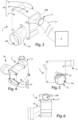
Figure 8A is a perspective view of the removing device ofFigure 3 , from which a portion of the casing of the removing device has been broken away to show the location of a first duct, through which machining chips may be drawn relative to an reference axis, around which a plurality of blades rotate; -
Figure 8B is a schematic view of the longitudinal section of a wall of the casing of the removing device ofFigure 3 ; -
Figure 9 shows the removing device ofFigure 3 in use; -
Figure 10 shows a variant of the removing device, in which the cutting elements for cutting the machining waste are positioned on respective side portions of respective blades, and each cutting element has a length greater than the length of the side portion of the respective blade on where it is located; -
Figure 11 shows a detail of the variant of the removing device ofFigure 10 , in which each cutting element protrudes with respect to a respective lateral portion of a blade in a radial direction; -
Figure 12 is a perspective view of a second embodiment of the edgebanding machine, in which the removing device is provided with a second duct through which further machining chips can be sucked; -
Figure 13 shows a detail of the removing device ofFigure 12 concerning the openings, at which the first duct and the second duct are positioned; -
Figure 14 shows the second duct in detail; -
Figure 15 is a front view of the second embodiment of the removing device ofFigure 12 . - In the various Figures, similar parts will be indicated with the same reference numbers.
- With reference to the Figures, a first embodiment of an
edgebanding machine 1 is described for applying a beading tape N to a panel P. - In particular, in the example described, the
edgebanding machine 1 is configured to apply a beading tape N to a panel P, when said panel P moves on a working plane along a forward direction. - Furthermore, in the example described, said panel P is a wooden panel.
- However, said panel can be made of a material other than wood.
- The
edgebanding machine 1 includes: - at least one working group R for working a portion of said edging tape N or a portion of the surface of said panel P, so that one or more machining chips F are created,
- at least one removing
device 2, for removing said one or more machining chips F by suction, wherein said removingdevice 2 is connected to said working group R and comprises:- a
casing 20, comprising afirst wall 21 and asecond wall 22, different from saidfirst wall 21, in which saidcasing 20 has afirst opening 20A, - arranged on said
first wall 21, and asecond opening 20B, arranged on saidsecond wall 22, to be connected in use to asuction device 6, - one or
more blades 24 arranged inside saidcasing 20 to rotate around a reference axis X in a rotation direction D, - at least one cutting
element 25 for cutting said one or more machining chips F.
- a
- Said removing
device 2 is configured in such a way that, when saidsuction device 6 is connected to said removingdevice 2, and is in use, said one or more machining chips F enter saidcasing 20, through saidfirst opening 20A of thecasing 20, along a first direction, which is perpendicular or substantially perpendicular to thefirst wall 21, are cut by said at least one cuttingelement 25, and exit from saidcasing 20, through thesecond opening 20B along a second direction, different from said first direction. - The machining chips F are generated by the need to make a surface of the edging tape N or a surface of the panel P a smooth surface, free from surface irregularities.
- In the example described, said working group R is an edge scraping group for finishing a lower end portion, which defines the lower edge of the edging tape N.
-
Figure 1 is a schematic view of anedgebanding machine 1 including the removingdevice 2. - In particular, a
suction device 6 is connected to the removingdevice 2. - In the example described, said removing
device 2 is connected to saidsuction device 6 via atube 61. - In particular, said
duct 61 is a flexible tube. - However, said tube need not be a flexible tube.
- In an alternative, said removing
device 2 can be connected to saidsuction device 6 via a plurality of ducts connected to each other. -
Figure 2 shows a detail referring to a compartment of theedgebanding machine 1, in which the removingdevice 2 is positioned. - With reference to the
casing 20, as already mentioned, saidcasing 20 comprises afirst wall 21, which is a front wall, and asecond wall 22, which is a side wall. - The
first wall 21 has a first surface orinternal surface 21A, and a second surface orexternal surface 21B, opposite to saidfirst surface 21A. - The
second wall 22 has a first surface orinternal surface 22A, and a second surface orexternal surface 22B, opposite to saidfirst surface 22A. - Furthermore, said
casing 20 comprises athird wall 23, which is a rear wall. - The
third wall 23 has a first surface orinternal surface 23A and a second surface orexternal surface 23B, opposite to saidfirst surface 23A. - The
second wall 22 extends from saidthird wall 23. - Furthermore, as already mentioned, said
casing 20 has afirst opening 20A, arranged on saidfirst wall 21, and asecond opening 20B, arranged on saidsecond wall 22, and saidsecond opening 20B is to be connected in use to saidsuction device 6. - With reference to the position of said
first opening 20A with respect to the reference axis X, saidfirst opening 20A has a center A, which is spaced with respect to said reference axis X. - In other words, the reference axis X does not pass through the center A of said
first opening 20A. - Said reference axis X is perpendicular or substantially perpendicular to the
first wall 21 of thecasing 20. - With reference to said one or
more blades 24, eachblade 24 comprises a respective firstlateral portion 24A facing saidfirst wall 21, in particular, theinternal surface 21A of saidfirst wall 21. - Each
blade 24 further comprises a respective secondlateral portion 24B, facing thesecond wall 22, in particular, theinternal surface 22A of saidsecond wall 22, as well as a respective thirdlateral portion 24C, facing thethird wall 23, in particular theinternal surface 23A of saidthird wall 23. - A respective
fourth side portion 24D of eachblade 24 contacts a housing 29 (in particular a portion of theouter surface 29A of said housing 29), in which themotor 28 for rotating theblades 24 is housed, as described further on. - Each
blade 24 further comprises a respective first face 241 and a respective second face 242, opposite to said first face 242. - With particular reference to the lateral portions mentioned above, the second
lateral portion 24B is perpendicular to the firstlateral portion 24A, the thirdlateral portion 24C is perpendicular to the secondlateral portion 24B, and opposite to the firstlateral portion 24A and thefourth lateral portion 24D is perpendicular to thethird side portion 24C and opposite thesecond side portion 24B. - In the first embodiment described, each
blade 24 has the shape of a respective rectangle in a longitudinal section. - Therefore, a first short side of the rectangle faces the first wall 21 (i.e., the
internal surface 21A of the first wall 21), a first long side of the rectangle faces the second wall 22 (i.e., theinternal surface 22A of the second wall 22), and a second short side of the rectangle (opposite the first short side) faces the third wall 23 (i.e., theinner surface 23A of the third wall 23). - The second long side of the rectangle contacts the
outer surface 29A of thehousing 29, in which themotor 28 is housed, as described further on. - Consequently, each cutting
element 25 is positioned on a respective first short side of said rectangle. - In the first embodiment described, the removing
device 2 comprises a plurality ofblades 24 and a plurality of cuttingelements 25. - It is preferable that the number of said cutting
elements 25 is equal to the number of saidblades 24. - With reference to said cutting
elements 25, each cuttingelement 25 is positioned on arespective blade 24. - In particular, each cutting
element 25 is positioned on a firstlateral portion 24A of arespective blade 24. - Advantageously, since each cutting
element 25 is positioned on a respective firstlateral portion 24A of arespective blade 24, the rotation of theblades 24 causes the rotation of the cuttingelements 25. - The machining chips F are cut by said cutting
elements 25, and each machining chip is divided into a plurality of portions generated by the cut performed by said cutting elements. - An advantage due to the presence of a plurality of cutting elements 25 (in particular a cutting
element 25 for each blade 24) is given by the fact that said machining chips F are shredded and the portions derived from said cut machining chips have reduced dimensions, so that thesecond opening 20B of thecasing 20 or the outlet duct 31 (mentioned later) is unlikely to be obstructed. - With particular reference to the
suction device 6, saidsuction device 6 is connected to thesecond opening 20B of thecasing 20, so that the machining chips F are sucked up and enter inside the removingdevice 2. - Although it is not necessary, the
suction device 6 can be included in saidedgebanding machine 1. - Furthermore, said removing
device 2 comprises afirst duct 26, which is a first inlet duct, through which the machining chips F enter thecasing 20 by means of suction. - Said
first duct 26 has: - an
input 26A for receiving said one or more machining chips F, and - an
outlet 26B arranged in correspondence with thefirst opening 20A of thecasing 20, so that said one or more machining chips F enter inside saidcasing 20. -
Figure 3 shows the removingdevice 2 and thesuction device 6 connected to the removingdevice 2. - In particular, the removing
device 2 comprises anoutlet duct 31, which is positioned at thesecond opening 20B of thecasing 20. - The
outlet duct 31 is connected to thesuction device 6 through saidduct 61, so that a quantity of air and a quantity of machining chips F come out of thecasing 20 of the removingdevice 2 when thesuction device 6 is in use. -
Figures 4 to 6 respectively show a rear perspective view, a front view, and a top view of the removingdevice 2. -
Figure 7A is an exploded view of the removingdevice 2. -
Figure 7B is a side view of the removingdevice 2 to show thesecond opening 20B on thecasing 20 of the removingdevice 2. -
Figure 7C shows ablade 24 in detail. - As shown in
Figure 7A , thefirst duct 26 is arranged on thecasing 20, in such a way that itsoutlet 26B is positioned in correspondence with thefirst opening 20A of thecasing 20. - The
blades 24 of said plurality of blades are arranged radially inside thecasing 20. - The rotation of said
blades 24 around said reference axis X (which is perpendicular or substantially perpendicular to the first wall 21) defines a circumference. - The
second opening 20B of the casing 20 (designed to allow the machining chips to exit the removing device 2) is arranged on a first plane, perpendicular to saidfirst wall 21, and thefirst opening 20A (designed to allow the chips to process entering the removingdevice 2 and connected to the first duct 26) is arranged on a second plane, perpendicular or substantially perpendicular to said first plane. - In the embodiment described, said
casing 20 is shaped in such a way that saidsecond opening 20B is above saidfirst opening 20A and said reference axis X. - Furthermore, the rotation direction D of the
blades 24 is a clockwise direction. - However, said
casing 20 can be shaped in such a way that saidsecond opening 20B is below saidfirst opening 20A and said reference axis X, without departing from the scope of the invention. - Furthermore, the rotation direction D of the
blades 24 can be a counterclockwise direction. - As shown in
Figures 8A and8B , thesecond wall 22 comprises anend portion 223D perpendicular or substantially perpendicular to thefirst wall 21 and arranged on a plane perpendicular to a straight line tangent to the circumference defined by the rotation of saidblades 24. - The
second opening 20B of thecasing 20 is arranged on saidend portion 223D. - With reference to the shape of the
second wall 22, saidsecond wall 22 is shaped in such a way that a space S, present between theblades 24 and theinternal surface 22A of thesecond wall 22, forms a channel for the passage of the machining chips, in which the width of said channel tends to increase in the rotation direction D of saidblades 25, and said channel ends on theend portion 223D of thesecond wall 22 of thecasing 20. - In other words, the channel is formed by the space S present between the circumference defined by the rotation of the
blades 24 and theinternal surface 22A of thesecond wall 22. - Advantageously, when the
blades 24 rotate in the rotation direction D, the machining chips F entering thecasing 20 are conveyed by the rotation of theblades 24, through said channel, towards thesecond opening 20B positioned on saidend portion 223D. - The distance between the
blades 24 and theinternal surface 22A of the second wall 22 (in particular the distance between the secondlateral portion 24B of theblades 24 and theinternal surface 22A of the second wall 22) tends to increase along the rotation direction D of theblades 24. - Consequently, the width of the space S between the
blades 24 and theinner surface 22A of thesecond wall 22 increases along the rotation direction D of the blades themselves towards theend portion 223D of thecasing 20. - In particular, the removing device has a radius of curvature CR defined by the distance between the reference axis X and the
internal surface 22A of thesecond wall 22. - As shown in particular in
Figure 8B , with reference to the shape of thesecond wall 22, in longitudinal section saidsecond wall 22 comprises not only theend portion 223D but also the following portions arranged in succession: - a
first portion 223A having a circular or substantially circular shape, and - a
second portion 223B having a curvilinear shape, different from said first curvilinear portion, - a
third portion 223C having a rectilinear shape, wherein saidthird portion 223C is arranged between saidsecond portion 223B and saidend portion 223D. - The
third portion 223C precedes, in the rotation direction D of the blades, theend portion 223D, on which thesecond opening 20B is arranged. - A
fifth portion 223E with a rectilinear shape connects saidend portion 223D to thefirst portion 223A. - Since the space S between the
blades 24 and theinner surface 22A of thesecond wall 22 tends to increase in the rotation direction D of theblades 24, the radius of curvature CR tends to increase in the rotation direction D of theblades 24 from saidfirst portion 223A to saidthird portion 223C. - The space S between the
blades 24 and theinner surface 22A of thesecond wall 22 comprises a plurality of portions: - a first portion of said space S is present between said
first portion 223A of saidsecond wall 22 and a first portion of said circumference, - a second portion of said space S is present between said
second portion 223B of saidsecond wall 22 and a second portion of said circumference, wherein said second portion of said space S is greater in terms of width than said first portion of said space S, and - a third portion of said space S is present between a
third portion 223C of saidsecond wall 22 and a third circumference portion, wherein said third portion of said space S is greater in terms of width than said second portion of said space S. - Consequently, the width of the channel formed by said space S gradually increases from the
first portion 223A to thethird portion 223C of thecasing 20. - With such a shape of the
second wall 22 it is possible to obtain a greater suction effect than with a suction effect of a known type of removing device. - However, said
second wall 22 can have any shape, for example a circular or substantially circular shape, without departing from the scope of the invention. - In the first embodiment described, the first
lateral portion 24A of eachblade 24 has a first length and each cuttingelement 25 has a second length equal to said first length, so that each cuttingelement 25 is completely overlapped on a respective firstlateral portion 24A of arespective blade 24. - Furthermore, the removing
device 2 comprises amotor 28, preferably an electric motor, for rotating saidblades 24 about said reference axis X. - Said removing
device 2 comprises ahousing 29, in which saidmotor 28 is housed, arranged inside thecasing 20 in such a way that said reference axis X passes through saidhousing 29. - In particular, said
housing 29 has a center and said reference axis X passes through said center. - Advantageously, the fact that the
motor 28 is housed in saidhousing 29 allows the removingdevice 2 to have a reduced size compared to a removing device of the known type. - Furthermore, as mentioned above, said
housing 29 has anouter surface 29A, and theblades 24 extend from saidhousing 29 outwards in a radial direction. - As stated above, each
blade 24 has aside portion 24D (i.e., the fourth side portion), which contacts theouter surface 29A of thehousing 29. - Accordingly, each
blade 24 extends from theouter surface 29A of thehousing 29 outward, in a radial direction. - In the first embodiment described, said
housing 29 occupies a substantially central position with respect to the casing. - Furthermore, in the first embodiment described, the
housing 29 has a cylindrical shape. -
Figure 9 shows an application example of the removingdevice 2 of theedgebanding machine 1. - In the example described, said machining unit R is an edge scraping group.
- An edging tape N has been applied to a side portion of a panel P and is finished by means of said edge scraping group R (whose respective cutting element can be seen in
Figure 9 ) to eliminate the surface irregularities present on the lower end portion of the edging tape itself. - In order to eliminate said surface irregularities, said edge scraping group R is equipped with a cutting element.
- The removal of said surface irregularities by means of said edge scraping group R creates a machining chip F, which is sucked up by the removing
device 2. - As can be seen from
Figure 9 , the removingdevice 2 is positioned close to the edging tape N applied on the panel P, so that each machining chip F easily enters the removingdevice 2 when thesuction device 6 is in use. - In the example described, a
suction head 260 is connected to theinlet 26A of thefirst duct 26 of the removingdevice 2 to facilitate the suction of the machining waste F. -
Figures 10 and 11 show a variant of theedgebanding machine 1, in which the first length of the firstlateral portions 24A of theblades 24 is different from the second length of the cuttingelements 24. - In particular, the first
lateral portion 24A of eachblade 24 has a first length and each cuttingelement 25 has a second length, greater than said first length, so that each cuttingelement 25 is partially superimposed on a respective firstlateral portion 24A of arespective blade 24. A portion of each cuttingelement 25 protrudes with respect to the respective firstlateral portion 24A of arespective blade 24 in a radial direction. -
Figures 12, 13, 14, and 15 show a second embodiment of theedgebanding machine 1, in which thecasing 20 of the removingdevice 2 has athird opening 20C arranged on thefirst wall 21. - Said removing
device 2 comprises asecond duct 27 that is a second inlet duct, through which one or more further machining chips can enter inside the removingdevice 2 by means of suction. - Said
second duct 27 is different from thefirst duct 26 and comprises: - an input 27A for receiving said one or more further machining chips F,
- an
outlet 27B arranged in correspondence with saidthird opening 20C, so that said one or more further machining chips enter inside saidcasing 20. - With reference to the
third opening 20C, saidthird opening 20C has a center C, different from the center A of thefirst opening 20A and spaced from said reference axis X. - In other words, the reference axis X does not pass through the center C of said
third opening 20C. - Although not shown in the Figures, said second inlet duct can be connected to said edge scraping group.
- Although not shown in the Figures, said
edgebanding machine 1 can comprise a cyclone separator for separating said one or more machining chips F from a quantity of air. - Said cyclone separator has at least a first inlet connected to said removing
device 2 and a first outlet to be connected in use to thesuction device 6. - In particular, said cyclone separator has a first outlet connected to the
outlet duct 31 of the removingdevice 2. - Furthermore, the
edgebanding machine 1 can include a container for collecting the machining chips F. - In particular, said cyclone separator has a second outlet (different from said first outlet), and said container has an inlet, connected to said second outlet, for receiving the machining chips which are separated by a quantity of air through the cyclone separator.
- After the machining chips are separated from said quantity of air by means of the cyclone separator, said machining chips F fall by gravity inside said container.
- Advantageously, the
edgebanding machine 1 object of the invention is equipped with a removingdevice 2 for effectively removing machining chips. - The structure of the removing
device 2 is simple and is designed for the strong suction power to be high. - A further advantage is given by the fact that the removing
device 2 has a small size. - The present invention has been described for illustrative but not limitative purposes, according to its preferred embodiments, but it is to be understood that modifications and/or changes can be introduced by those skilled in the art without departing from the relevant scope as defined in the enclosed claims.
Claims (14)
- Edgebanding machine (1) for applying an edging tape on at least one panel (P), comprising:- at least one working group (R) for working a portion of said edging tape (N) or a surface portion of said panel (P), so that one or more machining chips (F) are created,- at least one removing device (2) for removing said one or more machining chips (F) by suction, wherein said removing device (2) is connected to said working group (R) and comprises:whereina casing (20) comprising a first wall (21) and a second wall (22), different from said first wall (21), wherein said casing (20) has a first opening (20A), arranged on said first wall (21), and a second opening (20B), arranged on said second wall (22), to be connected in use with a suction device (6),one or more blades (24) arranged inside said casing (20) for rotating around a reference axis (X) in a rotation direction (D), said reference axis being perpendicular o substantially perpendicular to said first wall (21),at least one cutting element (25) for cutting said one or more machining chips (F), positioned on a blade (24) of said one or more blades (24), so that the rotation of said one or more blades (24) causes the rotation of said at least one cutting element (25),said first opening (20A) has a center (A) spaced from said reference axis (X),
whereinsaid removing device (2) is configured in such a way that, when said suction device (6) is connected to said removing device (2) and is in use, said one or more machining chips (F) enter said casing (20) through said first opening (20A) along a first direction being perpendicular o substantially perpendicular to said first wall (21), are cut by said at least one cutting element (4) and exit from said casing (20) trough said second opening (20B) along a second direction, different from said first direction. - Edgebanding machine (1) according to the previous claim, wherein said one or more blades (24) comprise a respective first side portion (24A) facing said first wall (21) of said casing (20) and said cutting element (25) is positioned on a first side portion (24A) of a blade (24) of said one or more blades (24).
- Edgebanding machine (1) according to the previous claim, wherein said edgebanding machine (1) comprises a plurality of blades (24) and a plurality of cutting elements (25) and each cutting element (25) of said plurality of cutting elements (25) is positioned on a respective first side portion (24A) of a respective blade (24) of said plurality of blades (24).
- Edgebanding machine (1) according to any one of the previous claims, wherein said removing device (2) comprises a first duct (26) having:an inlet (26A) for receiving said one or more machining chips (F), andan outlet (26B) arranged on said first opening (20A), so that said one ormore machining chips (F) enter inside said casing (20).
- Edgebanding machine (1) according to any one of the previous claims, whereinsaid one or more blades (24) are arranged radially inside said casing (20), so that the rotation of said one or more blades (24) defines a circumference,said second wall (22) comprises an inner surface (22A) as well as an end portion (223D) perpendicular or substantially perpendicular to said first wall (21) and arranged on a plane perpendicular to a straight line tangent to a circumference defined by the rotation of said one or more blades (24), wherein said second opening (20B) is arranged on said end portion (223D),said second wall (22) is shaped in such a way that a space (S) present between one or more blades (24) and said inner surface (22A) forms a channel, wherein the width of said channel tends to increase in the rotation direction (D) of said one or more blades (24) and said channel ends on said end portion (223D), so that, when said one or more blades (24) rotate in said rotation direction (D), said one or more machining chips (F) that enter inside said casing (20) are conveyed, through said channel, towards said second opening (20B) of said casing (20).
- Edgebanding machine (1) according to the previous claim, whereinsaid removing device (2) has a radius of curvature (CR) defined by a distance between said reference axis (X) and said inner surface (22A) of said second wall (22),
whereinsaid second wall (22) in longitudinal section comprises in succession:a first portion (223A) having a circular or substantially circular shape,a second portion (223B) having a curvilinear shape,a third portion (223C) having a rectilinear shape, in which said third portion (223C) is arranged between said second portion (223B) and said end portion (223D);whereinsaid radius of curvature (CR) tends to increase in said direction of rotation (D) from said first portion (223A) of said second wall (22) to said third portion (223C) of said second wall (22). - Edgebanding machine (1) according to any one of claims 1-6, wherein the respective first side portion (24A) of each blade (24) has a first length and each cutting element (25) has a second length equal to said first length, so that each cutting element (25) is completely overlapped on a respective side portion (24A) of a respective blade (24).
- Edgebanding machine (1) according to any one of claims 1-6, wherein the respective side portion (24A) of each blade (24) has a first length and each cutting element (25) has a second length greater than said first length, so that a portion of each cutting element (25) protruding with respect to the respective first side portion (24A) of a respective blade (24) in a radial direction.
- Edgebanding machine (1) according to any one of the previous claims, wherein said removing device (2) comprises a motor (28) for rotating one or more blades (24) around said reference axis (X).
- Edgebanding machine (1) according to the previous claim, wherein said removing device (2) comprises a housing (29) in which said motor (28) is housed, said housing being arranged inside said casing (20) in such a way that said reference axis (X) passes through said housing (29).
- Edgebanding machine (1) according to the previous claim, wherein said one or more blades (23) extend from said housing (29) outwards in a radial direction.
- Edgebanding machine (1) according to any one of the previous claims, wherein said working group (R) is an edge scraping group.
- Edgebanding machine (1) according to any one of the previous claims, whereinsaid edgebanding machine (1) comprises a cyclone separator for separating one or more machining chips (F) from a quantity of air,
whereinsaid cyclone separator has:at least one inlet for receiving said one or more machining chips, connected to said removing device (2), anda first outlet to be connected in use to said removing device (6). - Edgebanding machine (1) according to the previous claim, whereinsaid cyclone separator has a second outlet
whereinsaid edgebanding machine (1) comprises a container for collecting said one or more machining chips (F), wherein said container has an inlet, connected to said second outlet of said cyclone separator, so that, when said one or more machining chips (F) are separated from said quantity of air through said cyclone separator, said one or more machining chips (F) fall by gravity inside said container.
Applications Claiming Priority (1)
| Application Number | Priority Date | Filing Date | Title |
|---|---|---|---|
| IT102022000005315A IT202200005315A1 (en) | 2022-03-18 | 2022-03-18 | EDGE BANDING MACHINE EQUIPPED WITH A REMOVAL DEVICE TO REMOVE PROCESSING SCRAP. |
Publications (2)
| Publication Number | Publication Date |
|---|---|
| EP4245490A1 true EP4245490A1 (en) | 2023-09-20 |
| EP4245490B1 EP4245490B1 (en) | 2024-10-23 |
Family
ID=81927545
Family Applications (1)
| Application Number | Title | Priority Date | Filing Date |
|---|---|---|---|
| EP23162515.3A Active EP4245490B1 (en) | 2022-03-18 | 2023-03-17 | Edgebanding machine provided with a removing device for removing machining chips |
Country Status (2)
| Country | Link |
|---|---|
| EP (1) | EP4245490B1 (en) |
| IT (1) | IT202200005315A1 (en) |
Citations (2)
| Publication number | Priority date | Publication date | Assignee | Title |
|---|---|---|---|---|
| GB735839A (en) * | 1952-10-31 | 1955-08-31 | Kurt Zuckermann | Device for chip removal in woodworking machines |
| EP2186599A1 (en) * | 2008-11-18 | 2010-05-19 | SCM GROUP S.p.A. | Apparatus for removing machining chips |
-
2022
- 2022-03-18 IT IT102022000005315A patent/IT202200005315A1/en unknown
-
2023
- 2023-03-17 EP EP23162515.3A patent/EP4245490B1/en active Active
Patent Citations (2)
| Publication number | Priority date | Publication date | Assignee | Title |
|---|---|---|---|---|
| GB735839A (en) * | 1952-10-31 | 1955-08-31 | Kurt Zuckermann | Device for chip removal in woodworking machines |
| EP2186599A1 (en) * | 2008-11-18 | 2010-05-19 | SCM GROUP S.p.A. | Apparatus for removing machining chips |
Also Published As
| Publication number | Publication date |
|---|---|
| EP4245490B1 (en) | 2024-10-23 |
| IT202200005315A1 (en) | 2023-09-18 |
Similar Documents
| Publication | Publication Date | Title |
|---|---|---|
| US5931072A (en) | Circular saw with an improved dust collector | |
| KR101587767B1 (en) | Oil mist collector | |
| US20160158680A1 (en) | Centripetal Separation System for Cleaning Particulate-Pervaded Air or Gas | |
| TWI574808B (en) | Table saw dust extraction assembly | |
| US20050247463A1 (en) | Hand-held machine tool comprising a dust box | |
| CN101660535A (en) | Centrifugal fan and air fluid machinery using the same | |
| CN104148720B (en) | Manual planer | |
| US4613261A (en) | Router tool | |
| CN101698131A (en) | Air treatment equipment | |
| US2733000A (en) | sparklin | |
| EP4245490B1 (en) | Edgebanding machine provided with a removing device for removing machining chips | |
| CN102654140A (en) | Electric air blower and electric dust collector provided with the same | |
| US20190134647A1 (en) | Cyclone type dust collecting apparatus | |
| WO2018083783A1 (en) | Electrically operated air blower, electric vacuum cleaner, and hand dryer | |
| US5332163A (en) | Motor-driven machine | |
| EP3715032B1 (en) | Reciprocating saw | |
| EP2022602B1 (en) | Device for removing chips in machine tools | |
| EP3064301B1 (en) | Portable working machine | |
| CN108284488B (en) | Band saw machine | |
| US9073058B2 (en) | Wood chipping apparatus and method | |
| JP6076032B2 (en) | Oil mist removal device | |
| CN201551935U (en) | Air treatment device | |
| CN111801040B (en) | Dust collecting device and electric dust collector | |
| CN111787840B (en) | Dust collectors and electric vacuum cleaners | |
| JP5784066B2 (en) | Centrifugal impeller, electric blower and vacuum cleaner |
Legal Events
| Date | Code | Title | Description |
|---|---|---|---|
| PUAI | Public reference made under article 153(3) epc to a published international application that has entered the european phase |
Free format text: ORIGINAL CODE: 0009012 |
|
| STAA | Information on the status of an ep patent application or granted ep patent |
Free format text: STATUS: THE APPLICATION HAS BEEN PUBLISHED |
|
| AK | Designated contracting states |
Kind code of ref document: A1 Designated state(s): AL AT BE BG CH CY CZ DE DK EE ES FI FR GB GR HR HU IE IS IT LI LT LU LV MC ME MK MT NL NO PL PT RO RS SE SI SK SM TR |
|
| STAA | Information on the status of an ep patent application or granted ep patent |
Free format text: STATUS: REQUEST FOR EXAMINATION WAS MADE |
|
| 17P | Request for examination filed |
Effective date: 20240131 |
|
| RBV | Designated contracting states (corrected) |
Designated state(s): AL AT BE BG CH CY CZ DE DK EE ES FI FR GB GR HR HU IE IS IT LI LT LU LV MC ME MK MT NL NO PL PT RO RS SE SI SK SM TR |
|
| GRAP | Despatch of communication of intention to grant a patent |
Free format text: ORIGINAL CODE: EPIDOSNIGR1 |
|
| STAA | Information on the status of an ep patent application or granted ep patent |
Free format text: STATUS: GRANT OF PATENT IS INTENDED |
|
| INTG | Intention to grant announced |
Effective date: 20240524 |
|
| GRAS | Grant fee paid |
Free format text: ORIGINAL CODE: EPIDOSNIGR3 |
|
| GRAA | (expected) grant |
Free format text: ORIGINAL CODE: 0009210 |
|
| STAA | Information on the status of an ep patent application or granted ep patent |
Free format text: STATUS: THE PATENT HAS BEEN GRANTED |
|
| AK | Designated contracting states |
Kind code of ref document: B1 Designated state(s): AL AT BE BG CH CY CZ DE DK EE ES FI FR GB GR HR HU IE IS IT LI LT LU LV MC ME MK MT NL NO PL PT RO RS SE SI SK SM TR |
|
| REG | Reference to a national code |
Ref country code: GB Ref legal event code: FG4D |
|
| REG | Reference to a national code |
Ref country code: CH Ref legal event code: EP |
|
| REG | Reference to a national code |
Ref country code: DE Ref legal event code: R096 Ref document number: 602023000795 Country of ref document: DE |
|
| REG | Reference to a national code |
Ref country code: IE Ref legal event code: FG4D |
|
| REG | Reference to a national code |
Ref country code: LT Ref legal event code: MG9D |
|
| REG | Reference to a national code |
Ref country code: NL Ref legal event code: MP Effective date: 20241023 |
|
| PG25 | Lapsed in a contracting state [announced via postgrant information from national office to epo] |
Ref country code: NL Free format text: LAPSE BECAUSE OF FAILURE TO SUBMIT A TRANSLATION OF THE DESCRIPTION OR TO PAY THE FEE WITHIN THE PRESCRIBED TIME-LIMIT Effective date: 20241023 |
|
| PG25 | Lapsed in a contracting state [announced via postgrant information from national office to epo] |
Ref country code: NL Free format text: LAPSE BECAUSE OF FAILURE TO SUBMIT A TRANSLATION OF THE DESCRIPTION OR TO PAY THE FEE WITHIN THE PRESCRIBED TIME-LIMIT Effective date: 20241023 |
|
| PG25 | Lapsed in a contracting state [announced via postgrant information from national office to epo] |
Ref country code: HR Free format text: LAPSE BECAUSE OF FAILURE TO SUBMIT A TRANSLATION OF THE DESCRIPTION OR TO PAY THE FEE WITHIN THE PRESCRIBED TIME-LIMIT Effective date: 20241023 Ref country code: IS Free format text: LAPSE BECAUSE OF FAILURE TO SUBMIT A TRANSLATION OF THE DESCRIPTION OR TO PAY THE FEE WITHIN THE PRESCRIBED TIME-LIMIT Effective date: 20250223 Ref country code: PT Free format text: LAPSE BECAUSE OF FAILURE TO SUBMIT A TRANSLATION OF THE DESCRIPTION OR TO PAY THE FEE WITHIN THE PRESCRIBED TIME-LIMIT Effective date: 20250224 |
|
| PG25 | Lapsed in a contracting state [announced via postgrant information from national office to epo] |
Ref country code: FI Free format text: LAPSE BECAUSE OF FAILURE TO SUBMIT A TRANSLATION OF THE DESCRIPTION OR TO PAY THE FEE WITHIN THE PRESCRIBED TIME-LIMIT Effective date: 20241023 |
|
| PG25 | Lapsed in a contracting state [announced via postgrant information from national office to epo] |
Ref country code: BG Free format text: LAPSE BECAUSE OF FAILURE TO SUBMIT A TRANSLATION OF THE DESCRIPTION OR TO PAY THE FEE WITHIN THE PRESCRIBED TIME-LIMIT Effective date: 20241023 |
|
| PG25 | Lapsed in a contracting state [announced via postgrant information from national office to epo] |
Ref country code: ES Free format text: LAPSE BECAUSE OF FAILURE TO SUBMIT A TRANSLATION OF THE DESCRIPTION OR TO PAY THE FEE WITHIN THE PRESCRIBED TIME-LIMIT Effective date: 20241023 |
|
| PG25 | Lapsed in a contracting state [announced via postgrant information from national office to epo] |
Ref country code: NO Free format text: LAPSE BECAUSE OF FAILURE TO SUBMIT A TRANSLATION OF THE DESCRIPTION OR TO PAY THE FEE WITHIN THE PRESCRIBED TIME-LIMIT Effective date: 20250123 |
|
| PG25 | Lapsed in a contracting state [announced via postgrant information from national office to epo] |
Ref country code: LV Free format text: LAPSE BECAUSE OF FAILURE TO SUBMIT A TRANSLATION OF THE DESCRIPTION OR TO PAY THE FEE WITHIN THE PRESCRIBED TIME-LIMIT Effective date: 20241023 Ref country code: GR Free format text: LAPSE BECAUSE OF FAILURE TO SUBMIT A TRANSLATION OF THE DESCRIPTION OR TO PAY THE FEE WITHIN THE PRESCRIBED TIME-LIMIT Effective date: 20250124 |
|
| PG25 | Lapsed in a contracting state [announced via postgrant information from national office to epo] |
Ref country code: PL Free format text: LAPSE BECAUSE OF FAILURE TO SUBMIT A TRANSLATION OF THE DESCRIPTION OR TO PAY THE FEE WITHIN THE PRESCRIBED TIME-LIMIT Effective date: 20241023 |
|
| PG25 | Lapsed in a contracting state [announced via postgrant information from national office to epo] |
Ref country code: RS Free format text: LAPSE BECAUSE OF FAILURE TO SUBMIT A TRANSLATION OF THE DESCRIPTION OR TO PAY THE FEE WITHIN THE PRESCRIBED TIME-LIMIT Effective date: 20250123 |
|
| PG25 | Lapsed in a contracting state [announced via postgrant information from national office to epo] |
Ref country code: SM Free format text: LAPSE BECAUSE OF FAILURE TO SUBMIT A TRANSLATION OF THE DESCRIPTION OR TO PAY THE FEE WITHIN THE PRESCRIBED TIME-LIMIT Effective date: 20241023 |
|
| PG25 | Lapsed in a contracting state [announced via postgrant information from national office to epo] |
Ref country code: DK Free format text: LAPSE BECAUSE OF FAILURE TO SUBMIT A TRANSLATION OF THE DESCRIPTION OR TO PAY THE FEE WITHIN THE PRESCRIBED TIME-LIMIT Effective date: 20241023 |
|
| PGFP | Annual fee paid to national office [announced via postgrant information from national office to epo] |
Ref country code: IT Payment date: 20250331 Year of fee payment: 3 |
|
| PG25 | Lapsed in a contracting state [announced via postgrant information from national office to epo] |
Ref country code: EE Free format text: LAPSE BECAUSE OF FAILURE TO SUBMIT A TRANSLATION OF THE DESCRIPTION OR TO PAY THE FEE WITHIN THE PRESCRIBED TIME-LIMIT Effective date: 20241023 |
|
| PG25 | Lapsed in a contracting state [announced via postgrant information from national office to epo] |
Ref country code: RO Free format text: LAPSE BECAUSE OF FAILURE TO SUBMIT A TRANSLATION OF THE DESCRIPTION OR TO PAY THE FEE WITHIN THE PRESCRIBED TIME-LIMIT Effective date: 20241023 |
|
| REG | Reference to a national code |
Ref country code: DE Ref legal event code: R097 Ref document number: 602023000795 Country of ref document: DE |
|
| PG25 | Lapsed in a contracting state [announced via postgrant information from national office to epo] |
Ref country code: SK Free format text: LAPSE BECAUSE OF FAILURE TO SUBMIT A TRANSLATION OF THE DESCRIPTION OR TO PAY THE FEE WITHIN THE PRESCRIBED TIME-LIMIT Effective date: 20241023 |
|
| PG25 | Lapsed in a contracting state [announced via postgrant information from national office to epo] |
Ref country code: CZ Free format text: LAPSE BECAUSE OF FAILURE TO SUBMIT A TRANSLATION OF THE DESCRIPTION OR TO PAY THE FEE WITHIN THE PRESCRIBED TIME-LIMIT Effective date: 20241023 |
|
| PLBE | No opposition filed within time limit |
Free format text: ORIGINAL CODE: 0009261 |
|
| STAA | Information on the status of an ep patent application or granted ep patent |
Free format text: STATUS: NO OPPOSITION FILED WITHIN TIME LIMIT |
|
| PG25 | Lapsed in a contracting state [announced via postgrant information from national office to epo] |
Ref country code: SE Free format text: LAPSE BECAUSE OF FAILURE TO SUBMIT A TRANSLATION OF THE DESCRIPTION OR TO PAY THE FEE WITHIN THE PRESCRIBED TIME-LIMIT Effective date: 20241023 |
|
| 26N | No opposition filed |
Effective date: 20250724 |
|
| PG25 | Lapsed in a contracting state [announced via postgrant information from national office to epo] |
Ref country code: MC Free format text: LAPSE BECAUSE OF FAILURE TO SUBMIT A TRANSLATION OF THE DESCRIPTION OR TO PAY THE FEE WITHIN THE PRESCRIBED TIME-LIMIT Effective date: 20241023 |
|
| REG | Reference to a national code |
Ref country code: AT Ref legal event code: UEP Ref document number: 1734484 Country of ref document: AT Kind code of ref document: T Effective date: 20241023 |
|
| PG25 | Lapsed in a contracting state [announced via postgrant information from national office to epo] |
Ref country code: LU Free format text: LAPSE BECAUSE OF NON-PAYMENT OF DUE FEES Effective date: 20250317 |
|
| REG | Reference to a national code |
Ref country code: BE Ref legal event code: MM Effective date: 20250331 |
|
| PG25 | Lapsed in a contracting state [announced via postgrant information from national office to epo] |
Ref country code: FR Free format text: LAPSE BECAUSE OF NON-PAYMENT OF DUE FEES Effective date: 20250331 |
|
| PG25 | Lapsed in a contracting state [announced via postgrant information from national office to epo] |
Ref country code: BE Free format text: LAPSE BECAUSE OF NON-PAYMENT OF DUE FEES Effective date: 20250331 |
|
| PG25 | Lapsed in a contracting state [announced via postgrant information from national office to epo] |
Ref country code: IE Free format text: LAPSE BECAUSE OF NON-PAYMENT OF DUE FEES Effective date: 20250317 |
|
| PGFP | Annual fee paid to national office [announced via postgrant information from national office to epo] |
Ref country code: DE Payment date: 20260320 Year of fee payment: 4 |
|
| PGFP | Annual fee paid to national office [announced via postgrant information from national office to epo] |
Ref country code: AT Payment date: 20260301 Year of fee payment: 4 |