EP4245324A2 - Hand-held sterile connection device, system, and method of use - Google Patents
Hand-held sterile connection device, system, and method of use Download PDFInfo
- Publication number
- EP4245324A2 EP4245324A2 EP23161102.1A EP23161102A EP4245324A2 EP 4245324 A2 EP4245324 A2 EP 4245324A2 EP 23161102 A EP23161102 A EP 23161102A EP 4245324 A2 EP4245324 A2 EP 4245324A2
- Authority
- EP
- European Patent Office
- Prior art keywords
- holder
- sterilization
- actuator
- connectors
- reusable
- Prior art date
- Legal status (The legal status is an assumption and is not a legal conclusion. Google has not performed a legal analysis and makes no representation as to the accuracy of the status listed.)
- Granted
Links
Images




Classifications
-
- A—HUMAN NECESSITIES
- A61—MEDICAL OR VETERINARY SCIENCE; HYGIENE
- A61L—METHODS OR APPARATUS FOR STERILISING MATERIALS OR OBJECTS IN GENERAL; DISINFECTION, STERILISATION OR DEODORISATION OF AIR; CHEMICAL ASPECTS OF BANDAGES, DRESSINGS, ABSORBENT PADS OR SURGICAL ARTICLES; MATERIALS FOR BANDAGES, DRESSINGS, ABSORBENT PADS OR SURGICAL ARTICLES
- A61L2/00—Disinfection or sterilisation of materials or objects, in general; Accessories therefor
- A61L2/02—Disinfection or sterilisation of materials or objects, in general; Accessories therefor using physical processes
- A61L2/08—Radiation
- A61L2/10—Ultraviolet [UV] radiation
-
- A—HUMAN NECESSITIES
- A61—MEDICAL OR VETERINARY SCIENCE; HYGIENE
- A61L—METHODS OR APPARATUS FOR STERILISING MATERIALS OR OBJECTS IN GENERAL; DISINFECTION, STERILISATION OR DEODORISATION OF AIR; CHEMICAL ASPECTS OF BANDAGES, DRESSINGS, ABSORBENT PADS OR SURGICAL ARTICLES; MATERIALS FOR BANDAGES, DRESSINGS, ABSORBENT PADS OR SURGICAL ARTICLES
- A61L2/00—Disinfection or sterilisation of materials or objects, in general; Accessories therefor
- A61L2/24—Apparatus using programmed or automatic operation
-
- A—HUMAN NECESSITIES
- A61—MEDICAL OR VETERINARY SCIENCE; HYGIENE
- A61M—DEVICES FOR INTRODUCING MEDIA INTO, OR ONTO, THE BODY; DEVICES FOR TRANSDUCING BODY MEDIA OR FOR TAKING MEDIA FROM THE BODY; DEVICES FOR PRODUCING OR ENDING SLEEP OR STUPOR
- A61M39/00—Tubes, tube connectors, tube couplings, valves, access sites or the like, specially adapted for medical use
- A61M39/10—Tube connectors or tube couplings
- A61M39/16—Tube connectors or tube couplings having provision for disinfection or sterilisation
- A61M39/18—Methods or apparatus for making the connection under sterile conditions, i.e. sterile docking
-
- A—HUMAN NECESSITIES
- A61—MEDICAL OR VETERINARY SCIENCE; HYGIENE
- A61L—METHODS OR APPARATUS FOR STERILISING MATERIALS OR OBJECTS IN GENERAL; DISINFECTION, STERILISATION OR DEODORISATION OF AIR; CHEMICAL ASPECTS OF BANDAGES, DRESSINGS, ABSORBENT PADS OR SURGICAL ARTICLES; MATERIALS FOR BANDAGES, DRESSINGS, ABSORBENT PADS OR SURGICAL ARTICLES
- A61L2103/00—Materials or objects being the target of disinfection or sterilisation
- A61L2103/15—Laboratory, medical or dentistry appliances, e.g. catheters or sharps
-
- A—HUMAN NECESSITIES
- A61—MEDICAL OR VETERINARY SCIENCE; HYGIENE
- A61L—METHODS OR APPARATUS FOR STERILISING MATERIALS OR OBJECTS IN GENERAL; DISINFECTION, STERILISATION OR DEODORISATION OF AIR; CHEMICAL ASPECTS OF BANDAGES, DRESSINGS, ABSORBENT PADS OR SURGICAL ARTICLES; MATERIALS FOR BANDAGES, DRESSINGS, ABSORBENT PADS OR SURGICAL ARTICLES
- A61L2202/00—Aspects relating to methods or apparatus for disinfecting or sterilising materials or objects
- A61L2202/10—Apparatus features
- A61L2202/11—Apparatus for generating biocidal substances, e.g. vaporisers, UV lamps
-
- A—HUMAN NECESSITIES
- A61—MEDICAL OR VETERINARY SCIENCE; HYGIENE
- A61L—METHODS OR APPARATUS FOR STERILISING MATERIALS OR OBJECTS IN GENERAL; DISINFECTION, STERILISATION OR DEODORISATION OF AIR; CHEMICAL ASPECTS OF BANDAGES, DRESSINGS, ABSORBENT PADS OR SURGICAL ARTICLES; MATERIALS FOR BANDAGES, DRESSINGS, ABSORBENT PADS OR SURGICAL ARTICLES
- A61L2202/00—Aspects relating to methods or apparatus for disinfecting or sterilising materials or objects
- A61L2202/10—Apparatus features
- A61L2202/12—Apparatus for isolating biocidal substances from the environment
- A61L2202/121—Sealings, e.g. doors, covers, valves, sluices
-
- A—HUMAN NECESSITIES
- A61—MEDICAL OR VETERINARY SCIENCE; HYGIENE
- A61L—METHODS OR APPARATUS FOR STERILISING MATERIALS OR OBJECTS IN GENERAL; DISINFECTION, STERILISATION OR DEODORISATION OF AIR; CHEMICAL ASPECTS OF BANDAGES, DRESSINGS, ABSORBENT PADS OR SURGICAL ARTICLES; MATERIALS FOR BANDAGES, DRESSINGS, ABSORBENT PADS OR SURGICAL ARTICLES
- A61L2202/00—Aspects relating to methods or apparatus for disinfecting or sterilising materials or objects
- A61L2202/10—Apparatus features
- A61L2202/12—Apparatus for isolating biocidal substances from the environment
- A61L2202/122—Chambers for sterilisation
-
- A—HUMAN NECESSITIES
- A61—MEDICAL OR VETERINARY SCIENCE; HYGIENE
- A61L—METHODS OR APPARATUS FOR STERILISING MATERIALS OR OBJECTS IN GENERAL; DISINFECTION, STERILISATION OR DEODORISATION OF AIR; CHEMICAL ASPECTS OF BANDAGES, DRESSINGS, ABSORBENT PADS OR SURGICAL ARTICLES; MATERIALS FOR BANDAGES, DRESSINGS, ABSORBENT PADS OR SURGICAL ARTICLES
- A61L2202/00—Aspects relating to methods or apparatus for disinfecting or sterilising materials or objects
- A61L2202/10—Apparatus features
- A61L2202/15—Biocide distribution means, e.g. nozzles, pumps, manifolds, fans, baffles, sprayers
-
- A—HUMAN NECESSITIES
- A61—MEDICAL OR VETERINARY SCIENCE; HYGIENE
- A61L—METHODS OR APPARATUS FOR STERILISING MATERIALS OR OBJECTS IN GENERAL; DISINFECTION, STERILISATION OR DEODORISATION OF AIR; CHEMICAL ASPECTS OF BANDAGES, DRESSINGS, ABSORBENT PADS OR SURGICAL ARTICLES; MATERIALS FOR BANDAGES, DRESSINGS, ABSORBENT PADS OR SURGICAL ARTICLES
- A61L2202/00—Aspects relating to methods or apparatus for disinfecting or sterilising materials or objects
- A61L2202/10—Apparatus features
- A61L2202/16—Mobile applications, e.g. portable devices, trailers, devices mounted on vehicles
Definitions
- the present disclosure is directed to a hand-held sterilization device, system, and a method for transferring fluid in a sterile manner. More particularly, the present disclosure is directed to a hand-held sterilization device and system, and a method for creating temporary sterile fluid flow path connections.
- Fluid flow processing systems or assemblies for transferring or dispensing a fluid (liquid) from a source container to one or more receiving containers or receptacles are used in a variety of medical and non-medical applications.
- the transfer of fluid must be carried out in a sterile manner, i.e., without exposing the fluids or the open ends of the tubing that carries the fluid to the outside environment.
- a sterile manner i.e., without exposing the fluids or the open ends of the tubing that carries the fluid to the outside environment.
- This is the collection of multiple samples from a large volume of a collected biological fluid.
- sterile connections are typically made by joining the ends of connecting tubing associated with a respective part of a processing system, for instance, by cutting, then melting the tubes together creating a fluid pathway, and then sterilizing the pathway.
- a device that creates a sterile connection is the TSCD-II sterile tubing welder, available from Terumo Medical Corporation.
- This device uses a heated cutting element to sever and melt the ends of tubing using a heated wafer, which are joined together after the cutting element is removed. The heated wafer creates an aseptic connection. Aspects of this device are disclosed in U.S. Patent Application Publication No. 2020/0047423 .
- tubing welding devices are benchtop devices that require connections to be made wherever the device is located and not necessarily where the transfer of fluid is to occur.
- benchtop models are not well suited to be moved from place to place.
- a hand-held sterilization device in one aspect, includes a sterilization chamber defined by a base and a lid and at least one holder within the sterilization chamber.
- the device includes a handle supporting the sterilization chamber, a light source associated with the sterilization chamber, and an actuator configured to move the at least one holder.
- a system for providing a sterile fluid pathway connection includes a first reusable tube connector configured to receive a first tube and a second reusable tube connector configured to receive a second tube and a hand-held sterilization device.
- the sterilization device of the system includes a sterilization chamber defined by a base and a lid.
- the chamber includes at least one holder, configured to receive one of the first or second reusable connectors.
- the hand-held sterilization device includes a handle supporting the sterilization chamber, a light source associated with the sterilization chamber, and an actuator configured to move the at least one holder.
- a method for transferring fluid in a sterile manner includes attaching an open first end of a tube to a first tube connector wherein the tube includes a second end in flow communication with a source of fluid, and attaching an open first end of a second tube to a second tube connector.
- the first and second connectors are located within a sterilization chamber carried by a handle of a hand-held device, wherein the chamber receives light from a light source associated with the device.
- the method further includes temporarily joining the first and second connectors to establish a flow path between the first and second tubes, exposing at least the flow path to a sterilizing light from said light source for a selected period of time, opening the flow path and flowing fluid from said source of fluid through the flow path, and separating the first and second connectors.
- Fig. 1 shows a hand-held sterilization device 10 in accordance with the present disclosure.
- the sterilization device 10 includes a sterilization chamber 12.
- the sterilization chamber 12 is defined by a base 14 and a lid 16.
- the sterilization device 10 further includes an elongated handle 18 and an actuator 20 configured for one-handed operation by user.
- the hand-held nature of the sterilization device 10 allows a user to transport the device 10 to wherever a sterile connection needs to be made.
- a portable device as disclosed herein provides greater flexibility in choosing a location within a hospital, blood center, or laboratory, for performing the sterile transfer of fluids.
- Sterilization device 10 may be used to sterilize reusable connectors shown and described below.
- the reusable connectors may be attached to tubing associated with two different parts of a fluid kit, circuit, or system.
- Using reusable connectors allows a user to make a temporary fluid connection between two tubes without physically welding the tubes together or otherwise making an irreversible permanent connection.
- the tubing and fluid kit associated with the respective tubing, including the pre-attached reusable connector will be sterilized prior to making a connection.
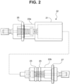
- Fig. 2 shows a first and second reusable connector, 22a and 22b, respectively.
- the connectors are configured to allow for attachment of open tubing ends to the connectors to create a fluid pathway between the tubing when the connectors are temporarily secured to one another.
- the reusable connectors 22a and 22b may be attached to a tube using a barb or other interference-type fitting.
- Other methods known in the art may be used to connect the reusable connectors to tubing without departing from the scope of the disclosure.
- the reusable connectors 22a and 22b may be connected by, for example, but not limited to, using a luer fitting or gluing the tube to the end of the reusable connector.
- the outer surfaces of reusable connectors may be, but are not limited to being, made of a transparent material.
- the reusable connectors are made of a transparent material that can be penetrated by light from the sterilizing light source.
- the material may be transparent to at least UV-C light.
- the reusable connectors may be made of a cyclic olefin copolymer (COC).
- COC cyclic olefin copolymer
- the first and second reusable connectors 22a and 22b are a female and male connectors, respectively.
- Reusable connectors 22a, 22b include spring activated plungers movably disposed within each connector, respectively. In an uncompressed state, the spring plunger presses a sealing member such as an O-ring, acting as a face seal, against the respective opening of each connector 22a and 22b to close the fluid path within each connector 22a, 22b.
- O-rings 23 associated with the outside of the second reusable connector 22b create an air-tight seal within a receiving chamber 21 of the first reusable connector 22a configured to receive the second reusable connector 22b.
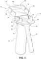
- Fig. 3 shows a hand-held sterile connection device 10 with lid 16 in an open configuration.
- lid 16 may include a top wall or roof 16a and sidewalls 16b, 16c, 16d and 16e. As shown in Fig. 3 , at least side walls 16b, 16c and 16d depend downwardly from and move with top wall 16a.
- One of the side walls e.g., 16e may be permanently attached to an edge of base 14 and may be hingedly attached to an edge of top wall 16a of lid 16, allowing lid 16 to easily flip between an open and closed position without interference from device components (described below) carried by base 14 and also for convenient mounting of connectors 22a and 22b within sterilization chamber 12.
- the lid 16 may be a completely detachable lid and may be secured in a snap-fit manner to base 14. Other lids known in the art may be used without departing from the scope of the disclosure.
- the footprint of lid 16 may correspond with the perimeter of the base 14. For instance, if the perimeter of the base 14 is a rectangular shape, the footprint of lid 16 will be a corresponding rectangular shape to cover the entirety of the base 14.
- Lid 16 may include slots 24 in opposed sidewalls 16b and 16c configured to receive tubing when lid 16 is placed in its closed configuration.
- sterilization device 10 may include one or more holders 26 carried by base 14 configured to receive connectors 22a, 22b.
- the base unit includes two holders 26 initially positioned at opposite ends of base 14 within sterilization chamber 12.
- holders 26 are positioned on either side of a light source 28 in base 14.
- the holders 26 may be configured to receive a reusable connector(s) 22a, 22b.
- holders 26 may include slots such as U-shaped slots 29 for receiving collars 25, 27 (shown in Fig. 2 ) of connectors 22a, 22b.
- holders 26 are moveable towards each other. Movement of holders 26 may be initiated by actuator 20 coupled to holders 26.
- the actuator 20 may be a trigger.
- the actuator 20 may be a button or a set of buttons. For example, by pressing actuator/trigger 20 to a first position, holders 26 may be moved towards one another to a first position, connecting the reusable connectors 22a, 22b above the light source 28. Again, by moving actuator 20 to a second position, the moveable holders 26 may be moved even closer to one another, opening a fluid pathway between the reusable connectors 22a, 22b.
- the actuator 20 may be attached to the device 10 using a pin and hole system.
- the actuator 20 may contain a hole in the upper portion. A pin is then inserted through the hole to secure the actuator 20 to the handle 18. This allows the actuator 20 to rotate about the pin in the handle 18. Other methods of attaching the actuator 20 to the device may be used without departing from the scope of the disclosure.
- the actuator 20 is configured to move the holders 26 using a linkage system that will be known to those of skill in the art.
- actuator 20 may turn a gear which engages two racks configured to move holders 26 closer together.
- the actuator 20 may turn a cam which displaces internal stops to allow for linear springs to move the holders 26 towards one another.
- the actuator 20 could drive two lead screws or roller screws together to move the connectors 26 towards one another.
- the actuator 20 may be a button that sends a signal to a controller configured to move the holders 26.
- the controller may control motor driven movements within the device 10.
- a single button may be used to move the holders 26.
- the button may be pressed a first time to send a first signal to the controller to move the holders 26 to a first position above the light source 28.
- the light source 28 may be activated for a preset amount of time.
- the button may then be pressed a second time to send a second signal to the controller to move the holders 26 into the second position, opening the fluid pathway.
- the button may activate the sterilization process by activating a controller associated with a timer.
- the controller may move the holders 26 into a first position where they are sterilized for a preset amount of time. After sufficient sterilization, the controller may automatically move the holders 26 to a second position, opening the fluid pathway. The controller may then return holders 26 to their initial positions after a preset amount of time or by the user pressing the button a second time sending a second signal to the controller.
- a two-button system may be utilized, where a first button may be pressed to move the holders 26 into the first position, and the second button may be pressed to move the holders 26 into the second position.
- Sterilization chamber 12 includes or may be otherwise associated with a light source for providing sterilizing light to sterilization chamber 12.
- the light source 28 may be housed within base unit 14 and/or upper region of handle 18, such that the connectors 22a, 22b are irradiated from below.
- the inner surface of top wall 16a of lid 16 may be coated with a reflective material to provide more uniform irradiation to connectors 22a, 22b and the flow path established by the connectors.
- inner surface 16a may have a mirror finish.
- the light source 28 is located in the center of the base 14. In another embodiment, the light source 28 may span the entire area between the holders 26.
- the light source 28 may be placed anywhere inside the sterilization chamber 12, such that the reusable connectors 22a, 22b will be irradiated by the light source 28.
- the light source 28 could be associated with the lid 16, such that the light source 28 would irradiate the reusable connectors 22a, 22b from above.
- the light source 28 may be, but is not limited to being, an LED light source emitting UV-C light. In an embodiment, the light source 28 may be a UV-C germicidal bulb. Other sterilizing light sources known in the art may be used without departing from the scope of the disclosure.
- Device 10 may further include a power supply for powering light source 28. Power supply may be housed in handle 18. In one embodiment, the power supply may be a rechargeable battery. In another embodiment, the power supply may be a cord to be plugged into an electrical socket in a wall. The cord may be long enough to allow for mobile use of the device 10.
- the hand-held device 10 may be used to create a temporary sterile connection flow path between a source of fluid and other containers. For instance, it may be desirable to transfer fluid from a source container with a large volume of fluid to many smaller containers. In another aspect, the device may be used to take samples from large biological processes requiring sterile pathways.
- Fig. 4 Sterilization of connectors using hand-held device 10 is further shown in Fig. 4 , with steps 40-48 setting forth the connection and sterilization steps.
- the user will attach a first end of a first tube 30a to the first reusable connector 22a and a first end of a second tube 30b to the second connector 22b.
- the connectors 22a, 22b may be attached to the tube using a barb fitting located at the proximal end of the connector.
- Other methods known in the art may be used to connect the reusable connectors to tubing without departing from the scope of the disclosure.
- the reusable connectors 22a and 22b may be connected by, for example, but not limited to, using a luer fitting or gluing the tube to the end of the reusable connector.
- the reusable connectors 22a and 22b may be pre-attached to a short length of tubing to enable the reusable connectors 22a and 22b to be sterile docked to the desired tubing set. This would allow for the reusable connectors 22a and 22b and the pre-attached tubing to be sterilized during manufacturing and to ensure a closed system when using the device 10.
- the connectors 22a, 22b are located within the sterilization chamber 12 by mounting them into a holder 26, as seen in Fig. 5 .
- the first tubing connector 22a is placed in a first holder 26 within the sterilization chamber 12 and the second connector 22b is placed in a second holder 26 within the sterilization chamber 12.
- the lid 16 of the separation chamber 12 may be closed.
- the connectors 22a, 22b are temporarily joined together.
- the actuator 20 is moved/pressed to a first position, moving the holders 26 towards one another such that connector 22b enters the open end of connector 22a. Seal members (O-rings 23) create an air-tight seal between connectors 22a and 22b.
- the light source 28 is activated.
- the actuator 20 may directly activate the light source 28.
- the actuator 20 is kept in the first position for a selected period of time, for example, until the flow path established by the connectors 22a, 22b is sufficiently exposed to light and the flow path is sterilized.
- the duration of irradiation by the light source may be anywhere between 0.1 seconds and 300 seconds. It will be understood that the duration of irradiation may depend, at least in part, on the light intensity.
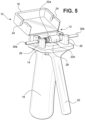
- Fig. 6A shows the hand-held device 10 with the lid 16 closed and the actuator 20 depressed to a first position, where the actuator 20 is moved closer to the handle 18. It will be understood that the lid 16 in Fig. 6A is shown as transparent only for the purpose of showing the inside of the sterilization chamber 12 when the lid 16 is closed. Lid 16 is generally made of an opaque material.
- Fig. 7A shows a top perspective view of the base 14 when the actuator 20 is moved to a first position, as in Fig. 6A .
- holders 26 In the first position, holders 26 have moved from a starting position near the ends of the base 14, to a position closer towards one another to connect connectors 22a, 22b above the light source 28.
- the actuator 20 is further depressed towards the handle 18 to a second position.
- the light source is turned off and the connectors 22a, 22b are moved closer together to engage the O-ring face seals of the spring-plunger system, opening the flow path.
- fluid from one system for example a source of fluid, may flow through the sterilized connection and into a second system.
- Fig. 6B shows the hand-held device 10 with the actuator 20 moved to a second position.
- Fig. 7B shows a top perspective view of the base 14 when the holders 26 have been moved to a second, open flow position. In the second position, holders 26 move from the first position to a second position closer towards one another to open the fluid path between connectors 22a, 22b.
- the actuator 20 may be released, returning it to its starting position.
- the holders 26 are returned to their starting positions near the ends of the base 14, thus closing the fluid pathway and disconnecting the connectors 22a, 22b.
- the lid 16 may be opened to remove the reusable connectors 22a, 22b from the device 10. Both connectors 22a, 22b can be removed from the device. Alternatively, a single connector 22 may be removed and replaced with a new connector attached to a tube in preparation to create a new sterile pathway.
- a hand-held sterilization device including a sterilization chamber defined by a base unit and a lid, an at least one holder within the sterilization chamber, a handle supporting the sterilization chamber, and an actuator configured to cause movement of said at least one holder.
- Aspect 2 The sterilization device of Aspect 1, wherein the lid is attached to the base unit.
- Aspect 3 The sterilization device of any one of Aspects 1 and 2, wherein the lid comprises slots configured to receive tubing when the lid is in a closed position.
- Aspect 4 The sterilization device of any one of Aspects 1-3, comprising a first holder and a second holder.
- Aspect 5 The sterilization device of any one of Aspects 1-4, wherein one of the at least one holder is moveable.
- Aspect 6 The sterilization device of any one of Aspects 4 or 5, wherein the first and second holder are moveable towards each other.
- Aspect 7 The sterilization device of Aspect 6, wherein both the first holder and second holder are moveable to a first position and a second position.
- Aspect 8 The sterilization device of any one of Aspects 1-7, wherein the at least one holder comprises a groove configured to receive a tubing connector.
- Aspect 9 The sterilization device of any one of Aspects 1-8, wherein the actuator is a trigger on the handle.
- Aspect 10 The sterilization device of any one of Aspects 7-9, wherein the actuator is movable to a first position for moving the at least one holder into the holder first position.
- Aspect 11 The sterilization device of any one of Aspects 7-10, wherein the actuator is movable to a second position for moving the at least one holder into a second position.
- Aspect 12 The sterilization device of any one of Aspects 7-8, wherein the actuator is a button on the handle, the button being configured to move the at least one holder into the first position when the button is pressed a first time and to move the at least one holder into the second position when the button is pressed a second time.
- the actuator is a button on the handle, the button being configured to move the at least one holder into the first position when the button is pressed a first time and to move the at least one holder into the second position when the button is pressed a second time.
- Aspect 13 The sterilization device of any one of Aspects 7-8, wherein the actuator is a first and second button on the handle, the first button being configured to move the at least one holder to the first position and the second button being configured to move the at least one holder into the second position.
- the actuator is a first and second button on the handle, the first button being configured to move the at least one holder to the first position and the second button being configured to move the at least one holder into the second position.
- Aspect 14 The sterilization device of any one of Aspects 7-13, wherein sterilization occurs when the at least one holder is in the first position and a fluid pathway is opened when the at least one holder is in the second position.
- a system for providing a sterile fluid pathway connection including a first reusable tube connector configured to receive a first tube and a second reusable tube connector configured to receive a second tube and a hand-held sterilization device.
- the hand-held sterilization device includes a sterilization chamber defined by a base unit and a lid, an at least one holder within the sterilization chamber, wherein said at least one holder is configured to receive one of the first or second reusable connectors, a handle supporting the sterilization chamber, a light source associated with the sterilization chamber, and an actuator configured to move the at least one holder.
- Aspect 16 The system of Aspect 15, wherein the first reusable tube connector is configured to receive the second reusable tube connector to provide a fluid pathway connection.
- Aspect 17 The system of any one of Aspects 15 or 16, wherein the at least one holder comprises a first holder and a second holder, the first holder being configured to receive the first reusable tube connector and the second holder being configured to receive the second reusable tube connector
- Aspect 18 The system of any one of Aspects 15-17, wherein one of the at least one holder is moveable.
- Aspect 19 The system of any one of Aspects 17-18, wherein both the first holder and the second holder are moveable towards each other.
- Aspect 20 The system of any one of Aspects 15-19, wherein the actuator is moveable to a first position to move the at least one holder to a first position.
- Aspect 21 The system of any one of Aspects 15-20, wherein the actuator is moveable to a second position to open a fluid pathway.
- a method for transferring fluid in a sterile manner including attaching an open first end of a tube to a first tube connector wherein said tube includes a second end in flow communication with a source of fluid, attaching an open first end of a second tube to a second tube connector, locating said first and second connectors within a sterilization chamber carried by a handle of a hand-held device, wherein the chamber receives light from a light source associated with the device, temporarily joining said first and second connectors to establish a flow path between said first and second tubes, exposing at least said flow path to a sterilizing light from said light source for a selected period of time, opening the flow path and flowing fluid form said source of fluid though said flow path, and separating said first and second connectors.
- Aspect 23 The method of Aspect 22, further comprising placing the first tube connector into a first holder and the second tube connector into a second holder within the sterilization chamber.
- Aspect 24 The method of any one of Aspects 22-23, further comprising moving an actuator to a first position to establish an air-tight seal between the first connector and second connector.
- Aspect 25 The method of any one of Aspects 22-24, further comprising moving the actuator to a second position to open the flow path.
Landscapes
- Health & Medical Sciences (AREA)
- Epidemiology (AREA)
- Life Sciences & Earth Sciences (AREA)
- Animal Behavior & Ethology (AREA)
- General Health & Medical Sciences (AREA)
- Public Health (AREA)
- Veterinary Medicine (AREA)
- Heart & Thoracic Surgery (AREA)
- Pulmonology (AREA)
- Engineering & Computer Science (AREA)
- Anesthesiology (AREA)
- Biomedical Technology (AREA)
- Hematology (AREA)
- Apparatus For Disinfection Or Sterilisation (AREA)
- Separation Using Semi-Permeable Membranes (AREA)
Abstract
Description
- The present disclosure is directed to a hand-held sterilization device, system, and a method for transferring fluid in a sterile manner. More particularly, the present disclosure is directed to a hand-held sterilization device and system, and a method for creating temporary sterile fluid flow path connections.
- Fluid flow processing systems or assemblies for transferring or dispensing a fluid (liquid) from a source container to one or more receiving containers or receptacles are used in a variety of medical and non-medical applications. In the medical field, in particular, the transfer of fluid must be carried out in a sterile manner, i.e., without exposing the fluids or the open ends of the tubing that carries the fluid to the outside environment. One example of this is the collection of multiple samples from a large volume of a collected biological fluid.
- Currently, sterile connections are typically made by joining the ends of connecting tubing associated with a respective part of a processing system, for instance, by cutting, then melting the tubes together creating a fluid pathway, and then sterilizing the pathway.
- One example of a device that creates a sterile connection is the TSCD-II sterile tubing welder, available from Terumo Medical Corporation. This device uses a heated cutting element to sever and melt the ends of tubing using a heated wafer, which are joined together after the cutting element is removed. The heated wafer creates an aseptic connection. Aspects of this device are disclosed in
U.S. Patent Application Publication No. 2020/0047423 . - One disadvantage of welding devices and the traditional methods of making a sterile connection is that such a connection cannot be easily undone as the tubes are physically and permanently bonded. For example, where a fluid from a single source container must be dispensed to multiple (smaller volume) containers or receptacles, each transfer from the source container would require severing the first connection between the source container to the receiving containers, followed by the (re)establishing a new sterile connection between the source and the next receiving container. This sequence of creating a sterile connection, transferring fluid, severing the connection, and re-establishing a sterile connection with the next receiving container is time-consuming, inefficient, and wasteful.
- Furthermore, currently available tubing welding devices are benchtop devices that require connections to be made wherever the device is located and not necessarily where the transfer of fluid is to occur. Large, benchtop models are not well suited to be moved from place to place.
- Thus, it would be desirable to provide a device which can easily and repeatedly establish a sterile fluid pathway without the successive cutting, heating and physical connecting of plastic tubes. It would also be desirable to provide a portable device that can establish the sterile connection where the fluid transfer is to occur (rather than transport a fluid processing set to a stationary sterile connection device). The device disclosed herein addresses these and other needs.
- There are several aspects of the present subject matter which may be embodied separately or together in the devices and systems described and claimed below. These aspects may be employed alone or in combination with other aspects of the subject matter described herein, and the description of these aspects together is not intended to preclude the use of these aspects separately or the claiming of such aspects separately or in different combinations as set forth in the claims appended hereto.
- In one aspect, a hand-held sterilization device is disclosed. The hand-held sterilization device includes a sterilization chamber defined by a base and a lid and at least one holder within the sterilization chamber. The device includes a handle supporting the sterilization chamber, a light source associated with the sterilization chamber, and an actuator configured to move the at least one holder.
- In another aspect, a system for providing a sterile fluid pathway connection is disclosed. The system includes a first reusable tube connector configured to receive a first tube and a second reusable tube connector configured to receive a second tube and a hand-held sterilization device. The sterilization device of the system includes a sterilization chamber defined by a base and a lid. The chamber includes at least one holder, configured to receive one of the first or second reusable connectors. The hand-held sterilization device includes a handle supporting the sterilization chamber, a light source associated with the sterilization chamber, and an actuator configured to move the at least one holder.
- In yet another aspect, a method for transferring fluid in a sterile manner is disclosed. The method includes attaching an open first end of a tube to a first tube connector wherein the tube includes a second end in flow communication with a source of fluid, and attaching an open first end of a second tube to a second tube connector. The first and second connectors are located within a sterilization chamber carried by a handle of a hand-held device, wherein the chamber receives light from a light source associated with the device. The method further includes temporarily joining the first and second connectors to establish a flow path between the first and second tubes, exposing at least the flow path to a sterilizing light from said light source for a selected period of time, opening the flow path and flowing fluid from said source of fluid through the flow path, and separating the first and second connectors.
-
-
Figure 1 is a perspective view of a sterilization device with a lid in a closed configuration in accordance with the present disclosure; -
Figure 2 is a plan view of a first and second connector; -
Figure 3 is a perspective view of a sterilization device with a lid in an open configuration in accordance with the present disclosure; -
Figure 4 is a flowchart setting forth the steps in the method of creating a sterile connection according to an aspect of the present disclosure; -
Figure 5 is a perspective view of a sterilization device with mounted connectors in accordance with the present disclosure; -
Figure 6A is a perspective view of the sterilization device with the actuator in a first position, in accordance with the present disclosure; -
Figure 6B is a perspective view of the sterilization device with the actuator in a second position, in accordance with the present disclosure; -
Figure 7A is a top perspective view of the sterilization chamber of the sterilization device with the connectors mounted in the holders when the actuator is in a first position ofFig. 6A ; and -
Figure 7B is a top perspective view of the sterilization chamber of the sterilization device with the connectors mounted in the holders when the actuator is in the second position ofFig. 6B . - A more detailed description of the systems and methods in accordance with the present disclosure is set forth below. It should be understood that the description below of specific devices and methods is intended to be exemplary, and not exhaustive of all possible variations or applications. Thus, the scope of the disclosure is not intended to be limiting and should be understood to encompass variations or embodiments that would occur to persons of ordinary skill.
-
Fig. 1 shows a hand-heldsterilization device 10 in accordance with the present disclosure. Thesterilization device 10 includes asterilization chamber 12. Thesterilization chamber 12 is defined by abase 14 and alid 16. Thesterilization device 10 further includes anelongated handle 18 and anactuator 20 configured for one-handed operation by user. The hand-held nature of thesterilization device 10 allows a user to transport thedevice 10 to wherever a sterile connection needs to be made. As opposed to large table-top connection devices, a portable device as disclosed herein provides greater flexibility in choosing a location within a hospital, blood center, or laboratory, for performing the sterile transfer of fluids. -
Sterilization device 10 may be used to sterilize reusable connectors shown and described below. In general, the reusable connectors may be attached to tubing associated with two different parts of a fluid kit, circuit, or system. Using reusable connectors allows a user to make a temporary fluid connection between two tubes without physically welding the tubes together or otherwise making an irreversible permanent connection. Generally, the tubing and fluid kit associated with the respective tubing, including the pre-attached reusable connector, will be sterilized prior to making a connection. -
Fig. 2 shows a first and second reusable connector, 22a and 22b, respectively. The connectors are configured to allow for attachment of open tubing ends to the connectors to create a fluid pathway between the tubing when the connectors are temporarily secured to one another. In one embodiment, thereusable connectors reusable connectors - The outer surfaces of reusable connectors may be, but are not limited to being, made of a transparent material. In one embodiment, the reusable connectors are made of a transparent material that can be penetrated by light from the sterilizing light source. In a more particular embodiment, the material may be transparent to at least UV-C light. In another embodiment, the reusable connectors may be made of a cyclic olefin copolymer (COC). Other transparent materials known in the art may be used without departing from the scope of the disclosure.
- As further seen in
Fig. 2 , the first and secondreusable connectors Reusable connectors connector connector second connectors rings 23 associated with the outside of the secondreusable connector 22b create an air-tight seal within a receivingchamber 21 of the firstreusable connector 22a configured to receive the secondreusable connector 22b. Upon pressing the connectors closer together, spring-activated plungers of both facingconnectors connector -
Fig. 3 shows a hand-heldsterile connection device 10 withlid 16 in an open configuration. In one embodiment,lid 16 may include a top wall orroof 16a andsidewalls Fig. 3 , atleast side walls top wall 16a. One of the side walls e.g., 16e may be permanently attached to an edge ofbase 14 and may be hingedly attached to an edge oftop wall 16a oflid 16, allowinglid 16 to easily flip between an open and closed position without interference from device components (described below) carried bybase 14 and also for convenient mounting ofconnectors sterilization chamber 12. In another embodiment (not shown), thelid 16 may be a completely detachable lid and may be secured in a snap-fit manner tobase 14. Other lids known in the art may be used without departing from the scope of the disclosure. - The footprint of
lid 16 may correspond with the perimeter of thebase 14. For instance, if the perimeter of thebase 14 is a rectangular shape, the footprint oflid 16 will be a corresponding rectangular shape to cover the entirety of thebase 14. -
Lid 16 may includeslots 24 inopposed sidewalls lid 16 is placed in its closed configuration. - As also shown in
Fig. 3 ,sterilization device 10 may include one ormore holders 26 carried bybase 14 configured to receiveconnectors holders 26 initially positioned at opposite ends ofbase 14 withinsterilization chamber 12. Preferably,holders 26 are positioned on either side of alight source 28 inbase 14. - The
holders 26 may be configured to receive a reusable connector(s) 22a, 22b. In one embodiment,holders 26 may include slots such asU-shaped slots 29 for receivingcollars 25, 27 (shown inFig. 2 ) ofconnectors - To establish a sterile flow path, holders 26 (with connectors mounted thereon) are moveable towards each other. Movement of
holders 26 may be initiated byactuator 20 coupled toholders 26. In one embodiment, theactuator 20 may be a trigger. In another embodiment, theactuator 20 may be a button or a set of buttons. For example, by pressing actuator/trigger 20 to a first position,holders 26 may be moved towards one another to a first position, connecting thereusable connectors light source 28. Again, by movingactuator 20 to a second position, themoveable holders 26 may be moved even closer to one another, opening a fluid pathway between thereusable connectors - The
actuator 20 may be attached to thedevice 10 using a pin and hole system. For instance, theactuator 20 may contain a hole in the upper portion. A pin is then inserted through the hole to secure theactuator 20 to thehandle 18. This allows theactuator 20 to rotate about the pin in thehandle 18. Other methods of attaching theactuator 20 to the device may be used without departing from the scope of the disclosure. - In one embodiment, the
actuator 20 is configured to move theholders 26 using a linkage system that will be known to those of skill in the art. For example,actuator 20 may turn a gear which engages two racks configured to moveholders 26 closer together. In another embodiment, theactuator 20 may turn a cam which displaces internal stops to allow for linear springs to move theholders 26 towards one another. In yet another embodiment, theactuator 20 could drive two lead screws or roller screws together to move theconnectors 26 towards one another. - In another embodiment, the
actuator 20 may be a button that sends a signal to a controller configured to move theholders 26. The controller may control motor driven movements within thedevice 10. In one instance, a single button may be used to move theholders 26. The button may be pressed a first time to send a first signal to the controller to move theholders 26 to a first position above thelight source 28. Once theholders 26 are in the first position, thelight source 28 may be activated for a preset amount of time. The button may then be pressed a second time to send a second signal to the controller to move theholders 26 into the second position, opening the fluid pathway. In another example, the button may activate the sterilization process by activating a controller associated with a timer. Once the button is pressed, the controller may move theholders 26 into a first position where they are sterilized for a preset amount of time. After sufficient sterilization, the controller may automatically move theholders 26 to a second position, opening the fluid pathway. The controller may then returnholders 26 to their initial positions after a preset amount of time or by the user pressing the button a second time sending a second signal to the controller. In another instance, a two-button system may be utilized, where a first button may be pressed to move theholders 26 into the first position, and the second button may be pressed to move theholders 26 into the second position. -
Sterilization chamber 12 includes or may be otherwise associated with a light source for providing sterilizing light tosterilization chamber 12. Thelight source 28 may be housed withinbase unit 14 and/or upper region ofhandle 18, such that theconnectors top wall 16a oflid 16 may be coated with a reflective material to provide more uniform irradiation toconnectors inner surface 16a may have a mirror finish. In one embodiment, thelight source 28 is located in the center of thebase 14. In another embodiment, thelight source 28 may span the entire area between theholders 26. - In yet another embodiment, the
light source 28 may be placed anywhere inside thesterilization chamber 12, such that thereusable connectors light source 28. For instance, thelight source 28 could be associated with thelid 16, such that thelight source 28 would irradiate thereusable connectors - The
light source 28 may be, but is not limited to being, an LED light source emitting UV-C light. In an embodiment, thelight source 28 may be a UV-C germicidal bulb. Other sterilizing light sources known in the art may be used without departing from the scope of the disclosure.Device 10 may further include a power supply for poweringlight source 28. Power supply may be housed inhandle 18. In one embodiment, the power supply may be a rechargeable battery. In another embodiment, the power supply may be a cord to be plugged into an electrical socket in a wall. The cord may be long enough to allow for mobile use of thedevice 10. - The hand-held
device 10 may be used to create a temporary sterile connection flow path between a source of fluid and other containers. For instance, it may be desirable to transfer fluid from a source container with a large volume of fluid to many smaller containers. In another aspect, the device may be used to take samples from large biological processes requiring sterile pathways. - Sterilization of connectors using hand-held
device 10 is further shown inFig. 4 , with steps 40-48 setting forth the connection and sterilization steps. Atstep 40 the user will attach a first end of afirst tube 30a to the firstreusable connector 22a and a first end of asecond tube 30b to thesecond connector 22b. Theconnectors reusable connectors reusable connectors reusable connectors reusable connectors device 10. - Once the
reusable connectors step 42 theconnectors sterilization chamber 12 by mounting them into aholder 26, as seen inFig. 5 . In one embodiment, thefirst tubing connector 22a is placed in afirst holder 26 within thesterilization chamber 12 and thesecond connector 22b is placed in asecond holder 26 within thesterilization chamber 12. After theconnectors holders 26, thelid 16 of theseparation chamber 12 may be closed. - At
step 44 theconnectors connectors actuator 20 is moved/pressed to a first position, moving theholders 26 towards one another such thatconnector 22b enters the open end ofconnector 22a. Seal members (O-rings 23) create an air-tight seal betweenconnectors light source 28 is activated. Theactuator 20 may directly activate thelight source 28. Theactuator 20 is kept in the first position for a selected period of time, for example, until the flow path established by theconnectors -
Fig. 6A shows the hand-helddevice 10 with thelid 16 closed and theactuator 20 depressed to a first position, where theactuator 20 is moved closer to thehandle 18. It will be understood that thelid 16 inFig. 6A is shown as transparent only for the purpose of showing the inside of thesterilization chamber 12 when thelid 16 is closed.Lid 16 is generally made of an opaque material. -
Fig. 7A shows a top perspective view of the base 14 when theactuator 20 is moved to a first position, as inFig. 6A . In the first position,holders 26 have moved from a starting position near the ends of thebase 14, to a position closer towards one another to connectconnectors light source 28. - After the flow path is sufficiently irradiated and sterilized, at
step 48 theactuator 20 is further depressed towards thehandle 18 to a second position. In the second position, the light source is turned off and theconnectors -
Fig. 6B shows the hand-helddevice 10 with theactuator 20 moved to a second position.Fig. 7B shows a top perspective view of the base 14 when theholders 26 have been moved to a second, open flow position. In the second position,holders 26 move from the first position to a second position closer towards one another to open the fluid path betweenconnectors - Once the desired transfer of fluid through the sterilized flow path is complete, the
actuator 20 may be released, returning it to its starting position. By releasing theactuator 20, theholders 26 are returned to their starting positions near the ends of thebase 14, thus closing the fluid pathway and disconnecting theconnectors lid 16 may be opened to remove thereusable connectors device 10. Bothconnectors single connector 22 may be removed and replaced with a new connector attached to a tube in preparation to create a new sterile pathway. - Aspects of the present subject matter described above may be beneficial alone or in combination with one or more other Aspects, as described below.
- Aspect 1. A hand-held sterilization device including a sterilization chamber defined by a base unit and a lid, an at least one holder within the sterilization chamber, a handle supporting the sterilization chamber, and an actuator configured to cause movement of said at least one holder.
- Aspect 2. The sterilization device of Aspect 1, wherein the lid is attached to the base unit.
- Aspect 3. The sterilization device of any one of Aspects 1 and 2, wherein the lid comprises slots configured to receive tubing when the lid is in a closed position.
- Aspect 4. The sterilization device of any one of Aspects 1-3, comprising a first holder and a second holder.
- Aspect 5. The sterilization device of any one of Aspects 1-4, wherein one of the at least one holder is moveable.
- Aspect 6. The sterilization device of any one of Aspects 4 or 5, wherein the first and second holder are moveable towards each other.
- Aspect 7. The sterilization device of Aspect 6, wherein both the first holder and second holder are moveable to a first position and a second position.
- Aspect 8. The sterilization device of any one of Aspects 1-7, wherein the at least one holder comprises a groove configured to receive a tubing connector.
- Aspect 9. The sterilization device of any one of Aspects 1-8, wherein the actuator is a trigger on the handle.
-
Aspect 10. The sterilization device of any one of Aspects 7-9, wherein the actuator is movable to a first position for moving the at least one holder into the holder first position. - Aspect 11. The sterilization device of any one of Aspects 7-10, wherein the actuator is movable to a second position for moving the at least one holder into a second position.
-
Aspect 12. The sterilization device of any one of Aspects 7-8, wherein the actuator is a button on the handle, the button being configured to move the at least one holder into the first position when the button is pressed a first time and to move the at least one holder into the second position when the button is pressed a second time. - Aspect 13. The sterilization device of any one of Aspects 7-8, wherein the actuator is a first and second button on the handle, the first button being configured to move the at least one holder to the first position and the second button being configured to move the at least one holder into the second position.
-
Aspect 14. The sterilization device of any one of Aspects 7-13, wherein sterilization occurs when the at least one holder is in the first position and a fluid pathway is opened when the at least one holder is in the second position. - Aspect 15. A system for providing a sterile fluid pathway connection including a first reusable tube connector configured to receive a first tube and a second reusable tube connector configured to receive a second tube and a hand-held sterilization device. The hand-held sterilization device includes a sterilization chamber defined by a base unit and a lid, an at least one holder within the sterilization chamber, wherein said at least one holder is configured to receive one of the first or second reusable connectors, a handle supporting the sterilization chamber, a light source associated with the sterilization chamber, and an actuator configured to move the at least one holder.
-
Aspect 16. The system of Aspect 15, wherein the first reusable tube connector is configured to receive the second reusable tube connector to provide a fluid pathway connection. - Aspect 17. The system of any one of
Aspects 15 or 16, wherein the at least one holder comprises a first holder and a second holder, the first holder being configured to receive the first reusable tube connector and the second holder being configured to receive the second reusable tube connector -
Aspect 18. The system of any one of Aspects 15-17, wherein one of the at least one holder is moveable. - Aspect 19. The system of any one of Aspects 17-18, wherein both the first holder and the second holder are moveable towards each other.
-
Aspect 20. The system of any one of Aspects 15-19, wherein the actuator is moveable to a first position to move the at least one holder to a first position. -
Aspect 21. The system of any one of Aspects 15-20, wherein the actuator is moveable to a second position to open a fluid pathway. -
Aspect 22. A method for transferring fluid in a sterile manner including attaching an open first end of a tube to a first tube connector wherein said tube includes a second end in flow communication with a source of fluid, attaching an open first end of a second tube to a second tube connector, locating said first and second connectors within a sterilization chamber carried by a handle of a hand-held device, wherein the chamber receives light from a light source associated with the device, temporarily joining said first and second connectors to establish a flow path between said first and second tubes, exposing at least said flow path to a sterilizing light from said light source for a selected period of time, opening the flow path and flowing fluid form said source of fluid though said flow path, and separating said first and second connectors. -
Aspect 23. The method ofAspect 22, further comprising placing the first tube connector into a first holder and the second tube connector into a second holder within the sterilization chamber. -
Aspect 24. The method of any one of Aspects 22-23, further comprising moving an actuator to a first position to establish an air-tight seal between the first connector and second connector. -
Aspect 25. The method of any one of Aspects 22-24, further comprising moving the actuator to a second position to open the flow path. - It will be understood that the embodiments and examples described above are illustrative of some of the applications of the principles of the present subject matter. Numerous modifications may be made by those skilled in the art without departing from the spirit and scope of the claimed subject matter, including those combinations of features that are individually disclosed or claimed herein. For these reasons, the scope hereof is not limited to the above description but is as set forth in the following claims, and it is understood that claims may be directed to the features hereof, including as combinations of features that are individually disclosed or claimed herein.
Claims (15)
- A hand-held sterilization device comprising:a sterilization chamber defined by a base unit and a lid;an at least one holder within said sterilization chamber;a handle supporting said sterilization chamber;a light source associated with said sterilization chamber; andan actuator configured to cause movement of said at least one holder.
- The sterilization device of Claim 1, wherein the lid is attached to the base unit and wherein the lid comprises slots configured to receive tubing when the lid is in a closed position.
- The sterilization device of any one of Claims 1-2 comprising a first holder and a second holder, wherein at least one of the first and second holder is moveable.
- The sterilization device of Claim 3, wherein the first and second holder are moveable towards each other to a first position for sterilization and a second position to open a fluid pathway.
- The sterilization device of any one of Claims 1-4, wherein the at least one holder comprises a groove configured to receive a tubing connector.
- The sterilization device of any one of Claims 4-5, wherein the actuator is a trigger on said handle, wherein said trigger is movable to a first position for moving said at least one holder into the holder first position and a second position for moving said at least one holder into a second position.
- The sterilization device of any one of Claims 4-5, wherein said actuator is a button on the handle, said button being configured to move said at least one holder into the first position when said button is pressed a first time and to move said at least one holder into the second position when said button is pressed a second time.
- The sterilization device of any one of Claims 4-5, wherein said actuator comprises a first and second button on the handle, said first button being configured to move the at least one holder to the first position and said second button being configured to move said at least one holder into the second position.
- A system for providing a sterile fluid pathway connection comprising:a first reusable tube connector configured to receive a first tube and a second reusable tube connector configured to receive a second tube; anda hand-held sterilization device, wherein the sterilization device comprises:a sterilization chamber defined by a base unit and a lid;an at least one holder within said sterilization chamber, wherein said at least one holder is configured to receive one of said first or second reusable connectors;a handle supporting said sterilization chamber;a light source associated with said sterilization chamber; andan actuator configured to move said at least one holder.
- The system of Claim 9, wherein the first reusable tube connector is configured to receive the second reusable tube connector to provide a fluid pathway connection.
- The system of any one of Claims 9-10, wherein the at least one holder comprises a first holder and a second holder and at least one of said first holder and second holder is moveable, said first holder being configured to receive the first reusable tube connector and said second holder being configured to receive the second reusable tube connector.
- The system of Claim 11, wherein the actuator is moveable to a first position to move the at least one holder to a first position and to a second position to open a fluid pathway.
- A method for transferring fluid in a sterile manner comprising:attaching an open first end of a tube to a first tube connector wherein said tube includes a second end in flow communication with a source of fluid;attaching an open first end of a second tube to a second tube connector;locating said first and second connectors within a sterilization chamber carried by a handle of a hand-held device, wherein said chamber receives light from a light source associated with said device;temporarily joining said first and second connectors to establish a flow path between said first and second tubes;exposing at least said flow path to a sterilizing light from said light source for a selected period of time;opening the flow path and flowing fluid from said source of fluid through said flow path; andseparating said first and second connectors.
- The method of Claim 13, further comprising placing the first tube connector into a first holder and the second tube connector into a second holder within the sterilization chamber.
- The method of any one of Claim 13-14, further comprising moving an actuator to a first position to establish to establish an air-tight seal between the first connector and second connector and moving said actuator to a second position to open the flow path.
Applications Claiming Priority (1)
| Application Number | Priority Date | Filing Date | Title |
|---|---|---|---|
| US202263319635P | 2022-03-14 | 2022-03-14 |
Publications (4)
| Publication Number | Publication Date |
|---|---|
| EP4245324A2 true EP4245324A2 (en) | 2023-09-20 |
| EP4245324A3 EP4245324A3 (en) | 2023-11-29 |
| EP4245324C0 EP4245324C0 (en) | 2026-05-06 |
| EP4245324B1 EP4245324B1 (en) | 2026-05-06 |
Family
ID=85570111
Family Applications (1)
| Application Number | Title | Priority Date | Filing Date |
|---|---|---|---|
| EP23161102.1A Active EP4245324B1 (en) | 2022-03-14 | 2023-03-10 | Hand-held sterile connection device, system, and method of use |
Country Status (2)
| Country | Link |
|---|---|
| US (1) | US20230285613A1 (en) |
| EP (1) | EP4245324B1 (en) |
Citations (1)
| Publication number | Priority date | Publication date | Assignee | Title |
|---|---|---|---|---|
| US20200047423A1 (en) | 2017-03-24 | 2020-02-13 | Terumo Kabushiki Kaisha | Tube joining device |
Family Cites Families (10)
| Publication number | Priority date | Publication date | Assignee | Title |
|---|---|---|---|---|
| US4412834A (en) * | 1981-06-05 | 1983-11-01 | Baxter Travenol Laboratories | Antimicrobial ultraviolet irradiation of connector for continuous ambulatory peritoneal dialysis |
| US4882496A (en) * | 1988-04-29 | 1989-11-21 | Baxter International Inc. | Apparatus for exchanging and irradiating tubing connections |
| WO2004082741A1 (en) * | 2003-03-20 | 2004-09-30 | Terumo Kabushiki Kaisha | Blood treating set and cell treating set |
| WO2010036617A1 (en) * | 2008-09-23 | 2010-04-01 | Ondine International Holdings Ltd. | Portable photodynamic disinfection light delivery device for catheter disinfection |
| US8105532B2 (en) * | 2008-10-27 | 2012-01-31 | Verilux, Inc. | Mobile disinfectant device and methods |
| US8302248B2 (en) * | 2010-03-08 | 2012-11-06 | Oreck Holdings Llc | Handheld vacuum attachment with ultraviolet light |
| US9056147B2 (en) * | 2012-05-31 | 2015-06-16 | Becton, Dickinson And Company | UV disinfection system for needleless connector |
| US8946653B2 (en) * | 2013-03-14 | 2015-02-03 | Teleflex Medical Incorporated | UV-C catheter hub sterilization and data acquisition system |
| EP3216487B1 (en) * | 2016-03-07 | 2020-05-06 | Fenwal, Inc. | System and method for creating sterile connections using ultraviolet light |
| ES3037643T3 (en) * | 2016-07-11 | 2025-10-03 | Puracath Medical Inc | Point of care ultraviolet disinfection system |
-
2023
- 2023-03-10 US US18/119,971 patent/US20230285613A1/en active Pending
- 2023-03-10 EP EP23161102.1A patent/EP4245324B1/en active Active
Patent Citations (1)
| Publication number | Priority date | Publication date | Assignee | Title |
|---|---|---|---|---|
| US20200047423A1 (en) | 2017-03-24 | 2020-02-13 | Terumo Kabushiki Kaisha | Tube joining device |
Also Published As
| Publication number | Publication date |
|---|---|
| US20230285613A1 (en) | 2023-09-14 |
| EP4245324A3 (en) | 2023-11-29 |
| EP4245324C0 (en) | 2026-05-06 |
| EP4245324B1 (en) | 2026-05-06 |
Similar Documents
| Publication | Publication Date | Title |
|---|---|---|
| EP3216487B1 (en) | System and method for creating sterile connections using ultraviolet light | |
| US12479615B2 (en) | Controlled non-classified filling device and method | |
| CN100488466C (en) | Fluid handling device and its organizer | |
| JP4541614B2 (en) | Processing set and method for processing and processing biological fluids | |
| CA2373899C (en) | Apparatus, systems and methods for processing and treating a biological fluid with light | |
| US4807676A (en) | Fluid transfer workstation | |
| EP2046560B1 (en) | Device for welding plastic tubes | |
| EP0238750A1 (en) | Connection device, especially for peritoneal dialysis | |
| US11731371B2 (en) | Sterile connection of tubing | |
| JPH02504004A (en) | Equipment for replacing and irradiating pipe connections | |
| CN115244164A (en) | a component | |
| US20230285734A1 (en) | Reversible sterile connection system | |
| US20230285613A1 (en) | Hand-held sterile connection device, system, and method of use | |
| US7326897B2 (en) | Clip on tubing welder | |
| US20260137922A1 (en) | Serial Blade Loading For Sterile Connection Device | |
| MXPA00011983A (en) | Direct dual filling device for sealing agents | |
| EP3594655A1 (en) | Electronic sterilisable pipetting device |
Legal Events
| Date | Code | Title | Description |
|---|---|---|---|
| PUAI | Public reference made under article 153(3) epc to a published international application that has entered the european phase |
Free format text: ORIGINAL CODE: 0009012 |
|
| STAA | Information on the status of an ep patent application or granted ep patent |
Free format text: STATUS: THE APPLICATION HAS BEEN PUBLISHED |
|
| AK | Designated contracting states |
Kind code of ref document: A2 Designated state(s): AL AT BE BG CH CY CZ DE DK EE ES FI FR GB GR HR HU IE IS IT LI LT LU LV MC ME MK MT NL NO PL PT RO RS SE SI SK SM TR |
|
| PUAL | Search report despatched |
Free format text: ORIGINAL CODE: 0009013 |
|
| AK | Designated contracting states |
Kind code of ref document: A3 Designated state(s): AL AT BE BG CH CY CZ DE DK EE ES FI FR GB GR HR HU IE IS IT LI LT LU LV MC ME MK MT NL NO PL PT RO RS SE SI SK SM TR |
|
| RIC1 | Information provided on ipc code assigned before grant |
Ipc: A61M 25/00 20060101ALI20231024BHEP Ipc: A61M 39/16 20060101ALI20231024BHEP Ipc: A61L 2/24 20060101ALI20231024BHEP Ipc: A61L 2/10 20060101AFI20231024BHEP |
|
| STAA | Information on the status of an ep patent application or granted ep patent |
Free format text: STATUS: REQUEST FOR EXAMINATION WAS MADE |
|
| 17P | Request for examination filed |
Effective date: 20240529 |
|
| RBV | Designated contracting states (corrected) |
Designated state(s): AL AT BE BG CH CY CZ DE DK EE ES FI FR GB GR HR HU IE IS IT LI LT LU LV MC ME MK MT NL NO PL PT RO RS SE SI SK SM TR |
|
| STAA | Information on the status of an ep patent application or granted ep patent |
Free format text: STATUS: EXAMINATION IS IN PROGRESS |
|
| 17Q | First examination report despatched |
Effective date: 20250130 |
|
| REG | Reference to a national code |
Ref country code: DE Ref legal event code: R079 Free format text: PREVIOUS MAIN CLASS: A61L0002100000 Ipc: A61M0039180000 Ref document number: 602023016507 Country of ref document: DE |
|
| GRAP | Despatch of communication of intention to grant a patent |
Free format text: ORIGINAL CODE: EPIDOSNIGR1 |
|
| STAA | Information on the status of an ep patent application or granted ep patent |
Free format text: STATUS: GRANT OF PATENT IS INTENDED |
|
| RIC1 | Information provided on ipc code assigned before grant |
Ipc: A61M 39/18 20060101AFI20250828BHEP Ipc: A61L 2/10 20060101ALI20250828BHEP Ipc: A61L 2/24 20060101ALI20250828BHEP Ipc: A61M 25/00 20060101ALI20250828BHEP |
|
| INTG | Intention to grant announced |
Effective date: 20250905 |
|
| GRAS | Grant fee paid |
Free format text: ORIGINAL CODE: EPIDOSNIGR3 |
|
| GRAJ | Information related to disapproval of communication of intention to grant by the applicant or resumption of examination proceedings by the epo deleted |
Free format text: ORIGINAL CODE: EPIDOSDIGR1 |
|
| GRAL | Information related to payment of fee for publishing/printing deleted |
Free format text: ORIGINAL CODE: EPIDOSDIGR3 |
|
| STAA | Information on the status of an ep patent application or granted ep patent |
Free format text: STATUS: EXAMINATION IS IN PROGRESS |
|
| GRAP | Despatch of communication of intention to grant a patent |
Free format text: ORIGINAL CODE: EPIDOSNIGR1 |
|
| STAA | Information on the status of an ep patent application or granted ep patent |
Free format text: STATUS: GRANT OF PATENT IS INTENDED |
|
| INTC | Intention to grant announced (deleted) | ||
| INTG | Intention to grant announced |
Effective date: 20260123 |
|
| GRAA | (expected) grant |
Free format text: ORIGINAL CODE: 0009210 |
|
| STAA | Information on the status of an ep patent application or granted ep patent |
Free format text: STATUS: THE PATENT HAS BEEN GRANTED |
|
| AK | Designated contracting states |
Kind code of ref document: B1 Designated state(s): AL AT BE BG CH CY CZ DE DK EE ES FI FR GB GR HR HU IE IS IT LI LT LU LV MC ME MK MT NL NO PL PT RO RS SE SI SK SM TR |
|
| REG | Reference to a national code |
Ref country code: CH Ref legal event code: F10 Free format text: ST27 STATUS EVENT CODE: U-0-0-F10-F00 (AS PROVIDED BY THE NATIONAL OFFICE) Effective date: 20260506 Ref country code: GB Ref legal event code: FG4D |
|
| REG | Reference to a national code |
Ref country code: DE Ref legal event code: R096 Ref document number: 602023016507 Country of ref document: DE |
|
| REG | Reference to a national code |
Ref country code: IE Ref legal event code: FG4D |
|
| U01 | Request for unitary effect filed |
Effective date: 20260527 |
|
| U07 | Unitary effect registered |
Designated state(s): AT BE BG DE DK EE FI FR IT LT LU LV MT NL PT RO SE SI Effective date: 20260608 |