EP4245271B1 - Integrated prosthetic foot with transverse arch - Google Patents
Integrated prosthetic foot with transverse arch Download PDFInfo
- Publication number
- EP4245271B1 EP4245271B1 EP23161957.8A EP23161957A EP4245271B1 EP 4245271 B1 EP4245271 B1 EP 4245271B1 EP 23161957 A EP23161957 A EP 23161957A EP 4245271 B1 EP4245271 B1 EP 4245271B1
- Authority
- EP
- European Patent Office
- Prior art keywords
- plate
- hole
- curve
- arc
- longitudinal
- Prior art date
- Legal status (The legal status is an assumption and is not a legal conclusion. Google has not performed a legal analysis and makes no representation as to the accuracy of the status listed.)
- Active
Links
Images


Classifications
-
- A—HUMAN NECESSITIES
- A61—MEDICAL OR VETERINARY SCIENCE; HYGIENE
- A61F—FILTERS IMPLANTABLE INTO BLOOD VESSELS; PROSTHESES; DEVICES PROVIDING PATENCY TO, OR PREVENTING COLLAPSING OF, TUBULAR STRUCTURES OF THE BODY, e.g. STENTS; ORTHOPAEDIC, NURSING OR CONTRACEPTIVE DEVICES; FOMENTATION; TREATMENT OR PROTECTION OF EYES OR EARS; BANDAGES, DRESSINGS OR ABSORBENT PADS; FIRST-AID KITS
- A61F2/00—Filters implantable into blood vessels; Prostheses, i.e. artificial substitutes or replacements for parts of the body; Appliances for connecting them with the body; Devices providing patency to, or preventing collapsing of, tubular structures of the body, e.g. stents
- A61F2/50—Prostheses not implantable in the body
- A61F2/60—Artificial legs or feet or parts thereof
- A61F2/66—Feet; Ankle joints
-
- A—HUMAN NECESSITIES
- A61—MEDICAL OR VETERINARY SCIENCE; HYGIENE
- A61F—FILTERS IMPLANTABLE INTO BLOOD VESSELS; PROSTHESES; DEVICES PROVIDING PATENCY TO, OR PREVENTING COLLAPSING OF, TUBULAR STRUCTURES OF THE BODY, e.g. STENTS; ORTHOPAEDIC, NURSING OR CONTRACEPTIVE DEVICES; FOMENTATION; TREATMENT OR PROTECTION OF EYES OR EARS; BANDAGES, DRESSINGS OR ABSORBENT PADS; FIRST-AID KITS
- A61F2/00—Filters implantable into blood vessels; Prostheses, i.e. artificial substitutes or replacements for parts of the body; Appliances for connecting them with the body; Devices providing patency to, or preventing collapsing of, tubular structures of the body, e.g. stents
- A61F2/50—Prostheses not implantable in the body
- A61F2/60—Artificial legs or feet or parts thereof
- A61F2/66—Feet; Ankle joints
- A61F2002/6614—Feet
Definitions
- the present invention relates to the technical field of manufacturing of artificial limb, and in particular to an integrated prosthetic foot with transverse arch.
- a prosthetic foot substitutes for human foot and ankle system, and its performance directly affects the overall function of the prosthesis as a main component of the later. Previously, it was mainly designed based on a human foot longitudinal arch feature in order to increase its energy storage capacity and overall elasticity, and reduce the impact on the sole upon landing.
- US20060069450A1 discloses a foot prosthesis having improved rollover and stability.
- the prosthesis includes a first plate and a mounting block having a mounting portion configured to be coupled to a user of the prosthesis, an attachment portion and a gap portion, with the mounting block attached to the first plate at the attachment portion with a gap between the mounting block gap portion and the first plate.
- a resilient element positioned at least partially within the gap, the resilient element configured generally to dissipate stress in the first plate and control deflection between the first plate and the mounting block.
- the mounting block may be substantially rigid with the area of the first plate attached to the mounting block becoming substantially rigid while the remainder of the first plate is at least partially flexible.
- the resilient element may be interchangeable to adjust performance of the prosthesis.
- CN113332010A discloses a separated prosthetic foot with a transverse arch, which belongs to the technical field of manufacturing of artificial limbs.
- the characteristics of the transverse arch of the human foot are combined into the previous transverse-straight carbon fiber foot design to improve the stiffness of the prosthetic foot and reduce the weight of the prosthetic foot.
- a forefoot part employs a separated curved plate design, and two simple curved plates with different curvatures are used for simulating a complex curved surface of the transverse arch of the human, such that the manufacturing cost is reduced, and the various parts of the sole are non-uniform in stiffness distribution: the outer side of the foot is a single-layer forefoot plate with a smaller curvature and minor stiffness; and the inner side of the foot is a double-layer stacked forefoot plate, and the lower layer plate has a large radius in curvature and stiffness.
- CN112206084A discloses a prosthetic foot.
- the prosthetic foot has a gradient rigidity change of a three-dimensional curvature feature of an arch of a human body and belongs to a technical field of artificial prosthesis manufacturing.
- the prosthetic foot includes a forefoot carbon fiber curved plate, a heel carbon fiber curved plate and a connection assembly, a three-dimensional curved surface shape of the prosthetic foot is designed in combination with the three-dimensional curvature features of a longitudinal arch and a transverse arch of a human foot, and the prosthetic foot with gradient rigidity distribution is provided.
- weight of the prosthetic foot is reduced while overall rigidity of the prosthetic foot is improved, so as to achieve better supporting and propelling effects and lighter and more comfortable use experience; and on the other hand, the gradient rigidity change, with larger rigidity of a rear part, smaller rigidity of a front part, larger rigidity of inner partial toes and smaller rigidity of outer partial toes, of the prosthetic foot dynamically meets different requirements of different road conditions and different walking stages on the rigidity of different parts of the prosthetic foot, such that the response of the prosthetic foot to movement is more intelligent, timely and reliable.
- An objective of the present invention is to provide an integrated prosthetic foot combining a human foot transverse arch feature and a changing rule of a plantar pressure in a gait cycle aiming at the shortcomings of an existing carbon fiber prosthetic foot.
- a three-dimensional curvature feature of a human foot arch is combined into design of a transversely flat carbon fiber prosthetic foot, thereby satisfying rigidity requirements from the prosthetic foot, greatly reducing a weight of the prosthetic foot, and providing higher wearing comfort for a patient;
- the prosthetic foot adopts integrated curved plate design, and a forefoot and a heel are designed into a curved plate having functions of the forefoot and the heel, and has features of a longitudinal arch and a transverse arch from the heel to the forefoot, thereby greatly simplifying disassembly and assembly processes and reducing manufacturing cost.
- An integrated prosthetic foot with transverse arch of the present invention includes a sole curved plate A, a adapting piece B, a first bolt group 1, a second bolt group 2, a third bolt group 3 and a fourth bolt group 4, wherein the sole curved plate A is a carbon fiber composite plate, and includes a rear plate 5a, a rear transition plate 5b, a middle arc plate 5c, a middle transition plate 5d and a front flat plate 5e, the rear plate 5a, the rear transition plate 5b and the middle arc plate 5c, the middle transition plate 5d and the front flat plate 5e are smoothly connected into a whole unit in sequence from back to front.
- the adapting piece B is made of aluminum alloy, and includes a square frustum 6a, a platform 6b and a main body 6c, the square frustum 6a is fixedly connected to a rear portion of the main body 6c by means of the platform 6b; the rear flat plate 5a and the front flat plate 5e are broken lines, the broken lines are formed by connecting two straight lines with a height difference of 2mm by means of arc transition; the rear transition plate 5b and the middle transition plate 5d each smoothly transition from an upward convex arc shape to a straight shape, with an arc radius of 20mm-25mm, a central angle of 80°-85°, and a curvature going from large to small; and the middle arc plate 5c has a transverse curve designed with reference to a human foot transverse arch curve, and a front end and a back end are connected by means of a smooth arc transition.
- the sole curved plate A is wholly defined by a longitudinal sole curve C, an outer longitudinal curve D and an inner longitudinal curve E in a front and back direction, the longitudinal sole curve C includes a first longitudinal curve 5j, a second longitudinal curve 5k and a third longitudinal line 5l;
- the first longitudinal 5j is a downward concave arc with an arc radius of 60mm-70mm and a central angle of 43°-45°
- the second longitudinal curve 5k is an upward concave arc with an arc radius of 50mm-60mm and a central angle of 74°-76°
- the first longitudinal curve 5j and the second longitudinal curve 5k are connected in sequence and smoothly in a tangential manner from back to front;
- the third longitudinal curve 5l is a downward concave arc with an arc radius of 100mm-110mm and a central angle of 40°-42°, and the second longitudinal curve 5k and the third longitudinal curve 5l are connected in sequence and smoothly in a tangential manner from back to front.
- Shapes of the outer longitudinal curve D and the inner longitudinal curve E are drawn according to a basic shape of a human longitudinal arch and have a greater inner curvature and a smaller outer curvature.
- the adapting piece B and the sole curved plate A are arranged vertically, and are fixedly connected by the first bolt group 1, the second bolt group 2, the third bolt group 3 and the fourth bolt group 4.
- a bottom surface of the main body 6c of the adapting piece B has the same size as arc surfaces of the rear transition plate 5b, the middle arc plate 5c and the middle transition plate 5d of the sole curved plate A.
- a middle potion of the main body 6c is provided with three elliptical holes of a weight-reducing hole group 6g, a short axis of an ellipse is 2mm-8mm, and a long axis of the ellipse is 9mm-30mm.
- the bottom surface of the main body 6c is a curved surface designed per the human foot transverse arch curve, and fits an upper surface of the sole curved plate A.
- the rear transition plate 5b of the sole curved plate A is provided with a first rear hole 5i
- the middle arc plate 5c is provided with a first middle hole 5g and a second middle hole 5h
- the middle transition plate 5d is provided with a first front hole 5f
- a bottom of the main body 6c of the adapting piece B is provided with a second front hole 6d, a third middle hole 6e, a fourth middle hole 6f and a second rear hole 6h.
- the second rear hole 6h, the third middle hole 6e, the fourth middle hole 6f and the second front hole 6d in sequence correspond vertically to the first rear hole 5i, the second middle hole 5h, the first middle hole 5g and the first front hole 5f respectively.
- a plantar pressure center starts at the heel touching ground, gradually moves forward from the heel to outside of the forefoot, and then moves to inside of the forefoot during the human foot touches the ground completely.
- Plantar pressures on a human foot are not uniform in different stages, so stiffness required for different portions of the sole to bear the pressures is also different.
- sole longitudinal arch curves of inside and outside of the prosthetic foot of the present invention are different, that is, the sole has a smaller curvature on the outer longitudinal curve D, and a larger deformation amount when being stressed, such that impact force generated when the sole touches the ground is absorbed while the sole may conveniently adapt to various road conditions, buffering and energy storing are achieved, and comfort of a wearer during walking is improved; and the sole has a larger curvature on the inner longitudinal curve E, so as to provide a greater rigidity for the prosthetic foot and a better support and propulsion during walking.
- a square frustum 6b. a platform; 6c. a main body; 6d. a second front hole; 6e. a third middle hole; 6f. a fourth middle hole; 6g. a weight-reducing hole group; 6h. a second rear hole.
- the present invention includes a sole curved plate A, a adapting piece B, a first bolt group 1, a second bolt group 2, a third bolt group 3 and a fourth bolt group 4.
- a bottom surface of a main body 6c of the adapting piece B has the same size as arc surfaces of a rear transition plate 5b, a middle arc plate 5c and a middle transition plate 5d of the sole curved plate A.
- a second rear hole 6h, a third middle hole 6e, a fourth middle hole 6f and a second front hole 6d in sequence correspond vertically to a first rear hole 5i, a second middle hole 5h, a first middle hole 5g and a first front hole 5f respectively.
- the adapting piece B and the sole curved plate A are arranged vertically, and are fixedly connected by the first bolt group 1, the second bolt group 2, the third bolt group 3 and the fourth bolt group 4.
- the sole curved plate A is a carbon fiber composite plate, and includes a rear plate 5a, the rear transition plate 5b, the middle arc plate 5c, the middle transition plate 5d and a front flat plate 5e, the rear plate 5a, the rear transition plate 5b and the middle arc plate 5c, the middle transition plate 5d and the front flat plate 5e are smoothly connected into a whole unit in sequence from back to front.
- the rear flat plate 5a and the front flat plate 5e are broken lines, the broken lines are formed by connecting two straight lines with a height difference of 2mm by means of arc transition.
- the rear transition plate 5b and the middle transition plate 5d each smoothly transition from an upward convex arc shape to a straight shape, with an arc radius of 20mm-25mm, a central angle of 80°-85°, and a curvature going from large to small.
- the middle arc plate 5c has a transverse curve designed with reference to a human foot transverse arch curve, and a front end and a back end are connected by means of a smooth arc transition.
- the sole curved plate A is wholly defined by a longitudinal sole curve C, an outer longitudinal curve D and an inner longitudinal curve E in a front and back direction
- the longitudinal sole curve C includes a first longitudinal curve 5j, a second longitudinal curve 5k and a third longitudinal curve 5l.
- the first longitudinal 5j is a downward concave arc having an arc radius of 60mm-70mm and a central angle of 43°-45°
- the second longitudinal curve 5k is an upward concave arc having an arc radius of 50mm-60mm and a central angle of 74°-76°
- the first longitudinal curve 5j and the second longitudinal curve 5k are connected in sequence and smoothly in a tangential manner from back to front.
- the third longitudinal curve 5l is a downward concave arc having an arc radius of 100mm-110mm and a central angle of 40°-42°, and the second longitudinal curve 5k and the third longitudinal curve 5l are connected in sequence and smoothly in a tangential manner from back to front.
- Shapes of the outer longitudinal curve D and the inner longitudinal curve E are drawn according to a basic shape of a human longitudinal arch and have a greater inner curvature and a smaller outer curvature.
- the adapting piece B is made of aluminum alloy, and includes a square frustum 6a, a platform 6b and a main body 6c, the square frustum 6a is fixedly connected to a rear portion of the main body 6c by means of the platform 6b.
- a bottom of the main body 6c of the adapting piece B is provided with a second front hole 6d, a third middle hole 6e, a fourth middle hole 6f and a second rear hole 6h.
- a middle potion of the main body 6c is provided with three elliptical holes of a weight-reducing hole group 6g, a short axis of an ellipse is 2mm-8mm, and a long axis of the ellipse is 9mm-30mm.
- the bottom surface of the main body 6c is a curved surface designed per the human foot transverse arch curve, and fits an upper surface of the sole curved plate A.
Landscapes
- Health & Medical Sciences (AREA)
- Transplantation (AREA)
- Biomedical Technology (AREA)
- Cardiology (AREA)
- Oral & Maxillofacial Surgery (AREA)
- Engineering & Computer Science (AREA)
- Orthopedic Medicine & Surgery (AREA)
- Heart & Thoracic Surgery (AREA)
- Vascular Medicine (AREA)
- Life Sciences & Earth Sciences (AREA)
- Animal Behavior & Ethology (AREA)
- General Health & Medical Sciences (AREA)
- Public Health (AREA)
- Veterinary Medicine (AREA)
- Prostheses (AREA)
Description
- The present invention relates to the technical field of manufacturing of artificial limb, and in particular to an integrated prosthetic foot with transverse arch.
- The disabled people totaled 85.01 million in China by the end of 2010, including 24.72 million physically disabled ones. Amputation not only brings burdens to patients and their families, but also greatly affects their psychological state and interpersonal relationship. Prostheses can be used to replace limbs to a certain extent in terms of motor function, and are the best means to help amputees improve their mobility and fit into social life at present. A prosthetic foot substitutes for human foot and ankle system, and its performance directly affects the overall function of the prosthesis as a main component of the later. Previously, it was mainly designed based on a human foot longitudinal arch feature in order to increase its energy storage capacity and overall elasticity, and reduce the impact on the sole upon landing. In the prior art, carbon fiber composite materials are usually used to manufacture the prosthetic foot, and make, on accounts of their directionality, the carbon fiber prosthetic foot have higher stiffness in the direction of longitudinal arc, which is contrary in the direction of transverse arch. And, a transversely flat and even-thick prosthetic foot has poor dynamic response to different gaits during support, causing impact force to be transmitted to stumps, and further affecting comfort and stability of the prosthesis. Relevant researches show that a human foot transverse arch feature can effectively improve the overall stiffness of the sole, and play a vital role in different motion states. To this end, it is necessary to design a new prosthetic foot having a transverse arch combining a curvature change feature of the human foot transverse arc, which can improve the overall stiffness of the prosthetic foot, effectively reduce the weight of the sole, and effectively improve the stability and comfort of the prosthesis under different road conditions.
-
US20060069450A1 discloses a foot prosthesis having improved rollover and stability. The prosthesis includes a first plate and a mounting block having a mounting portion configured to be coupled to a user of the prosthesis, an attachment portion and a gap portion, with the mounting block attached to the first plate at the attachment portion with a gap between the mounting block gap portion and the first plate. Also included is a resilient element positioned at least partially within the gap, the resilient element configured generally to dissipate stress in the first plate and control deflection between the first plate and the mounting block. The mounting block may be substantially rigid with the area of the first plate attached to the mounting block becoming substantially rigid while the remainder of the first plate is at least partially flexible. The resilient element may be interchangeable to adjust performance of the prosthesis. -
CN113332010A discloses a separated prosthetic foot with a transverse arch, which belongs to the technical field of manufacturing of artificial limbs. The characteristics of the transverse arch of the human foot are combined into the previous transverse-straight carbon fiber foot design to improve the stiffness of the prosthetic foot and reduce the weight of the prosthetic foot. A forefoot part employs a separated curved plate design, and two simple curved plates with different curvatures are used for simulating a complex curved surface of the transverse arch of the human, such that the manufacturing cost is reduced, and the various parts of the sole are non-uniform in stiffness distribution: the outer side of the foot is a single-layer forefoot plate with a smaller curvature and minor stiffness; and the inner side of the foot is a double-layer stacked forefoot plate, and the lower layer plate has a large radius in curvature and stiffness. -
CN112206084A discloses a prosthetic foot. The prosthetic foot has a gradient rigidity change of a three-dimensional curvature feature of an arch of a human body and belongs to a technical field of artificial prosthesis manufacturing. The prosthetic foot includes a forefoot carbon fiber curved plate, a heel carbon fiber curved plate and a connection assembly, a three-dimensional curved surface shape of the prosthetic foot is designed in combination with the three-dimensional curvature features of a longitudinal arch and a transverse arch of a human foot, and the prosthetic foot with gradient rigidity distribution is provided. Compared with a carbon fiberfootstraight in a transverse direction, on one hand, weight of the prosthetic foot is reduced while overall rigidity of the prosthetic foot is improved, so as to achieve better supporting and propelling effects and lighter and more comfortable use experience; and on the other hand, the gradient rigidity change, with larger rigidity of a rear part, smaller rigidity of a front part, larger rigidity of inner partial toes and smaller rigidity of outer partial toes, of the prosthetic foot dynamically meets different requirements of different road conditions and different walking stages on the rigidity of different parts of the prosthetic foot, such that the response of the prosthetic foot to movement is more intelligent, timely and reliable. - An objective of the present invention is to provide an integrated prosthetic foot combining a human foot transverse arch feature and a changing rule of a plantar pressure in a gait cycle aiming at the shortcomings of an existing carbon fiber prosthetic foot. A three-dimensional curvature feature of a human foot arch is combined into design of a transversely flat carbon fiber prosthetic foot, thereby satisfying rigidity requirements from the prosthetic foot, greatly reducing a weight of the prosthetic foot, and providing higher wearing comfort for a patient; the prosthetic foot adopts integrated curved plate design, and a forefoot and a heel are designed into a curved plate having functions of the forefoot and the heel, and has features of a longitudinal arch and a transverse arch from the heel to the forefoot, thereby greatly simplifying disassembly and assembly processes and reducing manufacturing cost.
- An integrated prosthetic foot with transverse arch of the present invention includes a sole curved plate A, a adapting piece B, a
first bolt group 1, asecond bolt group 2, athird bolt group 3 and afourth bolt group 4, wherein the sole curved plate A is a carbon fiber composite plate, and includes arear plate 5a, arear transition plate 5b, amiddle arc plate 5c, amiddle transition plate 5d and a frontflat plate 5e, therear plate 5a, therear transition plate 5b and themiddle arc plate 5c, themiddle transition plate 5d and the frontflat plate 5e are smoothly connected into a whole unit in sequence from back to front. - The adapting piece B is made of aluminum alloy, and includes a
square frustum 6a, aplatform 6b and amain body 6c, thesquare frustum 6a is fixedly connected to a rear portion of themain body 6c by means of theplatform 6b; the rearflat plate 5a and the frontflat plate 5e are broken lines, the broken lines are formed by connecting two straight lines with a height difference of 2mm by means of arc transition; therear transition plate 5b and themiddle transition plate 5d each smoothly transition from an upward convex arc shape to a straight shape, with an arc radius of 20mm-25mm, a central angle of 80°-85°, and a curvature going from large to small; and themiddle arc plate 5c has a transverse curve designed with reference to a human foot transverse arch curve, and a front end and a back end are connected by means of a smooth arc transition. - The sole curved plate A is wholly defined by a longitudinal sole curve C, an outer longitudinal curve D and an inner longitudinal curve E in a front and back direction, the longitudinal sole curve C includes a first
longitudinal curve 5j, a secondlongitudinal curve 5k and a third longitudinal line 5l; the first longitudinal 5j is a downward concave arc with an arc radius of 60mm-70mm and a central angle of 43°-45°, the secondlongitudinal curve 5k is an upward concave arc with an arc radius of 50mm-60mm and a central angle of 74°-76°, and the firstlongitudinal curve 5j and the secondlongitudinal curve 5k are connected in sequence and smoothly in a tangential manner from back to front; and the third longitudinal curve 5l is a downward concave arc with an arc radius of 100mm-110mm and a central angle of 40°-42°, and the secondlongitudinal curve 5k and the third longitudinal curve 5l are connected in sequence and smoothly in a tangential manner from back to front. - Shapes of the outer longitudinal curve D and the inner longitudinal curve E are drawn according to a basic shape of a human longitudinal arch and have a greater inner curvature and a smaller outer curvature.
- A mathematical expression of the outer longitudinal curve D is: y = -0.0015x3+0.3313x2-3.5641x.
- A mathematical expression of the inner longitudinal curve E is: y = -0.0025x3+0.5492x2-9.6027x.
- The adapting piece B and the sole curved plate A are arranged vertically, and are fixedly connected by the
first bolt group 1, thesecond bolt group 2, thethird bolt group 3 and thefourth bolt group 4. - A bottom surface of the
main body 6c of the adapting piece B has the same size as arc surfaces of therear transition plate 5b, themiddle arc plate 5c and themiddle transition plate 5d of the sole curved plate A. - A middle potion of the
main body 6c is provided with three elliptical holes of a weight-reducinghole group 6g, a short axis of an ellipse is 2mm-8mm, and a long axis of the ellipse is 9mm-30mm. - The bottom surface of the
main body 6c is a curved surface designed per the human foot transverse arch curve, and fits an upper surface of the sole curved plate A. - The
rear transition plate 5b of the sole curved plate A is provided with a first rear hole 5i, themiddle arc plate 5c is provided with afirst middle hole 5g and asecond middle hole 5h, and themiddle transition plate 5d is provided with a firstfront hole 5f; and a bottom of themain body 6c of the adapting piece B is provided with a secondfront hole 6d, athird middle hole 6e, afourth middle hole 6f and a secondrear hole 6h. - The second
rear hole 6h, thethird middle hole 6e, thefourth middle hole 6f and the secondfront hole 6d in sequence correspond vertically to the first rear hole 5i, thesecond middle hole 5h, thefirst middle hole 5g and the firstfront hole 5f respectively. - In a complete gait cycle, a plantar pressure center starts at the heel touching ground, gradually moves forward from the heel to outside of the forefoot, and then moves to inside of the forefoot during the human foot touches the ground completely. Plantar pressures on a human foot are not uniform in different stages, so stiffness required for different portions of the sole to bear the pressures is also different. Therefore, sole longitudinal arch curves of inside and outside of the prosthetic foot of the present invention are different, that is, the sole has a smaller curvature on the outer longitudinal curve D, and a larger deformation amount when being stressed, such that impact force generated when the sole touches the ground is absorbed while the sole may conveniently adapt to various road conditions, buffering and energy storing are achieved, and comfort of a wearer during walking is improved; and the sole has a larger curvature on the inner longitudinal curve E, so as to provide a greater rigidity for the prosthetic foot and a better support and propulsion during walking. In the gait cycle, when the sole touches the ground, a center of gravity of a human body first falls on the back
flat plate 5a of the sole curved plate A, and then gradually shifts from the backflat plate 5a to the outer longitudinal curve D of the frontflat plate 5e; and then the impact force is transferred from the outer longitudinal curve D of thefront plate 5e to the inner longitudinal curve E of thefront plate 5e. - The present invention has the following beneficial effects:
- 1. The present invention combines the human transverse arch feature and the human longitudinal arch feature into the design of the prosthetic foot, and improves the traditional transversely flat carbon fiber plate into the transverse curved carbon fiber plate having a transverse arch feature, which may provide the rigidity required by the patient during walking under various road conditions and effectively reduce the weight of the prosthetic foot; the sole adopts integrated curved plate design, a simple carbon fiber curved plate is used as the main body of the prosthetic foot, and a forefoot and a heel of a conventional prosthetic foot are combined to form one curved plate, such that the prosthetic foot has the functions of the forefoot and the heel, thereby greatly simplifying disassembly and assembly difficulty and reducing the manufacturing cost and difficulty.
- 2. The sole of the prosthetic foot is designed with reference to the change rule of the plantar pressure center, rigidity distribution over various portions is made nonuniform by making the curvature of the inner and outer longitudinal curves of the sole different, such that the inner curvature of the sole is larger and the rigidity is larger; the outer curvature of the sole is smaller, and the rigidity is smaller; and the design of different curvature causes the prosthetic foot to satisfy the requirements of stiffness and comfort at different walking stages in the gait cycle.
-
-
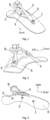
Fig. 1 shows a first axonometric view (in a front right direction) of an integrated transverse arch prosthetic foot; -
Fig. 2 shows a second axonometric view (in a rear right direction) of the integrated transverse arch prosthetic foot; -
Fig. 3 shows a third axonometric view (in a bottom right direction) of the integrated transverse arch prosthetic foot; -
Fig. 4 shows an explosive view (in a front right direction) of the integrated transverse arch prosthetic foot; -
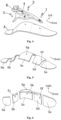
Fig. 5 shows a first axonometric view (in a front right direction) of segmented cross sections of a sole curved plate A; -
Fig. 6 shows a second axonometric view (in a bottom right direction) of segmented cross sections of the sole curved plate A; -
Fig. 7 shows a right side view of a longitudinal sole curve C; -
Fig. 8 shows an axonometric view (in a front right direction) of an outer longitudinal curve D and an inner longitudinal curve E; -
Fig. 9 shows a first axonometric view (in a front right direction) of a adapting piece B; and -
Fig. 10 shows a second axonometric view (in a rear right direction) of the adapting piece B. - In the figures: A. a sole curved plate; B. a adapting piece; C. a longitudinal sole curve; D. an outer longitudinal curve; E. an inner longitudinal curve; 1. a first bolt group; 2. a second bolt group; 3. a third bolt group; 4. a fourth bolt group; 5a. a rear flat plate; 5b. a rear transition plate; 5c. a middle arc plate; 5d. a middle transition plate; 5e. a front flat plate; 5f. a first front hole; 5g. a second middle hole; 5h. a first middle hole; 5i. a first rear hole; 5j. a first longitudinal curve; 5k. a second longitudinal curve; 5l. a third longitudinal curve; 6a. a square frustum; 6b. a platform; 6c. a main body; 6d. a second front hole; 6e. a third middle hole; 6f. a fourth middle hole; 6g. a weight-reducing hole group; 6h. a second rear hole.
- The present invention will be described below with reference to accompanying drawings.
- As shown in
Figs. 1-4 , the present invention includes a sole curved plate A, a adapting piece B, afirst bolt group 1, asecond bolt group 2, athird bolt group 3 and afourth bolt group 4. A bottom surface of amain body 6c of the adapting piece B has the same size as arc surfaces of arear transition plate 5b, amiddle arc plate 5c and amiddle transition plate 5d of the sole curved plate A. A secondrear hole 6h, a thirdmiddle hole 6e, a fourthmiddle hole 6f and a secondfront hole 6d in sequence correspond vertically to a first rear hole 5i, a secondmiddle hole 5h, a firstmiddle hole 5g and a firstfront hole 5f respectively. The adapting piece B and the sole curved plate A are arranged vertically, and are fixedly connected by thefirst bolt group 1, thesecond bolt group 2, thethird bolt group 3 and thefourth bolt group 4. - As shown in
Figs. 5-6 , the sole curved plate A is a carbon fiber composite plate, and includes arear plate 5a, therear transition plate 5b, themiddle arc plate 5c, themiddle transition plate 5d and a frontflat plate 5e, therear plate 5a, therear transition plate 5b and themiddle arc plate 5c, themiddle transition plate 5d and the frontflat plate 5e are smoothly connected into a whole unit in sequence from back to front. The rearflat plate 5a and the frontflat plate 5e are broken lines, the broken lines are formed by connecting two straight lines with a height difference of 2mm by means of arc transition. Therear transition plate 5b and themiddle transition plate 5d each smoothly transition from an upward convex arc shape to a straight shape, with an arc radius of 20mm-25mm, a central angle of 80°-85°, and a curvature going from large to small. And themiddle arc plate 5c has a transverse curve designed with reference to a human foot transverse arch curve, and a front end and a back end are connected by means of a smooth arc transition. - As shown in
Figs. 7-8 , the sole curved plate A is wholly defined by a longitudinal sole curve C, an outer longitudinal curve D and an inner longitudinal curve E in a front and back direction, the longitudinal sole curve C includes a firstlongitudinal curve 5j, a secondlongitudinal curve 5k and a third longitudinal curve 5l. The first longitudinal 5j is a downward concave arc having an arc radius of 60mm-70mm and a central angle of 43°-45°, the secondlongitudinal curve 5k is an upward concave arc having an arc radius of 50mm-60mm and a central angle of 74°-76°, and the firstlongitudinal curve 5j and the secondlongitudinal curve 5k are connected in sequence and smoothly in a tangential manner from back to front. And the third longitudinal curve 5l is a downward concave arc having an arc radius of 100mm-110mm and a central angle of 40°-42°, and the secondlongitudinal curve 5k and the third longitudinal curve 5l are connected in sequence and smoothly in a tangential manner from back to front. - Shapes of the outer longitudinal curve D and the inner longitudinal curve E are drawn according to a basic shape of a human longitudinal arch and have a greater inner curvature and a smaller outer curvature.
- A mathematical expression of the outer longitudinal curve D is: y = -0.0015x3+0.3313x2-3.5641x.
- A mathematical expression of the inner longitudinal curve E is: y = -0.0025x3+0.5492x2-9.6027x.
- As shown in
Figs. 9-10 , the adapting piece B is made of aluminum alloy, and includes asquare frustum 6a, aplatform 6b and amain body 6c, thesquare frustum 6a is fixedly connected to a rear portion of themain body 6c by means of theplatform 6b. A bottom of themain body 6c of the adapting piece B is provided with a secondfront hole 6d, a thirdmiddle hole 6e, a fourthmiddle hole 6f and a secondrear hole 6h. A middle potion of themain body 6c is provided with three elliptical holes of a weight-reducinghole group 6g, a short axis of an ellipse is 2mm-8mm, and a long axis of the ellipse is 9mm-30mm. And the bottom surface of themain body 6c is a curved surface designed per the human foot transverse arch curve, and fits an upper surface of the sole curved plate A.
Claims (3)
- An integrated prosthetic foot with transverse arch, comprising a sole curved plate (A), an adapting piece (B), a first bolt group (1), a second bolt group (2), a third bolt group (3) and a fourth bolt group (4), wherein the sole curved plate (A) comprises a rear flat plate (5a), a rear transition plate (5b), a middle arc plate (5c), a middle transition plate (5d) and a front flat plate (5e), the rear flat plate (5a), the rear transition plate (5b), the middle arc plate (5c), the middle transition plate (5d) and the front flat plate (5e) are smoothly connected into a whole unit in sequence from back to front; the adapting piece (B) comprises a square frustum (6a), a platform (6b) and a main body (6c), the square frustum (6a) is fixedly connected to a rear portion of the main body (6c) by means of the platform (6b); the rear flat plate (5a) and the front flat plate (5e) are broken lines, the broken lines are formed by connecting two straight lines with a height difference of 2mm by means of arc transition; the rear transition plate (5b) and the middle transition plate (5d) each smoothly transition from an upward convex arc shape to a straight shape, with an arc radius of 20mm-25mm, a central angle of 80°-85°, and a curvature going from large to small; the middle arc plate (5c) has a transverse curve designed with reference to a human foot transverse arch curve, and a front end and a back end are connected by means of a smooth arc transition; the sole curved plate (A) is wholly defined by a longitudinal sole curve (C), an outer longitudinal curve (D) and an inner longitudinal curve (E) in a front and back direction, the longitudinal sole curve (C) comprises a first longitudinal curve (5j), a second longitudinal curve (5k) and a third longitudinal curve (5l); the first longitudinal curve (5j) is a downward concave arc with an arc radius of 60mm-70mm and a central angle of 43°-45°, the second longitudinal curve (5k) is an upward concave arc with an arc radius of 50mm-60mm and a central angle of 74°-76°, and the first longitudinal curve (5j) and the second longitudinal curve (5k) are connected in sequence and smoothly in a tangential manner from back to front; the third longitudinal curve (5l) is a downward concave arc with an arc radius of 100mm-110mm and a central angle of 40°-42°, and the second longitudinal curve (5k) and the third longitudinal curve (5l) are connected in sequence and smoothly in a tangential manner from back to front; shapes of the outer longitudinal curve (D) and the inner longitudinal curve (E) are drawn according to a basic shape of a human longitudinal arch and have a greater inner curvature and a smaller outer curvature;a mathematical expression of the outer longitudinal curve (D) is: y = -0.0015x3+0.3313x2-3.5641x;a mathematical expression of the inner longitudinal curve (E) is: y = -0.0025x3+0.5492x2-9.6027x; andthe adapting piece (B) and the sole curved plate (A) are arranged vertically, and are fixedly connected by the first bolt group (1), the second bolt group (2), the third bolt group (3) and the fourth bolt group (4); a bottom surface of the main body (6c) of the adapting piece (B) has the same size as arc surfaces of the rear transition plate (5b), the middle arc plate (5c) and the middle transition plate (5d) of the sole curved plate (A); a middle potion of the main body (6c) is provided with three elliptical holes of a weight-reducing hole group (6g), a short axis of an ellipse is 2mm-8mm, and a long axis of the ellipse is 9mm-30mm; and the bottom surface of the main body (6c) is a curved surface designed per the human foot transverse arch curve, and fits an upper surface of the sole curved plate (A).
- The integrated prosthetic foot with transverse arch as claimed in claim 1, wherein the rear transition plate (5b) of the sole curved plate (A) is provided with a first rear hole (5i), the middle arc plate (5c) is provided with a first middle hole (5g) and a second middle hole (5h), and the middle transition plate (5d) is provided with a first front hole (5f); a bottom of the main body (6c) of the adapting piece (B) is provided with a second front hole (6d), a third middle hole (6e), a fourth middle hole (6f) and a second rear hole (6h); and the second rear hole (6h), the third middle hole (6e), the fourth middle hole (6f) and the second front hole (6d) in sequence correspond vertically to the first rear hole (5i), the second middle hole (5h), the first middle hole (5g) and the first front hole (5f) respectively.
- The integrated prosthetic foot with transverse arch as claimed in claim 1, wherein the sole curved plate (A) is a carbon fiber composite plate, and the adapting piece (B) is made of aluminum alloy.
Applications Claiming Priority (1)
| Application Number | Priority Date | Filing Date | Title |
|---|---|---|---|
| CN202210270474.2A CN114504409B (en) | 2022-03-18 | 2022-03-18 | Integrated artificial limb foot plate with human body transverse arch feature |
Publications (2)
| Publication Number | Publication Date |
|---|---|
| EP4245271A1 EP4245271A1 (en) | 2023-09-20 |
| EP4245271B1 true EP4245271B1 (en) | 2025-07-09 |
Family
ID=81554011
Family Applications (1)
| Application Number | Title | Priority Date | Filing Date |
|---|---|---|---|
| EP23161957.8A Active EP4245271B1 (en) | 2022-03-18 | 2023-03-15 | Integrated prosthetic foot with transverse arch |
Country Status (2)
| Country | Link |
|---|---|
| EP (1) | EP4245271B1 (en) |
| CN (1) | CN114504409B (en) |
Families Citing this family (1)
| Publication number | Priority date | Publication date | Assignee | Title |
|---|---|---|---|---|
| CN113332010B (en) * | 2021-06-16 | 2022-03-29 | 吉林大学 | Separate type transverse arch artificial limb foot plate |
Family Cites Families (10)
| Publication number | Priority date | Publication date | Assignee | Title |
|---|---|---|---|---|
| EP1788987B1 (en) * | 2004-09-18 | 2016-07-06 | Otto Bock HealthCare LP | Foot prosthesis with adjustable rollover |
| CN102514649A (en) * | 2011-12-29 | 2012-06-27 | 北京航空航天大学 | Humanoid robot foot plate mechanism with multiple degrees of freedom |
| CN102556199B (en) * | 2011-12-29 | 2013-07-31 | 北京航空航天大学 | Multi-degree-of-freedom flexible foot plate for humanoid robot |
| CN102871783A (en) * | 2012-10-24 | 2013-01-16 | 北京大学 | Overall flexible artificial limb footboard |
| US20180161183A1 (en) * | 2016-12-14 | 2018-06-14 | Bernhard Sacherer | System for connecting a prosthesis component to a prosthesis shaft |
| CN109172053B (en) * | 2018-10-18 | 2024-07-09 | 陕西四正医疗器械有限责任公司 | Double-compartment knee joint prosthesis |
| CN111494070B (en) * | 2020-04-22 | 2021-08-10 | 吉林大学 | Variable-rigidity artificial limb foot plate with human body transverse arch feature |
| CN112206084B (en) * | 2020-10-09 | 2021-07-16 | 吉林大学 | A prosthetic foot plate with stiffness gradient variation with three-dimensional curvature characteristics of human foot arch |
| CN113332010B (en) * | 2021-06-16 | 2022-03-29 | 吉林大学 | Separate type transverse arch artificial limb foot plate |
| CN115501014B (en) * | 2022-10-16 | 2024-04-26 | 吉林大学 | An integrated foot and ankle system prosthesis |
-
2022
- 2022-03-18 CN CN202210270474.2A patent/CN114504409B/en active Active
-
2023
- 2023-03-15 EP EP23161957.8A patent/EP4245271B1/en active Active
Also Published As
| Publication number | Publication date |
|---|---|
| EP4245271A1 (en) | 2023-09-20 |
| CN114504409A (en) | 2022-05-17 |
| CN114504409B (en) | 2024-04-19 |
Similar Documents
| Publication | Publication Date | Title |
|---|---|---|
| US12082647B2 (en) | Separated prosthetic foot with transverse arch | |
| CN100444814C (en) | prosthetic foot with adjustable performance | |
| AU743488B2 (en) | Foot prosthesis having cushioned ankle | |
| EP1357867B1 (en) | Lower leg prosthesis | |
| JP2001276102A (en) | Prosthetic leg carina | |
| CN111821076B (en) | A rigid prosthetic foot plate based on human transverse arch and hydraulic transmission | |
| CA2991595C (en) | Force delivery in orthotic, orthotic inserts and ankle foot orthosis products and systems | |
| EP4245271A1 (en) | Integrated prosthetic foot with transverse arch | |
| CN111494070B (en) | Variable-rigidity artificial limb foot plate with human body transverse arch feature | |
| CN112206084B (en) | A prosthetic foot plate with stiffness gradient variation with three-dimensional curvature characteristics of human foot arch | |
| CN115501014B (en) | An integrated foot and ankle system prosthesis | |
| US11730610B2 (en) | Artificial foot | |
| CN219719899U (en) | 3D prints shoe-pad | |
| CN205696038U (en) | Improved shoe pad structure | |
| KR20110034879A (en) | Prosthetics and its manufacturing method | |
| CN219700219U (en) | Novel low ankle energy storage carbon fiber foot board | |
| CN101536935B (en) | Carbon fiber energy storage pseudarthrosis prosthetic feet | |
| RU237301U1 (en) | Prosthetic foot | |
| WO2020236118A1 (en) | Prosthetic foot with adjustable flexibility | |
| RU2327435C1 (en) | Artificial foot | |
| CN224099517U (en) | Half divide toe carbon fiber sole | |
| CN219700220U (en) | New mid-ankle energy storage carbon fiber foot plate | |
| CN201759702U (en) | Single-hole movable ankle foot board | |
| CN2178511Y (en) | Prosthetic foot structure | |
| CN224193019U (en) | A embedded fretwork component, sole and shoes for sole |
Legal Events
| Date | Code | Title | Description |
|---|---|---|---|
| PUAI | Public reference made under article 153(3) epc to a published international application that has entered the european phase |
Free format text: ORIGINAL CODE: 0009012 |
|
| STAA | Information on the status of an ep patent application or granted ep patent |
Free format text: STATUS: REQUEST FOR EXAMINATION WAS MADE |
|
| 17P | Request for examination filed |
Effective date: 20230330 |
|
| AK | Designated contracting states |
Kind code of ref document: A1 Designated state(s): AL AT BE BG CH CY CZ DE DK EE ES FI FR GB GR HR HU IE IS IT LI LT LU LV MC ME MK MT NL NO PL PT RO RS SE SI SK SM TR |
|
| GRAP | Despatch of communication of intention to grant a patent |
Free format text: ORIGINAL CODE: EPIDOSNIGR1 |
|
| STAA | Information on the status of an ep patent application or granted ep patent |
Free format text: STATUS: GRANT OF PATENT IS INTENDED |
|
| INTG | Intention to grant announced |
Effective date: 20250203 |
|
| GRAS | Grant fee paid |
Free format text: ORIGINAL CODE: EPIDOSNIGR3 |
|
| GRAA | (expected) grant |
Free format text: ORIGINAL CODE: 0009210 |
|
| STAA | Information on the status of an ep patent application or granted ep patent |
Free format text: STATUS: THE PATENT HAS BEEN GRANTED |
|
| AK | Designated contracting states |
Kind code of ref document: B1 Designated state(s): AL AT BE BG CH CY CZ DE DK EE ES FI FR GB GR HR HU IE IS IT LI LT LU LV MC ME MK MT NL NO PL PT RO RS SE SI SK SM TR |
|
| REG | Reference to a national code |
Ref country code: GB Ref legal event code: FG4D |
|
| REG | Reference to a national code |
Ref country code: CH Ref legal event code: EP |
|
| REG | Reference to a national code |
Ref country code: IE Ref legal event code: FG4D |
|
| REG | Reference to a national code |
Ref country code: DE Ref legal event code: R096 Ref document number: 602023004604 Country of ref document: DE |
|
| REG | Reference to a national code |
Ref country code: NL Ref legal event code: MP Effective date: 20250709 |
|
| PG25 | Lapsed in a contracting state [announced via postgrant information from national office to epo] |
Ref country code: PT Free format text: LAPSE BECAUSE OF FAILURE TO SUBMIT A TRANSLATION OF THE DESCRIPTION OR TO PAY THE FEE WITHIN THE PRESCRIBED TIME-LIMIT Effective date: 20251110 |
|
| PG25 | Lapsed in a contracting state [announced via postgrant information from national office to epo] |
Ref country code: NL Free format text: LAPSE BECAUSE OF FAILURE TO SUBMIT A TRANSLATION OF THE DESCRIPTION OR TO PAY THE FEE WITHIN THE PRESCRIBED TIME-LIMIT Effective date: 20250709 |
|
| REG | Reference to a national code |
Ref country code: AT Ref legal event code: MK05 Ref document number: 1811127 Country of ref document: AT Kind code of ref document: T Effective date: 20250709 |
|
| PG25 | Lapsed in a contracting state [announced via postgrant information from national office to epo] |
Ref country code: IS Free format text: LAPSE BECAUSE OF FAILURE TO SUBMIT A TRANSLATION OF THE DESCRIPTION OR TO PAY THE FEE WITHIN THE PRESCRIBED TIME-LIMIT Effective date: 20251109 |
|
| PG25 | Lapsed in a contracting state [announced via postgrant information from national office to epo] |
Ref country code: NO Free format text: LAPSE BECAUSE OF FAILURE TO SUBMIT A TRANSLATION OF THE DESCRIPTION OR TO PAY THE FEE WITHIN THE PRESCRIBED TIME-LIMIT Effective date: 20251009 |
|
| REG | Reference to a national code |
Ref country code: LT Ref legal event code: MG9D |
|
| PG25 | Lapsed in a contracting state [announced via postgrant information from national office to epo] |
Ref country code: AT Free format text: LAPSE BECAUSE OF FAILURE TO SUBMIT A TRANSLATION OF THE DESCRIPTION OR TO PAY THE FEE WITHIN THE PRESCRIBED TIME-LIMIT Effective date: 20250709 |
|
| PG25 | Lapsed in a contracting state [announced via postgrant information from national office to epo] |
Ref country code: FI Free format text: LAPSE BECAUSE OF FAILURE TO SUBMIT A TRANSLATION OF THE DESCRIPTION OR TO PAY THE FEE WITHIN THE PRESCRIBED TIME-LIMIT Effective date: 20250709 |
|
| PG25 | Lapsed in a contracting state [announced via postgrant information from national office to epo] |
Ref country code: HR Free format text: LAPSE BECAUSE OF FAILURE TO SUBMIT A TRANSLATION OF THE DESCRIPTION OR TO PAY THE FEE WITHIN THE PRESCRIBED TIME-LIMIT Effective date: 20250709 |
|
| PG25 | Lapsed in a contracting state [announced via postgrant information from national office to epo] |
Ref country code: GR Free format text: LAPSE BECAUSE OF FAILURE TO SUBMIT A TRANSLATION OF THE DESCRIPTION OR TO PAY THE FEE WITHIN THE PRESCRIBED TIME-LIMIT Effective date: 20251010 |
|
| PG25 | Lapsed in a contracting state [announced via postgrant information from national office to epo] |
Ref country code: SE Free format text: LAPSE BECAUSE OF FAILURE TO SUBMIT A TRANSLATION OF THE DESCRIPTION OR TO PAY THE FEE WITHIN THE PRESCRIBED TIME-LIMIT Effective date: 20250709 |
|
| PG25 | Lapsed in a contracting state [announced via postgrant information from national office to epo] |
Ref country code: LV Free format text: LAPSE BECAUSE OF FAILURE TO SUBMIT A TRANSLATION OF THE DESCRIPTION OR TO PAY THE FEE WITHIN THE PRESCRIBED TIME-LIMIT Effective date: 20250709 |
|
| PG25 | Lapsed in a contracting state [announced via postgrant information from national office to epo] |
Ref country code: BG Free format text: LAPSE BECAUSE OF FAILURE TO SUBMIT A TRANSLATION OF THE DESCRIPTION OR TO PAY THE FEE WITHIN THE PRESCRIBED TIME-LIMIT Effective date: 20250709 Ref country code: PL Free format text: LAPSE BECAUSE OF FAILURE TO SUBMIT A TRANSLATION OF THE DESCRIPTION OR TO PAY THE FEE WITHIN THE PRESCRIBED TIME-LIMIT Effective date: 20250709 |
|
| PG25 | Lapsed in a contracting state [announced via postgrant information from national office to epo] |
Ref country code: RS Free format text: LAPSE BECAUSE OF FAILURE TO SUBMIT A TRANSLATION OF THE DESCRIPTION OR TO PAY THE FEE WITHIN THE PRESCRIBED TIME-LIMIT Effective date: 20251009 |
|
| PG25 | Lapsed in a contracting state [announced via postgrant information from national office to epo] |
Ref country code: ES Free format text: LAPSE BECAUSE OF FAILURE TO SUBMIT A TRANSLATION OF THE DESCRIPTION OR TO PAY THE FEE WITHIN THE PRESCRIBED TIME-LIMIT Effective date: 20250709 |
|
| PG25 | Lapsed in a contracting state [announced via postgrant information from national office to epo] |
Ref country code: SM Free format text: LAPSE BECAUSE OF FAILURE TO SUBMIT A TRANSLATION OF THE DESCRIPTION OR TO PAY THE FEE WITHIN THE PRESCRIBED TIME-LIMIT Effective date: 20250709 |
|
| PG25 | Lapsed in a contracting state [announced via postgrant information from national office to epo] |
Ref country code: DK Free format text: LAPSE BECAUSE OF FAILURE TO SUBMIT A TRANSLATION OF THE DESCRIPTION OR TO PAY THE FEE WITHIN THE PRESCRIBED TIME-LIMIT Effective date: 20250709 |
|
| PG25 | Lapsed in a contracting state [announced via postgrant information from national office to epo] |
Ref country code: IT Free format text: LAPSE BECAUSE OF FAILURE TO SUBMIT A TRANSLATION OF THE DESCRIPTION OR TO PAY THE FEE WITHIN THE PRESCRIBED TIME-LIMIT Effective date: 20250709 |
|
| PGFP | Annual fee paid to national office [announced via postgrant information from national office to epo] |
Ref country code: FR Payment date: 20260330 Year of fee payment: 4 |
|
| PG25 | Lapsed in a contracting state [announced via postgrant information from national office to epo] |
Ref country code: CZ Free format text: LAPSE BECAUSE OF FAILURE TO SUBMIT A TRANSLATION OF THE DESCRIPTION OR TO PAY THE FEE WITHIN THE PRESCRIBED TIME-LIMIT Effective date: 20250709 |
|
| PG25 | Lapsed in a contracting state [announced via postgrant information from national office to epo] |
Ref country code: SK Free format text: LAPSE BECAUSE OF FAILURE TO SUBMIT A TRANSLATION OF THE DESCRIPTION OR TO PAY THE FEE WITHIN THE PRESCRIBED TIME-LIMIT Effective date: 20250709 Ref country code: EE Free format text: LAPSE BECAUSE OF FAILURE TO SUBMIT A TRANSLATION OF THE DESCRIPTION OR TO PAY THE FEE WITHIN THE PRESCRIBED TIME-LIMIT Effective date: 20250709 |
|
| PLBE | No opposition filed within time limit |
Free format text: ORIGINAL CODE: 0009261 |
|
| STAA | Information on the status of an ep patent application or granted ep patent |
Free format text: STATUS: NO OPPOSITION FILED WITHIN TIME LIMIT |