EP4245247A1 - Apparatus for locking surgical instrument by using magnetic force - Google Patents
Apparatus for locking surgical instrument by using magnetic force Download PDFInfo
- Publication number
- EP4245247A1 EP4245247A1 EP21892332.4A EP21892332A EP4245247A1 EP 4245247 A1 EP4245247 A1 EP 4245247A1 EP 21892332 A EP21892332 A EP 21892332A EP 4245247 A1 EP4245247 A1 EP 4245247A1
- Authority
- EP
- European Patent Office
- Prior art keywords
- locking
- unit
- magnetic force
- release
- force
- Prior art date
- Legal status (The legal status is an assumption and is not a legal conclusion. Google has not performed a legal analysis and makes no representation as to the accuracy of the status listed.)
- Pending
Links
Images


Classifications
-
- A—HUMAN NECESSITIES
- A61—MEDICAL OR VETERINARY SCIENCE; HYGIENE
- A61B—DIAGNOSIS; SURGERY; IDENTIFICATION
- A61B90/00—Instruments, implements or accessories specially adapted for surgery or diagnosis and not covered by any of the groups A61B1/00 - A61B50/00, e.g. for luxation treatment or for protecting wound edges
- A61B90/08—Accessories or related features not otherwise provided for
-
- A—HUMAN NECESSITIES
- A61—MEDICAL OR VETERINARY SCIENCE; HYGIENE
- A61B—DIAGNOSIS; SURGERY; IDENTIFICATION
- A61B34/00—Computer-aided surgery; Manipulators or robots specially adapted for use in surgery
- A61B34/30—Surgical robots
-
- A—HUMAN NECESSITIES
- A61—MEDICAL OR VETERINARY SCIENCE; HYGIENE
- A61B—DIAGNOSIS; SURGERY; IDENTIFICATION
- A61B50/00—Containers, covers, furniture or holders specially adapted for surgical or diagnostic appliances or instruments, e.g. sterile covers
- A61B50/20—Holders specially adapted for surgical or diagnostic appliances or instruments
-
- A—HUMAN NECESSITIES
- A61—MEDICAL OR VETERINARY SCIENCE; HYGIENE
- A61B—DIAGNOSIS; SURGERY; IDENTIFICATION
- A61B17/00—Surgical instruments, devices or methods
-
- A—HUMAN NECESSITIES
- A61—MEDICAL OR VETERINARY SCIENCE; HYGIENE
- A61B—DIAGNOSIS; SURGERY; IDENTIFICATION
- A61B17/00—Surgical instruments, devices or methods
- A61B17/28—Surgical forceps
- A61B17/2812—Surgical forceps with a single pivotal connection
- A61B17/2833—Locking means
-
- A—HUMAN NECESSITIES
- A61—MEDICAL OR VETERINARY SCIENCE; HYGIENE
- A61B—DIAGNOSIS; SURGERY; IDENTIFICATION
- A61B17/00—Surgical instruments, devices or methods
- A61B17/28—Surgical forceps
- A61B17/29—Forceps for use in minimally invasive surgery
-
- A—HUMAN NECESSITIES
- A61—MEDICAL OR VETERINARY SCIENCE; HYGIENE
- A61B—DIAGNOSIS; SURGERY; IDENTIFICATION
- A61B17/00—Surgical instruments, devices or methods
- A61B2017/00367—Details of actuation of instruments, e.g. relations between pushing buttons, or the like, and activation of the tool, working tip, or the like
- A61B2017/00398—Details of actuation of instruments, e.g. relations between pushing buttons, or the like, and activation of the tool, working tip, or the like using powered actuators, e.g. stepper motors, solenoids
-
- A—HUMAN NECESSITIES
- A61—MEDICAL OR VETERINARY SCIENCE; HYGIENE
- A61B—DIAGNOSIS; SURGERY; IDENTIFICATION
- A61B17/00—Surgical instruments, devices or methods
- A61B2017/00477—Coupling
-
- A—HUMAN NECESSITIES
- A61—MEDICAL OR VETERINARY SCIENCE; HYGIENE
- A61B—DIAGNOSIS; SURGERY; IDENTIFICATION
- A61B17/00—Surgical instruments, devices or methods
- A61B2017/00831—Material properties
- A61B2017/00876—Material properties magnetic
-
- A—HUMAN NECESSITIES
- A61—MEDICAL OR VETERINARY SCIENCE; HYGIENE
- A61B—DIAGNOSIS; SURGERY; IDENTIFICATION
- A61B17/00—Surgical instruments, devices or methods
- A61B17/28—Surgical forceps
- A61B17/29—Forceps for use in minimally invasive surgery
- A61B2017/2946—Locking means
-
- A—HUMAN NECESSITIES
- A61—MEDICAL OR VETERINARY SCIENCE; HYGIENE
- A61B—DIAGNOSIS; SURGERY; IDENTIFICATION
- A61B50/00—Containers, covers, furniture or holders specially adapted for surgical or diagnostic appliances or instruments, e.g. sterile covers
- A61B50/20—Holders specially adapted for surgical or diagnostic appliances or instruments
- A61B2050/21—Magnetic holders
-
- A—HUMAN NECESSITIES
- A61—MEDICAL OR VETERINARY SCIENCE; HYGIENE
- A61B—DIAGNOSIS; SURGERY; IDENTIFICATION
- A61B90/00—Instruments, implements or accessories specially adapted for surgery or diagnosis and not covered by any of the groups A61B1/00 - A61B50/00, e.g. for luxation treatment or for protecting wound edges
- A61B90/50—Supports for surgical instruments, e.g. articulated arms
Definitions
- the present invention relates to an apparatus for locking a surgical instrument by using magnetic force and, more specifically, to an apparatus for locking a surgical instrument by using magnetic force, which installs or uninstalls an instrument for microsurgery by using magnetic force in order to reduce a load that may occur during installing/uninstalling an instrument for microsurgery.
- Korea Patent Registration No. KR 10-1403766 (Title of invention: Locking apparatus of surgical instruments using magnetic force) discloses that when chucking members are rotated at a predetermined angle, the chucking members are disassembled by repulsive force therebetween, and when rotated at another angle, the chucking members are automatically assembled by an attractive force between magnets so as to automate an assembly and disassembly process of the chucking members.
- the related art document which relates to a method that may simply automate assembly between two parts by using an attractive force and a repulsive force, has a problem in that the related art may not be used as a structure for reducing a load generated during installing and uninstalling of an instrument for microsurgery.
- the present invention provides an apparatus for locking a surgical instrument by using magnetic force in order to maximally reduce a load that may occur during installing/uninstalling an instrument for microsurgery.
- An embodiment of the present invention provides an apparatus for locking a surgical instrument by using magnetic force, characterized by including: a first magnetic force unit configured to form a locking magnetic force when moving in a locking direction so that an attractive force is applied in a different direction from the locking direction and a locking operation is performed, and form a release magnetic force when moving in a release direction so that a repulsive force is applied in a different direction from the release direction and an unlocking operation is performed; a second magnetic force unit which is fixed and forms the locking magnetic force and the release magnetic force by interacting with the first magnetic force unit; and a locking unit which is locked or unlocked due to the attractive force and the repulsive force generated by the first and second magnetic force units when moving in the locking direction and the release direction, so as to install and uninstall the surgical instrument.
- the second magnetic force unit may have magnetic poles that are alternately arranged along a movement direction so that the locking magnetic force and the release magnetic force are formed in the locking direction and the release direction of the first magnetic force unit.
- first magnetic force unit and the second magnetic force unit may have mutual magnetic poles opposed to each other along a movement direction of the locking unit so that attractive and repulsive forces are applied in directions perpendicular to the locking and release directions.
- the first magnetic force unit may include a movable magnet unit that moves in the locking direction and the release direction
- the second magnetic force unit may include a plurality of stationary magnet units spaced a preset distance from each other in a horizontal direction while being relatively fixed with respect to movement of the first magnetic force unit, and the movable magnet unit may be moved to a release position at which a repulsive force with the second stationary magnet unit is applied by movement as many as the preset distance in the release direction from a locking position at which an attractive force with the first stationary magnet unit is applied.
- the arrangement number of the stationary magnet units may be two times greater than that of the movable magnet unit, and the attractive force and the repulsive force may further increase as the mutual magnetic poles are arranged opposed to each other at the locking position and the release position.
- an apparatus for locking a surgical instrument by using magnetic force characterized by including: a rotating locking unit configured to be moved and rotated in order to: apply an attractive force and a repulsive force according to movements in a locking direction and a release direction, respectively; lock a surgical instrument by formation of a locking magnetic force caused by the attractive force; and unlock the surgical instrument by formation of a release magnetic force caused by the repulsive force; a rotating body unit having a space into which the rotating locking unit is moved in the locking direction and the release direction and configured to transmit a transmitted driving force to the surgical instrument; a stationary locking unit configured to interact with the rotating locking unit to form the locking magnetic force and the release magnetic force; and a stationary body unit configured to transmit the driving force to the rotating body unit and comprising the stationary locking unit therein.
- the rotating locking unit may include a movable magnet unit moved in the locking direction and the release direction according to body movement of the rotating locking unit
- the stationary locking unit may include a plurality of stationary magnet units spaced a preset distance from each other while being relatively fixed with respect to movement of the rotating locking unit, and locking of the rotating locking unit may be released by a repulsive force as the movable magnet unit is moved as many as a preset distance from a locking position at which an attractive force with the first stationary magnet unit is applied to a release position at which a repulsive force with the second stationary magnet unit is applied in the release direction.
- the plurality of stationary magnet units have magnetic poles that are alternately arranged along a movement direction so as to form the locking magnetic force and the release magnetic force in the locking direction and the release direction of the rotating locking unit.
- the movable magnet unit and the plurality of stationary magnet units may have mutual magnetic poles opposed to each other along a movement direction of the locking unit so that attractive and repulsive forces are applied in directions perpendicular to the locking and release directions.
- the stationary body unit may include: a surgical instrument holder having a 'U'-shaped hinge groove, in an end thereof, by which a coupling unit extending upward from an end of the stationary body unit to couple the surgical instrument with the rotating body unit is supported and mounted, so that the surgical instrument is inserted and installed in the 'U'-shaped hinge groove in a rear-to-front direction, and locking of the surgical instrument is released as the rotating locking unit is rotated by using the 'U'-shaped hinge groove as a rotation axis according to the release magnetic force; and a rotating body support extending upward from a position spaced a predetermined distance from the surgical instrument holder in the horizontal direction to support the rotating body unit.
- the stationary body unit may include: a first stationary magnet seated groove in which the first stationary magnet unit is inserted and seated; and a second stationary magnet seated groove which is spaced a preset distance from the first stationary magnet seated groove and in which the second stationary magnet unit is inserted and seated, and in the first and second stationary magnet seated grooves, mutual magnetic poles of the first and second stationary magnet units and the movable magnet unit may be arranged opposed to each other along a movement direction of the rotating locking unit so that an attractive force and a repulsive force are applied in a direction perpendicular to the locking direction and the release direction.
- the rotating locking unit may be rotated at a preset angle by using the 'U'-shaped hinge groove as a rotation axis by a release magnetic force formed in a vertical direction to a release direction as horizontally moved in the release direction to release the locking, and the surgical instrument may be uninstalled from the 'U'-shaped hinge groove in a front-to-rear direction as the locking of the rotating locking unit is released.
- An apparatus for locking a surgical instrument by using magnetic force performs a locking operation and unlocking operation on a surgical instrument 10 by using attractive force and repulsive force when the surgical instrument 10 is locked to or unlocked from an object to be locked.
- the apparatus for locking a surgical instrument by using magnetic force will be described in detail with reference to the accompanying drawings.
- a rotating body unit 100 is coupled with the surgical instrument 10 through a coupling unit 20.
- the rotating body unit 100 extends in a horizontal direction, and the coupling unit 10 has one end coupled to a front body 101 and the other end coupled to the surgical instrument 10 as illustrated in FIG. 5 .
- a movement groove 102 is formed in the rotating body unit 100 in a longitudinal direction thereof so that a rotating locking unit 110 is movable in the horizontal direction.
- An elastic unit 103 is disposed inside the rotating body unit 100 to provide elasticity to the rotating locking unit 110 when the rotating locking unit 110 is moved along the movement groove 102 by an external force in the horizontal direction (or release direction). Accordingly, the rotating locking unit 110 is moved to a release position by elasticity of the elastic unit 103 disposed in an elastic space of the rotating body unit 100 when an external force is pushed to the rotating locking unit 110 as illustrated in (b) of FIG. 8 and returned to a locking position by the elasticity when the external force is removed as illustrated in (a) of FIG. 8 .
- the rotating locking unit 110 may be moved in the horizontal direction (release direction) and caught and fixed by a hook device (not shown) as illustrated in (b) of FIG. 8 and returned to an original position again when the fixing of the hook device is released by an external force as illustrated in (a) of FIG. 8 .
- a stopper unit 104 may be disposed in one area inside the rotating body unit 100 to exactly move a position as which a release magnetic force (or repulsive force) is generated while the rotating locking unit 110 is moved in the release direction as illustrated in (b) of FIG. 8 .
- the stopper unit 104 disposed inside the rotating body unit 100 restricts the movement of the rotating locking unit 110 in the release direction, so that a magnet of the rotating locking unit is disposed at a release position at which a repulsive force is applied.
- the rotating locking unit 110 is moved along the movement groove 102 in the release direction when an external force is applied to the rotating locking unit 110 or returned to an original position again in the locking direction when the external force is removed.
- a horizontal movement assistant member may be disposed along a longitudinal direction of the movement groove 102 to allow the rotating locking unit 110 to be horizontally moved in the release direction or the locking direction.
- the rotating locking unit 110 is horizontally moved in a direction in which an external force is applied when an external force pushing in the horizontal direction is applied as described above.
- a movable magnet unit 111 (or first magnetic force unit) having different magnetic poles (N pole and S pole) is inserted and coupled to the rotating locking unit 110 in a circumferential direction of a body thereof.
- the movable magnet unit 111 interacts with a plurality of stationary magnet units 211 and 212 that will be described later to form an attractive force and a repulsive force.
- a state in which the movable magnet unit 111 is disposed as illustrated in (a) of FIG. 8 indicates the locking position at which an attractive force interacts
- a state in which the movable magnet unit 111 is disposed as illustrated in (b) of FIG. 8 indicates the release position at which a repulsive force interacts.
- the rotating locking unit 110 When the rotating locking unit 110 is disposed at the release position, the rotating body unit 100 and the rotating locking unit 110 may be rotated at a preset angle as illustrated in FIG. 1 by the repulsive force, and thus the surgical instrument 10 is unlocked.
- the stationary body unit 200 As illustrated in FIGS. 1 to 4 , the stationary body unit 200 according to an embodiment of the present invention is disposed below the rotating body unit 100.
- the stationary body unit 200 includes first and second stationary magnet seated grooves 201 and 202 and first and second shaft insertion grooves 205 and 206.
- the first and second stationary magnet seated grooves 201 and 202 and the first and second shaft insertion grooves 205 and 206 are formed in a top surface of the stationary body unit 200.
- the first and second stationary magnet units 211 and 212 that will be described later are inserted and seated in the first and second stationary magnet seated grooves 201 and 202.
- the first and second stationary magnet seated grooves 201 and 202 are formed at the release position and the locking position so that the attractive force and the repulsive force are formed therein, respectively, by interacting with the first and second stationary magnet units 211 and 212 depending on the locking position or the release position of the movable magnet unit 111. That is, when the movable magnet unit 111 is disposed at the locking position as illustrated in (a) of FIG.
- the first stationary magnet seated grooves 201 may be formed on the same virtual vertical line with the movable magnet unit 111.
- the second stationary magnet seated grooves 202 may be formed on the same virtual vertical line with the movable magnet unit 111.
- the first and second stationary magnet units 211 and 212 inserted and seated in the first and second stationary magnet seated grooves 201 and 202 and the movable magnet unit 111 face each other to form the attractive force and the repulsive force respectively, when the first and second stationary magnet seated grooves 201 and 202 is respectively formed in the locking position or the release position of the movable magnet unit 111.
- a stationary locking unit 210 interacts with the rotating locking unit 110 to form a locking magnetic force (the attractive force) and a release magnetic force (the repulsive force).
- the stationary locking unit 210 includes the first stationary magnet unit 211 (a second magnetic force unit) and the second stationary magnet unit 212 (the second magnetic force unit).
- the first and second stationary magnet units 211 and 212 are respectively inserted and seated into the first and second stationary magnet seated grooves 201 and 202 while having different magnetic poles (N pole and P pole) as illustrated in (a) of FIG. 8 .
- the first stationary magnet unit 211 is inserted and fixed in the first stationary magnet seated groove 201 so that the upper side becomes the S pole
- the second stationary magnet unit 212 is inserted and fixed in the second stationary magnet seated groove 202 so that the upper side becomes the N pole as illustrated in (a) of FIG. 8
- the movable magnet unit 111 interacting with the first and second stationary magnet units 211 and 212 is disposed in the locking position so that the lower side becomes the N pole. Accordingly, the N pole of the movable magnet unit 111 and the S pole of the first stationary magnet units 211 interact with each other to generate an attractive force F 11 in the locking position.
- the rotating body unit 100 is locked by the generated attractive force, and the surgical instrument 10 coupled to the rotating body unit 100 is installed by the locking of the rotating body unit 100.
- the movable magnet unit 111 moves in the horizontal direction to be located in the locking position, when an external force out of the attractive force is pushed to the rotating locking unit 110 in the horizontal direction as illustrated in (b) of FIG. 8 .
- the N pole of the movable magnet unit 111 and the N pole of second stationary magnet units 212 interact with each other to generate a repulsive force F12 in the release position.
- the rotating body unit 100 is unlocked by the generated repulsive force, the rotating body unit 100 by the unlocking may be rotated at a predetermined angle in the clockwise direction as illustrated in FIG. 1 , accordingly the surgical instrument 10 coupled to the rotating body unit 100 is uninstalled.
- the above-described magnetic pole direction is not limited thereto.
- the magnetic pole directions of the plurality of stationary magnet units 211 and 212 corresponding to the magnetic pole direction of the movable magnet unit 111 may be set in consideration that the attractive force and the repulsive force are applied.
- two permanent magnets may be arranged as the plurality of stationary magnet units.
- two permanent magnets may be arranged as the plurality of stationary magnet units.
- first and second movable magnet units 121 and 122 spaced a preset distance from each other are inserted and coupled in the circumferential direction of the body of the rotating locking unit 110.
- the spaced distance is determined in consideration of a locking position and a release position of the first and second movable magnet units 121 and 122 and in consideration that attractive and repulsive forces are applied.
- Each of first, second, third, and fourth stationary magnet units 211, 212, 213, and 214 is disposed below the first and second movable magnet units 121 and 122 in correspondence thereto.
- the first, second, third and fourth stationary magnet units 211, 212, 213 and 214 are inserted and fixed to first, second, third and fourth stationary magnet seated grooves 201, 202, 203 and 204, respectively.
- the first and second movable magnet units 121 and 122 are in the locking position as illustrated in (a) of FIG. 9 , the first and second movable magnet units 121 and 122 are arranged to have magnetic poles facing those of the first and third stationary magnet units 211 and 213, and attractive forces F21 and F22 act therebetween.
- the first and second movable magnet units 121 and 122 and the first and third fixed magnet units 211 and 213 are disposed on the same virtual vertical line.
- the rotating body unit 100 is locked by the generated attractive force, and the surgical instrument 10 coupled to the rotating body unit 100 is installed by the locking of the rotating body unit 100.
- the generated attractive forces F21 and F22 have a magnetic force greater than that of the attractive force F11 in FIG. 8 .
- the first and second movable magnet units 121,122 are moved in the horizontal direction and disposed at the release position.
- the first and second movable magnet units 121 and 122 and the second and fourth stationary magnet units 212 and 214 interact with each other to generate repulsive forces F31 and F32.
- the rotating body unit 100 may be rotated by the unlocking of the rotating body unit 100 at a predetermined angle in the clockwise direction as illustrated in FIG. 1 , and accordingly, the surgical instrument 10 coupled to the rotating body unit 100 is uninstalled.
- the generated attractive forces F31 and F32 have a magnetic force greater than that of the attractive force F12 in FIG. 8 .
- the first, second, third, and fourth stationary magnet units 211, 212, 213, and 214 are arranged to have magnetic poles that are sequentially alternated with each other, and the first and second movable magnet units 121 and 122 are arranged to have the same magnetic pole as each other.
- the magnetic force may be further increased by arranging twice as many stationary magnet units as the number of the movable magnet units.
- a movable magnet unit 131 is arranged so that S and N poles are formed in the horizontal direction unlike FIGS. 8 and 9 . That is, the movable magnet units 111, 121, and 122 of FIGS. 8 and 9 are arranged so that the S pole and the N pole are formed in the vertical direction, and the movable magnet unit 131 of FIG. 10 is arranged so that the S pole and the N pole are formed in the horizontal direction.
- the magnetic pole of the movable magnet unit 131 is formed in the horizontal direction
- one stationary magnet unit 211 corresponding to the movable magnet unit 131 may be arranged as illustrated in FIG. 10 , and two stationary magnet units 211 may be arranged to further increase the repulsive force. That is, in order to further increase the repulsive force, an additional second stationary magnet unit (not shown) spaced a predetermined distance from the first stationary magnet unit 211 to have opposite directions of magnetic poles may be arranged.
- the attractive force F31 acts between the movable magnet unit 131 and the stationary magnet unit 211 to form a locking magnetic force
- the repulsive force F32 acts between the movable magnet unit 131 and the stationary magnet unit 211 to form a release magnetic force
- a plurality of movable magnet units are spaced a predetermined distance from each other in the horizontal direction, and the stationary magnet units corresponding to the movable magnet units in pairs are arranged based on the arrangement of the movable magnet unit to form the attractive and repulsive forces in pairs, thereby increasing the attractive force and the repulsive force at the same time.
- a surgical instrument holder 221 extends upward from an end of the stationary body unit 200, and a hinge groove 221b having a shape of 'U' is formed at an upper central end.
- the coupling unit 20 for coupling the rotating body unit 100 and the surgical instrument 10 is supported and mounted in the 'U'-shaped hinge groove 221b.
- the rotating locking unit 110 is unlocked as described above, the rotating locking unit 110 is rotated in the clockwise direction by using the 'U'-shaped hinge groove 221b as a rotation axis. That is, the coupling unit 20 is rotated in the clockwise direction in the 'U'-shaped hinge groove 221b.
- the surgical instrument 10 is inserted and installed in the 'U'-shaped hinge groove in a rear-to-front direction and is uninstalled from the 'U'-shaped hinge groove in a front-to-rear direction.
- a rotating body unit support 222 extends upward at a position spaced a predetermined distance from the surgical instrument holder 221 in the horizontal direction to support the rotating body unit 100 that is rotating. That is, the rotating body unit 100 is rotated in the clockwise or counterclockwise direction when installed or uninstalled, and at this time, as illustrated in FIG. 2 , the rotating body unit 100 supports a rotational movement of the rotating body unit 100.
- Each of first and second power transmission devices 311 and 312 in FIG. 1 includes a motor and a gear to transmit a driving force to first and second shafts (not shown) inserted and fixed to first and second shaft insertion grooves 205 and 206, respectively.
- the first and second shafts transmit the received driving force to the rotating body unit 100, thereby finally transmitting the driving force to the surgical instrument 10.
- the surgical instrument 10 may perform shaft rotation and grasping as the first and second power transmission devices 311 and 312 are driven.
- a third power transmission device 313 transmits a driving force when the surgical instrument 10 is moved forward or backward.
Landscapes
- Health & Medical Sciences (AREA)
- Surgery (AREA)
- Life Sciences & Earth Sciences (AREA)
- Engineering & Computer Science (AREA)
- Molecular Biology (AREA)
- Public Health (AREA)
- Heart & Thoracic Surgery (AREA)
- Medical Informatics (AREA)
- Nuclear Medicine, Radiotherapy & Molecular Imaging (AREA)
- Animal Behavior & Ethology (AREA)
- General Health & Medical Sciences (AREA)
- Biomedical Technology (AREA)
- Veterinary Medicine (AREA)
- Ophthalmology & Optometry (AREA)
- Oral & Maxillofacial Surgery (AREA)
- Pathology (AREA)
- Robotics (AREA)
- Surgical Instruments (AREA)
- Accommodation For Nursing Or Treatment Tables (AREA)
Abstract
Description
- The present invention relates to an apparatus for locking a surgical instrument by using magnetic force and, more specifically, to an apparatus for locking a surgical instrument by using magnetic force, which installs or uninstalls an instrument for microsurgery by using magnetic force in order to reduce a load that may occur during installing/uninstalling an instrument for microsurgery.
- Korea Patent Registration No.
KR 10-1403766 - The related art document, which relates to a method that may simply automate assembly between two parts by using an attractive force and a repulsive force, has a problem in that the related art may not be used as a structure for reducing a load generated during installing and uninstalling of an instrument for microsurgery.
- In order to solve the above-described problem, the present invention provides an apparatus for locking a surgical instrument by using magnetic force in order to maximally reduce a load that may occur during installing/uninstalling an instrument for microsurgery.
- The objects of the present invention are not limited to the aforementioned object, but other objects not described herein will be clearly understood by those skilled in the art from descriptions below.
- An embodiment of the present invention provides an apparatus for locking a surgical instrument by using magnetic force, characterized by including: a first magnetic force unit configured to form a locking magnetic force when moving in a locking direction so that an attractive force is applied in a different direction from the locking direction and a locking operation is performed, and form a release magnetic force when moving in a release direction so that a repulsive force is applied in a different direction from the release direction and an unlocking operation is performed; a second magnetic force unit which is fixed and forms the locking magnetic force and the release magnetic force by interacting with the first magnetic force unit; and a locking unit which is locked or unlocked due to the attractive force and the repulsive force generated by the first and second magnetic force units when moving in the locking direction and the release direction, so as to install and uninstall the surgical instrument.
- Also, the second magnetic force unit may have magnetic poles that are alternately arranged along a movement direction so that the locking magnetic force and the release magnetic force are formed in the locking direction and the release direction of the first magnetic force unit.
- Also, the first magnetic force unit and the second magnetic force unit may have mutual magnetic poles opposed to each other along a movement direction of the locking unit so that attractive and repulsive forces are applied in directions perpendicular to the locking and release directions.
- Also, the first magnetic force unit may include a movable magnet unit that moves in the locking direction and the release direction, the second magnetic force unit may include a plurality of stationary magnet units spaced a preset distance from each other in a horizontal direction while being relatively fixed with respect to movement of the first magnetic force unit, and the movable magnet unit may be moved to a release position at which a repulsive force with the second stationary magnet unit is applied by movement as many as the preset distance in the release direction from a locking position at which an attractive force with the first stationary magnet unit is applied.
- Also, the arrangement number of the stationary magnet units may be two times greater than that of the movable magnet unit, and the attractive force and the repulsive force may further increase as the mutual magnetic poles are arranged opposed to each other at the locking position and the release position.
- Also, an apparatus for locking a surgical instrument by using magnetic force, characterized by including: a rotating locking unit configured to be moved and rotated in order to: apply an attractive force and a repulsive force according to movements in a locking direction and a release direction, respectively; lock a surgical instrument by formation of a locking magnetic force caused by the attractive force; and unlock the surgical instrument by formation of a release magnetic force caused by the repulsive force; a rotating body unit having a space into which the rotating locking unit is moved in the locking direction and the release direction and configured to transmit a transmitted driving force to the surgical instrument; a stationary locking unit configured to interact with the rotating locking unit to form the locking magnetic force and the release magnetic force; and a stationary body unit configured to transmit the driving force to the rotating body unit and comprising the stationary locking unit therein.
- Also, the rotating locking unit may include a movable magnet unit moved in the locking direction and the release direction according to body movement of the rotating locking unit, the stationary locking unit may include a plurality of stationary magnet units spaced a preset distance from each other while being relatively fixed with respect to movement of the rotating locking unit, and locking of the rotating locking unit may be released by a repulsive force as the movable magnet unit is moved as many as a preset distance from a locking position at which an attractive force with the first stationary magnet unit is applied to a release position at which a repulsive force with the second stationary magnet unit is applied in the release direction.
- Also, the plurality of stationary magnet units have magnetic poles that are alternately arranged along a movement direction so as to form the locking magnetic force and the release magnetic force in the locking direction and the release direction of the rotating locking unit.
- Also, the movable magnet unit and the plurality of stationary magnet units may have mutual magnetic poles opposed to each other along a movement direction of the locking unit so that attractive and repulsive forces are applied in directions perpendicular to the locking and release directions.
- Also, the stationary body unit may include: a surgical instrument holder having a 'U'-shaped hinge groove, in an end thereof, by which a coupling unit extending upward from an end of the stationary body unit to couple the surgical instrument with the rotating body unit is supported and mounted, so that the surgical instrument is inserted and installed in the 'U'-shaped hinge groove in a rear-to-front direction, and locking of the surgical instrument is released as the rotating locking unit is rotated by using the 'U'-shaped hinge groove as a rotation axis according to the release magnetic force; and a rotating body support extending upward from a position spaced a predetermined distance from the surgical instrument holder in the horizontal direction to support the rotating body unit.
- Also, the stationary body unit may include: a first stationary magnet seated groove in which the first stationary magnet unit is inserted and seated; and a second stationary magnet seated groove which is spaced a preset distance from the first stationary magnet seated groove and in which the second stationary magnet unit is inserted and seated, and in the first and second stationary magnet seated grooves, mutual magnetic poles of the first and second stationary magnet units and the movable magnet unit may be arranged opposed to each other along a movement direction of the rotating locking unit so that an attractive force and a repulsive force are applied in a direction perpendicular to the locking direction and the release direction.
- Also, the rotating locking unit may be rotated at a preset angle by using the 'U'-shaped hinge groove as a rotation axis by a release magnetic force formed in a vertical direction to a release direction as horizontally moved in the release direction to release the locking, and the surgical instrument may be uninstalled from the 'U'-shaped hinge groove in a front-to-rear direction as the locking of the rotating locking unit is released.
- According to the above-described present invention, the effects of maximally reducing the load that occurs during installing/uninstalling the instrument for microsurgery are obtained.
- The following drawings attached in this specification illustrate a preferred embodiment of the present invention and function to make further understood the technical spirit of the present invention along with the detailed description of the invention, and thus, the present invention should not be construed as being limited to only the drawings. In the drawings:
-
FIGS. 1 to 4 are views illustrating an apparatus for locking a surgical instrument by using magnetic force according to an embodiment of the present invention; -
FIG. 5 is a view illustrating a state in which a rotatingbody unit 100 and asurgical instrument 10 are coupled by acoupling unit 20 according to an embodiment of the present invention; -
FIGS. 6 and7 are views illustrating a state in which a "U"-shaped hinge groove is formed in an upper end of asurgical instrument holder 221 according to an embodiment of the present invention; -
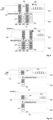
FIG. 8 is a view illustrating a state in which an attractive force and a repulsive force are generated between amovable magnet unit 111 and first and secondstationary magnet units -
FIG. 9 is a view illustrating a state in which an attractive force and a repulsive force are generated between first and second movable magnet unit 121,122 and first, second, third, and fourthstationary magnet units -
FIG. 10 is a view illustrating a state in which a magnetic pole direction of the movable magnet unit is formed in a horizontal direction according to an embodiment of the present invention. - Hereinafter, a preferred embodiment of the present invention will be described with reference to the accompanying drawings. The present disclosure may, however, be embodied in different forms and should not be construed as limited to the embodiments set forth herein. Rather, these embodiments are provided so that this disclosure will be thorough and complete, and will fully convey the scope of the inventive concept to those skilled in the art. Moreover, detailed descriptions related to well-known functions or configurations will be ruled out in order not to unnecessarily obscure subject matters of the present invention. It will be apparent to those skilled in the art that various modifications and variations can be made in the present invention without departing form the spirit or scope of the invention.
- An apparatus for locking a surgical instrument by using magnetic force according to an embodiment of the present invention performs a locking operation and unlocking operation on a
surgical instrument 10 by using attractive force and repulsive force when thesurgical instrument 10 is locked to or unlocked from an object to be locked. Hereinafter, the apparatus for locking a surgical instrument by using magnetic force according to an embodiment of the present invention will be described in detail with reference to the accompanying drawings. - As illustrated in
FIGS. 1 to 4 , a rotatingbody unit 100 according to an embodiment of the present invention is coupled with thesurgical instrument 10 through acoupling unit 20. Therotating body unit 100 extends in a horizontal direction, and thecoupling unit 10 has one end coupled to afront body 101 and the other end coupled to thesurgical instrument 10 as illustrated inFIG. 5 . As illustrated inFIG. 8 , amovement groove 102 is formed in the rotatingbody unit 100 in a longitudinal direction thereof so that a rotatinglocking unit 110 is movable in the horizontal direction. - An
elastic unit 103 is disposed inside the rotatingbody unit 100 to provide elasticity to the rotatinglocking unit 110 when the rotatinglocking unit 110 is moved along themovement groove 102 by an external force in the horizontal direction (or release direction). Accordingly, the rotatinglocking unit 110 is moved to a release position by elasticity of theelastic unit 103 disposed in an elastic space of the rotatingbody unit 100 when an external force is pushed to the rotatinglocking unit 110 as illustrated in (b) ofFIG. 8 and returned to a locking position by the elasticity when the external force is removed as illustrated in (a) ofFIG. 8 . Here, when an external force is applied to the rotatinglocking unit 110 as an example for explaining the present invention, the rotatinglocking unit 110 may be moved in the horizontal direction (release direction) and caught and fixed by a hook device (not shown) as illustrated in (b) ofFIG. 8 and returned to an original position again when the fixing of the hook device is released by an external force as illustrated in (a) ofFIG. 8 . - A
stopper unit 104 may be disposed in one area inside the rotatingbody unit 100 to exactly move a position as which a release magnetic force (or repulsive force) is generated while the rotatinglocking unit 110 is moved in the release direction as illustrated in (b) ofFIG. 8 . Thestopper unit 104 disposed inside the rotatingbody unit 100 restricts the movement of the rotatinglocking unit 110 in the release direction, so that a magnet of the rotating locking unit is disposed at a release position at which a repulsive force is applied. - On the other hand, the rotating
locking unit 110 is moved along themovement groove 102 in the release direction when an external force is applied to the rotatinglocking unit 110 or returned to an original position again in the locking direction when the external force is removed. Here, a horizontal movement assistant member may be disposed along a longitudinal direction of themovement groove 102 to allow the rotatinglocking unit 110 to be horizontally moved in the release direction or the locking direction. - The rotating
locking unit 110 according to an embodiment of the present invention is horizontally moved in a direction in which an external force is applied when an external force pushing in the horizontal direction is applied as described above. As illustrated inFIG. 8 , a movable magnet unit 111 (or first magnetic force unit) having different magnetic poles (N pole and S pole) is inserted and coupled to the rotatinglocking unit 110 in a circumferential direction of a body thereof. Thus, themovable magnet unit 111 interacts with a plurality ofstationary magnet units movable magnet unit 111 is disposed as illustrated in (a) ofFIG. 8 indicates the locking position at which an attractive force interacts, and a state in which themovable magnet unit 111 is disposed as illustrated in (b) ofFIG. 8 indicates the release position at which a repulsive force interacts. - When the rotating
locking unit 110 is disposed at the release position, the rotatingbody unit 100 and the rotatinglocking unit 110 may be rotated at a preset angle as illustrated inFIG. 1 by the repulsive force, and thus thesurgical instrument 10 is unlocked. - As illustrated in
FIGS. 1 to 4 , thestationary body unit 200 according to an embodiment of the present invention is disposed below the rotatingbody unit 100. Thestationary body unit 200 includes first and second stationary magnet seatedgrooves shaft insertion grooves - The first and second stationary magnet seated
grooves shaft insertion grooves stationary body unit 200. The first and secondstationary magnet units grooves grooves stationary magnet units movable magnet unit 111. That is, when themovable magnet unit 111 is disposed at the locking position as illustrated in (a) ofFIG. 8 , the first stationary magnet seatedgrooves 201 may be formed on the same virtual vertical line with themovable magnet unit 111. Also, when themovable magnet unit 111 is in the release position as illustrated in (b) ofFIG. 8 , the second stationary magnet seatedgrooves 202 may be formed on the same virtual vertical line with themovable magnet unit 111. Thus, the first and secondstationary magnet units grooves movable magnet unit 111 face each other to form the attractive force and the repulsive force respectively, when the first and second stationary magnet seatedgrooves movable magnet unit 111. - A stationary locking unit 210 according to an embodiment of the present invention interacts with the rotating
locking unit 110 to form a locking magnetic force (the attractive force) and a release magnetic force (the repulsive force). The stationary locking unit 210 includes the first stationary magnet unit 211 (a second magnetic force unit) and the second stationary magnet unit 212 (the second magnetic force unit). The first and secondstationary magnet units grooves FIG. 8 . The firststationary magnet unit 211 is inserted and fixed in the first stationary magnet seatedgroove 201 so that the upper side becomes the S pole, and the secondstationary magnet unit 212 is inserted and fixed in the second stationary magnet seatedgroove 202 so that the upper side becomes the N pole as illustrated in (a) ofFIG. 8 . Themovable magnet unit 111 interacting with the first and secondstationary magnet units movable magnet unit 111 and the S pole of the firststationary magnet units 211 interact with each other to generate an attractive force F 11 in the locking position. Therotating body unit 100 is locked by the generated attractive force, and thesurgical instrument 10 coupled to therotating body unit 100 is installed by the locking of therotating body unit 100. - On the other hand, the
movable magnet unit 111 moves in the horizontal direction to be located in the locking position, when an external force out of the attractive force is pushed to therotating locking unit 110 in the horizontal direction as illustrated in (b) ofFIG. 8 . The N pole of themovable magnet unit 111 and the N pole of secondstationary magnet units 212 interact with each other to generate a repulsive force F12 in the release position. Therotating body unit 100 is unlocked by the generated repulsive force, therotating body unit 100 by the unlocking may be rotated at a predetermined angle in the clockwise direction as illustrated inFIG. 1 , accordingly thesurgical instrument 10 coupled to therotating body unit 100 is uninstalled. - The above-described magnetic pole direction is not limited thereto. For example, the magnetic pole directions of the plurality of
stationary magnet units movable magnet unit 111 may be set in consideration that the attractive force and the repulsive force are applied. - When one permanent magnet is arranged as the
movable magnet unit 111 as illustrated inFIG. 8 , two permanent magnets may be arranged as the plurality of stationary magnet units. When two permanent magnets are arranged as themovable magnet unit 111 as illustrated inFIG. 8 , two permanent magnets may be arranged as the plurality of stationary magnet units. - As illustrated in (a) of
FIG. 9 , first and secondmovable magnet units rotating locking unit 110. Here, the spaced distance is determined in consideration of a locking position and a release position of the first and secondmovable magnet units stationary magnet units movable magnet units stationary magnet units grooves movable magnet units FIG. 9 , the first and secondmovable magnet units stationary magnet units movable magnet units fixed magnet units rotating body unit 100 is locked by the generated attractive force, and thesurgical instrument 10 coupled to therotating body unit 100 is installed by the locking of therotating body unit 100. Here, the generated attractive forces F21 and F22 have a magnetic force greater than that of the attractive force F11 inFIG. 8 . - When an external force greater than the attractive forces F21 and F22 is applied to the
rotating locking unit 110 in the horizontal direction as illustrated in (b) ofFIG. 9 , the first and second movable magnet units 121,122 are moved in the horizontal direction and disposed at the release position. At the release position, the first and secondmovable magnet units stationary magnet units rotating body unit 100 is unlocked by the generated repulsive force, therotating body unit 100 may be rotated by the unlocking of therotating body unit 100 at a predetermined angle in the clockwise direction as illustrated inFIG. 1 , and accordingly, thesurgical instrument 10 coupled to therotating body unit 100 is uninstalled. Here, the generated attractive forces F31 and F32 have a magnetic force greater than that of the attractive force F12 inFIG. 8 . - As described above, the first, second, third, and fourth
stationary magnet units movable magnet units - As illustrated in
FIG. 10 , amovable magnet unit 131 is arranged so that S and N poles are formed in the horizontal direction unlikeFIGS. 8 and9 . That is, themovable magnet units FIGS. 8 and9 are arranged so that the S pole and the N pole are formed in the vertical direction, and themovable magnet unit 131 ofFIG. 10 is arranged so that the S pole and the N pole are formed in the horizontal direction. As the magnetic pole of themovable magnet unit 131 is formed in the horizontal direction, onestationary magnet unit 211 corresponding to themovable magnet unit 131 may be arranged as illustrated inFIG. 10 , and twostationary magnet units 211 may be arranged to further increase the repulsive force. That is, in order to further increase the repulsive force, an additional second stationary magnet unit (not shown) spaced a predetermined distance from the firststationary magnet unit 211 to have opposite directions of magnetic poles may be arranged. - In (a) of
FIG. 10 , the attractive force F31 acts between themovable magnet unit 131 and thestationary magnet unit 211 to form a locking magnetic force, and in (b) ofFIG. 10 , as themovable magnet unit 131 is moved in the horizontal direction, the repulsive force F32 acts between themovable magnet unit 131 and thestationary magnet unit 211 to form a release magnetic force. - Also, although not shown in the drawings, a plurality of movable magnet units are spaced a predetermined distance from each other in the horizontal direction, and the stationary magnet units corresponding to the movable magnet units in pairs are arranged based on the arrangement of the movable magnet unit to form the attractive and repulsive forces in pairs, thereby increasing the attractive force and the repulsive force at the same time.
- As illustrated in
FIGS. 1 ,6 , and7 , asurgical instrument holder 221 according to an embodiment of the present invention extends upward from an end of thestationary body unit 200, and ahinge groove 221b having a shape of 'U' is formed at an upper central end. As illustrated inFIG. 1 , thecoupling unit 20 for coupling therotating body unit 100 and thesurgical instrument 10 is supported and mounted in the 'U'-shapedhinge groove 221b. As therotating locking unit 110 is unlocked as described above, therotating locking unit 110 is rotated in the clockwise direction by using the 'U'-shapedhinge groove 221b as a rotation axis. That is, thecoupling unit 20 is rotated in the clockwise direction in the 'U'-shapedhinge groove 221b. Thesurgical instrument 10 is inserted and installed in the 'U'-shaped hinge groove in a rear-to-front direction and is uninstalled from the 'U'-shaped hinge groove in a front-to-rear direction. - A rotating
body unit support 222 according to an embodiment of the present invention extends upward at a position spaced a predetermined distance from thesurgical instrument holder 221 in the horizontal direction to support therotating body unit 100 that is rotating. That is, therotating body unit 100 is rotated in the clockwise or counterclockwise direction when installed or uninstalled, and at this time, as illustrated inFIG. 2 , therotating body unit 100 supports a rotational movement of therotating body unit 100. - Each of first and second
power transmission devices FIG. 1 includes a motor and a gear to transmit a driving force to first and second shafts (not shown) inserted and fixed to first and secondshaft insertion grooves rotating body unit 100, thereby finally transmitting the driving force to thesurgical instrument 10. Thesurgical instrument 10 may perform shaft rotation and grasping as the first and secondpower transmission devices power transmission device 313 transmits a driving force when thesurgical instrument 10 is moved forward or backward. - In describing the present invention, descriptions of related art and matters obvious to those skilled in the art can be omitted, and descriptions of these omitted components (methods) and functions will be sufficiently referred to within a range without departing from the scope and spirit of the invention. It is also understood that the above-described components of the present invention have been described for convenience of description, but components that have not been described herein can be added within a range without departing from the scope and spirit of the invention.
- The component and function of each part described above have been separately described for convenience of explanation, but any one component and function may be integrated with or divided into other components as necessary.
- Although the embodiments of the present invention have been described, it is understood that the present invention should not be limited to these embodiments but various changes and modifications can be made by one ordinary skilled in the art within the spirit and scope of the present invention as hereinafter claimed. Moreover, detailed descriptions related to well-known functions or configurations will be ruled out in order not to unnecessarily obscure subject matters of the present invention.
Claims (12)
- An apparatus for locking a surgical instrument by using magnetic force, characterized by comprising:a first magnetic force unit configured to form a locking magnetic force when moving in a locking direction so that an attractive force is applied in a different direction from the locking direction and a locking operation is performed, and form a release magnetic force when moving in a release direction so that a repulsive force is applied in a different direction from the release direction and an unlocking operation is performed;a second magnetic force unit which is fixed and forms the locking magnetic force and the release magnetic force by interacting with the first magnetic force unit; anda locking unit which is locked or unlocked due to the attractive force and the repulsive force generated by the first and second magnetic force units when moving in the locking direction and the release direction, so as to install and uninstall the surgical instrument.
- The apparatus of claim 1, characterized in that the second magnetic force unit has magnetic poles that are alternately arranged along a movement direction so that the locking magnetic force and the release magnetic force are formed in the locking direction and the release direction of the first magnetic force unit.
- The apparatus of claim 2, characterized in that the first magnetic force unit and the second magnetic force unit have mutual magnetic poles opposed to each other along a movement direction of the locking unit so that attractive and repulsive forces are applied in directions perpendicular to the locking and release directions.
- The apparatus of claim 3, characterized in that the first magnetic force unit comprises a movable magnet unit that moves in the locking direction and the release direction, the second magnetic force unit comprises a plurality of stationary magnet units spaced a preset distance from each other in a horizontal direction while being relatively fixed with respect to movement of the first magnetic force unit, and the movable magnet unit is moved to a release position at which a repulsive force with the second stationary magnet unit is applied by movement as many as the preset distance in the release direction from a locking position at which an attractive force with the first stationary magnet unit is applied.
- The apparatus of claim 4, characterized in that the arrangement number of the stationary magnet units is two times greater than that of the movable magnet unit, and the attractive force and the repulsive force further increase as the mutual magnetic poles are arranged opposed to each other at the locking position and the release position.
- An apparatus for locking a surgical instrument by using magnetic force, characterized by comprising:a rotating locking unit configured to be moved and rotated in order to: apply an attractive force and a repulsive force according to movements in a locking direction and a release direction, respectively; lock a surgical instrument by formation of a locking magnetic force caused by the attractive force; and unlock the surgical instrument by formation of a release magnetic force caused by the repulsive force;a rotating body unit having a space into which the rotating locking unit is moved in the locking direction and the release direction and configured to transmit a transmitted driving force to the surgical instrument;a stationary locking unit configured to interact with the rotating locking unit to form the locking magnetic force and the release magnetic force; anda stationary body unit configured to transmit the driving force to the rotating body unit and comprising the stationary locking unit therein.
- The apparatus of claim 6, characterized in that the rotating locking unit comprises a movable magnet unit moved in the locking direction and the release direction according to body movement of the rotating locking unit, the stationary locking unit comprises a plurality of stationary magnet units spaced a preset distance from each other while being relatively fixed with respect to movement of the rotating locking unit, and locking of the rotating locking unit is released by a repulsive force as the movable magnet unit is moved as many as a preset distance from a locking position at which an attractive force with the first stationary magnet unit is applied to a release position at which a repulsive force with the second stationary magnet unit is applied in the release direction.
- The apparatus of claim 7, characterized in that the plurality of stationary magnet units have magnetic poles that are alternately arranged along a movement direction so as to form the locking magnetic force and the release magnetic force in the locking direction and the release direction of the rotating locking unit.
- The apparatus of claim 8, characterized in that the movable magnet unit and the plurality of stationary magnet units have mutual magnetic poles opposed to each other along a movement direction of the locking unit so that attractive and repulsive forces are applied in directions perpendicular to the locking and release directions.
- The apparatus of claim 6, characterized in that the stationary body unit comprises:a surgical instrument holder having a 'U'-shaped hinge groove, in an end thereof, by which a coupling unit extending upward from an end of the stationary body unit to couple the surgical instrument with the rotating body unit is supported and mounted, so that the surgical instrument is inserted and installed in the 'U'-shaped hinge groove in a rear-to-front direction, and locking of the surgical instrument is released as the rotating locking unit is rotated by using the 'U'-shaped hinge groove as a rotation axis according to the release magnetic force; anda rotating body support extending upward from a position spaced a predetermined distance from the surgical instrument holder in the horizontal direction to support the rotating body unit.
- The apparatus of claim 7, characterized in that the stationary body unit comprises:a first stationary magnet seated groove in which the first stationary magnet unit is inserted and seated; anda second stationary magnet seated groove which is spaced a preset distance from the first stationary magnet seated groove and in which the second stationary magnet unit is inserted and seated,wherein in the first and second stationary magnet seated grooves, mutual magnetic poles of the first and second stationary magnet units and the movable magnet unit are arranged opposed to each other along a movement direction of the rotating locking unit so that an attractive force and a repulsive force are applied in a direction perpendicular to the locking direction and the release direction.
- The apparatus of claim 10, characterized in that the rotating locking unit is rotated at a preset angle by using the 'U'-shaped hinge groove as a rotation axis by a release magnetic force formed in a vertical direction to a release direction as horizontally moved in the release direction to release the locking, and the surgical instrument is uninstalled from the 'U'-shaped hinge groove in a front-to-rear direction as the locking of the rotating locking unit is released.
Applications Claiming Priority (2)
| Application Number | Priority Date | Filing Date | Title |
|---|---|---|---|
| KR1020200151606A KR102463770B1 (en) | 2020-11-13 | 2020-11-13 | Locking apparatus of surgical instruments using magnetic force |
| PCT/KR2021/016390 WO2022103165A1 (en) | 2020-11-13 | 2021-11-11 | Apparatus for locking surgical instrument by using magnetic force |
Publications (2)
| Publication Number | Publication Date |
|---|---|
| EP4245247A1 true EP4245247A1 (en) | 2023-09-20 |
| EP4245247A4 EP4245247A4 (en) | 2024-10-09 |
Family
ID=81601574
Family Applications (1)
| Application Number | Title | Priority Date | Filing Date |
|---|---|---|---|
| EP21892332.4A Pending EP4245247A4 (en) | 2020-11-13 | 2021-11-11 | Apparatus for locking surgical instrument by using magnetic force |
Country Status (5)
| Country | Link |
|---|---|
| US (1) | US12605224B2 (en) |
| EP (1) | EP4245247A4 (en) |
| KR (1) | KR102463770B1 (en) |
| CN (1) | CN116847795A (en) |
| WO (1) | WO2022103165A1 (en) |
Families Citing this family (1)
| Publication number | Priority date | Publication date | Assignee | Title |
|---|---|---|---|---|
| US20250090260A1 (en) * | 2023-09-19 | 2025-03-20 | Roen Surgical, Inc. | Surgical instruments holding apparatus |
Family Cites Families (16)
| Publication number | Priority date | Publication date | Assignee | Title |
|---|---|---|---|---|
| US7090683B2 (en) * | 1998-02-24 | 2006-08-15 | Hansen Medical, Inc. | Flexible instrument |
| DE202005021283U1 (en) * | 2005-03-09 | 2007-10-04 | Fiedler, Joachim | Magnetic holder |
| KR20070010992A (en) | 2005-07-20 | 2007-01-24 | 주식회사 팬택앤큐리텔 | Battery removable structure of mobile communication terminal |
| US8491626B2 (en) | 2010-06-02 | 2013-07-23 | Covidien Lp | Apparatus for performing an electrosurgical procedure |
| US8628529B2 (en) * | 2010-10-26 | 2014-01-14 | Ethicon Endo-Surgery, Inc. | Surgical instrument with magnetic clamping force |
| KR20130102894A (en) * | 2012-03-08 | 2013-09-23 | 주식회사 아이폼 | Detachable handle of cooking vessels |
| KR101403766B1 (en) | 2012-11-02 | 2014-06-13 | 주식회사 야스 | Magnetic chucker for substrate |
| US10368892B2 (en) | 2013-11-22 | 2019-08-06 | Ethicon Llc | Features for coupling surgical instrument shaft assembly with instrument body |
| KR101502446B1 (en) | 2014-01-28 | 2015-03-13 | 주식회사 고영테크놀러지 | Spine surgical instrument and surgical robot system employing the same |
| KR101762503B1 (en) | 2014-09-01 | 2017-07-28 | 송명호 | Magnet Doorcloser |
| EP3034019B1 (en) * | 2014-12-15 | 2017-06-28 | University Of Dundee | Medical instrument for grasping tissue |
| KR101661710B1 (en) * | 2015-09-01 | 2016-10-04 | 킴스쿡 주식회사 | A Detachable Handle for Cooking Vessels |
| DE102016112214A1 (en) * | 2016-07-04 | 2018-01-04 | Fabian Linkert | locking system |
| US10335957B2 (en) * | 2017-04-25 | 2019-07-02 | Ati Industrial Automation, Inc. | Magnetically activated tool changer |
| JP2020064714A (en) * | 2018-10-15 | 2020-04-23 | 本田技研工業株式会社 | Connector device |
| KR102146409B1 (en) | 2019-06-13 | 2020-08-20 | (주)군월드 | Electromagnet door lock |
-
2020
- 2020-11-13 KR KR1020200151606A patent/KR102463770B1/en active Active
-
2021
- 2021-11-11 WO PCT/KR2021/016390 patent/WO2022103165A1/en not_active Ceased
- 2021-11-11 CN CN202180079163.1A patent/CN116847795A/en active Pending
- 2021-11-11 US US18/036,871 patent/US12605224B2/en active Active
- 2021-11-11 EP EP21892332.4A patent/EP4245247A4/en active Pending
Also Published As
| Publication number | Publication date |
|---|---|
| KR102463770B1 (en) | 2022-11-04 |
| KR20220065276A (en) | 2022-05-20 |
| WO2022103165A1 (en) | 2022-05-19 |
| US20230404697A1 (en) | 2023-12-21 |
| EP4245247A4 (en) | 2024-10-09 |
| US12605224B2 (en) | 2026-04-21 |
| CN116847795A (en) | 2023-10-03 |
Similar Documents
| Publication | Publication Date | Title |
|---|---|---|
| WO2023284515A1 (en) | Instrument drive transmission mechanism and assembly mechanism of surgical robot | |
| EP3750226B1 (en) | Method and system for magnetically latching a charging port to an electric vehicle | |
| US12605224B2 (en) | Apparatus for locking surgical instrument by using magnetic force | |
| CN102890321B (en) | For microscopical conversion equipment | |
| EP3672030A1 (en) | Valve, in particular expansion valve | |
| JP7547604B2 (en) | Unlocking mechanism, bracket assembly, and method for unlocking and locking up a battery pack | |
| EP2891737A2 (en) | Drum type washing machine | |
| JP2021507475A (en) | Conversion force latching system | |
| CN102444328B (en) | Electronic ring latch | |
| CN109314343B (en) | Electrical plug connection | |
| CN217828059U (en) | Instrument driving transmission mechanism and assembling mechanism of surgical robot | |
| CN108604489B (en) | Bistable electromechanical actuator | |
| CN214434482U (en) | Quick plug devices, actuators and surgical robots | |
| US11648829B2 (en) | Assembly and method for moving a cover | |
| CN114587596A (en) | Quick plug device, actuating mechanism and surgical robot | |
| CN104425910B (en) | Connecting component and controlling cable connecting structure | |
| JP2018088771A (en) | Vibration power generator | |
| CN112490755B (en) | A docking device and end drive mechanism | |
| US20210263234A1 (en) | Optical receptacle and optical connector module using the same | |
| CN209687942U (en) | Driver and its integral type shaft coupling | |
| US20260081695A1 (en) | Cantilever constraining feature for optical transceiver module | |
| KR20090011671A (en) | Reciprocating Power Unit | |
| EP3223117B1 (en) | Operation device and method for manufacturing the same | |
| CN113839260B (en) | Device and electronic equipment convenient to installation is dismantled | |
| KR20210028474A (en) | Apparatus for assembling and disassembling connector |
Legal Events
| Date | Code | Title | Description |
|---|---|---|---|
| STAA | Information on the status of an ep patent application or granted ep patent |
Free format text: STATUS: THE INTERNATIONAL PUBLICATION HAS BEEN MADE |
|
| PUAI | Public reference made under article 153(3) epc to a published international application that has entered the european phase |
Free format text: ORIGINAL CODE: 0009012 |
|
| STAA | Information on the status of an ep patent application or granted ep patent |
Free format text: STATUS: REQUEST FOR EXAMINATION WAS MADE |
|
| 17P | Request for examination filed |
Effective date: 20230605 |
|
| AK | Designated contracting states |
Kind code of ref document: A1 Designated state(s): AL AT BE BG CH CY CZ DE DK EE ES FI FR GB GR HR HU IE IS IT LI LT LU LV MC MK MT NL NO PL PT RO RS SE SI SK SM TR |
|
| DAV | Request for validation of the european patent (deleted) | ||
| DAX | Request for extension of the european patent (deleted) | ||
| A4 | Supplementary search report drawn up and despatched |
Effective date: 20240905 |
|
| RIC1 | Information provided on ipc code assigned before grant |
Ipc: A61B 34/30 20160101ALI20240830BHEP Ipc: A61B 17/00 20060101ALI20240830BHEP Ipc: A61B 17/28 20060101ALI20240830BHEP Ipc: A61B 17/29 20060101ALI20240830BHEP Ipc: A61B 50/20 20160101AFI20240830BHEP |