EP4245193A1 - Commodity removal device, and commodity removal system - Google Patents
Commodity removal device, and commodity removal system Download PDFInfo
- Publication number
- EP4245193A1 EP4245193A1 EP21910184.7A EP21910184A EP4245193A1 EP 4245193 A1 EP4245193 A1 EP 4245193A1 EP 21910184 A EP21910184 A EP 21910184A EP 4245193 A1 EP4245193 A1 EP 4245193A1
- Authority
- EP
- European Patent Office
- Prior art keywords
- item
- take
- port
- unit
- out port
- Prior art date
- Legal status (The legal status is an assumption and is not a legal conclusion. Google has not performed a legal analysis and makes no representation as to the accuracy of the status listed.)
- Pending
Links
Images










Classifications
-
- G—PHYSICS
- G07—CHECKING-DEVICES
- G07F—COIN-FREED OR LIKE APPARATUS
- G07F11/00—Coin-freed apparatus for dispensing, or the like, discrete articles
- G07F11/02—Coin-freed apparatus for dispensing, or the like, discrete articles from non-movable magazines
- G07F11/04—Coin-freed apparatus for dispensing, or the like, discrete articles from non-movable magazines in which magazines the articles are stored one vertically above the other
- G07F11/16—Delivery means
- G07F11/165—Delivery means using xyz-picker or multi-dimensional article picking arrangements
-
- G—PHYSICS
- G07—CHECKING-DEVICES
- G07F—COIN-FREED OR LIKE APPARATUS
- G07F11/00—Coin-freed apparatus for dispensing, or the like, discrete articles
- G07F11/005—Special arrangements for insuring that only one single article may be dispensed at a time
-
- G—PHYSICS
- G07—CHECKING-DEVICES
- G07F—COIN-FREED OR LIKE APPARATUS
- G07F11/00—Coin-freed apparatus for dispensing, or the like, discrete articles
- G07F11/46—Coin-freed apparatus for dispensing, or the like, discrete articles from movable storage containers or supports
-
- G—PHYSICS
- G07—CHECKING-DEVICES
- G07F—COIN-FREED OR LIKE APPARATUS
- G07F9/00—Details other than those peculiar to special kinds or types of apparatus
- G07F9/10—Casings or parts thereof, e.g. with means for heating or cooling
-
- G—PHYSICS
- G06—COMPUTING OR CALCULATING; COUNTING
- G06Q—INFORMATION AND COMMUNICATION TECHNOLOGY [ICT] SPECIALLY ADAPTED FOR ADMINISTRATIVE, COMMERCIAL, FINANCIAL, MANAGERIAL OR SUPERVISORY PURPOSES; SYSTEMS OR METHODS SPECIALLY ADAPTED FOR ADMINISTRATIVE, COMMERCIAL, FINANCIAL, MANAGERIAL OR SUPERVISORY PURPOSES, NOT OTHERWISE PROVIDED FOR
- G06Q20/00—Payment architectures, schemes or protocols
- G06Q20/08—Payment architectures
- G06Q20/20—Point-of-sale [POS] network systems
-
- G—PHYSICS
- G07—CHECKING-DEVICES
- G07G—REGISTERING THE RECEIPT OF CASH, VALUABLES, OR TOKENS
- G07G1/00—Cash registers
- G07G1/0018—Constructional details, e.g. of drawer, printing means, input means
Definitions
- the present disclosure relates to an item take-out apparatus and an item take-out system that allow a user to take out an item stored in the apparatus to the outside of the apparatus.
- PATENT LITERATURE 1 discloses a vending machine that stores items in a plurality of storage racks, and takes out by an arm, from a storage rack, an item selected by a user and discharges the item to the outside of the machine through an item pick-up port.
- the apparatus is installed on a counter of a store with the item pick-up port facing a customer.
- the clerk faces the customer across the counter, the clerk present on the back side of the apparatus cannot take out an item from the item pick-up port on the front side of the apparatus.
- the present disclosure is made in view of the conventional art including the above problem, and one object of the present disclosure is to provide an item take-out apparatus and an item take-out system capable of dealing with various styles of selling items in stores.
- An item take-out apparatus is an apparatus from which a user takes out an item.
- the apparatus includes: a storage unit configured to store items therein; a plurality of take-out ports through which the user takes out an item from inside the item take-out apparatus; and a transport unit configured to extract an item from the storage unit and transport the item to any of the plurality of take-out ports.
- the transport unit may transport an item designated by the user to a take-out port, through which the user takes out the item, among the plurality of take-out ports.
- the user includes a clerk and a customer, for example.
- At least one take-out port may be disposed in each of a plurality of surfaces of a housing of the item take-out apparatus.
- At least one take-out port may be disposed in each of at least two surfaces out of four side surfaces, an upper surface and a lower surface that constitute a housing of the item take-out apparatus.
- At least one of the plurality of take-out ports may be disposed in an exterior wall of a store so that the user takes out the item from outside the store.
- the apparatus may further include an operation unit for the user to designate an item and/or a take-out port.
- the apparatus may further include a communication unit configured to receive information indicating the item and the take-out port designated by the user from an external apparatus including an operation unit for the user to designate an item and a take-out port.
- the transport unit may transport the designated item to the designated take-out port.
- the apparatus may further include a memory that stores information indicating correspondence between kinds of the items and the plurality of take-out ports.
- a take-out port corresponding to the item may be specified based on the information stored in the memory and the transport unit may transport the item to a take-out port corresponding to the item.
- the apparatus may further include: a plurality of operation units; and a memory that stores information indicating correspondence between the respective operation units and the plurality of take-out ports.
- a take-out port corresponding to the operation unit is specified based on the information stored in the memory and the transport unit may transport the item to a take-out port corresponding to the operation unit.
- the transport unit may transport the item to the take-out port on condition that it has been confirmed that a customer who purchases the item has the purchase eligibility.
- the transport unit may transport the item to the take-out port on condition that information indicating that the customer has the purchase eligibility has been inputted by using the operation unit.
- the apparatus may further include a reading device configured to read eligibility information on the purchase eligibility from a medium storing the eligibility information.
- the transport unit may transport the item to the take-out port on condition that the reading device has read the eligibility information from a medium owned by the customer.
- the apparatus may further include a communication unit configured to receive, from an external apparatus that reads eligibility information on the purchase eligibility from a medium storing the eligibility information, information indicating whether or not the eligibility information has been read from the medium.
- the transport unit may transport the item to the take-out port on condition that the communication unit has received information indicating that the eligibility information has been read from a medium owned by the customer.
- the storage unit may have a storage port and an extraction port, and store therein items received from the storage port in such a manner that only one item, among a plurality of items being stored therein, is extracted from the extraction port to outside the storage unit.
- the transport unit may transport the one item extracted from the extraction port, to the take-out port.
- the transport unit may further include: a holding unit configured to extract an item from the extraction port of the storage unit; a rotation unit configured to rotate the holding unit; and a movement unit configured to move the holding unit.
- the holding unit may include: a tray on which the item can be placed; and a hook projecting upward from the tray.
- the storage unit may store therein a plurality of items by stacking the items in an up-down direction in such a manner that entire side surface of the lowermost item is exposed from the storage unit in a direction for extracting the lowermost item while exposing a portion of a lower surface and a portion of a back surface of the lowermost item from the storage unit.
- the transport unit may extract the lowermost item from the storage unit with the hook of the holding unit being caught on the back surface of the lowermost item, and place the extracted item on the tray to transport the item.
- the take-out port may further include a placement part on which an item to be taken out from the take-out port is placed, and a groove may be formed in the placement part.
- the transport unit may cause the tray to enter a space beneath the placement part such that the item on the tray is transferred onto the placement part while the hook passes into the groove, move downward to a position where the hook is separated from the item placed on the placement part and move backward, to transport the item to the take-out port.
- An item take-out system is a system from which a user takes out an item.
- the system includes: a storage unit configured to store items therein; a plurality of take-out ports through which the user takes out an item from inside the item take-out apparatus; and a transport unit configured to extract an item from the storage unit and transport the item to any of the plurality of take-out ports.
- the transport unit may transport an item designated by the user to a take-out port, through which the user takes out the item, among the plurality of take-out ports.
- the user includes a clerk and a customer, for example.
- the item take-out apparatus can deal with various styles of selling items in stores.
- FIG. 1 is a schematic diagram illustrating an outline of an item take-out apparatus 1 according to the present embodiment.
- the item take-out apparatus 1 is installed in a store in which items are sold, and is used by a clerk or a customer (hereinafter referred to as "user") to take out an item that the customer purchases.
- Coordinate axes in the drawings showing the configuration of the item take-out apparatus 1 of the present embodiment indicate the relationship of the components of the item take-out apparatus 1 shown in each drawing.
- a Z-axis direction corresponds to an up-down direction
- an XY plane corresponds to a horizontal plane.
- the directions shown in each drawing are examples and do not limit the installation method for the respective components and the directions of the components during operations.
- a plurality of kinds of items are stored in the item take-out apparatus 1.
- the item take-out apparatus 1 is provided with a plurality of take-out ports 2 for the user to take out items from the item take-out apparatus 1.
- FIG. 1 shows an example of take-out ports 2 of the item take-out apparatus 1.
- a take-out port 2 is disposed in at least one surface out of six surfaces including four side surfaces (i.e., a front surface, a back surface, a left-side surface, and a right-side surface), an upper surface, and a lower surface of the item take-out apparatus 1.
- Take-out ports 2 may be disposed in a plurality of surfaces constituting a housing of the item take-out apparatus 1.
- One or a plurality of take-out ports 2 are disposed in one surface.
- a plurality of take-out ports 2 may allow the user to take out an item from the item take-out apparatus 1 in a plurality of different directions.
- a surface in which the take-out port 2 is formed is not particularly limited. Also, the positions and the number of the take-out ports 2 in each surface are not particularly limited.
- the take-out ports 2 are disposed in the item take-out apparatus 1 according to the usage method of the item take-out apparatus 1 in the store.
- the item take-out apparatus 1 can receive an input of information designating an item, and an input of information designating a take-out port 2 from which the designated item is taken out from the apparatus (A1).
- the information inputting method is not limited.
- the item take-out apparatus 1 may include an operation unit by which the user performs the designation, and the designation information may be inputted to the item take-out apparatus 1 from the operation unit.
- the user may operate an operation unit included in an external apparatus such as an operation terminal or a cash register to perform the designation, and the designation information is inputted to the item take-out apparatus 1 from the external device.
- the item take-out apparatus 1 transports the item designated from among the items stored in the apparatus, to the designated take-out port 2 (A2).
- the user can take out the desired item from the desired take-out port 2 (A3).
- Each take-out port 2 may be always opened, or may be opened and closed by a shutter.
- the shutter may be slidably moved to open and close the take-out port 2.
- the shutter may be pivoted inward and/or outward with respect to the take-out port 2 to open and close the take-out port 2.
- the shutter may be manually opened and closed by the user.
- the shutter may be automatically opened and closed by the item take-out apparatus 1.
- the shutters of the take-out ports 2 may be usually closed, and after transporting the designated item 100 to the designated take-out port 2, the item take-out apparatus 1 may automatically open the shutter of the take-out port 2 to which the item 100 has been transported.
- a sensor not shown in FIG. 1 may be disposed at the take-out port 2, and the item take-out apparatus 1 may automatically close the shutter upon detecting, by the sensor, that the item 100 has been taken out from the take-out port 2.
- the user may not necessarily designate both an item and a take-out port 2, and may designate only an item.
- the item take-out apparatus 1 may automatically specifies a take-out port 2 corresponding to the designated item, and transport the designated item to the specified take-out port 2.
- information on correspondence between the kinds of items and the take-out ports 2 may be prepared in advance, and a take-out port 2 may be specified according to an item designated by the user, based on the information. It may be set that an item, for which a customer is required to satisfy a specific condition such as an age restriction to purchase the item, is transported to a take-out port 2 facing a clerk 200.
- a plurality of operation units to be input sources of item designating information may be disposed, information indicating correspondence between the operation units and the take-out ports 2 may be prepared in advance, and a take-out port 2 corresponding to an operation unit by which an item designating operation has been performed may be specified based on the information.
- the take-out port 2 may be specified by the item take-out apparatus 1, or may be specified by an external apparatus connected to the item take-out apparatus 1.
- the configuration of the item take-out apparatus 1 is not limited thereto.
- the item take-out apparatus 1 shown in FIG. 1 has a height that allows an external apparatus such as a cash register or an operation terminal to be disposed and used on the upper surface thereof, the height of the item take-out apparatus 1 is not particularly limited. Also, the dimensions of the item take-out apparatus 1 in the left-right direction and front-rear direction are not particularly limited.
- FIG. 2 is a schematic diagram illustrating examples of the item take-out apparatus 1.
- FIG. 2 shows a counter-type item take-out apparatus 1 installed on the floor, and a hanging-type item take-out apparatus 1 disposed at a position away from the floor.
- the hanging-type item take-out apparatus 1 may be hung from the ceiling of the store, or may be fixed to a wall surface of the store.
- the clerk 200 may serve a customer 300 over the counter-type item take-out apparatus 1 and take out an item that the customer 300 purchases, from a take-out port 2 of the item take-out apparatus 1.
- the item take-out apparatus 1 may have a take-out port 2 in the side surface on the customer 300 side, and the customer may take out the item from the take-out port 2 by himself/herself.
- the clerk 200 may take out an item 100 that the customer 300 purchases, from a take-out port 2 of the hanging-type item take-out apparatus 1.
- the hanging-type item take-out apparatus 1 may have a take-out port 2 in the lower surface thereof, and the clerk 200 may take out the item 100 from the lower surface of the item take-out apparatus 1.
- FIG. 3 is a block diagram schematically showing the configuration of the item take-out apparatus 1.
- the item take-out apparatus 1 includes a transport unit 10, a control unit 20, a communication unit 30, and a memory 40.
- the transport unit 10 extracts an item from a storage unit inside the apparatus and transports the item to a take-out port 2, which will be described in detail later.
- the memory 40 is a non-volatile storage apparatus.
- the memory 40 is used to store information necessary for operations of the item take-out apparatus 1. For example, information indicating correspondence between a plurality of storage units inside the apparatus and the kinds of items stored in the respective storage units, is stored in the memory 40. For example, information indicating correspondence between a plurality of kinds of items and a plurality of take-out ports 2 is stored in the memory 40. For example, information indicating correspondence between a plurality of operation units and a plurality of take-out ports 2 is stored in the memory 40.
- the plurality of operation units may include an operation unit of an external apparatus.
- the communication unit 30 exchanges information with external apparatuses through wired communication or wireless communication.
- an item take-out system includes the external apparatuses and the item take-out apparatus 1.
- An operation terminal 50 is an example of the external apparatuses.
- the communication unit 30 can receive information indicating an item and a take-out port 2 designated by the user, from the operation terminal 50 serving as an operation unit.
- a tablet-type computer terminal including an operation unit and a display unit is used as the operation terminal 50.
- a cash register including an operation unit and a display unit is used as the operation terminal 50.
- the control unit 20 Based on the information received by the communication unit 30 and the information stored in the memory 40, the control unit 20 specifies the position of a storage unit in which the item is stored and a take-out port 2 to be a destination of the item.
- the control unit 20 controls the transport unit 10 to extract the item from the specified storage unit, and transport the item to the specified take-out port 2.
- the control unit 20 controlling the respective units based on the information inputted from outside and the information stored in the memory 40, realizes the functions and operations of the item take-out apparatus 1 described in the present embodiment.
- the operation terminal 50 may be connected to a payment apparatus 60 that performs a payment process on an item price.
- a cash register serving as the payment apparatus 60 is connected to a computer terminal serving as the operation terminal 50.
- a money handling apparatus serving as the payment apparatus 60 is connected to a cash register serving as the operation terminal 50.
- the payment apparatus 60 is not limited to an apparatus performing a cash payment process, and may be an apparatus performing an electronic payment process, instead of or in addition to the cash payment process.
- the payment apparatus 60 may perform the item price payment process by an electronic payment using a debit card, a credit card, a prepaid card, electronic money, etc.
- the item take-out apparatus 1 may transport the item to the take-out port 2, on the condition that the payment apparatus 60 has completed the item price payment process. For example, the payment apparatus 60 inputs, to the operation terminal 50, information indicating that the payment for purchasing an item has been completed, and the operation terminal 50 inputs, to the item take-out apparatus 1, information designating the item that has been purchased. Then, the item take-out apparatus 1 transports the designated item to the take-out port 2.
- At least one of the operation terminal 50 and the payment apparatus 60 may serve as a confirmation apparatus that confirms whether or not a customer has purchase eligibility for purchasing an item.
- the purchase eligibility is required for some items, and these items can be purchased only by customers having the purchase eligibility.
- the memory 40 information indicating the kinds of items for which the purchase eligibility is required is stored in advance.
- the item take-out apparatus 1 determines whether or not the purchase eligibility is required for the item designated by using the operation terminal 50. Upon detecting that the purchase eligibility is required for the designated item, the item take-out apparatus 1 performs a notification process for requesting confirmation of whether or not the customer has the purchase eligibility. For example, information instructing the operation for confirming the purchase eligibility of the customer is displayed on the display unit of the operation terminal 50.
- the confirmation apparatus performs a confirmation process of confirming with a certificate that the age of the purchaser exceeds a predetermined age.
- a driver's license or the like issued by a public organization is used as the certificate.
- the clerk recognizes that the confirmation process is required and then asks the customer purchasing the item, for which purchase eligibility is required, to present a certificate.
- the clerk visually checks the certificate and performs a predetermined operation by using the confirmation apparatus to complete the confirmation process.
- the confirmation apparatus may include a reading device capable of reading information on the certificate.
- the customer uses the reading device to read the information on the certificate.
- the confirmation apparatus determines whether or not the customer has the purchase eligibility for the item to complete the confirmation process. If the purchase eligibility is recorded on a card type medium such as a magnetic card or an IC card, the confirmation process is performed by using a reading device that reads information from the medium. If the purchase eligibility is to be confirmed by using a portable communication terminal such as a smartphone of the customer, the confirmation process is performed by using a reading device capable of obtaining information from the portable communication terminal.
- the confirmation apparatus confirms that the customer has the purchase eligibility for the item, through the reading device or the visual check by the clerk as described above, to complete the confirmation process.
- the result of the confirmation process is inputted to the item take-out apparatus 1 from the confirmation apparatus, i.e., at least one of the operation terminal 50 and the payment apparatus 60, having finished the confirmation process.
- the item take-out apparatus 1 transports the item to the take-out port 2 on the condition that it has been confirmed by using the operation terminal 50 and/or the payment apparatus 60 that the customer has the purchase eligibility for the item.
- the item take-out apparatus 1 may not necessarily detect an item for which purchase eligibility is required, and the operation terminal 50 or the payment apparatus 60 may start the confirmation process upon detecting an item for which purchase eligibility is required. In this case, for example, the operation terminal 50 or the payment apparatus 60 obtains the result of the confirmation process, and then the operation terminal 50 inputs information designating the item to the item take-out apparatus 1. After receiving the information, the item take-out apparatus 1 can transport the designated item to the take-out port 2.
- the configuration shown in FIG. 3 is an example, and does not limit the configuration of the item take-out apparatus 1 and the apparatuses connected to and used with the item take-out apparatus 1.
- Distributed or integrated forms of each apparatus are not limited to the above example, and all or some of the forms may be distributed or integrated functionally or physically in any unit depending on various loads, use statuses, or the like.
- the item take-out apparatus 1 may include an operation unit, and the item take-out apparatus 1 may realize the function of the operation terminal 50 described in the present embodiment.
- the operation terminal 50 may also serve as the payment apparatus 60.
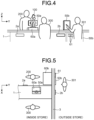
- FIG. 4 is a schematic diagram illustrating an example of the item take-out apparatus 1 used in the store.
- the item take-out apparatus 1 is installed at a checkout counter of the store, and is used with a plurality of operation terminals 50 (50a, 50b) and a plurality of payment apparatuses 60 (60a, 60b) connected to the apparatus 1.
- the clerk 200 faces the customer 300 across the item take-out apparatus 1 that separates them.
- the item take-out apparatus 1 has a plurality of take-out ports 2 (2a, 2b).
- the take-out port 2a is disposed on the side surface of the clerk 200 side
- the take-out port 2b is disposed on the side surface of the customer 300 side.
- the clerk 200 serving the customer 300 operates the operation terminal 50a installed on the item take-out apparatus 1 to designate an item that the customer 300 purchases.
- the clerk 200 performs a payment process for the price of the item that the customer 300 purchases, by using the operation terminal 50a and the payment apparatus 60a.
- the clerk 200 deposits cash received from the customer 300 into the payment apparatus 60a, and returns change dispensed from the payment apparatus 60a to the customer 300 according to need.
- the item price payment process may be performed by electronic payment in the payment apparatus 60.
- a confirmation process for the purchase eligibility is performed.
- the clerk 200 asks the customer 300 to present a certificate.
- the clerk 200 visually checks the certificate to confirm that the customer 300 has the purchase eligibility for the item.
- the customer 300 causes the reading device connected to the operation terminal 50a or the payment apparatus 60a to read information from the certificate, for example. After performing the confirmation process through the visual check or the reading device, the item can be taken out from the item take-out apparatus 1 on the condition that a confirmation result indicating that the customer 300 has the purchase eligibility has been obtained.
- the control unit 20 of the item take-out apparatus 1 specifies the storage unit in which the item designated by using the operation terminal 50a is stored, and specifies the take-out port 2a associated with the operation terminal 50a.
- the control unit 20 controls the transport unit 10 to extract the item from the specified storage unit, and transport the item to the take-out port 2a.
- the control unit 20 performs a notification process for notifying the clerk 200 that the item has been transported to the take-out port 2a.
- a notification process for example, information indicating that the item can be taken out from the take-out port 2a is displayed on the display unit of the operation terminal 50a.
- the clerk 200 Upon checking the display, the clerk 200 takes out the item 100 from the take-out port 2a and passes the item 100 to the customer 300 as shown in FIG. 4 to complete the transaction.
- a self-transaction in which a customer 301 purchases an item by himself/herself without being served by the clerk 200, may also be performed.
- a payment apparatus 60b is installed in the counter.
- An inlet/outlet 61 of the payment apparatus 60b is disposed on the side surface, of the counter, including the take-out port 2b for self-transaction.
- the customer 301 can deposit banknotes and coins to be paid for the item, from the inlet/outlet 61, into the payment apparatus 60b.
- the customer 301 can receive banknotes and coins dispensed as change from the inlet/outlet 61 of the payment apparatus 60b.
- the customer 301 selects an item by operating the operation terminal 50b, and performs a payment process for the price of the item by using the payment apparatus 60b. For example, the customer 301 deposits cash to be paid for purchasing the item into the payment apparatus 60b, and receives change dispensed from the payment apparatus 60b. For example, the customer 301 operates the operation terminal 50b to pay for the item by electronic payment.
- the operation terminal 50b When the customer 301 has operated the operation terminal 50b and selected an item for which purchase eligibility is required, the operation terminal 50b starts a confirmation process for the purchase eligibility.
- the confirmation process is performed by the customer 300 by causing the reading device of the operation terminal 50b to read information from a certificate of the customer. Only when the confirmation result of the confirmation process indicates that the customer 301 has the purchase eligibility, the customer 301 is allowed to take out the item from the item take-out apparatus 1.
- the control unit 20 of the item take-out apparatus 1 specifies the storage unit in which the item designated by the customer 301 through the operation terminal 50b is stored, and specifies the take-out port 2b associated with the operation terminal 50b.
- the control unit 20 controls the transport unit 10 to extract the item from the specified storage unit, and transport the item to the take-out port 2b.
- the control unit 20 displays information indicating that the item can be taken out from the take-out port 2b, on the display unit of the operation terminal 50b to notify the customer 301 of this fact.
- the customer 301 takes out the item from the take-out port 2b to complete the transaction.
- a semi-self-transaction in which the clerk 200 serving a customer performs an item designating operation and an item price payment process, and the customer takes out the item from the take-out port 2, may also be performed.
- the clerk 200 performs an operation of designating an item that the customer purchases and a payment for the price of the item by using the operation terminal 50a and the payment apparatus 60a.
- the clerk 200 operates the operation terminal 50a to perform an operation of designating the take-out port 2b as a destination of the item.
- the control unit 20 of the item take-out apparatus 1 controls the transport unit 10 to transport the item to the take-out port 2b, on the condition that the payment process has been completed in the payment apparatus 60a.
- the customer takes out the item from the take-out port 2b to complete the transaction.
- a semi-self-transaction in which the clerk 200 serving a customer performs an item designating operation, and the customer performs an item price payment process and takes out the item from the take-out port 2, may also be performed.
- the clerk 200 operates the operation terminal 50a to designate an item that the customer purchases.
- the clerk 200 performs a predetermined operation by using the operation terminal 50a, whereby information indicating the price of the item is inputted to the payment apparatus 60b, and the take-out port 2b is designated as a destination of the item.
- the customer performs a payment process by using the payment apparatus 60b to pay for the item.
- the control unit 20 of the item take-out apparatus 1 controls the transport unit 10 to transport the item to the take-out port 2b, on the condition that the payment process has been completed in the payment apparatus 60b.
- the customer takes out the item from the take-out port 2b to complete the transaction.
- a semi-self-transaction in which a customer performs an item designating operation by himself/herself, and the clerk 200 performs an item price payment process and passes the item to the customer, may also be performed.
- the customer designates an item by operating the operation terminal 50b.
- information indicating the designated item is inputted to the operation terminal 50a, and the take-out port 2a is designated as a destination of the item.
- the clerk 200 performs an item price payment process for the item by using the payment apparatus 60a based on the information received in the operation terminal 50a.
- the control unit 20 of the item take-out apparatus 1 controls the transport unit 10 to transport the item to the take-out port 2a, on the condition that the payment process has been completed in the payment apparatus 60a.
- the clerk 200 take outs the item from the take-out port 2a and passes the item to the customer to complete the transaction.
- FIG. 5 is a schematic diagram illustrating an example of the item take-out apparatus 1 having take-out ports 2 inside and outside a store.
- the apparatuses are viewed from above.
- the item take-out apparatus 1 is installed in the store near an exterior wall 3 of the store, and the take-out port 2b is disposed in the exterior wall 3 so that a customer can take out an item from outside the store.
- the payment apparatus 60b is installed in the store near the exterior wall 3 of the store, and the inlet/outlet 61 is disposed on the exterior wall 3 so that the customer can deposit and receive cash from outside the store.
- the operation terminal 50b including the operation unit and the display unit is fixed to the exterior wall of the store so that the customer can operate it from outside the store.
- the clerk 200 can serve and deal with the customer 300 inside the store as described in FIG. 4 . Moreover, the clerk 200 can deal with the customer 301 outside the store. In this case, the semi-self-transaction, in which at least one of designation of an item, payment for the item price, and reception of the item is performed by the customer 301 outside the store, is performed in the same manner as described in FIG. 4 . Also, for example, the customer 301 outside the store can perform the self-transaction in the same manner as described in FIG. 4 , in which the customer 301 designates the item by using the operation terminal 50b, pays for the item by using the payment apparatus 60b and receives the item from the take-out port 2b. This allows the customer 301 to purchase the item even during outside business hours of the store.
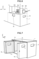
- FIG. 6 is a schematic diagram illustrating an example of the item take-out apparatus 1 having take-out ports 2 outside a store.
- the item take-out apparatus 1 is placed in the store near an exterior wall of the store, and a plurality of take-out ports 2 (2a, 2b) are disposed in exterior walls so that a customer can take out an item from outside the store.
- the take-out ports 2 may be respectively disposed in different exterior walls of the store as shown in FIG. 6 , or a plurality of take-out ports 2 may be disposed in the same exterior wall.
- the operation terminal 50b and the payment apparatus 60b are installed so that the customer can perform the payment process and receive the item from outside the store in the same manner as in the case of FIG. 5 .
- a window 4 is formed in the wall of the store where the take-out port 2a is disposed.
- the clerk can serve the customer outside the store while being inside the store.
- the clerk performs the semi-self-transaction described in FIG. 4 in which the clerk designates an item by using the operation terminal 50a and handles the payment for the item by using the payment apparatus 60a, and the customer receives the item from the take-out port 2a on the surface of the exterior wall of the store.
- the customer outside the store performs the self-transaction in the same manner as described in FIG. 4 , in which the customer designates an item by using the operation terminal 50b, performs the payment for the item by using the payment apparatus 60b and receives the item from the take-out port 2b.
- the transaction methods described with reference to FIG. 4 to FIG. 6 are examples, and the transaction methods using the item take-out apparatus 1 are not limited thereto. For example, only part of the above transaction methods may be performed by using the item take-out apparatus 1.
- a plurality of pairs of the operation terminal 50a and the payment apparatus 60a may be disposed so that a plurality of clerks can simultaneously serve customers.
- a plurality of pairs of the operation terminal 50b and the payment apparatus 60b may be provided so that a plurality of customers can simultaneously perform self-transactions. Even in these cases, transactions may be performed by using the operation terminals 50 and the payment apparatuses 60 as described above.
- Three or more take-out ports 2 may be disposed on the apparatus.
- the kinds of items may be associated with the take-out ports 2 in the take-out information stored in the memory 40, and the item take-out apparatus 1 may transport items to different take-out ports 2 based on the kinds of the items.
- the item take-out apparatus 1 may be composed of a combination of all or some of the components shown in FIGS. 4 to 6 .
- FIG. 7 illustrates storage units 70 of the item take-out apparatus 1. As shown in FIG. 7 , one of the surfaces of the item take-out apparatus 1 is openable so that items can be stored in the storage units 70 disposed inside the apparatus.
- FIG. 7 shows an example in which the item take-out apparatus 1 has double doors 5 (5a, 5b), separated roughly at the center, in a side surface of the apparatus 1 to be on the clerk side when the apparatus is installed on a counter of the store.
- the doors 5 are pivoted and opened outwards, the inside of the apparatus is opened, so that the clerk can store items in the storage units 70.
- the storage units 70 are disposed on the inner sides of the double doors 5.
- the storage units 70 are also disposed on the opposed left and right side surfaces as viewed from the clerk who opened the doors 5, and the back surface, inside the apparatus. That is, the storage units 70 are disposed on all the four side surfaces inside the apparatus.
- the side surfaces on which the storage units 70 are to be disposed are not particularly limited.
- the storage units 70 may be disposed on some of the four side surfaces.
- the storage units 70 may also be disposed on at least one of the upper surface and the lower surface inside the apparatus.
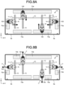
- FIGS. 8A and 8B are schematic diagrams illustrating multi-tier storage and transport of items stored in the multi-tier storage.
- a transport unit 10 is disposed inside the item take-out apparatus 1.
- the transport unit 10 includes a picker 14 and a plurality of rails 11 to 13.
- the picker 14 serves as a holding unit that extracts an item from a storage unit 70, and holds and transports the item.
- the picker 14 performs extraction of an item from a storage unit 70 (70a, 70b), and transport and placement of the extracted item to a take-out port 2.
- the picker 14 rotates at least in an XY plane.
- the picker moves forward and backward, leftward and rightward, and upward and downward, along the plurality of rails 11 to 13.
- the transport unit 10 includes the picker 14 that extracts an item from the storage unit 70 and holds the item, a rotation unit that rotates the picker 14, and a movement unit that moves the picker 14, which will be described in detail later.
- the storage units 70a are disposed on the four side surfaces inside the apparatus. Meanwhile, as shown in FIG. 8B , in the tier having the take-out ports 2, the storage units 70b are disposed avoiding areas including the take-out ports 2.
- the item take-out apparatus 1 moves the picker 14 by using the rails 11 to 13 to extract an item 100 from the storage unit 70a on each side surface, as shown in FIG. 8A .
- the item take-out apparatus 1 moves the picker 14 to transport an item 100 to the take-out port 2 in each side surface, as shown in FIG. 8B .
- pickers 14 and rails 13 corresponding to each of the four side surfaces are disposed inside the apparatus.
- the item take-out apparatus 1 may perform extraction of an item 100 from each storage unit 70, and placement of the item 100 on a take-out port 2.
- a multi-tier storage unit 70 is formed inside the apparatus by the storage units 70a in the tier having no take-out ports 2 shown in FIG. 8A and the storage units 70b in the tier having the take-out ports 2 shown in FIG. 8B .
- FIG. 9 illustrates a storage method of items 100 in the storage unit 70.
- the storage unit 70a shown in a lower part of FIG. 9 corresponds to FIG. 8A
- the storage unit 70b shown in an upper part of FIG. 9 corresponds to FIG. 8B .
- Coordinate axes in FIG. 9 and subsequent figures indicate that the figures show the storage units 70 on the back surface side that is the X-axis positive direction side.
- the figures show the storage unit 70 on the back side of the apparatus as viewed from the clerk who opened the doors 5, among the storage units 70 shown in FIGS. 8A and 8B .
- the figures show the storage unit 70 on the back side of the apparatus as viewed from the clerk who opened the doors 5, among the storage units 70 shown in FIGS. 8A and 8B .
- storage, extraction, transport, and placement of items 100 are similarly performed.
- the storage unit 70 has a plurality of partition members 81 to 83.
- a plurality of items 100 are vertically stacked and stored between the adjacent partition members 81.
- Each partition member 81 includes a main body part 81b that separates the items 100.
- a support member 81c is disposed at the bottom of the main body part 81b. The support member 81c supports from below the items 100 stacked between adjacent main body parts 81b.
- a lowermost item 100 among the plurality of vertically stacked items 100 is supported by the support members 81c at portions of a lower surface thereof from both outer sides in the Y-axis direction. A center portion of the lower surface of the lowermost item 100 is exposed over the entire surface in the X-axis direction between the support members 81c on both outer sides (see FIG. 10A ).
- a holding member 81a is disposed on the front surface of the main body part 81b of each partition member 81.
- the holding member 81a holds the second item 100 from the bottom and other items 100 stacked on the second item 100, among the plurality of stacked items 100.
- the second item 100 and items 100 on and above the second item 100 are held from the front (from the X-axis negative direction side corresponding to the front side in FIG. 9 ).
- the holding member 81a holds portions of the front surface (the side surface in the X-axis negative direction) of each item 100 from both outer sides in the Y-axis direction, so that a center portion of the front surface of each item 100 is exposed between the holding members 81a on both outer sides.
- the entire front surface of the lowermost item 100 is exposed so that the picker 14 can extract it forward.
- Each item 100 is stored in the storage unit 70 such that information indicating the kind of the item 100, such as the item name, printed on the front side surface, is exposed between the holding members 81a.
- the item take-out apparatus 1 may include a camera mounted on the picker 14, and may capture an image of the items 100 in the storage unit 70 with the camera while moving the picker 14.
- the item take-out apparatus 1 may analyze the image captured by the camera to confirm that the item being extracted from the storage unit 70 is the item designated by the user.
- the item take-out apparatus 1 may manage the kinds and the number of the items 100 being stored in the storage unit 70. That is, based on the image taken by the camera mounted on the picker 14, the item take-out apparatus 1 can specify the kinds and the number of the items 100 stored in the storage unit 70, confirm an item 100 to be taken out from the apparatus, and manage the inventory of the items 100.
- partition members 82, 83 different from the partition members 81 are used to avoid the take-out port 2, but the function of the partition members 82, 83 is the same as that of the partition members 81.
- the partition members 82, 83 also support portions of the lower surface of the lowermost item 100 among the plurality of stacked items 100, and also hold portions of the front surfaces of the items 100 from the uppermost one to the second one from the bottom.
- An item 100 is stored in the storage unit 70a through a gap between an upper end of the storage unit 70a and a lower end of the upper-tier storage unit 70b disposed above the storage unit 70a, as indicated by an arrow 400 in FIG. 9 . Also, in a storage unit 70 in another tier, an item 100 is stored through a gap between this storage unit 70 and an upper-tier storage unit 70.
- the storage unit 70 has, at an upper surface thereof, a storage port for storing an item 100 from above. Also, the storage unit 70 has, at a lower end thereof, an extraction port for extracting the lowermost item 100 laterally (in the X-axis negative direction corresponding to the front side in FIG. 9 ). In the storage unit 70, a plurality of items 100 stored from the storage port are stacked in the up-down direction. In the storage unit 70, the items 100 are stored such that only the lowermost item 100 among the plurality of items 100 can be extracted from the extraction port.
- a back member 81d connecting adjacent partition members 81 is disposed on the back surface side (X-axis positive direction side) of the items 100 stacked in the storage unit 70.
- a cutout part 81f is formed by cutting a portion of the back member 81d from the bottom surface side.
- the cutout part 81f is formed to have a height being a dimension from the lower surface of the support member 81c to the lower end of the holding member 81a.
- the cutout part 81f is formed to have a width being a dimension of a gap between the support members 81c. At least a portion of the back surface of each item 100 stored in the storage unit 70 is held by the back member 81d so as not to fall to the back side.
- the storage unit 70 in each tier shown in FIG. 9 is realized by arranging a plurality of storage containers 80 in the Y-axis direction, for example.
- FIGS. 10A and 10B show an example of a storage container 80.
- FIG. 10A shows the storage container 80 containing items 100
- FIG. 10B shows the storage container 80 in the empty state, i.e., containing no items 100.
- the storage container 80 is used while being fixed to a plurality of members 6 that are fixed to the inner wall of the housing and extend inside the item take-out apparatus 1.
- two holding members 181a shown in FIGS. 10A and 10B form a holding member 81a shown in FIG. 9 .
- the side plates 181b of the two closely contacting storage containers 80 form a main body part 81b shown in FIG. 9
- the support members 181c of the two closely contacting storage containers 80 form a support member 81c shown in FIG. 9 .
- an item 100 stored at the bottom is exposed, from the storage container 80, at the entire front surface (the side surface in the X-axis negative direction) and at front-side portions of the left and right side surfaces (in the Y axis direction).
- the lowermost item 100 is exposed at a center portion, in the width direction (Y axis direction), of the lower surface, over the entire lower surface in the X-axis direction, from a gap 81e between the support members 181c on both outer sides in the left-right direction.
- the cutout part 81f is formed at the lower end of the back member 81d as shown in FIG. 10B . Therefore, this item 100 is also exposed at a center portion, in the width direction, of the back surface from the cutout part 81f of the back member 81d.
- the item 100 stored at the bottom of the storage container 80 i.e., the lowermost item 100 in the storage unit 70
- a hook-shaped member may be inserted to the back surface side (X-axis positive direction) of the lowermost item 100. Then, the hook-shaped member is caught on the back surface of the item 100 and pulled forward, whereby the item 100 can be extracted forward from the storage unit 70.
- the transport unit 10 extracts the item 100 from the storage container 80, i.e., the storage unit 70, as described above, which will be described in detail later.
- the configuration of the storage unit 70 shown in FIG. 9 is an example, and the storage unit 70 may not necessarily be configured by closely connecting the storage containers 80 shown in FIGS. 10A and 10B .
- the storage containers 80 may be disposed away from each other in the Y axis direction.
- the storage method for items 100 is not limited to the method of stacking the items 100 in the up-down direction in the storage unit 70.
- the storage container 80 shown in FIGS. 10A and 10B may be rotated 90° around the X-axis direction, and the items 100 in the storage unit 70 may be stored while being arranged in the lateral direction (Y-axis direction).
- FIG. 11A and 11B show other examples of the storage method for items 100.
- the storage unit 70 may be partitioned into a plurality of storage spaces by partition members 84, and an item 100 may be stored in each storage space.
- the storage unit 70 may have a plurality of arms 85 for hanging items 100, and a plurality of items 100 may be stored while being hung and arranged in the front-rear direction (X-axis direction) by inserting the arms 85 through hanging holes of the items 100.
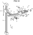
- FIG. 12 shows an example of the transport unit 10.
- the transport unit 10 includes a plurality of rails 11 to 13, and a picker 14.
- the transport unit 10 includes a plurality of driving units, and the control unit 20 controls driving of each driving unit to realize an operation of the transport unit 10 described below.
- the first rail 11 includes a rail part 11a extending in the up-down direction (Z-axis direction). As shown in FIG. 8 , the first rail 11 is fixed to the inside of the item take-out apparatus 1.
- the second rail 12 includes a main body part 12a, and a rail part 12b fixed to a side surface of the main body part 12a extends in the left-right direction (Y-axis direction).
- the rail part 11a of the first rail 11 is inserted through the main body part 12a.
- the second rail 12 is movable in the up-down direction along the rail part 11a as indicated by an arrow 401 in FIG. 12 .
- the third rail 13 includes a main body part 13a, and a rail part 13b fixed to an upper surface of the main body part 13a extends in the front-rear direction (X-axis direction).
- the rail part 12b of the second rail 12 is inserted through the main body part 13a.
- the third rail 13 is movable in the left-right direction (Y-axis direction) along the rail part 12b as indicated by an arrow 402.
- the picker 14 includes a base part 14a, a main body part 14b, and a plurality of finger parts 14f.
- the base part 14a mounted on the rail part 13b of the third rail 13 is movable in the front-rear direction (X-axis direction) along the rail part 13b as indicated by an arrow 403.
- the base part 14a is movable in the X-axis negative direction and in the X-axis positive direction with respect to the main body part 13a of the third rail 13.
- the base part 14a is rotatable around a shaft 14c as indicated by an arrow 404.
- connection part 14d rotatable as indicated by an arrow 405 is mounted on the base part 14a, and the connection part 14d is connected to the main body part 14b by a shaft 14e. This allows the main body part 14b to rotate with respect to the base part 14a as indicated by the arrow 405.
- the main body part 14b is pivotable around the shaft 14e as indicated by an arrow 406.
- the main body part 14b has a plurality of finger parts 14f which grasp and release an item 100.
- FIG. 13 illustrates a method of moving an item 100 by the picker 14.
- the lowermost item 100 stored in the storage unit 70 is exposed at the front-side portions of the left and right side surfaces, as viewed from the picker 14.
- the transport unit 10 can extract the item 100 from the storage unit 70 by grasping the exposed portions from the left and right outer sides with the finger parts 14f of the picker 14, and pulling the item 100 forward.
- the transport unit 10 can move the picker 14 forward and backward, leftward and rightward, and upward and downward inside the item take-out apparatus 1.
- the transport unit 10 moves the picker 14 grasping the item 100 to a take-out port 2, and causes the picker 14 to release the item 100.
- the user can take out the item 100 from the take-out port 2.
- a placement part 22 (22a, 22b) of the take-out port 2 may be provided with a guard 22b that prevents an item 100 from falling from a placement surface 22a into inside the apparatus.
- the method of placing an item 100 on the placement surface 22a is not limited to the method in which the picker 14 enters a space above the placement surface 22a, and releases the item 100 to place it on the placement surface 22a.
- a groove that allows the finger parts 14f of the picker 14 to pass may be formed in the placement surface 22a.
- the main body part 14b of the picker 14 may enter a space beneath the placement surface 22a such that the finger parts 14f pass the groove, and place the item 100 on the placement surface 22a.
- FIGS. 14A to 14C illustrate a method of placing an item 100 on a placement part 23 of a take-out port 2.
- a box-like placement part 23 has an upper surface and one side surface that are open.
- a groove 23b is formed to allow the finger parts 14f of the picker 14 to pass.
- the placement part 23 is fixed to the upper surface inside the housing of the item take-out apparatus 1.
- a take-out port 2 is disposed facing the opened upper surface of the placement part 23, and an item 100 can be taken out from the placement part 23 with the shutter of the take-out port 2 being manually or automatically opened.
- FIG. 14A a box-like placement part 23 has an upper surface and one side surface that are open.
- a groove 23b is formed to allow the finger parts 14f of the picker 14 to pass.
- the placement part 23 is fixed to the upper surface inside the housing of the item take-out apparatus 1.
- a take-out port 2 is disposed facing the opened upper surface of the placement part 23, and an item 100 can be taken out from the
- the transport unit 10 causes the main body part 14b of the picker 14 to enter a space beneath the placement part 23 such that the finger parts 14f grasping the item 100 are turned upward and pass the groove 23b. After the item 100 grasped by the finger parts 14f has been moved onto the placement surface 23a, the finger parts 14f releases the item 100 and the transport unit 10 moves the finger parts 14f downward and outward from the placement part 23 to complete placement of the item 100 on the placement surface 23a.
- FIG. 15 shows an example of a take-out port 2 disposed in the lower surface inside the housing of the item take-out apparatus 1.
- the transport unit 10 places an item 100 on the lower surface inside the housing as shown in FIG. 15 .
- the user inserts a hand into the item take-out apparatus 1 and takes out the item 100 via the take-out port 2 as shown by an arrow in FIG. 15 .
- the transport unit 10 is not limited to one having the robot hand type picker 14 shown in FIG. 12 .
- FIG. 16 shows another example of a picker 114.
- the transport unit 10 may have a tray-shaped picker 114.
- the transport unit 10 can move the picker 114 forward and backward, leftward and rightward, and upward and downward inside the item take-out apparatus 1 by using the plurality of rails 11 to 13 described in FIG. 12 .
- the transport unit 10 can rotate the picker 14 with respect to the third rail 13.
- the picker 114 has a tray shape composed of thin plates that are a bottom plate 114a, a back plate 114c, and two side plates 114b. An upper surface and one side surface of the picker 114 are open.
- the picker 114 has, at the open side surface, a hook 114d projecting from an upper surface of the bottom plate 114a.
- Each of the two side plates 114b has the same height as the back plate 114c on the back plate 114c side, but a part thereof on the hook 114d side is sloped such that the height is reduced as approaching the hook 114d.
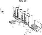
- FIG. 17 illustrates a method of moving an item 100 by the picker 114 shown in FIG. 16 .
- the lowermost item 100 stored in the storage unit 70 is exposed at a portion of the bottom surface and a portion of the back surface.
- the transport unit 10 can extract the item 100 from the storage unit 70 by hanging the hook 114d of the picker 14 on the back surface of the item 100, and pulling the item 100 forward.
- the transport unit 10 can move the picker 14 forward and backward, leftward and rightward, and upward and downward inside the item take-out apparatus 1.
- the transport unit 10 causes the bottom plate 114a of the picker 114 on which the item 100 is placed to enter a space beneath the placement part 32 such that the side plates 114b and the hook 114d pass grooves 32b and a groove 32c, thereby placing the item 100 on a placement surface 32a.
- the above method will be specifically described with reference to FIG. 18 to FIG. 21 .
- FIGS. 18A to 18D show the picker 114 that extracts an item 100a from a storage unit 70, as viewed from above.
- FIGS. 19A to 19D show the picker 114 that extracts the item 100a from the storage unit 70, as viewed from a side.
- FIGS. 19A to 19D show the side views of the picker 114 shown in FIGS. 18A to 18D , respectively.
- a dimension w1 between the side plates 114b of the picker 114 is greater than a dimension w2 between the outer sides of two adjacent support members 81c in the storage unit 70 (w1>w2).
- the picker 114 enters the storage unit 70 with the bottom plate 114a and the hook 114d being lower than the support members 81c of the storage unit 70, and moves upward.
- the picker 114 moves upward to a position where a part of the hook 114d exceeds the upper surfaces of the support members 81c, and then starts to move backward. With the two side plates 114b being outside the two adjacent support members 81c, the picker 114 moves backward such that the hook 114d passes the gap 81e between the support members 81c.
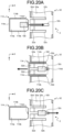
- FIGS. 20A to 20C show the picker 114 that places an item 100 on the placement part 32 of the take-out port 2, as viewed from above.
- FIGS. 21A to 21C show the picker 114 that places the item 100 on the placement part 32 of the take-out port 2, as viewed from a side.
- FIGS. 21A to 21C show the side views of the picker 114 shown in FIGS. 20A to 20C , respectively.
- two grooves 32b corresponding to the two side plates 114b of the picker 114 and a groove 32c corresponding to the hook 114d are formed in the placement part 32.
- the picker 114 With the bottom plate 114a being lower the placement part 32, the picker 114 enters the placement part 32 as indicated by arrows in FIG. 20A and FIG. 21A such that the side plates 114b pass the grooves 32b and the hook 114d passes the groove 32c, and thereafter, moves downward to a position where the hook 114d is beneath and outside the placement part 32.
- the item 100 on the bottom plate 114a of the picker 114 is transferred onto the placement surface 32a when the picker 114 enters the placement part 32.
- a slope area 32d whose thickness is reduced with distance from the take-out port 2 is preferably formed between the three grooves 32b and 32c of the placement part 32 as shown in FIG. 20A and FIG. 21A .
- the picker 114 having transferred the item 100 onto the placement surface 32a and moved downward, moves backward to a position away from the placement part 32 as shown in FIG. 20C and FIG. 21C .
- the user can take out the item 100 from the take-out port 2 as indicated by arrows in FIG. 20C and FIG. 21C .
- FIG. 17 and FIGS. 20A to 20C show the example in which the grooves 32b corresponding to the side plates 114b of the picker 114 are formed in the placement part 32, but the configuration of the placement part 32 is not limited thereto.
- FIG. 22 shows another example of the placement part 32. As shown in FIG. 22 , only a groove 32c corresponding to the hook 114d of the picker 114 may be formed in the placement part 32, and each of the side plates 114b of the picker 114 may pass a gap between the placement part 32 and the storage unit 70 adjacent to the placement part 32.
- the picker 14, 114 is moved by using the plurality of rails 11 to 13.
- the method of moving the picker 14, 114 is not particularly limited.
- the picker 14, 114 may be disposed at a distal end of a robot arm having a plurality of joints, and moved by the robot arm.
- the robot arm is installed inside the item take-out apparatus 1 such that the picker 14, 114 reaches all the items 100 in the storage units 70 and all the take-out ports 2, whereby the item take-out apparatus 1 can perform the above-described operations.
- the rectangular parallelepiped items 100 are schematically shown, but the shapes and the kinds of the items 100 are not particularly limited.
- an item may be stored in a box-shaped case and the case may be treated similarly to the item 100, whereby various items can be taken out by using the item take-out apparatus 1.
- the item take-out apparatus 1 may not necessarily realize all the take-out methods, and may realize some of the take-out methods according to the usage method of the item take-out apparatus 1 in the store.
- the item take-out apparatus can store a plurality of kinds of items in a storage unit in the apparatus, and can transport an item designated by a user to a take-out port.
- the item take-out apparatus has a plurality of take-out ports, and can transport an item to a take-out port designated by the user, for example. This allows the user to take out a desired item from a desired take-out port.
- the item take-out apparatus can transport an item to different take-out ports according to the kind of the item.
- the item take-out apparatus can transport an item to different take-out ports according to the position of an operation terminal on which an operation of designating the item has been performed.
- the item take-out apparatus can deal with various styles of selling items in stores.
Landscapes
- Physics & Mathematics (AREA)
- General Physics & Mathematics (AREA)
- Cash Registers Or Receiving Machines (AREA)
- Vending Machines For Individual Products (AREA)
- Control Of Vending Devices And Auxiliary Devices For Vending Devices (AREA)
Abstract
Description
- The present disclosure relates to an item take-out apparatus and an item take-out system that allow a user to take out an item stored in the apparatus to the outside of the apparatus.
- Conventionally, a variety of apparatus that enable a user to select an item from among a plurality of kinds of items stored in the apparatus and take out the selected item to the outside of the apparatus, have been used. For example,
PATENT LITERATURE 1 discloses a vending machine that stores items in a plurality of storage racks, and takes out by an arm, from a storage rack, an item selected by a user and discharges the item to the outside of the machine through an item pick-up port. - [PTL 1]
Japanese Laid-Open Patent Publication No. 2009-266162 - In the conventional art described above, for example, the apparatus is installed on a counter of a store with the item pick-up port facing a customer. When a clerk faces the customer across the counter, the clerk present on the back side of the apparatus cannot take out an item from the item pick-up port on the front side of the apparatus.
- The present disclosure is made in view of the conventional art including the above problem, and one object of the present disclosure is to provide an item take-out apparatus and an item take-out system capable of dealing with various styles of selling items in stores.
- An item take-out apparatus according to the present disclosure is an apparatus from which a user takes out an item. The apparatus includes: a storage unit configured to store items therein; a plurality of take-out ports through which the user takes out an item from inside the item take-out apparatus; and a transport unit configured to extract an item from the storage unit and transport the item to any of the plurality of take-out ports. The transport unit may transport an item designated by the user to a take-out port, through which the user takes out the item, among the plurality of take-out ports. The user includes a clerk and a customer, for example.
- In the above configuration, at least one take-out port may be disposed in each of a plurality of surfaces of a housing of the item take-out apparatus.
- In the above configuration, at least one take-out port may be disposed in each of at least two surfaces out of four side surfaces, an upper surface and a lower surface that constitute a housing of the item take-out apparatus.
- In the above configuration, at least one of the plurality of take-out ports may be disposed in an exterior wall of a store so that the user takes out the item from outside the store.
- In the above configuration, the apparatus may further include an operation unit for the user to designate an item and/or a take-out port.
- In the above configuration, the apparatus may further include a communication unit configured to receive information indicating the item and the take-out port designated by the user from an external apparatus including an operation unit for the user to designate an item and a take-out port.
- In the above configuration, when an item and a take-out port have been designated by using the operation unit, the transport unit may transport the designated item to the designated take-out port.
- In the above configuration, the apparatus may further include a memory that stores information indicating correspondence between kinds of the items and the plurality of take-out ports. When an item has been designated by using the operation unit, a take-out port corresponding to the item may be specified based on the information stored in the memory and the transport unit may transport the item to a take-out port corresponding to the item.
- In the above configuration, the apparatus may further include: a plurality of operation units; and a memory that stores information indicating correspondence between the respective operation units and the plurality of take-out ports. When an item has been designated by using any one of the operation units, a take-out port corresponding to the operation unit is specified based on the information stored in the memory and the transport unit may transport the item to a take-out port corresponding to the operation unit.
- In the above configuration, when an item for which purchase eligibility is required has been designated by using the operation unit, the transport unit may transport the item to the take-out port on condition that it has been confirmed that a customer who purchases the item has the purchase eligibility.
- In the above configuration, the transport unit may transport the item to the take-out port on condition that information indicating that the customer has the purchase eligibility has been inputted by using the operation unit.
- In the above configuration, the apparatus may further include a reading device configured to read eligibility information on the purchase eligibility from a medium storing the eligibility information. The transport unit may transport the item to the take-out port on condition that the reading device has read the eligibility information from a medium owned by the customer.
- In the above configuration, the apparatus may further include a communication unit configured to receive, from an external apparatus that reads eligibility information on the purchase eligibility from a medium storing the eligibility information, information indicating whether or not the eligibility information has been read from the medium. The transport unit may transport the item to the take-out port on condition that the communication unit has received information indicating that the eligibility information has been read from a medium owned by the customer.
- In the above configuration, the storage unit may have a storage port and an extraction port, and store therein items received from the storage port in such a manner that only one item, among a plurality of items being stored therein, is extracted from the extraction port to outside the storage unit. The transport unit may transport the one item extracted from the extraction port, to the take-out port.
- In the above configuration, the transport unit may further include: a holding unit configured to extract an item from the extraction port of the storage unit; a rotation unit configured to rotate the holding unit; and a movement unit configured to move the holding unit.
- In the above configuration, the holding unit may include: a tray on which the item can be placed; and a hook projecting upward from the tray. The storage unit may store therein a plurality of items by stacking the items in an up-down direction in such a manner that entire side surface of the lowermost item is exposed from the storage unit in a direction for extracting the lowermost item while exposing a portion of a lower surface and a portion of a back surface of the lowermost item from the storage unit. The transport unit may extract the lowermost item from the storage unit with the hook of the holding unit being caught on the back surface of the lowermost item, and place the extracted item on the tray to transport the item.
- In the above configuration, the take-out port may further include a placement part on which an item to be taken out from the take-out port is placed, and a groove may be formed in the placement part. The transport unit may cause the tray to enter a space beneath the placement part such that the item on the tray is transferred onto the placement part while the hook passes into the groove, move downward to a position where the hook is separated from the item placed on the placement part and move backward, to transport the item to the take-out port.
- An item take-out system according to the present disclosure is a system from which a user takes out an item. The system includes: a storage unit configured to store items therein; a plurality of take-out ports through which the user takes out an item from inside the item take-out apparatus; and a transport unit configured to extract an item from the storage unit and transport the item to any of the plurality of take-out ports. The transport unit may transport an item designated by the user to a take-out port, through which the user takes out the item, among the plurality of take-out ports. The user includes a clerk and a customer, for example.
- According to the present disclosure, the item take-out apparatus can deal with various styles of selling items in stores.
-
- [
FIG. 1] FIG. 1 is a schematic diagram illustrating an outline of an item take-out apparatus according to an embodiment of the present disclosure. - [
FIG. 2] FIG. 2 is a schematic diagram illustrating examples of the item take-out apparatus. - [
FIG. 3] FIG. 3 is a block diagram schematically showing the configuration of the item take-out apparatus. - [
FIG. 4] FIG. 4 is a schematic diagram illustrating an example of the item take-out apparatus used in a store. - [
FIG. 5] FIG. 5 is a schematic diagram illustrating an example of the item take-out apparatus having take-out ports inside and outside a store. - [
FIG. 6] FIG. 6 is a schematic diagram illustrating an example of the item take-out apparatus having take-out ports outside a store. - [
FIG. 7] FIG. 7 illustrates storage units of the item take-out apparatus. - [
FIGS. 8A and 8B] FIGS. 8A and 8B are schematic diagrams illustrating multi-tier storage and transport of items. - [FIGS. 9A and 9B] FIGS. 9A and 9B illustrate methods of storing items in a storage unit.
- [
FIGS. 10A and 10B] FIGS. 10A and 10B show an example of a storage container. - [
FIGS. 11A and 11B] FIGS. 11A and 11B show other examples of the item storage method. - [
FIG. 12] FIG. 12 shows an example of a transport unit. - [
FIG. 13] FIG. 13 illustrates a method of moving an item by a picker. - [
FIGS. 14A to 14C] FIGS. 14A to 14C illustrate a method of placing an item on a placement part of a take-out port. - [
FIG. 15] FIG. 15 shows an example of a take-out port disposed in a lower surface inside a housing of the item take-out apparatus. - [
FIG. 16] FIG. 16 shows another example of the picker. - [
FIG. 17] FIG. 17 illustrates a method of moving an item by the picker shown inFIG. 16 . - [
FIGS. 18A to 18D] FIGS. 18A to 18D show the picker that extracts an item from a storage unit, as viewed from above. - [
FIGS. 19A to 19D] FIGS. 19A to 19C show the picker that extracts the item from the storage unit, as viewed from a side. - [
FIGS. 20A to 20C] FIGS. 20A to 20C show the picker that places an item on a placement part of a take-out port, as viewed from above. - [
FIGS. 21A to 21C] FIGS. 21A to 21C show the picker that places the item on the placement part of the take-out port, as viewed from a side. - [
FIG. 22] FIG. 22 shows another example of the placement part. - Hereinafter, an embodiment of an item take-out apparatus and an item take-out system according to the present disclosure will be described with reference to the drawings.
FIG. 1 is a schematic diagram illustrating an outline of an item take-outapparatus 1 according to the present embodiment. The item take-outapparatus 1 is installed in a store in which items are sold, and is used by a clerk or a customer (hereinafter referred to as "user") to take out an item that the customer purchases. Coordinate axes in the drawings showing the configuration of the item take-outapparatus 1 of the present embodiment indicate the relationship of the components of the item take-outapparatus 1 shown in each drawing. A Z-axis direction corresponds to an up-down direction, and an XY plane corresponds to a horizontal plane. The directions shown in each drawing are examples and do not limit the installation method for the respective components and the directions of the components during operations. - A plurality of kinds of items are stored in the item take-out
apparatus 1. The item take-outapparatus 1 is provided with a plurality of take-outports 2 for the user to take out items from the item take-outapparatus 1.FIG. 1 shows an example of take-outports 2 of the item take-outapparatus 1. - A take-out
port 2 is disposed in at least one surface out of six surfaces including four side surfaces (i.e., a front surface, a back surface, a left-side surface, and a right-side surface), an upper surface, and a lower surface of the item take-outapparatus 1. Take-out ports 2 may be disposed in a plurality of surfaces constituting a housing of the item take-outapparatus 1. One or a plurality of take-outports 2 are disposed in one surface. A plurality of take-outports 2 may allow the user to take out an item from the item take-outapparatus 1 in a plurality of different directions. A surface in which the take-outport 2 is formed is not particularly limited. Also, the positions and the number of the take-outports 2 in each surface are not particularly limited. The take-outports 2 are disposed in the item take-outapparatus 1 according to the usage method of the item take-outapparatus 1 in the store. - As shown in
FIG. 1 , the item take-outapparatus 1 can receive an input of information designating an item, and an input of information designating a take-outport 2 from which the designated item is taken out from the apparatus (A1). The information inputting method is not limited. For example, the item take-outapparatus 1 may include an operation unit by which the user performs the designation, and the designation information may be inputted to the item take-outapparatus 1 from the operation unit. For example, the user may operate an operation unit included in an external apparatus such as an operation terminal or a cash register to perform the designation, and the designation information is inputted to the item take-outapparatus 1 from the external device. - Based on the inputted information, the item take-out
apparatus 1 transports the item designated from among the items stored in the apparatus, to the designated take-out port 2 (A2). Thus, the user can take out the desired item from the desired take-out port 2 (A3). - Each take-out
port 2 may be always opened, or may be opened and closed by a shutter. The shutter may be slidably moved to open and close the take-outport 2. The shutter may be pivoted inward and/or outward with respect to the take-outport 2 to open and close the take-outport 2. The shutter may be manually opened and closed by the user. The shutter may be automatically opened and closed by the item take-outapparatus 1. For example, the shutters of the take-outports 2 may be usually closed, and after transporting the designateditem 100 to the designated take-outport 2, the item take-outapparatus 1 may automatically open the shutter of the take-outport 2 to which theitem 100 has been transported. In this case, for example, a sensor not shown inFIG. 1 may be disposed at the take-outport 2, and the item take-outapparatus 1 may automatically close the shutter upon detecting, by the sensor, that theitem 100 has been taken out from the take-outport 2. - The user may not necessarily designate both an item and a take-out
port 2, and may designate only an item. In this case, the item take-outapparatus 1 may automatically specifies a take-outport 2 corresponding to the designated item, and transport the designated item to the specified take-outport 2. - For example, information on correspondence between the kinds of items and the take-out
ports 2 may be prepared in advance, and a take-outport 2 may be specified according to an item designated by the user, based on the information. It may be set that an item, for which a customer is required to satisfy a specific condition such as an age restriction to purchase the item, is transported to a take-outport 2 facing aclerk 200. A plurality of operation units to be input sources of item designating information may be disposed, information indicating correspondence between the operation units and the take-outports 2 may be prepared in advance, and a take-outport 2 corresponding to an operation unit by which an item designating operation has been performed may be specified based on the information. The take-outport 2 may be specified by the item take-outapparatus 1, or may be specified by an external apparatus connected to the item take-outapparatus 1. - Although the counter-type item take-out
apparatus 1 is shown inFIG. 1 , the configuration of the item take-outapparatus 1 is not limited thereto. Although the item take-outapparatus 1 shown inFIG. 1 has a height that allows an external apparatus such as a cash register or an operation terminal to be disposed and used on the upper surface thereof, the height of the item take-outapparatus 1 is not particularly limited. Also, the dimensions of the item take-outapparatus 1 in the left-right direction and front-rear direction are not particularly limited. - The item take-out
apparatus 1 may not necessarily be installed on the floor.FIG. 2 is a schematic diagram illustrating examples of the item take-outapparatus 1.FIG. 2 shows a counter-type item take-outapparatus 1 installed on the floor, and a hanging-type item take-outapparatus 1 disposed at a position away from the floor. The hanging-type item take-outapparatus 1 may be hung from the ceiling of the store, or may be fixed to a wall surface of the store. - The
clerk 200 may serve acustomer 300 over the counter-type item take-outapparatus 1 and take out an item that thecustomer 300 purchases, from a take-outport 2 of the item take-outapparatus 1. The item take-outapparatus 1 may have a take-outport 2 in the side surface on thecustomer 300 side, and the customer may take out the item from the take-outport 2 by himself/herself. - Also, as shown in
FIG. 2 , theclerk 200 may take out anitem 100 that thecustomer 300 purchases, from a take-outport 2 of the hanging-type item take-outapparatus 1. The hanging-type item take-outapparatus 1 may have a take-outport 2 in the lower surface thereof, and theclerk 200 may take out theitem 100 from the lower surface of the item take-outapparatus 1. -
FIG. 3 is a block diagram schematically showing the configuration of the item take-outapparatus 1. The item take-outapparatus 1 includes atransport unit 10, acontrol unit 20, acommunication unit 30, and a memory 40. Thetransport unit 10 extracts an item from a storage unit inside the apparatus and transports the item to a take-outport 2, which will be described in detail later. - The memory 40 is a non-volatile storage apparatus. The memory 40 is used to store information necessary for operations of the item take-out
apparatus 1. For example, information indicating correspondence between a plurality of storage units inside the apparatus and the kinds of items stored in the respective storage units, is stored in the memory 40. For example, information indicating correspondence between a plurality of kinds of items and a plurality of take-outports 2 is stored in the memory 40. For example, information indicating correspondence between a plurality of operation units and a plurality of take-outports 2 is stored in the memory 40. The plurality of operation units may include an operation unit of an external apparatus. - The
communication unit 30 exchanges information with external apparatuses through wired communication or wireless communication. For example, an item take-out system includes the external apparatuses and the item take-outapparatus 1. Anoperation terminal 50 is an example of the external apparatuses. Thecommunication unit 30 can receive information indicating an item and a take-outport 2 designated by the user, from theoperation terminal 50 serving as an operation unit. For example, a tablet-type computer terminal including an operation unit and a display unit is used as theoperation terminal 50. For example, a cash register including an operation unit and a display unit is used as theoperation terminal 50. - Based on the information received by the
communication unit 30 and the information stored in the memory 40, thecontrol unit 20 specifies the position of a storage unit in which the item is stored and a take-outport 2 to be a destination of the item. Thecontrol unit 20 controls thetransport unit 10 to extract the item from the specified storage unit, and transport the item to the specified take-outport 2. Thecontrol unit 20 controlling the respective units based on the information inputted from outside and the information stored in the memory 40, realizes the functions and operations of the item take-outapparatus 1 described in the present embodiment. - As shown in
FIG. 3 , theoperation terminal 50 may be connected to apayment apparatus 60 that performs a payment process on an item price. For example, a cash register serving as thepayment apparatus 60 is connected to a computer terminal serving as theoperation terminal 50. For example, a money handling apparatus serving as thepayment apparatus 60 is connected to a cash register serving as theoperation terminal 50. - The
payment apparatus 60 is not limited to an apparatus performing a cash payment process, and may be an apparatus performing an electronic payment process, instead of or in addition to the cash payment process. For example, thepayment apparatus 60 may perform the item price payment process by an electronic payment using a debit card, a credit card, a prepaid card, electronic money, etc. - The item take-out
apparatus 1 may transport the item to the take-outport 2, on the condition that thepayment apparatus 60 has completed the item price payment process. For example, thepayment apparatus 60 inputs, to theoperation terminal 50, information indicating that the payment for purchasing an item has been completed, and theoperation terminal 50 inputs, to the item take-outapparatus 1, information designating the item that has been purchased. Then, the item take-outapparatus 1 transports the designated item to the take-outport 2. - At least one of the
operation terminal 50 and thepayment apparatus 60 may serve as a confirmation apparatus that confirms whether or not a customer has purchase eligibility for purchasing an item. The purchase eligibility is required for some items, and these items can be purchased only by customers having the purchase eligibility. In the memory 40, information indicating the kinds of items for which the purchase eligibility is required is stored in advance. Based on the information in the memory 40, the item take-outapparatus 1 determines whether or not the purchase eligibility is required for the item designated by using theoperation terminal 50. Upon detecting that the purchase eligibility is required for the designated item, the item take-outapparatus 1 performs a notification process for requesting confirmation of whether or not the customer has the purchase eligibility. For example, information instructing the operation for confirming the purchase eligibility of the customer is displayed on the display unit of theoperation terminal 50. - There are items, for which the age of purchasers is restricted, such as tobacco and alcoholic beverages. When such an item has been designated, the confirmation apparatus performs a confirmation process of confirming with a certificate that the age of the purchaser exceeds a predetermined age. A driver's license or the like issued by a public organization is used as the certificate.
- For example, the clerk recognizes that the confirmation process is required and then asks the customer purchasing the item, for which purchase eligibility is required, to present a certificate. The clerk visually checks the certificate and performs a predetermined operation by using the confirmation apparatus to complete the confirmation process.
- For example, the confirmation apparatus may include a reading device capable of reading information on the certificate. The customer uses the reading device to read the information on the certificate. Based on the information on the certificate read by the reading device, the confirmation apparatus determines whether or not the customer has the purchase eligibility for the item to complete the confirmation process. If the purchase eligibility is recorded on a card type medium such as a magnetic card or an IC card, the confirmation process is performed by using a reading device that reads information from the medium. If the purchase eligibility is to be confirmed by using a portable communication terminal such as a smartphone of the customer, the confirmation process is performed by using a reading device capable of obtaining information from the portable communication terminal.
- There are items, for which purchasers are restricted, such as pharmaceutical products that only persons having prescriptions can purchase. When such an item has been designated, the confirmation apparatus confirms that the customer has the purchase eligibility for the item, through the reading device or the visual check by the clerk as described above, to complete the confirmation process.
- The result of the confirmation process is inputted to the item take-out
apparatus 1 from the confirmation apparatus, i.e., at least one of theoperation terminal 50 and thepayment apparatus 60, having finished the confirmation process. The item take-outapparatus 1 transports the item to the take-outport 2 on the condition that it has been confirmed by using theoperation terminal 50 and/or thepayment apparatus 60 that the customer has the purchase eligibility for the item. - The item take-out
apparatus 1 may not necessarily detect an item for which purchase eligibility is required, and theoperation terminal 50 or thepayment apparatus 60 may start the confirmation process upon detecting an item for which purchase eligibility is required. In this case, for example, theoperation terminal 50 or thepayment apparatus 60 obtains the result of the confirmation process, and then theoperation terminal 50 inputs information designating the item to the item take-outapparatus 1. After receiving the information, the item take-outapparatus 1 can transport the designated item to the take-outport 2. - The configuration shown in
FIG. 3 is an example, and does not limit the configuration of the item take-outapparatus 1 and the apparatuses connected to and used with the item take-outapparatus 1. Distributed or integrated forms of each apparatus are not limited to the above example, and all or some of the forms may be distributed or integrated functionally or physically in any unit depending on various loads, use statuses, or the like. For example, the item take-outapparatus 1 may include an operation unit, and the item take-outapparatus 1 may realize the function of theoperation terminal 50 described in the present embodiment. For another example, theoperation terminal 50 may also serve as thepayment apparatus 60. - Next, usage examples of the item take-out
apparatus 1 will be described.FIG. 4 is a schematic diagram illustrating an example of the item take-outapparatus 1 used in the store. In the example shown inFIG. 4 , the item take-outapparatus 1 is installed at a checkout counter of the store, and is used with a plurality of operation terminals 50 (50a, 50b) and a plurality of payment apparatuses 60 (60a, 60b) connected to theapparatus 1. Theclerk 200 faces thecustomer 300 across the item take-outapparatus 1 that separates them. The item take-outapparatus 1 has a plurality of take-out ports 2 (2a, 2b). The take-outport 2a is disposed on the side surface of theclerk 200 side, and the take-outport 2b is disposed on the side surface of thecustomer 300 side. - The
clerk 200 serving thecustomer 300 operates theoperation terminal 50a installed on the item take-outapparatus 1 to designate an item that thecustomer 300 purchases. In addition, theclerk 200 performs a payment process for the price of the item that thecustomer 300 purchases, by using theoperation terminal 50a and thepayment apparatus 60a. For example, theclerk 200 deposits cash received from thecustomer 300 into thepayment apparatus 60a, and returns change dispensed from thepayment apparatus 60a to thecustomer 300 according to need. For example, according to a request of thecustomer 300, the item price payment process may be performed by electronic payment in thepayment apparatus 60. - If the
customer 300 desires to purchase an item for which purchase eligibility is required, a confirmation process for the purchase eligibility is performed. For example, theclerk 200 asks thecustomer 300 to present a certificate. In the confirmation process, theclerk 200 visually checks the certificate to confirm that thecustomer 300 has the purchase eligibility for the item. Alternatively, in the confirmation process, thecustomer 300 causes the reading device connected to theoperation terminal 50a or thepayment apparatus 60a to read information from the certificate, for example. After performing the confirmation process through the visual check or the reading device, the item can be taken out from the item take-outapparatus 1 on the condition that a confirmation result indicating that thecustomer 300 has the purchase eligibility has been obtained. - In the memory 40 of the item take-out
apparatus 1, storage information indicating correspondence between the kinds of items and their respective storage units inside the apparatus is stored in advance. Furthermore, take-out information in which theoperation terminal 50a is associated with the take-outport 2a and theoperation terminal 50b is associated with the take-outport 2b, is stored in the memory 40. Based on the storage information and the take-out information, thecontrol unit 20 of the item take-outapparatus 1 specifies the storage unit in which the item designated by using theoperation terminal 50a is stored, and specifies the take-outport 2a associated with theoperation terminal 50a. - The
control unit 20 controls thetransport unit 10 to extract the item from the specified storage unit, and transport the item to the take-outport 2a. Thecontrol unit 20 performs a notification process for notifying theclerk 200 that the item has been transported to the take-outport 2a. In the notification process, for example, information indicating that the item can be taken out from the take-outport 2a is displayed on the display unit of theoperation terminal 50a. Upon checking the display, theclerk 200 takes out theitem 100 from the take-outport 2a and passes theitem 100 to thecustomer 300 as shown inFIG. 4 to complete the transaction. - A self-transaction, in which a
customer 301 purchases an item by himself/herself without being served by theclerk 200, may also be performed. As shown inFIG. 4 , apayment apparatus 60b is installed in the counter. An inlet/outlet 61 of thepayment apparatus 60b is disposed on the side surface, of the counter, including the take-outport 2b for self-transaction. Thecustomer 301 can deposit banknotes and coins to be paid for the item, from the inlet/outlet 61, into thepayment apparatus 60b. Thecustomer 301 can receive banknotes and coins dispensed as change from the inlet/outlet 61 of thepayment apparatus 60b. - The
customer 301 selects an item by operating theoperation terminal 50b, and performs a payment process for the price of the item by using thepayment apparatus 60b. For example, thecustomer 301 deposits cash to be paid for purchasing the item into thepayment apparatus 60b, and receives change dispensed from thepayment apparatus 60b. For example, thecustomer 301 operates theoperation terminal 50b to pay for the item by electronic payment. - When the
customer 301 has operated theoperation terminal 50b and selected an item for which purchase eligibility is required, theoperation terminal 50b starts a confirmation process for the purchase eligibility. The confirmation process is performed by thecustomer 300 by causing the reading device of theoperation terminal 50b to read information from a certificate of the customer. Only when the confirmation result of the confirmation process indicates that thecustomer 301 has the purchase eligibility, thecustomer 301 is allowed to take out the item from the item take-outapparatus 1. - With reference to the storage information and the take-out information stored in the memory 40, the
control unit 20 of the item take-outapparatus 1 specifies the storage unit in which the item designated by thecustomer 301 through theoperation terminal 50b is stored, and specifies the take-outport 2b associated with theoperation terminal 50b. Thecontrol unit 20 controls thetransport unit 10 to extract the item from the specified storage unit, and transport the item to the take-outport 2b. Thecontrol unit 20 displays information indicating that the item can be taken out from the take-outport 2b, on the display unit of theoperation terminal 50b to notify thecustomer 301 of this fact. Upon checking the information on the display, thecustomer 301 takes out the item from the take-outport 2b to complete the transaction. - A semi-self-transaction, in which the
clerk 200 serving a customer performs an item designating operation and an item price payment process, and the customer takes out the item from the take-outport 2, may also be performed. In this case, theclerk 200 performs an operation of designating an item that the customer purchases and a payment for the price of the item by using theoperation terminal 50a and thepayment apparatus 60a. Theclerk 200 operates theoperation terminal 50a to perform an operation of designating the take-outport 2b as a destination of the item. Thecontrol unit 20 of the item take-outapparatus 1 controls thetransport unit 10 to transport the item to the take-outport 2b, on the condition that the payment process has been completed in thepayment apparatus 60a. The customer takes out the item from the take-outport 2b to complete the transaction. - A semi-self-transaction, in which the
clerk 200 serving a customer performs an item designating operation, and the customer performs an item price payment process and takes out the item from the take-outport 2, may also be performed. In this case, theclerk 200 operates theoperation terminal 50a to designate an item that the customer purchases. Theclerk 200 performs a predetermined operation by using theoperation terminal 50a, whereby information indicating the price of the item is inputted to thepayment apparatus 60b, and the take-outport 2b is designated as a destination of the item. The customer performs a payment process by using thepayment apparatus 60b to pay for the item. Thecontrol unit 20 of the item take-outapparatus 1 controls thetransport unit 10 to transport the item to the take-outport 2b, on the condition that the payment process has been completed in thepayment apparatus 60b. The customer takes out the item from the take-outport 2b to complete the transaction. - A semi-self-transaction, in which a customer performs an item designating operation by himself/herself, and the
clerk 200 performs an item price payment process and passes the item to the customer, may also be performed. In this case, the customer designates an item by operating theoperation terminal 50b. When the customer performs a predetermined operation by using theoperation terminal 50b, information indicating the designated item is inputted to theoperation terminal 50a, and the take-outport 2a is designated as a destination of the item. Theclerk 200 performs an item price payment process for the item by using thepayment apparatus 60a based on the information received in theoperation terminal 50a. Thecontrol unit 20 of the item take-outapparatus 1 controls thetransport unit 10 to transport the item to the take-outport 2a, on the condition that the payment process has been completed in thepayment apparatus 60a. Theclerk 200 take outs the item from the take-outport 2a and passes the item to the customer to complete the transaction. -
FIG. 5 is a schematic diagram illustrating an example of the item take-outapparatus 1 having take-outports 2 inside and outside a store. InFIG. 5 , the apparatuses are viewed from above. For example, the item take-outapparatus 1 is installed in the store near anexterior wall 3 of the store, and the take-outport 2b is disposed in theexterior wall 3 so that a customer can take out an item from outside the store. Thepayment apparatus 60b is installed in the store near theexterior wall 3 of the store, and the inlet/outlet 61 is disposed on theexterior wall 3 so that the customer can deposit and receive cash from outside the store. Theoperation terminal 50b including the operation unit and the display unit is fixed to the exterior wall of the store so that the customer can operate it from outside the store. - The
clerk 200 can serve and deal with thecustomer 300 inside the store as described inFIG. 4 . Moreover, theclerk 200 can deal with thecustomer 301 outside the store. In this case, the semi-self-transaction, in which at least one of designation of an item, payment for the item price, and reception of the item is performed by thecustomer 301 outside the store, is performed in the same manner as described inFIG. 4 . Also, for example, thecustomer 301 outside the store can perform the self-transaction in the same manner as described inFIG. 4 , in which thecustomer 301 designates the item by using theoperation terminal 50b, pays for the item by using thepayment apparatus 60b and receives the item from the take-outport 2b. This allows thecustomer 301 to purchase the item even during outside business hours of the store. -
FIG. 6 is a schematic diagram illustrating an example of the item take-outapparatus 1 having take-outports 2 outside a store. The item take-outapparatus 1 is placed in the store near an exterior wall of the store, and a plurality of take-out ports 2 (2a, 2b) are disposed in exterior walls so that a customer can take out an item from outside the store. The take-outports 2 may be respectively disposed in different exterior walls of the store as shown inFIG. 6 , or a plurality of take-outports 2 may be disposed in the same exterior wall. Theoperation terminal 50b and thepayment apparatus 60b are installed so that the customer can perform the payment process and receive the item from outside the store in the same manner as in the case ofFIG. 5 . - A window 4 is formed in the wall of the store where the take-out
port 2a is disposed. Using the window 4, the clerk can serve the customer outside the store while being inside the store. For example, the clerk performs the semi-self-transaction described inFIG. 4 in which the clerk designates an item by using theoperation terminal 50a and handles the payment for the item by using thepayment apparatus 60a, and the customer receives the item from the take-outport 2a on the surface of the exterior wall of the store. For another example, the customer outside the store performs the self-transaction in the same manner as described inFIG. 4 , in which the customer designates an item by using theoperation terminal 50b, performs the payment for the item by using thepayment apparatus 60b and receives the item from the take-outport 2b. - The transaction methods described with reference to
FIG. 4 to FIG. 6 are examples, and the transaction methods using the item take-outapparatus 1 are not limited thereto. For example, only part of the above transaction methods may be performed by using the item take-outapparatus 1. For another example, a plurality of pairs of theoperation terminal 50a and thepayment apparatus 60a may be disposed so that a plurality of clerks can simultaneously serve customers. Likewise, a plurality of pairs of theoperation terminal 50b and thepayment apparatus 60b may be provided so that a plurality of customers can simultaneously perform self-transactions. Even in these cases, transactions may be performed by using theoperation terminals 50 and thepayment apparatuses 60 as described above. Three or more take-outports 2 may be disposed on the apparatus. For example, the kinds of items may be associated with the take-outports 2 in the take-out information stored in the memory 40, and the item take-outapparatus 1 may transport items to different take-outports 2 based on the kinds of the items. For example, the item take-outapparatus 1 may be composed of a combination of all or some of the components shown inFIGS. 4 to 6 . - Next, storage of items in the item take-out
apparatus 1 will be described.FIG. 7 illustratesstorage units 70 of the item take-outapparatus 1. As shown inFIG. 7 , one of the surfaces of the item take-outapparatus 1 is openable so that items can be stored in thestorage units 70 disposed inside the apparatus. -
FIG. 7 shows an example in which the item take-outapparatus 1 has double doors 5 (5a, 5b), separated roughly at the center, in a side surface of theapparatus 1 to be on the clerk side when the apparatus is installed on a counter of the store. When the doors 5 are pivoted and opened outwards, the inside of the apparatus is opened, so that the clerk can store items in thestorage units 70. - In the example shown in
FIG. 7 , thestorage units 70 are disposed on the inner sides of the double doors 5. Thestorage units 70 are also disposed on the opposed left and right side surfaces as viewed from the clerk who opened the doors 5, and the back surface, inside the apparatus. That is, thestorage units 70 are disposed on all the four side surfaces inside the apparatus. However, the side surfaces on which thestorage units 70 are to be disposed are not particularly limited. Thestorage units 70 may be disposed on some of the four side surfaces. Thestorage units 70 may also be disposed on at least one of the upper surface and the lower surface inside the apparatus. - For example, the
storage units 70 are arranged in a plurality of tiers in the up-down direction (Z-axis direction), so that a plurality of items can be stored in each tier.FIGS. 8A and 8B are schematic diagrams illustrating multi-tier storage and transport of items stored in the multi-tier storage. - As shown in
FIGS. 8A and 8B , atransport unit 10 is disposed inside the item take-outapparatus 1. Thetransport unit 10 includes apicker 14 and a plurality ofrails 11 to 13. Thepicker 14 serves as a holding unit that extracts an item from astorage unit 70, and holds and transports the item. Thepicker 14 performs extraction of an item from a storage unit 70 (70a, 70b), and transport and placement of the extracted item to a take-outport 2. Thepicker 14 rotates at least in an XY plane. The picker moves forward and backward, leftward and rightward, and upward and downward, along the plurality ofrails 11 to 13. Thetransport unit 10 includes thepicker 14 that extracts an item from thestorage unit 70 and holds the item, a rotation unit that rotates thepicker 14, and a movement unit that moves thepicker 14, which will be described in detail later. - As shown in
FIG. 8A , in the tier having no take-outports 2, thestorage units 70a are disposed on the four side surfaces inside the apparatus. Meanwhile, as shown inFIG. 8B , in the tier having the take-outports 2, thestorage units 70b are disposed avoiding areas including the take-outports 2. - The item take-out
apparatus 1 moves thepicker 14 by using therails 11 to 13 to extract anitem 100 from thestorage unit 70a on each side surface, as shown inFIG. 8A . The item take-outapparatus 1 moves thepicker 14 to transport anitem 100 to the take-outport 2 in each side surface, as shown inFIG. 8B . - In
FIGS. 8A and 8B ,pickers 14 and rails 13 corresponding to each of the four side surfaces are disposed inside the apparatus. However, by moving and rotating onepicker 14, the item take-outapparatus 1 may perform extraction of anitem 100 from eachstorage unit 70, and placement of theitem 100 on a take-outport 2. - A
multi-tier storage unit 70 is formed inside the apparatus by thestorage units 70a in the tier having no take-outports 2 shown inFIG. 8A and thestorage units 70b in the tier having the take-outports 2 shown inFIG. 8B .FIG. 9 illustrates a storage method ofitems 100 in thestorage unit 70. Thestorage unit 70a shown in a lower part ofFIG. 9 corresponds toFIG. 8A , and thestorage unit 70b shown in an upper part ofFIG. 9 corresponds toFIG. 8B . Coordinate axes inFIG. 9 and subsequent figures indicate that the figures show thestorage units 70 on the back surface side that is the X-axis positive direction side. That is, the figures show thestorage unit 70 on the back side of the apparatus as viewed from the clerk who opened the doors 5, among thestorage units 70 shown inFIGS. 8A and 8B . However, even in theother storage units 70, storage, extraction, transport, and placement ofitems 100 are similarly performed. - As shown in
FIG. 9 , the storage unit 70 (70a, 70b) has a plurality ofpartition members 81 to 83. As shown in the lower part ofFIG. 9 , in thestorage unit 70a, a plurality ofitems 100 are vertically stacked and stored between theadjacent partition members 81. Eachpartition member 81 includes amain body part 81b that separates theitems 100. Asupport member 81c is disposed at the bottom of themain body part 81b. Thesupport member 81c supports from below theitems 100 stacked between adjacentmain body parts 81b. Alowermost item 100 among the plurality of vertically stackeditems 100 is supported by thesupport members 81c at portions of a lower surface thereof from both outer sides in the Y-axis direction. A center portion of the lower surface of thelowermost item 100 is exposed over the entire surface in the X-axis direction between thesupport members 81c on both outer sides (seeFIG. 10A ). - A holding
member 81a is disposed on the front surface of themain body part 81b of eachpartition member 81. The holdingmember 81a holds thesecond item 100 from the bottom andother items 100 stacked on thesecond item 100, among the plurality ofstacked items 100. Thesecond item 100 anditems 100 on and above thesecond item 100 are held from the front (from the X-axis negative direction side corresponding to the front side inFIG. 9 ). The holdingmember 81a holds portions of the front surface (the side surface in the X-axis negative direction) of eachitem 100 from both outer sides in the Y-axis direction, so that a center portion of the front surface of eachitem 100 is exposed between the holdingmembers 81a on both outer sides. The entire front surface of thelowermost item 100 is exposed so that thepicker 14 can extract it forward. - Each
item 100 is stored in thestorage unit 70 such that information indicating the kind of theitem 100, such as the item name, printed on the front side surface, is exposed between the holdingmembers 81a. This allows the clerk to easily check the kinds of theitems 100 stored in thestorage unit 70. For example, the item take-outapparatus 1 may include a camera mounted on thepicker 14, and may capture an image of theitems 100 in thestorage unit 70 with the camera while moving thepicker 14. When specifying a position of the item designated by the user based on the storage information in the memory 40 and extracting the item from thestorage unit 70, the item take-outapparatus 1 may analyze the image captured by the camera to confirm that the item being extracted from thestorage unit 70 is the item designated by the user. In addition, by capturing an image of theitems 100 stored in thestorage unit 70 and analyzing the captured image, the item take-outapparatus 1 may manage the kinds and the number of theitems 100 being stored in thestorage unit 70. That is, based on the image taken by the camera mounted on thepicker 14, the item take-outapparatus 1 can specify the kinds and the number of theitems 100 stored in thestorage unit 70, confirm anitem 100 to be taken out from the apparatus, and manage the inventory of theitems 100. - As shown in
FIG. 9 , in thestorage unit 70b of the tier including the take-outport 2,partition members partition members 81 are used to avoid the take-outport 2, but the function of thepartition members partition members 81. Specifically, thepartition members lowermost item 100 among the plurality ofstacked items 100, and also hold portions of the front surfaces of theitems 100 from the uppermost one to the second one from the bottom. - An
item 100 is stored in thestorage unit 70a through a gap between an upper end of thestorage unit 70a and a lower end of the upper-tier storage unit 70b disposed above thestorage unit 70a, as indicated by anarrow 400 inFIG. 9 . Also, in astorage unit 70 in another tier, anitem 100 is stored through a gap between thisstorage unit 70 and an upper-tier storage unit 70. - The
storage unit 70 has, at an upper surface thereof, a storage port for storing anitem 100 from above. Also, thestorage unit 70 has, at a lower end thereof, an extraction port for extracting thelowermost item 100 laterally (in the X-axis negative direction corresponding to the front side inFIG. 9 ). In thestorage unit 70, a plurality ofitems 100 stored from the storage port are stacked in the up-down direction. In thestorage unit 70, theitems 100 are stored such that only thelowermost item 100 among the plurality ofitems 100 can be extracted from the extraction port. - As shown in the lower right part of
FIG. 9 , aback member 81d connectingadjacent partition members 81 is disposed on the back surface side (X-axis positive direction side) of theitems 100 stacked in thestorage unit 70. In a lower part of theback member 81d, acutout part 81f is formed by cutting a portion of theback member 81d from the bottom surface side. For example, thecutout part 81f is formed to have a height being a dimension from the lower surface of thesupport member 81c to the lower end of the holdingmember 81a. For example, thecutout part 81f is formed to have a width being a dimension of a gap between thesupport members 81c. At least a portion of the back surface of eachitem 100 stored in thestorage unit 70 is held by theback member 81d so as not to fall to the back side. - The
storage unit 70 in each tier shown inFIG. 9 is realized by arranging a plurality ofstorage containers 80 in the Y-axis direction, for example.FIGS. 10A and 10B show an example of astorage container 80.FIG. 10A shows thestorage container 80 containingitems 100, andFIG. 10B shows thestorage container 80 in the empty state, i.e., containing noitems 100. - The
storage container 80 is used while being fixed to a plurality ofmembers 6 that are fixed to the inner wall of the housing and extend inside the item take-outapparatus 1. By arranging twoadjacent storage containers 80 in close contact with each other, two holdingmembers 181a shown inFIGS. 10A and 10B form a holdingmember 81a shown inFIG. 9 . Likewise, theside plates 181b of the two closely contactingstorage containers 80 form amain body part 81b shown inFIG. 9 , and thesupport members 181c of the two closely contactingstorage containers 80 form asupport member 81c shown inFIG. 9 . - As shown in
FIG. 10A , among theitems 100 stored in thestorage container 80, anitem 100 stored at the bottom is exposed, from thestorage container 80, at the entire front surface (the side surface in the X-axis negative direction) and at front-side portions of the left and right side surfaces (in the Y axis direction). In addition, thelowermost item 100 is exposed at a center portion, in the width direction (Y axis direction), of the lower surface, over the entire lower surface in the X-axis direction, from agap 81e between thesupport members 181c on both outer sides in the left-right direction. Moreover, on the back surface side of thelowermost item 100, thecutout part 81f is formed at the lower end of theback member 81d as shown inFIG. 10B . Therefore, thisitem 100 is also exposed at a center portion, in the width direction, of the back surface from thecutout part 81f of theback member 81d. - Thus, the
item 100 stored at the bottom of thestorage container 80, i.e., thelowermost item 100 in thestorage unit 70, can be extracted forward from thestorage unit 70 with a robot hand that grasps the exposed front-side portions (the X-axis negative direction side) of the left and right side surfaces. Alternatively, a hook-shaped member may be inserted to the back surface side (X-axis positive direction) of thelowermost item 100. Then, the hook-shaped member is caught on the back surface of theitem 100 and pulled forward, whereby theitem 100 can be extracted forward from thestorage unit 70. Thetransport unit 10 extracts theitem 100 from thestorage container 80, i.e., thestorage unit 70, as described above, which will be described in detail later. - The configuration of the
storage unit 70 shown inFIG. 9 is an example, and thestorage unit 70 may not necessarily be configured by closely connecting thestorage containers 80 shown inFIGS. 10A and 10B . Thestorage containers 80 may be disposed away from each other in the Y axis direction. The storage method foritems 100 is not limited to the method of stacking theitems 100 in the up-down direction in thestorage unit 70. For example, thestorage container 80 shown inFIGS. 10A and 10B may be rotated 90° around the X-axis direction, and theitems 100 in thestorage unit 70 may be stored while being arranged in the lateral direction (Y-axis direction). -
FIG. 11A and 11B show other examples of the storage method foritems 100. As shown inFIG. 11A , thestorage unit 70 may be partitioned into a plurality of storage spaces bypartition members 84, and anitem 100 may be stored in each storage space. As shown inFIG. 11B , thestorage unit 70 may have a plurality ofarms 85 for hangingitems 100, and a plurality ofitems 100 may be stored while being hung and arranged in the front-rear direction (X-axis direction) by inserting thearms 85 through hanging holes of theitems 100. - Next, transport of
items 100 in the item take-outapparatus 1 will be described.FIG. 12 shows an example of thetransport unit 10. Thetransport unit 10 includes a plurality ofrails 11 to 13, and apicker 14. Thetransport unit 10 includes a plurality of driving units, and thecontrol unit 20 controls driving of each driving unit to realize an operation of thetransport unit 10 described below. - The
first rail 11 includes arail part 11a extending in the up-down direction (Z-axis direction). As shown inFIG. 8 , thefirst rail 11 is fixed to the inside of the item take-outapparatus 1. - The
second rail 12 includes amain body part 12a, and arail part 12b fixed to a side surface of themain body part 12a extends in the left-right direction (Y-axis direction). Therail part 11a of thefirst rail 11 is inserted through themain body part 12a. Thesecond rail 12 is movable in the up-down direction along therail part 11a as indicated by anarrow 401 inFIG. 12 . - The
third rail 13 includes amain body part 13a, and arail part 13b fixed to an upper surface of themain body part 13a extends in the front-rear direction (X-axis direction). Therail part 12b of thesecond rail 12 is inserted through themain body part 13a. Thethird rail 13 is movable in the left-right direction (Y-axis direction) along therail part 12b as indicated by anarrow 402. - The
picker 14 includes abase part 14a, amain body part 14b, and a plurality offinger parts 14f. Thebase part 14a mounted on therail part 13b of thethird rail 13 is movable in the front-rear direction (X-axis direction) along therail part 13b as indicated by anarrow 403. Thebase part 14a is movable in the X-axis negative direction and in the X-axis positive direction with respect to themain body part 13a of thethird rail 13. Thebase part 14a is rotatable around ashaft 14c as indicated by anarrow 404. - A
connection part 14d rotatable as indicated by anarrow 405 is mounted on thebase part 14a, and theconnection part 14d is connected to themain body part 14b by ashaft 14e. This allows themain body part 14b to rotate with respect to thebase part 14a as indicated by thearrow 405. Themain body part 14b is pivotable around theshaft 14e as indicated by anarrow 406. Themain body part 14b has a plurality offinger parts 14f which grasp and release anitem 100. -
FIG. 13 illustrates a method of moving anitem 100 by thepicker 14. As described inFIGS. 10A and 10B , thelowermost item 100 stored in thestorage unit 70 is exposed at the front-side portions of the left and right side surfaces, as viewed from thepicker 14. Thetransport unit 10 can extract theitem 100 from thestorage unit 70 by grasping the exposed portions from the left and right outer sides with thefinger parts 14f of thepicker 14, and pulling theitem 100 forward. - The
transport unit 10 can move thepicker 14 forward and backward, leftward and rightward, and upward and downward inside the item take-outapparatus 1. Thetransport unit 10 moves thepicker 14 grasping theitem 100 to a take-outport 2, and causes thepicker 14 to release theitem 100. Thus, the user can take out theitem 100 from the take-outport 2. - As shown in
FIG. 13 , a placement part 22 (22a, 22b) of the take-outport 2 may be provided with aguard 22b that prevents anitem 100 from falling from aplacement surface 22a into inside the apparatus. The method of placing anitem 100 on theplacement surface 22a is not limited to the method in which thepicker 14 enters a space above theplacement surface 22a, and releases theitem 100 to place it on theplacement surface 22a. A groove that allows thefinger parts 14f of thepicker 14 to pass may be formed in theplacement surface 22a. Themain body part 14b of thepicker 14 may enter a space beneath theplacement surface 22a such that thefinger parts 14f pass the groove, and place theitem 100 on theplacement surface 22a. -
FIGS. 14A to 14C illustrate a method of placing anitem 100 on aplacement part 23 of a take-outport 2. For example, as shown inFIG. 14A , a box-like placement part 23 has an upper surface and one side surface that are open. At a bottom surface, which is aplacement surface 23a, of theplacement part 23, agroove 23b is formed to allow thefinger parts 14f of thepicker 14 to pass. For example, as shown inFIG. 14B , theplacement part 23 is fixed to the upper surface inside the housing of the item take-outapparatus 1. A take-outport 2 is disposed facing the opened upper surface of theplacement part 23, and anitem 100 can be taken out from theplacement part 23 with the shutter of the take-outport 2 being manually or automatically opened. As shown inFIG. 14C , thetransport unit 10 causes themain body part 14b of thepicker 14 to enter a space beneath theplacement part 23 such that thefinger parts 14f grasping theitem 100 are turned upward and pass thegroove 23b. After theitem 100 grasped by thefinger parts 14f has been moved onto theplacement surface 23a, thefinger parts 14f releases theitem 100 and thetransport unit 10 moves thefinger parts 14f downward and outward from theplacement part 23 to complete placement of theitem 100 on theplacement surface 23a. -
FIG. 15 shows an example of a take-outport 2 disposed in the lower surface inside the housing of the item take-outapparatus 1. When the take-outport 2 is disposed in the lower surface of the apparatus, thetransport unit 10 places anitem 100 on the lower surface inside the housing as shown inFIG. 15 . The user inserts a hand into the item take-outapparatus 1 and takes out theitem 100 via the take-outport 2 as shown by an arrow inFIG. 15 . - The
transport unit 10 is not limited to one having the robothand type picker 14 shown inFIG. 12 .FIG. 16 shows another example of apicker 114. As shown inFIG. 16 , thetransport unit 10 may have a tray-shapedpicker 114. Thetransport unit 10 can move thepicker 114 forward and backward, leftward and rightward, and upward and downward inside the item take-outapparatus 1 by using the plurality ofrails 11 to 13 described inFIG. 12 . Thetransport unit 10 can rotate thepicker 14 with respect to thethird rail 13. - The
picker 114 has a tray shape composed of thin plates that are abottom plate 114a, aback plate 114c, and twoside plates 114b. An upper surface and one side surface of thepicker 114 are open. Thepicker 114 has, at the open side surface, ahook 114d projecting from an upper surface of thebottom plate 114a. Each of the twoside plates 114b has the same height as theback plate 114c on theback plate 114c side, but a part thereof on thehook 114d side is sloped such that the height is reduced as approaching thehook 114d. When thepicker 114 moves with anitem 100 placed on thebottom plate 114a, theback plate 114c, theside plates 114b, and thehook 114d prevent theitem 100 from falling from thepicker 114. -
FIG. 17 illustrates a method of moving anitem 100 by thepicker 114 shown inFIG. 16 . As described inFIGS. 10A and 10B , thelowermost item 100 stored in thestorage unit 70 is exposed at a portion of the bottom surface and a portion of the back surface. Thetransport unit 10 can extract theitem 100 from thestorage unit 70 by hanging thehook 114d of thepicker 14 on the back surface of theitem 100, and pulling theitem 100 forward. Thetransport unit 10 can move thepicker 14 forward and backward, leftward and rightward, and upward and downward inside the item take-outapparatus 1. At a placement part 32 (32a to 32c) of the take-outport 2 shown inFIG. 17 , thetransport unit 10 causes thebottom plate 114a of thepicker 114 on which theitem 100 is placed to enter a space beneath theplacement part 32 such that theside plates 114b and thehook 114d passgrooves 32b and agroove 32c, thereby placing theitem 100 on aplacement surface 32a. The above method will be specifically described with reference toFIG. 18 to FIG. 21 . -
FIGS. 18A to 18D show thepicker 114 that extracts anitem 100a from astorage unit 70, as viewed from above.FIGS. 19A to 19D show thepicker 114 that extracts theitem 100a from thestorage unit 70, as viewed from a side.FIGS. 19A to 19D FIG. 19D show the side views of thepicker 114 shown inFIGS. 18A to 18D , respectively. - As shown in
FIG. 18A , a dimension w1 between theside plates 114b of thepicker 114 is greater than a dimension w2 between the outer sides of twoadjacent support members 81c in the storage unit 70 (w1>w2). As shown inFIG. 18A andFIG. 19A , thepicker 114 enters thestorage unit 70 with thebottom plate 114a and thehook 114d being lower than thesupport members 81c of thestorage unit 70, and moves upward. As shown inFIG. 18B andFIG. 19B , thepicker 114 moves upward to a position where a part of thehook 114d exceeds the upper surfaces of thesupport members 81c, and then starts to move backward. With the twoside plates 114b being outside the twoadjacent support members 81c, thepicker 114 moves backward such that thehook 114d passes thegap 81e between thesupport members 81c. - As shown in
FIGS. 18C andFIG. 19C , among a plurality of items 100 (100a to 100c) stored in thestorage unit 70, only the back surface of thelowermost item 100a comes into contact with thehook 114d of thepicker 114 moving backward. With the backward movement of thepicker 114, thelowermost item 100a moves, in the X-axis negative direction, between themain body parts 81b of theadjacent partition members 81, and is extracted from thestorage unit 70. At this time, the holdingmember 81a of thestorage unit 70 holds theother items 100b, 100c to prevent them from being extracted from thestorage unit 70 together with theitem 100a to be extracted. As a result, as shown inFIG. 18D andFIG. 19D , only oneitem 100a is extracted from thestorage unit 70 and placed on thebottom plate 114a of thepicker 114. -
FIGS. 20A to 20C show thepicker 114 that places anitem 100 on theplacement part 32 of the take-outport 2, as viewed from above.FIGS. 21A to 21C show thepicker 114 that places theitem 100 on theplacement part 32 of the take-outport 2, as viewed from a side.FIGS. 21A to 21C show the side views of thepicker 114 shown inFIGS. 20A to 20C , respectively. As shown inFIG. 20A , twogrooves 32b corresponding to the twoside plates 114b of thepicker 114 and agroove 32c corresponding to thehook 114d are formed in theplacement part 32. - With the
bottom plate 114a being lower theplacement part 32, thepicker 114 enters theplacement part 32 as indicated by arrows inFIG. 20A andFIG. 21A such that theside plates 114b pass thegrooves 32b and thehook 114d passes thegroove 32c, and thereafter, moves downward to a position where thehook 114d is beneath and outside theplacement part 32. - As shown in
FIG. 20B andFIG. 21B , theitem 100 on thebottom plate 114a of thepicker 114 is transferred onto theplacement surface 32a when thepicker 114 enters theplacement part 32. In order to smoothly transfer theitem 100 from thebottom plate 114a onto theplacement surface 32a when thepicker 114 enters theplacement part 32, aslope area 32d whose thickness is reduced with distance from the take-outport 2 is preferably formed between the threegrooves placement part 32 as shown inFIG. 20A andFIG. 21A . - The
picker 114, having transferred theitem 100 onto theplacement surface 32a and moved downward, moves backward to a position away from theplacement part 32 as shown inFIG. 20C andFIG. 21C . The user can take out theitem 100 from the take-outport 2 as indicated by arrows inFIG. 20C andFIG. 21C . -
FIG. 17 andFIGS. 20A to 20C show the example in which thegrooves 32b corresponding to theside plates 114b of thepicker 114 are formed in theplacement part 32, but the configuration of theplacement part 32 is not limited thereto.FIG. 22 shows another example of theplacement part 32. As shown inFIG. 22 , only agroove 32c corresponding to thehook 114d of thepicker 114 may be formed in theplacement part 32, and each of theside plates 114b of thepicker 114 may pass a gap between theplacement part 32 and thestorage unit 70 adjacent to theplacement part 32. - In the present embodiment, the
picker rails 11 to 13. However, the method of moving thepicker picker apparatus 1 such that thepicker items 100 in thestorage units 70 and all the take-outports 2, whereby the item take-outapparatus 1 can perform the above-described operations. - In the present embodiment, the
rectangular parallelepiped items 100 are schematically shown, but the shapes and the kinds of theitems 100 are not particularly limited. For example, an item may be stored in a box-shaped case and the case may be treated similarly to theitem 100, whereby various items can be taken out by using the item take-outapparatus 1. - In the present embodiment, various methods of taking out
items 100 have been described. However, the item take-outapparatus 1 may not necessarily realize all the take-out methods, and may realize some of the take-out methods according to the usage method of the item take-outapparatus 1 in the store. - As described above, the item take-out apparatus according to the present embodiment can store a plurality of kinds of items in a storage unit in the apparatus, and can transport an item designated by a user to a take-out port. The item take-out apparatus has a plurality of take-out ports, and can transport an item to a take-out port designated by the user, for example. This allows the user to take out a desired item from a desired take-out port. For example, the item take-out apparatus can transport an item to different take-out ports according to the kind of the item. For example, the item take-out apparatus can transport an item to different take-out ports according to the position of an operation terminal on which an operation of designating the item has been performed. Thus, the item take-out apparatus can deal with various styles of selling items in stores.
Claims (18)
- An item take-out apparatus from which a user takes out an item, comprising:a storage unit configured to store items therein;a plurality of take-out ports through which the user takes out an item from inside the item take-out apparatus; anda transport unit configured to extract an item from the storage unit and transport the item to any of the plurality of take-out ports, whereinthe transport unit transports an item designated by the user to a take-out port, through which the user takes out the item, among the plurality of take-out ports.
- The item take-out apparatus according to claim 1, wherein at least one take-out port is disposed in each of a plurality of surfaces of a housing of the item take-out apparatus.
- The item take-out apparatus according to claim 1, wherein at least one take-out port is disposed in each of at least two surfaces out of four side surfaces, an upper surface and a lower surface that constitute a housing of the item take-out apparatus.
- The item take-out apparatus according to any one of claims 1 to 3, wherein at least one of the plurality of take-out ports is disposed in an exterior wall of a store so that the user takes out the item from outside the store.
- The item take-out apparatus according to any one of claims 1 to 3, further comprising
an operation unit for the user to designate an item and/or a take-out port. - The item take-out apparatus according to any one of claims 1 to 5, further comprising
a communication unit configured to receive information indicating the item and the take-out port from an external apparatus including an operation unit for the user to designate an item and a take-out port. - The item take-out apparatus according to claim 5 or 6, wherein when an item and a take-out port have been designated by using the operation unit, the transport unit transports the designated item to the designated take-out port.
- The item take-out apparatus according to any one of claims 5 to 7, further comprisinga memory that stores information indicating correspondence between kinds of the items and the plurality of take-out ports, whereinwhen an item has been designated by using the operation unit, a take-out port corresponding to the item is specified based on the information stored in the memory and the transport unit transports the item to the take-out port corresponding to the item.
- The item take-out apparatus according to any one of claims 5 to 7, further comprising:a plurality of operation units; anda memory that stores information indicating correspondence between the respective operation units and the plurality of take-out ports, whereinwhen an item has been designated by using any one of the operation units, a take-out port corresponding to the operation unit is specified based on the information stored in the memory and the transport unit transports the item to the take-out port corresponding to the operation unit.
- The item take-out apparatus according to any one of claims 5 to 9, wherein when an item for which purchase eligibility is required has been designated by using the operation unit, the transport unit transports the item to the take-out port on condition that it has been confirmed that a customer who purchases the item has the purchase eligibility.
- The item take-out apparatus according to claim 10, wherein the transport unit transports the item to the take-out port on condition that information indicating that the customer has the purchase eligibility has been inputted by using the operation unit.
- The item take-out apparatus according to claim 10, further comprisinga reading device configured to read eligibility information on the purchase eligibility from a medium storing the eligibility information, whereinthe transport unit transports the item to the take-out port on condition that the reading device has read the eligibility information from a medium owned by the customer.
- The item take-out apparatus according to claim 10, further comprisinga communication unit configured to receive, from an external apparatus that reads eligibility information on the purchase eligibility from a medium storing the eligibility information, information indicating whether or not the eligibility information has been read from the medium, whereinthe transport unit transports the item to the take-out port on condition that the communication unit has received information indicating that the eligibility information has been read from a medium owned by the customer.
- The item take-out apparatus according to any one of claims 1 to 12, whereinthe storage unit has a storage port and an extraction port, and is configured to store therein items received from the storage port in such a manner that only one item, among a plurality of items being stored therein, is extracted from the extraction port to outside the storage unit, andthe transport unit transports the one item extracted from the extraction port, to the take-out port.
- The item take-out apparatus according to claim 14, wherein
the transport unit includes:a holding unit configured to extract an item from the extraction port of the storage unit;a rotation unit configured to rotate the holding unit; anda movement unit configured to move the holding unit. - The item take-out apparatus according to claim 14 or 15, whereinthe holding unit includes a tray on which the item can be placed, and a hook projecting upward from the tray,the storage unit is configured to store therein a plurality of items by stacking the items in an up-down direction in such a manner that entire side surface of the lowermost item is exposed from the storage unit in a direction for extracting the lowermost item while exposing a portion of a lower surface and a portion of a back surface of the lowermost item from the storage unit,
andthe transport unit extracts the lowermost item from the storage unit with the hook of the holding unit being caught on the back surface of the lowermost item, and places the extracted item on the tray to transport the item. - The item take-out apparatus according to claim 16, whereinthe take-out port includes a placement part on which an item to be taken out from the take-out port is placed, and a groove is formed in the placement part, andthe transport unit causes the tray to enter a space beneath the placement part such that the item on the tray is transferred onto the placement part while the hook passes into the groove, move downward to a position where the hook is separated from the item placed on the placement part and move backward, to transport the item to the take-out port.
- An item take-out system from which a user takes out an item, comprising:a storage unit configured to store items therein;a plurality of take-out ports through which the user takes out an item from inside the item take-out apparatus; anda transport unit configured to extract an item from the storage unit and transport the item to any of the plurality of take-out ports, whereinthe transport unit transports an item designated by the user to a take-out port, through which the user takes out the item, among the plurality of take-out ports.
Applications Claiming Priority (2)
| Application Number | Priority Date | Filing Date | Title |
|---|---|---|---|
| JP2020212425A JP2022098818A (en) | 2020-12-22 | 2020-12-22 | Merchandise take-out device and merchandise take-out system |
| PCT/JP2021/044118 WO2022138032A1 (en) | 2020-12-22 | 2021-12-01 | Commodity removal device, and commodity removal system |
Publications (2)
| Publication Number | Publication Date |
|---|---|
| EP4245193A1 true EP4245193A1 (en) | 2023-09-20 |
| EP4245193A4 EP4245193A4 (en) | 2024-08-21 |
Family
ID=82159063
Family Applications (1)
| Application Number | Title | Priority Date | Filing Date |
|---|---|---|---|
| EP21910184.7A Pending EP4245193A4 (en) | 2020-12-22 | 2021-12-01 | PRODUCT REMOVAL DEVICE AND SYSTEM |
Country Status (4)
| Country | Link |
|---|---|
| US (1) | US12602964B2 (en) |
| EP (1) | EP4245193A4 (en) |
| JP (1) | JP2022098818A (en) |
| WO (1) | WO2022138032A1 (en) |
Family Cites Families (14)
| Publication number | Priority date | Publication date | Assignee | Title |
|---|---|---|---|---|
| JPS5952129B2 (en) * | 1981-01-26 | 1984-12-18 | 不二化機工事株式会社 | Loading and unloading device for long rod-shaped members |
| JPH0242562U (en) * | 1988-09-14 | 1990-03-23 | ||
| JPH11249238A (en) * | 1998-03-04 | 1999-09-17 | Minolta Co Ltd | Slide feeder |
| US20090108015A1 (en) * | 2007-10-30 | 2009-04-30 | David Kreamer | Combination ATM/Vending Machine Kiosk |
| US7909206B2 (en) * | 2007-11-30 | 2011-03-22 | Davis Jr Clifford H | Dispensing apparatus system and method |
| JP2009266162A (en) | 2008-04-30 | 2009-11-12 | Panasonic Corp | Vending machine |
| JP2012161414A (en) * | 2011-02-04 | 2012-08-30 | Sanyo Electric Co Ltd | Store system |
| JP2016091442A (en) * | 2014-11-10 | 2016-05-23 | 大日本印刷株式会社 | vending machine |
| RU2708503C1 (en) * | 2015-12-15 | 2019-12-09 | Джапан Тобакко Инк. | Sales system, sales terminal, user terminal and program |
| AT519498B1 (en) * | 2016-12-21 | 2018-12-15 | Tgw Logistics Group Gmbh | Method and dispensing station for distributing goods |
| WO2019132766A1 (en) * | 2017-12-28 | 2019-07-04 | Enqi Xu | Automatic vending store |
| JP6745785B2 (en) | 2017-12-28 | 2020-08-26 | 株式会社ブイシンク | Store |
| JP7010066B2 (en) | 2018-03-06 | 2022-01-26 | トヨタ自動車株式会社 | Autonomous mobile and drug delivery system |
| US20200234263A1 (en) * | 2019-01-22 | 2020-07-23 | Leadot Innovation, Inc. | Method of Selling Items through a Multi-sided Vending Machine and Related Device |
-
2020
- 2020-12-22 JP JP2020212425A patent/JP2022098818A/en active Pending
-
2021
- 2021-12-01 EP EP21910184.7A patent/EP4245193A4/en active Pending
- 2021-12-01 WO PCT/JP2021/044118 patent/WO2022138032A1/en not_active Ceased
-
2023
- 2023-06-21 US US18/212,196 patent/US12602964B2/en active Active
Also Published As
| Publication number | Publication date |
|---|---|
| WO2022138032A1 (en) | 2022-06-30 |
| JP2022098818A (en) | 2022-07-04 |
| EP4245193A4 (en) | 2024-08-21 |
| US12602964B2 (en) | 2026-04-14 |
| US20230334932A1 (en) | 2023-10-19 |
Similar Documents
| Publication | Publication Date | Title |
|---|---|---|
| US8078317B2 (en) | Dispensing of restricted goods | |
| TWI584230B (en) | Currency handling device and money handling device | |
| JP5811295B1 (en) | Settlement processing unit assembly and cradle for settlement processing unit assembly | |
| CN107025744A (en) | accounting device | |
| JP2020181496A (en) | Currency processing device | |
| JP6693087B2 (en) | Payment device | |
| JP2017097565A (en) | Settlement device | |
| JP6849495B2 (en) | Money processing system | |
| US12602964B2 (en) | Item take-out apparatus and item take-out system | |
| CN107067586A (en) | Coin storage device | |
| JP2017097828A (en) | Payment device | |
| CN114140949A (en) | checkout device | |
| JP2016149115A (en) | Checkout machine assembly | |
| JP6689615B2 (en) | Electronics | |
| JP6804677B2 (en) | Payment device | |
| JP2018101188A (en) | Currency processor and currency processing system | |
| JP6680927B2 (en) | Payment device | |
| JP6964208B2 (en) | Money processing device | |
| JP7645119B2 (en) | Prize payout system, prize payout device, and prize payout method in the prize payout device | |
| JP4375279B2 (en) | Change dispenser | |
| JP6522197B2 (en) | Payment device | |
| JPS62191993A (en) | Teller equipment | |
| JP2018153449A (en) | Prize management system and prize storage device | |
| JP7676038B2 (en) | Vending machines | |
| CN121661751A (en) | Information processing server, information processing system, and storage medium |
Legal Events
| Date | Code | Title | Description |
|---|---|---|---|
| STAA | Information on the status of an ep patent application or granted ep patent |
Free format text: STATUS: THE INTERNATIONAL PUBLICATION HAS BEEN MADE |
|
| PUAI | Public reference made under article 153(3) epc to a published international application that has entered the european phase |
Free format text: ORIGINAL CODE: 0009012 |
|
| STAA | Information on the status of an ep patent application or granted ep patent |
Free format text: STATUS: REQUEST FOR EXAMINATION WAS MADE |
|
| 17P | Request for examination filed |
Effective date: 20230616 |
|
| AK | Designated contracting states |
Kind code of ref document: A1 Designated state(s): AL AT BE BG CH CY CZ DE DK EE ES FI FR GB GR HR HU IE IS IT LI LT LU LV MC MK MT NL NO PL PT RO RS SE SI SK SM TR |
|
| DAV | Request for validation of the european patent (deleted) | ||
| DAX | Request for extension of the european patent (deleted) | ||
| P01 | Opt-out of the competence of the unified patent court (upc) registered |
Effective date: 20240307 |
|
| A4 | Supplementary search report drawn up and despatched |
Effective date: 20240722 |
|
| RIC1 | Information provided on ipc code assigned before grant |
Ipc: G07F 11/00 20060101ALI20240716BHEP Ipc: A47F 10/00 20060101AFI20240716BHEP |