EP4245178A1 - Atomizer and electronic atomization device thereof - Google Patents
Atomizer and electronic atomization device thereof Download PDFInfo
- Publication number
- EP4245178A1 EP4245178A1 EP20961205.0A EP20961205A EP4245178A1 EP 4245178 A1 EP4245178 A1 EP 4245178A1 EP 20961205 A EP20961205 A EP 20961205A EP 4245178 A1 EP4245178 A1 EP 4245178A1
- Authority
- EP
- European Patent Office
- Prior art keywords
- air
- liquid
- fluid
- storage tank
- guide plate
- Prior art date
- Legal status (The legal status is an assumption and is not a legal conclusion. Google has not performed a legal analysis and makes no representation as to the accuracy of the status listed.)
- Pending
Links
Images





Classifications
-
- A—HUMAN NECESSITIES
- A24—TOBACCO; CIGARS; CIGARETTES; SIMULATED SMOKING DEVICES; SMOKERS' REQUISITES
- A24F—SMOKERS' REQUISITES; MATCH BOXES; SIMULATED SMOKING DEVICES
- A24F40/00—Electrically operated smoking devices; Component parts thereof; Manufacture thereof; Maintenance or testing thereof; Charging means specially adapted therefor
- A24F40/10—Devices using liquid inhalable precursors
-
- A—HUMAN NECESSITIES
- A24—TOBACCO; CIGARS; CIGARETTES; SIMULATED SMOKING DEVICES; SMOKERS' REQUISITES
- A24F—SMOKERS' REQUISITES; MATCH BOXES; SIMULATED SMOKING DEVICES
- A24F40/00—Electrically operated smoking devices; Component parts thereof; Manufacture thereof; Maintenance or testing thereof; Charging means specially adapted therefor
- A24F40/40—Constructional details, e.g. connection of cartridges and battery parts
- A24F40/42—Cartridges or containers for inhalable precursors
-
- A—HUMAN NECESSITIES
- A24—TOBACCO; CIGARS; CIGARETTES; SIMULATED SMOKING DEVICES; SMOKERS' REQUISITES
- A24F—SMOKERS' REQUISITES; MATCH BOXES; SIMULATED SMOKING DEVICES
- A24F40/00—Electrically operated smoking devices; Component parts thereof; Manufacture thereof; Maintenance or testing thereof; Charging means specially adapted therefor
- A24F40/40—Constructional details, e.g. connection of cartridges and battery parts
- A24F40/48—Fluid transfer means, e.g. pumps
- A24F40/485—Valves; Apertures
-
- A—HUMAN NECESSITIES
- A24—TOBACCO; CIGARS; CIGARETTES; SIMULATED SMOKING DEVICES; SMOKERS' REQUISITES
- A24F—SMOKERS' REQUISITES; MATCH BOXES; SIMULATED SMOKING DEVICES
- A24F40/00—Electrically operated smoking devices; Component parts thereof; Manufacture thereof; Maintenance or testing thereof; Charging means specially adapted therefor
- A24F40/40—Constructional details, e.g. connection of cartridges and battery parts
Definitions
- the present disclosure relates to the field of atomization device technologies, and in particular, to an atomizer and an electronic atomization device thereof.
- An atomizer is a device that vaporizes vaporizable liquid such as cigarette liquid and is widely applied to fields such as electronic atomization devices and medical care.
- cigarette liquid atomized in an electronic atomization device enters a mouth of a user through an air outlet channel, atomized cigarette liquid left in the air outlet channel forms condensate through cooling, and the condensate flows into the inside of the atomizer along the air outlet channel.
- the condensate left in the air outlet channel may easily leak outward to the outside of the electronic atomization device, causing poor experience for the user.
- Technical problems mainly resolved by the present disclosure are to provide an atomizer and an electronic atomization device thereof, to resolve the problem that condensate in an air outlet channel easily leaks out in the related art.
- the atomizer includes: a liquid storage tank, configured to store liquid; an atomization core, configured to atomize the liquid in the liquid storage tank; and a mounting base, including an atomization cavity, an air outlet channel and an airflow channel communicating the atomization cavity and the air outlet channel; atomized gas enters the air outlet channel from the atomization cavity; wherein, a condensate collecting structure is provided on the mounting base, and the atomized gas in the atomization cavity passes through the condensate collecting structure and enters the air outlet channel; and the condensate collecting structure is configured to collect the liquid condensed and left in the air outlet channel.
- the air outlet channel is located right above the atomization cavity
- the top of the mounting base is located between the atomization cavity and the air outlet channel
- the atomized liquid in the atomization cavity bypasses the top of the mounting base from at least one side and enters the air outlet channel
- the condensate collecting structure includes a capillary groove structure defined on the at least one side of the top of the mounting base.
- a blocking portion is provided on the mounting base, and the blocking portion includes a first fluid-guide plate, a second fluid-guide plate, and a third fluid-guide plate;
- the first fluid-guide plate is perpendicular to the axial of the air outlet channel, and the first fluid-guide plate is provided on the end portion of the air outlet channel close to the atomization cavity and the first fluid-guide plate and the end portion of the air outlet channel are provided at intervals;
- the second fluid-guide plate and the third fluid-guide plate are provided on the side of the first fluid-guide plate away from the air outlet channel and are connected to two opposite ends of the first fluid-guide plate, and the second fluid-guide plate and the third fluid-guide plate are exposed to the mounting base via a window provided on the mounting base; and the blocking portion and the inner surface of the mounting base define an inner cavity for accommodating the atomization core, and the liquid storage tank is in communication with the inner cavity.
- an air outlet hole is defined on the air outlet end of the mounting base, and the air outlet hole extends in a direction away from an upper base body to define an air outlet tube and further define the air outlet channel; and the condensate collecting structure includes a first liquid collecting portion and a second liquid collecting portion, the first liquid collecting portion is provided on the blocking portion; and the second liquid collecting portion is provided on the outer surface of the mounting base, and the second liquid collecting portion is in communication with the first liquid collecting portion.
- the first liquid collecting portion is the first fluid-guide plate, the first fluid-guide plate is a V-shaped structure, the first liquid collecting portion is configured to collect condensate left in the air outlet channel and guide the condensate to the second fluid-guide plate and the third fluid-guide plate.
- the first liquid collecting portion is a third capillary groove provided on the surface of the first fluid-guide plate leading to second fluid-guide plate and the third fluid-guide plate, and the first liquid collecting portion is configured to collect condensate left in the air outlet channel and guide the condensate to the second fluid-guide plate and the third fluid-guide plate.
- the junction of the first fluid-guide plate the second fluid-guide plate is provided inclinedly
- the junction of the first fluid-guide plate and the third fluid-guide plate is provided inclinedly
- the width of the first fluid-guide plate close to the air outlet channel is less than the width between the end of the second fluid-guide plate exposed through the window and the end of the third fluid-guide plate exposed through the window.
- the second liquid collecting portion is a fourth capillary groove horizontally provided on the outer surface of the mounting base and the bottom surface of the fourth capillary groove is flush with the side surface of each of the second fluid-guide surface and the third fluid-guide surface exposed through the window.
- the mounting base includes an upper base body and a lower base body, an air guide groove structure is defined on the outer surface of the upper base body, a shell covers the air guide groove structure to define an air exchange channel, and the air exchange channel is configured to transmit external air to the liquid storage tank to balance air pressure of the liquid storage tank and an external air pressure.
- an air inlet is defined on the end of the air exchange channel away from the liquid storage tank, the air inlet is defined on the end portion of the upper base body close to the lower base body, and the air inlet is in communication with the atomization cavity.
- the mounting base includes an upper base body and a lower base body, a recess portion is defined on the outer surface of the upper base body, a shell covers the recess portion to define an air exchange channel, the air exchange channel is configured to transmit external air to the liquid storage tank, and the air exchange channel further serves as a liquid collecting tank collecting liquid left in the condensate collecting structure and the air exchange channel.
- an air inlet is defined on the end of the air exchange channel away from the liquid storage tank, the air inlet is defined on the side wall of the upper base body, the air inlet is configured to transmit air in the atomization cavity to the air exchange channel, and the position of the air inlet is higher than the bottom of the liquid collecting tank.
- the condensate collecting structure includes a fifth capillary groove, the fifth capillary groove is defined on the outer surface of the upper base body, the fifth capillary groove is provided on the two sides of the air exchange channel and is in communication with the air exchange channel, and the fifth capillary groove is configured to collect leaked liquid in the air exchange channel.
- the liquid in the fifth capillary groove when the air pressure in the liquid storage tank increases, the liquid is pressed to overflow to the air exchange channel, and the fifth capillary groove receives and locks the overflowed liquid; and when the air pressure in the liquid storage tank decreases, the liquid in the fifth capillary groove refluxes to the liquid storage tank through the air exchange channel.
- a first seal member is provided on the end of the air exchange channel close to the liquid storage tank, a one-way valve matching an air outlet provided on the air outlet of the air exchange channel is provided on the first seal member, and the one-way valve is configured to block the liquid in the liquid storage tank from leaking to the air exchange channel; and when the air pressure in the liquid storage tank is less than the external air pressure, fluid in the air exchange channel opens the one-way valve by pushing and enters the liquid storage tank, and the fluid refluxes to the liquid storage tank via the air exchange channel.
- the condensate collecting structure includes a sixth capillary groove on the inner surface of the air outlet channel, and the sixth capillary groove is configured to absorb the condensate in the air outlet channel.
- a second technical solution adopted by the present disclosure is to provide an electronic atomization device, including a power supply assembly and the atomizer described above.
- the present disclosure has the following beneficial effects: different from the related art, the atomizer and the electronic atomization device thereof are provided.
- the atomizer includes: the liquid storage tank, configured to store liquid; the atomization core, configured to atomize the liquid in the liquid storage tank; and the mounting base, provided with an airflow channel communicating an air inlet end and an air outlet end of the mounting base, where a part of the airflow channel close to the air inlet end is a atomization cavity, and a part of the airflow channel close to the air outlet end is an air outlet channel; the atomized gas enters the air outlet channel from the atomization cavity; the condensate collecting structure is provided on the mounting base, and the atomized gas in the atomization cavity enters the air outlet channel through the condensate collecting structure; and the condensate collecting structure is configured to collect the liquid condensed and left in the air outlet channel.
- the condensate collecting structure is provided on a mounting base, so that the condensate collecting structure can collect condensate left in an air outlet channel, thereby preventing the condensate in the air outlet channel from leaking out of the atomizer and further improving the user experience.
- first”, “second”, and “third” in the present disclosure are merely intended for a purpose of description, and shall not be understood as indicating or implying relative significance or implicitly indicating a quantity of the indicated technical features. Therefore, features defining “first”, “second”, and “third” can explicitly or implicitly include at least one of the features.
- "a plurality of” means at least two, such as two and three unless it is specifically defined otherwise. All directional indications (for example, upper, lower, left, right, front, and back) in the embodiments of the present disclosure are only used for explaining relative position relationships, movement situations, or the like between the various components in a specific posture (as shown in the accompanying drawings).
- the terms “include”, “have”, and any variant thereof are intended to cover a nonexclusive inclusion.
- a process, method, system, product, or device that includes a series of steps or units is not limited to the listed steps or units, but further optionally includes a step or unit that is not listed, or further optionally includes another step or component that is intrinsic to the process, method, product, or device.
- FIG. 1 is a schematic structural diagram of an electronic atomization device according to an embodiment of the present disclosure
- FIG. 2 is a cross-sectional view of an atomizer in an electronic atomization device according to an embodiment of the present disclosure
- FIG. 3 is an enlarged schematic structural diagram of a position A shown in FIG. 2
- the electronic atomization device 100 provided in this embodiment includes an atomizer 10 and a main unit 20.
- the atomizer 10 is detachably connected to the main unit 20.
- the atomizer 10 includes a liquid storage tank 4, a mounting base 1, and an atomization core 2.
- a power supply assembly 202 is provided in the main unit 20, the atomizer 10 is inserted in the end opening of one end of the main unit 20, and is connected to the power supply assembly 202 in the main unit 20, to supply power to the atomization core 2 in the atomizer 10 via the power supply assembly 202.
- the atomizer 10 may be dismounted and a new atomizer 10 is mounted on the main unit 20, to reuse the main unit 20.
- the electronic atomization device 100 includes a liquid storage tank 4, a mounting base 1, an atomization core 2, and a power supply assembly 202.
- the liquid storage tank 4, the mounting base 1, the atomization core 2, and the power supply assembly 202 are integrally provided and cannot be detachably connected to each other.
- the electronic atomization device 100 further includes other components such as a microphone, a holder, etc. in an existing electronic atomization device 100.
- specific structures and functions of the components are similar to those in the related art, and for details, reference may be made to the related art, which are not described herein again.
- the atomizer 10 includes a liquid storage tank 4, a mounting base 1, and an atomization core 2.
- the liquid storage tank 4 is configured to store liquid.
- the atomization core 2 is configured to atomize the liquid in the liquid storage tank 4.
- An airflow channel 13 communicating an air inlet end and an air outlet end is defined in the mounting base 1, the part of the airflow channel 13 close to the air inlet end is an atomization cavity 125, and the part of the airflow channel 13 close to the air outlet end is an air outlet channel 131.
- Atomized gas enters the air outlet channel 131 from the atomization cavity 125.
- a condensate collecting structure 14 is provided on the mounting base 1, and the condensate collecting structure 14 is provided in the airflow channel 13 and located between the bottom of the atomization cavity 125 and the air outlet channel 131.
- the condensate collecting structure 14 is configured to collect liquid condensed and left in the air outlet channel 131.
- the atomization core 2 includes a porous substrate 21 and a heating element 22, where the porous substrate 21 is in fluid communication with the liquid storage tank 4 and absorbs liquid from the liquid storage tank 4 by a capillary force; and the heating element 22 heats and atomizes the liquid of the porous substrate 21.
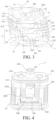
- FIG. 4 is a schematic structural diagram of a mounting base in an electronic atomization device according to a first embodiment of the present disclosure
- FIG. 5 is a schematic structural diagram of a mounting base in an electronic atomization device according to a second embodiment of the present disclosure
- FIG. 6 is a schematic structural diagram of a mounting base in an electronic atomization device according to a third embodiment of the present disclosure
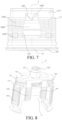
- FIG. 7 is a schematic structural diagram of a mounting base in an electronic atomization device according to a fourth embodiment of the present disclosure.
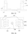
- a leaked liquid buffer structure 122, a condensate collecting structure 14, and an air exchange channel 15 are provided on the mounting base 1.
- the leaked liquid buffer structure 122 is in communication with the condensate collecting structure 14, the leaked liquid buffer structure 122 is in communication with the air exchange channel 15, and the air exchange channel 15 is in communication with the liquid storage tank 4. Liquid leaked from the air exchange channel 15 and liquid leaked from the condensate collecting structure 14 may both reflux, through the leaked liquid buffer structure 122, to the porous substrate 21 in contact with the leaked liquid buffer structure.
- the mounting base 1 includes an atomization cavity 125, and the mounting base 1 includes an air inlet end and an air outlet end, where the air inlet end is provided at the bottom of the atomization cavity 125, and the air outlet end is provided on the end portion of the mounting base 1 away from the air inlet end.
- the mounting base 1 includes an upper base body 11 and a lower base body 12, and the upper base body 11 and the lower base body 12 are connected via a buckle.
- An air outlet hole 128 is defined on the end portion of the upper base body 11 away from the lower base body 12, and the air outlet hole 128 serves as the air outlet end of the mounting base 1.
- An air inlet hole 126 is defined on the end portion of the lower base body 12 away from the upper base body 11, the air inlet hole 126 is defined at the bottom of the atomization cavity 125, and the air inlet hole 126 serves as the air inlet end of the mounting base 1.
- a liquid flowing hole 111 is defined on the end portion provided with the air outlet hole 128 of the upper base body 11, and the liquid in the liquid storage tank 4 flows to the atomization core 2 via the liquid flowing hole 111. There may be two liquid flowing holes 111, and the two liquid flowing holes 111 may be symmetrically defined on the two sides of the air outlet hole 128.
- the mounting base 1 defines an airflow channel 13 communicating the air inlet end and the air outlet end.
- a part of the airflow channel 13 close to the air inlet end is an atomization cavity 125, and a part of the airflow channel close to the air outlet end is an air outlet channel 131.
- Liquid atomized by the atomization core 2 enters the air outlet channel 131 from the atomization cavity 125, and then enters a mouth of a user via a mouthpiece.
- the condensate collecting structure 14 is provided on the mounting base 1, and the condensate collecting structure 14 is provided in the airflow channel 13 and located between the bottom of the atomization cavity 125 and the air outlet channel 131.
- the condensate collecting structure 14 is configured to collect liquid condensed and left in the air outlet channel 131. That is, the airflow channel 13 may be divided into three parts, where a first part is the atomization cavity 125 close to the air inlet end, a third part is the air outlet channel 131 close to the air outlet end, and a second part communicates the atomization cavity 125 with the air outlet channel 131.
- the condensate collecting structure 14 is provided on the second part. In another optional embodiment, the condensate collecting structure 14 is provided in the first part and the second part, and the condensate collecting structure 14 and the bottom of the atomization cavity 125 are provided at intervals.
- a condensate collecting structure 14 is provided on the mounting base 1, and atomized gas in the atomization cavity 125 passes through the condensate collecting structure 14 and enters the air outlet channel; and the condensate collecting structure is configured to collect the liquid condensed and left in the air outlet channel.
- the air outlet channel is located right above the atomization cavity, the top of the mounting base is located between the atomization cavity and the air outlet channel, and the atomized gas in the atomization cavity bypasses the top of the mounting base from at least one side and enters the air outlet channel; and the condensate collecting structure includes a capillary groove structure defined on the at least one side of the top of the mounting base.
- the air outlet hole 128 is defined on the air outlet end of the mounting base 1, and the air outlet hole 128 extends in a direction away from the upper base body 11 to define an air outlet tube 132 and further define the air outlet channel 131.
- the condensate collecting structure 14 includes a first liquid collecting portion 141 and a second liquid collecting portion 143, where the first liquid collecting portion 141 is provided on a blocking portion 142; and the second liquid collecting portion 143 is provided on the outer surface of the mounting base 1, and the second liquid collecting portion 143 is in communication with the first liquid collecting portion 141.
- the air outlet hole 128 is defined on the air outlet end of the mounting base 1, the air outlet end is provided on the upper base body 11, and the air outlet hole 128 extends in the direction away from the upper base body 11 to define the air outlet tube 132 and further define the air outlet channel 131, where the air outlet hole 128 and the air outlet tube 132 are integrally formed.
- the air outlet tube 132 and the upper base body 11 are independently provided, one of the ends of the air outlet tube 132 is inserted in the air outlet hole 128, and the other of the ends is exposed to the outside of the upper base body 11.
- the blocking portion 142 is provided on the mounting base 1. Specifically, the blocking portion 142 is provided on the upper base body 11.
- the blocking portion 142 is a U-shaped structure, an opening 31 of the blocking portion 142 directly faces the atomization cavity 125, and the bottom of the blocking portion 142 directly faces the air outlet channel 131.
- the blocking portion 142 includes a first fluid-guide plate 1421, a second fluid-guide plate 1422, and a third fluid-guide plate 1423.
- the first fluid-guide plate 1421 is perpendicular to the axial of the air outlet channel 131, the first fluid-guide plate 1421 is provided on the end portion of the air outlet channel 131 close to the atomization cavity 125, and the first fluid-guide plate 1421 and the end portion of the air outlet channel 131 are provided at intervals.
- the second fluid-guide plate 1422 is connected to one of the sides of the first fluid-guide plate 1421, and the third fluid-guide plate 1423 is connected to the other of the sides of the first fluid-guide plate 1421.
- the second fluid-guide plate 1422 is provided opposite to the third fluid-guide plate 1423 and is provided on the side of the first fluid-guide plate 1421 away from the air outlet channel 131, and the second fluid-guide plate 1422 and the third fluid-guide plate 1423 are exposed to the mounting base 1 via a window 117 provided on the mounting base 1.
- the first fluid-guide plate 1421, the second fluid-guide plate 1422, and the third fluid-guide plate 1423 are integrally formed.
- the blocking portion 142 and the inner surface of the upper base body 11 define an inner cavity for accommodating the atomization core 2, and the liquid storage tank 4 is in communication with the inner cavity of the blocking portion 142.
- a window 117 is defined on the side wall of the upper base body 11.
- the window 117 is a groove structure with the opening 31 facing the lower base body 12, and the window 117 communicates a gap between the air outlet channel 131 and the first fluid-guide plate 1421 with the outside of the upper base body 11.
- the window 117 further exposes opposite surfaces of the second fluid-guide plate 1422 and the third fluid-guide plate 1423, and the window 117 communicates the atomization cavity 125 with the outside of the upper base body 11.
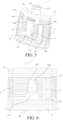
- FIG. 8 is a schematic structural diagram of an upper base body in an electronic atomization device according to a first embodiment of the present disclosure.
- junction of the first fluid-guide plate 1421 and the second fluid-guide plate 1422, and the junction of the first fluid-guide plate 1421 the third fluid-guide plate 1423 are inclined surfaces.
- the junctions of the first fluid-guide plate 1421 with the second fluid-guide plate 1422 and the third fluid-guide plate 1423 are cambered surfaces. In this way, it is convenient for the first fluid-guide plate 1421 to collect condensate in the air outlet channel 131 and guide the liquid to the second fluid-guide plate 1422 and/or the third fluid-guide plate 1423.
- the condensate collecting structure 14 is provided in the airflow channel 13.
- the condensate collecting structure 14 is provided between the atomization cavity 125 and the air outlet channel 131, or may be provided between the air outlet channel 131 and the bottom of the atomization cavity 125.
- the first fluid-guide plate 1421 is a V-shaped structure.
- the V-shaped structure serves as the first liquid collecting portion 141 and is configured to collect cigarette liquid condensed and left in the air outlet channel 131, and the cigarette liquid collected in the V-shaped structure may overflow to the second fluid-guide plate 1422 and/or the third fluid-guide plate 1423.
- the first fluid-guide plate 1421 is a U-shaped structure.
- the U-shaped structure serves as the first liquid collecting portion 141 and is configured to collect cigarette liquid condensed and left in the air outlet channel 131, and the cigarette liquid collected in the U-shaped structure may overflow to the second fluid-guide plate 1422 and/or the third fluid-guide plate 1423.
- a third capillary groove 1431 is defined on the first fluid-guide plate 1421.
- the third capillary groove 1431 serves as the first liquid collecting portion 141, and end portions of the third capillary groove 1431 are in communication with the cambered surfaces or the inclined surfaces, so that the condensate in the third capillary groove 1431 may overflow to the second fluid-guide plate 1422 and/or the third fluid-guide plate 1423.
- the third capillary groove 1431 may extend to the second fluid-guide plate 1422 and/or the third fluid-guide plate 1423. Specifically, the end portions of the third capillary groove 1431 are in direct communication with the second liquid collecting portion 143.
- FIG. 9 is a schematic structural diagram of an upper base body in an electronic atomization device according to a second embodiment of the present disclosure.
- a fourth capillary groove 1432 is defined on the outer surface of the mounting base 1, and the fourth capillary groove 1432 is horizontally provided on the outer surface of the mounting base 1. That is, a direction in which the fourth capillary groove 1432 is provided is perpendicular to a flowing direction of the airflow channel 13.
- the fourth capillary groove 1432 serves as the second liquid collecting portion 143.
- the fourth capillary groove 1432 is defined on the outer surface on the two sides of the window 117 of the mounting base 1, the end portions of the fourth capillary groove 1432 are exposed through the window 117 provided on the mounting base 1, the end portions of the fourth capillary groove 1432 are in communication with the second fluid-guide plate 1422 and the third fluid-guide plate 1423, and the end portions of the fourth capillary groove 1432 are in direct communication with the end portions of the third capillary groove 1431.
- the bottom of the fourth capillary groove 1432 is flush with the surface of the second fluid-guide plate 1422 exposed through the window 117 or the surface of the third fluid-guide plate 1423 exposed through the window 117.
- the end portions of the plurality of fourth capillary grooves 1432 close to the window 117 may be all connected to the second fluid-guide plate 1422 and the third fluid-guide plate 1423, and the end portions of the plurality of fourth capillary grooves 1432 close to the window 117 may be partially connected to the second fluid-guide plate 1422 and/or the third fluid-guide plate 1423.
- the fourth capillary groove 1432 may collect the condensate overflowed from the first liquid collecting portion 141 by a capillary force. That is, when the condensate in the third capillary groove 1431 overflows to the exposed surface of the second fluid-guide plate 1422 and/or the exposed surface of the third fluid-guide plate 1423, when the condensate overflowed to the second fluid-guide plate 1422 and/or the third fluid-guide plate 1423 gathers and does not exceed surface tension of the condensate or does not exceed gravity of the condensed, namely, when the condensate does not depart from the third fluid-guide plate 1423 or the second fluid-guide plate 1422, the end portion of the fourth capillary groove 1432 in communication with the second fluid-guide plate 1422 or the third fluid-guide plate 1423 absorbs the condensate by a capillary force, to absorb the condensate on the second fluid-guide plate 1422 or the third fluid-guide plate 1423 to the fourth capillary groove 1432.
- the condensate may flow, due to the action of gravity, to a cavity defined by the window 117 and an atomizer shell 209.
- the end portion of the fourth capillary groove 1432 is exposed through the window 117, namely, the fourth capillary groove 1432 is in communication with the window 117, the end portion of the fourth capillary groove 1432 may absorb, by a capillary force, the condensate in the cavity defined by the window 117 and the atomizer shell 209, to collect the condensate in the fourth capillary groove 1432.
- a liquid collecting hole 1435 may be further defined on the outer surface of the mounting base 1.
- the liquid collecting hole 1435 is defined on the end portion of the fourth capillary groove 1432 away from the window 117, and the liquid collecting hole 1435 may be in communication with the ends of all the fourth capillary grooves 1432 away from the window 117 or may be in communication with the ends of some fourth capillary grooves 1432 away from the window 117.
- An air guide groove structure 151 is defined on the upper base body 11.
- the air guide groove structure 151 is defined on the outer surface of the upper base body 11, a direction in which the air guide groove structure 151 is provided extends from an end portion close to the lower base body 12 to an end portion provided with the air outlet hole 128 of the upper base body 11, the air guide groove structure 151 is in direct communication with an air guide hole structure 152 defined on the end surface provided with the air outlet hole 128 of the upper base body 11, and the air inlet hole 126 communicates the air guide groove structure 151 with the liquid storage tank 4.
- the atomizer shell 209 covers the opening 31 of the air guide groove structure 151 to define the air exchange channel 15, and the air exchange channel 15 is configured to transmit external air to the liquid storage tank 4, to balance the air pressure of the liquid storage tank 4 and the atomization cavity 125.
- One of the ends of the air exchange channel 15 is in communication with the liquid storage tank 4 via the air guide hole structure 152, and the other of the ends of the air exchange channel 15 is defined on the end portion of the upper base body 11 close to the lower base body 12, so that the air exchange channel 15 is in communication with the atomization cavity 125 via a gap between the upper base body 11 and the lower base body 12.
- FIG. 10 Refer to FIG. 10, FIG.
- FIG. 10 is a schematic structural diagram of a lower base body in an electronic atomization device according to a first embodiment of the present disclosure.
- An air exchange communication groove 159 is provided on the lower base body 12, and the air exchange communication groove 159 is configured to communicate the air exchange channel 15 with the atomization cavity 125.
- the air exchange communication groove 159 is defined at a corresponding position of the air exchange channel 15 and the lower base body 12.
- a fifth capillary groove 1433 is further defined on the upper base body 11, the condensate collecting structure 14 includes the fifth capillary groove 1433, and the fifth capillary groove 1433 is defined on the outer surface of the upper base body 11.
- the fifth capillary groove 1433 is defined on the two sides of the air exchange channel 15 and is in communication with the air exchange channel 15, and the fifth capillary groove 1433 is configured to collect liquid leaked from the air guide hole structure 152 to the air exchange channel 15.
- a direction in which the plurality of fifth capillary grooves 1433 are provided may be the same as the direction in which the fourth capillary groove 1432 is provided, namely, the direction in which the fifth capillary groove 1433 is provided is perpendicular to a direction in which the air exchange channel 15 is provided.
- the end portion of the fifth capillary groove 1433 away from the air exchange channel 15 is in communication with the end portion of the fourth capillary groove 1432 away from the window 117.
- the end portion of the fifth capillary groove 1433 away from the air exchange channel 15 is in communication with the liquid collecting hole 1435.
- the condensate collecting structure 14 includes a sixth capillary groove 1434.
- the sixth capillary groove 1434 is defined on the inner surface of the air outlet channel 131, and the sixth capillary groove 1434 is configured to absorb condensate in the air outlet channel 131, to prevent the condensate in the air outlet channel 131 from dripping to the atomization cavity 125.
- the liquid in the liquid storage tank 4 When the air pressure in the liquid storage tank 4 increases, the liquid in the liquid storage tank 4 is pressed to overflow to the air exchange channel 15, and the fifth capillary groove 1433 may lock the liquid in the air exchange channel 15 by a capillary force.
- the air pressure in the liquid storage tank 4 decreases, the air pressure in the fifth capillary groove 1433 is greater than the air pressure in the liquid storage tank 4, and the liquid in the fifth capillary groove 1433 refluxes to the liquid storage tank 4 through the air exchange channel 15.
- an air guide groove structure 151 is defined on the outer surface of the upper base body 11.
- the air guide groove structure 151 is defined on the outer surface of the upper base body 11 close to the air outlet end
- a recess portion is defined on the outer surface of the upper base body 11 close to the lower base body 12
- the recess portion is in communication with the air guide groove structure 151
- the atomizer shell 209 covers the recess portion and the air guide groove structure 151 to define the air exchange channel 15.
- the air exchange channel 15 further serves as a liquid collecting tank collecting liquid left in the condensate collecting structure 14 and/or the air exchange channel 15.
- One of the ends of the air guide groove structure 151 is in communication with the liquid storage tank 4 through the air guide hole structure 152, and the other of the ends of the air guide groove structure is in communication with the recess portion.
- An air inlet of the air exchange channel 15 is defined on the side wall of the upper base body 11. That is, the air inlet of the air exchange channel 15 is defined on the bottom wall 301 of the recess portion and communicates the atomization cavity 125 with the recess portion.
- An air outlet of the air exchange channel 15 is in communication with the liquid storage tank 4 via the air guide hole structure 152. The position of the air inlet is higher than the bottom of the liquid collecting tank, so that leaked liquid in the air exchange channel 15 may be collected from the air inlet to the bottom of the liquid collecting tank.
- FIG. 11 is a schematic structural diagram of a first seal member in an electronic atomization device according to an embodiment of the present disclosure.
- An air outlet through hole 162 and a liquid flowing through hole 163 are defined on the first seal member 316.
- the liquid in the liquid storage tank 4 enters a liquid flowing cavity 116 via the liquid flowing through hole 163, and the air outlet through hole 162 is configured to run through the air outlet tube 132.
- a one-way valve 161 matching the end opening of the air exchange channel 15 is provided on the first seal member 316, and the one-way valve 161 is configured to block the liquid in the liquid storage tank 4 from leaking to the air exchange channel 15; and when the air pressure in the liquid storage tank 4 is less than the external air pressure, air in the air exchange channel 15 may open the one-way valve 161 by pushing to cause the one-way valve 161 to open toward the liquid storage tank 4, so that the air enters the liquid storage tank 4, and the leaked liquid refluxes to the liquid storage tank 4 via the air exchange channel 15.
- the mounting base 1 includes a housing 113 and a separating plate 114 provided in the housing 113, the separating plate 114 includes a liquid flowing hole 111, and the liquid flowing hole 111 is connected to the liquid storage tank 4, namely, the liquid flowing hole 111 is in communication with the liquid storage tank 4.
- the separating plate 114 divides a space in the housing 113 into the liquid flowing cavity 116 and an access cavity 115, the liquid flowing cavity 116 is in communication with the access cavity 115 via the separating plate 114, and same sides of the housing 113 and the liquid flowing cavity 116 further define the air outlet channel 131.
- the mounting base 1 is embedded in the atomizer shell 209, a vent tube is connected to the air outlet channel 131, and smoke in the atomization cavity 125 passes through the airflow channel 13 and the vent tube, and is guided to the mouth of the user.
- the mounting base 1 may not be embedded in the atomizer shell 209 provided that the liquid flowing hole 111 is in communication with the liquid storage tank 4.
- the liquid storage tank 4 is a flexible liquid tank, a liquid storage ball, or the like, and connected to the separating plate 114, and the liquid storage tank 4 is in communication with the liquid flowing hole 111.
- the separating plate 114 may be a plate with the liquid flowing hole 111 defined at a middle part, or the separating plate 114 is a plate with a plurality of liquid flowing holes 111 defined at the middle part, provided that the liquid flowing hole 111 defined on the separating plate 114 can be in communication with the liquid storage tank 4, which is not limited in the present disclosure.
- the atomization core 2 is assembled in the access cavity 115 and blocks the liquid flowing cavity 116, the atomization core 2 is in communication with the liquid flowing cavity 116, and the liquid flowing cavity 116 and the liquid flowing hole 111 guide cigarette liquid to the atomization core 2, to help the atomization core 2 atomize the cigarette liquid to form smoke.
- a seal member 3 is provided on the side of the separating plate 114 facing away from the liquid storage tank 4 and located between the separating plate 114 and the atomization core 2, and the atomization core 2 abuts against the seal member 3 to prevent the cigarette liquid from leaking.
- the seal member 3 includes the opening 31 in communication with the liquid flowing hole 111, so that the opening 31 is in communication with the liquid storage tank 4, and the cigarette liquid enters the atomization core 2 via the opening 31.
- the lower base body 12 is connected to and seals the end of the upper base body 11 facing away from the liquid storage tank 4, and the lower base body 12 abuts against the atomization core 2, so that the atomization core 2 abuts against the seal member 3, and a space formed between the upper base body 11, the atomization core 2, and the lower base body 12 defines the atomization cavity 125.
- the atomization core 2 atomizes the cigarette liquid and forms the smoke in the atomization cavity 125, and the atomization cavity 125 is in communication with the airflow channel 13.
- an air guide groove structure 151 is defined between the mounting base 1 and the seal member 3, and the air guide groove structure 151 communicates the liquid storage tank 4 with external air. After the cigarette liquid is stored in a liquid storage space, the air guide groove structure 151 is liquid sealed by the cigarette liquid.
- the air guide groove structure 151 may communicate the atomization cavity 125 with the liquid storage tank 4, and further communicate the liquid storage tank 4 with the external air via the atomization cavity 125.
- the air guide groove structure 151 is defined between the mounting base 1 and the seal member 3, and the air guide groove structure 151 communicates the liquid storage tank 4 with the atomization cavity 125. Therefore, by adjusting the cigarette liquid stored in the air guide groove structure 151, the air pressure and hydraulic pressure in the liquid storage tank 4, capillary tension and resistance of the air guide groove structure 151 to the cigarette liquid, and the air pressure reach dynamic balance, thereby preventing occurrence of non-smooth liquid flowing and liquid leakage of the atomizer 10 and improving the quality of the atomizer 10.
- the air in the atomization cavity 125 may enter the liquid storage tank 4 via the air guide groove structure 151 to implement air exchange. Therefore, the air pressure in the liquid storage tank 4 increases, thereby preventing occurrence of non-smooth liquid flowing caused by excessively low air pressure in the cavity and improving the quality of the atomizer 10.
- the air pressure in the liquid storage tank 4 increases due to heating, the amount of cigarette liquid entering the air guide groove structure 151 may increase, to further appropriately decrease the air pressure in the liquid storage tank 4, thereby preventing occurrence of liquid leakage and also improving the quality of the atomizer 10.
- the air guide groove structure 151 is defined on the seal member 3. Specifically, the air guide groove structure 151 is provided on the side of the seal member 3 facing the separating plate 114 and/or the side of the seal member 3 facing the atomization core 2, or the air guide groove structure 151 may be defined in the seal member 3.
- FIG. 12 is a schematic structural diagram of a seal member in an electronic atomization device according to an embodiment of the present disclosure.
- Six air guide groove structures 151 are defined on the side of the seal member 3 facing the separating plate 114 and/or the side of the seal member 3 facing the atomization core 2, which can conveniently adjust the air pressure in the liquid storage tank 4.
- FIG. 13 is a schematic structural diagram of an air exchange channel in an electronic atomization device according to a first embodiment of the present disclosure.
- the air guide groove structure 151 is defined on the side of the separating plate 114 facing away from the liquid storage tank 4, and the air guide groove structure 151 is sealed by the seal member 3, so that the air guide groove structure 151 only exposes an air guide hole to be in communication with the liquid flowing hole 111 and exposes the air inlet hole 126 to be in communication with the atomization cavity 125.
- the air guide groove structures 151 are all located on the side of the separating plate 114 facing away from the liquid storage tank 4, so that cigarette liquid in the air guide groove structures 151 has the same hydraulic pressure value.
- the air guide groove structure 151 may be circuitously defined on the separating plate 114, which may increase the flowing resistance of leakage of the cigarette liquid in the air guide groove structure 151 and extend a leakage path of the cigarette liquid.
- the air guide groove structure 151 may be linearly provided, provided that the air guide groove structure 151 can communicate the liquid flowing hole 111 with air, which is not limited in the present disclosure.
- the plurality of air guide groove structures 151 may perform air exchange at the same time to increase the air pressure in the liquid storage tank 4, and liquid may enter the plurality of air guide groove structures 151 at the same time to decrease the air pressure in the liquid storage tank 4. Therefore, the convenience of adjusting the air pressure in the liquid storage tank 4 can be increased by using the plurality of air guide groove structures 151, so that the air pressure in the liquid storage tank 4 can be quickly adjusted.
- a buffer groove 153 is further defined on the side of the separating plate 114 facing away from the liquid storage tank 4.
- the air guide groove structure 151 flows through the buffer groove 153, the cross-sectional area of the buffer groove 153 in a path direction of the air guide groove structure 151 is greater than the cross-sectional area of the air guide groove structure 151 in the same direction, and the seal member 3 seals the air guide groove structure 151 and the buffer groove 153, to prevent liquid leakage of the air guide groove structure 151 and the buffer groove 153.
- the buffer groove 153 is configured to buffer cigarette liquid, and the cross-sectional area of the buffer groove 153 in the path direction of the air guide groove structure 151 is greater than the cross-sectional area of the air guide groove structure 151 in the same direction, so that the liquid storage capability of the air guide groove structure 151 can be improved to prevent the cigarette liquid from leaking from the air guide groove structure 151.
- the depth of the air guide groove structure 151 should be set to be in a range from 0.1 mm to 0.5 mm
- the width of the air guide groove structure 151 in a direction perpendicular to the path direction thereof should be set to be in a range from 0.1 mm to 0.5 mm
- the width of the buffer groove 153 is greater than the width of the air guide groove structure 151
- the depth of the buffer groove 153 is greater than or equal to the depth of the air guide groove structure 151.
- the air inlet hole 126 of one air guide groove structure 151 is adjacent to an air exchange opening of another air guide groove structure 151
- an air exchange opening of the air guide groove structure 151 is adjacent to the air inlet hole 126 of the another air guide groove structure 151
- the two air guide groove structures 151 are engaged with each other and are provided surrounding the liquid flowing hole 111
- the vent openings are in communication with the liquid storage tank 4
- the air inlet holes 126 are in communication with the air.
- the air guide groove structure 151 may have a long length and can store more cigarette liquid, the air pressure in the liquid storage tank 4 can be also adjusted conveniently, and the vent openings of the two air guide groove structures 151 are provided at different positions, so that the liquid flowing difficulty of the cigarette liquid may be prevented from increasing due to aggregation of bubbles generated by vent openings at the same position.
- the length and the cross-sectional area of the air guide groove structure 151 and the length and the cross-sectional area of the buffer groove 153 may be set according to a specification of the atomizer 10, to help adjust the air pressure in the liquid storage tank 4.
- an air exchange channel 15 is defined on the separating plate 114 of the upper base body 11, and the air exchange channel 15 includes an air guide hole structure 152 and an air guide groove structure 151.
- the air guide hole structure 152 penetrates the separating plate 114, the air guide hole structure 152 and the liquid flowing hole 111 are provided at intervals, and the air guide hole structure 152 communicates the liquid flowing cavity 116 with the access cavity 115.
- the air guide groove structure 151 is defined on the side of the separating plate 114 facing away from the liquid flowing cavity 116, one of the ends of the air guide groove structure 151 is in communication with the end of the air guide hole structure 152 facing away from the liquid flowing cavity 116, and the other of the ends of the air guide groove structure 151 extends in a direction away from the air guide hole structure 152 and is in communication with the atomization cavity 125.
- the other end of the air guide groove structure 151 may be in direct communication with the external air.
- the cross section of the air guide hole structure 152 may be in at least one shape of a circle, an ellipse, a rectangle, or a semi-circle, or may be in another shape which facilitates ventilation.
- a silica gel seal ring is provided between the upper base body 11 and the atomization core 2, the silica gel seal ring abuts against the end of the air guide hole structure 152 connected to the air guide groove structure 151, and the side wall of the silica gel seal ring abuts against the opening 31 of the air guide groove structure 151, so that the air guide hole structure 152 and the air guide groove structure 151 define the air exchange channel 15 between the separating plate 114 and the silica gel seal ring.
- the size may be the depth of the air guide groove structure 151 and the width of the air guide groove structure 151.
- FIG. 14 is a schematic structural diagram of an air exchange channel in an electronic atomization device according to a second embodiment of the present disclosure.
- the air exchange channel 15 includes the air guide hole structure 152 and the air guide groove structure 151.
- the air guide hole structure 152 is defined on the separating plate 114 and is defined at intervals with the liquid flowing hole 111. Specifically, there may be one or a plurality of air guide hole structures 152.
- the air guide hole structure 152 includes a first air guide hole 1521 and a second air guide hole 1522
- the air guide groove structure 151 includes a first air guide groove 1511 and a second air guide groove 1512
- the first air guide hole 1521 and the second air guide hole 1522 are defined on the two sides of the liquid flowing hole 111 at intervals and symmetrically.
- the first air guide groove 1511 is in communication with the end of the first air guide hole 1521 facing away from the liquid flowing cavity 116
- the second air guide groove 1512 is in communication with the end of the second air guide hole 1522 facing away from the liquid flowing cavity 116
- the first air guide groove 1511 and the second air guide groove 1512 both extend along the inner surface of the access cavity 115 in a direction away from the first air guide hole 1521 and the second air guide hole 1522. Therefore, the end of the first air guide groove 1511 away from the first air guide hole 1521 is in communication with the atomization cavity 125; and the end of the second air guide groove 1512 away from the second air guide hole 1522 is in communication with the atomization cavity 125.
- the first air guide hole 1521 is in communication with the first air guide groove 1511; and the second air guide hole 1522 is in communication with the second air guide groove 1512.
- the end portion of the first air guide groove 1511 away from the first air guide hole 1521 and the end portion of the second air guide groove 1512 away from the second air guide hole 1522 extend along the inner surface of the access cavity 115 in a direction away from the separating plate 114.
- the first air guide groove 1511 and the second air guide groove 1512 may be defined symmetrically or asymmetrically, provided that air in the atomization cavity 125 can enter the liquid storage tank 4 via the first air guide groove 1511 and the second air guide groove 1512 and the first air guide hole 1521 and the second air guide hole 1522 connected thereto.
- the end portions of the first air guide groove 1511 away from the first air guide hole 1521 and the second air guide groove 1512 away from the second air guide hole 1522 pass through the housing 113 and are in direct communication with the external air.
- the end portion of the first air guide groove 1511 away from the first air guide hole 1521 is in communication with the atomization cavity 125 and is in communication with the external air via the air inlet hole 126 at the bottom of the atomization cavity 125, and the end portion of the second air guide groove 1512 away from the second air guide hole 1522 passes through the housing 113 and is in direct communication with the external air.
- FIG. 15 is a schematic structural diagram of an air exchange channel in an electronic atomization device according to a third embodiment of the present disclosure.
- the air guide groove structure 151 further includes a third air guide groove 1513 and a fourth air guide groove 1514.
- One of the ends of the third air guide groove 1513 is in communication with the first air guide hole 1521, and the other of the ends of the third air guide groove 1513 is in communication with the liquid flowing hole 111.
- One of the ends of the fourth air guide groove 1514 is in communication with the second air guide hole 1522, and the other of the ends of the fourth air guide groove 1514 is in communication with the liquid flowing hole 111.
- the third air guide groove 1513 can transmit the air transmitted in the first air guide groove 1511 via the liquid flowing hole 111
- the fourth air guide groove 1514 can transmit the air transmitted in the second air guide groove 1512 via the liquid flowing hole 111, so that the first air guide hole 1521, the second air guide hole 1522, and the liquid flowing hole 111 perform air transmission at the same time, thereby shortening a duration for balancing the air pressure in the liquid storage tank 4 and the external air pressure.
- one of the ends of the first air guide groove 1511 is in communication with the atomization cavity 125, and the other of the ends is in communication with the first air guide hole 1521.
- One of the ends of the third air guide groove is in direct communication with the atomization cavity 125 or the external air, and the other of the ends is in communication with the liquid flowing hole 111.
- One of the ends of the second air guide groove 1512 is in communication with the atomization cavity 125, and the other of the ends is in communication with the second air guide hole 1522.
- One of the ends of the fourth air guide groove 1514 is in direct communication with the atomization cavity 125 or the external air, and the other of the ends is in communication with the liquid flowing hole 111.
- FIG. 16 is a schematic structural diagram of an air exchange channel in an electronic atomization device according to a fourth embodiment of the present disclosure.
- the air exchange channel 15 includes an air guide hole structure 152 and an air guide groove structure 151 connected to the air guide hole structure 152.
- the air guide groove structure 151 includes a first air guide groove 1511 and a second air guide groove 1512
- the air guide hole structure 152 includes a first air guide hole 1521 and a second air guide hole 1522.
- the first air guide hole 1521 and the second air guide hole 1522 are both defined on the separating plate 114 and provided at intervals with the liquid flowing hole 111.
- the first air guide hole 1521 and the second air guide hole 1522 are symmetrically defined on the two sides of the liquid flowing hole 111.
- the first air guide groove 1511 and the second air guide groove 1512 are symmetrically defined on the two sides of the liquid flowing hole 111, and the first air guide groove 1511 and the second air guide groove 1512 are defined on the side of the separating plate 114 facing away from the liquid flowing cavity 116.
- the first air guide groove 1511 is in communication with the end of the first air guide hole 1521 facing away from the liquid flowing cavity 116, the two ends of the first air guide groove 1511 extend along the inner surface of the access cavity 115 in a direction away from the first air guide hole 1521, and the two ends of the first air guide groove 1511 are both in communication with the atomization cavity 125.
- the second air guide groove 1512 is in communication with the end of the second air guide hole 1522 facing away from the liquid flowing cavity 116, the two ends of the second air guide groove 1512 extend along the inner surface of the access cavity 115 in a direction away from the second air guide hole 1522, and the two ends of the second air guide groove 1512 are both in communication with the atomization cavity 125.
- the end portion of the first air guide groove 1511 away from the first air guide hole 1521 and the end portion of the second air guide groove 1512 away from the second air guide hole 1522 can both pass through the housing 113 and be in direct communication with the external air.
- At least one end portion of the end portion of the first air guide groove 1511 away from the first air guide hole 1521 and the end portion of the second air guide groove 1512 away from the second air guide hole 1522 can pass through the housing 113 and be in direct communication with the external air, and the remaining end portion is in communication with the atomization cavity 125 to be in communication with the external air through the air inlet hole 126 at the bottom of the atomization cavity 125.
- FIG. 17 is a schematic structural diagram of an air exchange channel in an electronic atomization device according to a fifth embodiment of the present disclosure.
- the air guide groove structure 151 further includes a third air guide groove 1513 and a fourth air guide groove 1514.
- One of the ends of the third air guide groove 1513 is in communication with the first air guide hole 1521, and the other of the ends is in communication with the liquid flowing hole 111.
- One of the ends of the fourth air guide groove 1514 is in communication with the second air guide hole 1522, and the other of the ends is in communication with the liquid flowing hole 111.
- the third air guide groove 1513 can transmit the air transmitted in the first air guide groove 1511 through the liquid flowing hole 111
- the fourth air guide groove 1514 can transmit the air transmitted in the second air guide groove 1512 through the liquid flowing hole 111, so that the first air guide hole 1521, the second air guide hole 1522, and the liquid flowing hole 111 perform air transmission at the same time, thereby shortening a duration for balancing the air pressure in the liquid storage tank 4 and the external air pressure.
- one of the ends of the first air guide groove 1511 is in communication with the atomization cavity 125 or the external air, and the other of the ends is in communication with the first air guide hole 1521.
- One of the ends of the third air guide groove 1513 is in direct communication with the atomization cavity 125, and the other of the ends is in communication with the liquid flowing hole 111.
- One of the ends of the second air guide groove 1512 is in communication with the atomization cavity 125, and the other of the ends is in communication with the second air guide hole 1522.
- One of the ends of the fourth air guide groove 1514 is in direct communication with the atomization cavity 125, and the other of the ends is in communication with the liquid flowing hole 111.
- FIG. 18 is a schematic structural diagram of an air exchange channel in an electronic atomization device according to a sixth embodiment of the present disclosure.
- the air exchange channel 15 includes an air guide hole structure 152 and an air guide groove structure 151 connected to the air guide hole structure 152.
- the air guide groove structure 151 includes a first air guide groove 1511, a second air guide groove 1512, and a connection groove 158
- the air guide hole structure 152 includes a first air guide hole 1521 and a second air guide hole 1522.
- the first air guide hole 1521 and the second air guide hole 1522 are both defined on the separating plate 114 and provided at intervals with the liquid flowing hole 111.
- the first air guide hole 1521 and the second air guide hole 1522 are symmetrically defined on the two sides of the liquid flowing hole 111.
- the first air guide groove 1511 and the second air guide groove 1512 are defined on the side of the separating plate 114 facing away from the liquid flowing cavity 116.
- the first air guide groove 1511 is in communication with the end of the first air guide hole 1521 facing away from the liquid flowing cavity 116, the two ends of the first air guide groove 1511 extend along the inner surface of the access cavity 115 in a direction away from the first air guide hole 1521, and the two ends of the first air guide groove 1511 are both in communication with the atomization cavity 125.
- the second air guide groove 1512 is in communication with the end of the second air guide hole 1522 facing away from the liquid flowing cavity 116, the two ends of the second air guide groove 1512 extend along the inner surface of the access cavity 115 in a direction away from the second air guide hole 1522, and the two ends of the second air guide groove 1512 are both in communication with the atomization cavity 125.
- the second air guide groove 1512 and the first air guide groove 1511 may be in communication with each other via the connection groove 158.
- connection groove 158 can conduct the air transmitted in the first air guide groove 1511 to the second air guide hole 1522 and can also conduct the air transmitted in the second air guide groove 1512 to the first air guide hole 1521, which more facilitates to balance the air pressure in the liquid storage tank 4 and the external air pressure.
- the end portion of the first air guide groove 1511 away from the first air guide hole 1521 and the end portion of the second air guide groove 1512 away from the second air guide hole 1522 can both pass through the housing 113 and be in direct communication with the external air.
- At least one end portion of the end portion of the first air guide groove 1511 away from the first air guide hole 1521 and the end portion of the second air guide groove 1512 away from the second air guide hole 1522 can pass through the housing 113 and be in direct communication with the external air, and the remaining end portion is in communication with the atomization cavity 125 to be in communication with the external air via the air inlet hole 126 at the bottom of the atomization cavity 125.
- At least one end portion of the end portion of the first air guide groove 1511 away from the first air guide hole 1521 and the end portion of the second air guide groove 1512 away from the second air guide hole 1522 is in communication with the atomization cavity 125 to be in communication with the external air via the air inlet hole 126 at the bottom of the atomization cavity 125, and the remaining end portion can pass through the housing 113 and be in direct communication with the external air.
- FIG. 19 is a schematic structural diagram of an air exchange channel in an electronic atomization device according to a seventh embodiment of the present disclosure.
- the air guide groove structure 151 further includes a third air guide groove 1513 and a fourth air guide groove 1514.
- One of the ends of the third air guide groove 1513 is in communication with the first air guide hole 1521, and the other of the ends is in communication with the liquid flowing hole 111.
- One of the ends of the fourth air guide groove 1514 is in communication with the second air guide hole 1522, and the other of the ends is in communication with the liquid flowing hole 111.
- the third air guide groove 1513 can transmit the air transmitted in the first air guide groove 1511 via the liquid flowing hole 111
- the fourth air guide groove 1514 can transmit the air transmitted in the second air guide groove 1512via the liquid flowing hole 111, so that the first air guide hole 1521, the second air guide hole 1522, and the liquid flowing hole 111 perform air transmission at the same time, thereby shortening a duration for balancing the air pressure in the liquid storage tank 4 and the external air pressure.
- one end of the first air guide groove 1511 is in communication with the atomization cavity 125 or the external air, and another end is in communication with the first air guide hole 1521.
- One of the ends of the third air guide groove 1513 is in direct communication with the atomization cavity 125 or the external air, and the other of the ends is in communication with the liquid flowing hole 111.
- One of the ends of the second air guide groove 1512 is in communication with the atomization cavity 125 or the external air, and the other of the ends is in communication with the second air guide hole 1522.
- One of the ends of the fourth air guide groove 1514 is in direct communication with the atomization cavity 125 or the external air, and the other of the ends is in communication with the liquid flowing hole 111.
- FIG. 20 is a schematic structural diagram of an air exchange channel in an electronic atomization device according to an eighth embodiment of the present disclosure.
- the air exchange channel 15 includes an air guide hole structure 152 and an air guide groove structure 151 connected to the air guide hole structure 152.
- the air guide groove structure 151 includes a first air guide groove 1511 and a second air guide groove 1512
- the air guide hole structure 152 includes a first air guide hole 1521 and a second air guide hole 1522.
- the first air guide hole 1521 and the second air guide hole 1522 are both defined on the separating plate 114 and provided at intervals with the liquid flowing hole 111.
- the first air guide hole 1521 and the second air guide hole 1522 are symmetrically defined on the two sides of the liquid flowing hole 111.
- the first air guide groove 1511 and the second air guide groove 1512 are symmetrically defined on two sides of the liquid flowing hole 111, and the first air guide groove 1511 and the second air guide groove 1512 are defined on the side of the separating plate 114 facing away from the liquid flowing cavity 116.
- One of the ends of the first air guide groove 1511 is in communication with an end portion of the first air guide hole 1521 facing away from the liquid flowing cavity 116, and the other of the ends of the first air guide groove 1511 extends along the separating plate 114 to the position close to the second air guide hole 1522, and extends along the inner surface of the access cavity 115 and is in communication with the atomization cavity 125.
- One of the ends of the second air guide groove 1512 is in communication with an end portion of the second air guide hole 1522 facing away from the liquid flowing cavity 116, and the other of the end of the second air guide groove 1512 extends along the separating plate 114 to the position close to the first air guide hole 1521, and extends along the inner surface of the access cavity 115 and is in communication with the atomization cavity 125, to be in communication with the external air through the air inlet hole 126 provided at the bottom of the atomization cavity 125.
- the end portion of the first air guide groove 1511 away from the first air guide hole 1521 and the end portion of the second air guide groove 1512 away from the second air guide hole 1522 pass through the housing 113 and are in direct communication with the external air.
- the end portion of the end portion of the first air guide groove 1511 away from the first air guide hole 1521 and one of the end portions of the second air guide groove 1512 away from the second air guide hole 1522 pass through the housing 113 and is in direct communication with the external air, and the other of the end portions of the second air guide groove 1512 is in communication with the atomization cavity 125 to be in communication with the external air via the air inlet hole 126 at the bottom of the atomization cavity 125.
- FIG. 21 is a schematic structural diagram of an air exchange channel in an electronic atomization device according to a ninth embodiment of the present disclosure.
- the air guide groove structure 151 further includes a third air guide groove 1513 and a fourth air guide groove 1514.
- One of the ends of the third air guide groove 1513 is in communication with the first air guide hole 1521, and the other of the ends is in communication with the liquid flowing hole 111.
- One of the ends of the fourth air guide groove 1514 is in communication with the second air guide hole 1522, and the other of the ends is in communication with the liquid flowing hole 111.
- the third air guide groove 1513 can transmit the air transmitted in the first air guide groove 1511 through the liquid flowing hole 111
- the fourth air guide groove 1514 can transmit the air transmitted in the second air guide groove 1512 through the liquid flowing hole 111, so that the first air guide hole 1521, the second air guide hole 1522, and the liquid flowing hole 111 perform air transmission at the same time, thereby shortening a duration for balancing the air pressure in the liquid storage tank 4 and the external air pressure.
- one of the ends of the first air guide groove 1511 is in communication with the atomization cavity 125 or the external air, and the other of the ends is in communication with the first air guide hole 1521.
- One of the ends of the third air guide groove 1513 is in direct communication with the atomization cavity 125 or the external air, and the other of the ends is in communication with the liquid flowing hole 111.
- One of the ends of the second air guide groove 1512 is in communication with the atomization cavity 125 or the external air, and the other of the ends is in communication with the second air guide hole 1522.
- One of the ends of the fourth air guide groove 1514 is in direct communication with the atomization cavity 125 or the external air, and the other of the ends is in communication with the liquid flowing hole 111.
- the liquid in the liquid storage tank 4 flows to the atomization core 2 via the liquid flowing hole 111. If the air pressure in the liquid storage tank 4 decreases, a speed at which the liquid in the liquid storage tank 4 flows to the atomization core 2 through the liquid flowing hole 111 is less than a speed at which the atomization core 2 atomizes the liquid. Air is transmitted to the liquid storage tank 4 via the air exchange channel 15, to balance the air pressure in the liquid storage tank 4 and the external air pressure.
- the user inhales the electronic atomization device 100.
- the atomization core 2 atomizes cigarette liquid, the air pressure in the atomization cavity 125 is greater than the air pressure in the liquid storage tank 4, the atomization cavity 125 is in communication with the external air, and the external air enters the atomization cavity 125 via the air inlet hole 126.
- the air in the atomization cavity 125 is pressed into the first air guide groove 1511 and the second air guide groove 1512 due to an air pressure difference, the air in the first air guide groove 1511 enters the liquid storage tank 4 via the first air guide hole 1521, the air in the second air guide groove 1512 enters the liquid storage tank 4 via the second air guide hole 1522, and the air is transmitted to the liquid storage tank 4 via the first air guide hole 1521 and the second air guide hole 1522.
- the air pressure in the liquid storage tank 4 and the air pressure in the atomization cavity 125 are balanced, and the cigarette liquid in the liquid storage tank 4 further enters the atomization core 2 via the liquid flowing hole 111, so that the cigarette liquid in the liquid storage tank 4 can be smoothly transmitted to the atomization core 2 via the liquid flowing hole 111, thereby avoiding dry burning of the atomization core 2.
- the user inhales the electronic atomization device 100.
- the atomization core 2 atomizes cigarette liquid, the external air pressure is greater than the air pressure in the liquid storage tank 4, and the external air is pressed into the first air guide groove 1511 and the second air guide groove 1512 due to an air pressure difference.
- the air in the first air guide groove 1511 enters the liquid storage tank 4 via the first air guide hole 1521
- the air in the second air guide groove 1512 enters the liquid storage tank 4 via the second air guide hole 1522
- the air is transmitted to the liquid storage tank 4 via the first air guide hole 1521 and the second air guide hole 1522.
- the air pressure in the liquid storage tank 4 and the external air pressure are balanced, and the cigarette liquid in the liquid storage tank 4 further enters the atomization core 2 via the liquid flowing hole 111, so that the cigarette liquid in the liquid storage tank 4 can be smoothly transmitted to the atomization core 2 via the liquid flowing hole 111, thereby avoiding dry burning of the atomization core 2.
- the user inhales the electronic atomization device 100.
- the atomization core 2 atomizes cigarette liquid, the air pressure in the atomization cavity 125 is greater than the air pressure in the liquid storage tank 4, the atomization cavity 125 is in communication with the external air, the external air enters the atomization cavity 125 via the air inlet hole 126, the air in the atomization cavity 125 is pressed into the first air guide groove 1511 and the second air guide groove 1512 due to an air pressure difference, and the air in the first air guide groove 1511 enters the liquid storage tank 4 via the first air guide hole 1521.
- the third air guide groove 1513 transmits air that is not transmitted in the first air guide groove 1511 to the liquid storage tank 4 via the liquid flowing hole 111.
- the fourth air guide groove 1514 transmits air that is not transmitted in the second air guide groove 1512 to the liquid storage tank 4 through the liquid flowing hole 111.
- the air pressure in the liquid storage tank 4 and the air pressure in the atomization cavity 125 are balanced, and the cigarette liquid in the liquid storage tank 4 further enters the atomization core 2 via the liquid flowing hole 111, so that the cigarette liquid in the liquid storage tank 4 can be smoothly transmitted to the atomization core 2 via the liquid flowing hole 111, thereby avoiding dry burning of the atomization core 2.
- the atomizer 10 further includes a seal member 3, and the seal member 3 is provided between the mounting base 1 and the atomization core 2.
- the seal member 3 may be a seal ring.
- the porous substrate 21 is made of any one of a porous ceramic or a porous metal.
- the porous substrate 21 is in communication with the liquid stored in the storage tank 4 and absorbs liquid from the liquid storage tank 4 by a capillary force; and the heating element 22 is configured to heat and atomize the liquid of the porous substrate 21.
- the porous substrate 21 includes an cigarette liquid transmission portion 211 and a protruding portion 212 integrally formed on one side of the cigarette liquid transmission portion 211, and the leaked liquid buffer structure 122 is in contact with a periphery of one side surface of the cigarette liquid transmission portion 211 provided with the protruding portion 212.
- a surface of the protruding portion 212 away from the cigarette liquid transmission portion 211 is a atomization surface 214
- a surface of the cigarette liquid transmission portion 211 in contact with cigarette liquid is a liquid absorbing surface 213
- the leaked liquid buffer structure 122 is in contact with an edge of the side surface of the cigarette liquid transmission portion 211 provided with the protruding portion 212. That is, the leaked liquid buffer structure 122 is provided in contact with an edge of the cigarette liquid transmission portion 211 and is provided at intervals with the protruding portion 212, so that the leaked liquid buffer structure 122 can be prevented from being damaged by high temperature of the heating element 22 on the atomization surface 214.
- the heating element 22 is provided on the atomization surface 214.
- the heating element 22 may be a heating film or may be a heating circuit.
- the heating element 22 is electrically connected to an electrode, and one end of the electrode passes through a foundation base 121 to be connected to the power supply assembly 202.
- the cigarette liquid transmission portion 211 and the protruding portion 212 are integrally formed, and the cigarette liquid transmission portion 211 and the protruding portion 212 are both made of porous materials.
- the materials of the cigarette liquid transmission portion 211 and the protruding portion 212 may be a porous ceramic or a porous metal, but are not limited to the two materials, provided that the cigarette liquid in the liquid storage tank 4 can be transmitted to the heating element 22 through capillary action for atomization.
- the cigarette liquid transmission portion 211 only covers a part of the leaked liquid buffer structure 122.
- the capillary force of the porous substrate 21 is greater than the capillary force of the leaked liquid buffer structure 122, and when the heating element 22 heats and atomizes the liquid of the porous substrate 21, the liquid received by the leaked liquid buffer structure 122 may reflux to the porous substrate 21 and is heated and atomized.
- the mounting base 1 includes the atomization cavity 125, the atomization core 2 is accommodated in the atomization cavity 125, and the leaked liquid buffer structure 122 is connected to the bottom of the atomization cavity 125 and absorbs liquid deposited at the bottom of the atomization cavity 125 by a capillary force.
- the mounting base 1 includes the upper base body 11 and the lower base body 12.
- the lower base body 12 includes the foundation base 121, the liquid flowing hole 111 is provided on the upper base body 11, the cigarette liquid in the liquid storage tank 4 flows to the porous substrate 21 through the liquid flowing hole 111.
- the leaked liquid buffer structure 122 is provided on the lower base body 12, the porous substrate 21 includes the liquid absorbing surface 213 and the atomization surface 214, the liquid absorbing surface 213 is connected to the liquid flowing hole 111, the heating element 22 is provided on the atomization surface 214, and the porous substrate 21 is in contact with the leaked liquid buffer structure 122.
- the air pressure in the liquid storage tank 4 increases, the air pressure in the liquid storage tank 4 is greater than the air pressure in the atomization cavity 125, an air pressure difference between the liquid storage tank 4 and the atomization cavity 125 presses the liquid in the liquid storage tank 4 to the porous substrate 21, so that redundant liquid overflows from the porous substrate 21, and the leaked liquid buffer structure 122 receives and locks the overflowed redundant liquid.
- the air pressure in the liquid storage tank 4 decreases, the air pressure in the liquid storage tank 4 is less than the air pressure in the atomization cavity 125, the air pressure difference between the liquid storage tank 4 and the atomization cavity 125 enables the liquid in the leaked liquid buffer structure 122 to reflux to the porous substrate 21 in contact with the leaked liquid buffer structure through capillary action, and the porous substrate 21 refluxes the liquid to the liquid storage tank 4.
- the upper base body 11 and the lower base body 12 are integrally formed.
- a groove 112 may be provided on the upper base body 11, and a clamp member 124 is provided on an outer side wall of the lower base body 12 and is configured to be clamped to the groove 112 on the upper base body 11, so that the lower base body 12 is fixedly connected to the upper base body 11.
- a material of the leaked liquid buffer structure 122 is a porous material, and the porous material may be a hard porous material or may be a soft porous material.
- the leaked liquid buffer structure 122 can be also configured to support the atomization core 2.
- the hard porous material is at least one of a porous ceramic or a porous metal, or may be another material with a supporting capability and a liquid absorbing capability.
- FIG. 22 is a schematic structural diagram of a leaked liquid buffer structure according to a first embodiment of the present disclosure.
- the leaked liquid buffer structure 122 includes two leaked liquid buffer sub-members 1221 provided at intervals.
- a material of the leaked liquid buffer sub-member 1221 is a hard porous material, for example, may be a material such as a porous ceramic or a porous metal with a supporting capability and a liquid absorbing capability, so that the leaked liquid buffer sub-member can be used as a support member 127 supporting the atomization core 2. It may be understood that, if the atomization core 2 is fixed through another component, the leaked liquid buffer sub-member 1221 may not be configured to support the atomization core 2.
- the leaked liquid buffer sub-member 1221 can collect cigarette liquid leaked from the porous substrate 21.
- the air pressure in the liquid storage tank 4 is less than the air pressure in the atomization cavity 125, the cigarette liquid stored in the leaked liquid buffer sub-member 1221 can reflux to the porous substrate 21 in contact with the leaked liquid buffer sub-member, to further effectively utilize the leaked cigarette liquid, so that the leaked liquid buffer structure 122 can implement cyclic collection and reflux of cigarette liquid for a plurality of times.
- the liquid absorbing capability of the porous material forming the leaked liquid buffer structure 122 is less than the liquid absorbing capability of the porous material forming the cigarette liquid transmission portion 211.
- the condensate collecting structure 14 and the air exchange channel 15 are in communication with the leaked liquid buffer structure 122, and the liquid collected in the condensate collecting structure 14 refluxes to the porous substrate 21 in contact with the leaked liquid buffer structure through the leaked liquid buffer structure 122.
- FIG. 23 is a schematic structural diagram of a leaked liquid buffer structure according to a second embodiment of the present disclosure.
- the leaked liquid buffer structure 122 is U-shaped and the material thereof is a hard porous material.
- the leaked liquid buffer structure 122 includes a leaked liquid buffer sub-member 1221 and a connecting portion 1222 connected to the leaked liquid buffer sub-member 1221 and away from an end portion of the porous substrate 21.
- Materials of the leaked liquid buffer sub-member 1221 and the connecting portion 1222 are porous materials, for example, may be materials such as a porous ceramic or a porous metal with a supporting capability and a liquid absorbing capability.
- a duct matching the air inlet hole 126 provided on the foundation base 121 is provided on the connecting portion 1222.
- the connecting portion 1222 is configured to absorb condensed cigarette liquid after atomized cigarette liquid in the atomization cavity 125 formed by the leaked liquid buffer structure 122 and the atomization core 2 is condensed, to prevent the condensed cigarette liquid from leaking out through the air inlet hole 126.
- the condensate collecting structure 14 and the air exchange channel 15 are in communication with the leaked liquid buffer sub-member 1221 and/or the connecting portion, and the liquid collected in the condensate collecting structure 14 refluxes to the porous substrate 21 in contact with the leaked liquid buffer structure through the leaked liquid buffer structure 122.
- FIG. 24 is a schematic structural diagram of a leaked liquid buffer structure according to a third embodiment of the present disclosure.
- a body 123 is provided on the lower base body 12, the body 123 includes a first sub-body 1231 and a second sub-body 1232, and the first sub-body 1231 and the second sub-body 1232 are provided at intervals and symmetrically.
- the first sub-body 1231 and the second sub-body 1232 may be parallel to each other and perpendicularly provided on the foundation base 121.
- the first sub-body 1231 and the second sub-body 1232 may be provided on the foundation base 121 inclinedly and symmetrically.
- a distance between the first sub-body 1231 and one end of the second sub-body 1232 away from the foundation base 121 is greater than a distance between the first sub-body 1231 and one end of the second sub-body 1232 connected to the foundation base 121.
- Materials of the first sub-body 1231 and the second sub-body 1232 are dense ceramics, dense metals, or glass materials, or may be other materials with a supporting capability and without a liquid absorbing capability.
- the leaked liquid buffer structure 122 is provided on end portions of the first sub-body 1231 and the second sub-body 1232 that are away from the foundation base 121, and the end portions of the first sub-body 1231 and the second sub-body 1232 that are away from the foundation base 121 are connected to the cigarette liquid transmission portion 211 through the leaked liquid buffer structure 122.
- the leaked liquid buffer structure 122 may be made of a porous material with a supporting capability and a liquid absorbing capability.
- the material of the leaked liquid buffer structure 122 may be a material such as a porous ceramic or a porous metal with a supporting capability and a liquid absorbing capability.
- the leaked liquid buffer structure 122 can collect cigarette liquid leaked from the cigarette liquid transmission portion 211 in the leaked liquid buffer structure 122, and can further reflux the cigarette liquid stored in the leaked liquid buffer structure 122 to the cigarette liquid transmission portion 211 in contact with the leaked liquid buffer structure 122, to effectively utilize the stored cigarette liquid, thereby implement cyclic collection and reflux of cigarette liquid for a plurality of times.
- the material of the leaked liquid buffer structure 122 may be a material such as cotton, fiber, or liquid absorbing resin with a liquid absorbing capability and without a supporting capability.
- the liquid absorbing capability of the porous material forming the leaked liquid buffer structure 122 is less than the liquid absorbing capability of the porous material forming the cigarette liquid transmission portion 211.
- the condensate collecting structure 14 and the air exchange channel 15 are in communication with the leaked liquid buffer structure 122, and the liquid collected in the condensate collecting structure 14 refluxes to the porous substrate 21 in contact with the leaked liquid buffer structure through the leaked liquid buffer structure 122.
- the material of the leaked liquid buffer structure 122 is a soft porous material, the leaked liquid buffer structure 122 is supported by the support portion 127, so that one end of the leaked liquid buffer structure 122 is in contact with the porous substrate 21, and another end extends to the bottom of the atomization cavity 125.
- the soft porous material is at least one of cotton, fiber, or resin, or may be another material with a liquid absorbing capability and without a supporting capability.
- FIG. 25 is a schematic structural diagram of a leaked liquid buffer structure according to a fourth embodiment of the present disclosure
- FIG. 26 is a top view of the leaked liquid buffer structure provided shown in FIG. 25
- the material of the leaked liquid buffer structure 122 is a soft porous material.
- the leaked liquid buffer structure 122 is supported by the support portion 127, so that one end of the leaked liquid buffer structure 122 is in contact with the porous substrate 21, and another end extends to the bottom of the atomization cavity 125.
- the support portion 127 includes a first support sub-member 1271 and a second support sub-member 1272.
- An fluid-guide channel 1233 is provided on the first support sub-member 1271 and the second support sub-member 1272, the leaked liquid buffer structure 122 is provided in the fluid-guide channel 1233, one end of the leaked liquid buffer structure 122 is in contact with the cigarette liquid transmission portion 211 in the porous substrate 21, and another end extends to the foundation base 121 of the lower base body 12.
- the fluid-guide channel 1233 may be a groove structure, and a size of a groove of the fluid-guide channel 1233 is greater than a size of a first capillary groove 1223.
- An opening 31 of one end of the fluid-guide channel 1233 is provided on an inner side wall of each of the first support sub-member 1271 and the second support sub-member 1272, and an opening 31 of another end is located on an end surface of the first support sub-member 1271 and the second support sub-member 1272 away from the foundation base 121, and the leaked liquid buffer structure 122 filled in the fluid-guide channel 1233 is in contact with the cigarette liquid transmission portion 211.
- a size of a cross section of a groove provided on surfaces of the first support sub-member 1271 and the second support sub-member 1272 away from the foundation base 121 is not less than a contact size between the cigarette liquid transmission portion 211 and the first support sub-member 1271 and the second support sub-member 1272.
- a width of an opening 31 of the fluid-guide channel 1233 on the end surfaces of the first support sub-member 1271 and the second support sub-member 1272 in a connecting line direction of the first support sub-member 1271 and the second support sub-member 1272 is not less than a contact width between the first support sub-member 1271 and the second support sub-member 1272 and the cigarette liquid transmission portion 211 in the connecting line direction of the first support sub-member 1271 and the second support sub-member 1272.
- the leaked liquid buffer structure 122 is provided in the fluid-guide channel 1233 and extends from an end portion of the fluid-guide channel 1233.
- One end of the leaked liquid buffer structure 122 is connected to the cigarette liquid transmission portion 211, and another end extends between the first support sub-member 1271 and the second support sub-member 1272, or may extend to a surface of the foundation base 121, to collect condensate of the atomized cigarette liquid, thereby preventing the atomized cigarette liquid from leaking out from the air inlet hole 126 provided on the foundation base 121 after being condensed and affecting the user experience.
- the leaked liquid buffer structure 122 may further reflux the collected cigarette liquid to the cigarette liquid transmission portion 211 in contact with the leaked liquid buffer structure through capillary action, to effectively utilize the leaked liquid, so that the leaked liquid buffer structure 122 can implement cyclic collection and reflux of cigarette liquid for a plurality of times.
- the liquid absorbing capability of the leaked liquid buffer structure 122 is less than the liquid absorbing capability of the cigarette liquid transmission portion 211.
- the liquid absorbing capability of the porous material forming the leaked liquid buffer structure 122 is less than the liquid absorbing capability of the porous material forming the cigarette liquid transmission portion 211.
- the leaked liquid buffer structure 122 may be made of a liquid absorbing material such as cotton, fiber, or liquid absorbing resin.
- the condensate collecting structure 14 and the air exchange channel 15 are in communication with the leaked liquid buffer structure 122, and the liquid collected in the condensate collecting structure 14 refluxes to the porous substrate 21 in contact with the leaked liquid buffer structure through the leaked liquid buffer structure 122.
- a volume of each bubble in the cigarette liquid in the liquid storage tank 4 may expand to increase the air pressure in the liquid storage tank 4, and the cigarette liquid in the atomization core 2 further leaks from the atomization core 2 through the end portions of the cigarette liquid transmission portion 211.
- the cigarette liquid leaked from the cigarette liquid transmission portion 211 can flow to the leaked liquid buffer structure 122 connected to the cigarette liquid transmission portion 211, the leaked liquid buffer structure 122 is configured to collect the leaked cigarette liquid, and the cigarette liquid can penetrate in an extending direction of the leaked liquid buffer structure 122, to prevent the cigarette liquid from leaking out from the air inlet hole 126.
- the atomized cigarette liquid in the atomization cavity 125 may form cigarette liquid through cooling and flow to the foundation base 121, and the cigarette liquid is collected through the leaked liquid buffer structure 122 extending to the surface of the foundation base 121. Meanwhile, the volume of each bubble in the cigarette liquid in the liquid storage tank 4 may shrink to decrease the air pressure in the liquid storage tank 4. Since there is an air pressure difference between the inside and the outside of the liquid storage tank 4, the cigarette liquid collected and stored in the leaked liquid buffer structure 122 flows, along the leaked liquid buffer structure 122, to the cigarette liquid transmission portion 211 connected to the leaked liquid buffer structure 122 in a direction approaching the cigarette liquid transmission portion 211 through capillary action, to effectively utilize the collected cigarette liquid.
- FIG. 27 is a schematic structural diagram of a leaked liquid buffer structure according to a fifth embodiment of the present disclosure.
- the leaked liquid buffer structure 122 includes a body 123 and a first capillary groove 1223 provided on the body 123.
- the first capillary groove 1223 may be provided on any side surface of the body 123, and an opening 31 may face any direction, provided that leaked liquid can be absorbed and stored.
- the opening 31 of the first capillary groove 1223 faces the atomization cavity 125.
- the body 123 is provided on a surface of the foundation base 121 close to the upper base body 11 and is fixedly connected to the foundation base 121, and the body 123 may be provided perpendicular to the surface of the foundation base 121 and integrally formed with the foundation base.
- One of the ends of the body 123 away from the foundation base 121 is in contact with the cigarette liquid transmission portion 211, so that the first capillary groove 1223 extends on the body 123 in a direction away from the bottom of the atomization cavity 125 or the foundation base 121 and is in contact with the cigarette liquid transmission portion 211, and the other of the ends of the body extends in a direction approaching the bottom of the atomization cavity 125 or the foundation base 121.
- the first capillary groove 1223 is configured to store leaked liquid leaked from the cigarette liquid transmission portion 211 and reflux the leaked liquid to the liquid storage tank 4, to further prevent liquid leakage and effectively utilize the stored leaked liquid.
- the condensate collecting structure 14 and the air exchange channel 15 are in communication with the first capillary groove 1223, liquid leaked from the condensate collecting structure 14 and the air exchange channel 15 is collected by the leaked liquid buffer structure 122, and the leaked liquid buffer structure 122 refluxes the leaked liquid to the porous substrate 21 in contact with the leaked liquid buffer structure.
- a plurality of first capillary grooves 1223 are provided on a surface of a side wall of each of the first sub-body 1231 and the second sub-body 1232 close to the atomization cavity 125, and the plurality of first capillary grooves 1223 provided side by side form the leaked liquid buffer structure 122.
- a cross section of the first capillary groove 1223 may be in a shape of U, or may be in a shape of V, a semi-circle, a semi-ellipse, or n.
- the shape of the cross section is not limited herein, provided that the shape can facilitate liquid guiding and collection.
- a size of the first capillary groove 1223 is not less than a contact size between the first capillary groove 1223 and the atomization core 2.
- the size is a width in a direction of the first sub-body 1231 and the second sub-body 1232.
- the bottom of the atomization cavity 125 is a surface of the foundation base 121 connected to the leaked liquid buffer structure 122.
- a second capillary groove 1224 is provided on the surface of the foundation base 121 connected to the leaked liquid buffer structure 122.
- the second capillary groove 1224 is provided on the surface of the foundation base 121 between the first sub-body 1231 and the second sub-body 1232 and is in communication with the first capillary groove 1223.
- the first capillary groove 1223 and the second capillary groove 1224 form an L-shaped capillary groove, specifically, a shape of a cross section of the second capillary groove 1224 is the same as the shape of the cross section of the first capillary groove 1223, and may be different from that of the first capillary groove.
- first capillary groove 1224 There may be one second capillary groove 1224, namely, one second capillary groove 1224 is in communication with all first capillary grooves 1223 on the first sub-body 1231 or the second sub-body 1232.
- a quantity of the second capillary grooves 1224 may be the same as a quantity of the first capillary grooves 1223, namely, one first capillary groove 1223 is in communication with one corresponding second capillary groove 1224.
- the first capillary groove 1223 can allow cigarette liquid leaked from end portions of the cigarette liquid transmission portion 211 to flow to the second capillary groove 1224 in an extending direction of the first capillary groove 1223, to store the leaked cigarette liquid and prevent the cigarette liquid from leaking out from the air inlet hole 126 provided on the foundation base 121.
- the second capillary groove 1224 may further collect condensate after atomized cigarette liquid is cooled, to prevent the atomized cigarette liquid from leaking out from the air inlet hole 126 provided on the foundation base 121 after being condensed and affecting the user experience.
- the first capillary groove 1223 may further reflux the collected cigarette liquid to the cigarette liquid transmission portion 211 in contact with the first capillary groove through capillary action, to effectively utilize the leaked liquid that is collected.
- the liquid absorbing capabilities of the first capillary groove 1223 and the second capillary groove 1224 are less than the liquid absorbing capability of the cigarette liquid transmission portion 211. specifically, the liquid absorbing capabilities of the first capillary groove 1223 and the second capillary groove 1224 are less than the liquid absorbing capability of the porous material forming the cigarette liquid transmission portion 211.
- the condensate collecting structure 14 and the air exchange channel 15 are in communication with the first capillary groove 1223 and/or the second capillary groove 1224, liquid leaked from the condensate collecting structure 14 and the air exchange channel 15 is collected by the second capillary groove 1224, the second capillary groove 1224 refluxes the liquid to the first capillary groove 1223, and the first capillary groove then refluxes the liquid to the porous substrate 21 in contact with the first capillary groove 1223.
- the leaked liquid buffer structure 122 is further configured to support the atomization core 2.
- the first sub-body 1231 and the second sub-body 1232 provided with the first capillary groove 1223 are further configured to support the atomization core 2.
- One end of each of the first sub-body 1231 and the second sub-body 1232 away from the foundation base 121 is configured to support the atomization core 2.
- the cigarette liquid transmission portion 211 covers an end portion of each of the first sub-body 1231 and the second sub-body 1232 away from the foundation base 121, and the protruding portion 212 provided on one side of the cigarette liquid transmission portion 211 is provided between the first sub-body 1231 and the second sub-body 1232.
- FIG. 28 is a schematic phenomenon diagram of an atomizer in a heating process according to an embodiment of the present disclosure.
- a volume of each bubble in the cigarette liquid in the liquid storage tank 4 may expand to increase the air pressure in the liquid storage tank 4, and the cigarette liquid in the atomization core 2 further leaks from the atomization core 2 through the end portions of the cigarette liquid transmission portion 211.
- FIG. 29 is a schematic phenomenon diagram of an atomizer in a cooling process according to an embodiment of the present disclosure.
- the atomized cigarette liquid in the atomization cavity 125 formed by the first sub-body 1231, the second sub-body 1232, the foundation base 121, and the atomization core 2 may be cooled to form cigarette liquid and then flows to the foundation base 121, and the cigarette liquid is collected by the second capillary groove 1224. Meanwhile, the volume of each bubble in the cigarette liquid in the liquid storage tank 4 may shrink to decrease the air pressure in the liquid storage tank 4.
- the cigarette liquid collected and stored in the first capillary groove 1223 and the second capillary groove 1224 flows, along the first capillary groove 1223, to the cigarette liquid transmission portion 211 connected to the first capillary groove 1223 in a direction away from the second capillary groove 1224 through capillary action.
- the liquid absorbing capability of the cigarette liquid transmission portion 211 is greater than the liquid absorbing capabilities of the first capillary groove 1223 and the second capillary groove 1224, so that the cigarette liquid transmission portion 211 can absorb the cigarette liquid and effectively utilize the collected cigarette liquid.
- FIG. 30 is a schematic structural diagram of a leaked liquid buffer structure according to a sixth embodiment of the present disclosure
- FIG. 31 is a schematic structural diagram of a lower base body in an electronic atomization device according to a second embodiment of the present disclosure.
- the leaked liquid buffer structure 122 includes a body 123 and a capillary hole 1225 provided on the body 123.
- a plurality of capillary holes 1225 are provided on the first sub-body 1231 and the second sub-body 1232.
- the cross section of the capillary hole 1225 may be in a shape of a rectangle, or may be in a shape of a triangle, a circle, a semi-circle, or a semi-ellipse.
- the shape of the cross section is not limited herein, provided that the shape can facilitate liquid guiding and collection.
- a distribution width of the capillary hole 1225 on an end surface of each of the first sub-body 1231 and the second sub-body 1232 in contact with the porous substrate 21 is not less than a contact width between the first sub-body 1231 and the second sub-body 1232 and the porous substrate 21.
- the width is a width in a connecting line direction of the first sub-body 1231 and the second sub-body 1232.
- a second capillary groove 1224 is provided on a surface of the foundation base 121 connected to the body 123.
- the second capillary groove 1224 is provided on a surface of the foundation base 121 between the first sub-body 1231 and the second sub-body 1232 and is in communication with the capillary hole 1225.
- a cross section of the second capillary groove 1224 may be in a shape of U, or may be in a shape of V, a semi-circle, a semi-ellipse, or n.
- the shape of the cross section is not limited herein, provided that the shape can facilitate collection.
- the number of the second capillary grooves 1224 may be the same as the number of the capillary holes 1225, namely, one capillary hole 1225 is in communication with one corresponding second capillary groove 1224.
- the leaked cigarette liquid can flow to the second capillary groove 1224 along the capillary hole 1225, to store the leaked cigarette liquid and prevent the cigarette liquid from leaking out from the air inlet hole 126 provided on the foundation base 121.
- the second capillary groove 1224 may further collect condensate after atomized cigarette liquid is cooled, to prevent the atomized cigarette liquid from leaking out from the air inlet hole 126 provided on the foundation base 121 after being condensed and affecting the user experience.
- the capillary hole 1225 may further reflux the collected cigarette liquid to the cigarette liquid transmission portion 211 in contact with the capillary hole through capillary action, to effectively utilize the leaked liquid that is collected and prolong a service life of the second capillary groove 1224.
- the liquid absorbing capabilities of the capillary hole 1225 and the second capillary groove 1224 are less than the liquid absorbing capability of the cigarette liquid transmission portion 211. specifically, the liquid absorbing capabilities of the capillary hole 1225 and the second capillary groove 1224 are less than the liquid absorbing capability of the porous material forming the cigarette liquid transmission portion 211.
- the condensate collecting structure 14 and the air exchange channel 15 are in communication with the capillary hole 1225 and/or the second capillary groove 1224, liquid leaked from the condensate collecting structure 14 and the air exchange channel 15 is collected by the second capillary groove 1224, the second capillary groove 1224 refluxes the liquid to the capillary hole 1225, and the capillary hole then refluxes the liquid to the porous substrate 21 in contact with the capillary hole 1225.
- a volume of each bubble in the cigarette liquid in the liquid storage tank 4 may expand to increase the air pressure in the liquid storage tank 4, and the cigarette liquid in the atomization core 2 further leaks from the atomization core 2 through the end portions of the cigarette liquid transmission portion 211.
- the cigarette liquid leaked from the cigarette liquid transmission portion 211 can flow to the capillary hole 1225 connected to the cigarette liquid transmission portion 211, the leaked cigarette liquid is collected by the capillary hole 1225, the cigarette liquid can flow to the second capillary groove 1224 along the capillary hole 1225 provided on the first sub-body 1231 and the second sub-body 1232, and the leaked cigarette liquid is collected by the capillary hole 1225 and the second capillary groove 1224, to prevent the leaked cigarette liquid from leaking out from the air inlet hole 126.
- the atomized cigarette liquid in the atomization cavity 125 may form cigarette liquid through cooling and flow to the foundation base 121, and the cigarette liquid is collected through the second capillary groove 1224. Meanwhile, the volume of each bubble in the cigarette liquid in the liquid storage tank 4 may shrink to decrease the air pressure in the liquid storage tank 4. Since there is an air pressure difference between the inside and the outside of the liquid storage tank 4, the cigarette liquid collected and stored in the capillary hole 1225 and the second capillary groove 1224 flows, along the capillary hole 1225, to the cigarette liquid transmission portion 211 connected to the capillary hole 1225 in a direction away from the second capillary groove 1224 through capillary action.
- the liquid absorbing capability of the cigarette liquid transmission portion 211 is greater than the liquid absorbing capabilities of the capillary hole 1225 and the second capillary groove 1224, so that the cigarette liquid transmission portion 211 can absorb the cigarette liquid and effectively utilize the collected cigarette liquid.
- the leaked liquid buffer structure 122 includes a first capillary groove 1223 and a soft porous material.
- the soft porous material is filled in the first capillary groove 1223, and the liquid absorbing capabilities of the first capillary groove 1223 and the soft porous material are less than the liquid absorbing capability of the porous substrate 21.
- the condensate collecting structure 14 and the air exchange channel 15 are in communication with the soft porous material and/or the first capillary groove 1223, liquid leaked from the condensate collecting structure 14 and the air exchange channel 15 is collected by the first capillary groove 1223 and/or the soft porous material, and the liquid then refluxes to the porous substrate 21 in contact with the first capillary groove 1223 and/or the soft porous material.
- the leaked liquid buffer structure 122 includes a capillary hole 1225 and a soft porous material.
- the soft porous material is filled in the capillary hole 1225, and the liquid absorbing capabilities of the capillary hole 1225 and the soft porous material are less than the liquid absorbing capability of the porous substrate 21.
- the condensate collecting structure 14 and the air exchange channel 15 are in communication with the soft porous material and/or the capillary hole 1225, liquid leaked from the condensate collecting structure 14 and the air exchange channel 15 is collected by the capillary hole 1225 and/or the soft porous material, and the liquid then refluxes to the porous substrate 21 in contact with the capillary hole 1225 and/or the soft porous material.
- the atomizer includes: a liquid storage tank, configured to store liquid; a atomization core, configured to atomize the liquid in the liquid storage tank; and a mounting base, defined an airflow channel communicating an air inlet end and an air outlet end of the mounting base, where a part of the airflow channel close to the air inlet end is a atomization cavity, and a part of the airflow channel close to the air outlet end is an air outlet channel; the atomized gas enters the air outlet channel from the atomization cavity; a condensate collecting structure is provided on the mounting base, and atomized gas in the atomization cavity passes through the condensate collecting structure and enters the air outlet channel; and the condensate collecting structure is configured to collect the liquid condensed and left in the air outlet channel.
- a condensate collecting structure is provided on a mounting base, so that the condensate collecting structure can collect condensate left in an air outlet channel, thereby preventing the condensate in the air outlet channel from leaking out of the atomizer and further improving the user experience.
Landscapes
- Air Humidification (AREA)
- Disinfection, Sterilisation Or Deodorisation Of Air (AREA)
- Catching Or Destruction (AREA)
Abstract
Description
- The present disclosure relates to the field of atomization device technologies, and in particular, to an atomizer and an electronic atomization device thereof.
- An atomizer is a device that vaporizes vaporizable liquid such as cigarette liquid and is widely applied to fields such as electronic atomization devices and medical care. At present, cigarette liquid atomized in an electronic atomization device enters a mouth of a user through an air outlet channel, atomized cigarette liquid left in the air outlet channel forms condensate through cooling, and the condensate flows into the inside of the atomizer along the air outlet channel. During transportation, inhalation, or placement of the electronic atomization device, the condensate left in the air outlet channel may easily leak outward to the outside of the electronic atomization device, causing poor experience for the user.
- Technical problems mainly resolved by the present disclosure are to provide an atomizer and an electronic atomization device thereof, to resolve the problem that condensate in an air outlet channel easily leaks out in the related art.
- To resolve the foregoing technical problem, a first technical solution adopted by the present disclosure is to provide an atomizer. The atomizer includes: a liquid storage tank, configured to store liquid; an atomization core, configured to atomize the liquid in the liquid storage tank; and a mounting base, including an atomization cavity, an air outlet channel and an airflow channel communicating the atomization cavity and the air outlet channel; atomized gas enters the air outlet channel from the atomization cavity; wherein, a condensate collecting structure is provided on the mounting base, and the atomized gas in the atomization cavity passes through the condensate collecting structure and enters the air outlet channel; and the condensate collecting structure is configured to collect the liquid condensed and left in the air outlet channel.
- In some embodiments, the air outlet channel is located right above the atomization cavity, the top of the mounting base is located between the atomization cavity and the air outlet channel, and the atomized liquid in the atomization cavity bypasses the top of the mounting base from at least one side and enters the air outlet channel; and the condensate collecting structure includes a capillary groove structure defined on the at least one side of the top of the mounting base.
- In some embodiments, a blocking portion is provided on the mounting base, and the blocking portion includes a first fluid-guide plate, a second fluid-guide plate, and a third fluid-guide plate; the first fluid-guide plate is perpendicular to the axial of the air outlet channel, and the first fluid-guide plate is provided on the end portion of the air outlet channel close to the atomization cavity and the first fluid-guide plate and the end portion of the air outlet channel are provided at intervals; the second fluid-guide plate and the third fluid-guide plate are provided on the side of the first fluid-guide plate away from the air outlet channel and are connected to two opposite ends of the first fluid-guide plate, and the second fluid-guide plate and the third fluid-guide plate are exposed to the mounting base via a window provided on the mounting base; and the blocking portion and the inner surface of the mounting base define an inner cavity for accommodating the atomization core, and the liquid storage tank is in communication with the inner cavity.
- In some embodiments, an air outlet hole is defined on the air outlet end of the mounting base, and the air outlet hole extends in a direction away from an upper base body to define an air outlet tube and further define the air outlet channel; and the condensate collecting structure includes a first liquid collecting portion and a second liquid collecting portion, the first liquid collecting portion is provided on the blocking portion; and the second liquid collecting portion is provided on the outer surface of the mounting base, and the second liquid collecting portion is in communication with the first liquid collecting portion.
- In some embodiments, The first liquid collecting portion is the first fluid-guide plate, the first fluid-guide plate is a V-shaped structure, the first liquid collecting portion is configured to collect condensate left in the air outlet channel and guide the condensate to the second fluid-guide plate and the third fluid-guide plate.
- In some embodiments, the first liquid collecting portion is a third capillary groove provided on the surface of the first fluid-guide plate leading to second fluid-guide plate and the third fluid-guide plate, and the first liquid collecting portion is configured to collect condensate left in the air outlet channel and guide the condensate to the second fluid-guide plate and the third fluid-guide plate.
- In some embodiments, the junction of the first fluid-guide plate the second fluid-guide plate is provided inclinedly, the junction of the first fluid-guide plate and the third fluid-guide plate is provided inclinedly, and the width of the first fluid-guide plate close to the air outlet channel is less than the width between the end of the second fluid-guide plate exposed through the window and the end of the third fluid-guide plate exposed through the window.
- In some embodiments, the second liquid collecting portion is a fourth capillary groove horizontally provided on the outer surface of the mounting base and the bottom surface of the fourth capillary groove is flush with the side surface of each of the second fluid-guide surface and the third fluid-guide surface exposed through the window.
- In some embodiments, the mounting base includes an upper base body and a lower base body, an air guide groove structure is defined on the outer surface of the upper base body, a shell covers the air guide groove structure to define an air exchange channel, and the air exchange channel is configured to transmit external air to the liquid storage tank to balance air pressure of the liquid storage tank and an external air pressure.
- In some embodiments, an air inlet is defined on the end of the air exchange channel away from the liquid storage tank, the air inlet is defined on the end portion of the upper base body close to the lower base body, and the air inlet is in communication with the atomization cavity.
- In some embodiments, the mounting base includes an upper base body and a lower base body, a recess portion is defined on the outer surface of the upper base body, a shell covers the recess portion to define an air exchange channel, the air exchange channel is configured to transmit external air to the liquid storage tank, and the air exchange channel further serves as a liquid collecting tank collecting liquid left in the condensate collecting structure and the air exchange channel.
- In some embodiments, an air inlet is defined on the end of the air exchange channel away from the liquid storage tank, the air inlet is defined on the side wall of the upper base body, the air inlet is configured to transmit air in the atomization cavity to the air exchange channel, and the position of the air inlet is higher than the bottom of the liquid collecting tank.
- In some embodiments, the condensate collecting structure includes a fifth capillary groove, the fifth capillary groove is defined on the outer surface of the upper base body, the fifth capillary groove is provided on the two sides of the air exchange channel and is in communication with the air exchange channel, and the fifth capillary groove is configured to collect leaked liquid in the air exchange channel.
- In some embodiments, when the air pressure in the liquid storage tank increases, the liquid is pressed to overflow to the air exchange channel, and the fifth capillary groove receives and locks the overflowed liquid; and when the air pressure in the liquid storage tank decreases, the liquid in the fifth capillary groove refluxes to the liquid storage tank through the air exchange channel.
- In some embodiments, a first seal member is provided on the end of the air exchange channel close to the liquid storage tank, a one-way valve matching an air outlet provided on the air outlet of the air exchange channel is provided on the first seal member, and the one-way valve is configured to block the liquid in the liquid storage tank from leaking to the air exchange channel; and when the air pressure in the liquid storage tank is less than the external air pressure, fluid in the air exchange channel opens the one-way valve by pushing and enters the liquid storage tank, and the fluid refluxes to the liquid storage tank via the air exchange channel.
- In some embodiments, the condensate collecting structure includes a sixth capillary groove on the inner surface of the air outlet channel, and the sixth capillary groove is configured to absorb the condensate in the air outlet channel.
- To resolve the foregoing technical problem, a second technical solution adopted by the present disclosure is to provide an electronic atomization device, including a power supply assembly and the atomizer described above.
- The present disclosure has the following beneficial effects: different from the related art, the atomizer and the electronic atomization device thereof are provided. The atomizer includes: the liquid storage tank, configured to store liquid; the atomization core, configured to atomize the liquid in the liquid storage tank; and the mounting base, provided with an airflow channel communicating an air inlet end and an air outlet end of the mounting base, where a part of the airflow channel close to the air inlet end is a atomization cavity, and a part of the airflow channel close to the air outlet end is an air outlet channel; the atomized gas enters the air outlet channel from the atomization cavity; the condensate collecting structure is provided on the mounting base, and the atomized gas in the atomization cavity enters the air outlet channel through the condensate collecting structure; and the condensate collecting structure is configured to collect the liquid condensed and left in the air outlet channel. According to the atomizer provided in the present disclosure, the condensate collecting structure is provided on a mounting base, so that the condensate collecting structure can collect condensate left in an air outlet channel, thereby preventing the condensate in the air outlet channel from leaking out of the atomizer and further improving the user experience.
- To describe the technical solutions in the embodiments of the present disclosure more clearly, the following briefly introduces the accompanying drawings required for describing the embodiments. Apparently, the accompanying drawings in the following description show merely some embodiments of the present disclosure, and a person of ordinary skill in the art may still derive other accompanying drawings from these accompanying drawings without creative efforts.
-
FIG. 1 is a schematic structural diagram of an electronic atomization device according to an embodiment of the present disclosure. -
FIG. 2 is a cross-sectional view of an atomizer in the electronic atomization device according to an embodiment of the present disclosure. -
FIG. 3 is an enlarged schematic structural diagram of a position A shown inFIG. 2 . -
FIG. 4 is a schematic structural diagram of a mounting base in an electronic atomization device according to a first embodiment of the present disclosure. -
FIG. 5 is a schematic structural diagram of a mounting base in an electronic atomization device according to a second embodiment of the present disclosure. -
FIG. 6 is a schematic structural diagram of a mounting base in an electronic atomization device according to a third embodiment of the present disclosure. -
FIG. 7 is a schematic structural diagram of a mounting base in an electronic atomization device according to a fourth embodiment of the present disclosure. -
FIG. 8 is a schematic structural diagram of an upper base body in an electronic atomization device according to a first embodiment of the present disclosure. -
FIG. 9 is a schematic structural diagram of an upper base body in the electronic atomization device according to a second embodiment of the present disclosure. -
FIG. 10 is a schematic structural diagram of a lower base body in an electronic atomization device according to a first embodiment of the present disclosure. -
FIG. 11 is a schematic structural diagram of a first seal member in an electronic atomization device according to an embodiment of the present disclosure. -
FIG. 12 is a schematic structural diagram of a seal member in an electronic atomization device according to an embodiment of the present disclosure. -
FIG. 13 is a schematic structural diagram of an air exchange channel in an electronic atomization device according to a first embodiment of the present disclosure. -
FIG. 14 is a schematic structural diagram of an air exchange channel in an electronic atomization device according to a second embodiment of the present disclosure. -
FIG. 15 is a schematic structural diagram of an air exchange channel in an electronic atomization device according to a third embodiment of the present disclosure. -
FIG. 16 is a schematic structural diagram of an air exchange channel in an electronic atomization device according to a fourth embodiment of the present disclosure. -
FIG. 17 is a schematic structural diagram of an air exchange channel in an electronic atomization device according to a fifth embodiment of the present disclosure. -
FIG. 18 is a schematic structural diagram of an air exchange channel in an electronic atomization device according to a sixth embodiment of the present disclosure. -
FIG. 19 is a schematic structural diagram of an air exchange channel in an electronic atomization device according to a seventh embodiment of the present disclosure. -
FIG. 20 is a schematic structural diagram of an air exchange channel in an electronic atomization device according to an eighth embodiment of the present disclosure. -
FIG. 21 is a schematic structural diagram of an air exchange channel in an electronic atomization device according to a ninth embodiment of the present disclosure. -
FIG. 22 is a schematic structural diagram of a leaked liquid buffer structure according to a first embodiment of the present disclosure. -
FIG. 23 is a schematic structural diagram of a leaked liquid buffer structure according to a second embodiment of the present disclosure. -
FIG. 24 is a schematic structural diagram of a leaked liquid buffer structure according to a third embodiment of the present disclosure. -
FIG. 25 is a schematic structural diagram of a leaked liquid buffer structure according to a fourth embodiment of the present disclosure. -
FIG. 26 is a top view of the leaked liquid buffer structure shown inFIG. 25 . -
FIG. 27 is a schematic structural diagram of a leaked liquid buffer structure according to a fifth embodiment of the present disclosure. -
FIG. 28 is a schematic phenomenon diagram of an atomizer in a heating process according to an embodiment of the present disclosure. -
FIG. 29 is a schematic phenomenon diagram of an atomizer in a cooling process according to an embodiment of the present disclosure. -
FIG. 30 is a schematic structural diagram of a leaked liquid buffer structure according to a sixth embodiment of the present disclosure. -
FIG. 31 is a schematic structural diagram of a lower base body in an electronic atomization device according to a second embodiment of the present disclosure. - The technical solutions in embodiments of the present disclosure are clearly and completely described below with reference to the accompanying drawings in the embodiments of the present disclosure. Apparently, the described embodiments are merely some rather than all of the embodiments of the present disclosure. All other embodiments obtained by a person of ordinary skill in the art based on the embodiments of the present disclosure without creative efforts shall fall within the protection scope of the present disclosure.
- In the following description, for the purpose of illustration rather than limitation, specific details such as the specific system structure, interface, and technology are proposed to thoroughly understand the present disclosure.
- The term "and/or" in this specification is only an association relationship for describing associated objects, and represents that three relationships may exist, for example, A and/or B may represent the following three cases: A exists separately, both A and B exist, and B exists separately. In addition, the character "/" in this specification generally indicates an "or" relationship between the associated objects. In addition, "a plurality of" in this specification means two or more than two.
- The terms "first", "second", and "third" in the present disclosure are merely intended for a purpose of description, and shall not be understood as indicating or implying relative significance or implicitly indicating a quantity of the indicated technical features. Therefore, features defining "first", "second", and "third" can explicitly or implicitly include at least one of the features. In the description of the present disclosure, "a plurality of" means at least two, such as two and three unless it is specifically defined otherwise. All directional indications (for example, upper, lower, left, right, front, and back) in the embodiments of the present disclosure are only used for explaining relative position relationships, movement situations, or the like between the various components in a specific posture (as shown in the accompanying drawings). If the specific posture changes, the directional indications change accordingly. In the embodiments of the present disclosure, the terms "include", "have", and any variant thereof are intended to cover a nonexclusive inclusion. For example, a process, method, system, product, or device that includes a series of steps or units is not limited to the listed steps or units, but further optionally includes a step or unit that is not listed, or further optionally includes another step or component that is intrinsic to the process, method, product, or device.
- "Embodiment" mentioned in this specification means that particular features, structures, or characteristics described with reference to the embodiment may be included in at least one embodiment of the present disclosure. The term appearing at different positions of this specification may not refer to the same embodiment or an independent or alternative embodiment that is mutually exclusive with another embodiment. A person skilled in the art explicitly or implicitly understands that the embodiments described in the specification may be combined with other embodiments.
- Referring to
FIG. 1, FIG. 2 , andFIG. 3 ,FIG. 1 is a schematic structural diagram of an electronic atomization device according to an embodiment of the present disclosure;FIG. 2 is a cross-sectional view of an atomizer in an electronic atomization device according to an embodiment of the present disclosure; andFIG. 3 is an enlarged schematic structural diagram of a position A shown inFIG. 2 . Theelectronic atomization device 100 provided in this embodiment includes anatomizer 10 and amain unit 20. Theatomizer 10 is detachably connected to themain unit 20. Specifically, theatomizer 10 includes a liquid storage tank 4, a mountingbase 1, and anatomization core 2. A power supply assembly 202 is provided in themain unit 20, theatomizer 10 is inserted in the end opening of one end of themain unit 20, and is connected to the power supply assembly 202 in themain unit 20, to supply power to theatomization core 2 in theatomizer 10 via the power supply assembly 202. When theatomizer 10 needs to be replaced, theatomizer 10 may be dismounted and anew atomizer 10 is mounted on themain unit 20, to reuse themain unit 20. - In another optional embodiment, the
electronic atomization device 100 includes a liquid storage tank 4, a mountingbase 1, anatomization core 2, and a power supply assembly 202. The liquid storage tank 4, the mountingbase 1, theatomization core 2, and the power supply assembly 202 are integrally provided and cannot be detachably connected to each other. - Certainly, the
electronic atomization device 100 further includes other components such as a microphone, a holder, etc. in an existingelectronic atomization device 100. Specific structures and functions of the components are similar to those in the related art, and for details, reference may be made to the related art, which are not described herein again. - The
atomizer 10 includes a liquid storage tank 4, a mountingbase 1, and anatomization core 2. - The liquid storage tank 4 is configured to store liquid. The
atomization core 2 is configured to atomize the liquid in the liquid storage tank 4. Anairflow channel 13 communicating an air inlet end and an air outlet end is defined in the mountingbase 1, the part of theairflow channel 13 close to the air inlet end is anatomization cavity 125, and the part of theairflow channel 13 close to the air outlet end is anair outlet channel 131. Atomized gas enters theair outlet channel 131 from theatomization cavity 125. Acondensate collecting structure 14 is provided on the mountingbase 1, and thecondensate collecting structure 14 is provided in theairflow channel 13 and located between the bottom of theatomization cavity 125 and theair outlet channel 131. Thecondensate collecting structure 14 is configured to collect liquid condensed and left in theair outlet channel 131. - The
atomization core 2 includes aporous substrate 21 and aheating element 22, where theporous substrate 21 is in fluid communication with the liquid storage tank 4 and absorbs liquid from the liquid storage tank 4 by a capillary force; and theheating element 22 heats and atomizes the liquid of theporous substrate 21. - Referring to
FIG. 4 to FIG. 7 ,FIG. 4 is a schematic structural diagram of a mounting base in an electronic atomization device according to a first embodiment of the present disclosure;FIG. 5 is a schematic structural diagram of a mounting base in an electronic atomization device according to a second embodiment of the present disclosure;FIG. 6 is a schematic structural diagram of a mounting base in an electronic atomization device according to a third embodiment of the present disclosure; andFIG. 7 is a schematic structural diagram of a mounting base in an electronic atomization device according to a fourth embodiment of the present disclosure. Referring toFIG. 4 andFIG. 5 , a leakedliquid buffer structure 122, acondensate collecting structure 14, and anair exchange channel 15 are provided on the mountingbase 1. The leakedliquid buffer structure 122 is in communication with thecondensate collecting structure 14, the leakedliquid buffer structure 122 is in communication with theair exchange channel 15, and theair exchange channel 15 is in communication with the liquid storage tank 4. Liquid leaked from theair exchange channel 15 and liquid leaked from thecondensate collecting structure 14 may both reflux, through the leakedliquid buffer structure 122, to theporous substrate 21 in contact with the leaked liquid buffer structure. - The mounting
base 1 includes anatomization cavity 125, and the mountingbase 1 includes an air inlet end and an air outlet end, where the air inlet end is provided at the bottom of theatomization cavity 125, and the air outlet end is provided on the end portion of the mountingbase 1 away from the air inlet end. The mountingbase 1 includes anupper base body 11 and alower base body 12, and theupper base body 11 and thelower base body 12 are connected via a buckle. Anair outlet hole 128 is defined on the end portion of theupper base body 11 away from thelower base body 12, and theair outlet hole 128 serves as the air outlet end of the mountingbase 1. Anair inlet hole 126 is defined on the end portion of thelower base body 12 away from theupper base body 11, theair inlet hole 126 is defined at the bottom of theatomization cavity 125, and theair inlet hole 126 serves as the air inlet end of the mountingbase 1. Aliquid flowing hole 111 is defined on the end portion provided with theair outlet hole 128 of theupper base body 11, and the liquid in the liquid storage tank 4 flows to theatomization core 2 via theliquid flowing hole 111. There may be two liquid flowingholes 111, and the two liquid flowingholes 111 may be symmetrically defined on the two sides of theair outlet hole 128. - The mounting
base 1 defines anairflow channel 13 communicating the air inlet end and the air outlet end. A part of theairflow channel 13 close to the air inlet end is anatomization cavity 125, and a part of the airflow channel close to the air outlet end is anair outlet channel 131. Liquid atomized by theatomization core 2 enters theair outlet channel 131 from theatomization cavity 125, and then enters a mouth of a user via a mouthpiece. Thecondensate collecting structure 14 is provided on the mountingbase 1, and thecondensate collecting structure 14 is provided in theairflow channel 13 and located between the bottom of theatomization cavity 125 and theair outlet channel 131. Thecondensate collecting structure 14 is configured to collect liquid condensed and left in theair outlet channel 131. That is, theairflow channel 13 may be divided into three parts, where a first part is theatomization cavity 125 close to the air inlet end, a third part is theair outlet channel 131 close to the air outlet end, and a second part communicates theatomization cavity 125 with theair outlet channel 131. Thecondensate collecting structure 14 is provided on the second part. In another optional embodiment, thecondensate collecting structure 14 is provided in the first part and the second part, and thecondensate collecting structure 14 and the bottom of theatomization cavity 125 are provided at intervals. - A
condensate collecting structure 14 is provided on the mountingbase 1, and atomized gas in theatomization cavity 125 passes through thecondensate collecting structure 14 and enters the air outlet channel; and the condensate collecting structure is configured to collect the liquid condensed and left in the air outlet channel. - The air outlet channel is located right above the atomization cavity, the top of the mounting base is located between the atomization cavity and the air outlet channel, and the atomized gas in the atomization cavity bypasses the top of the mounting base from at least one side and enters the air outlet channel; and the condensate collecting structure includes a capillary groove structure defined on the at least one side of the top of the mounting base.
- The
air outlet hole 128 is defined on the air outlet end of the mountingbase 1, and theair outlet hole 128 extends in a direction away from theupper base body 11 to define anair outlet tube 132 and further define theair outlet channel 131. Thecondensate collecting structure 14 includes a firstliquid collecting portion 141 and a secondliquid collecting portion 143, where the firstliquid collecting portion 141 is provided on a blockingportion 142; and the secondliquid collecting portion 143 is provided on the outer surface of the mountingbase 1, and the secondliquid collecting portion 143 is in communication with the firstliquid collecting portion 141. - In an optional embodiment, the
air outlet hole 128 is defined on the air outlet end of the mountingbase 1, the air outlet end is provided on theupper base body 11, and theair outlet hole 128 extends in the direction away from theupper base body 11 to define theair outlet tube 132 and further define theair outlet channel 131, where theair outlet hole 128 and theair outlet tube 132 are integrally formed. In another optional embodiment, theair outlet tube 132 and theupper base body 11 are independently provided, one of the ends of theair outlet tube 132 is inserted in theair outlet hole 128, and the other of the ends is exposed to the outside of theupper base body 11. - The blocking
portion 142 is provided on the mountingbase 1. Specifically, the blockingportion 142 is provided on theupper base body 11. The blockingportion 142 is a U-shaped structure, anopening 31 of the blockingportion 142 directly faces theatomization cavity 125, and the bottom of the blockingportion 142 directly faces theair outlet channel 131. The blockingportion 142 includes a first fluid-guide plate 1421, a second fluid-guide plate 1422, and a third fluid-guide plate 1423. The first fluid-guide plate 1421 is perpendicular to the axial of theair outlet channel 131, the first fluid-guide plate 1421 is provided on the end portion of theair outlet channel 131 close to theatomization cavity 125, and the first fluid-guide plate 1421 and the end portion of theair outlet channel 131 are provided at intervals. The second fluid-guide plate 1422 is connected to one of the sides of the first fluid-guide plate 1421, and the third fluid-guide plate 1423 is connected to the other of the sides of the first fluid-guide plate 1421. The second fluid-guide plate 1422 is provided opposite to the third fluid-guide plate 1423 and is provided on the side of the first fluid-guide plate 1421 away from theair outlet channel 131, and the second fluid-guide plate 1422 and the third fluid-guide plate 1423 are exposed to the mountingbase 1 via awindow 117 provided on the mountingbase 1. In an optional embodiment, the first fluid-guide plate 1421, the second fluid-guide plate 1422, and the third fluid-guide plate 1423 are integrally formed. The blockingportion 142 and the inner surface of theupper base body 11 define an inner cavity for accommodating theatomization core 2, and the liquid storage tank 4 is in communication with the inner cavity of the blockingportion 142. - Referring to
FIG. 6 , awindow 117 is defined on the side wall of theupper base body 11. Thewindow 117 is a groove structure with theopening 31 facing thelower base body 12, and thewindow 117 communicates a gap between theair outlet channel 131 and the first fluid-guide plate 1421 with the outside of theupper base body 11. In addition, thewindow 117 further exposes opposite surfaces of the second fluid-guide plate 1422 and the third fluid-guide plate 1423, and thewindow 117 communicates theatomization cavity 125 with the outside of theupper base body 11. In a specific embodiment, there are twowindows 117, and the twowindows 117 are defined on the side walls opposite to each other. - Referring to
FIG. 7 , the junction of the first fluid-guide plate 1421 and the second fluid-guide plate 1422 in the blockingportion 142 is provided inclinedly, and the junction of the first fluid-guide plate 1421 and the third fluid-guide plate 1423 in the blockingportion 142 is provided inclinedly, and the width of the first fluid-guide plate 1421 close to theair outlet channel 131 is less than the width between the end of the second fluid-guide plate 1422 exposed through thewindow 117 and the end of the third fluid-guide plate 1423 exposed through thewindow 117. In an optional embodiment, referring toFIG. 8, FIG. 8 is a schematic structural diagram of an upper base body in an electronic atomization device according to a first embodiment of the present disclosure. The junction of the first fluid-guide plate 1421 and the second fluid-guide plate 1422, and the junction of the first fluid-guide plate 1421 the third fluid-guide plate 1423 are inclined surfaces. In another optional embodiment, referring toFIG. 9 , the junctions of the first fluid-guide plate 1421 with the second fluid-guide plate 1422 and the third fluid-guide plate 1423 are cambered surfaces. In this way, it is convenient for the first fluid-guide plate 1421 to collect condensate in theair outlet channel 131 and guide the liquid to the second fluid-guide plate 1422 and/or the third fluid-guide plate 1423. - The
condensate collecting structure 14 is provided in theairflow channel 13. Thecondensate collecting structure 14 is provided between theatomization cavity 125 and theair outlet channel 131, or may be provided between theair outlet channel 131 and the bottom of theatomization cavity 125. - In an optional embodiment, referring to
FIG. 6 , the first fluid-guide plate 1421 is a V-shaped structure. The V-shaped structure serves as the firstliquid collecting portion 141 and is configured to collect cigarette liquid condensed and left in theair outlet channel 131, and the cigarette liquid collected in the V-shaped structure may overflow to the second fluid-guide plate 1422 and/or the third fluid-guide plate 1423. In another optional embodiment, the first fluid-guide plate 1421 is a U-shaped structure. The U-shaped structure serves as the firstliquid collecting portion 141 and is configured to collect cigarette liquid condensed and left in theair outlet channel 131, and the cigarette liquid collected in the U-shaped structure may overflow to the second fluid-guide plate 1422 and/or the third fluid-guide plate 1423. In another optional embodiment, to better lock the condensate, athird capillary groove 1431 is defined on the first fluid-guide plate 1421. Thethird capillary groove 1431 serves as the firstliquid collecting portion 141, and end portions of thethird capillary groove 1431 are in communication with the cambered surfaces or the inclined surfaces, so that the condensate in thethird capillary groove 1431 may overflow to the second fluid-guide plate 1422 and/or the third fluid-guide plate 1423. In an optional embodiment, thethird capillary groove 1431 may extend to the second fluid-guide plate 1422 and/or the third fluid-guide plate 1423. Specifically, the end portions of thethird capillary groove 1431 are in direct communication with the secondliquid collecting portion 143. - Referring to
FIG. 9, FIG. 9 is a schematic structural diagram of an upper base body in an electronic atomization device according to a second embodiment of the present disclosure. Afourth capillary groove 1432 is defined on the outer surface of the mountingbase 1, and thefourth capillary groove 1432 is horizontally provided on the outer surface of the mountingbase 1. That is, a direction in which thefourth capillary groove 1432 is provided is perpendicular to a flowing direction of theairflow channel 13. Thefourth capillary groove 1432 serves as the secondliquid collecting portion 143. Thefourth capillary groove 1432 is defined on the outer surface on the two sides of thewindow 117 of the mountingbase 1, the end portions of thefourth capillary groove 1432 are exposed through thewindow 117 provided on the mountingbase 1, the end portions of thefourth capillary groove 1432 are in communication with the second fluid-guide plate 1422 and the third fluid-guide plate 1423, and the end portions of thefourth capillary groove 1432 are in direct communication with the end portions of thethird capillary groove 1431. The bottom of thefourth capillary groove 1432 is flush with the surface of the second fluid-guide plate 1422 exposed through thewindow 117 or the surface of the third fluid-guide plate 1423 exposed through thewindow 117. In an optional embodiment, there may be a plurality of fourthcapillary grooves 1432 provided in parallel, and end portions of the plurality of fourthcapillary grooves 1432 away from thewindow 117 are in communication with each other. The end portions of the plurality of fourthcapillary grooves 1432 close to thewindow 117 may be all connected to the second fluid-guide plate 1422 and the third fluid-guide plate 1423, and the end portions of the plurality of fourthcapillary grooves 1432 close to thewindow 117 may be partially connected to the second fluid-guide plate 1422 and/or the third fluid-guide plate 1423. - The
fourth capillary groove 1432 may collect the condensate overflowed from the firstliquid collecting portion 141 by a capillary force. That is, when the condensate in thethird capillary groove 1431 overflows to the exposed surface of the second fluid-guide plate 1422 and/or the exposed surface of the third fluid-guide plate 1423, when the condensate overflowed to the second fluid-guide plate 1422 and/or the third fluid-guide plate 1423 gathers and does not exceed surface tension of the condensate or does not exceed gravity of the condensed, namely, when the condensate does not depart from the third fluid-guide plate 1423 or the second fluid-guide plate 1422, the end portion of thefourth capillary groove 1432 in communication with the second fluid-guide plate 1422 or the third fluid-guide plate 1423 absorbs the condensate by a capillary force, to absorb the condensate on the second fluid-guide plate 1422 or the third fluid-guide plate 1423 to thefourth capillary groove 1432. In a process that theelectronic atomization device 100 is horizontally placed, the condensate may flow, due to the action of gravity, to a cavity defined by thewindow 117 and anatomizer shell 209. The end portion of thefourth capillary groove 1432 is exposed through thewindow 117, namely, thefourth capillary groove 1432 is in communication with thewindow 117, the end portion of thefourth capillary groove 1432 may absorb, by a capillary force, the condensate in the cavity defined by thewindow 117 and theatomizer shell 209, to collect the condensate in thefourth capillary groove 1432. In an optional embodiment, referring toFIG. 9 , aliquid collecting hole 1435 may be further defined on the outer surface of the mountingbase 1. Theliquid collecting hole 1435 is defined on the end portion of thefourth capillary groove 1432 away from thewindow 117, and theliquid collecting hole 1435 may be in communication with the ends of all the fourthcapillary grooves 1432 away from thewindow 117 or may be in communication with the ends of some fourthcapillary grooves 1432 away from thewindow 117. - An air
guide groove structure 151 is defined on theupper base body 11. In an optional embodiment, the airguide groove structure 151 is defined on the outer surface of theupper base body 11, a direction in which the airguide groove structure 151 is provided extends from an end portion close to thelower base body 12 to an end portion provided with theair outlet hole 128 of theupper base body 11, the airguide groove structure 151 is in direct communication with an airguide hole structure 152 defined on the end surface provided with theair outlet hole 128 of theupper base body 11, and theair inlet hole 126 communicates the airguide groove structure 151 with the liquid storage tank 4. Theatomizer shell 209 covers theopening 31 of the airguide groove structure 151 to define theair exchange channel 15, and theair exchange channel 15 is configured to transmit external air to the liquid storage tank 4, to balance the air pressure of the liquid storage tank 4 and theatomization cavity 125. One of the ends of theair exchange channel 15 is in communication with the liquid storage tank 4 via the airguide hole structure 152, and the other of the ends of theair exchange channel 15 is defined on the end portion of theupper base body 11 close to thelower base body 12, so that theair exchange channel 15 is in communication with theatomization cavity 125 via a gap between theupper base body 11 and thelower base body 12. In an exemplary embodiment, referring toFIG. 10, FIG. 10 is a schematic structural diagram of a lower base body in an electronic atomization device according to a first embodiment of the present disclosure. An airexchange communication groove 159 is provided on thelower base body 12, and the airexchange communication groove 159 is configured to communicate theair exchange channel 15 with theatomization cavity 125. The airexchange communication groove 159 is defined at a corresponding position of theair exchange channel 15 and thelower base body 12. - A
fifth capillary groove 1433 is further defined on theupper base body 11, thecondensate collecting structure 14 includes thefifth capillary groove 1433, and thefifth capillary groove 1433 is defined on the outer surface of theupper base body 11. Thefifth capillary groove 1433 is defined on the two sides of theair exchange channel 15 and is in communication with theair exchange channel 15, and thefifth capillary groove 1433 is configured to collect liquid leaked from the airguide hole structure 152 to theair exchange channel 15. There may be a plurality of fifthcapillary grooves 1433, and a direction in which the plurality of fifthcapillary grooves 1433 are provided may be the same as the direction in which thefourth capillary groove 1432 is provided, namely, the direction in which thefifth capillary groove 1433 is provided is perpendicular to a direction in which theair exchange channel 15 is provided. In another optional embodiment, the end portion of thefifth capillary groove 1433 away from theair exchange channel 15 is in communication with the end portion of thefourth capillary groove 1432 away from thewindow 117. In another optional embodiment, the end portion of thefifth capillary groove 1433 away from theair exchange channel 15 is in communication with theliquid collecting hole 1435. - In an optional embodiment, referring to
FIG. 5 , thecondensate collecting structure 14 includes asixth capillary groove 1434. Thesixth capillary groove 1434 is defined on the inner surface of theair outlet channel 131, and thesixth capillary groove 1434 is configured to absorb condensate in theair outlet channel 131, to prevent the condensate in theair outlet channel 131 from dripping to theatomization cavity 125. - When the air pressure in the liquid storage tank 4 increases, the liquid in the liquid storage tank 4 is pressed to overflow to the
air exchange channel 15, and thefifth capillary groove 1433 may lock the liquid in theair exchange channel 15 by a capillary force. When the air pressure in the liquid storage tank 4 decreases, the air pressure in thefifth capillary groove 1433 is greater than the air pressure in the liquid storage tank 4, and the liquid in thefifth capillary groove 1433 refluxes to the liquid storage tank 4 through theair exchange channel 15. - In another optional embodiment, referring to
FIG. 8 , an airguide groove structure 151 is defined on the outer surface of theupper base body 11. The airguide groove structure 151 is defined on the outer surface of theupper base body 11 close to the air outlet end, a recess portion is defined on the outer surface of theupper base body 11 close to thelower base body 12, the recess portion is in communication with the airguide groove structure 151, and theatomizer shell 209 covers the recess portion and the airguide groove structure 151 to define theair exchange channel 15. Theair exchange channel 15 further serves as a liquid collecting tank collecting liquid left in thecondensate collecting structure 14 and/or theair exchange channel 15. One of the ends of the airguide groove structure 151 is in communication with the liquid storage tank 4 through the airguide hole structure 152, and the other of the ends of the air guide groove structure is in communication with the recess portion. An air inlet of theair exchange channel 15 is defined on the side wall of theupper base body 11. That is, the air inlet of theair exchange channel 15 is defined on the bottom wall 301 of the recess portion and communicates theatomization cavity 125 with the recess portion. An air outlet of theair exchange channel 15 is in communication with the liquid storage tank 4 via the airguide hole structure 152. The position of the air inlet is higher than the bottom of the liquid collecting tank, so that leaked liquid in theair exchange channel 15 may be collected from the air inlet to the bottom of the liquid collecting tank. - A first seal member 316 is provided on the end of the
air exchange channel 15 close to the liquid storage tank 4. Referring toFIG. 11, FIG. 11 is a schematic structural diagram of a first seal member in an electronic atomization device according to an embodiment of the present disclosure. An air outlet throughhole 162 and a liquid flowing throughhole 163 are defined on the first seal member 316. The liquid in the liquid storage tank 4 enters a liquid flowingcavity 116 via the liquid flowing throughhole 163, and the air outlet throughhole 162 is configured to run through theair outlet tube 132. A one-way valve 161 matching the end opening of theair exchange channel 15 is provided on the first seal member 316, and the one-way valve 161 is configured to block the liquid in the liquid storage tank 4 from leaking to theair exchange channel 15; and when the air pressure in the liquid storage tank 4 is less than the external air pressure, air in theair exchange channel 15 may open the one-way valve 161 by pushing to cause the one-way valve 161 to open toward the liquid storage tank 4, so that the air enters the liquid storage tank 4, and the leaked liquid refluxes to the liquid storage tank 4 via theair exchange channel 15. - The mounting
base 1 includes ahousing 113 and aseparating plate 114 provided in thehousing 113, the separatingplate 114 includes aliquid flowing hole 111, and theliquid flowing hole 111 is connected to the liquid storage tank 4, namely, theliquid flowing hole 111 is in communication with the liquid storage tank 4. - In this embodiment, the separating
plate 114 divides a space in thehousing 113 into the liquid flowingcavity 116 and anaccess cavity 115, the liquid flowingcavity 116 is in communication with theaccess cavity 115 via the separatingplate 114, and same sides of thehousing 113 and the liquid flowingcavity 116 further define theair outlet channel 131. The mountingbase 1 is embedded in theatomizer shell 209, a vent tube is connected to theair outlet channel 131, and smoke in theatomization cavity 125 passes through theairflow channel 13 and the vent tube, and is guided to the mouth of the user. - In other embodiments, the mounting
base 1 may not be embedded in theatomizer shell 209 provided that theliquid flowing hole 111 is in communication with the liquid storage tank 4. For example, the liquid storage tank 4 is a flexible liquid tank, a liquid storage ball, or the like, and connected to the separatingplate 114, and the liquid storage tank 4 is in communication with theliquid flowing hole 111. - The separating
plate 114 may be a plate with theliquid flowing hole 111 defined at a middle part, or the separatingplate 114 is a plate with a plurality of liquid flowingholes 111 defined at the middle part, provided that theliquid flowing hole 111 defined on the separatingplate 114 can be in communication with the liquid storage tank 4, which is not limited in the present disclosure. - The
atomization core 2 is assembled in theaccess cavity 115 and blocks the liquid flowingcavity 116, theatomization core 2 is in communication with the liquid flowingcavity 116, and the liquid flowingcavity 116 and theliquid flowing hole 111 guide cigarette liquid to theatomization core 2, to help theatomization core 2 atomize the cigarette liquid to form smoke. - A
seal member 3 is provided on the side of the separatingplate 114 facing away from the liquid storage tank 4 and located between the separatingplate 114 and theatomization core 2, and theatomization core 2 abuts against theseal member 3 to prevent the cigarette liquid from leaking. Theseal member 3 includes theopening 31 in communication with theliquid flowing hole 111, so that theopening 31 is in communication with the liquid storage tank 4, and the cigarette liquid enters theatomization core 2 via theopening 31. - The
lower base body 12 is connected to and seals the end of theupper base body 11 facing away from the liquid storage tank 4, and thelower base body 12 abuts against theatomization core 2, so that theatomization core 2 abuts against theseal member 3, and a space formed between theupper base body 11, theatomization core 2, and thelower base body 12 defines theatomization cavity 125. Theatomization core 2 atomizes the cigarette liquid and forms the smoke in theatomization cavity 125, and theatomization cavity 125 is in communication with theairflow channel 13. - In another optional embodiment, an air
guide groove structure 151 is defined between the mountingbase 1 and theseal member 3, and the airguide groove structure 151 communicates the liquid storage tank 4 with external air. After the cigarette liquid is stored in a liquid storage space, the airguide groove structure 151 is liquid sealed by the cigarette liquid. - The air
guide groove structure 151 may communicate theatomization cavity 125 with the liquid storage tank 4, and further communicate the liquid storage tank 4 with the external air via theatomization cavity 125. - In the present disclosure, the air
guide groove structure 151 is defined between the mountingbase 1 and theseal member 3, and the airguide groove structure 151 communicates the liquid storage tank 4 with theatomization cavity 125. Therefore, by adjusting the cigarette liquid stored in the airguide groove structure 151, the air pressure and hydraulic pressure in the liquid storage tank 4, capillary tension and resistance of the airguide groove structure 151 to the cigarette liquid, and the air pressure reach dynamic balance, thereby preventing occurrence of non-smooth liquid flowing and liquid leakage of theatomizer 10 and improving the quality of theatomizer 10. - Specifically, when the air pressure in the liquid storage tank 4 decreases to a negative pressure threshold, the air in the
atomization cavity 125 may enter the liquid storage tank 4 via the airguide groove structure 151 to implement air exchange. Therefore, the air pressure in the liquid storage tank 4 increases, thereby preventing occurrence of non-smooth liquid flowing caused by excessively low air pressure in the cavity and improving the quality of theatomizer 10. When the air pressure in the liquid storage tank 4 increases due to heating, the amount of cigarette liquid entering the airguide groove structure 151 may increase, to further appropriately decrease the air pressure in the liquid storage tank 4, thereby preventing occurrence of liquid leakage and also improving the quality of theatomizer 10. - In other embodiments, the air
guide groove structure 151 is defined on theseal member 3. Specifically, the airguide groove structure 151 is provided on the side of theseal member 3 facing the separatingplate 114 and/or the side of theseal member 3 facing theatomization core 2, or the airguide groove structure 151 may be defined in theseal member 3. - For example, referring to
FIG. 12, FIG. 12 is a schematic structural diagram of a seal member in an electronic atomization device according to an embodiment of the present disclosure. Six airguide groove structures 151 are defined on the side of theseal member 3 facing the separatingplate 114 and/or the side of theseal member 3 facing theatomization core 2, which can conveniently adjust the air pressure in the liquid storage tank 4. - In an embodiment, as shown in
FIG. 13, FIG. 13 is a schematic structural diagram of an air exchange channel in an electronic atomization device according to a first embodiment of the present disclosure. The airguide groove structure 151 is defined on the side of the separatingplate 114 facing away from the liquid storage tank 4, and the airguide groove structure 151 is sealed by theseal member 3, so that the airguide groove structure 151 only exposes an air guide hole to be in communication with theliquid flowing hole 111 and exposes theair inlet hole 126 to be in communication with theatomization cavity 125. - The air
guide groove structures 151 are all located on the side of the separatingplate 114 facing away from the liquid storage tank 4, so that cigarette liquid in the airguide groove structures 151 has the same hydraulic pressure value. - The air
guide groove structure 151 may be circuitously defined on the separatingplate 114, which may increase the flowing resistance of leakage of the cigarette liquid in the airguide groove structure 151 and extend a leakage path of the cigarette liquid. The airguide groove structure 151 may be linearly provided, provided that the airguide groove structure 151 can communicate theliquid flowing hole 111 with air, which is not limited in the present disclosure. - There may be a plurality of air
guide groove structures 151, the plurality of airguide groove structures 151 may perform air exchange at the same time to increase the air pressure in the liquid storage tank 4, and liquid may enter the plurality of airguide groove structures 151 at the same time to decrease the air pressure in the liquid storage tank 4. Therefore, the convenience of adjusting the air pressure in the liquid storage tank 4 can be increased by using the plurality of airguide groove structures 151, so that the air pressure in the liquid storage tank 4 can be quickly adjusted. There may be one airguide groove structure 151, and the number of the airguide groove structures 151 is not limited in the present disclosure. - A
buffer groove 153 is further defined on the side of the separatingplate 114 facing away from the liquid storage tank 4. The airguide groove structure 151 flows through thebuffer groove 153, the cross-sectional area of thebuffer groove 153 in a path direction of the airguide groove structure 151 is greater than the cross-sectional area of the airguide groove structure 151 in the same direction, and theseal member 3 seals the airguide groove structure 151 and thebuffer groove 153, to prevent liquid leakage of the airguide groove structure 151 and thebuffer groove 153. - The
buffer groove 153 is configured to buffer cigarette liquid, and the cross-sectional area of thebuffer groove 153 in the path direction of the airguide groove structure 151 is greater than the cross-sectional area of the airguide groove structure 151 in the same direction, so that the liquid storage capability of the airguide groove structure 151 can be improved to prevent the cigarette liquid from leaking from the airguide groove structure 151. - It is found through research that, the depth of the air
guide groove structure 151 should be set to be in a range from 0.1 mm to 0.5 mm, the width of the airguide groove structure 151 in a direction perpendicular to the path direction thereof should be set to be in a range from 0.1 mm to 0.5 mm, the width of thebuffer groove 153 is greater than the width of the airguide groove structure 151, and the depth of thebuffer groove 153 is greater than or equal to the depth of the airguide groove structure 151. - Specifically, the
air inlet hole 126 of one airguide groove structure 151 is adjacent to an air exchange opening of another airguide groove structure 151, an air exchange opening of the airguide groove structure 151 is adjacent to theair inlet hole 126 of the another airguide groove structure 151, the two airguide groove structures 151 are engaged with each other and are provided surrounding theliquid flowing hole 111, the vent openings are in communication with the liquid storage tank 4, and the air inlet holes 126 are in communication with the air. Therefore, the airguide groove structure 151 may have a long length and can store more cigarette liquid, the air pressure in the liquid storage tank 4 can be also adjusted conveniently, and the vent openings of the two airguide groove structures 151 are provided at different positions, so that the liquid flowing difficulty of the cigarette liquid may be prevented from increasing due to aggregation of bubbles generated by vent openings at the same position. - The length and the cross-sectional area of the air
guide groove structure 151 and the length and the cross-sectional area of thebuffer groove 153 may be set according to a specification of theatomizer 10, to help adjust the air pressure in the liquid storage tank 4. - Specifically, an
air exchange channel 15 is defined on the separatingplate 114 of theupper base body 11, and theair exchange channel 15 includes an airguide hole structure 152 and an airguide groove structure 151. The airguide hole structure 152 penetrates the separatingplate 114, the airguide hole structure 152 and theliquid flowing hole 111 are provided at intervals, and the airguide hole structure 152 communicates the liquid flowingcavity 116 with theaccess cavity 115. The airguide groove structure 151 is defined on the side of the separatingplate 114 facing away from the liquid flowingcavity 116, one of the ends of the airguide groove structure 151 is in communication with the end of the airguide hole structure 152 facing away from the liquid flowingcavity 116, and the other of the ends of the airguide groove structure 151 extends in a direction away from the airguide hole structure 152 and is in communication with theatomization cavity 125. In another optional embodiment, the other end of the airguide groove structure 151 may be in direct communication with the external air. The cross section of the airguide hole structure 152 may be in at least one shape of a circle, an ellipse, a rectangle, or a semi-circle, or may be in another shape which facilitates ventilation. There may be one or a plurality of airguide groove structures 151 in communication with the airguide hole structure 152, and the quantity of the airguide groove structures 151 may be designed according to actual requirements. A silica gel seal ring is provided between theupper base body 11 and theatomization core 2, the silica gel seal ring abuts against the end of the airguide hole structure 152 connected to the airguide groove structure 151, and the side wall of the silica gel seal ring abuts against the opening 31 of the airguide groove structure 151, so that the airguide hole structure 152 and the airguide groove structure 151 define theair exchange channel 15 between the separatingplate 114 and the silica gel seal ring. The size may be the depth of the airguide groove structure 151 and the width of the airguide groove structure 151. - In a specific embodiment, referring to
FIG. 14, FIG. 14 is a schematic structural diagram of an air exchange channel in an electronic atomization device according to a second embodiment of the present disclosure. Theair exchange channel 15 includes the airguide hole structure 152 and the airguide groove structure 151. The airguide hole structure 152 is defined on the separatingplate 114 and is defined at intervals with theliquid flowing hole 111. Specifically, there may be one or a plurality of airguide hole structures 152. The airguide hole structure 152 includes a firstair guide hole 1521 and a secondair guide hole 1522, the airguide groove structure 151 includes a firstair guide groove 1511 and a secondair guide groove 1512, and the firstair guide hole 1521 and the secondair guide hole 1522 are defined on the two sides of theliquid flowing hole 111 at intervals and symmetrically. The firstair guide groove 1511 is in communication with the end of the firstair guide hole 1521 facing away from the liquid flowingcavity 116, the secondair guide groove 1512 is in communication with the end of the secondair guide hole 1522 facing away from the liquid flowingcavity 116, and the firstair guide groove 1511 and the secondair guide groove 1512 both extend along the inner surface of theaccess cavity 115 in a direction away from the firstair guide hole 1521 and the secondair guide hole 1522. Therefore, the end of the firstair guide groove 1511 away from the firstair guide hole 1521 is in communication with theatomization cavity 125; and the end of the secondair guide groove 1512 away from the secondair guide hole 1522 is in communication with theatomization cavity 125. The firstair guide hole 1521 is in communication with the firstair guide groove 1511; and the secondair guide hole 1522 is in communication with the secondair guide groove 1512. The end portion of the firstair guide groove 1511 away from the firstair guide hole 1521 and the end portion of the secondair guide groove 1512 away from the secondair guide hole 1522 extend along the inner surface of theaccess cavity 115 in a direction away from the separatingplate 114. The firstair guide groove 1511 and the secondair guide groove 1512 may be defined symmetrically or asymmetrically, provided that air in theatomization cavity 125 can enter the liquid storage tank 4 via the firstair guide groove 1511 and the secondair guide groove 1512 and the firstair guide hole 1521 and the secondair guide hole 1522 connected thereto. In another optional embodiment, the end portions of the firstair guide groove 1511 away from the firstair guide hole 1521 and the secondair guide groove 1512 away from the secondair guide hole 1522 pass through thehousing 113 and are in direct communication with the external air. - In another optional embodiment, the end portion of the first
air guide groove 1511 away from the firstair guide hole 1521 is in communication with theatomization cavity 125 and is in communication with the external air via theair inlet hole 126 at the bottom of theatomization cavity 125, and the end portion of the secondair guide groove 1512 away from the secondair guide hole 1522 passes through thehousing 113 and is in direct communication with the external air. - In another optional embodiment, referring to
FIG. 15, FIG. 15 is a schematic structural diagram of an air exchange channel in an electronic atomization device according to a third embodiment of the present disclosure. The airguide groove structure 151 further includes a thirdair guide groove 1513 and a fourthair guide groove 1514. One of the ends of the thirdair guide groove 1513 is in communication with the firstair guide hole 1521, and the other of the ends of the thirdair guide groove 1513 is in communication with theliquid flowing hole 111. One of the ends of the fourthair guide groove 1514 is in communication with the secondair guide hole 1522, and the other of the ends of the fourthair guide groove 1514 is in communication with theliquid flowing hole 111. The thirdair guide groove 1513 can transmit the air transmitted in the firstair guide groove 1511 via theliquid flowing hole 111, and the fourthair guide groove 1514 can transmit the air transmitted in the secondair guide groove 1512 via theliquid flowing hole 111, so that the firstair guide hole 1521, the secondair guide hole 1522, and theliquid flowing hole 111 perform air transmission at the same time, thereby shortening a duration for balancing the air pressure in the liquid storage tank 4 and the external air pressure. - In another optional embodiment, one of the ends of the first
air guide groove 1511 is in communication with theatomization cavity 125, and the other of the ends is in communication with the firstair guide hole 1521. One of the ends of the third air guide groove is in direct communication with theatomization cavity 125 or the external air, and the other of the ends is in communication with theliquid flowing hole 111. One of the ends of the secondair guide groove 1512 is in communication with theatomization cavity 125, and the other of the ends is in communication with the secondair guide hole 1522. One of the ends of the fourthair guide groove 1514 is in direct communication with theatomization cavity 125 or the external air, and the other of the ends is in communication with theliquid flowing hole 111. - In a specific embodiment, referring to
FIG. 16, FIG. 16 is a schematic structural diagram of an air exchange channel in an electronic atomization device according to a fourth embodiment of the present disclosure. Theair exchange channel 15 includes an airguide hole structure 152 and an airguide groove structure 151 connected to the airguide hole structure 152. The airguide groove structure 151 includes a firstair guide groove 1511 and a secondair guide groove 1512, and the airguide hole structure 152 includes a firstair guide hole 1521 and a secondair guide hole 1522. The firstair guide hole 1521 and the secondair guide hole 1522 are both defined on the separatingplate 114 and provided at intervals with theliquid flowing hole 111. To cause the air pressure at various positions in the liquid storage tank 4 to be consistent, the firstair guide hole 1521 and the secondair guide hole 1522 are symmetrically defined on the two sides of theliquid flowing hole 111. The firstair guide groove 1511 and the secondair guide groove 1512 are symmetrically defined on the two sides of theliquid flowing hole 111, and the firstair guide groove 1511 and the secondair guide groove 1512 are defined on the side of the separatingplate 114 facing away from the liquid flowingcavity 116. The firstair guide groove 1511 is in communication with the end of the firstair guide hole 1521 facing away from the liquid flowingcavity 116, the two ends of the firstair guide groove 1511 extend along the inner surface of theaccess cavity 115 in a direction away from the firstair guide hole 1521, and the two ends of the firstair guide groove 1511 are both in communication with theatomization cavity 125. The secondair guide groove 1512 is in communication with the end of the secondair guide hole 1522 facing away from the liquid flowingcavity 116, the two ends of the secondair guide groove 1512 extend along the inner surface of theaccess cavity 115 in a direction away from the secondair guide hole 1522, and the two ends of the secondair guide groove 1512 are both in communication with theatomization cavity 125. - In another optional embodiment, the end portion of the first
air guide groove 1511 away from the firstair guide hole 1521 and the end portion of the secondair guide groove 1512 away from the secondair guide hole 1522 can both pass through thehousing 113 and be in direct communication with the external air. - In another optional embodiment, at least one end portion of the end portion of the first
air guide groove 1511 away from the firstair guide hole 1521 and the end portion of the secondair guide groove 1512 away from the secondair guide hole 1522 can pass through thehousing 113 and be in direct communication with the external air, and the remaining end portion is in communication with theatomization cavity 125 to be in communication with the external air through theair inlet hole 126 at the bottom of theatomization cavity 125. - In another optional embodiment, at least one end portion of the end portion of the first
air guide groove 1511 away from the firstair guide hole 1521 and the end portion of the secondair guide groove 1512 away from the secondair guide hole 1522 is in communication with theatomization cavity 125 to be in communication with the external air through theair inlet hole 126 at the bottom of theatomization cavity 125, and the remaining end portion can pass through thehousing 113 and be in direct communication with the external air. In another optional embodiment, referring toFIG. 17, FIG. 17 is a schematic structural diagram of an air exchange channel in an electronic atomization device according to a fifth embodiment of the present disclosure. The airguide groove structure 151 further includes a thirdair guide groove 1513 and a fourthair guide groove 1514. One of the ends of the thirdair guide groove 1513 is in communication with the firstair guide hole 1521, and the other of the ends is in communication with theliquid flowing hole 111. One of the ends of the fourthair guide groove 1514 is in communication with the secondair guide hole 1522, and the other of the ends is in communication with theliquid flowing hole 111. The thirdair guide groove 1513 can transmit the air transmitted in the firstair guide groove 1511 through theliquid flowing hole 111, and the fourthair guide groove 1514 can transmit the air transmitted in the secondair guide groove 1512 through theliquid flowing hole 111, so that the firstair guide hole 1521, the secondair guide hole 1522, and theliquid flowing hole 111 perform air transmission at the same time, thereby shortening a duration for balancing the air pressure in the liquid storage tank 4 and the external air pressure. - In another optional embodiment, one of the ends of the first
air guide groove 1511 is in communication with theatomization cavity 125 or the external air, and the other of the ends is in communication with the firstair guide hole 1521. One of the ends of the thirdair guide groove 1513 is in direct communication with theatomization cavity 125, and the other of the ends is in communication with theliquid flowing hole 111. One of the ends of the secondair guide groove 1512 is in communication with theatomization cavity 125, and the other of the ends is in communication with the secondair guide hole 1522. One of the ends of the fourthair guide groove 1514 is in direct communication with theatomization cavity 125, and the other of the ends is in communication with theliquid flowing hole 111. - In a specific embodiment, referring to
FIG. 18, FIG. 18 is a schematic structural diagram of an air exchange channel in an electronic atomization device according to a sixth embodiment of the present disclosure. Theair exchange channel 15 includes an airguide hole structure 152 and an airguide groove structure 151 connected to the airguide hole structure 152. The airguide groove structure 151 includes a firstair guide groove 1511, a secondair guide groove 1512, and aconnection groove 158, and the airguide hole structure 152 includes a firstair guide hole 1521 and a secondair guide hole 1522. The firstair guide hole 1521 and the secondair guide hole 1522 are both defined on the separatingplate 114 and provided at intervals with theliquid flowing hole 111. To cause the air pressure at various positions in the liquid storage tank 4 to be consistent, the firstair guide hole 1521 and the secondair guide hole 1522 are symmetrically defined on the two sides of theliquid flowing hole 111. The firstair guide groove 1511 and the secondair guide groove 1512 are defined on the side of the separatingplate 114 facing away from the liquid flowingcavity 116. The firstair guide groove 1511 is in communication with the end of the firstair guide hole 1521 facing away from the liquid flowingcavity 116, the two ends of the firstair guide groove 1511 extend along the inner surface of theaccess cavity 115 in a direction away from the firstair guide hole 1521, and the two ends of the firstair guide groove 1511 are both in communication with theatomization cavity 125. The secondair guide groove 1512 is in communication with the end of the secondair guide hole 1522 facing away from the liquid flowingcavity 116, the two ends of the secondair guide groove 1512 extend along the inner surface of theaccess cavity 115 in a direction away from the secondair guide hole 1522, and the two ends of the secondair guide groove 1512 are both in communication with theatomization cavity 125. To enhance the stability of air transmission, the secondair guide groove 1512 and the firstair guide groove 1511 may be in communication with each other via theconnection groove 158. Theconnection groove 158 can conduct the air transmitted in the firstair guide groove 1511 to the secondair guide hole 1522 and can also conduct the air transmitted in the secondair guide groove 1512 to the firstair guide hole 1521, which more facilitates to balance the air pressure in the liquid storage tank 4 and the external air pressure. - In another optional embodiment, the end portion of the first
air guide groove 1511 away from the firstair guide hole 1521 and the end portion of the secondair guide groove 1512 away from the secondair guide hole 1522 can both pass through thehousing 113 and be in direct communication with the external air. - In another optional embodiment, at least one end portion of the end portion of the first
air guide groove 1511 away from the firstair guide hole 1521 and the end portion of the secondair guide groove 1512 away from the secondair guide hole 1522 can pass through thehousing 113 and be in direct communication with the external air, and the remaining end portion is in communication with theatomization cavity 125 to be in communication with the external air via theair inlet hole 126 at the bottom of theatomization cavity 125. - In another optional embodiment, at least one end portion of the end portion of the first
air guide groove 1511 away from the firstair guide hole 1521 and the end portion of the secondair guide groove 1512 away from the secondair guide hole 1522 is in communication with theatomization cavity 125 to be in communication with the external air via theair inlet hole 126 at the bottom of theatomization cavity 125, and the remaining end portion can pass through thehousing 113 and be in direct communication with the external air. - In another optional embodiment, referring to
FIG. 19, FIG. 19 is a schematic structural diagram of an air exchange channel in an electronic atomization device according to a seventh embodiment of the present disclosure. The airguide groove structure 151 further includes a thirdair guide groove 1513 and a fourthair guide groove 1514. One of the ends of the thirdair guide groove 1513 is in communication with the firstair guide hole 1521, and the other of the ends is in communication with theliquid flowing hole 111. One of the ends of the fourthair guide groove 1514 is in communication with the secondair guide hole 1522, and the other of the ends is in communication with theliquid flowing hole 111. The thirdair guide groove 1513 can transmit the air transmitted in the firstair guide groove 1511 via theliquid flowing hole 111, and the fourthair guide groove 1514 can transmit the air transmitted in the second air guide groove 1512via theliquid flowing hole 111, so that the firstair guide hole 1521, the secondair guide hole 1522, and theliquid flowing hole 111 perform air transmission at the same time, thereby shortening a duration for balancing the air pressure in the liquid storage tank 4 and the external air pressure. - In another optional embodiment, one end of the first
air guide groove 1511 is in communication with theatomization cavity 125 or the external air, and another end is in communication with the firstair guide hole 1521. One of the ends of the thirdair guide groove 1513 is in direct communication with theatomization cavity 125 or the external air, and the other of the ends is in communication with theliquid flowing hole 111. One of the ends of the secondair guide groove 1512 is in communication with theatomization cavity 125 or the external air, and the other of the ends is in communication with the secondair guide hole 1522. One of the ends of the fourthair guide groove 1514 is in direct communication with theatomization cavity 125 or the external air, and the other of the ends is in communication with theliquid flowing hole 111. - In a specific embodiment, referring to
FIG. 20, FIG. 20 is a schematic structural diagram of an air exchange channel in an electronic atomization device according to an eighth embodiment of the present disclosure. Theair exchange channel 15 includes an airguide hole structure 152 and an airguide groove structure 151 connected to the airguide hole structure 152. The airguide groove structure 151 includes a firstair guide groove 1511 and a secondair guide groove 1512, and the airguide hole structure 152 includes a firstair guide hole 1521 and a secondair guide hole 1522. The firstair guide hole 1521 and the secondair guide hole 1522 are both defined on the separatingplate 114 and provided at intervals with theliquid flowing hole 111. To cause the air pressure at various positions in the liquid storage tank 4 to be consistent, the firstair guide hole 1521 and the secondair guide hole 1522 are symmetrically defined on the two sides of theliquid flowing hole 111. The firstair guide groove 1511 and the secondair guide groove 1512 are symmetrically defined on two sides of theliquid flowing hole 111, and the firstair guide groove 1511 and the secondair guide groove 1512 are defined on the side of the separatingplate 114 facing away from the liquid flowingcavity 116. One of the ends of the firstair guide groove 1511 is in communication with an end portion of the firstair guide hole 1521 facing away from the liquid flowingcavity 116, and the other of the ends of the firstair guide groove 1511 extends along the separatingplate 114 to the position close to the secondair guide hole 1522, and extends along the inner surface of theaccess cavity 115 and is in communication with theatomization cavity 125. One of the ends of the secondair guide groove 1512 is in communication with an end portion of the secondair guide hole 1522 facing away from the liquid flowingcavity 116, and the other of the end of the secondair guide groove 1512 extends along the separatingplate 114 to the position close to the firstair guide hole 1521, and extends along the inner surface of theaccess cavity 115 and is in communication with theatomization cavity 125, to be in communication with the external air through theair inlet hole 126 provided at the bottom of theatomization cavity 125. - In another optional embodiment, the end portion of the first
air guide groove 1511 away from the firstair guide hole 1521 and the end portion of the secondair guide groove 1512 away from the secondair guide hole 1522 pass through thehousing 113 and are in direct communication with the external air. - In another optional embodiment, the end portion of the end portion of the first
air guide groove 1511 away from the firstair guide hole 1521 and one of the end portions of the secondair guide groove 1512 away from the secondair guide hole 1522 pass through thehousing 113 and is in direct communication with the external air, and the other of the end portions of the secondair guide groove 1512 is in communication with theatomization cavity 125 to be in communication with the external air via theair inlet hole 126 at the bottom of theatomization cavity 125. - In another optional embodiment, referring to
FIG. 21, FIG. 21 is a schematic structural diagram of an air exchange channel in an electronic atomization device according to a ninth embodiment of the present disclosure. The airguide groove structure 151 further includes a thirdair guide groove 1513 and a fourthair guide groove 1514. One of the ends of the thirdair guide groove 1513 is in communication with the firstair guide hole 1521, and the other of the ends is in communication with theliquid flowing hole 111. One of the ends of the fourthair guide groove 1514 is in communication with the secondair guide hole 1522, and the other of the ends is in communication with theliquid flowing hole 111. The thirdair guide groove 1513 can transmit the air transmitted in the firstair guide groove 1511 through theliquid flowing hole 111, and the fourthair guide groove 1514 can transmit the air transmitted in the secondair guide groove 1512 through theliquid flowing hole 111, so that the firstair guide hole 1521, the secondair guide hole 1522, and theliquid flowing hole 111 perform air transmission at the same time, thereby shortening a duration for balancing the air pressure in the liquid storage tank 4 and the external air pressure. - In another optional embodiment, one of the ends of the first
air guide groove 1511 is in communication with theatomization cavity 125 or the external air, and the other of the ends is in communication with the firstair guide hole 1521. One of the ends of the thirdair guide groove 1513 is in direct communication with theatomization cavity 125 or the external air, and the other of the ends is in communication with theliquid flowing hole 111. One of the ends of the secondair guide groove 1512 is in communication with theatomization cavity 125 or the external air, and the other of the ends is in communication with the secondair guide hole 1522. One of the ends of the fourthair guide groove 1514 is in direct communication with theatomization cavity 125 or the external air, and the other of the ends is in communication with theliquid flowing hole 111. - The liquid in the liquid storage tank 4 flows to the
atomization core 2 via theliquid flowing hole 111. If the air pressure in the liquid storage tank 4 decreases, a speed at which the liquid in the liquid storage tank 4 flows to theatomization core 2 through theliquid flowing hole 111 is less than a speed at which theatomization core 2 atomizes the liquid. Air is transmitted to the liquid storage tank 4 via theair exchange channel 15, to balance the air pressure in the liquid storage tank 4 and the external air pressure. - In a specific embodiment, the user inhales the
electronic atomization device 100. Theatomization core 2 atomizes cigarette liquid, the air pressure in theatomization cavity 125 is greater than the air pressure in the liquid storage tank 4, theatomization cavity 125 is in communication with the external air, and the external air enters theatomization cavity 125 via theair inlet hole 126. The air in theatomization cavity 125 is pressed into the firstair guide groove 1511 and the secondair guide groove 1512 due to an air pressure difference, the air in the firstair guide groove 1511 enters the liquid storage tank 4 via the firstair guide hole 1521, the air in the secondair guide groove 1512 enters the liquid storage tank 4 via the secondair guide hole 1522, and the air is transmitted to the liquid storage tank 4 via the firstair guide hole 1521 and the secondair guide hole 1522. Therefore, the air pressure in the liquid storage tank 4 and the air pressure in theatomization cavity 125 are balanced, and the cigarette liquid in the liquid storage tank 4 further enters theatomization core 2 via theliquid flowing hole 111, so that the cigarette liquid in the liquid storage tank 4 can be smoothly transmitted to theatomization core 2 via theliquid flowing hole 111, thereby avoiding dry burning of theatomization core 2. - In a specific embodiment, the user inhales the
electronic atomization device 100. Theatomization core 2 atomizes cigarette liquid, the external air pressure is greater than the air pressure in the liquid storage tank 4, and the external air is pressed into the firstair guide groove 1511 and the secondair guide groove 1512 due to an air pressure difference. The air in the firstair guide groove 1511 enters the liquid storage tank 4 via the firstair guide hole 1521, the air in the secondair guide groove 1512 enters the liquid storage tank 4 via the secondair guide hole 1522, and the air is transmitted to the liquid storage tank 4 via the firstair guide hole 1521 and the secondair guide hole 1522. Therefore, the air pressure in the liquid storage tank 4 and the external air pressure are balanced, and the cigarette liquid in the liquid storage tank 4 further enters theatomization core 2 via theliquid flowing hole 111, so that the cigarette liquid in the liquid storage tank 4 can be smoothly transmitted to theatomization core 2 via theliquid flowing hole 111, thereby avoiding dry burning of theatomization core 2. - In a specific embodiment, the user inhales the
electronic atomization device 100. Theatomization core 2 atomizes cigarette liquid, the air pressure in theatomization cavity 125 is greater than the air pressure in the liquid storage tank 4, theatomization cavity 125 is in communication with the external air, the external air enters theatomization cavity 125 via theair inlet hole 126, the air in theatomization cavity 125 is pressed into the firstair guide groove 1511 and the secondair guide groove 1512 due to an air pressure difference, and the air in the firstair guide groove 1511 enters the liquid storage tank 4 via the firstair guide hole 1521. When an amount of the air transmitted by the firstair guide groove 1511 is greater than an amount of the air transmitted by the firstair guide hole 1521, the thirdair guide groove 1513 transmits air that is not transmitted in the firstair guide groove 1511 to the liquid storage tank 4 via theliquid flowing hole 111. When an amount of the air transmitted by the secondair guide groove 1512 is greater than an amount of the air transmitted by the secondair guide hole 1522, the fourthair guide groove 1514 transmits air that is not transmitted in the secondair guide groove 1512 to the liquid storage tank 4 through theliquid flowing hole 111. Since the firstair guide hole 1521, the secondair guide hole 1522, and theliquid flowing hole 111 transmit air to the liquid storage tank 4, the air pressure in the liquid storage tank 4 and the air pressure in theatomization cavity 125 are balanced, and the cigarette liquid in the liquid storage tank 4 further enters theatomization core 2 via theliquid flowing hole 111, so that the cigarette liquid in the liquid storage tank 4 can be smoothly transmitted to theatomization core 2 via theliquid flowing hole 111, thereby avoiding dry burning of theatomization core 2. - The
atomizer 10 further includes aseal member 3, and theseal member 3 is provided between the mountingbase 1 and theatomization core 2. Theseal member 3 may be a seal ring. Theporous substrate 21 is made of any one of a porous ceramic or a porous metal. - The
porous substrate 21 is in communication with the liquid stored in the storage tank 4 and absorbs liquid from the liquid storage tank 4 by a capillary force; and theheating element 22 is configured to heat and atomize the liquid of theporous substrate 21. In an embodiment, theporous substrate 21 includes an cigaretteliquid transmission portion 211 and a protrudingportion 212 integrally formed on one side of the cigaretteliquid transmission portion 211, and the leakedliquid buffer structure 122 is in contact with a periphery of one side surface of the cigaretteliquid transmission portion 211 provided with the protrudingportion 212. A surface of the protrudingportion 212 away from the cigaretteliquid transmission portion 211 is aatomization surface 214, a surface of the cigaretteliquid transmission portion 211 in contact with cigarette liquid is aliquid absorbing surface 213, and the leakedliquid buffer structure 122 is in contact with an edge of the side surface of the cigaretteliquid transmission portion 211 provided with the protrudingportion 212. That is, the leakedliquid buffer structure 122 is provided in contact with an edge of the cigaretteliquid transmission portion 211 and is provided at intervals with the protrudingportion 212, so that the leakedliquid buffer structure 122 can be prevented from being damaged by high temperature of theheating element 22 on theatomization surface 214. Theheating element 22 is provided on theatomization surface 214. Specifically, theheating element 22 may be a heating film or may be a heating circuit. In a specific embodiment, theheating element 22 is electrically connected to an electrode, and one end of the electrode passes through afoundation base 121 to be connected to the power supply assembly 202. Specifically, the cigaretteliquid transmission portion 211 and the protrudingportion 212 are integrally formed, and the cigaretteliquid transmission portion 211 and the protrudingportion 212 are both made of porous materials. For example, the materials of the cigaretteliquid transmission portion 211 and the protrudingportion 212 may be a porous ceramic or a porous metal, but are not limited to the two materials, provided that the cigarette liquid in the liquid storage tank 4 can be transmitted to theheating element 22 through capillary action for atomization. The cigaretteliquid transmission portion 211 only covers a part of the leakedliquid buffer structure 122. The capillary force of theporous substrate 21 is greater than the capillary force of the leakedliquid buffer structure 122, and when theheating element 22 heats and atomizes the liquid of theporous substrate 21, the liquid received by the leakedliquid buffer structure 122 may reflux to theporous substrate 21 and is heated and atomized. - The mounting
base 1 includes theatomization cavity 125, theatomization core 2 is accommodated in theatomization cavity 125, and the leakedliquid buffer structure 122 is connected to the bottom of theatomization cavity 125 and absorbs liquid deposited at the bottom of theatomization cavity 125 by a capillary force. The mountingbase 1 includes theupper base body 11 and thelower base body 12. Thelower base body 12 includes thefoundation base 121, theliquid flowing hole 111 is provided on theupper base body 11, the cigarette liquid in the liquid storage tank 4 flows to theporous substrate 21 through theliquid flowing hole 111. The leakedliquid buffer structure 122 is provided on thelower base body 12, theporous substrate 21 includes theliquid absorbing surface 213 and theatomization surface 214, theliquid absorbing surface 213 is connected to theliquid flowing hole 111, theheating element 22 is provided on theatomization surface 214, and theporous substrate 21 is in contact with the leakedliquid buffer structure 122. - When the air pressure in the liquid storage tank 4 increases, the air pressure in the liquid storage tank 4 is greater than the air pressure in the
atomization cavity 125, an air pressure difference between the liquid storage tank 4 and theatomization cavity 125 presses the liquid in the liquid storage tank 4 to theporous substrate 21, so that redundant liquid overflows from theporous substrate 21, and the leakedliquid buffer structure 122 receives and locks the overflowed redundant liquid. When the air pressure in the liquid storage tank 4 decreases, the air pressure in the liquid storage tank 4 is less than the air pressure in theatomization cavity 125, the air pressure difference between the liquid storage tank 4 and theatomization cavity 125 enables the liquid in the leakedliquid buffer structure 122 to reflux to theporous substrate 21 in contact with the leaked liquid buffer structure through capillary action, and theporous substrate 21 refluxes the liquid to the liquid storage tank 4. - In this embodiment, the
upper base body 11 and thelower base body 12 are integrally formed. Alternatively, agroove 112 may be provided on theupper base body 11, and aclamp member 124 is provided on an outer side wall of thelower base body 12 and is configured to be clamped to thegroove 112 on theupper base body 11, so that thelower base body 12 is fixedly connected to theupper base body 11. - A material of the leaked
liquid buffer structure 122 is a porous material, and the porous material may be a hard porous material or may be a soft porous material. - When the material of the leaked
liquid buffer structure 122 is a hard porous material, to save space, the leakedliquid buffer structure 122 can be also configured to support theatomization core 2. The hard porous material is at least one of a porous ceramic or a porous metal, or may be another material with a supporting capability and a liquid absorbing capability. - Referring to
FIG. 22, FIG. 22 is a schematic structural diagram of a leaked liquid buffer structure according to a first embodiment of the present disclosure. In a specific embodiment, the leakedliquid buffer structure 122 includes two leaked liquid buffer sub-members 1221 provided at intervals. A material of the leakedliquid buffer sub-member 1221 is a hard porous material, for example, may be a material such as a porous ceramic or a porous metal with a supporting capability and a liquid absorbing capability, so that the leaked liquid buffer sub-member can be used as asupport member 127 supporting theatomization core 2. It may be understood that, if theatomization core 2 is fixed through another component, the leakedliquid buffer sub-member 1221 may not be configured to support theatomization core 2. When the air pressure in the liquid storage tank 4 is greater than the air pressure in theatomization cavity 125, the leakedliquid buffer sub-member 1221 can collect cigarette liquid leaked from theporous substrate 21. When the air pressure in the liquid storage tank 4 is less than the air pressure in theatomization cavity 125, the cigarette liquid stored in the leakedliquid buffer sub-member 1221 can reflux to theporous substrate 21 in contact with the leaked liquid buffer sub-member, to further effectively utilize the leaked cigarette liquid, so that the leakedliquid buffer structure 122 can implement cyclic collection and reflux of cigarette liquid for a plurality of times. The liquid absorbing capability of the porous material forming the leakedliquid buffer structure 122 is less than the liquid absorbing capability of the porous material forming the cigaretteliquid transmission portion 211. Thecondensate collecting structure 14 and theair exchange channel 15 are in communication with the leakedliquid buffer structure 122, and the liquid collected in thecondensate collecting structure 14 refluxes to theporous substrate 21 in contact with the leaked liquid buffer structure through the leakedliquid buffer structure 122. - Referring to
FIG. 23, FIG. 23 is a schematic structural diagram of a leaked liquid buffer structure according to a second embodiment of the present disclosure. In another specific embodiment, the leakedliquid buffer structure 122 is U-shaped and the material thereof is a hard porous material. Specifically, the leakedliquid buffer structure 122 includes a leakedliquid buffer sub-member 1221 and a connectingportion 1222 connected to the leakedliquid buffer sub-member 1221 and away from an end portion of theporous substrate 21. Materials of the leakedliquid buffer sub-member 1221 and the connectingportion 1222 are porous materials, for example, may be materials such as a porous ceramic or a porous metal with a supporting capability and a liquid absorbing capability. A duct matching theair inlet hole 126 provided on thefoundation base 121 is provided on the connectingportion 1222. The connectingportion 1222 is configured to absorb condensed cigarette liquid after atomized cigarette liquid in theatomization cavity 125 formed by the leakedliquid buffer structure 122 and theatomization core 2 is condensed, to prevent the condensed cigarette liquid from leaking out through theair inlet hole 126. Thecondensate collecting structure 14 and theair exchange channel 15 are in communication with the leakedliquid buffer sub-member 1221 and/or the connecting portion, and the liquid collected in thecondensate collecting structure 14 refluxes to theporous substrate 21 in contact with the leaked liquid buffer structure through the leakedliquid buffer structure 122. - Referring to
FIG. 24, FIG. 24 is a schematic structural diagram of a leaked liquid buffer structure according to a third embodiment of the present disclosure. Abody 123 is provided on thelower base body 12, thebody 123 includes a first sub-body 1231 and a second sub-body 1232, and the first sub-body 1231 and the second sub-body 1232 are provided at intervals and symmetrically. The first sub-body 1231 and the second sub-body 1232 may be parallel to each other and perpendicularly provided on thefoundation base 121. In another optional embodiment, the first sub-body 1231 and the second sub-body 1232 may be provided on thefoundation base 121 inclinedly and symmetrically. A distance between the first sub-body 1231 and one end of the second sub-body 1232 away from thefoundation base 121 is greater than a distance between the first sub-body 1231 and one end of the second sub-body 1232 connected to thefoundation base 121. Materials of the first sub-body 1231 and the second sub-body 1232 are dense ceramics, dense metals, or glass materials, or may be other materials with a supporting capability and without a liquid absorbing capability. In another specific embodiment, the leakedliquid buffer structure 122 is provided on end portions of the first sub-body 1231 and the second sub-body 1232 that are away from thefoundation base 121, and the end portions of the first sub-body 1231 and the second sub-body 1232 that are away from thefoundation base 121 are connected to the cigaretteliquid transmission portion 211 through the leakedliquid buffer structure 122. The leakedliquid buffer structure 122 may be made of a porous material with a supporting capability and a liquid absorbing capability. For example, the material of the leakedliquid buffer structure 122 may be a material such as a porous ceramic or a porous metal with a supporting capability and a liquid absorbing capability. The leakedliquid buffer structure 122 can collect cigarette liquid leaked from the cigaretteliquid transmission portion 211 in the leakedliquid buffer structure 122, and can further reflux the cigarette liquid stored in the leakedliquid buffer structure 122 to the cigaretteliquid transmission portion 211 in contact with the leakedliquid buffer structure 122, to effectively utilize the stored cigarette liquid, thereby implement cyclic collection and reflux of cigarette liquid for a plurality of times. The material of the leakedliquid buffer structure 122 may be a material such as cotton, fiber, or liquid absorbing resin with a liquid absorbing capability and without a supporting capability. The liquid absorbing capability of the porous material forming the leakedliquid buffer structure 122 is less than the liquid absorbing capability of the porous material forming the cigaretteliquid transmission portion 211. Thecondensate collecting structure 14 and theair exchange channel 15 are in communication with the leakedliquid buffer structure 122, and the liquid collected in thecondensate collecting structure 14 refluxes to theporous substrate 21 in contact with the leaked liquid buffer structure through the leakedliquid buffer structure 122. - The material of the leaked
liquid buffer structure 122 is a soft porous material, the leakedliquid buffer structure 122 is supported by thesupport portion 127, so that one end of the leakedliquid buffer structure 122 is in contact with theporous substrate 21, and another end extends to the bottom of theatomization cavity 125. The soft porous material is at least one of cotton, fiber, or resin, or may be another material with a liquid absorbing capability and without a supporting capability. - Referring to
FIG. 25 and FIG. 26, FIG. 25 is a schematic structural diagram of a leaked liquid buffer structure according to a fourth embodiment of the present disclosure; andFIG. 26 is a top view of the leaked liquid buffer structure provided shown inFIG. 25 . In a specific embodiment, the material of the leakedliquid buffer structure 122 is a soft porous material. The leakedliquid buffer structure 122 is supported by thesupport portion 127, so that one end of the leakedliquid buffer structure 122 is in contact with theporous substrate 21, and another end extends to the bottom of theatomization cavity 125. Thesupport portion 127 includes afirst support sub-member 1271 and asecond support sub-member 1272. An fluid-guide channel 1233 is provided on thefirst support sub-member 1271 and thesecond support sub-member 1272, the leakedliquid buffer structure 122 is provided in the fluid-guide channel 1233, one end of the leakedliquid buffer structure 122 is in contact with the cigaretteliquid transmission portion 211 in theporous substrate 21, and another end extends to thefoundation base 121 of thelower base body 12. The fluid-guide channel 1233 may be a groove structure, and a size of a groove of the fluid-guide channel 1233 is greater than a size of afirst capillary groove 1223. Anopening 31 of one end of the fluid-guide channel 1233 is provided on an inner side wall of each of thefirst support sub-member 1271 and thesecond support sub-member 1272, and anopening 31 of another end is located on an end surface of thefirst support sub-member 1271 and thesecond support sub-member 1272 away from thefoundation base 121, and the leakedliquid buffer structure 122 filled in the fluid-guide channel 1233 is in contact with the cigaretteliquid transmission portion 211. A size of a cross section of a groove provided on surfaces of thefirst support sub-member 1271 and thesecond support sub-member 1272 away from thefoundation base 121 is not less than a contact size between the cigaretteliquid transmission portion 211 and thefirst support sub-member 1271 and thesecond support sub-member 1272. Specifically, a width of anopening 31 of the fluid-guide channel 1233 on the end surfaces of thefirst support sub-member 1271 and thesecond support sub-member 1272 in a connecting line direction of thefirst support sub-member 1271 and thesecond support sub-member 1272 is not less than a contact width between thefirst support sub-member 1271 and thesecond support sub-member 1272 and the cigaretteliquid transmission portion 211 in the connecting line direction of thefirst support sub-member 1271 and thesecond support sub-member 1272. The leakedliquid buffer structure 122 is provided in the fluid-guide channel 1233 and extends from an end portion of the fluid-guide channel 1233. One end of the leakedliquid buffer structure 122 is connected to the cigaretteliquid transmission portion 211, and another end extends between thefirst support sub-member 1271 and thesecond support sub-member 1272, or may extend to a surface of thefoundation base 121, to collect condensate of the atomized cigarette liquid, thereby preventing the atomized cigarette liquid from leaking out from theair inlet hole 126 provided on thefoundation base 121 after being condensed and affecting the user experience. When the air pressure in the liquid storage tank 4 decreases, the leakedliquid buffer structure 122 may further reflux the collected cigarette liquid to the cigaretteliquid transmission portion 211 in contact with the leaked liquid buffer structure through capillary action, to effectively utilize the leaked liquid, so that the leakedliquid buffer structure 122 can implement cyclic collection and reflux of cigarette liquid for a plurality of times. The liquid absorbing capability of the leakedliquid buffer structure 122 is less than the liquid absorbing capability of the cigaretteliquid transmission portion 211. specifically, the liquid absorbing capability of the porous material forming the leakedliquid buffer structure 122 is less than the liquid absorbing capability of the porous material forming the cigaretteliquid transmission portion 211. The leakedliquid buffer structure 122 may be made of a liquid absorbing material such as cotton, fiber, or liquid absorbing resin. Thecondensate collecting structure 14 and theair exchange channel 15 are in communication with the leakedliquid buffer structure 122, and the liquid collected in thecondensate collecting structure 14 refluxes to theporous substrate 21 in contact with the leaked liquid buffer structure through the leakedliquid buffer structure 122. - When a temperature increases, a volume of each bubble in the cigarette liquid in the liquid storage tank 4 may expand to increase the air pressure in the liquid storage tank 4, and the cigarette liquid in the
atomization core 2 further leaks from theatomization core 2 through the end portions of the cigaretteliquid transmission portion 211. The cigarette liquid leaked from the cigaretteliquid transmission portion 211 can flow to the leakedliquid buffer structure 122 connected to the cigaretteliquid transmission portion 211, the leakedliquid buffer structure 122 is configured to collect the leaked cigarette liquid, and the cigarette liquid can penetrate in an extending direction of the leakedliquid buffer structure 122, to prevent the cigarette liquid from leaking out from theair inlet hole 126. When the temperature decreases, the atomized cigarette liquid in theatomization cavity 125 may form cigarette liquid through cooling and flow to thefoundation base 121, and the cigarette liquid is collected through the leakedliquid buffer structure 122 extending to the surface of thefoundation base 121. Meanwhile, the volume of each bubble in the cigarette liquid in the liquid storage tank 4 may shrink to decrease the air pressure in the liquid storage tank 4. Since there is an air pressure difference between the inside and the outside of the liquid storage tank 4, the cigarette liquid collected and stored in the leakedliquid buffer structure 122 flows, along the leakedliquid buffer structure 122, to the cigaretteliquid transmission portion 211 connected to the leakedliquid buffer structure 122 in a direction approaching the cigaretteliquid transmission portion 211 through capillary action, to effectively utilize the collected cigarette liquid. - Referring to
FIG. 27, FIG. 27 is a schematic structural diagram of a leaked liquid buffer structure according to a fifth embodiment of the present disclosure. In a specific embodiment, the leakedliquid buffer structure 122 includes abody 123 and afirst capillary groove 1223 provided on thebody 123. Thefirst capillary groove 1223 may be provided on any side surface of thebody 123, and anopening 31 may face any direction, provided that leaked liquid can be absorbed and stored. Preferably, theopening 31 of thefirst capillary groove 1223 faces theatomization cavity 125. Thebody 123 is provided on a surface of thefoundation base 121 close to theupper base body 11 and is fixedly connected to thefoundation base 121, and thebody 123 may be provided perpendicular to the surface of thefoundation base 121 and integrally formed with the foundation base. One of the ends of thebody 123 away from thefoundation base 121 is in contact with the cigaretteliquid transmission portion 211, so that thefirst capillary groove 1223 extends on thebody 123 in a direction away from the bottom of theatomization cavity 125 or thefoundation base 121 and is in contact with the cigaretteliquid transmission portion 211, and the other of the ends of the body extends in a direction approaching the bottom of theatomization cavity 125 or thefoundation base 121. Thefirst capillary groove 1223 is configured to store leaked liquid leaked from the cigaretteliquid transmission portion 211 and reflux the leaked liquid to the liquid storage tank 4, to further prevent liquid leakage and effectively utilize the stored leaked liquid. Thecondensate collecting structure 14 and theair exchange channel 15 are in communication with thefirst capillary groove 1223, liquid leaked from thecondensate collecting structure 14 and theair exchange channel 15 is collected by the leakedliquid buffer structure 122, and the leakedliquid buffer structure 122 refluxes the leaked liquid to theporous substrate 21 in contact with the leaked liquid buffer structure. - A plurality of first
capillary grooves 1223 are provided on a surface of a side wall of each of the first sub-body 1231 and the second sub-body 1232 close to theatomization cavity 125, and the plurality of firstcapillary grooves 1223 provided side by side form the leakedliquid buffer structure 122. specifically, a cross section of thefirst capillary groove 1223 may be in a shape of U, or may be in a shape of V, a semi-circle, a semi-ellipse, or n. The shape of the cross section is not limited herein, provided that the shape can facilitate liquid guiding and collection. In an optional embodiment, a size of thefirst capillary groove 1223 is not less than a contact size between thefirst capillary groove 1223 and theatomization core 2. The size is a width in a direction of the first sub-body 1231 and thesecond sub-body 1232. - The bottom of the
atomization cavity 125 is a surface of thefoundation base 121 connected to the leakedliquid buffer structure 122. Asecond capillary groove 1224 is provided on the surface of thefoundation base 121 connected to the leakedliquid buffer structure 122. Thesecond capillary groove 1224 is provided on the surface of thefoundation base 121 between the first sub-body 1231 and the second sub-body 1232 and is in communication with thefirst capillary groove 1223. Thefirst capillary groove 1223 and thesecond capillary groove 1224 form an L-shaped capillary groove, specifically, a shape of a cross section of thesecond capillary groove 1224 is the same as the shape of the cross section of thefirst capillary groove 1223, and may be different from that of the first capillary groove. There may be onesecond capillary groove 1224, namely, onesecond capillary groove 1224 is in communication with all firstcapillary grooves 1223 on the first sub-body 1231 or thesecond sub-body 1232. A quantity of thesecond capillary grooves 1224 may be the same as a quantity of the firstcapillary grooves 1223, namely, onefirst capillary groove 1223 is in communication with one correspondingsecond capillary groove 1224. Thefirst capillary groove 1223 can allow cigarette liquid leaked from end portions of the cigaretteliquid transmission portion 211 to flow to thesecond capillary groove 1224 in an extending direction of thefirst capillary groove 1223, to store the leaked cigarette liquid and prevent the cigarette liquid from leaking out from theair inlet hole 126 provided on thefoundation base 121. Thesecond capillary groove 1224 may further collect condensate after atomized cigarette liquid is cooled, to prevent the atomized cigarette liquid from leaking out from theair inlet hole 126 provided on thefoundation base 121 after being condensed and affecting the user experience. Thefirst capillary groove 1223 may further reflux the collected cigarette liquid to the cigaretteliquid transmission portion 211 in contact with the first capillary groove through capillary action, to effectively utilize the leaked liquid that is collected. The liquid absorbing capabilities of thefirst capillary groove 1223 and thesecond capillary groove 1224 are less than the liquid absorbing capability of the cigaretteliquid transmission portion 211. specifically, the liquid absorbing capabilities of thefirst capillary groove 1223 and thesecond capillary groove 1224 are less than the liquid absorbing capability of the porous material forming the cigaretteliquid transmission portion 211. Thecondensate collecting structure 14 and theair exchange channel 15 are in communication with thefirst capillary groove 1223 and/or thesecond capillary groove 1224, liquid leaked from thecondensate collecting structure 14 and theair exchange channel 15 is collected by thesecond capillary groove 1224, thesecond capillary groove 1224 refluxes the liquid to thefirst capillary groove 1223, and the first capillary groove then refluxes the liquid to theporous substrate 21 in contact with thefirst capillary groove 1223. - In another specific embodiment, the leaked
liquid buffer structure 122 is further configured to support theatomization core 2. specifically, to save space, the first sub-body 1231 and the second sub-body 1232 provided with thefirst capillary groove 1223 are further configured to support theatomization core 2. One end of each of the first sub-body 1231 and the second sub-body 1232 away from thefoundation base 121 is configured to support theatomization core 2. The cigaretteliquid transmission portion 211 covers an end portion of each of the first sub-body 1231 and the second sub-body 1232 away from thefoundation base 121, and the protrudingportion 212 provided on one side of the cigaretteliquid transmission portion 211 is provided between the first sub-body 1231 and thesecond sub-body 1232. - Referring to
FIG. 28, FIG. 28 is a schematic phenomenon diagram of an atomizer in a heating process according to an embodiment of the present disclosure. With an increase in the temperature, a volume of each bubble in the cigarette liquid in the liquid storage tank 4 may expand to increase the air pressure in the liquid storage tank 4, and the cigarette liquid in theatomization core 2 further leaks from theatomization core 2 through the end portions of the cigaretteliquid transmission portion 211. The cigarette liquid leaked from the end portions of the cigaretteliquid transmission portion 211 can flow to thefirst capillary groove 1223 connected to the cigaretteliquid transmission portion 211, the leaked cigarette liquid is collected by thefirst capillary groove 1223, the cigarette liquid can flow to thesecond capillary groove 1224 along thefirst capillary groove 1223 provided on the first sub-body 1231 and the second sub-body 1232, and the leaked cigarette liquid is collected by thefirst capillary groove 1223 and thesecond capillary groove 1224, to prevent the leaked cigarette liquid from leaking out from theair inlet hole 126. Referring toFIG. 29, FIG. 29 is a schematic phenomenon diagram of an atomizer in a cooling process according to an embodiment of the present disclosure. With a decrease in the temperature, the atomized cigarette liquid in theatomization cavity 125 formed by the first sub-body 1231, the second sub-body 1232, thefoundation base 121, and theatomization core 2 may be cooled to form cigarette liquid and then flows to thefoundation base 121, and the cigarette liquid is collected by thesecond capillary groove 1224. Meanwhile, the volume of each bubble in the cigarette liquid in the liquid storage tank 4 may shrink to decrease the air pressure in the liquid storage tank 4. Since there is an air pressure difference between the inside and the outside of the liquid storage tank 4, the cigarette liquid collected and stored in thefirst capillary groove 1223 and thesecond capillary groove 1224 flows, along thefirst capillary groove 1223, to the cigaretteliquid transmission portion 211 connected to thefirst capillary groove 1223 in a direction away from thesecond capillary groove 1224 through capillary action. The liquid absorbing capability of the cigaretteliquid transmission portion 211 is greater than the liquid absorbing capabilities of thefirst capillary groove 1223 and thesecond capillary groove 1224, so that the cigaretteliquid transmission portion 211 can absorb the cigarette liquid and effectively utilize the collected cigarette liquid. - Referring to
FIG. 30 and FIG. 31, FIG. 30 is a schematic structural diagram of a leaked liquid buffer structure according to a sixth embodiment of the present disclosure; andFIG. 31 is a schematic structural diagram of a lower base body in an electronic atomization device according to a second embodiment of the present disclosure. The leakedliquid buffer structure 122 includes abody 123 and acapillary hole 1225 provided on thebody 123. A plurality ofcapillary holes 1225 are provided on the first sub-body 1231 and thesecond sub-body 1232. One of the ends of thecapillary hole 1225 extends on the body in a direction away from the bottom of theatomization cavity 125 and is in contact with theporous substrate 21, and the other of the ends of thecapillary hole 1225 extends in a direction approaching the bottom of theatomization cavity 125. Specifically, the cross section of thecapillary hole 1225 may be in a shape of a rectangle, or may be in a shape of a triangle, a circle, a semi-circle, or a semi-ellipse. The shape of the cross section is not limited herein, provided that the shape can facilitate liquid guiding and collection. In an optional embodiment, a distribution width of thecapillary hole 1225 on an end surface of each of the first sub-body 1231 and the second sub-body 1232 in contact with theporous substrate 21 is not less than a contact width between the first sub-body 1231 and the second sub-body 1232 and theporous substrate 21. The width is a width in a connecting line direction of the first sub-body 1231 and thesecond sub-body 1232. Asecond capillary groove 1224 is provided on a surface of thefoundation base 121 connected to thebody 123. Thesecond capillary groove 1224 is provided on a surface of thefoundation base 121 between the first sub-body 1231 and the second sub-body 1232 and is in communication with thecapillary hole 1225. specifically, a cross section of thesecond capillary groove 1224 may be in a shape of U, or may be in a shape of V, a semi-circle, a semi-ellipse, or n. The shape of the cross section is not limited herein, provided that the shape can facilitate collection. There may be onesecond capillary groove 1224, namely, onesecond capillary groove 1224 is in communication with allcapillary holes 1225 on the first sub-body 1231 or thesecond sub-body 1232. The number of thesecond capillary grooves 1224 may be the same as the number of thecapillary holes 1225, namely, onecapillary hole 1225 is in communication with one correspondingsecond capillary groove 1224. The leaked cigarette liquid can flow to thesecond capillary groove 1224 along thecapillary hole 1225, to store the leaked cigarette liquid and prevent the cigarette liquid from leaking out from theair inlet hole 126 provided on thefoundation base 121. Thesecond capillary groove 1224 may further collect condensate after atomized cigarette liquid is cooled, to prevent the atomized cigarette liquid from leaking out from theair inlet hole 126 provided on thefoundation base 121 after being condensed and affecting the user experience. Thecapillary hole 1225 may further reflux the collected cigarette liquid to the cigaretteliquid transmission portion 211 in contact with the capillary hole through capillary action, to effectively utilize the leaked liquid that is collected and prolong a service life of thesecond capillary groove 1224. The liquid absorbing capabilities of thecapillary hole 1225 and thesecond capillary groove 1224 are less than the liquid absorbing capability of the cigaretteliquid transmission portion 211. specifically, the liquid absorbing capabilities of thecapillary hole 1225 and thesecond capillary groove 1224 are less than the liquid absorbing capability of the porous material forming the cigaretteliquid transmission portion 211. Thecondensate collecting structure 14 and theair exchange channel 15 are in communication with thecapillary hole 1225 and/or thesecond capillary groove 1224, liquid leaked from thecondensate collecting structure 14 and theair exchange channel 15 is collected by thesecond capillary groove 1224, thesecond capillary groove 1224 refluxes the liquid to thecapillary hole 1225, and the capillary hole then refluxes the liquid to theporous substrate 21 in contact with thecapillary hole 1225. - When a temperature increases, a volume of each bubble in the cigarette liquid in the liquid storage tank 4 may expand to increase the air pressure in the liquid storage tank 4, and the cigarette liquid in the
atomization core 2 further leaks from theatomization core 2 through the end portions of the cigaretteliquid transmission portion 211. The cigarette liquid leaked from the cigaretteliquid transmission portion 211 can flow to thecapillary hole 1225 connected to the cigaretteliquid transmission portion 211, the leaked cigarette liquid is collected by thecapillary hole 1225, the cigarette liquid can flow to thesecond capillary groove 1224 along thecapillary hole 1225 provided on the first sub-body 1231 and the second sub-body 1232, and the leaked cigarette liquid is collected by thecapillary hole 1225 and thesecond capillary groove 1224, to prevent the leaked cigarette liquid from leaking out from theair inlet hole 126. When the temperature decreases, the atomized cigarette liquid in theatomization cavity 125 may form cigarette liquid through cooling and flow to thefoundation base 121, and the cigarette liquid is collected through thesecond capillary groove 1224. Meanwhile, the volume of each bubble in the cigarette liquid in the liquid storage tank 4 may shrink to decrease the air pressure in the liquid storage tank 4. Since there is an air pressure difference between the inside and the outside of the liquid storage tank 4, the cigarette liquid collected and stored in thecapillary hole 1225 and thesecond capillary groove 1224 flows, along thecapillary hole 1225, to the cigaretteliquid transmission portion 211 connected to thecapillary hole 1225 in a direction away from thesecond capillary groove 1224 through capillary action. The liquid absorbing capability of the cigaretteliquid transmission portion 211 is greater than the liquid absorbing capabilities of thecapillary hole 1225 and thesecond capillary groove 1224, so that the cigaretteliquid transmission portion 211 can absorb the cigarette liquid and effectively utilize the collected cigarette liquid. - In another optional embodiment, the leaked
liquid buffer structure 122 includes afirst capillary groove 1223 and a soft porous material. The soft porous material is filled in thefirst capillary groove 1223, and the liquid absorbing capabilities of thefirst capillary groove 1223 and the soft porous material are less than the liquid absorbing capability of theporous substrate 21. Thecondensate collecting structure 14 and theair exchange channel 15 are in communication with the soft porous material and/or thefirst capillary groove 1223, liquid leaked from thecondensate collecting structure 14 and theair exchange channel 15 is collected by thefirst capillary groove 1223 and/or the soft porous material, and the liquid then refluxes to theporous substrate 21 in contact with thefirst capillary groove 1223 and/or the soft porous material. - In another optional embodiment, the leaked
liquid buffer structure 122 includes acapillary hole 1225 and a soft porous material. The soft porous material is filled in thecapillary hole 1225, and the liquid absorbing capabilities of thecapillary hole 1225 and the soft porous material are less than the liquid absorbing capability of theporous substrate 21. Thecondensate collecting structure 14 and theair exchange channel 15 are in communication with the soft porous material and/or thecapillary hole 1225, liquid leaked from thecondensate collecting structure 14 and theair exchange channel 15 is collected by thecapillary hole 1225 and/or the soft porous material, and the liquid then refluxes to theporous substrate 21 in contact with thecapillary hole 1225 and/or the soft porous material. - In the atomizer and the electronic atomization device thereof provided in this embodiment, the atomizer includes: a liquid storage tank, configured to store liquid; a atomization core, configured to atomize the liquid in the liquid storage tank; and a mounting base, defined an airflow channel communicating an air inlet end and an air outlet end of the mounting base, where a part of the airflow channel close to the air inlet end is a atomization cavity, and a part of the airflow channel close to the air outlet end is an air outlet channel; the atomized gas enters the air outlet channel from the atomization cavity; a condensate collecting structure is provided on the mounting base, and atomized gas in the atomization cavity passes through the condensate collecting structure and enters the air outlet channel; and the condensate collecting structure is configured to collect the liquid condensed and left in the air outlet channel. According to the atomizer provided in the present disclosure, a condensate collecting structure is provided on a mounting base, so that the condensate collecting structure can collect condensate left in an air outlet channel, thereby preventing the condensate in the air outlet channel from leaking out of the atomizer and further improving the user experience.
- The foregoing descriptions are merely embodiments of the present disclosure, and the patent scope of the present disclosure is not limited thereto. All equivalent structure or process changes made according to the content of this specification and accompanying drawings in the present disclosure or by directly or indirectly applying the present disclosure in other related technical fields shall fall within the protection scope of the present disclosure.
Claims (19)
- An atomizer, comprising:a liquid storage tank, configured to store liquid;an atomization core, configured to atomize the liquid in the liquid storage tank; anda mounting base, comprising an atomization cavity, an air outlet channel and an airflow channel communicating the atomization cavity and the air outlet channel; atomized gas enters the air outlet channel from the atomization cavity;wherein, a condensate collecting structure is provided on the mounting base, and the atomized gas in the atomization cavity passes through the condensate collecting structure and enters the air outlet channel, and the condensate collecting structure is configured to collect the liquid condensed and left in the air outlet channel.
- The atomizer according to claim 1, wherein the air outlet channel is located right above the atomization cavity, the top of the mounting base is located between the atomization cavity and the air outlet channel, and the atomized liquid in the atomization cavity bypasses the top of the mounting base from at least one side and enters the air outlet channel; and the condensate collecting structure comprises a capillary groove structure defined on the at least one side of the top of the mounting base.
- The atomizer according to claim 1, wherein a blocking portion is provided on the mounting base, and the blocking portion comprises a first fluid-guide plate, a second fluid-guide plate, and a third fluid-guide plate; the first fluid-guide plate is perpendicular to the axial of the air outlet channel, and the first fluid-guide plate is provided on the end portion of the air outlet channel close to the atomization cavity and the first fluid-guide plate and the end portion of the air outlet channel are provided at intervals; the second fluid-guide plate and the third fluid-guide plate are provided on the side of the first fluid-guide plate away from the air outlet channel and are connected to two opposite ends of the first fluid-guide plate, and the second fluid-guide plate and the third fluid-guide plate are exposed to the mounting base via a window provided on the mounting base; and the blocking portion and the inner surface of the mounting base define an inner cavity for accommodating the atomization core, and the liquid storage tank is in communication with the inner cavity.
- The atomizer according to claim 3, wherein an air outlet hole is defined on the air outlet end of the mounting base, and the air outlet hole extends in a direction away from an upper base body to define an air outlet tube and further define the air outlet channel; and the condensate collecting structure comprises a first liquid collecting portion and a second liquid collecting portion, the first liquid collecting portion is provided on the blocking portion; and the second liquid collecting portion is provided on the outer surface of the mounting base, and the second liquid collecting portion is in communication with the first liquid collecting portion.
- The atomizer according to claim 4, wherein the first liquid collecting portion is the first fluid-guide plate, the first fluid-guide plate is a V-shaped structure, the first liquid collecting portion is configured to collect condensate left in the air outlet channel and guide the condensate to the second fluid-guide plate and the third fluid-guide plate.
- The atomizer according to claim 4, wherein the first liquid collecting portion is a third capillary groove provided on the surface of the first fluid-guide plate leading to second fluid-guide plate and the third fluid-guide plate, and the first liquid collecting portion is configured to collect condensate left in the air outlet channel and guide the condensate to the second fluid-guide plate and the third fluid-guide plate.
- The atomizer according to claim 3, wherein the junction of the first fluid-guide plate the second fluid-guide plate is provided inclinedly, the junction of the first fluid-guide plate and the third fluid-guide plate is provided inclinedly, and the width of the first fluid-guide plate close to the air outlet channel is less than the width between the end of the second fluid-guide plate exposed through the window and the end of the third fluid-guide plate exposed through the window.
- The atomizer according to claim 4, wherein the second liquid collecting portion is a fourth capillary groove horizontally provided on the outer surface of the mounting base and the bottom surface of the fourth capillary groove is flush with the side surface of each of the second fluid-guide surface and the third fluid-guide surface exposed through the window.
- The atomizer according to claim 4, wherein the mounting base comprises an upper base body and a lower base body, an air guide groove structure is defined on the outer surface of the upper base body, a shell covers the air guide groove structure to define an air exchange channel, and the air exchange channel is configured to transmit external air to the liquid storage tank to balance air pressure of the liquid storage tank and an external air pressure.
- The atomizer according to claim 9, wherein an air inlet is defined on the end of the air exchange channel away from the liquid storage tank, the air inlet is defined on the end portion of the upper base body close to the lower base body, and the air inlet is in communication with the atomization cavity.
- The atomizer according to claim 4, wherein the mounting base comprises an upper base body and a lower base body, a recess portion is defined on the outer surface of the upper base body, a shell covers the recess portion to define an air exchange channel, the air exchange channel is configured to transmit external air to the liquid storage tank, and the air exchange channel further serves as a liquid collecting tank collecting liquid left in the condensate collecting structure and the air exchange channel.
- The atomizer according to claim 11, wherein an air inlet hole is defined on the end of the air exchange channel away from the liquid storage tank, the air inlet is defined on the side wall of the upper base body, the air inlet is configured to transmit air in the atomization cavity to the air exchange channel, and the position of the air inlet is higher than the bottom of the liquid collecting tank.
- The atomizer according to claim 9, wherein the condensate collecting structure comprises a fifth capillary groove, the fifth capillary groove is defined on the outer surface of the upper base body, the fifth capillary groove is provided on the two sides of the air exchange channel and is in communication with the air exchange channel, and the fifth capillary groove is configured to collect leaked liquid in the air exchange channel.
- The atomizer according to claim 11, wherein the condensate collecting structure comprises a fifth capillary groove, the fifth capillary groove is defined on the outer surface of the upper base body, the fifth capillary groove is defined on the two sides of the air exchange channel and is in communication with the air exchange channel, and the fifth capillary groove is configured to collect leaked liquid in the air exchange channel.
- The atomizer according to claim 12, wherein when the air pressure in the liquid storage tank increases, the liquid is pressed to overflow to the air exchange channel, and the fifth capillary groove receives and locks the overflowed liquid; and when the air pressure in the liquid storage tank decreases, the liquid in the fifth capillary groove refluxes to the liquid storage tank through the air exchange channel.
- The atomizer according to claim 9, wherein a first seal member is provided on the end of the air exchange channel close to the liquid storage tank, a one-way valve matching an air outlet provided on the air outlet of the air exchange channel is provided on the first seal member, and the one-way valve is configured to block the liquid in the liquid storage tank from leaking to the air exchange channel; and when the air pressure in the liquid storage tank is less than the external air pressure, fluid in the air exchange channel opens the one-way valve by pushing and enters the liquid storage tank, and the fluid refluxes to the liquid storage tank via the air exchange channel.
- The atomizer according to claim 11, wherein a first seal member is provided on the end of the air exchange channel close to the liquid storage tank, a one-way valve matching an air outlet provided on an end portion of the air exchange channel is provided on the first seal member, and the one-way valve is configured to block the liquid in the liquid storage tank from leaking to the air exchange channel; and when the air pressure in the liquid storage tank is less than the external air pressure, fluid in the air exchange channel opens the one-way valve by pushing and enters the liquid storage tank, and the fluid refluxes to the liquid storage tank via the air exchange channel.
- The atomizer according to claim 1, wherein the condensate collecting structure comprises a sixth capillary groove on the inner surface of the air outlet channel, and the sixth capillary groove is configured to absorb the condensate in the air outlet channel.
- An electronic atomization device, comprising a power supply assembly and the atomizer according to claim 1.
Priority Applications (1)
| Application Number | Priority Date | Filing Date | Title |
|---|---|---|---|
| EP26162314.4A EP4728905A1 (en) | 2020-11-13 | 2020-11-13 | Atomizer and electronic atomization device thereof |
Applications Claiming Priority (1)
| Application Number | Priority Date | Filing Date | Title |
|---|---|---|---|
| PCT/CN2020/128818 WO2022099649A1 (en) | 2020-11-13 | 2020-11-13 | Atomizer and electronic atomization device thereof |
Related Child Applications (1)
| Application Number | Title | Priority Date | Filing Date |
|---|---|---|---|
| EP26162314.4A Division EP4728905A1 (en) | 2020-11-13 | 2020-11-13 | Atomizer and electronic atomization device thereof |
Publications (2)
| Publication Number | Publication Date |
|---|---|
| EP4245178A1 true EP4245178A1 (en) | 2023-09-20 |
| EP4245178A4 EP4245178A4 (en) | 2024-01-24 |
Family
ID=81602021
Family Applications (2)
| Application Number | Title | Priority Date | Filing Date |
|---|---|---|---|
| EP20961205.0A Pending EP4245178A4 (en) | 2020-11-13 | 2020-11-13 | ATOMIZER AND ELECTRONIC ATOMIZER DEVICE THEREFOR |
| EP26162314.4A Pending EP4728905A1 (en) | 2020-11-13 | 2020-11-13 | Atomizer and electronic atomization device thereof |
Family Applications After (1)
| Application Number | Title | Priority Date | Filing Date |
|---|---|---|---|
| EP26162314.4A Pending EP4728905A1 (en) | 2020-11-13 | 2020-11-13 | Atomizer and electronic atomization device thereof |
Country Status (3)
| Country | Link |
|---|---|
| US (1) | US20230270161A1 (en) |
| EP (2) | EP4245178A4 (en) |
| WO (1) | WO2022099649A1 (en) |
Families Citing this family (12)
| Publication number | Priority date | Publication date | Assignee | Title |
|---|---|---|---|---|
| USD1007751S1 (en) | 2021-07-30 | 2023-12-12 | Nicoventures Trading Limited | Aerosol generator core |
| USD1004186S1 (en) | 2021-09-15 | 2023-11-07 | Nicoventures Trading Limited | Aerosol generator |
| USD1048540S1 (en) | 2021-11-04 | 2024-10-22 | Nicoventures Trading Limited | Aerosol generator |
| USD1038501S1 (en) * | 2021-11-04 | 2024-08-06 | Nicoventures Trading Limited | Aerosol generator |
| USD1039212S1 (en) * | 2021-11-04 | 2024-08-13 | Nicoventures Trading Limited | Aerosol generator |
| CN115088875B (en) * | 2022-05-06 | 2026-02-06 | 海南摩尔兄弟科技有限公司 | Electronic atomizing device and atomizer |
| CN217771469U (en) * | 2022-07-01 | 2022-11-11 | 比亚迪精密制造有限公司 | Atomizing device and electronic cigarette with same |
| CN117770514A (en) * | 2022-09-29 | 2024-03-29 | 上海琨纬科技有限公司 | Atomizing core support and atomizer |
| CN117814530A (en) * | 2022-09-29 | 2024-04-05 | 上海琨纬科技有限公司 | Atomizing unit assembly and atomizing device |
| CN116807082A (en) * | 2023-08-14 | 2023-09-29 | 深圳市康唯普科技有限公司 | Liquid leakage preventing electronic atomizer and control method thereof |
| WO2025129653A1 (en) * | 2023-12-22 | 2025-06-26 | Imperial Tobacco Limited | Aerosol generating apparatus |
| WO2025129627A1 (en) * | 2023-12-22 | 2025-06-26 | Imperial Tobacco Limited | Aerosol generating apparatus |
Family Cites Families (15)
| Publication number | Priority date | Publication date | Assignee | Title |
|---|---|---|---|---|
| WO2015149313A1 (en) * | 2014-04-02 | 2015-10-08 | 吉瑞高新科技股份有限公司 | Atomization assembly and electronic cigarette |
| CN205456063U (en) * | 2016-01-29 | 2016-08-17 | 深圳市合元科技有限公司 | Electronic cigarette atomizer and electronic cigarette |
| EP3205597B1 (en) * | 2016-02-12 | 2019-04-03 | Fontem Holdings 1 B.V. | Filling system for electronic smoking devices |
| CN106690425B (en) * | 2017-02-28 | 2019-09-20 | 深圳市康泓威科技有限公司 | Anti-fog electronic cigarette |
| CN208875418U (en) * | 2018-08-28 | 2019-05-21 | 深圳市合元科技有限公司 | Electronic cigarette |
| CN209489494U (en) * | 2018-10-16 | 2019-10-15 | 深圳市赛尔美电子科技有限公司 | Tobacco juice atomizing device and be equipped with its electron cigarette |
| CN209058143U (en) * | 2018-11-06 | 2019-07-05 | 黄秋丽 | Atomizer and electronic cigarette |
| CN209931491U (en) * | 2019-03-14 | 2020-01-14 | 深圳市合元科技有限公司 | Cigarette bullet and electron cigarette |
| CN210203316U (en) * | 2019-05-07 | 2020-03-31 | 深圳市合元科技有限公司 | Cartridges and Electronic Cigarettes |
| CN116076793A (en) * | 2019-06-17 | 2023-05-09 | 深圳麦克韦尔科技有限公司 | Electronic atomizing device and atomizer thereof |
| CN110613172B (en) * | 2019-09-30 | 2023-04-18 | 深圳麦克韦尔科技有限公司 | Electronic atomization device and atomizer thereof |
| CN110638101B (en) * | 2019-09-30 | 2024-07-05 | 深圳麦克韦尔科技有限公司 | Atomizer and electronic atomization device |
| CN211558805U (en) * | 2019-12-19 | 2020-09-25 | 深圳羽制科技有限公司 | Atomizer with pipeline type air inlet channel |
| CN213344343U (en) * | 2020-06-10 | 2021-06-04 | 深圳市合元科技有限公司 | Electronic Cigarettes and Electronic Cigarettes |
| WO2022049119A1 (en) * | 2020-09-04 | 2022-03-10 | Jt International Sa | Cartomizer for an aerosol generating device with fins |
-
2020
- 2020-11-13 EP EP20961205.0A patent/EP4245178A4/en active Pending
- 2020-11-13 EP EP26162314.4A patent/EP4728905A1/en active Pending
- 2020-11-13 WO PCT/CN2020/128818 patent/WO2022099649A1/en not_active Ceased
-
2023
- 2023-05-08 US US18/313,543 patent/US20230270161A1/en active Pending
Also Published As
| Publication number | Publication date |
|---|---|
| WO2022099649A1 (en) | 2022-05-19 |
| EP4245178A4 (en) | 2024-01-24 |
| EP4728905A1 (en) | 2026-04-22 |
| US20230270161A1 (en) | 2023-08-31 |
Similar Documents
| Publication | Publication Date | Title |
|---|---|---|
| US20230063069A1 (en) | Atomizer, and electronic atomization device thereof | |
| US20230270161A1 (en) | Atomizer and electronic atomization device thereof | |
| US20260033550A1 (en) | Atomizer and electronic atomizing device | |
| US11925206B2 (en) | Electronic cigarette having dual air passages | |
| CN114468365B (en) | Atomizer and electronic atomization device thereof | |
| EP4212030B1 (en) | Atomizer, electronic atomization device, and liquid guide mechanism | |
| CN214802300U (en) | Electronic atomization device and atomizer thereof | |
| CN111011933A (en) | Electronic atomization device and atomizer thereof | |
| CN216147257U (en) | Atomization assembly, atomizer and aerosol generating device | |
| CN115590254B (en) | Atomizing components, atomizers and aerosol generating devices | |
| CN114617306A (en) | Power supply module and electronic atomization device | |
| EP4039111B1 (en) | Electronic vaporization apparatus and vaporizer thereof | |
| CN214759109U (en) | End cover, atomizer and electronic atomization device | |
| US20250113867A1 (en) | Atomizer and electronic atomization device | |
| CN215347036U (en) | Atomizer and aerosol generation device | |
| CN215303020U (en) | Atomizers and Electronic Atomizers | |
| CN120753439A (en) | Electronic atomizing device and atomizer thereof | |
| CN217609562U (en) | Condensate storage structure, atomization device and aerosol generation device | |
| CN114983025B (en) | Condensate collection body, atomizing device and aerosol generating device | |
| CN215958314U (en) | Atomizer and electronic atomization device | |
| CN214629859U (en) | Atomizer and electronic atomization device | |
| CN120959461A (en) | An atomizer and its electronic atomization device | |
| WO2025050768A1 (en) | Atomization assembly and aerosol generating device | |
| CN217547257U (en) | Condensate receiving support part, atomization device and aerosol generation device | |
| CN217184820U (en) | Aerosol generating device |
Legal Events
| Date | Code | Title | Description |
|---|---|---|---|
| STAA | Information on the status of an ep patent application or granted ep patent |
Free format text: STATUS: THE INTERNATIONAL PUBLICATION HAS BEEN MADE |
|
| PUAI | Public reference made under article 153(3) epc to a published international application that has entered the european phase |
Free format text: ORIGINAL CODE: 0009012 |
|
| STAA | Information on the status of an ep patent application or granted ep patent |
Free format text: STATUS: REQUEST FOR EXAMINATION WAS MADE |
|
| 17P | Request for examination filed |
Effective date: 20230216 |
|
| AK | Designated contracting states |
Kind code of ref document: A1 Designated state(s): AL AT BE BG CH CY CZ DE DK EE ES FI FR GB GR HR HU IE IS IT LI LT LU LV MC MK MT NL NO PL PT RO RS SE SI SK SM TR |
|
| REG | Reference to a national code |
Ref country code: DE Ref legal event code: R079 Free format text: PREVIOUS MAIN CLASS: A24F0047000000 Ipc: A24F0040480000 |
|
| A4 | Supplementary search report drawn up and despatched |
Effective date: 20231221 |
|
| RIC1 | Information provided on ipc code assigned before grant |
Ipc: A24F 40/40 20200101ALN20231215BHEP Ipc: A24F 40/10 20200101ALN20231215BHEP Ipc: A24F 40/48 20200101AFI20231215BHEP |
|
| DAV | Request for validation of the european patent (deleted) | ||
| DAX | Request for extension of the european patent (deleted) | ||
| RAP3 | Party data changed (applicant data changed or rights of an application transferred) |
Owner name: SHENZHEN SMOORE TECHNOLOGY LIMITED |
|
| RAP3 | Party data changed (applicant data changed or rights of an application transferred) |
Owner name: SHENZHEN SMOORE TECHNOLOGY LIMITED |
|
| REG | Reference to a national code |
Ref country code: DE Ref legal event code: R079 Free format text: PREVIOUS MAIN CLASS: A24F0040480000 Ipc: A24F0040485000 |
|
| GRAP | Despatch of communication of intention to grant a patent |
Free format text: ORIGINAL CODE: EPIDOSNIGR1 |
|
| STAA | Information on the status of an ep patent application or granted ep patent |
Free format text: STATUS: GRANT OF PATENT IS INTENDED |
|
| RIC1 | Information provided on ipc code assigned before grant |
Ipc: A24F 40/485 20200101AFI20250808BHEP Ipc: A24F 40/10 20200101ALN20250808BHEP Ipc: A24F 40/40 20200101ALN20250808BHEP |
|
| RIC1 | Information provided on ipc code assigned before grant |
Ipc: A24F 40/485 20200101AFI20250819BHEP Ipc: A24F 40/10 20200101ALN20250819BHEP Ipc: A24F 40/40 20200101ALN20250819BHEP |
|
| INTG | Intention to grant announced |
Effective date: 20250908 |
|
| GRAJ | Information related to disapproval of communication of intention to grant by the applicant or resumption of examination proceedings by the epo deleted |
Free format text: ORIGINAL CODE: EPIDOSDIGR1 |
|
| STAA | Information on the status of an ep patent application or granted ep patent |
Free format text: STATUS: REQUEST FOR EXAMINATION WAS MADE |
|
| GRAP | Despatch of communication of intention to grant a patent |
Free format text: ORIGINAL CODE: EPIDOSNIGR1 |
|
| INTC | Intention to grant announced (deleted) | ||
| STAA | Information on the status of an ep patent application or granted ep patent |
Free format text: STATUS: GRANT OF PATENT IS INTENDED |
|
| RIC1 | Information provided on ipc code assigned before grant |
Ipc: A24F 40/485 20200101AFI20260108BHEP Ipc: A24F 40/10 20200101ALN20260108BHEP Ipc: A24F 40/40 20200101ALN20260108BHEP |
|
| INTG | Intention to grant announced |
Effective date: 20260129 |