EP4245122A2 - Power-assisted cutting tool - Google Patents
Power-assisted cutting tool Download PDFInfo
- Publication number
- EP4245122A2 EP4245122A2 EP23169055.3A EP23169055A EP4245122A2 EP 4245122 A2 EP4245122 A2 EP 4245122A2 EP 23169055 A EP23169055 A EP 23169055A EP 4245122 A2 EP4245122 A2 EP 4245122A2
- Authority
- EP
- European Patent Office
- Prior art keywords
- drive unit
- force
- cutting element
- cutting
- power
- Prior art date
- Legal status (The legal status is an assumption and is not a legal conclusion. Google has not performed a legal analysis and makes no representation as to the accuracy of the status listed.)
- Granted
Links
Images



Classifications
-
- B—PERFORMING OPERATIONS; TRANSPORTING
- B26—HAND CUTTING TOOLS; CUTTING; SEVERING
- B26B—HAND-HELD CUTTING TOOLS NOT OTHERWISE PROVIDED FOR
- B26B15/00—Hand-held shears with motor-driven blades
-
- A—HUMAN NECESSITIES
- A01—AGRICULTURE; FORESTRY; ANIMAL HUSBANDRY; HUNTING; TRAPPING; FISHING
- A01G—HORTICULTURE; CULTIVATION OF VEGETABLES, FLOWERS, RICE, FRUIT, VINES, HOPS OR SEAWEED; FORESTRY; WATERING
- A01G3/00—Cutting implements specially adapted for horticultural purposes; Delimbing standing trees
- A01G3/02—Secateurs; Flower or fruit shears
- A01G3/033—Secateurs; Flower or fruit shears having motor-driven blades
- A01G3/037—Secateurs; Flower or fruit shears having motor-driven blades the driving means being an electric motor
Definitions
- the present disclosure relates to cutting tools such as secateurs. More specifically, the present disclosure relates to a cutting tool with a power-assistance feature for an easy and safe cutting action catering to different user profiles.
- Cutting tools such as secateurs are used for performing cutting action for garden applications which may involve different cutting force for different branches and the like. Lately there have been increasing demand for power-assisted secateurs, since such tools provide ease of cutting as compared to some old and conventional cutting tools. Such secateurs also sometime have some features to save operators from any risky operation during performing cutting action.
- the '075 reference discloses a cutting device having a first cutting element and a second cutting element which are movable relative to one another. Further, a drive unit is provided in at least one operating state for movement of the second cutting element relative to the first cutting element. Moreover, the cutting device includes a self-switching coupling unit which deactivates or decoupled the drive unit, in the operating state.
- the '075 reference comes short of a provision to provide a smooth and safe operation with user-based power assistance.
- the power-assisted cutting tool includes a first cutting element.
- the power-assisted cutting tool includes a second cutting element pivotally coupled to the first cutting element. The first cutting element and the second cutting element together perform a cutting action on an object placed between them.
- the power-assisted cutting tool includes a drive unit operatively coupled to at least one of the first cutting element and the second cutting element. Further, the drive unit selectively provides a supplemental motor force to assist a movement of at least one of the first cutting element and the second cutting element to perform the cutting action.
- the power-assisted cutting tool includes a user interface to measure a hand force applied by a user, and generate a signal indicative of the measured hand force.
- the power-assisted cutting tool includes a controller communicably coupled to the user interface and the drive unit, where the controller receives the signal indicative of the measured hand force and actuate the drive unit based on the received signal. Further, the controller adjusts the operation of the drive unit to provide the supplemental motor force based on the measured hand force.
- the power-assisted cutting tool is characterized in that the controller actuates the drive unit such that a magnitude of the supplemental motor force is at least one of a continuous variable configured to attain a plurality of different values within a pre-determined force range when the drive unit is assisting the movement of at least one of the first cutting element and the second cutting element to perform the cutting action.
- the magnitude of the supplemental motor force is at least one of a discreet variable configured to attain a plurality of different values within a pre-determined force range when the drive unit is assisting the movement of at least one of the first cutting element and the second cutting element to perform the cutting action.
- the user interface includes a hall sensor and a magnet to measure the hand force applied by the user. This makes operation of the power-assisted cutting tool more precise and dependent upon user dynamics (i.e. the hand force applied).
- the drive unit includes a motor, a gearbox and a clutch and wire arrangement to selectively provide the supplemental motor force.
- This arrangement ensures a smooth and safe application of the supplemental motor force to assist in operation of the power-assisted cutting tool.
- the cutting tool includes a means to activate or deactivate the drive unit.
- a means to activate or deactivate the drive unit Such a provision may be provided to cater to save/extend battery life or allow uninterrupted operation of the power-assisted cutting tool for low battery conditions.
- the drive unit is actuated to supply the supplemental motor force when the hand force measured by the user interface is above a threshold value.
- the threshold value may be user selected and/or user-centric to make the power-assisted cutting tool applicable for various users, from a child to old age individuals.
- the first cutting element and the second cutting element are biased by a biasing spring, which ensures that the first cutting element and the second cutting element move to their original position in absence of any external force.
- FIG. 1 illustrates a power-assisted cutting tool 100.
- the power-assisted cutting tool 100 of the present disclosure is illustrated as a secateur, however, the present disclosure may be readily applied to any cutting tool 100 such as, but not limited to, a lopper, shear, scissor etc. with two or more cutting edges.
- the power-assisted cutting tool 100 includes a first cutting element 110 attached to a first handle 112.
- the power-assisted cutting tool 100 includes a second cutting element 130 attached to a second handle 132. Further, the second cutting element 130 is pivotally coupled to the first cutting element 110 at a pivot 120.
- the first cutting element 110 and the second cutting element 130 together perform a cutting action on an object (such as a branch, not shown) placed between them.
- the power-assisted cutting tool 100 includes a drive unit 170 operatively coupled to at least one of the first cutting element 110 and the second cutting element 130.
- the drive unit 170 is operatively coupled to the first cutting element 110 only.
- the drive unit 170 is operatively coupled to the second cutting element 130 only.
- the drive unit 170 is operatively coupled to both the first cutting element 110 and the second cutting element 130.
- the present disclosure illustrates the drive unit 170 powered by a second battery 152 housed within the second handle 132.
- the drive unit 170 may be housed anywhere within the cutting tool 100 and all such variations have been contemplated and are well within the scope of the present disclosure.
- the drive unit 170 selectively provides a supplemental motor 150 force to assist a movement of at least one of the first cutting element 110 and the second cutting element 130 to perform the cutting action.
- the power-assisted cutting tool 100 includes a user interface 140 to measure a hand force applied by a user, and generate a signal indicative of the measured hand force.
- the user interface 140 is powered by a first battery 146 housed within the first handle 112.
- the power-assisted cutting tool 100 includes a controller 190 communicably coupled to the user interface 140 and the drive unit 170, as illustrated by dashed lines in FIGS. 1 , 2 .
- the controller 190 receives the signal indicative of the measured hand force and actuates the drive unit 170 based on the received signal.
- the controller 190 is shown housed within the second handle 132, however it may be housed anywhere within the cutting tool 100, as will be evident to a person having ordinary knowledge in the art.
- the controller 190 adjusts the operation of the drive unit 170 to provide the supplemental motor force based on the measured hand force.
- the controller 190, the user interface 140, and the drive unit 170 may be powered by any or both of the first battery 146, the second battery 152 depending upon implementation needs (say run time, service life and the like) of the cutting tool 100.
- the user of the cutting tool may be prompted status(es) of the first battery 146, the second battery 152 (alternatively referred to as a battery hereinafter) during powering by the supplemental motor force or while configuring of the cutting tool 100 by the user for any desired working profile of the cutting tool 100 as explained in more details later in FIGS. 4a to 4h .
- the power-assisted cutting tool 100 is configured such that the controller 190 actuates the drive unit 170 to provide the supplemental motor force.
- the supplemental motor force is provided such that a magnitude of the supplemental motor force is at least one of a continuous variable and a discreet variable.
- the supplemental motor force is a continuous variable to attain a plurality of different values within a pre-determined force range when the drive unit 170 is assisting the movement of at least one of the first cutting element 110 and the second cutting element 130 to perform the cutting action.
- the pre-determined force range may be defined between an upper limit and a lower limit. Magnitude of the supplemental motor force as a continuous variable may vary between the upper limit and the lower limit attaining any value therebetween. Magnitude of the supplemental motor force may remain constant or vary between plurality of values based on application requirements.
- the supplemental motor force is a discreet variable to attain a plurality of different values within a pre-determined force range when the drive unit 170 is assisting the movement of at least one of the first cutting element 110 and the second cutting element 130 to perform the cutting action.
- the pre-determined force range may be defined between an upper limit and a lower limit. Magnitude of the supplemental motor force as a discreet variable may vary between the upper limit and the lower limit attaining discreet values therebetween. Magnitude of the supplemental motor force may remain constant or vary between plurality of values based on application requirements.
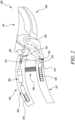
- FIG. 2 illustrates the power-assisted cutting tool 100 in an actuated state, in accordance with an embodiment of the present invention.
- the user interface 140 includes a hall sensor 140, spring 142 and a magnet 144 to measure the hand force applied by the user. This makes operation of the power-assisted cutting tool 100 more precise and dependent upon user profiles/dynamics (i.e. the hand force applied).
- the spring 142 and the magnet 144 change their relative positions with respect to the hall sensor 140 on sensing the hand force by the user as depicted here, in comparison to FIG. 1 .
- the cutting tool 100 may include sensors in addition or alternatively to the hall sensor 140, spring 142 and the magnet 144 to gauge/measure data relevant to the user for more efficient operation of the cutting tool 100.
- the cutting tool 100 may include sensors such as, but not limited to, displacement sensor, force sensor, vitals sensor (heartbeat etc.) which may communicate with the controller 170 to further optimize the operation of the cutting tool 100 as per the user or for any other consideration.
- the drive unit 170 includes a motor 150, a gearbox 160 and a clutch 170 and wire 172 arrangement to selectively provide the supplemental motor force. This arrangement ensures a smooth and safe application of the supplemental motor force to assist in operation of the power-assisted cutting tool 100. Further, the drive unit 170 is actuated to supply the supplemental motor force when the hand force measured by the user interface 140 is above a threshold value. When the drive unit 170 is actuated, the motor 150 starts working to actuate the clutch 170 in winding the wire 172 such that the wire 172 works to pull the first handle 112 towards the second handle 132, by a magnitude in equivalent to the supplemental motor force and thereby assisting the user in the cutting action.
- the threshold value may be user selected and/or user-centric to make the power-assisted cutting tool 100 applicable for various users, from a child to old age individuals.
- the cutting tool 100 includes a means (such as a button, knob, or switch, not shown) to activate or deactivate the drive unit 170.
- the drive unit 170 may be deactivated for instances which may require to save/extend battery life or allow uninterrupted operation of the power-assisted cutting tool 100 for low battery conditions. In such instances of the deactivated drive unit 170, the motor 150 will remain in a disengaged state leading to a purely user-based cutting action by the cutting tool 100, without any supplemental motor force.
- the first cutting element 110 and the second cutting element 130 are biased by a biasing spring 180, which ensures that the first cutting element 110 and the second cutting element 130, and the first handle 112 and the second handle 132 respectively, move to their original position in absence of any external force.
- the biasing spring 180 biases the first handle 112 to move away from the second handle 132 (say after end of the cutting action) and towards its original position which was the relative position of the first handle 112 and the second handle 132 before start of the cutting action.
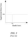
- FIG. 3 shows a graphical representation for supplemental motor force provided for a use scenario of a conventional power-assisted cutting tool (not shown) as known in prior art.
- the graph depicts a scenario where the supplemental motor force has a constant maximum value SMF 0 , when the hand force applied (by the user) is more than the threshold HF 0 .
- the conventional power-assisted cutting tool may be so configured that a driving means (say similar to the drive unit 170 of the present disclosure) actuates only when the hand force is more than the threshold HF 0 .
- the drive force reaches the threshold HF 0 , it is supplemented by the constant maximum value SMF 0 .
- Such a setting of the conventional power-assisted cutting tool, with the constant maximum value SMF 0 may be relevant for experienced users who may prefer to utilize the hand power initially and then only desire the hand force to be supplemented by a pre-set magnitude of the supplemental motor force i.e. the constant maximum value SMF 0 , in accordance with representation shown in latest figure.
- Such a setting may cause jerk or discomfort for a user due to sudden supply of power and may not be desirable.
- FIG. 4 a to 4 h shows graphical representations for supplemental motor force provided for different use scenarios of the power-assisted cutting tool 100, in accordance with embodiments of the present invention.
- the graphical representations depict different scenarios plotting the hand force along the x-axis while the supplemental motor force is along the y-axis.
- FIGS. 4 a, b illustrate scenarios where the hand force and the supplemental motor force share a linear relationship.
- the hand force applied is directly proportional to the supplemental motor force applied by the drive unit 170 as per FIG. 4 a.
- FIG. 4 a may find relevance where a user (say a child, old age individuals etc.) will expect assistance by the supplemental motor force throughout and from beginning of the cutting action.
- the cutting tool 100 may be so configured that the drive unit 170 actuates only when the hand force is more than a threshold HF 0 .
- This provision of the threshold HF 0 may find more relevance where the user may be expected to utilize the hand power and only make use of the supplemental motor force, after the threshold HF 0 from consideration such as saving battery use/status or for any other reason.
- FIGS. 4 c, d the graphs depict scenarios where the hand force and the supplemental motor force share a non-linear relationship.
- the hand force applied needs to be supplemented by a substantially larger magnitude of the supplemental motor force applied by the drive unit 170 as per the present figures.
- FIG. 4 c may find relevance where a user (say a child, old age individuals etc.) will expect assistance by a high magnitude of the supplemental motor force throughout and from beginning of the cutting action.
- the cutting tool 100 may be so configured that the drive unit 170 actuates only when the hand force is more than a threshold HF 0 .
- This provision of the threshold HF 0 may find more relevance where the user force may be more expected and would prefer to utilize the hand power initially and then the hand force may be later supplemented by a comparatively larger magnitude of the supplemental motor force, in accordance with representation shown in FIG. 4 d.
- FIG. 4 d may be utilized to save battery life/power or any other consideration, so that the motor 150 comes into picture only after the threshold is reached by the hand force, to be supplemented by the supplemental motor force.
- the curve shown is illustrated as a parabolic curve. However, it should be contemplated that any other such non-linear relationship may also be observed without limiting the scope of the present disclosure. For example, a hyperbolic curve, a partially elliptical curve, or a combination of plurality of curves may also be envisioned.
- FIGS. 4 e to 4 h the graphs depict scenarios where cutting takes place only post application of a threshold value of the hand force along with a constant maximum value SMF 0 of the supplemental motor force.
- multiple scenarios have been contemplated, starting from FIGS. 4 e, 4 f where the supplemental motor force is linearly proportional and non-linearly proportional with respect to the hand force, respectively.
- Such scenarios may be applicable for high force/intensity cutting or with users requiring substantial assistance form the drive unit 170, for the supplemental motor force.
- the next figures depict how the cutting tool 100 may be configured such that the drive unit 170 and the controller 190 are pre-set that after a lapse of a fixed time ( T1 , T2 for FIGS. 4 g, h respectively, or a pre-set amount of the supplemental motor force or battery power and the like) of the cutting action, the supplemental motor force becomes constant SCF 1 , SCF 2 for FIGS.
Landscapes
- Life Sciences & Earth Sciences (AREA)
- Forests & Forestry (AREA)
- Engineering & Computer Science (AREA)
- Mechanical Engineering (AREA)
- Biodiversity & Conservation Biology (AREA)
- Ecology (AREA)
- Environmental Sciences (AREA)
- Sawing (AREA)
- Surgical Instruments (AREA)
- Scissors And Nippers (AREA)
- Portable Power Tools In General (AREA)
Abstract
Description
- The present disclosure relates to cutting tools such as secateurs. More specifically, the present disclosure relates to a cutting tool with a power-assistance feature for an easy and safe cutting action catering to different user profiles.
- Cutting tools such as secateurs are used for performing cutting action for garden applications which may involve different cutting force for different branches and the like. Lately there have been increasing demand for power-assisted secateurs, since such tools provide ease of cutting as compared to some old and conventional cutting tools. Such secateurs also sometime have some features to save operators from any risky operation during performing cutting action.
- However, there may be instances where such power-assisted secateurs may pose certain risks in case of undesirably fast, and instant powering of the power-assisted secateurs. From implementation benefits, there is a need for a more balanced and user-centric powering of power-assisted secateurs such that they provide required cutting force without hampering user-safety and the like.
- An example of a cutting tool is provided by
EP3081075 (hereinafter referred to as '075 reference). The '075 reference discloses a cutting device having a first cutting element and a second cutting element which are movable relative to one another. Further, a drive unit is provided in at least one operating state for movement of the second cutting element relative to the first cutting element. Moreover, the cutting device includes a self-switching coupling unit which deactivates or decoupled the drive unit, in the operating state. However, the '075 reference comes short of a provision to provide a smooth and safe operation with user-based power assistance. - Thus, there is a need of an improved cutting tool which allows ease of operation such as cutting by different individuals who may selectively desire assistance during some cutting applications.
- In view of the above, it is an objective of the present invention to solve or at least reduce the drawbacks discussed above. The objective is at least partially achieved by a power-assisted cutting tool. The power-assisted cutting tool includes a first cutting element. The power-assisted cutting tool includes a second cutting element pivotally coupled to the first cutting element. The first cutting element and the second cutting element together perform a cutting action on an object placed between them. The power-assisted cutting tool includes a drive unit operatively coupled to at least one of the first cutting element and the second cutting element. Further, the drive unit selectively provides a supplemental motor force to assist a movement of at least one of the first cutting element and the second cutting element to perform the cutting action. Moreover, the power-assisted cutting tool includes a user interface to measure a hand force applied by a user, and generate a signal indicative of the measured hand force. And, the power-assisted cutting tool includes a controller communicably coupled to the user interface and the drive unit, where the controller receives the signal indicative of the measured hand force and actuate the drive unit based on the received signal. Further, the controller adjusts the operation of the drive unit to provide the supplemental motor force based on the measured hand force. The power-assisted cutting tool is characterized in that the controller actuates the drive unit such that a magnitude of the supplemental motor force is at least one of a continuous variable configured to attain a plurality of different values within a pre-determined force range when the drive unit is assisting the movement of at least one of the first cutting element and the second cutting element to perform the cutting action. Alternatively, the magnitude of the supplemental motor force is at least one of a discreet variable configured to attain a plurality of different values within a pre-determined force range when the drive unit is assisting the movement of at least one of the first cutting element and the second cutting element to perform the cutting action. Thus, the present disclosure provides a simple, efficient, and user-friendly cutting tool which ensures desired power-assistance to a user.
- According to an embodiment of the present invention, the user interface includes a hall sensor and a magnet to measure the hand force applied by the user. This makes operation of the power-assisted cutting tool more precise and dependent upon user dynamics (i.e. the hand force applied).
- According to an embodiment of the present invention, the drive unit includes a motor, a gearbox and a clutch and wire arrangement to selectively provide the supplemental motor force. This arrangement ensures a smooth and safe application of the supplemental motor force to assist in operation of the power-assisted cutting tool.
- According to an embodiment of the present invention, the cutting tool includes a means to activate or deactivate the drive unit. Such a provision may be provided to cater to save/extend battery life or allow uninterrupted operation of the power-assisted cutting tool for low battery conditions.
- According to an embodiment of the present invention, the drive unit is actuated to supply the supplemental motor force when the hand force measured by the user interface is above a threshold value. The threshold value may be user selected and/or user-centric to make the power-assisted cutting tool applicable for various users, from a child to old age individuals.
- According to an embodiment of the present invention, the first cutting element and the second cutting element are biased by a biasing spring, which ensures that the first cutting element and the second cutting element move to their original position in absence of any external force.
- Other features and aspects of this invention will be apparent from the following description and the accompanying drawings.
- The invention will be described in more detail with reference to the enclosed drawings, wherein:
-
FIG. 1 shows a schematic view of a power-assisted cutting tool, in accordance with an embodiment of the present invention; -
FIG. 2 shows a schematic view of the power-assisted cutting tool in an actuated state, in accordance with an embodiment of the present invention; -
FIG. 3 shows a graphical representation for a use scenario of a conventional power-assisted cutting tool; as known in prior art; and -
FIGS. 4 a to 4 h show graphical representations for different use scenarios of the power-assisted cutting tool, in accordance with embodiments of the present invention. - The present invention will be described more fully hereinafter with reference to the accompanying drawings, in which example embodiments of the invention incorporating one or more aspects of the present invention are shown. This invention may, however, be embodied in many different forms and should not be construed as limited to the embodiments set forth herein; rather, these embodiments are provided so that this disclosure will be thorough and complete, and will fully convey the scope of the invention to those skilled in the art. For example, one or more aspects of the present invention can be utilized in other embodiments and even other types of structures and/or methods. In the drawings, like numbers refer to like elements.
- Certain terminology is used herein for convenience only and is not to be taken as a limitation on the invention. For example, "upper", "lower", "front", "rear", "side", "longitudinal", "lateral", "transverse", "upwards", "downwards", "forward", "backward", "sideward", "left," "right," "horizontal," "vertical," "upward", "inner", "outer", "inward", "outward", "top", "bottom", "higher", "above", "below", "central", "middle", "intermediate", "between", "end", "adjacent", "proximate", "near", "distal", "remote", "radial", "circumferential", or the like, merely describe the configuration shown in the Figures. Indeed, the components may be oriented in any direction and the terminology, therefore, should be understood as encompassing such variations unless specified otherwise.
- In the drawings and specification, there have been disclosed preferred embodiments and examples of the invention and, although specific terms are employed, they are used in a generic and descriptive sense only and not for the purpose of limitation of the scope of the invention being set forth in the following claims.
-
FIG. 1 illustrates a power-assistedcutting tool 100. The power-assistedcutting tool 100 of the present disclosure is illustrated as a secateur, however, the present disclosure may be readily applied to anycutting tool 100 such as, but not limited to, a lopper, shear, scissor etc. with two or more cutting edges. The power-assistedcutting tool 100 includes afirst cutting element 110 attached to afirst handle 112. The power-assistedcutting tool 100 includes asecond cutting element 130 attached to asecond handle 132. Further, thesecond cutting element 130 is pivotally coupled to thefirst cutting element 110 at apivot 120. Thefirst cutting element 110 and thesecond cutting element 130 together perform a cutting action on an object (such as a branch, not shown) placed between them. - The power-assisted
cutting tool 100 includes adrive unit 170 operatively coupled to at least one of thefirst cutting element 110 and thesecond cutting element 130. In an embodiment, thedrive unit 170 is operatively coupled to thefirst cutting element 110 only. In an embodiment, thedrive unit 170 is operatively coupled to thesecond cutting element 130 only. In another embodiment, thedrive unit 170 is operatively coupled to both thefirst cutting element 110 and thesecond cutting element 130. The present disclosure illustrates thedrive unit 170 powered by asecond battery 152 housed within thesecond handle 132. However, thedrive unit 170 may be housed anywhere within thecutting tool 100 and all such variations have been contemplated and are well within the scope of the present disclosure. Further, thedrive unit 170 selectively provides asupplemental motor 150 force to assist a movement of at least one of thefirst cutting element 110 and thesecond cutting element 130 to perform the cutting action. - Moreover, the power-assisted
cutting tool 100 includes auser interface 140 to measure a hand force applied by a user, and generate a signal indicative of the measured hand force. Theuser interface 140 is powered by afirst battery 146 housed within thefirst handle 112. And, the power-assistedcutting tool 100 includes acontroller 190 communicably coupled to theuser interface 140 and thedrive unit 170, as illustrated by dashed lines inFIGS. 1 ,2 . Thecontroller 190 receives the signal indicative of the measured hand force and actuates thedrive unit 170 based on the received signal. As illustrated, thecontroller 190 is shown housed within thesecond handle 132, however it may be housed anywhere within thecutting tool 100, as will be evident to a person having ordinary knowledge in the art. - Further, the
controller 190 adjusts the operation of thedrive unit 170 to provide the supplemental motor force based on the measured hand force. In some embodiments, thecontroller 190, theuser interface 140, and thedrive unit 170 may be powered by any or both of thefirst battery 146, thesecond battery 152 depending upon implementation needs (say run time, service life and the like) of thecutting tool 100. Moreover, the user of the cutting tool may be prompted status(es) of thefirst battery 146, the second battery 152 (alternatively referred to as a battery hereinafter) during powering by the supplemental motor force or while configuring of thecutting tool 100 by the user for any desired working profile of thecutting tool 100 as explained in more details later inFIGS. 4a to 4h . - The power-assisted
cutting tool 100 is configured such that thecontroller 190 actuates thedrive unit 170 to provide the supplemental motor force. The supplemental motor force is provided such that a magnitude of the supplemental motor force is at least one of a continuous variable and a discreet variable. In an embodiment, the supplemental motor force is a continuous variable to attain a plurality of different values within a pre-determined force range when thedrive unit 170 is assisting the movement of at least one of thefirst cutting element 110 and thesecond cutting element 130 to perform the cutting action. The pre-determined force range may be defined between an upper limit and a lower limit. Magnitude of the supplemental motor force as a continuous variable may vary between the upper limit and the lower limit attaining any value therebetween. Magnitude of the supplemental motor force may remain constant or vary between plurality of values based on application requirements. - In another embodiment, the supplemental motor force is a discreet variable to attain a plurality of different values within a pre-determined force range when the
drive unit 170 is assisting the movement of at least one of thefirst cutting element 110 and thesecond cutting element 130 to perform the cutting action. The pre-determined force range may be defined between an upper limit and a lower limit. Magnitude of the supplemental motor force as a discreet variable may vary between the upper limit and the lower limit attaining discreet values therebetween. Magnitude of the supplemental motor force may remain constant or vary between plurality of values based on application requirements. -
FIG. 2 illustrates the power-assistedcutting tool 100 in an actuated state, in accordance with an embodiment of the present invention. Theuser interface 140 includes ahall sensor 140,spring 142 and amagnet 144 to measure the hand force applied by the user. This makes operation of the power-assistedcutting tool 100 more precise and dependent upon user profiles/dynamics (i.e. the hand force applied). Here it is worth noting that thespring 142 and themagnet 144 change their relative positions with respect to thehall sensor 140 on sensing the hand force by the user as depicted here, in comparison toFIG. 1 . Further, thecutting tool 100 may include sensors in addition or alternatively to thehall sensor 140,spring 142 and themagnet 144 to gauge/measure data relevant to the user for more efficient operation of thecutting tool 100. For instance, thecutting tool 100 may include sensors such as, but not limited to, displacement sensor, force sensor, vitals sensor (heartbeat etc.) which may communicate with thecontroller 170 to further optimize the operation of thecutting tool 100 as per the user or for any other consideration. - In an embodiment, the
drive unit 170 includes amotor 150, agearbox 160 and a clutch 170 andwire 172 arrangement to selectively provide the supplemental motor force. This arrangement ensures a smooth and safe application of the supplemental motor force to assist in operation of the power-assistedcutting tool 100. Further, thedrive unit 170 is actuated to supply the supplemental motor force when the hand force measured by theuser interface 140 is above a threshold value. When thedrive unit 170 is actuated, themotor 150 starts working to actuate the clutch 170 in winding thewire 172 such that thewire 172 works to pull thefirst handle 112 towards thesecond handle 132, by a magnitude in equivalent to the supplemental motor force and thereby assisting the user in the cutting action. The threshold value may be user selected and/or user-centric to make the power-assistedcutting tool 100 applicable for various users, from a child to old age individuals. - In an embodiment, the
cutting tool 100 includes a means (such as a button, knob, or switch, not shown) to activate or deactivate thedrive unit 170. Thedrive unit 170 may be deactivated for instances which may require to save/extend battery life or allow uninterrupted operation of the power-assistedcutting tool 100 for low battery conditions. In such instances of the deactivateddrive unit 170, themotor 150 will remain in a disengaged state leading to a purely user-based cutting action by thecutting tool 100, without any supplemental motor force. - In an embodiment, the
first cutting element 110 and thesecond cutting element 130 are biased by a biasingspring 180, which ensures that thefirst cutting element 110 and thesecond cutting element 130, and thefirst handle 112 and thesecond handle 132 respectively, move to their original position in absence of any external force. Put simply, the biasingspring 180 biases thefirst handle 112 to move away from the second handle 132 (say after end of the cutting action) and towards its original position which was the relative position of thefirst handle 112 and thesecond handle 132 before start of the cutting action. -
FIG. 3 shows a graphical representation for supplemental motor force provided for a use scenario of a conventional power-assisted cutting tool (not shown) as known in prior art. As illustrated, the graph depicts a scenario where the supplemental motor force has a constant maximum value SMF0, when the hand force applied (by the user) is more than the threshold HF0. For implementation, the conventional power-assisted cutting tool may be so configured that a driving means (say similar to thedrive unit 170 of the present disclosure) actuates only when the hand force is more than the threshold HF0. When the drive force reaches the threshold HF0 , it is supplemented by the constant maximum value SMF0 . Such a setting of the conventional power-assisted cutting tool, with the constant maximum value SMF0 may be relevant for experienced users who may prefer to utilize the hand power initially and then only desire the hand force to be supplemented by a pre-set magnitude of the supplemental motor force i.e. the constant maximum value SMF0 , in accordance with representation shown in latest figure. Such a setting may cause jerk or discomfort for a user due to sudden supply of power and may not be desirable. -
FIG. 4 a to 4 h shows graphical representations for supplemental motor force provided for different use scenarios of the power-assistedcutting tool 100, in accordance with embodiments of the present invention. The graphical representations depict different scenarios plotting the hand force along the x-axis while the supplemental motor force is along the y-axis. - For instance,
FIGS. 4 a, b illustrate scenarios where the hand force and the supplemental motor force share a linear relationship. Put simply, the hand force applied is directly proportional to the supplemental motor force applied by thedrive unit 170 as perFIG. 4 a. So,FIG. 4 a may find relevance where a user (say a child, old age individuals etc.) will expect assistance by the supplemental motor force throughout and from beginning of the cutting action. In another similar instance, thecutting tool 100 may be so configured that thedrive unit 170 actuates only when the hand force is more than a threshold HF0 . This provision of the threshold HF0 may find more relevance where the user may be expected to utilize the hand power and only make use of the supplemental motor force, after the threshold HF0 from consideration such as saving battery use/status or for any other reason. - Referring to,
FIGS. 4 c, d , the graphs depict scenarios where the hand force and the supplemental motor force share a non-linear relationship. As illustrated, the hand force applied needs to be supplemented by a substantially larger magnitude of the supplemental motor force applied by thedrive unit 170 as per the present figures. In particular,FIG. 4 c may find relevance where a user (say a child, old age individuals etc.) will expect assistance by a high magnitude of the supplemental motor force throughout and from beginning of the cutting action. In another similar instance, thecutting tool 100 may be so configured that thedrive unit 170 actuates only when the hand force is more than a threshold HF0 . This provision of the threshold HF0 may find more relevance where the user force may be more expected and would prefer to utilize the hand power initially and then the hand force may be later supplemented by a comparatively larger magnitude of the supplemental motor force, in accordance with representation shown inFIG. 4 d. Again,FIG. 4 d may be utilized to save battery life/power or any other consideration, so that themotor 150 comes into picture only after the threshold is reached by the hand force, to be supplemented by the supplemental motor force. The curve shown is illustrated as a parabolic curve. However, it should be contemplated that any other such non-linear relationship may also be observed without limiting the scope of the present disclosure. For example, a hyperbolic curve, a partially elliptical curve, or a combination of plurality of curves may also be envisioned. - Now referring to
FIGS. 4 e to 4 h , the graphs depict scenarios where cutting takes place only post application of a threshold value of the hand force along with a constant maximum value SMF0 of the supplemental motor force. Hereafter multiple scenarios have been contemplated, starting fromFIGS. 4 e, 4 f where the supplemental motor force is linearly proportional and non-linearly proportional with respect to the hand force, respectively. Such scenarios may be applicable for high force/intensity cutting or with users requiring substantial assistance form thedrive unit 170, for the supplemental motor force. Choice of the linear (FIG. 4 e) or non-linear (FIG. 4 f) relationship may be based on user profile, namely factors such as user experience, cutting force requirement, battery life, cuttingtool 100 service life or any other user based parameter as will be evident to a person having knowledge in the relevant art. Building onFIG. 4 e , the next figures depict how thecutting tool 100 may be configured such that thedrive unit 170 and thecontroller 190 are pre-set that after a lapse of a fixed time (T1, T2 forFIGS. 4 g, h respectively, or a pre-set amount of the supplemental motor force or battery power and the like) of the cutting action, the supplemental motor force becomes constant SCF1 , SCF2 forFIGS. 4 g, h respectively, even though the hand force may continue to increase till end of the cutting action takes place, in accordance with representation shown inFIGS. 4 g, h . These scenarios have been contemplated to save any excessive draining and working up of themotor 150 and thedrive unit 170 and thereby to work as a virtual fail-safe of the power-assistedcutting tool 100. Further, it should be contemplated that the various scenarios depicted throughFIG. 4 a toFIG. 4 h are exemplary in nature. Various combinations of these examples, as well as various other graphical relationships may also be envisioned based on application requirements and the present disclosure is not limited by any such curves. - In the drawings and specification, there have been disclosed preferred embodiments and examples of the invention and, although specific terms are employed, they are used in a generic and descriptive sense only and not for the purpose of limitation of the scope of the invention being set forth in the following claims.
-
- 100
- Power-Assisted Cutting Tool
- 110
- First Cutting Element
- 112
- First Handle
- 120
- Pivot
- 130
- Second Cutting Element
- 132
- Second Handle
- 140
- User Interface/Hall Sensor
- 142
- Spring
- 144
- Magnet
- 146
- First Battery
- 150
- Motor
- 152
- Second Battery
- 160
- Gearbox
- 170
- Drive Unit/Clutch
- 172
- Wire
- 180
- Biasing Spring
- 190
- Controller
Claims (6)
- A power-assisted cutting tool (100) comprising:a first cutting element (110);a second cutting element (130) pivotally coupled to the first cutting element (110), wherein the first cutting element (110) and the second cutting element (130) together perform a cutting action on an object placed therebetween;a drive unit (170) operatively coupled to at least one of the first cutting element (110) and the second cutting element (130), wherein the drive unit (170) is configured to selectively provide a supplemental motor (150) force to assist a movement of at least one of the first cutting element (110) and the second cutting element (130) to perform the cutting action;a user interface (140) configured to measure a hand force applied by a user, and generate a signal indicative of the measured hand force; anda controller (190) communicably coupled to the user interface (140) and the drive unit (170), wherein the controller (190) is configured to receive the signal indicative of the measured hand force and actuate the drive unit (170) based on the received signal;wherein the controller (190) is configured to adjust the operation of the drive unit (170) to provide the supplemental motor (150) force based on the measured hand force; andwherein the controller (190) actuates the drive unit (170) such that a magnitude of the supplemental motor (150) force is at least one ofa continuous variable configured to attain a plurality of different values within a pre-determined force range when the drive unit (170) is assisting the movement of at least one of the first cutting element (110) and the second cutting element (130) to perform the cutting action; anda discreet variable configured to attain a plurality of different values within a pre-determined force range when the drive unit (170) is assisting the movement of at least one of the first cutting element (110) and the second cutting element (130) to perform the cutting action;characterized in that:
the cutting tool (100) is configured such that the drive unit (170) and the controller (190) are pre-set that after a lapse of time or a pre-set amount of the supplemental motor force or battery power of the cutting action, the supplemental motor force becomes constant. - The power-assisted cutting tool (100) of claim 1, wherein the user interface (140) includes a hall sensor (140) and a magnet (144) to measure the hand force applied by the user.
- The power-assisted cutting tool (100) of claim 1, wherein the drive unit (170) includes a motor (150), a gearbox (160) and a clutch (170) and wire (172) arrangement to selectively provide the supplemental motor (150) force.
- The power-assisted cutting tool (100) of claim 1, wherein the cutting tool (100) includes a means to activate or deactivate the drive unit (170).
- The power-assisted cutting tool (100) of claim 1, wherein the drive unit (170) is actuated to supply the supplemental motor (150) force when the hand force measured by the user interface (140) is above a threshold value.
- The power-assisted cutting tool (100) of claim 1, wherein the first cutting element (110) and the second cutting element (130) are biased by a biasing spring (180), which ensures that the first cutting element (110) and the second cutting element (130) move to their original position in absence of any external force.
Applications Claiming Priority (3)
| Application Number | Priority Date | Filing Date | Title |
|---|---|---|---|
| DE102019003846 | 2019-06-03 | ||
| EP19831997.2A EP3976325B1 (en) | 2019-06-03 | 2019-12-11 | Power-assisted cutting tool |
| PCT/EP2019/084654 WO2020244794A1 (en) | 2019-06-03 | 2019-12-11 | Power-assisted cutting tool |
Related Parent Applications (3)
| Application Number | Title | Priority Date | Filing Date |
|---|---|---|---|
| PCT/EP2019/084654 Previously-Filed-Application WO2020244794A1 (en) | 2019-06-03 | 2019-12-11 | Power-assisted cutting tool |
| EP19831997.2A Division EP3976325B1 (en) | 2019-06-03 | 2019-12-11 | Power-assisted cutting tool |
| EP19831997.2A Division-Into EP3976325B1 (en) | 2019-06-03 | 2019-12-11 | Power-assisted cutting tool |
Publications (3)
| Publication Number | Publication Date |
|---|---|
| EP4245122A2 true EP4245122A2 (en) | 2023-09-20 |
| EP4245122A3 EP4245122A3 (en) | 2023-10-18 |
| EP4245122B1 EP4245122B1 (en) | 2024-05-29 |
Family
ID=69105769
Family Applications (2)
| Application Number | Title | Priority Date | Filing Date |
|---|---|---|---|
| EP23169055.3A Active EP4245122B1 (en) | 2019-06-03 | 2019-12-11 | Power-assisted cutting tool |
| EP19831997.2A Active EP3976325B1 (en) | 2019-06-03 | 2019-12-11 | Power-assisted cutting tool |
Family Applications After (1)
| Application Number | Title | Priority Date | Filing Date |
|---|---|---|---|
| EP19831997.2A Active EP3976325B1 (en) | 2019-06-03 | 2019-12-11 | Power-assisted cutting tool |
Country Status (6)
| Country | Link |
|---|---|
| EP (2) | EP4245122B1 (en) |
| CN (1) | CN113924197A (en) |
| FI (2) | FI3976325T3 (en) |
| PL (2) | PL4245122T3 (en) |
| TW (1) | TWI842906B (en) |
| WO (1) | WO2020244794A1 (en) |
Families Citing this family (3)
| Publication number | Priority date | Publication date | Assignee | Title |
|---|---|---|---|---|
| US10172292B2 (en) | 2016-10-17 | 2019-01-08 | Robert Bosch Gmbh | Cutting device |
| EP4052564A1 (en) * | 2021-03-05 | 2022-09-07 | Husqvarna Ab | Cutting tool |
| US12589512B2 (en) * | 2023-12-28 | 2026-03-31 | Toyota Motor Engineering & Manufacturing North America, Inc. | Shearing tool with closure assist |
Citations (1)
| Publication number | Priority date | Publication date | Assignee | Title |
|---|---|---|---|---|
| EP3081075A1 (en) | 2015-04-17 | 2016-10-19 | Robert Bosch GmbH | Cutting device |
Family Cites Families (8)
| Publication number | Priority date | Publication date | Assignee | Title |
|---|---|---|---|---|
| JP2001178848A (en) * | 1999-12-24 | 2001-07-03 | Sanshiro Takamiya | Apparatus for improving function of wrist |
| JP5332662B2 (en) * | 2009-01-30 | 2013-11-06 | マックス株式会社 | Electric scissors |
| DE102010016296B4 (en) * | 2010-04-01 | 2012-05-03 | AR&T, Applied Robot & Technologies UG (haftungsbeschränkt) | Auxiliary power operated scissors and method of operation thereof |
| CN201754179U (en) * | 2010-07-15 | 2011-03-02 | 华南理工大学 | Clamp type magnetic flux detecting probe |
| CH710461A1 (en) * | 2014-12-11 | 2016-06-15 | Spanset Inter Ag | Apparatus and method for measuring the tensile stress in a tension belt. |
| US9766142B1 (en) * | 2015-03-20 | 2017-09-19 | Cory S. Hague | Magnetic force sensor systems and methods |
| DE102016211974B4 (en) * | 2016-06-30 | 2024-10-17 | Robert Bosch Gmbh | cutting device |
| CN206416169U (en) * | 2017-01-17 | 2017-08-18 | 慧灵科技(深圳)有限公司 | A kind of electric claw with force feedback mechanism and accurate control gripping power |
-
2019
- 2019-12-11 FI FIEP19831997.2T patent/FI3976325T3/en active
- 2019-12-11 EP EP23169055.3A patent/EP4245122B1/en active Active
- 2019-12-11 PL PL23169055.3T patent/PL4245122T3/en unknown
- 2019-12-11 WO PCT/EP2019/084654 patent/WO2020244794A1/en not_active Ceased
- 2019-12-11 CN CN201980097127.0A patent/CN113924197A/en active Pending
- 2019-12-11 FI FIEP23169055.3T patent/FI4245122T3/en active
- 2019-12-11 EP EP19831997.2A patent/EP3976325B1/en active Active
- 2019-12-11 PL PL19831997.2T patent/PL3976325T3/en unknown
-
2020
- 2020-06-02 TW TW109118491A patent/TWI842906B/en active
Patent Citations (1)
| Publication number | Priority date | Publication date | Assignee | Title |
|---|---|---|---|---|
| EP3081075A1 (en) | 2015-04-17 | 2016-10-19 | Robert Bosch GmbH | Cutting device |
Also Published As
| Publication number | Publication date |
|---|---|
| TWI842906B (en) | 2024-05-21 |
| WO2020244794A1 (en) | 2020-12-10 |
| EP4245122B1 (en) | 2024-05-29 |
| FI3976325T3 (en) | 2023-10-06 |
| EP3976325A1 (en) | 2022-04-06 |
| TW202044981A (en) | 2020-12-16 |
| FI4245122T3 (en) | 2024-06-28 |
| PL4245122T3 (en) | 2024-07-22 |
| CN113924197A (en) | 2022-01-11 |
| PL3976325T3 (en) | 2023-12-04 |
| EP4245122A3 (en) | 2023-10-18 |
| EP3976325B1 (en) | 2023-08-23 |
Similar Documents
| Publication | Publication Date | Title |
|---|---|---|
| EP3976325B1 (en) | Power-assisted cutting tool | |
| US11185956B2 (en) | Force responsive power tool | |
| AU2020200319B2 (en) | Systems and methods for configuring a reciprocating saw | |
| EP3155887B1 (en) | Power tool and control method thereof | |
| CN105605210B (en) | The velocity variations method of the change control system of walk-behind working machine and the working rig | |
| US20120169256A1 (en) | Electric power tool | |
| EP1247687A3 (en) | Control apparatus for electric motor and control apparatus for hybrid vehicle | |
| US9577567B2 (en) | Method for operating a work apparatus having an electric motor | |
| US10994403B2 (en) | Hand-held power tool comprising a gearshift unit | |
| EP2685627A2 (en) | Voltage increasing control circuit and power tool | |
| US20150083448A1 (en) | Electric tool and method for fastening a threaded member by using it | |
| BR112017007570B1 (en) | PROCESS AND CONTROL DEVICE FOR EQUIPMENT WITH MOTOR AND PORTABLE POWER TOOL | |
| JP6226420B2 (en) | Scissors with electric assist function | |
| EP2779413A2 (en) | Drive system and method for driving a vehicle | |
| CA2921744C (en) | Tactile feel control device | |
| CN106541372A (en) | Electric tool and its method using travel switch controlled motor rotating speed | |
| CN106385938A (en) | Lawn mower | |
| CN104723290A (en) | Control device and control method for torsion output of electric tool | |
| JP2020000064A (en) | Rice transplanter | |
| US9726729B2 (en) | Method for controlling electric motor by trigger | |
| CN115245087B (en) | Back-walking self-pushing working machine | |
| CN105210542B (en) | United reaper manipulation device | |
| CN105075688A (en) | A cutting tool capable of intelligently judging closing and providing assistance | |
| CN206111745U (en) | Linked system and engineering machine tool | |
| JP2020131411A (en) | Robot control system |
Legal Events
| Date | Code | Title | Description |
|---|---|---|---|
| PUAI | Public reference made under article 153(3) epc to a published international application that has entered the european phase |
Free format text: ORIGINAL CODE: 0009012 |
|
| STAA | Information on the status of an ep patent application or granted ep patent |
Free format text: STATUS: THE APPLICATION HAS BEEN PUBLISHED |
|
| REG | Reference to a national code |
Ref country code: DE Ref legal event code: R079 Free format text: PREVIOUS MAIN CLASS: A01G0003037000 Ipc: B26B0015000000 Ref country code: DE Ref legal event code: R079 Ref document number: 602019053148 Country of ref document: DE Free format text: PREVIOUS MAIN CLASS: A01G0003037000 Ipc: B26B0015000000 |
|
| PUAL | Search report despatched |
Free format text: ORIGINAL CODE: 0009013 |
|
| AC | Divisional application: reference to earlier application |
Ref document number: 3976325 Country of ref document: EP Kind code of ref document: P |
|
| AK | Designated contracting states |
Kind code of ref document: A2 Designated state(s): AL AT BE BG CH CY CZ DE DK EE ES FI FR GB GR HR HU IE IS IT LI LT LU LV MC MK MT NL NO PL PT RO RS SE SI SK SM TR |
|
| AK | Designated contracting states |
Kind code of ref document: A3 Designated state(s): AL AT BE BG CH CY CZ DE DK EE ES FI FR GB GR HR HU IE IS IT LI LT LU LV MC MK MT NL NO PL PT RO RS SE SI SK SM TR |
|
| RIC1 | Information provided on ipc code assigned before grant |
Ipc: A01G 3/037 20060101ALI20230908BHEP Ipc: B26B 15/00 20060101AFI20230908BHEP |
|
| STAA | Information on the status of an ep patent application or granted ep patent |
Free format text: STATUS: REQUEST FOR EXAMINATION WAS MADE |
|
| 17P | Request for examination filed |
Effective date: 20231023 |
|
| RBV | Designated contracting states (corrected) |
Designated state(s): AL AT BE BG CH CY CZ DE DK EE ES FI FR GB GR HR HU IE IS IT LI LT LU LV MC MK MT NL NO PL PT RO RS SE SI SK SM TR |
|
| GRAP | Despatch of communication of intention to grant a patent |
Free format text: ORIGINAL CODE: EPIDOSNIGR1 |
|
| STAA | Information on the status of an ep patent application or granted ep patent |
Free format text: STATUS: GRANT OF PATENT IS INTENDED |
|
| INTG | Intention to grant announced |
Effective date: 20231205 |
|
| GRAS | Grant fee paid |
Free format text: ORIGINAL CODE: EPIDOSNIGR3 |
|
| P01 | Opt-out of the competence of the unified patent court (upc) registered |
Effective date: 20231219 |
|
| GRAA | (expected) grant |
Free format text: ORIGINAL CODE: 0009210 |
|
| STAA | Information on the status of an ep patent application or granted ep patent |
Free format text: STATUS: THE PATENT HAS BEEN GRANTED |
|
| AC | Divisional application: reference to earlier application |
Ref document number: 3976325 Country of ref document: EP Kind code of ref document: P |
|
| AK | Designated contracting states |
Kind code of ref document: B1 Designated state(s): AL AT BE BG CH CY CZ DE DK EE ES FI FR GB GR HR HU IE IS IT LI LT LU LV MC MK MT NL NO PL PT RO RS SE SI SK SM TR |
|
| REG | Reference to a national code |
Ref country code: CH Ref legal event code: EP |
|
| REG | Reference to a national code |
Ref country code: IE Ref legal event code: FG4D |
|
| REG | Reference to a national code |
Ref country code: DE Ref legal event code: R096 Ref document number: 602019053148 Country of ref document: DE |
|
| REG | Reference to a national code |
Ref country code: FI Ref legal event code: FGE |
|
| REG | Reference to a national code |
Ref country code: LT Ref legal event code: MG9D |
|
| REG | Reference to a national code |
Ref country code: NL Ref legal event code: MP Effective date: 20240529 |
|
| PG25 | Lapsed in a contracting state [announced via postgrant information from national office to epo] |
Ref country code: IS Free format text: LAPSE BECAUSE OF FAILURE TO SUBMIT A TRANSLATION OF THE DESCRIPTION OR TO PAY THE FEE WITHIN THE PRESCRIBED TIME-LIMIT Effective date: 20240929 |
|
| PG25 | Lapsed in a contracting state [announced via postgrant information from national office to epo] |
Ref country code: BG Free format text: LAPSE BECAUSE OF FAILURE TO SUBMIT A TRANSLATION OF THE DESCRIPTION OR TO PAY THE FEE WITHIN THE PRESCRIBED TIME-LIMIT Effective date: 20240529 |
|
| PG25 | Lapsed in a contracting state [announced via postgrant information from national office to epo] |
Ref country code: HR Free format text: LAPSE BECAUSE OF FAILURE TO SUBMIT A TRANSLATION OF THE DESCRIPTION OR TO PAY THE FEE WITHIN THE PRESCRIBED TIME-LIMIT Effective date: 20240529 |
|
| PG25 | Lapsed in a contracting state [announced via postgrant information from national office to epo] |
Ref country code: GR Free format text: LAPSE BECAUSE OF FAILURE TO SUBMIT A TRANSLATION OF THE DESCRIPTION OR TO PAY THE FEE WITHIN THE PRESCRIBED TIME-LIMIT Effective date: 20240830 |
|
| REG | Reference to a national code |
Ref country code: AT Ref legal event code: MK05 Ref document number: 1690259 Country of ref document: AT Kind code of ref document: T Effective date: 20240529 |
|
| PG25 | Lapsed in a contracting state [announced via postgrant information from national office to epo] |
Ref country code: ES Free format text: LAPSE BECAUSE OF FAILURE TO SUBMIT A TRANSLATION OF THE DESCRIPTION OR TO PAY THE FEE WITHIN THE PRESCRIBED TIME-LIMIT Effective date: 20240529 |
|
| PG25 | Lapsed in a contracting state [announced via postgrant information from national office to epo] |
Ref country code: AT Free format text: LAPSE BECAUSE OF FAILURE TO SUBMIT A TRANSLATION OF THE DESCRIPTION OR TO PAY THE FEE WITHIN THE PRESCRIBED TIME-LIMIT Effective date: 20240529 |
|
| PG25 | Lapsed in a contracting state [announced via postgrant information from national office to epo] |
Ref country code: LV Free format text: LAPSE BECAUSE OF FAILURE TO SUBMIT A TRANSLATION OF THE DESCRIPTION OR TO PAY THE FEE WITHIN THE PRESCRIBED TIME-LIMIT Effective date: 20240529 |
|
| PG25 | Lapsed in a contracting state [announced via postgrant information from national office to epo] |
Ref country code: NO Free format text: LAPSE BECAUSE OF FAILURE TO SUBMIT A TRANSLATION OF THE DESCRIPTION OR TO PAY THE FEE WITHIN THE PRESCRIBED TIME-LIMIT Effective date: 20240829 Ref country code: LV Free format text: LAPSE BECAUSE OF FAILURE TO SUBMIT A TRANSLATION OF THE DESCRIPTION OR TO PAY THE FEE WITHIN THE PRESCRIBED TIME-LIMIT Effective date: 20240529 Ref country code: IS Free format text: LAPSE BECAUSE OF FAILURE TO SUBMIT A TRANSLATION OF THE DESCRIPTION OR TO PAY THE FEE WITHIN THE PRESCRIBED TIME-LIMIT Effective date: 20240929 Ref country code: HR Free format text: LAPSE BECAUSE OF FAILURE TO SUBMIT A TRANSLATION OF THE DESCRIPTION OR TO PAY THE FEE WITHIN THE PRESCRIBED TIME-LIMIT Effective date: 20240529 Ref country code: GR Free format text: LAPSE BECAUSE OF FAILURE TO SUBMIT A TRANSLATION OF THE DESCRIPTION OR TO PAY THE FEE WITHIN THE PRESCRIBED TIME-LIMIT Effective date: 20240830 Ref country code: ES Free format text: LAPSE BECAUSE OF FAILURE TO SUBMIT A TRANSLATION OF THE DESCRIPTION OR TO PAY THE FEE WITHIN THE PRESCRIBED TIME-LIMIT Effective date: 20240529 Ref country code: BG Free format text: LAPSE BECAUSE OF FAILURE TO SUBMIT A TRANSLATION OF THE DESCRIPTION OR TO PAY THE FEE WITHIN THE PRESCRIBED TIME-LIMIT Effective date: 20240529 Ref country code: AT Free format text: LAPSE BECAUSE OF FAILURE TO SUBMIT A TRANSLATION OF THE DESCRIPTION OR TO PAY THE FEE WITHIN THE PRESCRIBED TIME-LIMIT Effective date: 20240529 Ref country code: RS Free format text: LAPSE BECAUSE OF FAILURE TO SUBMIT A TRANSLATION OF THE DESCRIPTION OR TO PAY THE FEE WITHIN THE PRESCRIBED TIME-LIMIT Effective date: 20240829 |
|
| PG25 | Lapsed in a contracting state [announced via postgrant information from national office to epo] |
Ref country code: NL Free format text: LAPSE BECAUSE OF FAILURE TO SUBMIT A TRANSLATION OF THE DESCRIPTION OR TO PAY THE FEE WITHIN THE PRESCRIBED TIME-LIMIT Effective date: 20240529 |
|
| PG25 | Lapsed in a contracting state [announced via postgrant information from national office to epo] |
Ref country code: NL Free format text: LAPSE BECAUSE OF FAILURE TO SUBMIT A TRANSLATION OF THE DESCRIPTION OR TO PAY THE FEE WITHIN THE PRESCRIBED TIME-LIMIT Effective date: 20240529 |
|
| PG25 | Lapsed in a contracting state [announced via postgrant information from national office to epo] |
Ref country code: DK Free format text: LAPSE BECAUSE OF FAILURE TO SUBMIT A TRANSLATION OF THE DESCRIPTION OR TO PAY THE FEE WITHIN THE PRESCRIBED TIME-LIMIT Effective date: 20240529 |
|
| PG25 | Lapsed in a contracting state [announced via postgrant information from national office to epo] |
Ref country code: EE Free format text: LAPSE BECAUSE OF FAILURE TO SUBMIT A TRANSLATION OF THE DESCRIPTION OR TO PAY THE FEE WITHIN THE PRESCRIBED TIME-LIMIT Effective date: 20240529 |
|
| PG25 | Lapsed in a contracting state [announced via postgrant information from national office to epo] |
Ref country code: CZ Free format text: LAPSE BECAUSE OF FAILURE TO SUBMIT A TRANSLATION OF THE DESCRIPTION OR TO PAY THE FEE WITHIN THE PRESCRIBED TIME-LIMIT Effective date: 20240529 |
|
| PG25 | Lapsed in a contracting state [announced via postgrant information from national office to epo] |
Ref country code: RO Free format text: LAPSE BECAUSE OF FAILURE TO SUBMIT A TRANSLATION OF THE DESCRIPTION OR TO PAY THE FEE WITHIN THE PRESCRIBED TIME-LIMIT Effective date: 20240529 Ref country code: SK Free format text: LAPSE BECAUSE OF FAILURE TO SUBMIT A TRANSLATION OF THE DESCRIPTION OR TO PAY THE FEE WITHIN THE PRESCRIBED TIME-LIMIT Effective date: 20240529 |
|
| PG25 | Lapsed in a contracting state [announced via postgrant information from national office to epo] |
Ref country code: SM Free format text: LAPSE BECAUSE OF FAILURE TO SUBMIT A TRANSLATION OF THE DESCRIPTION OR TO PAY THE FEE WITHIN THE PRESCRIBED TIME-LIMIT Effective date: 20240529 |
|
| PG25 | Lapsed in a contracting state [announced via postgrant information from national office to epo] |
Ref country code: SM Free format text: LAPSE BECAUSE OF FAILURE TO SUBMIT A TRANSLATION OF THE DESCRIPTION OR TO PAY THE FEE WITHIN THE PRESCRIBED TIME-LIMIT Effective date: 20240529 Ref country code: SK Free format text: LAPSE BECAUSE OF FAILURE TO SUBMIT A TRANSLATION OF THE DESCRIPTION OR TO PAY THE FEE WITHIN THE PRESCRIBED TIME-LIMIT Effective date: 20240529 Ref country code: RO Free format text: LAPSE BECAUSE OF FAILURE TO SUBMIT A TRANSLATION OF THE DESCRIPTION OR TO PAY THE FEE WITHIN THE PRESCRIBED TIME-LIMIT Effective date: 20240529 Ref country code: EE Free format text: LAPSE BECAUSE OF FAILURE TO SUBMIT A TRANSLATION OF THE DESCRIPTION OR TO PAY THE FEE WITHIN THE PRESCRIBED TIME-LIMIT Effective date: 20240529 Ref country code: DK Free format text: LAPSE BECAUSE OF FAILURE TO SUBMIT A TRANSLATION OF THE DESCRIPTION OR TO PAY THE FEE WITHIN THE PRESCRIBED TIME-LIMIT Effective date: 20240529 Ref country code: CZ Free format text: LAPSE BECAUSE OF FAILURE TO SUBMIT A TRANSLATION OF THE DESCRIPTION OR TO PAY THE FEE WITHIN THE PRESCRIBED TIME-LIMIT Effective date: 20240529 |
|
| PG25 | Lapsed in a contracting state [announced via postgrant information from national office to epo] |
Ref country code: IT Free format text: LAPSE BECAUSE OF FAILURE TO SUBMIT A TRANSLATION OF THE DESCRIPTION OR TO PAY THE FEE WITHIN THE PRESCRIBED TIME-LIMIT Effective date: 20240529 |
|
| REG | Reference to a national code |
Ref country code: DE Ref legal event code: R097 Ref document number: 602019053148 Country of ref document: DE |
|
| PLBE | No opposition filed within time limit |
Free format text: ORIGINAL CODE: 0009261 |
|
| STAA | Information on the status of an ep patent application or granted ep patent |
Free format text: STATUS: NO OPPOSITION FILED WITHIN TIME LIMIT |
|
| PG25 | Lapsed in a contracting state [announced via postgrant information from national office to epo] |
Ref country code: SI Free format text: LAPSE BECAUSE OF FAILURE TO SUBMIT A TRANSLATION OF THE DESCRIPTION OR TO PAY THE FEE WITHIN THE PRESCRIBED TIME-LIMIT Effective date: 20240529 |
|
| 26N | No opposition filed |
Effective date: 20250303 |
|
| PG25 | Lapsed in a contracting state [announced via postgrant information from national office to epo] |
Ref country code: MC Free format text: LAPSE BECAUSE OF FAILURE TO SUBMIT A TRANSLATION OF THE DESCRIPTION OR TO PAY THE FEE WITHIN THE PRESCRIBED TIME-LIMIT Effective date: 20240529 |
|
| REG | Reference to a national code |
Ref country code: CH Ref legal event code: PL |
|
| PG25 | Lapsed in a contracting state [announced via postgrant information from national office to epo] |
Ref country code: LU Free format text: LAPSE BECAUSE OF NON-PAYMENT OF DUE FEES Effective date: 20241211 |
|
| PG25 | Lapsed in a contracting state [announced via postgrant information from national office to epo] |
Ref country code: SE Free format text: LAPSE BECAUSE OF FAILURE TO SUBMIT A TRANSLATION OF THE DESCRIPTION OR TO PAY THE FEE WITHIN THE PRESCRIBED TIME-LIMIT Effective date: 20240529 |
|
| REG | Reference to a national code |
Ref country code: BE Ref legal event code: MM Effective date: 20241231 |
|
| PG25 | Lapsed in a contracting state [announced via postgrant information from national office to epo] |
Ref country code: BE Free format text: LAPSE BECAUSE OF NON-PAYMENT OF DUE FEES Effective date: 20241231 |
|
| PG25 | Lapsed in a contracting state [announced via postgrant information from national office to epo] |
Ref country code: CH Free format text: LAPSE BECAUSE OF NON-PAYMENT OF DUE FEES Effective date: 20241231 |
|
| PG25 | Lapsed in a contracting state [announced via postgrant information from national office to epo] |
Ref country code: IE Free format text: LAPSE BECAUSE OF NON-PAYMENT OF DUE FEES Effective date: 20241211 |
|
| PGFP | Annual fee paid to national office [announced via postgrant information from national office to epo] |
Ref country code: DE Payment date: 20251112 Year of fee payment: 7 |
|
| PGFP | Annual fee paid to national office [announced via postgrant information from national office to epo] |
Ref country code: GB Payment date: 20251114 Year of fee payment: 7 |
|
| PGFP | Annual fee paid to national office [announced via postgrant information from national office to epo] |
Ref country code: FI Payment date: 20251110 Year of fee payment: 7 |
|
| PGFP | Annual fee paid to national office [announced via postgrant information from national office to epo] |
Ref country code: FR Payment date: 20251112 Year of fee payment: 7 |
|
| PGFP | Annual fee paid to national office [announced via postgrant information from national office to epo] |
Ref country code: PL Payment date: 20251007 Year of fee payment: 7 |
|
| PG25 | Lapsed in a contracting state [announced via postgrant information from national office to epo] |
Ref country code: PT Free format text: LAPSE BECAUSE OF NON-PAYMENT OF DUE FEES Effective date: 20240529 |