EP4244109B1 - Driver assistance with inoperative sensors - Google Patents
Driver assistance with inoperative sensors Download PDFInfo
- Publication number
- EP4244109B1 EP4244109B1 EP21815404.5A EP21815404A EP4244109B1 EP 4244109 B1 EP4244109 B1 EP 4244109B1 EP 21815404 A EP21815404 A EP 21815404A EP 4244109 B1 EP4244109 B1 EP 4244109B1
- Authority
- EP
- European Patent Office
- Prior art keywords
- sensors
- parking
- sensor
- automated
- inoperative
- Prior art date
- Legal status (The legal status is an assumption and is not a legal conclusion. Google has not performed a legal analysis and makes no representation as to the accuracy of the status listed.)
- Active
Links
Images



Classifications
-
- B—PERFORMING OPERATIONS; TRANSPORTING
- B60—VEHICLES IN GENERAL
- B60W—CONJOINT CONTROL OF VEHICLE SUB-UNITS OF DIFFERENT TYPE OR DIFFERENT FUNCTION; CONTROL SYSTEMS SPECIALLY ADAPTED FOR HYBRID VEHICLES; ROAD VEHICLE DRIVE CONTROL SYSTEMS FOR PURPOSES NOT RELATED TO THE CONTROL OF A PARTICULAR SUB-UNIT
- B60W60/00—Drive control systems specially adapted for autonomous road vehicles
- B60W60/001—Planning or execution of driving tasks
- B60W60/0015—Planning or execution of driving tasks specially adapted for safety
- B60W60/0018—Planning or execution of driving tasks specially adapted for safety by employing degraded modes, e.g. reducing speed, in response to suboptimal conditions
- B60W60/00186—Planning or execution of driving tasks specially adapted for safety by employing degraded modes, e.g. reducing speed, in response to suboptimal conditions related to the vehicle
-
- B—PERFORMING OPERATIONS; TRANSPORTING
- B60—VEHICLES IN GENERAL
- B60W—CONJOINT CONTROL OF VEHICLE SUB-UNITS OF DIFFERENT TYPE OR DIFFERENT FUNCTION; CONTROL SYSTEMS SPECIALLY ADAPTED FOR HYBRID VEHICLES; ROAD VEHICLE DRIVE CONTROL SYSTEMS FOR PURPOSES NOT RELATED TO THE CONTROL OF A PARTICULAR SUB-UNIT
- B60W30/00—Purposes of road vehicle drive control systems not related to the control of a particular sub-unit, e.g. of systems using conjoint control of vehicle sub-units
- B60W30/06—Automatic manoeuvring for parking
-
- B—PERFORMING OPERATIONS; TRANSPORTING
- B60—VEHICLES IN GENERAL
- B60W—CONJOINT CONTROL OF VEHICLE SUB-UNITS OF DIFFERENT TYPE OR DIFFERENT FUNCTION; CONTROL SYSTEMS SPECIALLY ADAPTED FOR HYBRID VEHICLES; ROAD VEHICLE DRIVE CONTROL SYSTEMS FOR PURPOSES NOT RELATED TO THE CONTROL OF A PARTICULAR SUB-UNIT
- B60W50/00—Details of control systems for road vehicle drive control not related to the control of a particular sub-unit, e.g. process diagnostic or vehicle driver interfaces
- B60W50/02—Ensuring safety in case of control system failures, e.g. by diagnosing, circumventing or fixing failures
- B60W50/0205—Diagnosing or detecting failures; Failure detection models
-
- B—PERFORMING OPERATIONS; TRANSPORTING
- B60—VEHICLES IN GENERAL
- B60W—CONJOINT CONTROL OF VEHICLE SUB-UNITS OF DIFFERENT TYPE OR DIFFERENT FUNCTION; CONTROL SYSTEMS SPECIALLY ADAPTED FOR HYBRID VEHICLES; ROAD VEHICLE DRIVE CONTROL SYSTEMS FOR PURPOSES NOT RELATED TO THE CONTROL OF A PARTICULAR SUB-UNIT
- B60W50/00—Details of control systems for road vehicle drive control not related to the control of a particular sub-unit, e.g. process diagnostic or vehicle driver interfaces
- B60W50/02—Ensuring safety in case of control system failures, e.g. by diagnosing, circumventing or fixing failures
- B60W50/029—Adapting to failures or work around with other constraints, e.g. circumvention by avoiding use of failed parts
-
- B—PERFORMING OPERATIONS; TRANSPORTING
- B60—VEHICLES IN GENERAL
- B60W—CONJOINT CONTROL OF VEHICLE SUB-UNITS OF DIFFERENT TYPE OR DIFFERENT FUNCTION; CONTROL SYSTEMS SPECIALLY ADAPTED FOR HYBRID VEHICLES; ROAD VEHICLE DRIVE CONTROL SYSTEMS FOR PURPOSES NOT RELATED TO THE CONTROL OF A PARTICULAR SUB-UNIT
- B60W50/00—Details of control systems for road vehicle drive control not related to the control of a particular sub-unit, e.g. process diagnostic or vehicle driver interfaces
- B60W50/08—Interaction between the driver and the control system
- B60W50/14—Means for informing the driver, warning the driver or prompting a driver intervention
-
- B—PERFORMING OPERATIONS; TRANSPORTING
- B62—LAND VEHICLES FOR TRAVELLING OTHERWISE THAN ON RAILS
- B62D—MOTOR VEHICLES; TRAILERS
- B62D15/00—Steering not otherwise provided for
- B62D15/02—Steering position indicators ; Steering position determination; Steering aids
- B62D15/027—Parking aids, e.g. instruction means
- B62D15/0285—Parking performed automatically
-
- B—PERFORMING OPERATIONS; TRANSPORTING
- B60—VEHICLES IN GENERAL
- B60W—CONJOINT CONTROL OF VEHICLE SUB-UNITS OF DIFFERENT TYPE OR DIFFERENT FUNCTION; CONTROL SYSTEMS SPECIALLY ADAPTED FOR HYBRID VEHICLES; ROAD VEHICLE DRIVE CONTROL SYSTEMS FOR PURPOSES NOT RELATED TO THE CONTROL OF A PARTICULAR SUB-UNIT
- B60W50/00—Details of control systems for road vehicle drive control not related to the control of a particular sub-unit, e.g. process diagnostic or vehicle driver interfaces
- B60W50/02—Ensuring safety in case of control system failures, e.g. by diagnosing, circumventing or fixing failures
- B60W50/0205—Diagnosing or detecting failures; Failure detection models
- B60W2050/0215—Sensor drifts or sensor failures
-
- B—PERFORMING OPERATIONS; TRANSPORTING
- B60—VEHICLES IN GENERAL
- B60W—CONJOINT CONTROL OF VEHICLE SUB-UNITS OF DIFFERENT TYPE OR DIFFERENT FUNCTION; CONTROL SYSTEMS SPECIALLY ADAPTED FOR HYBRID VEHICLES; ROAD VEHICLE DRIVE CONTROL SYSTEMS FOR PURPOSES NOT RELATED TO THE CONTROL OF A PARTICULAR SUB-UNIT
- B60W2420/00—Indexing codes relating to the type of sensors based on the principle of their operation
- B60W2420/40—Photo, light or radio wave sensitive means, e.g. infrared sensors
- B60W2420/403—Image sensing, e.g. optical camera
-
- B—PERFORMING OPERATIONS; TRANSPORTING
- B60—VEHICLES IN GENERAL
- B60W—CONJOINT CONTROL OF VEHICLE SUB-UNITS OF DIFFERENT TYPE OR DIFFERENT FUNCTION; CONTROL SYSTEMS SPECIALLY ADAPTED FOR HYBRID VEHICLES; ROAD VEHICLE DRIVE CONTROL SYSTEMS FOR PURPOSES NOT RELATED TO THE CONTROL OF A PARTICULAR SUB-UNIT
- B60W2420/00—Indexing codes relating to the type of sensors based on the principle of their operation
- B60W2420/54—Audio sensitive means, e.g. ultrasound
Definitions
- the present invention relates to driver assistance with inoperative sensors.
- driver assistance with inoperative sensors.
- it relates to parking assistance when one or more sensors are inoperative while another one or more sensors is operative.
- Automated driving systems also referred to as Advanced driver-assistance systems (ADAS) are electronic systems that assist drivers in driving and parking functions and/or automate parts of driving tasks.
- ADAS systems use automated technology, such as sensors, to detect nearby obstacles or to detect hazards.
- ADAS systems are able to perform one or more of: longitudinal vehicle control (automated acceleration and/or automated braking); lateral vehicle control (automated steering); and process driver inputs and alert the driver to a hazard or opportunity via a humanmachine interface (HMI).
- HMI humanmachine interface
- ADAS include: autonomous emergency braking; driver condition monitoring; traffic sign recognition; adaptive cruise control; blind spot assist; reverse crossing traffic detection; and parking assistance, among others.
- An ADAS function may be disabled completely if one sensor of a plurality of sensors is inoperative, even if the other operative sensors may provide situational awareness regarding the majority of the environment surrounding the vehicle.
- a sensor may become inoperative if it is blocked by dirt or insects, or if a detectable fault occurs.
- a control system for a vehicle comprising one or more controllers, wherein the control system is configured to: enable a driver assistance system in dependence on information from a plurality of sensors; determine that one or more of the plurality of sensors is inoperative while another one or more of the plurality of sensors is operative; and restrict functionality of the enabled driver assistance system in dependence on the inoperative one or more sensors, wherein the driver assistance system is configured to provide one or more parking assistance functions, the one or more parking assistance functions comprising automated parking and parking space detection, and wherein restricting the functionality comprises restricting automated parking without restricting parking space detection, in dependence on the inoperative one or more of the sensors, such that, when automated parking is not available, the parking space detection function is operable to render an alert via a human machine interface (HMI) when a detected parking space meets parking suitability conditions and to alert a driver that parking in said detected space has to be performed manually.
- HMI human machine interface
- restricting the functionality comprises restricting automated manoeuvring to a subset of one or more directions in dependence on the inoperative one or more of the sensors.
- restricting the functionality comprises transmitting a prompt for output to a driver, prompting the driver to control manoeuvring when manoeuvring in another direction is required, not from the subset of one or more directions.
- control system is configured to restrict functionality of the driver assistance system in dependence on at least one of: in which longitudinal direction a sensing axis of the inoperative one or more of the sensors extends; in which lateral direction a sensing axis of the inoperative one or more of the sensors is positionally and/or angularly offset; and a sensor modality of the inoperative one or more of the sensors.
- the plurality of sensors comprise sensors providing a first sensor modality and optionally sensors providing a second sensor modality, and wherein the vehicle is configured to be manoeuvred in a first longitudinal direction and in a second longitudinal direction and is configured to be steered in a first lateral direction and in a second lateral direction.
- the first sensor modality is an ultrasonic sensor modality
- the second sensor modality is a vision sensor modality
- restricting the functionality comprises at least partially inhibiting automated manoeuvring in the first longitudinal direction without inhibiting automated manoeuvring in the second longitudinal direction.
- At least partially inhibiting automated manoeuvring in the first longitudinal direction comprises inhibiting automated manoeuvring in the first longitudinal direction with steering in the first lateral direction without inhibiting automated manoeuvring in the first longitudinal direction with steering in the second lateral direction.
- the one or more inoperative sensors includes at least one sensor providing the second sensor modality but does not include at least one sensor providing the first sensor modality, automated manoeuvring in the first longitudinal direction is not inhibited.
- restricting the functionality comprises at least partially inhibiting automated manoeuvring of the vehicle in the first longitudinal direction without inhibiting detection of parking spaces offset from the vehicle in the first longitudinal direction.
- restricting the functionality comprises inhibiting automated manoeuvring of the vehicle in the first longitudinal direction with steering in the first lateral direction without inhibiting automated manoeuvring in the first longitudinal direction with steering in the second lateral direction and without inhibiting detection of parking spaces offset from the vehicle in the first longitudinal direction.
- the driver assistance system is configured to fuse the information from the plurality of sensors, comprising fusing information from different sensor modalities.
- a vehicle comprising the control system as previously described.
- a method of controlling a driver assistance system the driver assistance system being configured to provide one or more parking assistance functions, the one or more parking assistance functions comprising automated parking and parking space detection, the method comprising: enabling the driver assistance system in dependence on information from a plurality of sensors; determining that one or more of the plurality of sensors is inoperative while another one or more of the plurality of sensors is operative; restricting functionality of the enabled driver assistance system in dependence on the inoperative one or more sensors, wherein restricting the functionality comprises restricting automated parking without restricting parking space detection, in dependence on the inoperative one or more of the sensors; and, when automated parking is not available, rendering an alert via a human machine interface (HMI) when a detected parking space meets parking suitability conditions and alerting a driver that parking in said detected space has to be performed manually.
- HMI human machine interface
- computer software that, when executed, is arranged to perform the method.
- a non-transitory computer readable medium comprising computer readable instructions that, when executed by a processor, cause performance of any one or more of the methods described herein.
- the one or more controllers may collectively comprise: at least one electronic processor having an electrical input for receiving information; and at least one electronic memory device electrically coupled to the at least one electronic processor and having instructions stored therein; and wherein the at least one electronic processor is configured to access the at least one memory device and execute the instructions thereon so as to cause the control system to cause performance of the method.
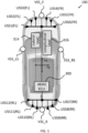
- FIG. 1 illustrates an example of a vehicle 100 in which embodiments of the invention can be implemented.
- the vehicle 100 is a passenger vehicle, also referred to as a passenger car or as an automobile.
- embodiments of the invention can be implemented for other applications, such as commercial vehicles.
- FIG. 1 is a top-down view and illustrates a longitudinal x-axis between the front and rear of the vehicle 100, and an orthogonal lateral y-axis between left and right lateral sides of the vehicle 100. Rotation about the y-axis is pitch and rotation about the x-axis is roll.
- a forward direction typically faced by a driver's seat is in the positive x-direction; rearward is -x. These are a first longitudinal direction and a second longitudinal direction.
- a rightward direction as seen from the driver's seat is in the positive y-direction; leftward is -y. These are a first lateral direction and a second lateral direction.
- the vehicle 100 of FIG. 1 is equipped with a driver assistance system (e.g. ADAS).
- ADAS operates in dependence on information from a plurality of sensors.
- An example sensor layout is shown in FIGS. 1 and 2A-2C . It would be appreciated that the sensors and/or layout could be different from those shown.
- FIG. 1 illustrates the sensor layout.
- FIG. 2A illustrates the corresponding sensing region of each sensor on a horizontal plane, the shape schematically indicating a functional range of the sensor. The illustrated shape is approximately semicircular but could be tunable depending on the sensor specification and mounting position.
- FIGS. 2B and 2C show a sensor axis (centre of field of view) offset from the x-axis by a horizontal angle ⁇ and by a vertical angle ⁇ .
- the sensors comprise first sensors (e.g. USS1, USS2...) providing a first sensor modality and second sensors (e.g. VSS_F, VSS_R%) providing a second sensor modality.
- first sensors e.g. USS1, USS2
- second sensors e.g. VSS_F, VSS_R
- the sensors provide only one sensor modality or provide more than two sensor modalities.
- the first sensor modality is an ultrasonic sensor modality and the second sensor modality is a vision sensor modality. In other examples at least one of the sensor modalities is different.
- An ultrasonic sensor modality is enabled by a plurality of ultrasonic sensors at different locations on the vehicle body, wherein the ultrasonic sensors are configured to act at least as parking sensors. Therefore in at least some examples a plurality of ultrasonic sensors is provided at least on a rear bumper of the vehicle 100. Optionally, and as shown, a plurality of ultrasonic sensors is also provided on a front bumper of the vehicle 100.
- the ultrasonic sensors comprise sets of a plurality (e.g. three) ultrasonic sensors for each vehicle corner (quarter).
- the sensors may approximately follow bumper curvature, meaning that ⁇ generally diverges from the x-axis with a greater y-axis positional offset from the centre x-axis.
- the ultrasonic sensors comprise at least some of:
- a vision sensor modality is configured to detect electromagnetic radiation. Examples include visual light spectrum cameras, light detection and ranging (LIDAR), radio detection and ranging (RADAR), or near-infrared.
- LIDAR light detection and ranging
- RADAR radio detection and ranging
- the vision sensor modality is enabled by visual light spectrum cameras ( ⁇ vision sensors' herein) configured to provide data to image processors implementing computer vision algorithms.
- a vision sensor modality is enabled by a plurality of vision sensors each having a horizontal field of view less than 360° and located at different positions on the vehicle body facing in different directions.
- a single 360° vision sensor may be provided.
- the vision sensors comprise at least some of:
- the vison sensors may have longer sensing ranges than the ultrasonic sensors as shown in FIG. 2 by their larger sensing regions extending further away from the vehicle 100 than the sensing regions of the ultrasonic sensors.
- the ADAS utilises a sensor fusion algorithm to combine information from each of the sensor modalities (e.g. VSS+USS) in order to improve obstacle, feature and/or pedestrian detection and classification, to enhance system performance, and/or to build redundancy.
- the sensor fusion algorithm may utilise vision sensors for finding road markings, road signs, parking spaces, and obstacles (e.g. pedestrians, vehicles and roadside furniture).
- Ultrasonic data may be overlaid onto the vision data as a lower layer, to improve confidence. Ultrasonic sensors can detect 3D obstacles that reflect ultrasonic radiation.
- the ADAS is configured to use information from first sensors to control automated manoeuvring of the vehicle 100 in a first longitudinal direction (e.g. +x) and/or to control detection of objects (e.g. parking spaces and/or obstacles) offset from the vehicle 100 in the first longitudinal direction.
- the first sensors have sensor axes extending at least partially in the first longitudinal direction.
- the first sensors comprise at least some of USS1, USS2, USS3, USS4, USS5, USS6, VSS_F, VSS_LS, VSS_RS.
- the ADAS is configured to use information from second sensors to control automated manoeuvring of the vehicle 100 in a second longitudinal direction (e.g. -x) and/or to control detection of objects (e.g. parking spaces and/or obstacles) offset from the vehicle 100 in the second longitudinal direction.
- the second sensors have sensor axes extending at least partially in the first longitudinal direction.
- the second sensors comprise at least some of USS7, USS8, USS9, USS10, USS11, USS12, VSS_R, VSS_LS, VSS_RS.
- the ADAS is configured to use information from subsets of the first and/or second sensors to control automated steering of the vehicle 100 in first and/or second lateral directions during a longitudinal manoeuvre, and/or is configured to use the information to control detection of objects (e.g. parking spaces and/or obstacles) offset from the vehicle 100 in the first and/or second lateral directions.
- the subsets of sensors may depend on whether the vehicle 100 is moving forward (+x) or in reverse (-x). At least some of the following sensors are used for the following manoeuvres/parking space detection searching directions:
- FIG. 1 illustrates a control system 300 operably coupled to a lateral vehicle motion controller (VMC) 314 and a longitudinal VMC 316.
- the lateral VMC 314 controls an electronic power steering actuator.
- the longitudinal VMC 316 controls a torque source and a braking system..
- the lateral and longitudinal VMCs are functions of a single VMC.
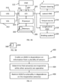
- FIG. 3 illustrates a system 1 comprising the control system 300 and one or more other optional components.
- the control system 300 comprises at least one controller 301.
- the controller 301 of FIG. 3 includes at least one processor 304; and at least one memory device 306 electrically coupled to the electronic processor 304 and having instructions 308 (e.g. a computer program) stored therein, the at least one memory device 306 and the instructions 308 configured to, with the at least one processor 304, cause any one or more of the methods described herein to be performed.
- the processor 304 may have an interface 302 such as an electrical input/output I/O or electrical input for receiving information and interacting with external components.
- the control system 300 of FIG. 3 is configured to receive information from ultrasonic sensors (USS) 310 and from vision sensors (VSS) 312. If the control system 300 can perform automated longitudinal control (acceleration and/or braking), the control system 300 may be operably coupled to a torque source 316 and/or a braking system 320, optionally via a longitudinal VMC 318.
- the torque source 316 may comprise an internal combustion engine and/or an electric machine, for example.
- the braking system 320 may comprise a friction braking system and/or a regenerative braking system, for example.
- the control system 300 can perform automated lateral control (steering)
- EPS electronic power steering actuator
- the control system 300 of FIG. 3 may be configured to transmit information to an HMI 322 comprising an output device, for rendering information to a user.
- the control system 300 may be configured to receive user inputs from the same or a different HMI 322 comprising an input device.
- the HMI 322 may comprise an input/output device such as a touchscreen display, for example.
- the HMI 322 available to the control system 300 may comprise multiple devices such as audio rendering devices and display devices.
- FIG. 3B illustrates a non-transitory computer-readable storage medium 330 comprising the instructions 308 (computer software).
- the ADAS is configured to provide one or more parking assistance functions.
- Parking assistance functions may be categorised as automated parking or parking space detection.
- An example automated parking function is perpendicular parking.
- Perpendicular parking means parking cars side-by-side.
- the perpendicular parking function may either drive forwards (nose first) or reverse (rear first) into a detected perpendicular parking space. In tight spaces the perpendicular parking function may shuffle the vehicle 100 forwards and/or backwards one or more times to complete a multi-point turn to orient the vehicle 100 into the perpendicular parking space.
- the perpendicular parking function also performs automated steering (full automatic park feature). In another embodiment steering remains the responsibility of the driver.
- Parallel parking means parking cars end-to-end.
- the parallel parking function may reverse (rear first) into a detected parallel parking space.
- the parallel parking function may shuffle the vehicle 100 forwards while steering towards the space, after having reversed in. This brings the nose of the vehicle 100 into the space to finalise the parallel orientation. For very tight spaces additional forwards/reverse shuffling is required. Steering may either be automated or manual as described above.
- Remote parking assistance enables the driver to exit the vehicle 100 prior to commencement of the manoeuvre, which is convenient for parking in narrow garages or bays with limited space for opening a door.
- the ADAS is in communication with a portable electronic device of the driver (e.g. mobile phone, smart watch, virtual reality glasses, etc.).
- the driver uses a HMI 322 on their device to send parking instructions such as forward exploration, rearward exploration, forward nudging and/or rearward nudging.
- Nudging comprises the driver using the remote HMI 322 (e.g. slide and hold interaction) to manually trigger the control system 300 to cause one incremental longitudinal movement in response, during which the control system 300 also controls steering automatically based on the sensors.
- the control system 300 may also use the sensors to prevent collision with sensed obstacles if following the driver trigger would cause a collision.
- the incremental longitudinal movement could be in the order of 1-10 centimetres, or at most less than 40 centimetres.
- An exploration is a parking manoeuvre, in which the system 1 has not scanned/determined the parking space well in advance so the environment is unfamiliar. In this case the system 1 will sense the environment on the fly (while vehicle in motion).
- Example use cases include parking the vehicle inside a garage or driving out from the garage
- An example parking space detection function is line-to-line parking space detection.
- Lines comprise painted lines.
- a detected pair of approximately parallel lines may be recognised as a line-to-line parking space.
- Line-to-line parking space detection may utilise a vision sensor.
- Another example parking space detection function is obstacle-to-obstacle parking space detection.
- the term 'vehicleto-vehicle' is used synonymously but a space could be bounded by objects other than vehicles, such as walls.
- a detected gap between parked vehicles/objects may be recognised as an obstacle-to-obstacle parking space.
- Either a vision sensor or an ultrasonic sensor (or both) are suitable.
- the parking manoeuvre into a detected space may be performed automatically.
- the parking space detection function may instead render an alert via an HMI 322 when a space meets parking suitability conditions (space size etc). The driver is alerted to perform the manoeuvre themselves.
- the parking space detection function may audibly/visually guide the driver regarding suggested steering/longitudinal inputs.
- successful automated parking may comprise multiple stages comprising multiple ones of the following manoeuvres: forward left; forward right; rearward left; rearward right. Therefore, different sensors are 'critical' at different times during the parking manoeuvre.
- the ADAS can in some instances remain enabled in a degraded (restricted) state depending on the inoperative one or more sensors. Further, if more sensors become inoperative the degradation may be staged with some features remaining available. This non binary degradation strategy is convenient for the driver especially if parts of their vehicle 100 are muddy.
- a method as shown in FIG. 4 comprising: at operation 402, enabling a driver assistance system (e.g. parking assist function) in dependence on information from a plurality of sensors; at operation 404, determining that one or more of the plurality of sensors is inoperative while another one or more of the plurality of sensors is operative; and at operation 406, restricting functionality of the enabled driver assistance system in dependence on the inoperative one or more sensors.
- operation 406 comprises restricting automated manoeuvring to a subset of one or more directions in dependence on the inoperative one or more of the sensors.
- operation 406 comprises restricting detection of parking spaces to a subset of one or more directions in dependence on the inoperative one or more of the sensors.
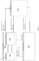
- FIG. 5 provides an example state machine for controlling ADAS degradation.
- the control system 300 may monitor the state continuously while the ADAS is enabled.
- the ADAS may be always-on or selectable via an HMI 322.
- the parking assistance functions may include at least some of: a perpendicular parking function; a parallel parking function; a remote parking assistance function; a parking space detection function.
- a driver When a parking assistance function is enabled, a driver is able to trigger the parking assistance function via an HMI 322.
- a partially degraded (restricted) substate 504 ('Fusion_Sensor_Pairs_Ok') of the full system superstate 500 one or more non-critical sensors are inoperative while other critical sensors remain operative.
- a critical sensor may be a sensor whose failure cannot be tolerated in dependence on its known sensing region and sensor axis direction, and the associated implication on blind spots.
- a critical sensor may be a sensor whose failure means that the state machine cannot remain in the full system superstate 500.
- At least some of the above parking assistance functions may be restricted in some way while remaining enabled and selectable by the driver.
- operations e.g. automated manoeuvring, parking space detection
- operations in the direction of the failed non-critical sensor may be restricted without restricting operations in other directions.
- a manoeuvre in one direction could be automatic, but then the control system 300 could transmit a handover prompt to HMI 322 for output to a driver, prompting the driver to at least partially control manoeuvring in the direction of the failed critical sensor (e.g. take over steering, or take over steering and longitudinal control).
- a non-critical sensor failure transition condition ( ⁇ NonCriticalSens_Fail') changes substates from 502 to 504.
- Monitoring the non-critical sensor failure transition condition may comprise determining whether each of a plurality of automated manoeuvring directions comprises a minimum viable sensor set of operative sensors.
- the plurality of directions are decomposed to: forward left; forward right; reverse left; and reverse right.
- the plurality of directions are only forward or rear, or only left or right, or are decomposed to more than the four given directions.
- Determining whether a sensor is operative may comprise determining whether a diagnostic trouble code (DTC) in relation to that sensor is received or stored in memory, for example.
- DTC diagnostic trouble code
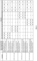
- FIG. 6 provides an example of which sensors must be operative ('OK') for automated parking operations in each given direction, and which sensors are irrelevant and allowed to fail for each given direction (designated by 'X' and 'NOK').
- the state machine is in the fully operational substate 502.
- FIG. 6 requires that the minimum viable sensor set for each direction is all ultrasonic sensors (e.g. all three). In an alternative embodiment the minimum viable sensor set could be fewer than all ultrasonic sensors.
- a reverse ultrasonic sensor e.g. USS7
- a reverse manoeuvre is inhibited but other manoeuvres are not inhibited.
- Inhibiting means causing driver handover as described above.
- the inhibited manoeuvre could be lateral direction-specific. For example, loss of USS7 inhibits a reverse right manoeuvre but not a reverse left manoeuvre.
- the non-critical sensor failure transition condition is satisfied and manoeuvring in that direction is inhibited.
- the continuing loss of ultrasonic sensors remains non-critical until all manoeuvring directions are inhibited, at which point the sensor loss is critical because manoeuvring is no longer possible in any direction.
- the number of available automatic manoeuvring directions degrades progressively as additional sensors become inoperative, until the number of automatic manoeuvring directions drops below a minimum (e.g. drops to zero).
- the loss of vision sensors does not prohibit manoeuvring in any direction and therefore does not change states in the state machine, as long as enough ultrasonic sensors remain operative. Instead, the loss of vision sensors may cause a transition between different modes of the automated parking function.
- the modes comprise:
- the state machine further comprises a parking space detection-only state 510 ( ⁇ Only_ParkSpace_Detection') in which automated parking functions are fully inhibited (e.g. not enabled) and therefore not possible to trigger via HMI 322.
- the parking space detection function may remain enabled and therefore possible to trigger via HMI 322.
- the parking space detection transition condition may have two requirements:
- the state machine instead transitions from state 500 to a no park assist state 520 ('No_System_Available') in which no parking assistance functions are available.
- FIG. 7 provides a non-limiting example of which sensors should be operative for parking space detection.
- FIG. 7 is a table that is similarly laid out to FIG. 6 , except relating to parking space detection rather than automated manoeuvring.
- the minimum viable sensor sets for parking space detection are more tolerant than the minimum viable sensor sets for automated manoeuvring.
- the minimum viable sensor sets for parking space detection are specific to each of a plurality of different directions, optionally the same directions as those shown in FIG. 6 .
- the minimum viable sensor set for parking space detection in a given direction is:
- the minimum viable sensor set for parking space detection of one sensor modality depends on the number of operative sensors of that sensor modality and also depends on the number of operative sensors in the other sensor modality.
- the number of available parking space detection directions degrade progressively as additional sensors become inoperative, until the number of available parking space detection directions drops below a minimum (e.g. drops to zero).
- the control system 300 may transmit information to an HMI 322 for providing to the driver an indication of which parking space detection directions are available and/or unavailable.
- a no park assist transition condition is satisfied ( ⁇ AIISensPair_Fail'), causing a transition to the no park assist state 520 in which no parking assistance functions are available.
- the loss of vision sensors may cause a transition between different modes of the parking space detection function.
- the modes may progressively degrade line-to-line parking space detection while maintaining obstacle-to-obstacle parking space detection.
- the modes comprise:
- the above-mentioned sensor failure transition conditions of the state machine of FIG. 5 may be accompanied by sensor recovery transition conditions to recover from state 520 to 500 or 510, and from state 510 to 500.
- a sensor recovery transition occurs when there are enough recovered sensors to ensure that all required minimum viable sensor sets of the state 500 or 510 are now operable.
- FIG. 8 is a flowchart 800 equivalent to the state machine.
- controller(s) described herein can each comprise a control unit or computational device having one or more electronic processors.
- a vehicle 100 and/or a system thereof may comprise a single control unit or electronic controller or alternatively different functions of the controller(s) may be embodied in, or hosted in, different control units or controllers.
- a set of instructions could be provided which, when executed, cause said controller(s) or control unit(s) to implement the control techniques described herein (including the described method(s)).
- the set of instructions may be embedded in one or more electronic processors, or alternatively, the set of instructions could be provided as software to be executed by one or more electronic processor(s).
- a first controller may be implemented in software run on one or more electronic processors, and one or more other controllers may also be implemented in software run on one or more electronic processors, optionally the same one or more processors as the first controller. It will be appreciated, however, that other arrangements are also useful, and therefore, the present invention is not intended to be limited to any particular arrangement.
- the set of instructions described above may be embedded in a computer-readable storage medium (e.g., a non-transitory computer-readable storage medium) that may comprise any mechanism for storing information in a form readable by a machine or electronic processors/computational device, including, without limitation: a magnetic storage medium (e.g., floppy diskette); optical storage medium (e.g., CD-ROM); magneto optical storage medium; read only memory (ROM); random access memory (RAM); erasable programmable memory (e.g., EPROM and EEPROM); flash memory; or electrical or other types of medium for storing such information/instructions.
- a computer-readable storage medium e.g., a non-transitory computer-readable storage medium
- a magnetic storage medium e.g., floppy diskette
- optical storage medium e.g., CD-ROM
- magneto optical storage medium e.g., magneto optical storage medium
- ROM read only memory
- RAM random access memory
- FIGS. 4-5 may represent steps in a method and/or sections of code in the computer program 308.
- the illustration of a particular order to the blocks does not necessarily imply that there is a required or preferred order for the blocks and the order and arrangement of the block may be varied. Furthermore, it may be possible for some steps to be omitted.
Landscapes
- Engineering & Computer Science (AREA)
- Automation & Control Theory (AREA)
- Transportation (AREA)
- Mechanical Engineering (AREA)
- Human Computer Interaction (AREA)
- Chemical & Material Sciences (AREA)
- Combustion & Propulsion (AREA)
- Traffic Control Systems (AREA)
Description
- The present invention relates to driver assistance with inoperative sensors. In particular, but not exclusively it relates to parking assistance when one or more sensors are inoperative while another one or more sensors is operative.
- Automated driving systems (ADS), also referred to as Advanced driver-assistance systems (ADAS), are electronic systems that assist drivers in driving and parking functions and/or automate parts of driving tasks. ADAS systems use automated technology, such as sensors, to detect nearby obstacles or to detect hazards. ADAS systems are able to perform one or more of: longitudinal vehicle control (automated acceleration and/or automated braking); lateral vehicle control (automated steering); and process driver inputs and alert the driver to a hazard or opportunity via a humanmachine interface (HMI).
- Examples of ADAS include: autonomous emergency braking; driver condition monitoring; traffic sign recognition; adaptive cruise control; blind spot assist; reverse crossing traffic detection; and parking assistance, among others.
- An ADAS function may be disabled completely if one sensor of a plurality of sensors is inoperative, even if the other operative sensors may provide situational awareness regarding the majority of the environment surrounding the vehicle. A sensor may become inoperative if it is blocked by dirt or insects, or if a detectable fault occurs.
- For further information relating to a vehicle control system for a vehicle with a plurality of environment sensors which have different or overlapping detection areas, the reader is directed to German patent application number
DE-A1-10-2017-204603 US-A1-2020/406890 . - It is an aim of the present invention to address one or more of the disadvantages associated with the prior art.
- According to an aspect of the invention there is provided a control system for a vehicle, the control system comprising one or more controllers, wherein the control system is configured to: enable a driver assistance system in dependence on information from a plurality of sensors; determine that one or more of the plurality of sensors is inoperative while another one or more of the plurality of sensors is operative; and restrict functionality of the enabled driver assistance system in dependence on the inoperative one or more sensors, wherein the driver assistance system is configured to provide one or more parking assistance functions, the one or more parking assistance functions comprising automated parking and parking space detection, and wherein restricting the functionality comprises restricting automated parking without restricting parking space detection, in dependence on the inoperative one or more of the sensors, such that, when automated parking is not available, the parking space detection function is operable to render an alert via a human machine interface (HMI) when a detected parking space meets parking suitability conditions and to alert a driver that parking in said detected space has to be performed manually. An advantage is that the driver assistance system is more frequently usable, due to a staged degradation process.
- In some examples, restricting the functionality comprises restricting automated manoeuvring to a subset of one or more directions in dependence on the inoperative one or more of the sensors.
- In some examples, restricting the functionality comprises transmitting a prompt for output to a driver, prompting the driver to control manoeuvring when manoeuvring in another direction is required, not from the subset of one or more directions.
- In some examples, the control system is configured to restrict functionality of the driver assistance system in dependence on at least one of: in which longitudinal direction a sensing axis of the inoperative one or more of the sensors extends; in which lateral direction a sensing axis of the inoperative one or more of the sensors is positionally and/or angularly offset; and a sensor modality of the inoperative one or more of the sensors.
- In some examples, the plurality of sensors comprise sensors providing a first sensor modality and optionally sensors providing a second sensor modality, and wherein the vehicle is configured to be manoeuvred in a first longitudinal direction and in a second longitudinal direction and is configured to be steered in a first lateral direction and in a second lateral direction.
- In some examples, the first sensor modality is an ultrasonic sensor modality, and wherein the second sensor modality is a vision sensor modality.
- In some examples, when the inoperative one or more of the sensors includes at least one sensor providing the first sensor modality with a sensor axis extending in the first longitudinal direction, restricting the functionality comprises at least partially inhibiting automated manoeuvring in the first longitudinal direction without inhibiting automated manoeuvring in the second longitudinal direction.
- In some examples, if the sensor axis is angularly and/or positionally offset in the first lateral direction, at least partially inhibiting automated manoeuvring in the first longitudinal direction comprises inhibiting automated manoeuvring in the first longitudinal direction with steering in the first lateral direction without inhibiting automated manoeuvring in the first longitudinal direction with steering in the second lateral direction.
- In some examples, when the one or more inoperative sensors includes at least one sensor providing the second sensor modality but does not include at least one sensor providing the first sensor modality, automated manoeuvring in the first longitudinal direction is not inhibited.
- In some examples, when the inoperative one or more of the sensors includes a subset of at least one sensor providing the first sensor modality and having a sensor axis extending in the first longitudinal direction, restricting the functionality comprises at least partially inhibiting automated manoeuvring of the vehicle in the first longitudinal direction without inhibiting detection of parking spaces offset from the vehicle in the first longitudinal direction.
- In some examples, if the sensor axis is angularly and/or positionally offset in the first lateral direction, restricting the functionality comprises inhibiting automated manoeuvring of the vehicle in the first longitudinal direction with steering in the first lateral direction without inhibiting automated manoeuvring in the first longitudinal direction with steering in the second lateral direction and without inhibiting detection of parking spaces offset from the vehicle in the first longitudinal direction.
- In some examples, the driver assistance system is configured to fuse the information from the plurality of sensors, comprising fusing information from different sensor modalities.
- According to an aspect of the invention there is provided a vehicle comprising the control system as previously described.
- According to an aspect of the invention there is provided a method of controlling a driver assistance system, the driver assistance system being configured to provide one or more parking assistance functions, the one or more parking assistance functions comprising automated parking and parking space detection, the method comprising: enabling the driver assistance system in dependence on information from a plurality of sensors; determining that one or more of the plurality of sensors is inoperative while another one or more of the plurality of sensors is operative; restricting functionality of the enabled driver assistance system in dependence on the inoperative one or more sensors, wherein restricting the functionality comprises restricting automated parking without restricting parking space detection, in dependence on the inoperative one or more of the sensors; and, when automated parking is not available, rendering an alert via a human machine interface (HMI) when a detected parking space meets parking suitability conditions and alerting a driver that parking in said detected space has to be performed manually.
- According to an aspect of the invention there is provided computer software that, when executed, is arranged to perform the method. According to a further aspect of the invention there is provided a non-transitory computer readable medium comprising computer readable instructions that, when executed by a processor, cause performance of any one or more of the methods described herein.
- The one or more controllers may collectively comprise: at least one electronic processor having an electrical input for receiving information; and at least one electronic memory device electrically coupled to the at least one electronic processor and having instructions stored therein; and wherein the at least one electronic processor is configured to access the at least one memory device and execute the instructions thereon so as to cause the control system to cause performance of the method.
- One or more embodiments of the invention will now be described, by way of example only, with reference to the accompanying drawings, in which:
-
FIG. 1 illustrates an example of a vehicle with a plurality of sensors; -
FIGS. 2A, 2B, 2C illustrates an example of sensing regions and fields of view of the sensors of the vehicle; -
FIGS. 3A, 3B illustrate an example of a system and a non-transitory computer-readable storage medium; -
FIG. 4 illustrates an example of a method; -
FIG. 5 illustrates an example of a state machine; -
FIG. 6 illustrates an example degradation strategy table for an automated parking function; -
FIG. 7 illustrates an example degradation strategy table for a parking space detection function; and -
FIG. 8 illustrates an example method. -
FIG. 1 illustrates an example of avehicle 100 in which embodiments of the invention can be implemented. In some, but not necessarily all examples, thevehicle 100 is a passenger vehicle, also referred to as a passenger car or as an automobile. In other examples, embodiments of the invention can be implemented for other applications, such as commercial vehicles. -
FIG. 1 is a top-down view and illustrates a longitudinal x-axis between the front and rear of thevehicle 100, and an orthogonal lateral y-axis between left and right lateral sides of thevehicle 100. Rotation about the y-axis is pitch and rotation about the x-axis is roll. A forward direction typically faced by a driver's seat is in the positive x-direction; rearward is -x. These are a first longitudinal direction and a second longitudinal direction. A rightward direction as seen from the driver's seat is in the positive y-direction; leftward is -y. These are a first lateral direction and a second lateral direction. - The
vehicle 100 ofFIG. 1 is equipped with a driver assistance system (e.g. ADAS). The ADAS operates in dependence on information from a plurality of sensors. An example sensor layout is shown inFIGS. 1 and2A-2C . It would be appreciated that the sensors and/or layout could be different from those shown. -
FIG. 1 illustrates the sensor layout.FIG. 2A illustrates the corresponding sensing region of each sensor on a horizontal plane, the shape schematically indicating a functional range of the sensor. The illustrated shape is approximately semicircular but could be tunable depending on the sensor specification and mounting position.FIGS. 2B and 2C show a sensor axis (centre of field of view) offset from the x-axis by a horizontal angle α and by a vertical angle β. - The following definitions are used regarding angles:
- α=0° is regarded as extending in the +x-axis and α=180° is regarded as extending in the -x-axis;
- α=90° is regarded as extending in the +y-axis (rightwards) and α=270° is regarded as extending in the -y-axis (leftwards);
- β is outside the scope of the claimed invention but is assumed to be close to zero for the purposes of simplicity.
- In
FIG. 1 the sensors comprise first sensors (e.g. USS1, USS2...) providing a first sensor modality and second sensors (e.g. VSS_F, VSS_R...) providing a second sensor modality. In other examples the sensors provide only one sensor modality or provide more than two sensor modalities. - In
FIG. 1 the first sensor modality is an ultrasonic sensor modality and the second sensor modality is a vision sensor modality. In other examples at least one of the sensor modalities is different. - An ultrasonic sensor modality is enabled by a plurality of ultrasonic sensors at different locations on the vehicle body, wherein the ultrasonic sensors are configured to act at least as parking sensors. Therefore in at least some examples a plurality of ultrasonic sensors is provided at least on a rear bumper of the
vehicle 100. Optionally, and as shown, a plurality of ultrasonic sensors is also provided on a front bumper of thevehicle 100. - In
FIG. 1 the ultrasonic sensors comprise sets of a plurality (e.g. three) ultrasonic sensors for each vehicle corner (quarter). The sensors may approximately follow bumper curvature, meaning that α generally diverges from the x-axis with a greater y-axis positional offset from the centre x-axis. In an example the ultrasonic sensors comprise at least some of: - front left (FL) ultrasonic sensors USS1, USS2, USS3, wherein 240°<α(USS1)<300°, wherein α(USS1)<α(USS2)<α(USS3), and wherein 330°<α(USS3)<0°. The front-left USS therefore detect objects in a region to the front left of the
vehicle 100. - front right (FR) ultrasonic sensors USS4, USS5, USS6, wherein 0<α(USS4)<30°, wherein α(USS4)<α(USS5)<α(USS6), and wherein 60°<α(USS6)<120°. The front-right USS are therefore configured to (mainly) detect objects in a region to the front right of the
vehicle 100. - rear right (RR) ultrasonic sensors USS7, USS8, USS9, wherein 60°<α(USS7)<120°, wherein α(USS7)<α(USS8)<α(USS9), and wherein 150°<α(USS9)<180°. The rear-right USS are therefore configured to (mainly) detect objects in a region to the rear right of the
vehicle 100. - rear left (RL) ultrasonic sensors USS10, USS11, USS12, wherein 180°<α(USS10)<210°, wherein α(USS10)<α(USS11)<α(USS12), and wherein 240°<α(USS12)<300°. The rear-left USS are therefore configured to (mainly) detect objects in a region to the rear left of the
vehicle 100. - In some examples, a vision sensor modality is configured to detect electromagnetic radiation. Examples include visual light spectrum cameras, light detection and ranging (LIDAR), radio detection and ranging (RADAR), or near-infrared.
- In
FIG. 1 , but not necessarily all examples the vision sensor modality is enabled by visual light spectrum cameras (`vision sensors' herein) configured to provide data to image processors implementing computer vision algorithms. - A vision sensor modality is enabled by a plurality of vision sensors each having a horizontal field of view less than 360° and located at different positions on the vehicle body facing in different directions. Alternatively, a single 360° vision sensor may be provided. In an example the vision sensors comprise at least some of:
- a front vision sensor VSS_F facing α≈0° or 330°<α(VSS_F)<30°.
- a right side vision sensor VSS_RS facing α≈90° or 60°<α(VSS_RS)<120°.
- a rear vision sensor VSS_R facing α≈180° or 150°<α(VSS_R)<210°.
- a left side vision sensor VSS_LS facing α≈270° or wherein 240°<α(VSS_LS)<300°.
- The vison sensors may have longer sensing ranges than the ultrasonic sensors as shown in
FIG. 2 by their larger sensing regions extending further away from thevehicle 100 than the sensing regions of the ultrasonic sensors. - In some, but not necessarily all examples the ADAS utilises a sensor fusion algorithm to combine information from each of the sensor modalities (e.g. VSS+USS) in order to improve obstacle, feature and/or pedestrian detection and classification, to enhance system performance, and/or to build redundancy. The sensor fusion algorithm may utilise vision sensors for finding road markings, road signs, parking spaces, and obstacles (e.g. pedestrians, vehicles and roadside furniture). Ultrasonic data may be overlaid onto the vision data as a lower layer, to improve confidence. Ultrasonic sensors can detect 3D obstacles that reflect ultrasonic radiation.
- In at least some examples the ADAS is configured to use information from first sensors to control automated manoeuvring of the
vehicle 100 in a first longitudinal direction (e.g. +x) and/or to control detection of objects (e.g. parking spaces and/or obstacles) offset from thevehicle 100 in the first longitudinal direction. The first sensors have sensor axes extending at least partially in the first longitudinal direction. In an example the first sensors comprise at least some of USS1, USS2, USS3, USS4, USS5, USS6, VSS_F, VSS_LS, VSS_RS. - In at least some examples the ADAS is configured to use information from second sensors to control automated manoeuvring of the
vehicle 100 in a second longitudinal direction (e.g. -x) and/or to control detection of objects (e.g. parking spaces and/or obstacles) offset from thevehicle 100 in the second longitudinal direction. The second sensors have sensor axes extending at least partially in the first longitudinal direction. In an example the second sensors comprise at least some of USS7, USS8, USS9, USS10, USS11, USS12, VSS_R, VSS_LS, VSS_RS. - In at least some examples the ADAS is configured to use information from subsets of the first and/or second sensors to control automated steering of the
vehicle 100 in first and/or second lateral directions during a longitudinal manoeuvre, and/or is configured to use the information to control detection of objects (e.g. parking spaces and/or obstacles) offset from thevehicle 100 in the first and/or second lateral directions. The subsets of sensors may depend on whether thevehicle 100 is moving forward (+x) or in reverse (-x). At least some of the following sensors are used for the following manoeuvres/parking space detection searching directions: - Forward left = front left corner ultrasonic sensors (USS1, USS2, USS3), forward-facing vision sensor (VSS_F), left-facing vision sensor (VSS_LS).
- Forward right = front right corner ultrasonic sensors (USS4, USS5, USS6), forward-facing vision sensor (VSS_F), right-facing vision sensor (VSS_RS).
- Rear right = rear right corner ultrasonic sensors (USS7, USS8, USS9), rear-facing vision sensor (VSS_R), right-facing vision sensor (VSS_RS).
- Rear left = rear left corner ultrasonic sensors (USS10, USS11, USS12), rear-facing vision sensor (VSS_R), left-facing vision sensor (VSS_LS).
-
FIG. 1 illustrates acontrol system 300 operably coupled to a lateral vehicle motion controller (VMC) 314 and alongitudinal VMC 316. Thelateral VMC 314 controls an electronic power steering actuator. Thelongitudinal VMC 316 controls a torque source and a braking system.. In some implementations the lateral and longitudinal VMCs are functions of a single VMC. In more detail,FIG. 3 illustrates asystem 1 comprising thecontrol system 300 and one or more other optional components. - The
control system 300 comprises at least onecontroller 301. Thecontroller 301 ofFIG. 3 includes at least oneprocessor 304; and at least onememory device 306 electrically coupled to theelectronic processor 304 and having instructions 308 (e.g. a computer program) stored therein, the at least onememory device 306 and theinstructions 308 configured to, with the at least oneprocessor 304, cause any one or more of the methods described herein to be performed. Theprocessor 304 may have aninterface 302 such as an electrical input/output I/O or electrical input for receiving information and interacting with external components. - The
control system 300 ofFIG. 3 is configured to receive information from ultrasonic sensors (USS) 310 and from vision sensors (VSS) 312. If thecontrol system 300 can perform automated longitudinal control (acceleration and/or braking), thecontrol system 300 may be operably coupled to atorque source 316 and/or abraking system 320, optionally via alongitudinal VMC 318. Thetorque source 316 may comprise an internal combustion engine and/or an electric machine, for example. Thebraking system 320 may comprise a friction braking system and/or a regenerative braking system, for example. If thecontrol system 300 can perform automated lateral control (steering), thecontrol system 300 can be operably coupled to an electronic power steering actuator (EPS) 315, optionally via alateral VMC 314 - The
control system 300 ofFIG. 3 may be configured to transmit information to anHMI 322 comprising an output device, for rendering information to a user. Thecontrol system 300 may be configured to receive user inputs from the same or adifferent HMI 322 comprising an input device. TheHMI 322 may comprise an input/output device such as a touchscreen display, for example. TheHMI 322 available to thecontrol system 300 may comprise multiple devices such as audio rendering devices and display devices. -
FIG. 3B illustrates a non-transitory computer-readable storage medium 330 comprising the instructions 308 (computer software). - In at least some examples the ADAS is configured to provide one or more parking assistance functions. Parking assistance functions may be categorised as automated parking or parking space detection.
- An example automated parking function is perpendicular parking. Perpendicular parking means parking cars side-by-side. The perpendicular parking function may either drive forwards (nose first) or reverse (rear first) into a detected perpendicular parking space. In tight spaces the perpendicular parking function may shuffle the
vehicle 100 forwards and/or backwards one or more times to complete a multi-point turn to orient thevehicle 100 into the perpendicular parking space. In one embodiment the perpendicular parking function also performs automated steering (full automatic park feature). In another embodiment steering remains the responsibility of the driver. - Another example automated parking function is parallel parking. Parallel parking means parking cars end-to-end. The parallel parking function may reverse (rear first) into a detected parallel parking space. In tight spaces the parallel parking function may shuffle the
vehicle 100 forwards while steering towards the space, after having reversed in. This brings the nose of thevehicle 100 into the space to finalise the parallel orientation. For very tight spaces additional forwards/reverse shuffling is required. Steering may either be automated or manual as described above. - Another example automated parking function is remote parking assistance. Remote parking assistance enables the driver to exit the
vehicle 100 prior to commencement of the manoeuvre, which is convenient for parking in narrow garages or bays with limited space for opening a door. The ADAS is in communication with a portable electronic device of the driver (e.g. mobile phone, smart watch, virtual reality glasses, etc.). The driver uses aHMI 322 on their device to send parking instructions such as forward exploration, rearward exploration, forward nudging and/or rearward nudging. - Nudging comprises the driver using the remote HMI 322 (e.g. slide and hold interaction) to manually trigger the
control system 300 to cause one incremental longitudinal movement in response, during which thecontrol system 300 also controls steering automatically based on the sensors. Thecontrol system 300 may also use the sensors to prevent collision with sensed obstacles if following the driver trigger would cause a collision. The incremental longitudinal movement could be in the order of 1-10 centimetres, or at most less than 40 centimetres. - An exploration is a parking manoeuvre, in which the
system 1 has not scanned/determined the parking space well in advance so the environment is unfamiliar. In this case thesystem 1 will sense the environment on the fly (while vehicle in motion). Example use cases include parking the vehicle inside a garage or driving out from the garage - An example parking space detection function is line-to-line parking space detection. Lines comprise painted lines. A detected pair of approximately parallel lines may be recognised as a line-to-line parking space. Line-to-line parking space detection may utilise a vision sensor.
- Another example parking space detection function is obstacle-to-obstacle parking space detection. The term 'vehicleto-vehicle' is used synonymously but a space could be bounded by objects other than vehicles, such as walls. A detected gap between parked vehicles/objects may be recognised as an obstacle-to-obstacle parking space. Either a vision sensor or an ultrasonic sensor (or both) are suitable.
- If the ADAS is configured for parking space detection followed by automated parking, the parking manoeuvre into a detected space may be performed automatically.
- If an automated parking function is not available, the parking space detection function may instead render an alert via an
HMI 322 when a space meets parking suitability conditions (space size etc). The driver is alerted to perform the manoeuvre themselves. Optionally the parking space detection function may audibly/visually guide the driver regarding suggested steering/longitudinal inputs. - Based on the preceding paragraphs it will be understood that successful automated parking may comprise multiple stages comprising multiple ones of the following manoeuvres: forward left; forward right; rearward left; rearward right. Therefore, different sensors are 'critical' at different times during the parking manoeuvre.
- According to various aspects of the invention if a sensor becomes inoperative (e.g. blocked or faulty) while one or more other sensors remains operative, the ADAS can in some instances remain enabled in a degraded (restricted) state depending on the inoperative one or more sensors. Further, if more sensors become inoperative the degradation may be staged with some features remaining available. This non binary degradation strategy is convenient for the driver especially if parts of their
vehicle 100 are muddy. - Therefore, according to various aspects there is provided a method as shown in
FIG. 4 , the method comprising: atoperation 402, enabling a driver assistance system (e.g. parking assist function) in dependence on information from a plurality of sensors; atoperation 404, determining that one or more of the plurality of sensors is inoperative while another one or more of the plurality of sensors is operative; and atoperation 406, restricting functionality of the enabled driver assistance system in dependence on the inoperative one or more sensors. In some examples,operation 406 comprises restricting automated manoeuvring to a subset of one or more directions in dependence on the inoperative one or more of the sensors. In some examples,operation 406 comprises restricting detection of parking spaces to a subset of one or more directions in dependence on the inoperative one or more of the sensors. - Various examples of degradation (restriction) strategies are described below in relation to the Figures.
- Firstly
FIG. 5 provides an example state machine for controlling ADAS degradation. Thecontrol system 300 may monitor the state continuously while the ADAS is enabled. The ADAS may be always-on or selectable via anHMI 322. - In a full system superstate 500 ('Full_System_Available') enough sensors are operative that all parking assistance functions remain enabled in full or degraded (restricted) form. The parking assistance functions may include at least some of: a perpendicular parking function; a parallel parking function; a remote parking assistance function; a parking space detection function.
- When a parking assistance function is enabled, a driver is able to trigger the parking assistance function via an
HMI 322. - In a fully operational substate 502 ('All_Sensors_Ok') of the
full system superstate 500 all sensors are operative. All parking assistance functions are enabled including automated parking functions and parking space detection. - In a partially degraded (restricted) substate 504 ('Fusion_Sensor_Pairs_Ok') of the
full system superstate 500 one or more non-critical sensors are inoperative while other critical sensors remain operative. - A critical sensor may be a sensor whose failure cannot be tolerated in dependence on its known sensing region and sensor axis direction, and the associated implication on blind spots. A critical sensor may be a sensor whose failure means that the state machine cannot remain in the
full system superstate 500. - In the partially degraded substate, at least some of the above parking assistance functions may be restricted in some way while remaining enabled and selectable by the driver.
- In the partially degraded
substate 504, operations (e.g. automated manoeuvring, parking space detection) in the direction of the failed non-critical sensor may be restricted without restricting operations in other directions. For example, a manoeuvre in one direction could be automatic, but then thecontrol system 300 could transmit a handover prompt toHMI 322 for output to a driver, prompting the driver to at least partially control manoeuvring in the direction of the failed critical sensor (e.g. take over steering, or take over steering and longitudinal control). - A non-critical sensor failure transition condition (`NonCriticalSens_Fail') changes substates from 502 to 504. Monitoring the non-critical sensor failure transition condition may comprise determining whether each of a plurality of automated manoeuvring directions comprises a minimum viable sensor set of operative sensors.
- In the following examples, the plurality of directions are decomposed to: forward left; forward right; reverse left; and reverse right. In alternative examples, the plurality of directions are only forward or rear, or only left or right, or are decomposed to more than the four given directions.
- Determining whether a sensor is operative may comprise determining whether a diagnostic trouble code (DTC) in relation to that sensor is received or stored in memory, for example.
- Examples of non-critical sensor failures will be described in relation to
FIG. 6. FIG. 6 provides an example of which sensors must be operative ('OK') for automated parking operations in each given direction, and which sensors are irrelevant and allowed to fail for each given direction (designated by 'X' and 'NOK'). - As a starting point, if the minimum viable sensor set of each and every direction is satisfied, the state machine is in the fully
operational substate 502.FIG. 6 requires that the minimum viable sensor set for each direction is all ultrasonic sensors (e.g. all three). In an alternative embodiment the minimum viable sensor set could be fewer than all ultrasonic sensors. - If for example a reverse ultrasonic sensor (e.g. USS7) fails, a reverse manoeuvre is inhibited but other manoeuvres are not inhibited. Inhibiting means causing driver handover as described above. The inhibited manoeuvre could be lateral direction-specific. For example, loss of USS7 inhibits a reverse right manoeuvre but not a reverse left manoeuvre.
- Once the number of operative sensors drops below the minimum viable sensor set for any one of the directions, the non-critical sensor failure transition condition is satisfied and manoeuvring in that direction is inhibited. The continuing loss of ultrasonic sensors remains non-critical until all manoeuvring directions are inhibited, at which point the sensor loss is critical because manoeuvring is no longer possible in any direction. According to this example, the number of available automatic manoeuvring directions degrades progressively as additional sensors become inoperative, until the number of automatic manoeuvring directions drops below a minimum (e.g. drops to zero).
- In
FIG. 6 , but not necessarily all examples the loss of vision sensors does not prohibit manoeuvring in any direction and therefore does not change states in the state machine, as long as enough ultrasonic sensors remain operative. Instead, the loss of vision sensors may cause a transition between different modes of the automated parking function. InFIG. 6 , but not necessarily all examples the modes comprise: - Mode 1: Full functionality because a first set of vision sensors is operative. The first set could depend on the longitudinal direction of the manoeuvre. For example: forward = VSS_F+VSS_LS+VSS_RS; reverse =VSS_R+VSS_LS+VSS_RS.
- Mode 2: Degraded pedestrian/obstacle detection because operative vision sensors fall below a second set of vision sensors, a smaller subset of the first set. The second set could depend on the lateral direction of the manoeuvre. For example: For example: forward left = VSS_F+VSS_LS; forward right = VSS_F+VSS_RS; rear left=VSS_R+VSS_LS; rear right=VSS_R+VSS_RS. As a consequence of entering
mode 2, thecontrol system 300 may render an alert viaHMI 322, alerting the driver to a blind zone for vision-based pedestrian/object detection. In the illustrated example, manoeuvring in the direction of the inoperative vision sensor is not prohibited if a minimum number of ultrasonic sensors associated with the same direction remain operative. In another example, manoeuvring in the direction(s) associated with the inoperative vision sensor is prohibited without prohibiting manoeuvring in other directions. - Mode 3: Pedestrian detection inactive because operative vision sensors fall to zero or below a third set. As a consequence of entering
mode 3, thecontrol system 300 may render an alert viaHMI 322, alerting the driver to the lack of vision-based pedestrian/object detection. In the illustrated example, manoeuvring in the direction of the inoperative vision sensors is not prohibited if a minimum number of ultrasonic sensors associated with the same direction remain operative. In another example, manoeuvring in the directions associated with the inoperative vision sensors is prohibited. - The state machine further comprises a parking space detection-only state 510 (`Only_ParkSpace_Detection') in which automated parking functions are fully inhibited (e.g. not enabled) and therefore not possible to trigger via
HMI 322. However, the parking space detection function may remain enabled and therefore possible to trigger viaHMI 322. - A parking space detection transition condition ('Fusion_NotPossible AND OnlySpaceDetection=Enabled') changes state from 500 to 510.
- The parking space detection transition condition may have two requirements:
- 1 - critical sensor loss as defined above, so that automated parking functions are not available; and
- 2 - enough sensors remain operative that parking space detection can remain enabled.
- If the first but not the second requirement is satisfied, the state machine instead transitions from
state 500 to a no park assist state 520 ('No_System_Available') in which no parking assistance functions are available. - Regarding the second requirement, it would be useful to refer to
FIG. 7 which provides a non-limiting example of which sensors should be operative for parking space detection. -
FIG. 7 is a table that is similarly laid out toFIG. 6 , except relating to parking space detection rather than automated manoeuvring. The minimum viable sensor sets for parking space detection are more tolerant than the minimum viable sensor sets for automated manoeuvring. - In
FIG. 7 , but not necessarily all examples the minimum viable sensor sets for parking space detection are specific to each of a plurality of different directions, optionally the same directions as those shown inFIG. 6 . - In
FIG. 7 , the minimum viable sensor set for parking space detection in a given direction is: - a set (e.g. all three) of operative first sensors of a first sensor modality (e.g. ultrasonic sensors) for the given direction, if fewer than a minimum number (e.g. none) of the second sensors of a second sensor modality (e.g. VSS) for the given direction are operative; and/or
- a smaller subset (e.g. two) of the first sensors (e.g. ultrasonic sensors) for the given direction can be accepted, if at least the minimum number (e.g. one) of second sensors (e.g. VSS) for the given direction are operative (sensor fusion possible).
- In other words, the minimum viable sensor set for parking space detection of one sensor modality depends on the number of operative sensors of that sensor modality and also depends on the number of operative sensors in the other sensor modality.
- In
FIG. 7 , the number of available parking space detection directions degrade progressively as additional sensors become inoperative, until the number of available parking space detection directions drops below a minimum (e.g. drops to zero). - The
control system 300 may transmit information to anHMI 322 for providing to the driver an indication of which parking space detection directions are available and/or unavailable. - Once the number of available automatic manoeuvring directions drops below the minimum (e.g. zero), a no park assist transition condition is satisfied (`AIISensPair_Fail'), causing a transition to the no park assist
state 520 in which no parking assistance functions are available. - In
FIG. 7 , but not necessarily all examples the loss of vision sensors may cause a transition between different modes of the parking space detection function. The modes may progressively degrade line-to-line parking space detection while maintaining obstacle-to-obstacle parking space detection. InFIG. 7 , but not necessarily all examples the modes comprise: - Mode 1: Obstacle-to-obstacle parking space detection and line-to-line parking space detection are both enabled, because a first set of vision sensors is operative. The first set could depend on the longitudinal and/or lateral direction of the parking space detection. For example: forward left = VSS_F+VSS_LS; forward right = VSS_F+VSS_RS; rear left=VSS_R+VSS_LS; rear right=VSS_R+VSS_RS. In Mode 1 a smaller subset of ultrasonic sensors for the given direction can be accepted, such as two out of three ultrasonic sensors. Therefore, this mode of parking space detection can be available even if automated parking is not available, because automated parking requires the full set of ultrasonic sensors to be operative.
- Mode 2: Obstacle-to-obstacle parking space detection and limited line-to-line parking space detection are enabled, because operative vision sensors fall below a second set of vision sensors, a smaller subset of the first set. The second set could depend on the longitudinal direction of the parking space detection. For example: forward = VSS_F; rear=VSS_R. In
Mode 2 the smaller subset of ultrasonic sensors for the given direction can be accepted, compared to the number of operative ultrasonic sensors required for automated parking. Therefore, this mode of parking space detection can be available even if automated parking is not available. - Mode 3: Obstacle-to-obstacle parking space detection and limited line-to-line parking space detection are enabled, because operative vision sensors fall below a third set of vision sensors, a smaller subset of the first set and different from the second set. The third set could depend on the lateral direction of the parking space detection. For example: left = VSS_LS; right=VSS_RS. In
Mode 3 the smaller subset of ultrasonic sensors for the given direction can be accepted, compared to the number of operative ultrasonic sensors required for automated parking. Therefore, this mode of parking space detection can be available even if automated parking is not available. - Mode 4: Obstacle-to-obstacle parking space detection is enabled but line-to-line parking space detection is not enabled, because operative vision sensors fall to zero or below a fourth set. In Mode 4 the smaller subset of ultrasonic sensors for the given direction cannot be accepted. The full set of ultrasonic sensors for the given direction should be operative. This mode can coexist with
Mode 3 of automated parking (FIG. 6 ). - The above-mentioned sensor failure transition conditions of the state machine of
FIG. 5 may be accompanied by sensor recovery transition conditions to recover fromstate 520 to 500 or 510, and fromstate 510 to 500. A sensor recovery transition occurs when there are enough recovered sensors to ensure that all required minimum viable sensor sets of thestate -
FIG. 8 is aflowchart 800 equivalent to the state machine. -
Operation 802 is a start block. -
Operation 804 is an optional initialization block. -
Operation 806 comprises determining fitment and fields of view of the sensors for the ADAS parking assistance function. This may be factory-determined. -
Decision block 808 comprises determining whether all sensors are operative. Examples are provided earlier. - If all sensors are operative, the flowchart progresses to
operation 816 in which the ADAS is working at full capacity (e.g. state 500), then the process ends atoperation 824. - If not all sensors are operative, the flowchart progresses to
operation 810 which determines the criticality of the inoperative sensor(s).FIGS. 6 and7 provide example lookup tables for determining criticality. - After
operation 810,decision block 812 determines whether operation is allowed via sensor pairings (sensor fusion of remaining operative sensors), with reference to whether the inoperative sensors are critical.FIGS. 6 and7 provide example lookup tables for determining acceptable sensor pairings. - If sensor pairings is allowed,
operation 814 uses the alternative sensors to cover the missing field of view via sensor fusion. This operation links tooperation 816 in which the ADAS is working at full capacity, allowing automated parking. - If sensor pairings is not allowed, automated parking will be prohibited. Then,
operation 818 determines whether parking space searching can be performed with high confidence.FIG. 7 provides an example lookup table for thisoperation 818. - If parking space searching can be performed with high confidence,
operation 820 informs the user via anHMI 322 that valid spaces will be reported but parking has to be manual. This corresponds tostate 510. The process then ends atoperation 824. - If parking space searching cannot be performed with high confidence,
operation 822 disables the ADAS and informs the user. This corresponds tostate 520. The process then ends atoperation 824. - For purposes of this invention, it is to be understood that the controller(s) described herein can each comprise a control unit or computational device having one or more electronic processors. A
vehicle 100 and/or a system thereof may comprise a single control unit or electronic controller or alternatively different functions of the controller(s) may be embodied in, or hosted in, different control units or controllers. A set of instructions could be provided which, when executed, cause said controller(s) or control unit(s) to implement the control techniques described herein (including the described method(s)). The set of instructions may be embedded in one or more electronic processors, or alternatively, the set of instructions could be provided as software to be executed by one or more electronic processor(s). For example, a first controller may be implemented in software run on one or more electronic processors, and one or more other controllers may also be implemented in software run on one or more electronic processors, optionally the same one or more processors as the first controller. It will be appreciated, however, that other arrangements are also useful, and therefore, the present invention is not intended to be limited to any particular arrangement. In any event, the set of instructions described above may be embedded in a computer-readable storage medium (e.g., a non-transitory computer-readable storage medium) that may comprise any mechanism for storing information in a form readable by a machine or electronic processors/computational device, including, without limitation: a magnetic storage medium (e.g., floppy diskette); optical storage medium (e.g., CD-ROM); magneto optical storage medium; read only memory (ROM); random access memory (RAM); erasable programmable memory (e.g., EPROM and EEPROM); flash memory; or electrical or other types of medium for storing such information/instructions. - It will be appreciated that various changes and modifications can be made to the present invention without departing from the scope of the present invention as defined by the claims.
- The blocks illustrated in
FIGS. 4-5 may represent steps in a method and/or sections of code in thecomputer program 308. The illustration of a particular order to the blocks does not necessarily imply that there is a required or preferred order for the blocks and the order and arrangement of the block may be varied. Furthermore, it may be possible for some steps to be omitted. - Although embodiments of the present invention have been described in the preceding paragraphs with reference to various examples, it should be appreciated that modifications to the examples given can be made without departing from the scope of the invention as claimed. Some strategies described herein could be relevant to ADAS functions other than park assist functions, particularly low-speed functions. Further, the above examples refer primarily to the combination of ultrasonic sensors and vision sensors. In other embodiments, the different sensing modalities could comprise any different ones of: ultrasonic sensors; radar sensors; lidar sensors; or visual light spectrum cameras. Features described in the preceding description may be used in combinations other than the combinations explicitly described.
- Although functions have been described with reference to certain features, those functions may be performable by other features whether described or not. Although features have been described with reference to certain embodiments, those features may also be present in other embodiments whether described or not.
Claims (15)
- A control system (300) for a vehicle, the control system comprising one or more controllers (301), wherein the control system is configured to:enable (402) a driver assistance system in dependence on information from a plurality of sensors (310, 312);determine (404) that one or more of the plurality of sensors is inoperative while another one or more of the plurality of sensors is operative; andrestrict (406) functionality of the enabled driver assistance system in dependence on the inoperative one or more sensors,wherein the driver assistance system is configured to provide one or more parking assistance functions, the one or more parking assistance functions comprising automated parking and parking space detection, and wherein restricting the functionality comprises restricting automated parking without restricting parking space detection, in dependence on the inoperative one or more of the sensors, such that, when automated parking is not available, the parking space detection function is operable to render an alert (820) via a human machine interface (HMI) (322) when a detected parking space meets parking suitability conditions and to alert a driver that parking in said detected space has to be performed manually.
- The control system of claim 1, wherein restricting the functionality comprises restricting automated manoeuvring to a subset of one or more directions in dependence on the inoperative one or more of the sensors.
- The control system of claim 2, wherein restricting the functionality comprises transmitting a prompt for output to a driver, prompting the driver to control manoeuvring when manoeuvring in another direction is required, not from the subset of one or more directions.
- The control system of any preceding claim, wherein the control system is configured to restrict functionality of the driver assistance system in dependence on at least one of:in which longitudinal direction a sensing axis of the inoperative one or more of the sensors extends;in which lateral direction a sensing axis of the inoperative one or more of the sensors is positionally and/or angularly offset; anda sensor modality of the inoperative one or more of the sensors.
- The control system of any preceding claim, wherein the plurality of sensors comprise sensors providing a first sensor modality and sensors providing a second sensor modality, and wherein the vehicle is configured to be manoeuvred in a first longitudinal direction and in a second longitudinal direction and is configured to be steered in a first lateral direction and in a second lateral direction.;
- The control system of claim 5, wherein the first sensor modality is an ultrasonic sensor modality, and wherein the second sensor modality is a vision sensor modality.
- The control system of claim 5 or claim 6, wherein when the inoperative one or more of the sensors includes at least one sensor providing the first sensor modality with a sensor axis extending in the first longitudinal direction, restricting the functionality comprises at least partially inhibiting automated manoeuvring in the first longitudinal direction without inhibiting automated manoeuvring in the second longitudinal direction.
- The control system of claim 7, wherein, if the sensor axis is angularly and/or positionally offset in the first lateral direction, at least partially inhibiting automated manoeuvring in the first longitudinal direction comprises inhibiting automated manoeuvring in the first longitudinal direction with steering in the first lateral direction without inhibiting automated manoeuvring in the first longitudinal direction with steering in the second lateral direction.
- The control system of any one of claims 5 to 8, wherein, when the one or more inoperative sensors includes at least one sensor providing the second sensor modality but does not include at least one sensor providing the first sensor modality, automated manoeuvring in the first longitudinal direction is not inhibited.
- The control system of any one of claims 5 to 9, wherein when the inoperative one or more of the sensors includes a subset of at least one sensor providing the first sensor modality and having a sensor axis extending in the first longitudinal direction, restricting the functionality comprises at least partially inhibiting automated manoeuvring of the vehicle in the first longitudinal direction without inhibiting detection of parking spaces offset from the vehicle in the first longitudinal direction.
- The control system of claim 10, wherein if the sensor axis is angularly and/or positionally offset in the first lateral direction, restricting the functionality comprises inhibiting automated manoeuvring of the vehicle in the first longitudinal direction with steering in the first lateral direction without inhibiting automated manoeuvring in the first longitudinal direction with steering in the second lateral direction and without inhibiting detection of parking spaces offset from the vehicle in the first longitudinal direction;
- The control system of any preceding claim, wherein the driver assistance system is configured to fuse the information from the plurality of sensors, comprising fusing information from different sensor modalities.
- A vehicle (100) comprising the control system of any preceding claim.
- A method of controlling a driver assistance system, the driver assistance system being configured to provide one or more parking assistance functions, the one or more parking assistance functions comprising automated parking and parking space detection, the method comprising:enabling (402) the driver assistance system in dependence on information from a plurality of sensors;determining (404) that one or more of the plurality of sensors is inoperative while another one or more of the plurality of sensors is operative;restricting (406) functionality of the enabled driver assistance system in dependence on the inoperative one or more sensors, wherein restricting the functionality comprises restricting automated parking without restricting parking space detection, in dependence on the inoperative one or more of the sensors; andwhen automated parking is not available, rendering an alert (820) via a human machine interface (HMI) when a detected parking space meets parking suitability conditions and alerting a driver that parking in said detected space has to be performed manually.
- Computer software that, when executed, is arranged to perform a method according to claim 14.
Applications Claiming Priority (2)
| Application Number | Priority Date | Filing Date | Title |
|---|---|---|---|
| GB2017915.6A GB2600973B (en) | 2020-11-13 | 2020-11-13 | Driver assistance with inoperative sensors |
| PCT/EP2021/081588 WO2022101446A1 (en) | 2020-11-13 | 2021-11-12 | Driver assistance with inoperative sensors |
Publications (2)
| Publication Number | Publication Date |
|---|---|
| EP4244109A1 EP4244109A1 (en) | 2023-09-20 |
| EP4244109B1 true EP4244109B1 (en) | 2024-09-04 |
Family
ID=74046549
Family Applications (1)
| Application Number | Title | Priority Date | Filing Date |
|---|---|---|---|
| EP21815404.5A Active EP4244109B1 (en) | 2020-11-13 | 2021-11-12 | Driver assistance with inoperative sensors |
Country Status (3)
| Country | Link |
|---|---|
| EP (1) | EP4244109B1 (en) |
| GB (1) | GB2600973B (en) |
| WO (1) | WO2022101446A1 (en) |
Families Citing this family (2)
| Publication number | Priority date | Publication date | Assignee | Title |
|---|---|---|---|---|
| DE102021113810A1 (en) * | 2021-05-28 | 2022-12-01 | Ford Global Technologies, Llc | Method for operating a motor vehicle with a remote-controlled parking assistant |
| FR3137353A1 (en) * | 2022-06-30 | 2024-01-05 | Psa Automobiles Sa | Adaptation of driving assistance functions depending on sensor obstruction |
Family Cites Families (7)
| Publication number | Priority date | Publication date | Assignee | Title |
|---|---|---|---|---|
| DE102015220355A1 (en) * | 2015-10-20 | 2017-04-20 | Robert Bosch Gmbh | Substitution of sensor measurement data |
| DE102017204603B4 (en) * | 2017-03-20 | 2023-10-26 | Continental Autonomous Mobility Germany GmbH | Vehicle control system and method for controlling a vehicle |
| US20190041859A1 (en) * | 2017-08-04 | 2019-02-07 | Aptiv Technologies Limited | Sensor failure compensation system for an automated vehicle |
| WO2019181265A1 (en) * | 2018-03-23 | 2019-09-26 | 日立オートモティブシステムズ株式会社 | Parking assistance device |
| JP7210906B2 (en) * | 2018-05-31 | 2023-01-24 | 株式会社デンソー | Vehicle automatic driving control device and program |
| US10878643B2 (en) * | 2018-07-19 | 2020-12-29 | Denso International America, Inc. | Multi-sensor management systems for ADAS |
| GB2586302B (en) * | 2019-04-29 | 2021-09-22 | Motional Ad Llc | Systems and methods for implementing an autonomous vehicle response to sensor failure |
-
2020
- 2020-11-13 GB GB2017915.6A patent/GB2600973B/en active Active
-
2021
- 2021-11-12 WO PCT/EP2021/081588 patent/WO2022101446A1/en not_active Ceased
- 2021-11-12 EP EP21815404.5A patent/EP4244109B1/en active Active
Also Published As
| Publication number | Publication date |
|---|---|
| WO2022101446A1 (en) | 2022-05-19 |
| GB2600973B (en) | 2023-05-17 |
| GB202017915D0 (en) | 2020-12-30 |
| GB2600973A (en) | 2022-05-18 |
| EP4244109A1 (en) | 2023-09-20 |
Similar Documents
| Publication | Publication Date | Title |
|---|---|---|
| US10449955B2 (en) | Automatic parking system and automatic parking method | |
| EP3979028B1 (en) | Method of operating an autonomous vehicle having independent auxiliary control unit | |
| CN108216214B (en) | Automatic parking assistance device and method for assisting parking using the same | |
| CN112849159B (en) | Vehicle control system and vehicle control method | |
| US10618515B2 (en) | Anticipatory control system of a motor vehicle | |
| US10685567B2 (en) | Method for determining a parking area for parking a motor vehicle, driver assistance system and motor vehicle | |
| KR20100075750A (en) | Parking assist apparatus | |
| US10926761B2 (en) | Vehicle and method for controlling the same | |
| EP4244109B1 (en) | Driver assistance with inoperative sensors | |
| EP4292899B1 (en) | Method of operating a vehicle and vehicle | |
| JP2018531175A6 (en) | Method for identifying a parking area for parking an automatic vehicle, driver assistance system, and automatic vehicle | |
| US20230013737A1 (en) | System and method in lane departure warning with full nonlinear kinematics and curvature | |
| CN108263374A (en) | Automatic parking system and automatic stop process | |
| US20240375642A1 (en) | Vehicle for Performing Minimal Risk Maneuver and Method of Operating the Same | |
| US11275957B2 (en) | Parking assistance apparatus | |
| JP7468159B2 (en) | Driving Support Devices | |
| US12570320B2 (en) | Vehicle for performing minimal risk maneuver during autonomous driving and method of operating the vehicle | |
| US12347318B2 (en) | Device for preventing false warning, blind-spot collision warning system for preventing false warning when changing lanes and method thereof | |
| CN115195729A (en) | Vehicle automatic parking method, electronic device and storage medium | |
| CN118928459A (en) | Vehicle for performing minimum risk maneuvers and method of operating the same | |
| JP7517294B2 (en) | Target vehicle recognition device and processing method for target vehicle recognition device | |
| CN116198502A (en) | Automatic lane change control method and device for auxiliary driving, electronic equipment and storage medium | |
| US12377876B2 (en) | Method for planning a driving trajectory defining a travelling path for a vehicle | |
| JP7589664B2 (en) | Target vehicle recognition device and processing method for target vehicle recognition device | |
| US20250249890A1 (en) | Parking control device, method, and storage medium |
Legal Events
| Date | Code | Title | Description |
|---|---|---|---|
| STAA | Information on the status of an ep patent application or granted ep patent |
Free format text: STATUS: UNKNOWN |
|
| STAA | Information on the status of an ep patent application or granted ep patent |
Free format text: STATUS: THE INTERNATIONAL PUBLICATION HAS BEEN MADE |
|
| PUAI | Public reference made under article 153(3) epc to a published international application that has entered the european phase |
Free format text: ORIGINAL CODE: 0009012 |
|
| STAA | Information on the status of an ep patent application or granted ep patent |
Free format text: STATUS: REQUEST FOR EXAMINATION WAS MADE |
|
| 17P | Request for examination filed |
Effective date: 20230613 |
|
| AK | Designated contracting states |
Kind code of ref document: A1 Designated state(s): AL AT BE BG CH CY CZ DE DK EE ES FI FR GB GR HR HU IE IS IT LI LT LU LV MC MK MT NL NO PL PT RO RS SE SI SK SM TR |
|
| DAV | Request for validation of the european patent (deleted) | ||
| DAX | Request for extension of the european patent (deleted) | ||
| GRAP | Despatch of communication of intention to grant a patent |
Free format text: ORIGINAL CODE: EPIDOSNIGR1 |
|
| STAA | Information on the status of an ep patent application or granted ep patent |
Free format text: STATUS: GRANT OF PATENT IS INTENDED |
|
| INTG | Intention to grant announced |
Effective date: 20240325 |
|
| P01 | Opt-out of the competence of the unified patent court (upc) registered |
Free format text: CASE NUMBER: APP_33661/2024 Effective date: 20240605 |
|
| GRAS | Grant fee paid |
Free format text: ORIGINAL CODE: EPIDOSNIGR3 |
|
| GRAA | (expected) grant |
Free format text: ORIGINAL CODE: 0009210 |
|
| STAA | Information on the status of an ep patent application or granted ep patent |
Free format text: STATUS: THE PATENT HAS BEEN GRANTED |
|
| AK | Designated contracting states |
Kind code of ref document: B1 Designated state(s): AL AT BE BG CH CY CZ DE DK EE ES FI FR GB GR HR HU IE IS IT LI LT LU LV MC MK MT NL NO PL PT RO RS SE SI SK SM TR |
|
| REG | Reference to a national code |
Ref country code: GB Ref legal event code: FG4D |
|
| REG | Reference to a national code |
Ref country code: CH Ref legal event code: EP |
|
| REG | Reference to a national code |
Ref country code: IE Ref legal event code: FG4D |
|
| REG | Reference to a national code |
Ref country code: DE Ref legal event code: R096 Ref document number: 602021018452 Country of ref document: DE |
|
| REG | Reference to a national code |
Ref country code: LT Ref legal event code: MG9D |
|
| PGFP | Annual fee paid to national office [announced via postgrant information from national office to epo] |
Ref country code: DE Payment date: 20241121 Year of fee payment: 4 |
|
| PG25 | Lapsed in a contracting state [announced via postgrant information from national office to epo] |
Ref country code: NO Free format text: LAPSE BECAUSE OF FAILURE TO SUBMIT A TRANSLATION OF THE DESCRIPTION OR TO PAY THE FEE WITHIN THE PRESCRIBED TIME-LIMIT Effective date: 20241204 |
|
| PG25 | Lapsed in a contracting state [announced via postgrant information from national office to epo] |
Ref country code: PL Free format text: LAPSE BECAUSE OF FAILURE TO SUBMIT A TRANSLATION OF THE DESCRIPTION OR TO PAY THE FEE WITHIN THE PRESCRIBED TIME-LIMIT Effective date: 20240904 Ref country code: FI Free format text: LAPSE BECAUSE OF FAILURE TO SUBMIT A TRANSLATION OF THE DESCRIPTION OR TO PAY THE FEE WITHIN THE PRESCRIBED TIME-LIMIT Effective date: 20240904 Ref country code: GR Free format text: LAPSE BECAUSE OF FAILURE TO SUBMIT A TRANSLATION OF THE DESCRIPTION OR TO PAY THE FEE WITHIN THE PRESCRIBED TIME-LIMIT Effective date: 20241205 |
|
| PG25 | Lapsed in a contracting state [announced via postgrant information from national office to epo] |
Ref country code: BG Free format text: LAPSE BECAUSE OF FAILURE TO SUBMIT A TRANSLATION OF THE DESCRIPTION OR TO PAY THE FEE WITHIN THE PRESCRIBED TIME-LIMIT Effective date: 20240904 |
|
| PGFP | Annual fee paid to national office [announced via postgrant information from national office to epo] |
Ref country code: FR Payment date: 20241128 Year of fee payment: 4 |
|
| PG25 | Lapsed in a contracting state [announced via postgrant information from national office to epo] |
Ref country code: LV Free format text: LAPSE BECAUSE OF FAILURE TO SUBMIT A TRANSLATION OF THE DESCRIPTION OR TO PAY THE FEE WITHIN THE PRESCRIBED TIME-LIMIT Effective date: 20240904 |
|
| PG25 | Lapsed in a contracting state [announced via postgrant information from national office to epo] |
Ref country code: HR Free format text: LAPSE BECAUSE OF FAILURE TO SUBMIT A TRANSLATION OF THE DESCRIPTION OR TO PAY THE FEE WITHIN THE PRESCRIBED TIME-LIMIT Effective date: 20240904 |
|
| PG25 | Lapsed in a contracting state [announced via postgrant information from national office to epo] |
Ref country code: ES Free format text: LAPSE BECAUSE OF FAILURE TO SUBMIT A TRANSLATION OF THE DESCRIPTION OR TO PAY THE FEE WITHIN THE PRESCRIBED TIME-LIMIT Effective date: 20240904 Ref country code: RS Free format text: LAPSE BECAUSE OF FAILURE TO SUBMIT A TRANSLATION OF THE DESCRIPTION OR TO PAY THE FEE WITHIN THE PRESCRIBED TIME-LIMIT Effective date: 20241204 |
|
| PG25 | Lapsed in a contracting state [announced via postgrant information from national office to epo] |
Ref country code: RS Free format text: LAPSE BECAUSE OF FAILURE TO SUBMIT A TRANSLATION OF THE DESCRIPTION OR TO PAY THE FEE WITHIN THE PRESCRIBED TIME-LIMIT Effective date: 20241204 Ref country code: PL Free format text: LAPSE BECAUSE OF FAILURE TO SUBMIT A TRANSLATION OF THE DESCRIPTION OR TO PAY THE FEE WITHIN THE PRESCRIBED TIME-LIMIT Effective date: 20240904 Ref country code: NO Free format text: LAPSE BECAUSE OF FAILURE TO SUBMIT A TRANSLATION OF THE DESCRIPTION OR TO PAY THE FEE WITHIN THE PRESCRIBED TIME-LIMIT Effective date: 20241204 Ref country code: LV Free format text: LAPSE BECAUSE OF FAILURE TO SUBMIT A TRANSLATION OF THE DESCRIPTION OR TO PAY THE FEE WITHIN THE PRESCRIBED TIME-LIMIT Effective date: 20240904 Ref country code: HR Free format text: LAPSE BECAUSE OF FAILURE TO SUBMIT A TRANSLATION OF THE DESCRIPTION OR TO PAY THE FEE WITHIN THE PRESCRIBED TIME-LIMIT Effective date: 20240904 Ref country code: GR Free format text: LAPSE BECAUSE OF FAILURE TO SUBMIT A TRANSLATION OF THE DESCRIPTION OR TO PAY THE FEE WITHIN THE PRESCRIBED TIME-LIMIT Effective date: 20241205 Ref country code: FI Free format text: LAPSE BECAUSE OF FAILURE TO SUBMIT A TRANSLATION OF THE DESCRIPTION OR TO PAY THE FEE WITHIN THE PRESCRIBED TIME-LIMIT Effective date: 20240904 Ref country code: ES Free format text: LAPSE BECAUSE OF FAILURE TO SUBMIT A TRANSLATION OF THE DESCRIPTION OR TO PAY THE FEE WITHIN THE PRESCRIBED TIME-LIMIT Effective date: 20240904 Ref country code: BG Free format text: LAPSE BECAUSE OF FAILURE TO SUBMIT A TRANSLATION OF THE DESCRIPTION OR TO PAY THE FEE WITHIN THE PRESCRIBED TIME-LIMIT Effective date: 20240904 |
|
| REG | Reference to a national code |
Ref country code: AT Ref legal event code: MK05 Ref document number: 1720089 Country of ref document: AT Kind code of ref document: T Effective date: 20240904 |
|
| PG25 | Lapsed in a contracting state [announced via postgrant information from national office to epo] |
Ref country code: NL Free format text: LAPSE BECAUSE OF FAILURE TO SUBMIT A TRANSLATION OF THE DESCRIPTION OR TO PAY THE FEE WITHIN THE PRESCRIBED TIME-LIMIT Effective date: 20240904 |
|
| PG25 | Lapsed in a contracting state [announced via postgrant information from national office to epo] |
Ref country code: PT Free format text: LAPSE BECAUSE OF FAILURE TO SUBMIT A TRANSLATION OF THE DESCRIPTION OR TO PAY THE FEE WITHIN THE PRESCRIBED TIME-LIMIT Effective date: 20250106 Ref country code: IS Free format text: LAPSE BECAUSE OF FAILURE TO SUBMIT A TRANSLATION OF THE DESCRIPTION OR TO PAY THE FEE WITHIN THE PRESCRIBED TIME-LIMIT Effective date: 20250104 |
|
| PG25 | Lapsed in a contracting state [announced via postgrant information from national office to epo] |
Ref country code: RO Free format text: LAPSE BECAUSE OF FAILURE TO SUBMIT A TRANSLATION OF THE DESCRIPTION OR TO PAY THE FEE WITHIN THE PRESCRIBED TIME-LIMIT Effective date: 20240904 Ref country code: SM Free format text: LAPSE BECAUSE OF FAILURE TO SUBMIT A TRANSLATION OF THE DESCRIPTION OR TO PAY THE FEE WITHIN THE PRESCRIBED TIME-LIMIT Effective date: 20240904 |
|
| PG25 | Lapsed in a contracting state [announced via postgrant information from national office to epo] |
Ref country code: EE Free format text: LAPSE BECAUSE OF FAILURE TO SUBMIT A TRANSLATION OF THE DESCRIPTION OR TO PAY THE FEE WITHIN THE PRESCRIBED TIME-LIMIT Effective date: 20240904 Ref country code: AT Free format text: LAPSE BECAUSE OF FAILURE TO SUBMIT A TRANSLATION OF THE DESCRIPTION OR TO PAY THE FEE WITHIN THE PRESCRIBED TIME-LIMIT Effective date: 20240904 |
|
| PG25 | Lapsed in a contracting state [announced via postgrant information from national office to epo] |
Ref country code: CZ Free format text: LAPSE BECAUSE OF FAILURE TO SUBMIT A TRANSLATION OF THE DESCRIPTION OR TO PAY THE FEE WITHIN THE PRESCRIBED TIME-LIMIT Effective date: 20240904 |
|
| PG25 | Lapsed in a contracting state [announced via postgrant information from national office to epo] |
Ref country code: IT Free format text: LAPSE BECAUSE OF FAILURE TO SUBMIT A TRANSLATION OF THE DESCRIPTION OR TO PAY THE FEE WITHIN THE PRESCRIBED TIME-LIMIT Effective date: 20240904 Ref country code: SK Free format text: LAPSE BECAUSE OF FAILURE TO SUBMIT A TRANSLATION OF THE DESCRIPTION OR TO PAY THE FEE WITHIN THE PRESCRIBED TIME-LIMIT Effective date: 20240904 |
|
| REG | Reference to a national code |
Ref country code: DE Ref legal event code: R097 Ref document number: 602021018452 Country of ref document: DE |
|
| REG | Reference to a national code |
Ref country code: CH Ref legal event code: PL |
|
| PG25 | Lapsed in a contracting state [announced via postgrant information from national office to epo] |
Ref country code: MC Free format text: LAPSE BECAUSE OF FAILURE TO SUBMIT A TRANSLATION OF THE DESCRIPTION OR TO PAY THE FEE WITHIN THE PRESCRIBED TIME-LIMIT Effective date: 20240904 |
|
| PG25 | Lapsed in a contracting state [announced via postgrant information from national office to epo] |
Ref country code: DK Free format text: LAPSE BECAUSE OF FAILURE TO SUBMIT A TRANSLATION OF THE DESCRIPTION OR TO PAY THE FEE WITHIN THE PRESCRIBED TIME-LIMIT Effective date: 20240904 |
|
| PLBE | No opposition filed within time limit |
Free format text: ORIGINAL CODE: 0009261 |
|
| STAA | Information on the status of an ep patent application or granted ep patent |
Free format text: STATUS: NO OPPOSITION FILED WITHIN TIME LIMIT |
|
| PG25 | Lapsed in a contracting state [announced via postgrant information from national office to epo] |
Ref country code: LU Free format text: LAPSE BECAUSE OF NON-PAYMENT OF DUE FEES Effective date: 20241112 |
|
| REG | Reference to a national code |
Ref country code: CH Ref legal event code: PL |
|
| PG25 | Lapsed in a contracting state [announced via postgrant information from national office to epo] |
Ref country code: CH Free format text: LAPSE BECAUSE OF NON-PAYMENT OF DUE FEES Effective date: 20241130 |
|
| 26N | No opposition filed |
Effective date: 20250605 |
|
| REG | Reference to a national code |
Ref country code: BE Ref legal event code: MM Effective date: 20241130 |
|
| PG25 | Lapsed in a contracting state [announced via postgrant information from national office to epo] |
Ref country code: SE Free format text: LAPSE BECAUSE OF FAILURE TO SUBMIT A TRANSLATION OF THE DESCRIPTION OR TO PAY THE FEE WITHIN THE PRESCRIBED TIME-LIMIT Effective date: 20240904 |
|
| PG25 | Lapsed in a contracting state [announced via postgrant information from national office to epo] |
Ref country code: BE Free format text: LAPSE BECAUSE OF NON-PAYMENT OF DUE FEES Effective date: 20241130 |
|
| PG25 | Lapsed in a contracting state [announced via postgrant information from national office to epo] |
Ref country code: IE Free format text: LAPSE BECAUSE OF NON-PAYMENT OF DUE FEES Effective date: 20241112 |
|
| PG25 | Lapsed in a contracting state [announced via postgrant information from national office to epo] |
Ref country code: HU Free format text: LAPSE BECAUSE OF FAILURE TO SUBMIT A TRANSLATION OF THE DESCRIPTION OR TO PAY THE FEE WITHIN THE PRESCRIBED TIME-LIMIT; INVALID AB INITIO Effective date: 20211112 |
|
| PG25 | Lapsed in a contracting state [announced via postgrant information from national office to epo] |
Ref country code: CY Free format text: LAPSE BECAUSE OF FAILURE TO SUBMIT A TRANSLATION OF THE DESCRIPTION OR TO PAY THE FEE WITHIN THE PRESCRIBED TIME-LIMIT; INVALID AB INITIO Effective date: 20211112 |