EP4243594B1 - Selectively operable door for an autonomous device - Google Patents
Selectively operable door for an autonomous device Download PDFInfo
- Publication number
- EP4243594B1 EP4243594B1 EP21795172.2A EP21795172A EP4243594B1 EP 4243594 B1 EP4243594 B1 EP 4243594B1 EP 21795172 A EP21795172 A EP 21795172A EP 4243594 B1 EP4243594 B1 EP 4243594B1
- Authority
- EP
- European Patent Office
- Prior art keywords
- door
- door body
- robotic vehicle
- automatic lock
- selectively operable
- Prior art date
- Legal status (The legal status is an assumption and is not a legal conclusion. Google has not performed a legal analysis and makes no representation as to the accuracy of the status listed.)
- Active
Links
Images


Classifications
-
- E—FIXED CONSTRUCTIONS
- E05—LOCKS; KEYS; WINDOW OR DOOR FITTINGS; SAFES
- E05B—LOCKS; ACCESSORIES THEREFOR; HANDCUFFS
- E05B47/00—Operating or controlling locks or other fastening devices by electric or magnetic means
- E05B47/0001—Operating or controlling locks or other fastening devices by electric or magnetic means with electric actuators; Constructional features thereof
-
- E—FIXED CONSTRUCTIONS
- E05—LOCKS; KEYS; WINDOW OR DOOR FITTINGS; SAFES
- E05B—LOCKS; ACCESSORIES THEREFOR; HANDCUFFS
- E05B65/00—Locks or fastenings for special use
-
- G—PHYSICS
- G05—CONTROLLING; REGULATING
- G05D—SYSTEMS FOR CONTROLLING OR REGULATING NON-ELECTRIC VARIABLES
- G05D1/00—Control of position, course, altitude or attitude of land, water, air or space vehicles, e.g. using automatic pilots
- G05D1/02—Control of position or course in two dimensions
- G05D1/021—Control of position or course in two dimensions specially adapted to land vehicles
- G05D1/0259—Control of position or course in two dimensions specially adapted to land vehicles using magnetic or electromagnetic means
- G05D1/0265—Control of position or course in two dimensions specially adapted to land vehicles using magnetic or electromagnetic means using buried wires
-
- G—PHYSICS
- G05—CONTROLLING; REGULATING
- G05D—SYSTEMS FOR CONTROLLING OR REGULATING NON-ELECTRIC VARIABLES
- G05D1/00—Control of position, course, altitude or attitude of land, water, air or space vehicles, e.g. using automatic pilots
- G05D1/20—Control system inputs
- G05D1/24—Arrangements for determining position or orientation
- G05D1/244—Arrangements for determining position or orientation using passive navigation aids external to the vehicle, e.g. markers, reflectors or magnetic means
-
- A—HUMAN NECESSITIES
- A01—AGRICULTURE; FORESTRY; ANIMAL HUSBANDRY; HUNTING; TRAPPING; FISHING
- A01D—HARVESTING; MOWING
- A01D2101/00—Lawn-mowers
-
- A—HUMAN NECESSITIES
- A01—AGRICULTURE; FORESTRY; ANIMAL HUSBANDRY; HUNTING; TRAPPING; FISHING
- A01D—HARVESTING; MOWING
- A01D34/00—Mowers; Mowing apparatus of harvesters
- A01D34/006—Control or measuring arrangements
- A01D34/008—Control or measuring arrangements for automated or remotely controlled operation
-
- E—FIXED CONSTRUCTIONS
- E05—LOCKS; KEYS; WINDOW OR DOOR FITTINGS; SAFES
- E05B—LOCKS; ACCESSORIES THEREFOR; HANDCUFFS
- E05B47/00—Operating or controlling locks or other fastening devices by electric or magnetic means
- E05B2047/0048—Circuits, feeding, monitoring
- E05B2047/005—Opening, closing of the circuit
-
- E—FIXED CONSTRUCTIONS
- E05—LOCKS; KEYS; WINDOW OR DOOR FITTINGS; SAFES
- E05B—LOCKS; ACCESSORIES THEREFOR; HANDCUFFS
- E05B47/00—Operating or controlling locks or other fastening devices by electric or magnetic means
- E05B2047/0048—Circuits, feeding, monitoring
- E05B2047/0067—Monitoring
-
- E—FIXED CONSTRUCTIONS
- E05—LOCKS; KEYS; WINDOW OR DOOR FITTINGS; SAFES
- E05B—LOCKS; ACCESSORIES THEREFOR; HANDCUFFS
- E05B47/00—Operating or controlling locks or other fastening devices by electric or magnetic means
- E05B2047/0072—Operation
-
- E—FIXED CONSTRUCTIONS
- E05—LOCKS; KEYS; WINDOW OR DOOR FITTINGS; SAFES
- E05B—LOCKS; ACCESSORIES THEREFOR; HANDCUFFS
- E05B47/00—Operating or controlling locks or other fastening devices by electric or magnetic means
- E05B2047/0094—Mechanical aspects of remotely controlled locks
Definitions
- Example embodiments generally relate to robotic vehicles and, more particularly, relate to a door that selectively operates to enable a robotic vehicle to pass through.
- Yard maintenance tasks are commonly performed using various tools and/or machines that are configured for the performance of corresponding specific tasks. Certain tasks, like grass cutting, are typically performed by lawn mowers. Lawn mowers themselves may have many different configurations to support the needs and budgets of consumers. Walk-behind lawn mowers are typically compact, have comparatively small engines and are relatively inexpensive. Meanwhile, at the other end of the spectrum, riding lawn mowers, such as lawn tractors, can be quite large. More recently, robotic mowers and/or remote controlled mowers have also become options for consumers to consider.
- Robotic mowers are typically confined to operating on a parcel of land that is bounded by some form of boundary (e.g., defined by a wire or other methods).
- the robotic mower is capable of detecting the boundary and operating relatively autonomously within the area defined by the boundary.
- a physical boundary e.g., a fenced in yard or portion thereof
- a back yard may indeed be fenced in.
- US 10,159,181 B2 discloses a doorway system for a robotic vehicle that accesses a separated area through a barrier that has a doorway formed through it.
- the system includes a wireless transmitter that transmits an electronic signal from the robotic vehicle to a wireless receiver of a doorway device that is coupled to a locking mechanism and configured to selectively engage and lock the door at the closed position or to unlock the door upon receipt of the electronic signal by the wireless receiver.
- a selectively operable door for passage of a robotic vehicle comprising a door frame disposable in a barrier dividing two areas in which the robotic vehicle is enabled to travel, a door body hingedly connected to the door frame; and a latching assembly configured to alternately allow movement of the door body such that the robotic vehicle to enabled to pass through the selectively operable door via displacement of the door body and prevent movement of the door body such that the door body is retained in a closed state
- the latching assembly comprises an automatic lock configured to define a release position in which movement of the door body from the closed state is allowed, and a capture position in which movement of the door body to the closed state is allowed and movement of the door body from the closed state is prevented
- the automatic lock is disposed at the door body and a bolt of the latching assembly extends from the door frame toward the automatic lock, wherein the automatic lock comprises a first
- operable coupling should be understood to relate to direct or indirect connection that, in either case, enables functional interconnection of components that are operably coupled to each other.
- Robotic mowers which are one example of a robotic vehicle of an example embodiment, typically mow an area that is defined by a boundary that bounds the area to be mowed.
- the robotic mower roams within the bounded area to ensure that the entire area is mowed, but the robotic mower does not go outside of the bounded area.
- the fence could form the boundary either actually or by virtue of having a boundary wire buried proximate to the fence.
- a breach may be required in the fence to enable the robotic mower to leave the fenced in area.
- the door may not be secure, or otherwise may require manual operation that inhibits operation of the robotic mower. If the door is automated with respect to opening, the amount of power consumption that is generated by unlocking the door when the robotic mower comes near without intending to go through the door can lead to excessive battery drain or other waste of power.
- Example embodiments may provide a selectively operable door that makes it possible to preserve the integrity and continuity of the fence with respect to enclosing the fenced in area by avoiding introduction of a non-secure portion of the fence.
- Example embodiments may also enable the robotic vehicle (e.g., robotic mower) to easily (and autonomously) pass through the fence (i.e., via the selectively operable door) to reach other service areas and/or a charging station of the robotic vehicle. Additionally, example embodiments may provide operability of the door in such a way that minimizes the incidence of false positive or unnecessary unlock cycles for the door.
- robotic mower is one example of a device that may employ the selectively operable door of an example embodiment
- robotic vehicles that are configured as mobile sensing devices, watering devices, fertilizing devices, spraying/spreading machines, and/or the like
- the robotic vehicle may perform a function, and may be intelligent enough to avoid (and possibly even classify) objects it encounters by employing contactless sensors, while further enabling the robotic vehicle to navigate through a doorway into a physically separated portion of a parcel that is serviced by the robotic vehicle.
- a boundary wire may be one way to define the boundary. However, since a boundary wire can be difficult to install in some areas, other strategies may be employed in some cases. For example, global positioning system (GPS), dead reckoning, local positioning beacons, physical boundaries or even visual fixing relative to various structural markers may alternatively be employed to locate and retain the robotic vehicle within the boundary.
- GPS global positioning system
- a robotic vehicle may therefore be provided that can operate and stay within boundaries that can be defined by any of a number of different ways.
- the robotic vehicle may be intelligent enough to pass through a door into a physically separated portion of a service area.
- FIG. 1 illustrates an example operating environment for a robotic vehicle 10 that may be employed as a deicing robot in connection with an example embodiment.
- the robotic vehicle 10 may operate to mow grass in a service area 20 (i.e., a parcel of land on which the robotic vehicle 10 is operable).
- the service area 20 includes a first portion 22 and a second portion 24 that are physically separated from each other.
- the first portion 22 is a back yard that is enclosed by a first boundary, which is a fence 30.
- a structure 32 e.g., a house or other building
- the first boundary may be defined using one or more physical boundaries (e.g., the fence 30, wall, curb, building, boundary wire and/or the like), or programmed location based boundaries or combinations thereof.
- the robotic vehicle 10 may be informed so that the robotic vehicle 10 can operate in a manner that prevents the robotic vehicle 10 from leaving or moving outside the boundary 30.
- the service area 20 also includes a second portion 24, which may be a front yard (which is not fenced in this example). As noted above, a portion of the fence 30 (and the structure 32) separates the first portion 22 from the second portion 24 of the service area 20.
- the second portion 24 of the service area 20 may be enclosed by a second boundary 34.
- the second boundary 34 in this example may be a boundary wire. However, as noted above, other means of defining the second boundary 34 may be used in some cases.
- the boundary wires could be the same continuous boundary wire or different boundary wires in alternative examples.
- the robotic vehicle 10 may be controlled, at least in part, via control circuitry 12 located onboard the robotic vehicle 10.
- the control circuitry 12 may include, among other things, a positioning module and a sensor module, which will be described in greater detail below.
- the robotic vehicle 10 may utilize the control circuitry 12 to define a path (e.g., which may be random in some cases) for coverage of the service area 20 in terms of performing a task over the first and second portions 22 and 24 of the service area 20.
- the positioning module may be used to guide the robotic vehicle 10 over the service area 20 and to ensure that full coverage (of at least predetermined portions of the service area 20) is obtained, while the sensor module may detect objects and/or gather data regarding the surroundings of the robotic vehicle 10 while the service area 20 is traversed.
- the sensor module may include a sensors related to positional determination (e.g., a GPS receiver, an accelerometer, a camera, a radar transmitter/detector, an ultrasonic sensor, a laser scanner and/or the like).
- positional determinations may be made using GPS, inertial navigation, optical flow, radio navigation, visual location (e.g., VSLAM) and/or other positioning techniques or combinations thereof.
- the sensors may be used, at least in part, for determining the location of the robotic vehicle 10 relative to boundaries or other points of interest (e.g., a starting point or other key features) of the service area 20, or determining a position history or track of the robotic vehicle 10 over time.
- the sensors may also detect collision, tipping over, or various fault conditions.
- the sensors may also or alternatively collect data regarding various measurable parameters (e.g., moisture, temperature, soil conditions, etc.) associated with particular locations on the service area 20.
- the robotic vehicle 10 may be battery powered via one or more rechargeable batteries. Accordingly, the robotic vehicle 10 may be configured to return to a charging station 40 that may be located at some position on the service area 20 in order to recharge the batteries.
- the batteries may power a drive system and a blade control system (or other functional element) of the robotic vehicle 10.
- the control circuitry 12 of the robotic vehicle 10 may selectively control the application of power or other control signals to the drive system and/or the blade control system to direct the operation of the drive system and/or blade control system.
- movement of the robotic vehicle 10 over the service area 20 may be controlled by the control circuitry 12 in a manner that enables the robotic vehicle 10 to systematically or randomly traverse the service area 20 while operating the blade control system to mow grass (or otherwise service) the service area 20.
- the charging statin 40 may be disposed on either the first portion 22 or the second portion 24 of the service area 20.
- the fact that the charging station is in the first portion 22 in FIG. 1 should not be seen as limiting in any way.
- the robotic vehicle 10 In order to enable the charging station 40 from operating on the second portion 24, the robotic vehicle 10 must have a way to pass between the first portion 22 and the second portion 24.
- a selectively operable door 50 (or simply "door") of an example embodiment may be provided in the fence 30.
- the charging station 40 could be located in the structure 32, and the selectively operable door 50 may then be located in a wall of the structure 32.
- FIG. 2 illustrates a perspective view of the selectively operable door 50 of an embodiment located in situ in the fence 30.
- the fence 30 in this example is made of a series of vertical and horizontal beams or bars.
- the fence 30 could take any form in alternative embodiments, and may be made of any material.
- the selectively operable door 50 may be disposed in a portion of the fence 30 proximate to the ground in order to enable the robotic vehicle 10 to drive through the selectively operable door 50 (and therefore also through the fence 30) without difficulty or interference.
- the selectively operable door 50 includes a number of physical components including a door frame 52 and a door body 54 that is hingedly attached to the door frame 52.
- the door body 54 is hingedly attached to a top or cross member of the door frame 52.
- the top or cross member of the door frame 52 may extend between two parallel door jambs on opposing sides of the door body 54.
- the door frame 52 may include a bottom member in some cases, but such bottom member is not required.
- the door body 54 may extend nearly to the ground or to the ground in some cases. If a bottom member is employed, the bottom member may be relatively thin (or ramped with a slight incline) to enable the robotic vehicle 10 to transit over the bottom member relatively easily.
- the door body 54 may include an interface member 58 attached to each opposing side of the door body 54 (i.e., one interface member 58 facing the first portion 22 and one interface member 58 facing the second portion 24 of the service area 20).
- the interface member 58 may be used for one or more different functional interactions with the robotic vehicle 10.
- the interface member 58 may be (or include) one or more rollers.
- the robotic vehicle 10 may, when passing through the selectively operable door 50, contact the interface member 58 for minimizing any damage or friction with a body of the robotic vehicle 10. The rollers may therefore ensure that the physical appearance and exterior of the body of the robotic vehicle 10 does not become excessively damaged, marred or scratched.
- the interface member 58 may have additional or alternative functions (as discussed in greater detail below).
- FIG. 3 illustrates a block diagram of the selectively operable door 50 of an embodiment.
- the selectively operable door 50 includes a latching assembly that is configured to alternately lock to prevent opening of the selectively operable door 50 and unlock to permit the robotic vehicle 10 to pass through the selectively operable door 50.
- the latching assembly may include components that may be embodied in a number of different ways.
- the door frame 52 has a bolt 100 extending therefrom toward the door body 54, to engage an automatic lock 110 disposed at the door body 54.
- the automatic lock 110 and the bolt 100 therefore form the latching assembly (or portions thereof) in this embodiment.
- the automatic lock 110 may be inside the door body 54, and have portions thereof that are exposed to receive the bolt 100 when aligned therewith. However, it should be appreciated that the automatic lock 110 could alternatively be completely or partially located outside the door body 54. The locations of the bolt 100 and automatic lock 110 could also be reversed in some examples. In either case, when the door body 54 is in a closed state relative to the door frame 52, the automatic lock 110 and the bolt 100 align with each other so that the automatic lock 110 can capture or retain the bolt 100 (e.g., in a locked or captured state).
- a magnet 120 may be disposed at a portion of the door body 54 that aligns with another magnet 122 disposed in the door frame 52 when the door body 54 is in the closed state. Accordingly, as the door body 54 swings (either freely or resisted by spring force), the magnets 120 and 122 will tend to attract each other to bring the door body 54 to a stop in the closed state. The automatic lock 110 will then also be brought into proper alignment with the bolt 100 so that operation of the automatic lock 110 alternately captures or releases the bolt 100 as described in greater detail below to lock and unlock, respectively, the door body 54 with respect to the door frame 52.
- the selectively operable door 50 (or latching assembly) may also be considered to be locked.
- the selectively operable door 50 (or latching assembly) may be considered to be unlocked.
- the robotic vehicle 10 When the selectively operable door 50 is unlocked, the robotic vehicle 10 may be enabled to pass through the selectively operable door 50 with minimal interference by pushing the door body 54 to swing on the hinge that connects the door body 54 to the door frame 52.
- the robotic vehicle 10 When the selectively operable door 50 is locked, the robotic vehicle 10 may not be enabled to pass through the selectively operable door 50, and the door body 54 may be prevented from swinging out of the closed state on the hinge that connects the door body 54 to the door frame 52 by virtue of the automatic lock 110 capturing the bolt 100.
- the automatic lock 110 alternately captures or releases the bolt 100 responsive to movement of a portion of the automatic lock 110.
- the automatic lock 110 may therefore define a release position in which the bolt 100 is released so that door body 54 can be moved relative to the door frame 52 and a capture position in which, movement of the door body 54 from the closed state relative to the door frame 52 is prevented, but movement of the door body 54 to the closed state (e.g., if the door body 54 is displaced from the closed state) is still possible.
- a motor 130 may be operably coupled to the automatic lock 110 to drive the automatic lock 110 (or portion thereof) to alternately capture and release the bolt 100 (or at least move between respective capture and release positions that enable the capturing and releasing of the bolt 100, respectively).
- the motor 130 may be an AC or DC motor that is powered from a power supply 132.
- the power supply 132 may be a battery, and the motor 130 may be a DC motor (e.g., a brushless DC (BLDC) motor).
- the motor 130 may be an AC motor and the power supply 132 may be mains power.
- the power supply 132 may be in the door frame 52 (or otherwise external to the door body 54) and connected to the motor 130 via wires that extend between the door frame 52 and door body 54 proximate to or via the hinge.
- the power supply 132 could alternatively be located in the door body 54 in some cases.
- Operation of the motor 130 may be managed by a controller 140.
- the controller 140 may include processing circuitry (e.g., a processor and memory) that are configurable to respond to triggers provided thereto in order to instruct the motor 130 to operate to move the automatic lock 110 between the capture and release positions.
- the controller 140 may be operably coupled to a vehicle detector 150 that is configured to provide an opening trigger to the controller 140 when the robotic vehicle 10 is determined to be moving toward the selectively operable door 50 to pass therethrough.
- the opening trigger (or signal) may be an electric signal or mechanical signal as discussed in greater detail below, and the vehicle detector 150 may also take a number of forms as discussed below. Responsive to receipt of the opening trigger, the controller 140 may instruct the motor 130 to operate to move the automatic lock 110 (or portion thereof) to the release position.
- the motor 130 may operate to move the automatic lock 110 (or portion thereof) to the capture position responsive to instruction from the controller 140 when the controller 140 has received a closing trigger (or signal) from a door motion detector (or simply motion detector 160).
- the motion detector 160 may be configured to detect movement of the door body 54 of at least a predetermined amount.
- the motion detector 160 may be an accelerometer, and the accelerometer may be configured to detect movement of the door body 54 of at least a predetermined amount (e.g., greater than 30 degrees of pivot about the hinge).
- the motion detector 160 may detect that the robotic vehicle 10 is moving through the selectively operable door 50 and has displaced the door body 54 relative to the door frame 52 by the predetermined amount, and may provide the closing trigger to the controller 140.
- FIG. 4 illustrates a partial cutaway view of portions of the selectively operable door 50 in accordance with an example embodiment.
- a portion of the door frame 52 is shown along with the door body 54 (in dashed lines).
- the door body 54 encloses the automatic lock 110 and the motor 130 therein.
- the door body 54 also includes an aperture inside which the bolt 100 may extend to be captured by the automatic lock 110.
- the magnets 120 and 122 are disposed proximate to each other at a bottom portion of the door body 54 and door frame 52, respectively. However, the magnets 120 and 122 could alternatively (or additionally) be at other locations.
- FIGS. 5 and 6 illustrates a perspective view of the automatic lock 110 in the capture position ( FIG. 5 ) and moving toward (or in) the release position ( FIG. 6 ).
- the automatic lock 110 has a housing 200 from which a first capture element 210 and a second capture element 212 extend.
- the first and second capture elements 210 and 212 may, in this case, extend from a bottom portion of the housing 200 to define the capture position.
- the first and second capture elements 210 and 212 are considered to be in the capture position (as shown in FIG. 5 ).
- the first and second capture elements 210 and 212 extend on opposite sides of the bolt 100 (as shown in FIG. 5 ).
- the first and second capture elements 210 and 212 are retractable into the housing 200 to transition to the release position.
- the first and second capture elements 210 and 212 move in the direction of arrow 214 such that they are no longer on opposing sides of the bolt 100, and therefore the automatic lock 110 and the door body 54 can move relative to the bolt 100 and the door frame 52, respectively.
- both the first and second capture elements 210 and 212 are incapable of touching the bolt 100.
- the first and second capture elements 210 and 212 are capable of contacting the bolt 100.
- FIG. 7 shows a perspective view of the automatic lock 110 in accordance with an example embodiment.
- FIG. 8 illustrates the automatic lock 110 with one half of the housing 200 removed to reveal internal components of the automatic lock 110 in accordance with one example embodiment.
- FIGS. 7 and 8 will be used to describe operation of the automatic lock 110 when the door body 54 returns to the closed state while the automatic lock is in the capture position.
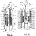
- FIGS. 9 and 10 show the automatic lock 110 with the first and second capture elements 210 and 212 in the capture position and the release position, to facilitate a description of the shift between the capture position and the release position.
- FIG. 11 illustrates a perspective view of some internal parts of the automatic lock 110 to further explain certain aspects of operation of the automatic lock 110.
- the housing 200 (or at least one half thereof) includes receiving tracks 240 for the first and second capture elements 210 and 212.
- receiving tracks 240 there is one instance of receiving tracks 240 on each lateral side of the housing 200 and the receiving tracks 240 form a void space inside which the first and second capture elements 210 and 212 can move upward and downward.
- the first and second capture elements 210 and 212 each include a ramp surface 250 at a distal end thereof.
- the ramp surfaces 250 are angled to face away from each other, and are located on a projection 252 that is capable of engaging the bolt 100 when the projections 252 of the first and second capture elements 210 and 212 extend out of the housing 200.
- the first and second capture elements 210 and 212 each also include a longitudinally extending retaining slot 254 inside which a biasing member (e.g., spring 256) is located.
- the springs 256 extend from the projection 252 to a stop member 260 that is located in the receiving tracks 240 of the housing 200.
- any upward movement of one either one of the projections 252 in the corresponding one of the receiving tracks 240 may cause the spring 256 in the corresponding retaining slot 254 to be compressed between the projection 252 and the stop member 260.
- the spring 256 will unload itself and move the projection downward (in a direction opposite the direction of arrow 214).
- the bolt 100 may initially contact the ramp surface 250 of the second capture element 250 (at a position of the bolt 100 shown by dashed circle 272). The bolt 100 will then ride (e.g., due to the weight of the door body 54 and corresponding momentum cause be gravity acting on the door body 54) along the ramped surface 250 and will overcome the spring 256 to compress the spring 256 as the second capture element 212 moves upwardly into the housing 200 along the receiving track 240.
- the bolt 100 will then pass by the second capture element 212 and into the space between the first and second capture elements 210 and 212 and strike the side of the first capture element 210 that is opposite the ramped surface 250 of the first capture element 210 thereby stopping movement of the door body 54 in the direction of arrow 270. Meanwhile, the spring 256 will unload after the bolt 100 clears the second capture element 210 and the projection 252 of the second capture element 212 will move downward (in a direction opposite arrow 214) to return to the position shown in FIGS. 7 and 8 .
- the second capture element 212 will deflect the bolt 100 rearward to retain the bolt 100 in the space between the first and second capture elements 210 and 212.
- the magnets 120 and 122 will cause the movement of the door body 54 to stop and the bolt 100 will be retained at the location shown by dashed circle 276.
- FIG. 10 illustrates the automatic lock 110 fully in the release position.
- movement of the motor 130 may cause corresponding movement of a carrier assembly 300 of the automatic lock 110.
- the carrier assembly 300 may be operably coupled to the motor 130 at a proximal end thereof, and may be operably coupled to the first and second capture elements 210 and 212 (while extending therebetween) at a distal end of the carrier assembly 300.
- the distal end of the carrier assembly 300 may include lift arms 310 that engage a portion of the first and second capture elements 210 and 212 and retain the first and second capture elements 210 and 212 in the receiving tracks 240 against the force of the springs 256 (which would otherwise force the first and second capture elements 210 and 212 out of the housing 200.
- the carrier assembly 300 further includes a slot 320, a ramp 322 and a retaining well 324.
- the slot 320, the ramp 322 and the retaining well 324 may each extend along a longitudinal centerline of the carrier assembly 300.
- a holding bolt 330 may be retained by the housing 200, and may have a ball member 332 facing internally (toward the carrier assembly 300).
- the ball member 332 may be configured to ride in the slot 320 when the carrier assembly 300 is located in a position that corresponds to the capture position (shown in FIG. 9 ). This may represent the farthest downward travel of the carrier assembly 300, and the carrier assembly 300 may be moved to this position by the motor 130.
- the motor 130 may operate to draw the automatic lock 110 out of the capture position and into the release position (shown in FIG. 10 ).
- the motor 130 may therefore draw the proximal end of the carrier assembly 300 upward (as shown by arrow 340 in FIG. 10 ) and correspondingly also carry the first and second capture elements 210 and 212 upward to retract them inside the housing 200.
- the ball member 332 may slide along the ramp 322 and into the retaining well 324 as the motor 130 draws the carrier assembly 300 upward relative to the housing 200.
- the motor 130 may stop operation in order to limit the power consumed by the motor 130.
- the motor 130 does not stay on through the entire cycle can save power and therefore extend the life of a battery, if the power supply 132 is a battery. Although the power of the motor 130 is off, and the springs 256 are compressed, the interaction between the retaining well 324 and the ball member 322 may hold the carrier assembly 300 in the release position shown in FIG. 10 .
- the carrier assembly 300 When the motor 130 is operated to transition the automatic lock 110 to the capture position (of FIG. 9 ), responsive to receipt of the closing trigger, the carrier assembly 300 is moved downward (in a direction opposite that of arrow 340). The downward movement pushes the ball member 332 out of the retaining well 324 and onto the ramp 322. When the ball member 332 reaches the ramp 322, the springs 326 may push against the stop member 260 and unload to extend the first and second capture elements 210 and 212 back to the capture position of FIG. 9 . As an alternative to the ball member 332, other spring loaded or energy storing devices may be employed.
- any spring loaded catch that fits into a detent may be employed including a ball plunger, a plastic or Delrin feature molded into an assembly to fit into a detent on a separate puller piece, a flat metal piece attached to a spring that interferes with a detent on the outside of a puller assembly, etc.
- the motor 130 may operate responsive to instructions from the controller 140, and the controller 140 may receive the opening trigger and closing trigger from the vehicle detector 150 and the motion detector 160, respectively.
- the vehicle detector 150 may take numerous forms.
- the vehicle detector 150 may be wireless detector in some cases. In such examples, the vehicle detector 150 may detect the robotic vehicle 10 without any physical contact between the robotic vehicle 10 and the selectively operable door 50.
- the vehicle detector 150 may require physical contact for detection of the robotic vehicle 10, so the vehicle detector 150 may be considered to be a mechanical or physical detector.
- a physical detector may include the provision of a mechanical switch on each side of the selectively operable door 50.
- the interface member 58 of FIG. 2 may be an example of a physical detector since the interface member 58 may be actuated when contact is made with the robotic vehicle 10. Effectively, the interface member 58 may act as a mechanical switch that is triggered when the robotic vehicle 10 engages the interface member 58.
- the switch may be synchronized to the controller 140 in the door body 54 (thereby providing the opening trigger) to enable the controller 140 to direct the motor 130 to operate the automatic lock 110 as described above to shift the first and second capture elements 210 and 212 to the release position when contact is detected.
- the controller 140 may receive the closing trigger, and may instruct the motor 130 to operate in the reverse direction (e.g., as described above) to transition the automatic lock 110 to the capture position.
- a predetermined amount e.g. 30 degrees
- the controller 140 may receive the closing trigger, and may instruct the motor 130 to operate in the reverse direction (e.g., as described above) to transition the automatic lock 110 to the capture position.
- a predetermined amount e.g. 30 degrees
- the controller 140 may receive the closing trigger, and may instruct the motor 130 to operate in the reverse direction (e.g., as described above) to transition the automatic lock 110 to the capture position.
- the interface member 58 could also take other physical forms at the door body 54 (or proximate thereto) and may be
- the interface member 58 may be an open electrical circuit that is closed by physical contact with the robotic vehicle 10.
- electrical contacts may be provided at the interface member 58 to interact with an electrically conductive portion or strip on the front of the robotic vehicle 10.
- the open circuit of the interface member 58 may be closed to provide the opening trigger to the controller 140 to transition the automatic lock 110 to the release position as discussed above.
- the automatic lock 110 may also shift back to the capture position as also described above.
- FIG. 12 illustrates a block diagram of example structures that may be employed to provide a wireless detector for the vehicle detector 150 of some example embodiments.
- the components shown in FIG. 12 are merely examples of some components that may be used in connection with some example embodiments. Other structures are also possible. Moreover, some embodiments may use fewer than all of the components shown in FIG. 12 and/or may use selected ones of such components in any combination. Other components may also be substituted or added to those shown in FIG. 12 in some cases.
- the robotic vehicle 10 may include control circuitry 12, as discussed above.
- the vehicle detector 150 may include processing circuitry 400, which may be similar in form and/or function to the control circuitry 12 of the robotic vehicle 10, for example, insofar as each may include a processor and memory that may be programmable to define corresponding operable functions of the respective devices.
- the control circuitry 12 and processing circuitry 400 may each be configured to perform data processing or control function execution and/or other processing and management services according to an example embodiment of the present invention.
- the control circuitry 12 and processing circuitry 400 may each be embodied as a chip or chip set.
- control circuitry 12 and processing circuitry 400 may comprise one or more physical packages (e.g., chips) including materials, components and/or wires on a structural assembly (e.g., a baseboard).
- the structural assembly may provide physical strength, conservation of size, and/or limitation of electrical interaction for component circuitry included thereon.
- the control circuitry 12 and processing circuitry 400 may therefore, in some cases, be configured to implement an embodiment of the present invention on a single chip or as a single "system on a chip.”
- a chip or chipset may constitute means for performing one or more operations for providing the functionalities described herein.
- the control circuitry 12 and processing circuitry 400 may include one or more instances of a processor and memory.
- the processing circuitry 400 of the vehicle detector 150 may be shared with or distinct from corresponding processing circuitry of the controller 140.
- the processing circuitry 400 of the vehicle detector 150 may include or otherwise be in communication with (e.g., may be operably coupled to) a transmitter 410 and/or receiver 420.
- the control circuitry 12 of the robotic vehicle 10 may include or otherwise be in communication with (e.g., may be operably coupled to) a transmitter 430 and/or receiver 440.
- the interactions and structures used to embody selective ones of these transmitters and receivers may define a number of different specific ways that the vehicle detector 150 may be defined as a wireless detector.
- the wireless detector may be embodied as a Bluetooth or Bluetooth Low Energy (BLE) detector.
- the transmitter 430 of the robotic vehicle 10 may transmit a relatively low power signal (e.g., Bluetooth or other low power signals) that is detectable by the receiver 420 of the vehicle detector 150 when the robotic vehicle 10 is within range.
- the distance at which the low power signal is detectable may be adjustable by adjusting the power level of the transmitter 430.
- the receiver 420 of the vehicle detector 150 may have a predefined signal detection threshold (e.g., a certain received signal strength indicator (RSSI) that is sufficient to be considered as an opening trigger.
- RSSI received signal strength indicator
- the receiver 420 may either be configured to generate the opening trigger responsive to any receipt of the low power signal, or only responsive to receipt of the low power signal above a predefined threshold.
- the transmitter 430 may further be shielded (e.g., on sides and the rear of the robotic vehicle 10) so that the signal transmitted is strongest directly in front of the robotic vehicle 10.
- the robotic vehicle 10 may pass close to the selectively operable door 50 without triggering an unlock event unless the robotic vehicle 10 is headed directly (or nearly directly) toward the selectively operable door 50.
- the shielding may therefore provide a type of angle of approach (AOA) detection may be a further component of the process used to generate the opening trigger.
- AOA detection paradigm may be employed by making the receiver 420 at the vehicle detector 150 capable of discerning AOA based on signal reception.
- the receiver 420 may actually be embodied by two spaced apart receivers located at the door body 54 (or door frame 52) in different parts thereof.
- the signal received from the transmitter 430 may therefore be received at slightly different times based on the AOA, and the timing difference may be used to calculate the AOA. If the AOA is outside a certain range (e.g., a range of values indicating likely intent of the robotic vehicle 10 to pass through the selectively operable door 50), then no opening trigger may be initiated. However, if the AOA is within the certain range of values, then the opening trigger may be initiated.
- a certain range e.g., a range of values indicating likely intent of the robotic vehicle 10 to pass through the selectively operable door 50
- the opening trigger may be initiated.
- the wireless detector may alternatively be embodied as a radio frequency identifier (RFID) reader in some cases.
- the transmitter 410 of the vehicle detector 150 may be configured to transmit a signal that may be received (e.g., by receiver 440) at a passive RFID tag on the robotic vehicle 10.
- the RFID tag may respond to the signal received by transmitting, and the transmission from the RFID tag may be received by the receiver 420 of the vehicle detector 150 indicating the presence of the robotic vehicle 10 within a short distance of the selectively operable door 50 to generate the opening trigger.
- the RFID tag may be an active tag instead of a passive tag.
- an RFID reader may be in the door frame 52 or the door body 54 and may read the RFID tag as the robotic vehicle 10 approaches the selectively operable door 50 to generate the opening trigger.
- the robotic vehicle 10 may have two passive or active RFID tags located thereat. Each of the two RFID tags may have a unique identity or identifier, and may be placed on opposite sides (e.g., right and left) of the robotic vehicle 10. As the robotic vehicle 10 approaches the selectively operable door 50, the vehicle detector 150 may record a difference in the time that the signals were received from each of the RFID tags in order to determine the AOA based on the time difference.
- the two RFID tags could be located at the selectively operable door 50 and the reader may be located at the robotic vehicle 10. In such alternative, the calculation may be similarly performed to generate AOA, except that the roles and locations of the components involved in the calculation are reversed.
- the wireless detector may be embodied as a time of flight (TOF) sensor.
- TOF time of flight
- each side of the door body 54 may have an instance of the transmitter 410 thereon (or the transmitter 410 may be omni or bi-directional).
- the transmitter 410 may generate a signal that bounces off the robotic vehicle 10 and is returned and received at the receiver 420.
- the TOF may be calculated and a range may be determined from the calculation. If the range is decreasing at a rate that indicates that the robotic vehicle 10 is heading toward the selectively operable door 50, the opening trigger may be generated.
- AOA may be integrated into the calculation by using a known speed of the robotic vehicle 10, and the rate at which range is decreasing to the selectively operable door 50.
- the AOA can be determined to see if the approach of the robotic vehicle 10 is direct, and therefore more likely to be made with intent to pass through the selectively operable door 50 rather than simply performing a cutting operation in the vicinity of the selectively operable door 50.
- wireless detection may be accomplished via a combination of components that accurately track the location of the robotic vehicle 10.
- the robotic vehicle 10 may include a location module 450 configured to accurately determine the location of the robotic vehicle 10.
- the location module 450 may be a GPS receiver or may employ real time kinematic (RTK) GPS positioning or any other suitable means by which to accurately obtain location information in real time (e.g., GPS, GLONASS, Galileo, GNSS, and/or the like).
- the location information may then be transmitted (e.g., via transmitter 430) to the receiver 420 of the vehicle detector 150.
- the vehicle detector 150 may then (e.g., via the processing circuitry 400) determine whether the robotic vehicle 10 is intended to pass through the selectively operable door 50 and cause a transition to the release condition, as described above.
- the communication from the transmitter 430 to the receiver 420 may be direct or indirect.
- a wireless network component e.g., a WiFi/Bluetooth/cellular connection via a hotspot, access point, cell site, or the like
- a wireless network component e.g., a WiFi/Bluetooth/cellular connection via a hotspot, access point, cell site, or the like
- wireless detection may be accomplished visually.
- the vehicle detector 150 may be embodied as or include a camera 460, and the camera 460 may enable visual recognition techniques to be employed to act as the opening trigger.
- one or more cameras may be mounted at the selectively operable door 50.
- the camera 460 may be configured to initiate the opening trigger responsive to visually identifying the robotic vehicle 10 in a specific location or on a recognized trajectory that, in either case, is understood to have a high probability of corresponding to an intent of the robotic vehicle 10 to pass through the selectively operable door 50.
- the camera 460 may have a focus point that is relatively close to the selectively operable door 50, and the camera 460 may be configured to read indicia that may be provided on a body of the robotic vehicle 10. If the robotic vehicle 10 is at the focus point and the indicia is readable, it may be clear that the robotic vehicle 10 has moved toward the selectively operable door 50 with the intent to pass through.
- the camera 460 may, in some cases, be located in the interface member 58. However, the camera 460, if employed, could also be at other locations on or near the selectively operable door 50.
- the opening trigger may be initiated via magnetic triggering.
- the interface member 58 or another portion of the selectively operable door 50 may include a Hall effect sensor or magnetic reed switch.
- the robotic vehicle 10 may emit a magnetic field over a relatively short range (e.g., to keep power level and battery consumption low, or to facilitate use of small permanent magnets).
- the magnetic emitter of the robotic vehicle 10 may be considered as the transmitter 430 of FIG. 12 . If the robotic vehicle 10 moves close enough to the selectively operable door 50 to enable the receiver 420 (e.g., Hall effect sensor or magnetic reed switch) of the vehicle detector 150 to detect the magnetic field emitted by the robotic vehicle 10, the opening trigger may be initiated.
- the receiver 420 e.g., Hall effect sensor or magnetic reed switch
- the transmitter 430 and receiver 440 may be portions of an internal electronic communication system and/or execute an internal electronic communication protocol inside the robotic vehicle 10.
- a system/protocol may include a universal asynchronous receiver-transmitter (UART).
- UART universal asynchronous receiver-transmitter
- the internal electronic communication system may be configured to follow a guide wire to the selectively operable door 50.
- the robotic vehicle 10 may clearly be headed toward the selectively operable door 50 for passage therethrough.
- the internal electronic communication system may have corresponding predetermined conditions associated therewith, which may cause generation of the opening trigger.
- the opening trigger for the selectively operable door 50 may be generated when the robotic vehicle 10 is following the guide wire.
- the selectively operable door 50 may be configured to minimize power consumption by operating the motor 130 only to transition the automatic lock 110 to the release position.
- the design of the automatic lock 110 causes the release position to be held without any power consumption by the motor 130 until an actual event associated with movement of the robotic vehicle 10 through the selectively operable door 50 (e.g., swinging of the door body 54 of a predetermined amount) causes the motor 130 to operate again only long enough to return the automatic lock 110 to the release position.
- an actual event associated with movement of the robotic vehicle 10 through the selectively operable door 50 e.g., swinging of the door body 54 of a predetermined amount
- a timing circuit 470 may be provided at the vehicle detector 150 and if the opening trigger is received, the timing circuit 470 may begin to count for a threshold amount of time. When the threshold amount of time has elapsed, if the door body 54 has not moved sufficient to initiate a release trigger, the timing circuit 470 may provide a signal to the controller 140 and the controller 140 may cause the motor 130 to operate to transition the automatic lock 110 to the capture position to ensure that the door body 54 is no longer free to move.
- the robotic vehicle 10 may be configured to overtly signal an intent to transition through the selectively operable door 50.
- the transmitter 430 of the robotic vehicle 430 may only be powered and therefore enabled to transmit (regardless of the type of transmission) when the robotic vehicle 10 intends to transit through the selectively operable door 50.
- Movement of the door body 54 may then be detected (e.g., instead of detecting any door position itself) to transition from release position to capture position.
- the movement of the door body 54 may be accomplished via an accelerometer.
- sensors could alternatively be employed to sense door movement, door location relative to the frame or displacement including, for example, magneto resistive sensors, Hall effect sensors, inductive sensors, infrared sensors, optical sensors, physical switches, or RFID tags or other near field communication (NFC) tags.
- the sensors may be specifically tailored to detecting door angle or detecting rotation of the door.
- Such sensors may include, for example, potentiometers (e.g., rotary on the axis or hinge of the door body 54 or linear potentiometers on a spring loaded plunger with a cam to show relative degree of rotation), momentary plunger switch with a cam to trigger on a specific angle or range of angles, optical angular sensors, mechanical rotary sensors, angular Hall effect sensors, a mercury angle switch, or inertial measurement units (IMU) such as magnetometer or gyroscope.
- potentiometers e.g., rotary on the axis or hinge of the door body 54 or linear potentiometers on a spring loaded plunger with a cam to show relative degree of rotation
- momentary plunger switch with a cam to trigger on a specific angle or range of angles optical angular sensors
- mechanical rotary sensors angular Hall effect sensors
- mercury angle switch a mercury angle switch
- IMU inertial measurement units
- a selectively operable door for passage of a robotic vehicle may be provided.
- the selectively operable door may include a door frame disposable in a barrier dividing two areas in which the robotic vehicle is enabled to travel, a door body hingedly connected to the door frame, and a latching assembly configured to alternately allow movement of the door body such that the robotic vehicle to enabled to pass through the selectively operable door via displacement of the door body and prevent movement of the door body such that the door body is retained in a closed state.
- the latching assembly may include an automatic lock configured to define a release position in which movement of the door body from the closed state is allowed, and a capture position in which movement of the door body to the closed state is allowed and movement of the door body from the closed state is prevented.
- the selectively operable door of some embodiments may include additional features, modifications, augmentations and/or the like to achieve further objectives or enhance performance of the selectively operable door.
- the additional features, modifications, augmentations and/or the like may be added in any combination with each other.
- the automatic lock may be disposed at the door body and a bolt of the latching assembly extends from the door frame toward the automatic lock.
- the automatic lock may include a first capture element and a second capture element.
- the first and second capture elements may extend on opposite sides of the bolt when the door body is in the closed state, and the first and second capture elements may be withdrawn into a housing of the automatic lock in the release position.
- each of the first and second capture elements may include a ramp surface at a distal end thereof, the ramp surfaces being angled to face away from each other. In response to the door body swinging toward the closed state while the automatic lock is in the capture position, a corresponding one of the ramp surfaces rides along the bolt to displace a respective one of the first and second capture elements toward the housing to enable the door body to return to the closed state.
- the first and second capture elements may be biased toward the extended position, and a carrier assembly operable by a motor may overcome the biasing of the first and second capture elements to transition the automatic lock to the release position.
- the carrier assembly may include a retaining well configured to interface with a ball member to hold the automatic lock in the release position until returned to the capture position by operation of the motor.
- the automatic lock may be operably coupled to a motor, which may be configured to operate the automatic lock to the release position responsive to an opening trigger and to the capture position responsive to a closing trigger.
- the motor may be configured to turn off responsive to completing a cycle to transition the automatic lock between the release position and the capture position.
- the automatic lock may be biased toward the capture position, and the automatic lock may be configured to be retained in the release position when the motor is off after the motor transitions the automatic lock to the release position.
- the motor and the automatic lock may each be disposed within the door body.
- the opening trigger may be received wirelessly via transmission of a signal from the robotic vehicle to a vehicle detector located at the door body.
- the signal is received at two locations with a time difference therebetween, and the time difference may enable a determination of an angle of approach of the robotic vehicle toward the door body.
- the opening trigger may be received wirelessly based on location information specifying a location of the robotic vehicle relative to the door body.
- the opening trigger may be received wirelessly based on reading an radio frequency identification (RFID) tag associated with the robotic vehicle.
- RFID radio frequency identification
- the opening trigger may be received wirelessly based on a receiver at the door body reading a magnetic signature generated by the robotic vehicle.
- the opening trigger may be received wirelessly from a camera detecting movement of the robotic vehicle toward the door body.
- the opening trigger may be received based on a physical interaction between a portion of the door body and the robotic vehicle.
- the physical interaction may include the robotic vehicle activating a switch located at the door body or a conductive component of the robotic vehicle closing an open circuit at the door body by contact with the door body.
- the automatic lock may be transitioned from the release position to the capture position responsive to movement of the door body by at least a predetermined amount away from the closed state.
- the door may further include a movement sensor configured to detect the movement of the door body.
- the movement sensor may include an accelerometer configured to detect at least a thirty degree movement of the door from the closed state.
Landscapes
- Engineering & Computer Science (AREA)
- Physics & Mathematics (AREA)
- Aviation & Aerospace Engineering (AREA)
- Radar, Positioning & Navigation (AREA)
- Remote Sensing (AREA)
- General Physics & Mathematics (AREA)
- Automation & Control Theory (AREA)
- Electromagnetism (AREA)
- Life Sciences & Earth Sciences (AREA)
- Environmental Sciences (AREA)
- Power-Operated Mechanisms For Wings (AREA)
Description
- Example embodiments generally relate to robotic vehicles and, more particularly, relate to a door that selectively operates to enable a robotic vehicle to pass through.
- Yard maintenance tasks are commonly performed using various tools and/or machines that are configured for the performance of corresponding specific tasks. Certain tasks, like grass cutting, are typically performed by lawn mowers. Lawn mowers themselves may have many different configurations to support the needs and budgets of consumers. Walk-behind lawn mowers are typically compact, have comparatively small engines and are relatively inexpensive. Meanwhile, at the other end of the spectrum, riding lawn mowers, such as lawn tractors, can be quite large. More recently, robotic mowers and/or remote controlled mowers have also become options for consumers to consider.
- Robotic mowers are typically confined to operating on a parcel of land that is bounded by some form of boundary (e.g., defined by a wire or other methods). The robotic mower is capable of detecting the boundary and operating relatively autonomously within the area defined by the boundary. However, in some cases, a physical boundary (e.g., a fenced in yard or portion thereof) may only be part of the operating area inside which the robotic mower is intended to operate. For example, while front yards or traditionally not fenced in, a back yard may indeed be fenced in. Meanwhile, it may be desirable for the robotic mower to operate within both the front yard and the back yard. In a situation like this, or in other situations where it may be desirable to have the robotic mower pass from one area to another without sacrificing the security, privacy or integrity of a barrier such as a wall or fence.
-
US 10,159,181 B2 - Some example embodiments may therefore provide a selectively operable door for passage of a robotic vehicle. According to the subject-matter of
claim 1 there is provided a selectively operable door for passage of a robotic vehicle, the selectively operable door comprising a door frame disposable in a barrier dividing two areas in which the robotic vehicle is enabled to travel, a door body hingedly connected to the door frame; and a latching assembly configured to alternately allow movement of the door body such that the robotic vehicle to enabled to pass through the selectively operable door via displacement of the door body and prevent movement of the door body such that the door body is retained in a closed state, wherein the latching assembly comprises an automatic lock configured to define a release position in which movement of the door body from the closed state is allowed, and a capture position in which movement of the door body to the closed state is allowed and movement of the door body from the closed state is prevented, wherein the automatic lock is disposed at the door body and a bolt of the latching assembly extends from the door frame toward the automatic lock, wherein the automatic lock comprises a first capture element and a second capture element, wherein the first and second capture elements extend on opposite sides of the bolt when the door body is in the closed state, and wherein the first and second capture elements are withdrawn into a housing of the automatic lock in the release position. - Having thus described the invention in general terms, reference will now be made to the accompanying drawings, which are not necessarily drawn to scale, and wherein:
-
FIG. 1 illustrates an example operating environment for a robotic vehicle of an example embodiment; -
FIG. 2 illustrates a fence in which a selectively operable door of an example embodiment is located; -
FIG. 3 illustrates a block diagram of various components that may be employed as part of a selectively operable door in accordance with an example embodiment; -
FIG. 4 illustrates a side view of portions of a door frame, motor and automatic lock of the selectively operable door in accordance with an example embodiment; -
FIG. 5 illustrates a perspective view of a automatic lock in a capture position according to an example embodiment; -
FIG. 6 illustrates a perspective view of the automatic lock transitioning to a release position according to an example embodiment; -
FIG. 7 shows a perspective view of the automatic lock in isolation according to an example embodiment; -
FIG. 8 shows the automatic lock with half of the housing thereof removed in accordance with an example embodiment; -
FIG. 9 shows the automatic lock with half of the housing removed to show internal components thereof in the capture position in accordance with an example embodiment; -
FIG. 10 shows the automatic lock with half of the housing removed to show internal components thereof in the release position in accordance with an example embodiment; -
FIG. 11 is a perspective view of internal components of the automatic lock in isolation in accordance with an example embodiment; and -
FIG. 12 is a block diagram of various components of a robotic vehicle and vehicle detector in accordance with an example embodiment. - Some example embodiments now will be described more fully hereinafter with reference to the accompanying drawings, in which some, but not all example embodiments are shown. Indeed, the examples described and pictured herein should not be construed as being limiting as to the scope, applicability or configuration of the present claims.
- Rather, these example embodiments are provided so that this disclosure will satisfy applicable legal requirements. Like reference numerals refer to like elements throughout. Furthermore, as used herein, the term "or" is to be interpreted as a logical operator that results in true whenever one or more of its operands are true. Additionally, the term "yard maintenance" is meant to relate to any outdoor grounds improvement or maintenance related activity and need not specifically apply to activities directly tied to grass, turf or sod care. As used herein, operable coupling should be understood to relate to direct or indirect connection that, in either case, enables functional interconnection of components that are operably coupled to each other.
- Robotic mowers, which are one example of a robotic vehicle of an example embodiment, typically mow an area that is defined by a boundary that bounds the area to be mowed. The robotic mower roams within the bounded area to ensure that the entire area is mowed, but the robotic mower does not go outside of the bounded area. When operating in a fenced in area, the fence could form the boundary either actually or by virtue of having a boundary wire buried proximate to the fence. However, if the robotic mower needs to exit the fenced in area for any reason several issues may arise. First, a breach may be required in the fence to enable the robotic mower to leave the fenced in area. Second, if some type of door is used to avoid defining a breach, the door may not be secure, or otherwise may require manual operation that inhibits operation of the robotic mower. If the door is automated with respect to opening, the amount of power consumption that is generated by unlocking the door when the robotic mower comes near without intending to go through the door can lead to excessive battery drain or other waste of power.
- Example embodiments may provide a selectively operable door that makes it possible to preserve the integrity and continuity of the fence with respect to enclosing the fenced in area by avoiding introduction of a non-secure portion of the fence. Example embodiments may also enable the robotic vehicle (e.g., robotic mower) to easily (and autonomously) pass through the fence (i.e., via the selectively operable door) to reach other service areas and/or a charging station of the robotic vehicle. Additionally, example embodiments may provide operability of the door in such a way that minimizes the incidence of false positive or unnecessary unlock cycles for the door.
- Although a robotic mower is one example of a device that may employ the selectively operable door of an example embodiment, it should be noted that other robotic vehicles may also work in connection with such a device. For example, robotic vehicles that are configured as mobile sensing devices, watering devices, fertilizing devices, spraying/spreading machines, and/or the like) may also use example embodiments. In this regard, while the robotic vehicle operates within boundaries (which can be defined by any of a number of different ways), the robotic vehicle may perform a function, and may be intelligent enough to avoid (and possibly even classify) objects it encounters by employing contactless sensors, while further enabling the robotic vehicle to navigate through a doorway into a physically separated portion of a parcel that is serviced by the robotic vehicle. By enabling the robotic vehicle to accurately determine its position and experience its surroundings, including interactions with a selectively operable door, some example embodiments may greatly expand the capabilities and the performance of robotic vehicles.
- A boundary wire may be one way to define the boundary. However, since a boundary wire can be difficult to install in some areas, other strategies may be employed in some cases. For example, global positioning system (GPS), dead reckoning, local positioning beacons, physical boundaries or even visual fixing relative to various structural markers may alternatively be employed to locate and retain the robotic vehicle within the boundary. A robotic vehicle may therefore be provided that can operate and stay within boundaries that can be defined by any of a number of different ways. Moreover, the robotic vehicle may be intelligent enough to pass through a door into a physically separated portion of a service area.
-
FIG. 1 illustrates an example operating environment for arobotic vehicle 10 that may be employed as a deicing robot in connection with an example embodiment. However, it should be appreciated that example embodiments may be employed on numerous other robotic vehicles, so therobotic vehicle 10 should be recognized as merely one example of such a vehicle. Therobotic vehicle 10 may operate to mow grass in a service area 20 (i.e., a parcel of land on which therobotic vehicle 10 is operable). Theservice area 20 includes afirst portion 22 and asecond portion 24 that are physically separated from each other. In this example, thefirst portion 22 is a back yard that is enclosed by a first boundary, which is afence 30. Notably, a structure 32 (e.g., a house or other building) may also form part of the first boundary. - The first boundary may be defined using one or more physical boundaries (e.g., the
fence 30, wall, curb, building, boundary wire and/or the like), or programmed location based boundaries or combinations thereof. When thefirst boundary 30 is detected, by any suitable means, therobotic vehicle 10 may be informed so that therobotic vehicle 10 can operate in a manner that prevents therobotic vehicle 10 from leaving or moving outside theboundary 30. - In the example of
FIG. 1 , theservice area 20 also includes asecond portion 24, which may be a front yard (which is not fenced in this example). As noted above, a portion of the fence 30 (and the structure 32) separates thefirst portion 22 from thesecond portion 24 of theservice area 20. Thesecond portion 24 of theservice area 20 may be enclosed by asecond boundary 34. Thesecond boundary 34 in this example may be a boundary wire. However, as noted above, other means of defining thesecond boundary 34 may be used in some cases. Moreover, it should be understood that if thesecond boundary 34 and the first boundary are both defined by boundary wires, the boundary wires could be the same continuous boundary wire or different boundary wires in alternative examples. - The
robotic vehicle 10 may be controlled, at least in part, viacontrol circuitry 12 located onboard therobotic vehicle 10. Thecontrol circuitry 12 may include, among other things, a positioning module and a sensor module, which will be described in greater detail below. Accordingly, therobotic vehicle 10 may utilize thecontrol circuitry 12 to define a path (e.g., which may be random in some cases) for coverage of theservice area 20 in terms of performing a task over the first andsecond portions service area 20. In this regard, the positioning module may be used to guide therobotic vehicle 10 over theservice area 20 and to ensure that full coverage (of at least predetermined portions of the service area 20) is obtained, while the sensor module may detect objects and/or gather data regarding the surroundings of therobotic vehicle 10 while theservice area 20 is traversed. - If a sensor module is employed, the sensor module may include a sensors related to positional determination (e.g., a GPS receiver, an accelerometer, a camera, a radar transmitter/detector, an ultrasonic sensor, a laser scanner and/or the like). Thus, for example, positional determinations may be made using GPS, inertial navigation, optical flow, radio navigation, visual location (e.g., VSLAM) and/or other positioning techniques or combinations thereof. Accordingly, the sensors may be used, at least in part, for determining the location of the
robotic vehicle 10 relative to boundaries or other points of interest (e.g., a starting point or other key features) of theservice area 20, or determining a position history or track of therobotic vehicle 10 over time. The sensors may also detect collision, tipping over, or various fault conditions. In some cases, the sensors may also or alternatively collect data regarding various measurable parameters (e.g., moisture, temperature, soil conditions, etc.) associated with particular locations on theservice area 20. - In an example embodiment, the
robotic vehicle 10 may be battery powered via one or more rechargeable batteries. Accordingly, therobotic vehicle 10 may be configured to return to a chargingstation 40 that may be located at some position on theservice area 20 in order to recharge the batteries. The batteries may power a drive system and a blade control system (or other functional element) of therobotic vehicle 10. However, thecontrol circuitry 12 of therobotic vehicle 10 may selectively control the application of power or other control signals to the drive system and/or the blade control system to direct the operation of the drive system and/or blade control system. Accordingly, movement of therobotic vehicle 10 over theservice area 20 may be controlled by thecontrol circuitry 12 in a manner that enables therobotic vehicle 10 to systematically or randomly traverse theservice area 20 while operating the blade control system to mow grass (or otherwise service) theservice area 20. - The charging
statin 40 may be disposed on either thefirst portion 22 or thesecond portion 24 of theservice area 20. Thus, the fact that the charging station is in thefirst portion 22 inFIG. 1 should not be seen as limiting in any way. In order to enable the chargingstation 40 from operating on thesecond portion 24, therobotic vehicle 10 must have a way to pass between thefirst portion 22 and thesecond portion 24. Accordingly, a selectively operable door 50 (or simply "door") of an example embodiment may be provided in thefence 30. However, it should also be appreciated that the chargingstation 40 could be located in thestructure 32, and the selectivelyoperable door 50 may then be located in a wall of thestructure 32. -
FIG. 2 illustrates a perspective view of the selectivelyoperable door 50 of an embodiment located in situ in thefence 30. Thefence 30 in this example is made of a series of vertical and horizontal beams or bars. However, thefence 30 could take any form in alternative embodiments, and may be made of any material. The selectivelyoperable door 50 may be disposed in a portion of thefence 30 proximate to the ground in order to enable therobotic vehicle 10 to drive through the selectively operable door 50 (and therefore also through the fence 30) without difficulty or interference. - As shown in
FIG. 2 , the selectivelyoperable door 50 includes a number of physical components including adoor frame 52 and adoor body 54 that is hingedly attached to thedoor frame 52. Thedoor body 54 is hingedly attached to a top or cross member of thedoor frame 52. The top or cross member of thedoor frame 52 may extend between two parallel door jambs on opposing sides of thedoor body 54. Thedoor frame 52 may include a bottom member in some cases, but such bottom member is not required. Thus, thedoor body 54 may extend nearly to the ground or to the ground in some cases. If a bottom member is employed, the bottom member may be relatively thin (or ramped with a slight incline) to enable therobotic vehicle 10 to transit over the bottom member relatively easily. - In an example embodiment, the
door body 54 may include aninterface member 58 attached to each opposing side of the door body 54 (i.e., oneinterface member 58 facing thefirst portion 22 and oneinterface member 58 facing thesecond portion 24 of the service area 20). Theinterface member 58 may be used for one or more different functional interactions with therobotic vehicle 10. For example, in a simple case, theinterface member 58 may be (or include) one or more rollers. In such an example, therobotic vehicle 10 may, when passing through the selectivelyoperable door 50, contact theinterface member 58 for minimizing any damage or friction with a body of therobotic vehicle 10. The rollers may therefore ensure that the physical appearance and exterior of the body of therobotic vehicle 10 does not become excessively damaged, marred or scratched. In other examples, theinterface member 58 may have additional or alternative functions (as discussed in greater detail below). -
FIG. 3 illustrates a block diagram of the selectivelyoperable door 50 of an embodiment. The selectivelyoperable door 50 includes a latching assembly that is configured to alternately lock to prevent opening of the selectivelyoperable door 50 and unlock to permit therobotic vehicle 10 to pass through the selectivelyoperable door 50. The latching assembly may include components that may be embodied in a number of different ways. In the embodiment shown inFIG. 3 , thedoor frame 52 has abolt 100 extending therefrom toward thedoor body 54, to engage anautomatic lock 110 disposed at thedoor body 54. Theautomatic lock 110 and thebolt 100 therefore form the latching assembly (or portions thereof) in this embodiment. In some cases, theautomatic lock 110 may be inside thedoor body 54, and have portions thereof that are exposed to receive thebolt 100 when aligned therewith. However, it should be appreciated that theautomatic lock 110 could alternatively be completely or partially located outside thedoor body 54. The locations of thebolt 100 andautomatic lock 110 could also be reversed in some examples. In either case, when thedoor body 54 is in a closed state relative to thedoor frame 52, theautomatic lock 110 and thebolt 100 align with each other so that theautomatic lock 110 can capture or retain the bolt 100 (e.g., in a locked or captured state). - In some examples, a
magnet 120 may be disposed at a portion of thedoor body 54 that aligns with anothermagnet 122 disposed in thedoor frame 52 when thedoor body 54 is in the closed state. Accordingly, as thedoor body 54 swings (either freely or resisted by spring force), themagnets door body 54 to a stop in the closed state. Theautomatic lock 110 will then also be brought into proper alignment with thebolt 100 so that operation of theautomatic lock 110 alternately captures or releases thebolt 100 as described in greater detail below to lock and unlock, respectively, thedoor body 54 with respect to thedoor frame 52. When thedoor body 54 is locked with respect to thedoor frame 52, the selectively operable door 50 (or latching assembly) may also be considered to be locked. When thedoor body 54 is unlocked with respect to thedoor frame 52, the selectively operable door 50 (or latching assembly) may be considered to be unlocked. - When the selectively
operable door 50 is unlocked, therobotic vehicle 10 may be enabled to pass through the selectivelyoperable door 50 with minimal interference by pushing thedoor body 54 to swing on the hinge that connects thedoor body 54 to thedoor frame 52. When the selectivelyoperable door 50 is locked, therobotic vehicle 10 may not be enabled to pass through the selectivelyoperable door 50, and thedoor body 54 may be prevented from swinging out of the closed state on the hinge that connects thedoor body 54 to thedoor frame 52 by virtue of theautomatic lock 110 capturing thebolt 100. - In an example embodiment, the
automatic lock 110 alternately captures or releases thebolt 100 responsive to movement of a portion of theautomatic lock 110. Theautomatic lock 110 may therefore define a release position in which thebolt 100 is released so thatdoor body 54 can be moved relative to thedoor frame 52 and a capture position in which, movement of thedoor body 54 from the closed state relative to thedoor frame 52 is prevented, but movement of thedoor body 54 to the closed state (e.g., if thedoor body 54 is displaced from the closed state) is still possible. In some cases, amotor 130 may be operably coupled to theautomatic lock 110 to drive the automatic lock 110 (or portion thereof) to alternately capture and release the bolt 100 (or at least move between respective capture and release positions that enable the capturing and releasing of thebolt 100, respectively). Themotor 130 may be an AC or DC motor that is powered from apower supply 132. In an example embodiment, thepower supply 132 may be a battery, and themotor 130 may be a DC motor (e.g., a brushless DC (BLDC) motor). However, in alternative embodiments, themotor 130 may be an AC motor and thepower supply 132 may be mains power. Thepower supply 132 may be in the door frame 52 (or otherwise external to the door body 54) and connected to themotor 130 via wires that extend between thedoor frame 52 anddoor body 54 proximate to or via the hinge. However, thepower supply 132 could alternatively be located in thedoor body 54 in some cases. - Operation of the
motor 130 may be managed by acontroller 140. Thecontroller 140 may include processing circuitry (e.g., a processor and memory) that are configurable to respond to triggers provided thereto in order to instruct themotor 130 to operate to move theautomatic lock 110 between the capture and release positions. In an example embodiment, thecontroller 140 may be operably coupled to avehicle detector 150 that is configured to provide an opening trigger to thecontroller 140 when therobotic vehicle 10 is determined to be moving toward the selectivelyoperable door 50 to pass therethrough. The opening trigger (or signal) may be an electric signal or mechanical signal as discussed in greater detail below, and thevehicle detector 150 may also take a number of forms as discussed below. Responsive to receipt of the opening trigger, thecontroller 140 may instruct themotor 130 to operate to move the automatic lock 110 (or portion thereof) to the release position. - In an example embodiment, the
motor 130 may operate to move the automatic lock 110 (or portion thereof) to the capture position responsive to instruction from thecontroller 140 when thecontroller 140 has received a closing trigger (or signal) from a door motion detector (or simply motion detector 160). Themotion detector 160 may be configured to detect movement of thedoor body 54 of at least a predetermined amount. In an example embodiment, themotion detector 160 may be an accelerometer, and the accelerometer may be configured to detect movement of thedoor body 54 of at least a predetermined amount (e.g., greater than 30 degrees of pivot about the hinge). Thus, themotion detector 160 may detect that therobotic vehicle 10 is moving through the selectivelyoperable door 50 and has displaced thedoor body 54 relative to thedoor frame 52 by the predetermined amount, and may provide the closing trigger to thecontroller 140. -
FIG. 4 illustrates a partial cutaway view of portions of the selectivelyoperable door 50 in accordance with an example embodiment. In this regard, a portion of thedoor frame 52 is shown along with the door body 54 (in dashed lines). Thedoor body 54 encloses theautomatic lock 110 and themotor 130 therein. Thedoor body 54 also includes an aperture inside which thebolt 100 may extend to be captured by theautomatic lock 110. Meanwhile, themagnets door body 54 anddoor frame 52, respectively. However, themagnets -
FIGS. 5 and6 illustrates a perspective view of theautomatic lock 110 in the capture position (FIG. 5 ) and moving toward (or in) the release position (FIG. 6 ). As shown inFIG. 5 , theautomatic lock 110 has ahousing 200 from which afirst capture element 210 and asecond capture element 212 extend. The first andsecond capture elements housing 200 to define the capture position. In this regard, when the first andsecond capture elements second capture elements FIG. 5 ). To the extent thedoor body 54 is in the closed state while the first andsecond capture elements second capture elements FIG. 5 ). - The first and
second capture elements housing 200 to transition to the release position. Thus, as shown inFIG. 6 , the first andsecond capture elements arrow 214 such that they are no longer on opposing sides of thebolt 100, and therefore theautomatic lock 110 and thedoor body 54 can move relative to thebolt 100 and thedoor frame 52, respectively. When the first andsecond capture elements second capture elements bolt 100. However, when not retracted (and therefore extended), the first andsecond capture elements bolt 100. -
FIG. 7 shows a perspective view of theautomatic lock 110 in accordance with an example embodiment.FIG. 8 illustrates theautomatic lock 110 with one half of thehousing 200 removed to reveal internal components of theautomatic lock 110 in accordance with one example embodiment.FIGS. 7 and8 will be used to describe operation of theautomatic lock 110 when thedoor body 54 returns to the closed state while the automatic lock is in the capture position. Meanwhile,FIGS. 9 and 10 show theautomatic lock 110 with the first andsecond capture elements FIG. 11 illustrates a perspective view of some internal parts of theautomatic lock 110 to further explain certain aspects of operation of theautomatic lock 110. - Referring first to
FIGS. 7 and8 , it can be seen that the housing 200 (or at least one half thereof) includes receivingtracks 240 for the first andsecond capture elements tracks 240 on each lateral side of thehousing 200 and the receivingtracks 240 form a void space inside which the first andsecond capture elements - The first and
second capture elements ramp surface 250 at a distal end thereof. The ramp surfaces 250 are angled to face away from each other, and are located on aprojection 252 that is capable of engaging thebolt 100 when theprojections 252 of the first andsecond capture elements housing 200. The first andsecond capture elements slot 254 inside which a biasing member (e.g., spring 256) is located. Thesprings 256 extend from theprojection 252 to astop member 260 that is located in the receivingtracks 240 of thehousing 200. Thus, as can be appreciated fromFIG. 8 , any upward movement of one either one of theprojections 252 in the corresponding one of the receivingtracks 240 may cause thespring 256 in thecorresponding retaining slot 254 to be compressed between theprojection 252 and thestop member 260. When any force moving theprojection 252 upward (in the direction of arrow 214) or retaining theprojection 252 in a position that compresses thespring 256 is removed, thespring 256 will unload itself and move the projection downward (in a direction opposite the direction of arrow 214). - Accordingly, for example, as shown in
FIG. 8 , if thedoor body 54 is allowed to pivot from an opened position toward the closed state (e.g., in a swinging direction shown by arrow 270), thebolt 100 may initially contact theramp surface 250 of the second capture element 250 (at a position of thebolt 100 shown by dashed circle 272). Thebolt 100 will then ride (e.g., due to the weight of thedoor body 54 and corresponding momentum cause be gravity acting on the door body 54) along the rampedsurface 250 and will overcome thespring 256 to compress thespring 256 as thesecond capture element 212 moves upwardly into thehousing 200 along the receivingtrack 240. Thebolt 100 will then pass by thesecond capture element 212 and into the space between the first andsecond capture elements first capture element 210 that is opposite the rampedsurface 250 of thefirst capture element 210 thereby stopping movement of thedoor body 54 in the direction ofarrow 270. Meanwhile, thespring 256 will unload after thebolt 100 clears thesecond capture element 210 and theprojection 252 of thesecond capture element 212 will move downward (in a direction opposite arrow 214) to return to the position shown inFIGS. 7 and8 . To the extent thebolt 100 bounces off of thefirst capture element 210 and moves in a direction opposite that ofarrow 270, thesecond capture element 212 will deflect thebolt 100 rearward to retain thebolt 100 in the space between the first andsecond capture elements magnets door body 54 to stop and thebolt 100 will be retained at the location shown by dashedcircle 276. - Notably, all of the actions described in reference to
FIGS. 7 and8 occur while theautomatic lock 110 is in the capture position. While transition toward the release position was shown and described in reference toFIG. 6 ,FIG. 10 illustrates theautomatic lock 110 fully in the release position. Moreover, it can be appreciated fromFIGS. 6 and10 that movement of themotor 130 may cause corresponding movement of acarrier assembly 300 of theautomatic lock 110. Thecarrier assembly 300 may be operably coupled to themotor 130 at a proximal end thereof, and may be operably coupled to the first andsecond capture elements 210 and 212 (while extending therebetween) at a distal end of thecarrier assembly 300. In this example, the distal end of thecarrier assembly 300 may include liftarms 310 that engage a portion of the first andsecond capture elements second capture elements tracks 240 against the force of the springs 256 (which would otherwise force the first andsecond capture elements housing 200. - The
carrier assembly 300 further includes aslot 320, aramp 322 and a retaining well 324. Theslot 320, theramp 322 and the retaining well 324 may each extend along a longitudinal centerline of thecarrier assembly 300. A holdingbolt 330 may be retained by thehousing 200, and may have aball member 332 facing internally (toward the carrier assembly 300). Theball member 332 may be configured to ride in theslot 320 when thecarrier assembly 300 is located in a position that corresponds to the capture position (shown inFIG. 9 ). This may represent the farthest downward travel of thecarrier assembly 300, and thecarrier assembly 300 may be moved to this position by themotor 130. When the opening trigger is received, as mentioned above, themotor 130 may operate to draw theautomatic lock 110 out of the capture position and into the release position (shown inFIG. 10 ). Themotor 130 may therefore draw the proximal end of thecarrier assembly 300 upward (as shown by arrow 340 inFIG. 10 ) and correspondingly also carry the first andsecond capture elements housing 200. Theball member 332 may slide along theramp 322 and into the retaining well 324 as themotor 130 draws thecarrier assembly 300 upward relative to thehousing 200. When themotor 130 has moved thecarrier assembly 300 to the position shown inFIG. 10 , themotor 130 may stop operation in order to limit the power consumed by themotor 130. The fact that themotor 130 does not stay on through the entire cycle can save power and therefore extend the life of a battery, if thepower supply 132 is a battery. Although the power of themotor 130 is off, and thesprings 256 are compressed, the interaction between the retaining well 324 and theball member 322 may hold thecarrier assembly 300 in the release position shown inFIG. 10 . - When the
motor 130 is operated to transition theautomatic lock 110 to the capture position (ofFIG. 9 ), responsive to receipt of the closing trigger, thecarrier assembly 300 is moved downward (in a direction opposite that of arrow 340). The downward movement pushes theball member 332 out of the retaining well 324 and onto theramp 322. When theball member 332 reaches theramp 322, the springs 326 may push against thestop member 260 and unload to extend the first andsecond capture elements FIG. 9 . As an alternative to theball member 332, other spring loaded or energy storing devices may be employed. For example, any spring loaded catch that fits into a detent may be employed including a ball plunger, a plastic or Delrin feature molded into an assembly to fit into a detent on a separate puller piece, a flat metal piece attached to a spring that interferes with a detent on the outside of a puller assembly, etc. - As noted above, the
motor 130 may operate responsive to instructions from thecontroller 140, and thecontroller 140 may receive the opening trigger and closing trigger from thevehicle detector 150 and themotion detector 160, respectively. Thevehicle detector 150 may take numerous forms. For example, thevehicle detector 150 may be wireless detector in some cases. In such examples, thevehicle detector 150 may detect therobotic vehicle 10 without any physical contact between therobotic vehicle 10 and the selectivelyoperable door 50. - In other examples, the
vehicle detector 150 may require physical contact for detection of therobotic vehicle 10, so thevehicle detector 150 may be considered to be a mechanical or physical detector. One such example of a physical detector may include the provision of a mechanical switch on each side of the selectivelyoperable door 50. For example, theinterface member 58 ofFIG. 2 may be an example of a physical detector since theinterface member 58 may be actuated when contact is made with therobotic vehicle 10. Effectively, theinterface member 58 may act as a mechanical switch that is triggered when therobotic vehicle 10 engages theinterface member 58. The switch may be synchronized to thecontroller 140 in the door body 54 (thereby providing the opening trigger) to enable thecontroller 140 to direct themotor 130 to operate theautomatic lock 110 as described above to shift the first andsecond capture elements motion detector 160 ofFIG. 3 detects motion of thedoor body 54 beyond a predetermined amount (e.g., 30 degrees), thecontroller 140 may receive the closing trigger, and may instruct themotor 130 to operate in the reverse direction (e.g., as described above) to transition theautomatic lock 110 to the capture position. As thedoor body 54 swings shut, one of the first orsecond capture elements FIG. 8 to resume capture of thebolt 100. Theinterface member 58 could also take other physical forms at the door body 54 (or proximate thereto) and may be located in a mechanical assembly or housing that shields theinterface member 58 from interaction with natural debris, weather or animals. - As another alternative, the
interface member 58 may be an open electrical circuit that is closed by physical contact with therobotic vehicle 10. In this regard, for example, electrical contacts may be provided at theinterface member 58 to interact with an electrically conductive portion or strip on the front of therobotic vehicle 10. When therobotic vehicle 10 hits theinterface member 58, the open circuit of theinterface member 58 may be closed to provide the opening trigger to thecontroller 140 to transition theautomatic lock 110 to the release position as discussed above. After therobotic vehicle 10 displaces the door, and the circuit is no longer closed, theautomatic lock 110 may also shift back to the capture position as also described above. -
FIG. 12 illustrates a block diagram of example structures that may be employed to provide a wireless detector for thevehicle detector 150 of some example embodiments. Notably, the components shown inFIG. 12 are merely examples of some components that may be used in connection with some example embodiments. Other structures are also possible. Moreover, some embodiments may use fewer than all of the components shown inFIG. 12 and/or may use selected ones of such components in any combination. Other components may also be substituted or added to those shown inFIG. 12 in some cases. - Referring now to
FIG. 12 , therobotic vehicle 10 may includecontrol circuitry 12, as discussed above. Thevehicle detector 150 may include processingcircuitry 400, which may be similar in form and/or function to thecontrol circuitry 12 of therobotic vehicle 10, for example, insofar as each may include a processor and memory that may be programmable to define corresponding operable functions of the respective devices. Thecontrol circuitry 12 andprocessing circuitry 400 may each be configured to perform data processing or control function execution and/or other processing and management services according to an example embodiment of the present invention. In some embodiments, thecontrol circuitry 12 andprocessing circuitry 400 may each be embodied as a chip or chip set. In other words, thecontrol circuitry 12 andprocessing circuitry 400 may comprise one or more physical packages (e.g., chips) including materials, components and/or wires on a structural assembly (e.g., a baseboard). The structural assembly may provide physical strength, conservation of size, and/or limitation of electrical interaction for component circuitry included thereon. Thecontrol circuitry 12 andprocessing circuitry 400 may therefore, in some cases, be configured to implement an embodiment of the present invention on a single chip or as a single "system on a chip." As such, in some cases, a chip or chipset may constitute means for performing one or more operations for providing the functionalities described herein. Thus, for example, thecontrol circuitry 12 andprocessing circuitry 400 may include one or more instances of a processor and memory. In some cases, theprocessing circuitry 400 of thevehicle detector 150 may be shared with or distinct from corresponding processing circuitry of thecontroller 140. - In an example embodiment, the
processing circuitry 400 of thevehicle detector 150 may include or otherwise be in communication with (e.g., may be operably coupled to) atransmitter 410 and/orreceiver 420. Similarly, thecontrol circuitry 12 of therobotic vehicle 10 may include or otherwise be in communication with (e.g., may be operably coupled to) atransmitter 430 and/orreceiver 440. The interactions and structures used to embody selective ones of these transmitters and receivers may define a number of different specific ways that thevehicle detector 150 may be defined as a wireless detector. - In one example embodiment, the wireless detector may be embodied as a Bluetooth or Bluetooth Low Energy (BLE) detector. In such an example, the
transmitter 430 of therobotic vehicle 10 may transmit a relatively low power signal (e.g., Bluetooth or other low power signals) that is detectable by thereceiver 420 of thevehicle detector 150 when therobotic vehicle 10 is within range. There may be no need for or existence of thereceiver 440 ortransmitter 410 in this particular example embodiment. The distance at which the low power signal is detectable may be adjustable by adjusting the power level of thetransmitter 430. Thereceiver 420 of thevehicle detector 150 may have a predefined signal detection threshold (e.g., a certain received signal strength indicator (RSSI) that is sufficient to be considered as an opening trigger. Thus, for example, thereceiver 420 may either be configured to generate the opening trigger responsive to any receipt of the low power signal, or only responsive to receipt of the low power signal above a predefined threshold. - In some cases, the
transmitter 430 may further be shielded (e.g., on sides and the rear of the robotic vehicle 10) so that the signal transmitted is strongest directly in front of therobotic vehicle 10. Thus, therobotic vehicle 10 may pass close to the selectivelyoperable door 50 without triggering an unlock event unless therobotic vehicle 10 is headed directly (or nearly directly) toward the selectivelyoperable door 50. The shielding may therefore provide a type of angle of approach (AOA) detection may be a further component of the process used to generate the opening trigger. Another AOA detection paradigm may be employed by making thereceiver 420 at thevehicle detector 150 capable of discerning AOA based on signal reception. In this regard, for example, thereceiver 420 may actually be embodied by two spaced apart receivers located at the door body 54 (or door frame 52) in different parts thereof. The signal received from thetransmitter 430 may therefore be received at slightly different times based on the AOA, and the timing difference may be used to calculate the AOA. If the AOA is outside a certain range (e.g., a range of values indicating likely intent of therobotic vehicle 10 to pass through the selectively operable door 50), then no opening trigger may be initiated. However, if the AOA is within the certain range of values, then the opening trigger may be initiated. - The wireless detector may alternatively be embodied as a radio frequency identifier (RFID) reader in some cases. In such an example, the
transmitter 410 of thevehicle detector 150 may be configured to transmit a signal that may be received (e.g., by receiver 440) at a passive RFID tag on therobotic vehicle 10. The RFID tag may respond to the signal received by transmitting, and the transmission from the RFID tag may be received by thereceiver 420 of thevehicle detector 150 indicating the presence of therobotic vehicle 10 within a short distance of the selectivelyoperable door 50 to generate the opening trigger. As an alternative, the RFID tag may be an active tag instead of a passive tag. In either case, an RFID reader may be in thedoor frame 52 or thedoor body 54 and may read the RFID tag as therobotic vehicle 10 approaches the selectivelyoperable door 50 to generate the opening trigger. - An example employing RFID techniques may also use the AOA techniques similar to those described above to increase accuracy. In this regard, for example, the
robotic vehicle 10 may have two passive or active RFID tags located thereat. Each of the two RFID tags may have a unique identity or identifier, and may be placed on opposite sides (e.g., right and left) of therobotic vehicle 10. As therobotic vehicle 10 approaches the selectivelyoperable door 50, thevehicle detector 150 may record a difference in the time that the signals were received from each of the RFID tags in order to determine the AOA based on the time difference. Alternatively, the two RFID tags could be located at the selectivelyoperable door 50 and the reader may be located at therobotic vehicle 10. In such alternative, the calculation may be similarly performed to generate AOA, except that the roles and locations of the components involved in the calculation are reversed. - In another example embodiment, the wireless detector may be embodied as a time of flight (TOF) sensor. In such an example, each side of the
door body 54 may have an instance of thetransmitter 410 thereon (or thetransmitter 410 may be omni or bi-directional). Thetransmitter 410 may generate a signal that bounces off therobotic vehicle 10 and is returned and received at thereceiver 420. The TOF may be calculated and a range may be determined from the calculation. If the range is decreasing at a rate that indicates that therobotic vehicle 10 is heading toward the selectivelyoperable door 50, the opening trigger may be generated. In some cases, AOA may be integrated into the calculation by using a known speed of therobotic vehicle 10, and the rate at which range is decreasing to the selectivelyoperable door 50. In this regard, by comparing the rate of range closure to the known speed of therobotic vehicle 10, the AOA can be determined to see if the approach of therobotic vehicle 10 is direct, and therefore more likely to be made with intent to pass through the selectivelyoperable door 50 rather than simply performing a cutting operation in the vicinity of the selectivelyoperable door 50. - In some embodiments, wireless detection may be accomplished via a combination of components that accurately track the location of the
robotic vehicle 10. For example, therobotic vehicle 10 may include alocation module 450 configured to accurately determine the location of therobotic vehicle 10. Thelocation module 450 may be a GPS receiver or may employ real time kinematic (RTK) GPS positioning or any other suitable means by which to accurately obtain location information in real time (e.g., GPS, GLONASS, Galileo, GNSS, and/or the like). The location information may then be transmitted (e.g., via transmitter 430) to thereceiver 420 of thevehicle detector 150. Thevehicle detector 150 may then (e.g., via the processing circuitry 400) determine whether therobotic vehicle 10 is intended to pass through the selectivelyoperable door 50 and cause a transition to the release condition, as described above. The communication from thetransmitter 430 to thereceiver 420 may be direct or indirect. Thus, for some examples, a wireless network component (e.g., a WiFi/Bluetooth/cellular connection via a hotspot, access point, cell site, or the like) may be interposed between thetransmitter 430 andreceiver 420. - As another alternative, wireless detection may be accomplished visually. For example, the
vehicle detector 150 may be embodied as or include acamera 460, and thecamera 460 may enable visual recognition techniques to be employed to act as the opening trigger. In such cases, for example, one or more cameras may be mounted at the selectivelyoperable door 50. Thecamera 460 may be configured to initiate the opening trigger responsive to visually identifying therobotic vehicle 10 in a specific location or on a recognized trajectory that, in either case, is understood to have a high probability of corresponding to an intent of therobotic vehicle 10 to pass through the selectivelyoperable door 50. However, in some cases, thecamera 460 may have a focus point that is relatively close to the selectivelyoperable door 50, and thecamera 460 may be configured to read indicia that may be provided on a body of therobotic vehicle 10. If therobotic vehicle 10 is at the focus point and the indicia is readable, it may be clear that therobotic vehicle 10 has moved toward the selectivelyoperable door 50 with the intent to pass through. Thecamera 460 may, in some cases, be located in theinterface member 58. However, thecamera 460, if employed, could also be at other locations on or near the selectivelyoperable door 50. - In some embodiments, the opening trigger may be initiated via magnetic triggering. For example, the
interface member 58 or another portion of the selectivelyoperable door 50 may include a Hall effect sensor or magnetic reed switch. In such an example, therobotic vehicle 10 may emit a magnetic field over a relatively short range (e.g., to keep power level and battery consumption low, or to facilitate use of small permanent magnets). The magnetic emitter of therobotic vehicle 10 may be considered as thetransmitter 430 ofFIG. 12 . If therobotic vehicle 10 moves close enough to the selectivelyoperable door 50 to enable the receiver 420 (e.g., Hall effect sensor or magnetic reed switch) of thevehicle detector 150 to detect the magnetic field emitted by therobotic vehicle 10, the opening trigger may be initiated. - In some embodiments, the
transmitter 430 andreceiver 440 may be portions of an internal electronic communication system and/or execute an internal electronic communication protocol inside therobotic vehicle 10. One non-limiting example of such a system/protocol may include a universal asynchronous receiver-transmitter (UART). Regardless of how implemented, the internal electronic communication system may be configured to follow a guide wire to the selectivelyoperable door 50. When therobotic vehicle 10 has found and is following the guide wire, therobotic vehicle 10 may clearly be headed toward the selectivelyoperable door 50 for passage therethrough. In such an example, the internal electronic communication system may have corresponding predetermined conditions associated therewith, which may cause generation of the opening trigger. For example, the opening trigger for the selectivelyoperable door 50 may be generated when therobotic vehicle 10 is following the guide wire. - For any of the mechanisms described above, via which the opening trigger may be initiated, it is desirable for the selectively
operable door 50 to remain unlocked for as little time as possible after the opening trigger is initiated so that power consumed to unlock and/or open the selectivelyoperable door 50 can be minimized. False triggers and any power associated with holding a condition (e.g., the release position) are therefore desirable to be kept to a minimum. Accordingly, as noted above, the selectivelyoperable door 50 may be configured to minimize power consumption by operating themotor 130 only to transition theautomatic lock 110 to the release position. Thereafter, the design of theautomatic lock 110 causes the release position to be held without any power consumption by themotor 130 until an actual event associated with movement of therobotic vehicle 10 through the selectively operable door 50 (e.g., swinging of thedoor body 54 of a predetermined amount) causes themotor 130 to operate again only long enough to return theautomatic lock 110 to the release position. - In some cases, a
timing circuit 470 may be provided at thevehicle detector 150 and if the opening trigger is received, thetiming circuit 470 may begin to count for a threshold amount of time. When the threshold amount of time has elapsed, if thedoor body 54 has not moved sufficient to initiate a release trigger, thetiming circuit 470 may provide a signal to thecontroller 140 and thecontroller 140 may cause themotor 130 to operate to transition theautomatic lock 110 to the capture position to ensure that thedoor body 54 is no longer free to move. - In some embodiments, to further ensure that unwanted unlocks are avoided, the
robotic vehicle 10 may be configured to overtly signal an intent to transition through the selectivelyoperable door 50. In such an example, thetransmitter 430 of therobotic vehicle 430 may only be powered and therefore enabled to transmit (regardless of the type of transmission) when therobotic vehicle 10 intends to transit through the selectivelyoperable door 50. Movement of thedoor body 54 may then be detected (e.g., instead of detecting any door position itself) to transition from release position to capture position. As noted above, the movement of thedoor body 54 may be accomplished via an accelerometer. However, other sensors could alternatively be employed to sense door movement, door location relative to the frame or displacement including, for example, magneto resistive sensors, Hall effect sensors, inductive sensors, infrared sensors, optical sensors, physical switches, or RFID tags or other near field communication (NFC) tags. In some cases, the sensors may be specifically tailored to detecting door angle or detecting rotation of the door. Such sensors may include, for example, potentiometers (e.g., rotary on the axis or hinge of thedoor body 54 or linear potentiometers on a spring loaded plunger with a cam to show relative degree of rotation), momentary plunger switch with a cam to trigger on a specific angle or range of angles, optical angular sensors, mechanical rotary sensors, angular Hall effect sensors, a mercury angle switch, or inertial measurement units (IMU) such as magnetometer or gyroscope. - In an example embodiment, a selectively operable door for passage of a robotic vehicle may be provided. The selectively operable door may include a door frame disposable in a barrier dividing two areas in which the robotic vehicle is enabled to travel, a door body hingedly connected to the door frame, and a latching assembly configured to alternately allow movement of the door body such that the robotic vehicle to enabled to pass through the selectively operable door via displacement of the door body and prevent movement of the door body such that the door body is retained in a closed state. The latching assembly may include an automatic lock configured to define a release position in which movement of the door body from the closed state is allowed, and a capture position in which movement of the door body to the closed state is allowed and movement of the door body from the closed state is prevented.
- The selectively operable door of some embodiments may include additional features, modifications, augmentations and/or the like to achieve further objectives or enhance performance of the selectively operable door. The additional features, modifications, augmentations and/or the like may be added in any combination with each other. Below is a list of various additional features, modifications, and augmentations that can each be added individually or in any combination with each other. For example, the automatic lock may be disposed at the door body and a bolt of the latching assembly extends from the door frame toward the automatic lock. In an example embodiment, the automatic lock may include a first capture element and a second capture element. The first and second capture elements may extend on opposite sides of the bolt when the door body is in the closed state, and the first and second capture elements may be withdrawn into a housing of the automatic lock in the release position. In some cases, each of the first and second capture elements may include a ramp surface at a distal end thereof, the ramp surfaces being angled to face away from each other. In response to the door body swinging toward the closed state while the automatic lock is in the capture position, a corresponding one of the ramp surfaces rides along the bolt to displace a respective one of the first and second capture elements toward the housing to enable the door body to return to the closed state. In an example embodiment, the first and second capture elements may be biased toward the extended position, and a carrier assembly operable by a motor may overcome the biasing of the first and second capture elements to transition the automatic lock to the release position. In some cases, the carrier assembly may include a retaining well configured to interface with a ball member to hold the automatic lock in the release position until returned to the capture position by operation of the motor. In an example embodiment, the automatic lock may be operably coupled to a motor, which may be configured to operate the automatic lock to the release position responsive to an opening trigger and to the capture position responsive to a closing trigger. In some cases, the motor may be configured to turn off responsive to completing a cycle to transition the automatic lock between the release position and the capture position. The automatic lock may be biased toward the capture position, and the automatic lock may be configured to be retained in the release position when the motor is off after the motor transitions the automatic lock to the release position. In an example embodiment, the motor and the automatic lock may each be disposed within the door body. In some cases, the opening trigger may be received wirelessly via transmission of a signal from the robotic vehicle to a vehicle detector located at the door body. In an example embodiment, the signal is received at two locations with a time difference therebetween, and the time difference may enable a determination of an angle of approach of the robotic vehicle toward the door body. In some cases, the opening trigger may be received wirelessly based on location information specifying a location of the robotic vehicle relative to the door body. In an example embodiment, the opening trigger may be received wirelessly based on reading an radio frequency identification (RFID) tag associated with the robotic vehicle. In an example embodiment, the opening trigger may be received wirelessly based on a receiver at the door body reading a magnetic signature generated by the robotic vehicle. In an example embodiment, the opening trigger may be received wirelessly from a camera detecting movement of the robotic vehicle toward the door body. In some cases, the opening trigger may be received based on a physical interaction between a portion of the door body and the robotic vehicle. In an example embodiment, the physical interaction may include the robotic vehicle activating a switch located at the door body or a conductive component of the robotic vehicle closing an open circuit at the door body by contact with the door body. In an example embodiment, the automatic lock may be transitioned from the release position to the capture position responsive to movement of the door body by at least a predetermined amount away from the closed state. In some cases, the door may further include a movement sensor configured to detect the movement of the door body. In an example embodiment, the movement sensor may include an accelerometer configured to detect at least a thirty degree movement of the door from the closed state.
- Many modifications and other embodiments of the inventions set forth herein will come to mind to one skilled in the art to which these inventions pertain having the benefit of the teachings presented in the foregoing descriptions and the associated drawings. Therefore, it is to be understood that the inventions are not to be limited to the specific embodiments disclosed and that modifications and other embodiments are intended to be included within the scope of the appended claims. Moreover, although the foregoing descriptions and the associated drawings describe exemplary embodiments in the context of certain exemplary combinations of elements and/or functions, it should be appreciated that different combinations of elements and/or functions may be provided by alternative embodiments without departing from the scope of the appended claims. In this regard, for example, different combinations of elements and/or functions than those explicitly described above are also contemplated as may be set forth in some of the appended claims. In cases where advantages, benefits or solutions to problems are described herein, it should be appreciated that such advantages, benefits and/or solutions may be applicable to some example embodiments, but not necessarily all example embodiments. Thus, any advantages, benefits or solutions described herein should not be thought of as being critical, required or essential to all embodiments or to that which is claimed herein. Although specific terms are employed herein, they are used in a generic and descriptive sense only and not for purposes of limitation.
Claims (15)
- A selectively operable door (50) for passage of a robotic vehicle (10), the selectively operable door (50) comprising:a door frame (52) disposable in a barrier dividing two areas in which the robotic vehicle (10) is enabled to travel;a door body (54) hingedly connected to the door frame (52); anda latching assembly configured to alternately allow movement of the door body (54) such that the robotic vehicle (10) to enabled to pass through the selectively operable door (50) via displacement of the door body (54) and prevent movement of the door body (54) such that the door body (54) is retained in a closed state,wherein the latching assembly comprises an automatic lock (110) configured to define a release position in which movement of the door body (54) from the closed state is allowed, and a capture position in which movement of the door body (54) to the closed state is allowed and movement of the door body (54) from the closed state is prevented;wherein the automatic lock (110) is disposed at the door body (54) and a bolt (100) of the latching assembly extends from the door frame (52) toward the automatic lock (110);characterized in thatthe automatic lock (110) comprises a first capture element (210) and a second capture element (212),wherein the first and second capture elements (210, 212) extend on opposite sides of the bolt (100) when the door body (54) is in the closed state, andwherein the first and second capture elements (210, 212) are withdrawn into a housing (200) of the automatic lock (110) in the release position.
- The selectively operable door (50) of claim 1, wherein each of the first and second capture elements (210, 212) includes a ramp surface (250) at a distal end thereof, the ramp surfaces (250) being angled to face away from each other, and
wherein, in response to the door body (54) swinging toward the closed state while the automatic lock (110) is in the capture position, a corresponding one of the ramp surfaces (250) rides along the bolt (100) to displace a respective one of the first and second capture elements (210, 212) toward the housing (200) to enable the door body (54) to return to the closed state. - The selectively operable door (50) of claim 1, wherein the first and second capture elements (210, 212) are biased toward the extended position, andwherein a carrier assembly (300) operable by a motor (130) overcomes biasing of the first and second capture elements (210, 212) to transition the automatic lock (110) to the release position;optionally, wherein the carrier assembly (300) comprises a retaining well (324) configured to interface with a ball member (332) to hold the automatic lock (110) in the release position until returned to the capture position by operation of the motor (130).
- The selectively operable door (50) of claim 1, wherein the automatic lock (110) is operably coupled to a motor (130), the motor (130) being configured to operate the automatic lock (110) to the release position responsive to an opening trigger and to the capture position responsive to a closing trigger.
- The selectively operable door (50) of claim 4, wherein the motor (130) is configured to turn off responsive to completing a cycle to transition the automatic lock (110) between the release position and the capture position,wherein the automatic lock (110) is biased toward the capture position, andwherein the automatic lock (110) is configured to be retained in the release position when the motor (130) is off after the motor (130) transitions the automatic lock (110) to the release position.
- The selectively operable door (50) of claim 4, wherein the motor (130) and the automatic lock (110) are each disposed within the door body (54).
- The selectively operable door (50) of claim 4, wherein the opening trigger is received wirelessly via transmission of a signal from the robotic vehicle (10) to a vehicle detector (150) located at the door body (54);optionally, wherein the signal is received at two locations with a time difference therebetween, andwherein the time difference enables a determination of an angle of approach of the robotic vehicle (10) toward the door body (54).
- The selectively operable door (50) of claim 4, wherein the opening trigger is received wirelessly based on location information specifying a location of the robotic vehicle (10) relative to the door body (54); and/orwherein the opening trigger is received wirelessly based on reading an radio frequency identification (RFID) tag associated with the robotic vehicle (10); and/orwherein the opening trigger is received wirelessly based on a receiver at the door body (54) reading a magnetic signature generated by the robotic vehicle (10); and/orwherein the opening trigger is received wirelessly from a camera (460) detecting movement of the robotic vehicle (10) toward the door body (54).
- The selectively operable door (50) of claim 4, wherein the opening trigger is received based on a physical interaction between a portion of the door body (54) and the robotic vehicle (10).
- The selectively operable door (50) of claim 9, wherein the physical interaction comprises the robotic vehicle (10) activating a switch located at the door body (54); and/or
wherein the physical interaction comprises a conductive component of the robotic vehicle (10) closing an open circuit at the door body by contact with the door body (54). - The selectively operable door (50) of claim 1, wherein the automatic lock (110) is transitioned from the release position to the capture position responsive to movement of the door body (54) by at least a predetermined amount away from the closed state.
- The selectively operable door (50) of claim 11, further comprising a movement sensor configured to detect the movement of the door body (54).
- The selectively operable door (50) of claim 12, wherein the movement sensor comprises an accelerometer configured to detect at least a thirty degree movement of the door from the closed state.
- A system for enabling a robotic vehicle (10) to pass between two areas divided by a barrier, the system comprising:a robotic vehicle (10); anda selectively operable door (50) for passage of the robotic vehicle (10) through the barrier, the selectively operable door (50) comprising:a door frame (52) disposed in the barrier;a door body (54) hingedly connected to the door frame (52); anda latching assembly configured to alternately allow movement of the door body (54) such that the robotic vehicle (10) to enabled to pass through the selectively operable door (50) via displacement of the door body (54) and prevent movement of the door body (54) such that the door body (54) is retained in a closed state,wherein the latching assembly comprises an automatic lock (110) configured to define a release position in which movement of the door body (54) from the closed state is allowed, and a capture position in which movement of the door body (54) to the closed state is allowed and movement of the door body (54) from the closed state is prevented;wherein the automatic lock (110) is disposed at the door body (54) and a bolt (100) of the latching assembly extends from the door frame (52) toward the automatic lock (110);characterized in thatthe automatic lock (110) comprises a first capture element (210) and a second capture element (212),wherein the first and second capture elements (210, 212) extend on opposite sides of the bolt (100) when the door body (54) is in the closed state, andwherein the first and second capture elements (210, 212) are withdrawn into a housing (200) of the automatic lock (110) in the release position.
- The system of claim 14, wherein the robotic vehicle (10) comprises an internal communication system configured to follow a guide wire to the selectively operable door (50), and
wherein the robotic vehicle (10) is configured to generate an unlock signal to the latching assembly to transition the automatic lock (110) to the release position in response to the internal communication system following the guide wire.
Applications Claiming Priority (2)
| Application Number | Priority Date | Filing Date | Title |
|---|---|---|---|
| US202063124955P | 2020-12-14 | 2020-12-14 | |
| PCT/US2021/052349 WO2022132281A1 (en) | 2020-12-14 | 2021-09-28 | Selectively operable door for an autonomous device |
Publications (2)
| Publication Number | Publication Date |
|---|---|
| EP4243594A1 EP4243594A1 (en) | 2023-09-20 |
| EP4243594B1 true EP4243594B1 (en) | 2025-06-25 |
Family
ID=78303013
Family Applications (1)
| Application Number | Title | Priority Date | Filing Date |
|---|---|---|---|
| EP21795172.2A Active EP4243594B1 (en) | 2020-12-14 | 2021-09-28 | Selectively operable door for an autonomous device |
Country Status (4)
| Country | Link |
|---|---|
| US (1) | US12286813B2 (en) |
| EP (1) | EP4243594B1 (en) |
| CN (1) | CN116615095B (en) |
| WO (1) | WO2022132281A1 (en) |
Families Citing this family (3)
| Publication number | Priority date | Publication date | Assignee | Title |
|---|---|---|---|---|
| US12176233B2 (en) * | 2021-08-17 | 2024-12-24 | Changxin Memory Technologies, Inc. | Apparatus and method for transferring wafer, and apparatus for controlling transferring wafer |
| US12429875B2 (en) | 2023-04-25 | 2025-09-30 | Textron Innovations Inc. | Providing autonomous mower control via geofencing |
| DE102024204208A1 (en) * | 2024-05-06 | 2025-11-06 | Robert Bosch Gesellschaft mit beschränkter Haftung | Methods for navigating a mobile device |
Family Cites Families (28)
| Publication number | Priority date | Publication date | Assignee | Title |
|---|---|---|---|---|
| SE428250B (en) | 1979-05-31 | 1983-06-13 | Bert Jonsson | PHOTOELECTRIC DEVICE FOR SENSING FORM |
| US6082046A (en) | 1998-02-25 | 2000-07-04 | Simmons; Kevin A. | Overhead door sensor mounting bracket |
| US6209262B1 (en) | 2000-01-27 | 2001-04-03 | Calvin F. Mathis | Obstruction sensing system for a gate |
| US7178289B2 (en) | 2003-09-12 | 2007-02-20 | B.E.A. Holdings, Inc. | Self-correcting sensor for an entrance |
| AT413529B (en) * | 2004-02-11 | 2006-03-15 | Wittur Gmbh | DEVICE FOR ACTUATING AND LOCKING OF LIFTING DOORS |
| US7594379B2 (en) * | 2007-08-02 | 2009-09-29 | Exmark Mfg. Co., Inc. | Mower cutting deck having operator controlled discharge opening using foot pedal control |
| AU2011360270B9 (en) * | 2011-02-21 | 2017-04-13 | Husqvarna Ab | Handle control arrangement of a walk-behind lawn mower |
| US9055714B2 (en) * | 2011-04-29 | 2015-06-16 | Green Industry Innovators, L.L.C. | Self-propelled power unit with removable attachment assembly |
| US8777295B2 (en) * | 2011-05-03 | 2014-07-15 | GM Global Technology Operations LLC | System for controlling an access opening in a body of a vehicle |
| US20130293368A1 (en) * | 2011-09-20 | 2013-11-07 | Chikezie Ottah | Esom security |
| AT512236B1 (en) * | 2011-11-22 | 2015-10-15 | Blum Gmbh Julius | FASTENING DEVICE FOR FASTENING A FRONT PANEL TO A DRAWER |
| AU2013249650B2 (en) * | 2012-04-17 | 2017-11-16 | Briggs & Stratton Corporation | Starter system for an engine |
| JP5883345B2 (en) * | 2012-04-27 | 2016-03-15 | 富士機工株式会社 | Sheet fixing device |
| US11044844B2 (en) * | 2012-06-15 | 2021-06-29 | Mauno Keski-Luopa | Maintenance and transportation method, system, and apparatus |
| US20160186485A1 (en) | 2014-12-31 | 2016-06-30 | James Taylor | Pet Door Assembly |
| DE102015002538B3 (en) * | 2015-02-27 | 2016-03-31 | Emz-Hanauer Gmbh & Co. Kgaa | Door lock for a household electrical appliance, such as washing machine |
| CN204609411U (en) | 2015-04-27 | 2015-09-02 | 梁崇彦 | A kind of lift-sliding parking equipment increasing automatic fence and checkout gear |
| JP6660111B2 (en) * | 2015-07-23 | 2020-03-04 | 株式会社マキタ | Lawn mower |
| US9732483B2 (en) | 2015-09-11 | 2017-08-15 | Westfield Retail Solutions, Inc. | Vehicle barrier system |
| DE102016008317B4 (en) * | 2016-07-07 | 2018-10-31 | Emz-Hanauer Gmbh & Co. Kgaa | Door lock for a household electrical appliance |
| US20180035606A1 (en) * | 2016-08-05 | 2018-02-08 | Romello Burdoucci | Smart Interactive and Autonomous Robotic Property Maintenance Apparatus, System, and Method |
| US10159181B2 (en) * | 2017-02-02 | 2018-12-25 | Robin Technologies, Inc. | Automated secure door for robotic mower |
| US10874884B2 (en) * | 2017-08-19 | 2020-12-29 | Wilfredo Alicca Perez | Manual release safety system and method |
| US10767383B2 (en) * | 2017-11-07 | 2020-09-08 | Robin Technologies, Inc. | Ground wire guidance system for robotic vehicle with doorway access |
| CN108550202A (en) | 2018-03-08 | 2018-09-18 | 芜湖泰领信息科技有限公司 | The system of the self-service gate inhibition that comes in and goes out of robot |
| AU2020256049B2 (en) * | 2019-04-05 | 2024-02-08 | The Toro Company | Barrier passage system for autonomous working machine |
| US12168890B2 (en) * | 2020-02-28 | 2024-12-17 | SmartDots LLC | Automated gate for robotic mowers |
| EP4019130B1 (en) * | 2020-12-23 | 2024-07-10 | TECAN Trading AG | Door for a laboratory workstation |
-
2021
- 2021-09-28 EP EP21795172.2A patent/EP4243594B1/en active Active
- 2021-09-28 WO PCT/US2021/052349 patent/WO2022132281A1/en not_active Ceased
- 2021-09-28 US US18/011,640 patent/US12286813B2/en active Active
- 2021-09-28 CN CN202180083983.8A patent/CN116615095B/en active Active
Also Published As
| Publication number | Publication date |
|---|---|
| CN116615095B (en) | 2025-10-03 |
| US20230258023A1 (en) | 2023-08-17 |
| US12286813B2 (en) | 2025-04-29 |
| CN116615095A (en) | 2023-08-18 |
| EP4243594A1 (en) | 2023-09-20 |
| WO2022132281A1 (en) | 2022-06-23 |
Similar Documents
| Publication | Publication Date | Title |
|---|---|---|
| EP4243594B1 (en) | Selectively operable door for an autonomous device | |
| EP2348489B1 (en) | Portal access apparatus | |
| CA3087851C (en) | Automated secure door for robotic mower | |
| US20190136563A1 (en) | Barrier Access for Autonomous Vehicle | |
| US11861054B2 (en) | Moving robot and method for controlling the same | |
| US9563204B2 (en) | Mower with object detection system | |
| US10748365B2 (en) | Method and system for controlling a movable barrier | |
| KR102269851B1 (en) | Moving robot and contorlling method thereof | |
| WO2021139685A1 (en) | Automatic operation system | |
| WO2016097897A1 (en) | Robotic patrol vehicle | |
| EP3657292B1 (en) | Automatic sensitivity adjustment in object detection system | |
| US20230256462A1 (en) | Autonomous spraying robot with selectable nozzles | |
| CN108364147A (en) | A kind of system, server and storage medium of receiving automatically | |
| US20240407287A1 (en) | Theft prevention systems and methods for a robotic garden tool | |
| CN120183209B (en) | A vehicle collision avoidance system and method based on multi-robot collaboration | |
| CN221356019U (en) | Luggage case | |
| WO2025007465A1 (en) | Autonomous operating device and cross-region control method therefor | |
| CN111381569A (en) | Automatic working system and control method thereof, door control equipment and self-moving equipment |
Legal Events
| Date | Code | Title | Description |
|---|---|---|---|
| STAA | Information on the status of an ep patent application or granted ep patent |
Free format text: STATUS: UNKNOWN |
|
| STAA | Information on the status of an ep patent application or granted ep patent |
Free format text: STATUS: THE INTERNATIONAL PUBLICATION HAS BEEN MADE |
|
| PUAI | Public reference made under article 153(3) epc to a published international application that has entered the european phase |
Free format text: ORIGINAL CODE: 0009012 |
|
| STAA | Information on the status of an ep patent application or granted ep patent |
Free format text: STATUS: REQUEST FOR EXAMINATION WAS MADE |
|
| 17P | Request for examination filed |
Effective date: 20230614 |
|
| AK | Designated contracting states |
Kind code of ref document: A1 Designated state(s): AL AT BE BG CH CY CZ DE DK EE ES FI FR GB GR HR HU IE IS IT LI LT LU LV MC MK MT NL NO PL PT RO RS SE SI SK SM TR |
|
| DAV | Request for validation of the european patent (deleted) | ||
| DAX | Request for extension of the european patent (deleted) | ||
| GRAP | Despatch of communication of intention to grant a patent |
Free format text: ORIGINAL CODE: EPIDOSNIGR1 |
|
| STAA | Information on the status of an ep patent application or granted ep patent |
Free format text: STATUS: GRANT OF PATENT IS INTENDED |
|
| INTG | Intention to grant announced |
Effective date: 20250122 |
|
| GRAS | Grant fee paid |
Free format text: ORIGINAL CODE: EPIDOSNIGR3 |
|
| GRAA | (expected) grant |
Free format text: ORIGINAL CODE: 0009210 |
|
| STAA | Information on the status of an ep patent application or granted ep patent |
Free format text: STATUS: THE PATENT HAS BEEN GRANTED |
|
| AK | Designated contracting states |
Kind code of ref document: B1 Designated state(s): AL AT BE BG CH CY CZ DE DK EE ES FI FR GB GR HR HU IE IS IT LI LT LU LV MC MK MT NL NO PL PT RO RS SE SI SK SM TR |
|
| REG | Reference to a national code |
Ref country code: GB Ref legal event code: FG4D |
|
| REG | Reference to a national code |
Ref country code: CH Ref legal event code: EP |
|
| REG | Reference to a national code |
Ref country code: DE Ref legal event code: R096 Ref document number: 602021032972 Country of ref document: DE |
|
| REG | Reference to a national code |
Ref country code: CH Ref legal event code: EP |
|
| REG | Reference to a national code |
Ref country code: IE Ref legal event code: FG4D |
|
| P01 | Opt-out of the competence of the unified patent court (upc) registered |
Free format text: CASE NUMBER: APP_31457/2025 Effective date: 20250630 |
|
| PG25 | Lapsed in a contracting state [announced via postgrant information from national office to epo] |
Ref country code: FI Free format text: LAPSE BECAUSE OF FAILURE TO SUBMIT A TRANSLATION OF THE DESCRIPTION OR TO PAY THE FEE WITHIN THE PRESCRIBED TIME-LIMIT Effective date: 20250625 |
|
| PGFP | Annual fee paid to national office [announced via postgrant information from national office to epo] |
Ref country code: DE Payment date: 20250806 Year of fee payment: 5 |
|
| REG | Reference to a national code |
Ref country code: LT Ref legal event code: MG9D |
|
| PG25 | Lapsed in a contracting state [announced via postgrant information from national office to epo] |
Ref country code: NO Free format text: LAPSE BECAUSE OF FAILURE TO SUBMIT A TRANSLATION OF THE DESCRIPTION OR TO PAY THE FEE WITHIN THE PRESCRIBED TIME-LIMIT Effective date: 20250925 Ref country code: GR Free format text: LAPSE BECAUSE OF FAILURE TO SUBMIT A TRANSLATION OF THE DESCRIPTION OR TO PAY THE FEE WITHIN THE PRESCRIBED TIME-LIMIT Effective date: 20250926 |
|
| PG25 | Lapsed in a contracting state [announced via postgrant information from national office to epo] |
Ref country code: BG Free format text: LAPSE BECAUSE OF FAILURE TO SUBMIT A TRANSLATION OF THE DESCRIPTION OR TO PAY THE FEE WITHIN THE PRESCRIBED TIME-LIMIT Effective date: 20250625 |
|
| PG25 | Lapsed in a contracting state [announced via postgrant information from national office to epo] |
Ref country code: HR Free format text: LAPSE BECAUSE OF FAILURE TO SUBMIT A TRANSLATION OF THE DESCRIPTION OR TO PAY THE FEE WITHIN THE PRESCRIBED TIME-LIMIT Effective date: 20250625 |
|
| PGFP | Annual fee paid to national office [announced via postgrant information from national office to epo] |
Ref country code: AT Payment date: 20251020 Year of fee payment: 5 |
|
| PG25 | Lapsed in a contracting state [announced via postgrant information from national office to epo] |
Ref country code: RS Free format text: LAPSE BECAUSE OF FAILURE TO SUBMIT A TRANSLATION OF THE DESCRIPTION OR TO PAY THE FEE WITHIN THE PRESCRIBED TIME-LIMIT Effective date: 20250925 |
|
| PG25 | Lapsed in a contracting state [announced via postgrant information from national office to epo] |
Ref country code: LV Free format text: LAPSE BECAUSE OF FAILURE TO SUBMIT A TRANSLATION OF THE DESCRIPTION OR TO PAY THE FEE WITHIN THE PRESCRIBED TIME-LIMIT Effective date: 20250625 |
|
| REG | Reference to a national code |
Ref country code: NL Ref legal event code: MP Effective date: 20250625 |
|
| PG25 | Lapsed in a contracting state [announced via postgrant information from national office to epo] |
Ref country code: NL Free format text: LAPSE BECAUSE OF FAILURE TO SUBMIT A TRANSLATION OF THE DESCRIPTION OR TO PAY THE FEE WITHIN THE PRESCRIBED TIME-LIMIT Effective date: 20250625 |
|
| PG25 | Lapsed in a contracting state [announced via postgrant information from national office to epo] |
Ref country code: PT Free format text: LAPSE BECAUSE OF FAILURE TO SUBMIT A TRANSLATION OF THE DESCRIPTION OR TO PAY THE FEE WITHIN THE PRESCRIBED TIME-LIMIT Effective date: 20251027 |
|
| REG | Reference to a national code |
Ref country code: AT Ref legal event code: MK05 Ref document number: 1805444 Country of ref document: AT Kind code of ref document: T Effective date: 20250625 |
|
| PG25 | Lapsed in a contracting state [announced via postgrant information from national office to epo] |
Ref country code: IS Free format text: LAPSE BECAUSE OF FAILURE TO SUBMIT A TRANSLATION OF THE DESCRIPTION OR TO PAY THE FEE WITHIN THE PRESCRIBED TIME-LIMIT Effective date: 20251025 |
|
| PG25 | Lapsed in a contracting state [announced via postgrant information from national office to epo] |
Ref country code: AT Free format text: LAPSE BECAUSE OF FAILURE TO SUBMIT A TRANSLATION OF THE DESCRIPTION OR TO PAY THE FEE WITHIN THE PRESCRIBED TIME-LIMIT Effective date: 20250625 Ref country code: SM Free format text: LAPSE BECAUSE OF FAILURE TO SUBMIT A TRANSLATION OF THE DESCRIPTION OR TO PAY THE FEE WITHIN THE PRESCRIBED TIME-LIMIT Effective date: 20250625 |
|
| PG25 | Lapsed in a contracting state [announced via postgrant information from national office to epo] |
Ref country code: CZ Free format text: LAPSE BECAUSE OF FAILURE TO SUBMIT A TRANSLATION OF THE DESCRIPTION OR TO PAY THE FEE WITHIN THE PRESCRIBED TIME-LIMIT Effective date: 20250625 |
|
| PG25 | Lapsed in a contracting state [announced via postgrant information from national office to epo] |
Ref country code: PL Free format text: LAPSE BECAUSE OF FAILURE TO SUBMIT A TRANSLATION OF THE DESCRIPTION OR TO PAY THE FEE WITHIN THE PRESCRIBED TIME-LIMIT Effective date: 20250625 |
|
| PG25 | Lapsed in a contracting state [announced via postgrant information from national office to epo] |
Ref country code: EE Free format text: LAPSE BECAUSE OF FAILURE TO SUBMIT A TRANSLATION OF THE DESCRIPTION OR TO PAY THE FEE WITHIN THE PRESCRIBED TIME-LIMIT Effective date: 20250625 |
|
| PG25 | Lapsed in a contracting state [announced via postgrant information from national office to epo] |
Ref country code: SK Free format text: LAPSE BECAUSE OF FAILURE TO SUBMIT A TRANSLATION OF THE DESCRIPTION OR TO PAY THE FEE WITHIN THE PRESCRIBED TIME-LIMIT Effective date: 20250625 |
|
| PG25 | Lapsed in a contracting state [announced via postgrant information from national office to epo] |
Ref country code: ES Free format text: LAPSE BECAUSE OF FAILURE TO SUBMIT A TRANSLATION OF THE DESCRIPTION OR TO PAY THE FEE WITHIN THE PRESCRIBED TIME-LIMIT Effective date: 20250625 |
|
| PG25 | Lapsed in a contracting state [announced via postgrant information from national office to epo] |
Ref country code: RO Free format text: LAPSE BECAUSE OF FAILURE TO SUBMIT A TRANSLATION OF THE DESCRIPTION OR TO PAY THE FEE WITHIN THE PRESCRIBED TIME-LIMIT Effective date: 20250625 |