EP4243452A1 - Sound output device, sound output method, and program - Google Patents
Sound output device, sound output method, and program Download PDFInfo
- Publication number
- EP4243452A1 EP4243452A1 EP23156981.5A EP23156981A EP4243452A1 EP 4243452 A1 EP4243452 A1 EP 4243452A1 EP 23156981 A EP23156981 A EP 23156981A EP 4243452 A1 EP4243452 A1 EP 4243452A1
- Authority
- EP
- European Patent Office
- Prior art keywords
- output
- signal
- sound
- ratio
- output device
- Prior art date
- Legal status (The legal status is an assumption and is not a legal conclusion. Google has not performed a legal analysis and makes no representation as to the accuracy of the status listed.)
- Pending
Links
Images





Classifications
-
- H—ELECTRICITY
- H04—ELECTRIC COMMUNICATION TECHNIQUE
- H04R—LOUDSPEAKERS, MICROPHONES, GRAMOPHONE PICK-UPS OR LIKE ACOUSTIC ELECTROMECHANICAL TRANSDUCERS; ELECTRIC HEARING AIDS; PUBLIC ADDRESS SYSTEMS
- H04R9/00—Transducers of moving-coil, moving-strip, or moving-wire type
- H04R9/06—Loudspeakers
-
- H—ELECTRICITY
- H04—ELECTRIC COMMUNICATION TECHNIQUE
- H04S—STEREOPHONIC SYSTEMS
- H04S3/00—Systems employing more than two channels, e.g. quadraphonic
- H04S3/002—Non-adaptive circuits, e.g. manually adjustable or static, for enhancing the sound image or the spatial distribution
-
- G—PHYSICS
- G10—MUSICAL INSTRUMENTS; ACOUSTICS
- G10H—ELECTROPHONIC MUSICAL INSTRUMENTS; INSTRUMENTS IN WHICH THE TONES ARE GENERATED BY ELECTROMECHANICAL MEANS OR ELECTRONIC GENERATORS, OR IN WHICH THE TONES ARE SYNTHESISED FROM A DATA STORE
- G10H1/00—Details of electrophonic musical instruments
- G10H1/0033—Recording/reproducing or transmission of music for electrophonic musical instruments
-
- G—PHYSICS
- G10—MUSICAL INSTRUMENTS; ACOUSTICS
- G10H—ELECTROPHONIC MUSICAL INSTRUMENTS; INSTRUMENTS IN WHICH THE TONES ARE GENERATED BY ELECTROMECHANICAL MEANS OR ELECTRONIC GENERATORS, OR IN WHICH THE TONES ARE SYNTHESISED FROM A DATA STORE
- G10H1/00—Details of electrophonic musical instruments
- G10H1/02—Means for controlling the tone frequencies, e.g. attack or decay; Means for producing special musical effects, e.g. vibratos or glissandos
- G10H1/04—Means for controlling the tone frequencies, e.g. attack or decay; Means for producing special musical effects, e.g. vibratos or glissandos by additional modulation
- G10H1/043—Continuous modulation
- G10H1/047—Continuous modulation by acousto-mechanical means, e.g. rotating speakers or sound deflectors
-
- H—ELECTRICITY
- H04—ELECTRIC COMMUNICATION TECHNIQUE
- H04R—LOUDSPEAKERS, MICROPHONES, GRAMOPHONE PICK-UPS OR LIKE ACOUSTIC ELECTROMECHANICAL TRANSDUCERS; ELECTRIC HEARING AIDS; PUBLIC ADDRESS SYSTEMS
- H04R3/00—Circuits for transducers
-
- H—ELECTRICITY
- H04—ELECTRIC COMMUNICATION TECHNIQUE
- H04R—LOUDSPEAKERS, MICROPHONES, GRAMOPHONE PICK-UPS OR LIKE ACOUSTIC ELECTROMECHANICAL TRANSDUCERS; ELECTRIC HEARING AIDS; PUBLIC ADDRESS SYSTEMS
- H04R5/00—Stereophonic arrangements
- H04R5/02—Spatial or constructional arrangements of loudspeakers
-
- H—ELECTRICITY
- H04—ELECTRIC COMMUNICATION TECHNIQUE
- H04R—LOUDSPEAKERS, MICROPHONES, GRAMOPHONE PICK-UPS OR LIKE ACOUSTIC ELECTROMECHANICAL TRANSDUCERS; ELECTRIC HEARING AIDS; PUBLIC ADDRESS SYSTEMS
- H04R5/00—Stereophonic arrangements
- H04R5/04—Circuit arrangements, e.g. for selective connection of amplifier inputs/outputs to loudspeakers, for loudspeaker detection, or for adaptation of settings to personal preferences or hearing impairments
-
- H—ELECTRICITY
- H04—ELECTRIC COMMUNICATION TECHNIQUE
- H04R—LOUDSPEAKERS, MICROPHONES, GRAMOPHONE PICK-UPS OR LIKE ACOUSTIC ELECTROMECHANICAL TRANSDUCERS; ELECTRIC HEARING AIDS; PUBLIC ADDRESS SYSTEMS
- H04R9/00—Transducers of moving-coil, moving-strip, or moving-wire type
- H04R9/02—Details
-
- H—ELECTRICITY
- H04—ELECTRIC COMMUNICATION TECHNIQUE
- H04S—STEREOPHONIC SYSTEMS
- H04S3/00—Systems employing more than two channels, e.g. quadraphonic
- H04S3/008—Systems employing more than two channels, e.g. quadraphonic in which the audio signals are in digital form, i.e. employing more than two discrete digital channels
-
- G—PHYSICS
- G10—MUSICAL INSTRUMENTS; ACOUSTICS
- G10H—ELECTROPHONIC MUSICAL INSTRUMENTS; INSTRUMENTS IN WHICH THE TONES ARE GENERATED BY ELECTROMECHANICAL MEANS OR ELECTRONIC GENERATORS, OR IN WHICH THE TONES ARE SYNTHESISED FROM A DATA STORE
- G10H2210/00—Aspects or methods of musical processing having intrinsic musical character, i.e. involving musical theory or musical parameters or relying on musical knowledge, as applied in electrophonic musical tools or instruments
- G10H2210/155—Musical effects
- G10H2210/265—Acoustic effect simulation, i.e. volume, spatial, resonance or reverberation effects added to a musical sound, usually by appropriate filtering or delays
- G10H2210/295—Spatial effects, musical uses of multiple audio channels, e.g. stereo
- G10H2210/301—Soundscape or sound field simulation, reproduction or control for musical purposes, e.g. surround or 3D sound; Granular synthesis
-
- H—ELECTRICITY
- H04—ELECTRIC COMMUNICATION TECHNIQUE
- H04R—LOUDSPEAKERS, MICROPHONES, GRAMOPHONE PICK-UPS OR LIKE ACOUSTIC ELECTROMECHANICAL TRANSDUCERS; ELECTRIC HEARING AIDS; PUBLIC ADDRESS SYSTEMS
- H04R2203/00—Details of circuits for transducers, loudspeakers or microphones covered by H04R3/00 but not provided for in any of its subgroups
- H04R2203/12—Beamforming aspects for stereophonic sound reproduction with loudspeaker arrays
-
- H—ELECTRICITY
- H04—ELECTRIC COMMUNICATION TECHNIQUE
- H04R—LOUDSPEAKERS, MICROPHONES, GRAMOPHONE PICK-UPS OR LIKE ACOUSTIC ELECTROMECHANICAL TRANSDUCERS; ELECTRIC HEARING AIDS; PUBLIC ADDRESS SYSTEMS
- H04R2420/00—Details of connection covered by H04R, not provided for in its groups
- H04R2420/03—Connection circuits to selectively connect loudspeakers or headphones to amplifiers
-
- H—ELECTRICITY
- H04—ELECTRIC COMMUNICATION TECHNIQUE
- H04S—STEREOPHONIC SYSTEMS
- H04S5/00—Pseudo-stereo systems, e.g. in which additional channel signals are derived from monophonic signals by means of phase shifting, time delay or reverberation
- H04S5/02—Pseudo-stereo systems, e.g. in which additional channel signals are derived from monophonic signals by means of phase shifting, time delay or reverberation of the pseudo four-channel type, e.g. in which rear channel signals are derived from two-channel stereo signals
Definitions
- the present invention relates generally to a sound output device, a sound output method, and a program.
- Sound outputting devices using loudspeakers and amplifiers have been widely known, such as home audio systems, car audio systems, electronic musical instruments, and public address (PA) systems.
- PA public address
- monophonic systems are now less common, while systems that deal with stereo signals for the left (L) channel and right (R) channels are commonly used.
- a sound output device for stereo signals equipped with two speakers on each of the left side and right side is available, in which the speakers are individually driven by different amplifiers.
- the device can freely control the sound pressure and acoustic side-to-side expansion.
- the lateral spread of sound can only be controlled by adjusting the volume. If this is overdone, signals of the same type may be reproduced and output from adjacent speakers at different levels, which may intensify the phase interference. Excessive phase interference creates an unnatural listening experience, making it difficult to create a comfortable sound space. If the crossover frequency is adjusted to mitigate the phase interference, the desired sense of spaciousness cannot be attained. A technique for enhancing the degrees of freedom in controlling the environment for listening to the reproduced sound and feel of the reproduced sound has been demanded.
- a sound output device comprising an output signal generator, the output signal generator being configured to generate a first output signal for sound to be output from a first output device by mixing a left-channel signal and a right-channel signal based on a first ratio, generate a second output signal for sound to be output from a second output device by mixing the left-channel signal and the right-channel signal based on a second ratio, generate a third output signal for sound to be output from a third output device by mixing the left-channel signal and the right-channel signal based on a third ratio, and generate a fourth output signal for sound to be output from a fourth output device by mixing the left-channel signal and the right-channel signal based on a fourth ratio.
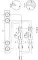
- FIG. 1 is a block diagram of an exemplary sound output device according to the embodiment.
- the sound output device includes speakers 1, 2, 3, and 4 mounted on a flat panel 10, and an output signal generator (output signal generating circuit) 100 for generating output signals for the respective speakers 1 to 4. That is, the sound output device is configured to acoustically output sound in accordance with the output signals generated based on 2-channel audio signals, namely L-channel signals (L signals) and R-channel signals (R signals), from four speakers.
- L signals L-channel signals
- R signals R-channel signals
- the speakers 1 and 2 are placed on the left side as viewed from the position of the listener to the sound output in response to the output signals, and the speakers 3 and 4 are placed on the right side.
- the listener who is listening to the sound may be positioned approximately between the speaker 2 and speaker 3.
- the speakers 1 and 4 are placed outside from the position of the listener, while the speakers 2 and 3 are placed inside. In other words, from the position of the listener, the speaker 1, speaker 2, speaker 3 and speaker 4 are placed in this order from left to right.
- the speaker 1 is an example of the first output device
- the speaker 2 is an example of the second output device
- the speaker 3 is an example of the third output device
- the speaker 4 is an example of the fourth output device.
- the speakers 1 to 4 are driven by power amplifiers 5 to 8, respectively, to output the sound.
- the L signal is split into an outer L signal and an inner L signal, which are input to the output signal generator 100.
- the R signal is split into an outer R signal and an inner R signal, which are input to the output signal generator 100.
- the outer L signal and outer R signal are respectively adjusted to a certain level by a pre-amplifier 40, and then are input to the outer balancing circuit 20 of the output signal generator 100.
- the inner L signal and inner R signal are respectively adjusted to a certain level by a pre-amplifier 50, and then are input to the inner balancing circuit 30.
- the outer balancing circuit 20 generates output signals for the outer speakers 1 and 4 from the adjusted outer L signal and outer R signal.
- the output signals are respectively input to the power amplifiers 5 and 8, which respectively drive the speakers 1 and 4 to output a part of the sound.
- the inner balancing circuit 30 generates output signals for the inner speakers 2 and 3 from the adjusted inner L signal and inner R signal.
- the output signals are respectively input to the power amplifiers 6 and 7, which respectively drive the speakers 2 and 3 to output a part of the sound.
- FIG. 2 is a diagram illustrating an example of an outer balancing circuit 20.
- the outer balancing circuit 20 includes inverting amplifiers 21 and 23 (Xvol_outside) and adders 22 and 24.
- the inverting amplifiers 21 and 23 respectively perform an inverting amplification on an input signal to a desired level and send the signal to the adders 22 and 24.
- signals of mutually opposite phases are input to the adders 22 and 24, as a result which the adders 22 and 24 serve as subtractors.
- FIG. 3 is a diagram illustrating an example of an inner balancing circuit 30.
- the inner balancing circuit 30 includes in-phase amplifiers 31 and 33 (Xvol_inside), and adders 32 and 34.
- the in-phase amplifiers 31 and 33 perform a positive-phase amplification on the input signal to a desired level and send the signal to the adders 32 and 34.
- in-phase signals are input to the adders 32 and 34, as a result of which the adders 32 and 34 serve as adders.
- the outer R signal is amplified by the inverting amplifier 21, and is mixed by the adder 22 with the outer L signal, which has an opposite phase.
- the first output signal is generated for the speaker 1.
- the outer L signal and the outer R signal can be added (mixed) together based on the first ratio to obtain the first output signal. That is, the inverting amplifier 21 and adder 22 serve as a first ratio setting block for setting the first ratio.
- the inner R signal is adjusted by an in-phase amplifier 31, and is mixed by the adder 32 with the inner L signal, which is in phase with the inner R signal.
- the second output signal is generated for the speaker 2.
- the inner L signal is adjusted by an in-phase amplifier 33, and is mixed by the adder 34 with the inner R signal, which is in phase with the inner L signal.
- the third output signal is generated for the speaker 3.
- the in-phase amplifier 33 and adder 34 serve as a third ratio setting block for setting the third ratio.
- the outer L signal is adjusted by the inverting amplifier 23, and is mixed by the adder 24 with the outer R signal, which has an opposite phase.
- the fourth output signal is generated for the speaker 4.
- Equation (3) and (4) under a condition of m>s, the parameters for multiplying R and L are positive numbers. This corresponds to FIG. 3 , where the L signal and R signal are added to the original signals.
- equations (5) and (6) are obtained.
- L L + R m ⁇ s / m + s ⁇ m + s / 2
- R R + L m ⁇ s / m + s ⁇ m + s / 2
- (m+s)/2 represents the value of the gain of the signal.
- the power amplifiers 5 to 8 are provided to amplify the signals, and therefore the signal amplification or attenuation does not need to be performed here.
- the component (m-s)/2 in equations (7) and (8) respectively corresponds to the gain of Xvol_outside in FIG. 2 and the gain of Xvol_inside in FIG. 3 .
- the condition of m>s corresponds to Xvol_inside in FIG. 3
- m ⁇ s corresponds to Xvol_outside in FIG. 2 .
- Xvol_outside is an inverting amplifier, whose gain is -(m-s)/2.
- the gains of the left and right amplifiers need to be equalized so as to maintain the left/right volume balance.
- the amplifier 21 and the amplifier 23 have the same gain
- the amplifier 31 and the amplifier 33 have the same gain.
- the gain of Xvol_inside may take a value different from that of the gain of Xvol_outside. That is, the inner signal and outer signal may take different values, m and s, respectively.
- FIG. 4 is a diagram illustrating an example of a sound setup.
- the setup of FIG. 4 realizes original 2-channel stereo localization.
- parameters m and s are set to the same percentage.
- FIG. 5 is a diagram illustrating another example of a sound setup.
- a negative value may be set to the inverting amplifiers 21 and 23 (Xvol_outside) of the outer balancing circuit 20, and the L and R signals that have passed through the outer balancing circuit 20 are reproduced from the outer speakers 1 and 4. This corresponds to mutual offsetting of the L signal and R signal at a certain percentage. If the cohesiveness of the sound should be emphasized, a positive value is set to the in-phase amplifiers 31 and 33 (Xvol_inside) of the inner balancing circuit 30, and the L and R signals that have passed through the inner balancing circuit 30 are reproduced from the inner speakers 2 and 3. This corresponds to an addition of the L signal and R signal in a certain proportion.
- the value s is increased and the value m is decreased (or unchanged) so as to enhance the Side component.
- the value m is increased and the value s is decreased (or unchanged) to enhance the Mid component. It is possible to directly manipulate the value of Xvol, regardless of the values m and s, while checking the sound quality in consideration of the acoustic characteristics of the place where the sound output device is installed.
- the proportion (first proportion) of the coefficients of the L signal and R signal in the outer signal L1 that are to be added together is 1:b. That is, the ratio of the coefficient of the R signal to that of the L signal is b (first ratio).
- the proportion (second proportion) of the coefficients of the L signal and R signal in the inner signal L2 that are to be added together is 1:a. That is, the ratio of the coefficient of the R signal to that of the L signal is a (second ratio).
- the proportion (third proportion) of the coefficients of the L signal and R signal in the inner signal R3 that are to be added together is a:1. That is, the ratio of the coefficient of the R signal to that of the L signal is 1/a (third ratio).
- the proportion (fourth proportion) of the coefficients of the L signal and R signal in the outer signal R4 that are to be added together is b :1. That is, the ratio of the coefficient of the R signal to that of the L signal is 1/b (fourth ratio).
- the first ratio representing the ratio of the coefficient of the R signal to that of the L signal is reciprocal to the fourth ratio.
- the second ratio representing the ratio of the coefficient of the R signal to that of the L signal is reciprocal to the third ratio.
- (m+s)/2 1 is established.
- a represents a positive number
- b is a negative number.
- a and b may each take a value between -1 and 1.
- the inner signal becomes a differential signal, or in other words, it becomes a Side component.
- the outer signal becomes a Mid component. Such effects may be intentionally created.
- the first proportion corresponding to the first ratio and the second proportion corresponding to the second ratio are respectively one proportion in the range of 1:-1 to 1:1.
- the first proportion represents a proportion of the coefficient of the L signal to the coefficient of the R signal.
- the second proportion also represents a proportion of the coefficient of the L signal to the coefficient of the R signal.
- the third proportion which corresponds to the third ratio
- the fourth proportion which corresponds to the fourth ratio
- the third proportion represents a proportion of the coefficient of the L signal to the coefficient of the R signal.
- the fourth proportion represents a proportion of the coefficient of the L signal to the coefficient of the R signal.
- FIG. 6 is a block diagram illustrating a comparative example of a conventional speaker system.
- the parameters m and s cannot be independently set, nor can they be variably set.
- the parameters m and s can be adjusted so that the sound with a broader sense of spaciousness can be realized in comparison to sound easily reproduced by the same two-channel stereo signals. Moreover, phase interference can be mitigated.
- FIG. 7 is an external view of an exemplary electronic musical instrument 200 provided with a sound output device.
- the electronic musical instrument 200 may be a digital piano having a keyboard and speakers for reproducing and outputting electronically generated sound.
- the electronic musical instrument 200 may be a computer in which a processor and a storage are incorporated.
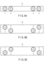
- FIG. 8A is a diagram illustrating an exemplary arrangement of speakers in an electronic musical instrument 200.
- the back view of the electronic musical instrument 200 as viewed from its back surface is depicted in FIG. 8A , with speakers 1 to 4 mounted on a back panel.
- a pair of speakers may be closely arranged on the left and on the right laterally along the direction of keys of the keyboard.
- the speakers 1 to 4 are arranged on the upper panel.
- the upper panel provides a larger area than the back panel.
- the outer speakers 1 and 4 may be arranged farther away from the listener (player), while the inner speakers 2 and 3 may be displaced so as to be closer to the listener.
- the outer speakers 1 and 4 may be arranged closer to the listener, while the inner speakers 2 and 3 may be displaced so as to be farther away from the listener.
- FIG. 9A is a diagram illustrating another exemplary arrangement of speakers in the electronic musical instrument 200.
- the cross section of the electronic musical instrument 200 as viewed from its lateral side is depicted in FIG. 9A .
- FIG. 9A the arrangement of FIG. 8A is indicated, while in FIG. 9B , the arrangement of FIG. 8B is indicated.
- the structures depicted in FIGS. 9C and 9D include a sound hole 60 in the panel 10 so as to create bass reflex effects.
- the speakers may be arranged by providing an opening that faces outwardly with respect to the digital piano body.
- the speakers may be arranged by providing an opening that faces inwardly with respect to the digital piano body so that the reproduced sound will be audible through the sound hole 60.
- signals of desired levels are generated for two inner channels and two outer channels from a 2-channel L/R stereo input signal. And from these generated signals, a differential signal or a sum signal of a desired level is generated by the output signal generator 100.
- the sound output device reproduces the sound generated in accordance with an L stereo signal and an R stereo signal are respectively split to the left and right signals, through four speakers including a pair of speakers closely arranged on the left and a pair of speakers closely arranged on the right. More specifically, the sound output device outputs sound based on an L signal with the Side component adjusted according to a signal component which a signal obtained by multiplying the R signal by arbitrary percentage is subtracted from the L signal, through the outer speaker 1.
- the sound output device outputs sound based on an R signal with the Side component adjusted according to a signal component which a signal obtained by multiplying the L signal by arbitrary percentage is subtracted from the R signal, through the outer speaker 4. Furthermore, the sound output device outputs sound based on n L signal with the Mid component adjusted according to a signal component which a signal obtained by multiplying the R signal by arbitrary percentage is added to the L signal, through the inner speaker 2. The sound output device outputs sound based on an R signal with the Mid component adjusted according to a signal component which a signal obtained by multiplying the L signal by arbitrary percentage is added to the R signal, through the inner speaker 3. In this manner, the spaciousness and cohesiveness of the stereo sound can be controlled, and the phase interference can be mitigated.
- a Mid signal and a Side signal can be generated from the L signal and R signal so that Mid balance and Side balance can be adjusted on the inner side and on the outer side.
- a sense of spaciousness and a sense of cohesiveness can be controlled.
- the acoustic effects can be enhanced by adjusting the Mid volume for the inner signal and the Side volume for the outer signal.
- auditory comfortability such as a sense of spaciousness and a sense of cohesiveness can be freely controlled, and the phase interference can be mitigated.
- the present embodiment offers a sound output device, sound output method, and storage medium, which can enhance the degree of freedom for controlling the listening experience.
- the present invention is not limited to the above embodiment.
- the adder 22 adds an inverted signal obtained by inverting the outer R signal to the outer L signal
- the adder 24 adds an inverted signal obtained by inverting the outer L signal to the outer R signal.
- the adder 22 substracts the outer R signal from the outer L signal
- the adder 24 substracts the outer L signal from the outer R signal. This is to generate a differential signal of the outer L signal and outer R signal.
- the adder 32 adds the inner R signal to the inner L signal
- the adder 34 adds the inner L signal to the inner R signal.
- the subtraction is not limited to the outer signals, and the addition is not limited to the inner signals.
- the subtraction of the outer signals and addition of the inner signals may be preferable to produce natural listening experience effects; however, for eccentric listening experience effects, the L signal and R signal may be submitted to the subtraction, or to the addition, on both the outer and inner sides.
- FIGS. 1 to 3 may be realized by software digital calculation processing.
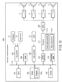
- FIG. 10 is a functional block diagram of the exemplary electronic musical instrument 200 illustrated in FIG. 7 .
- the electronic musical instrument 200 includes, in addition to the speakers 1 to 4 and power amplifiers 5 to 8, a keyboard 11, an input block 12, a liquid crystal display (LCD) 13, a central processing unit (CPU) 101, a read-only memory (ROM) 102, a random-access memory (RAM) 103, a storage 104, a key scanner 105, an LCD controller 106, a sound generator 107, a digital-to-analog converter (DAC) 108, a communication block 110, a processor 111, and a bus 112.
- the CPU 101 controls the overall operation of the electronic musical instrument 200.
- the CPU 101 may expand (read out) a program 102a stored in the ROM 102 or storage 104 into the RAM 103. By executing the program expanded in the RAM 103, the CPU 101 realizes various functions of the electronic musical instrument 200.
- the ROM 102 is a read-only storage specifically designed to store data in a nonvolatile manner.
- the ROM 102 may store a system control program for controlling the electronic musical instrument 200 and sound waveform data for generating musical tones.
- the RAM 103 is a storage utilized as a work area of the CPU 101.
- the RAM 103 may store data necessary to execute a program stored in the ROM 102 or storage 104.
- the RAM 103 also temporarily stores data such as sound waveform data.
- the storage 104 stores data in a nonvolatile and readable/rewritable manner.
- the storage 104 may store recorded data.
- the storage 104 may be externally coupled to the electronic musical instrument 200.
- the key scanner 105 is an integrated circuit (IC) that can detect the manipulation state of a manipulation terminal.
- the key scanner 105 is coupled to the keyboard 11 and input block 12.
- the key scanner 105 constantly monitors the key strike/release state (operation state) of the keyboard 11, and the operation state of the input block 12. Then, the key scanner 105 informs the CPU 101 of the operation states of the keyboard 11 and the input block 12.
- the LCD controller 106 is an IC coupled to the LCD 13 to control the display mode of the LCD 13.
- the LCD controller 106 displays various kinds of information on the LCD 13 under the control performed by the CPU 101.
- the LCD controller 106 is replaceable in accordance with the specifications of the display mounted on the electronic musical instrument 200.
- the sound generator 107 may be a General MIDI (GM) sound generator in conformity with the GM standard.
- the sound generator 107 may have the ability to simultaneously produce up to 256 voices at maximum, allowing for the use of multiple tones.
- the sound generator 107 may read sound waveform data from the RAM 103 under the control of the CPU 101, and input the read-out sound waveform data into the processor 111. This sound waveform data includes two channels for L signals and R signals.
- the processor 111 may be a digital signal processor (DSP) that is a computational device for processing the sound waveform data in a digital field. Based on the sound waveform data, the processor 111 generates a first output signal for the speaker 1, a second output signal for the speaker 2, a third output signal for the speaker 3, and a fourth output signal for the speaker 4, and inputs them to the DAC 108.
- DSP digital signal processor
- the DAC 108 performs digital-to-analog conversion on the first to fourth output signals and inputs the resultant signals respectively to the power amplifiers 5 to 8.
- the power amplifiers 5 to 8 amplify analog signals from the DAC 108, and drive the speakers 1 to 4 to output the sound.
- the communication block 110 is used for a connection with a tablet computer or a smartphone.
- the communication block 110 includes a BLE-MIDI communication block.
- the communication block 110 informs the CPU 101 of a signal received from a terminal device, and outputs to the terminal device a signal output from the key scanner 105 and the like.
- the bus 112 is a data transmission path used for communications among the components of the electronic musical instrument 200.
- the CPU 101, ROM 102, RAM 103, storage 104, key scanner 105, LCD controller 106, sound generator 107, and communication block 110 are coupled.
- Various devices such as pedals used for playing may be coupled to the bus 112.
- the electronic musical instrument 200 may be operated based on the manipulation of the external terminal.
- the processor 111 includes an output signal generator 111a and a ratio setting block 111b.
- the output signal generator 111a generates an outer L signal and an inner L signal from the L signal data of the sound waveform data received from the sound generator 107, and an outer R signal and an inner R signal from the R signal data.
- the output signal generator 111a adds the outer L signal and outer R signal in accordance with the first ratio to generate the first output signal.
- the output signal generator 111a further adds the inner L signal and inner R signal in accordance with the second ratio to generate the second output signal.
- the output signal generator 111a further adds the inner L signal and inner R signal in accordance with the third ratio to generate the third output signal.
- the output signal generator 111a adds the outer L signal and outer R signal in accordance with the fourth ratio to generate the fourth output signal.
- the ratio setting block 111b sets the first ratio, second ratio, third ratio, and fourth ratio.
- the program 102a includes commands for causing the computer to function as the output signal generator 111a.
- the program 102a includes a command for causing the processor 111 to generate the first output signal by adding the outer L signal and outer R signal based on the first ratio, a command for causing it to generate the second output signal by adding the inner L signal and inner R signal based on the second ratio, a command for causing it to generate a third output signal by adding the inner L signal and inner R signal based on the third ratio, and a command for causing it to generate a fourth output signal by adding the outer L signal and outer R signal based on the fourth ratio.
- the program 102a further includes a command for causing the computer to function as the ratio setting block 111b.
- the sound output device may be realized by computational processing performed by a processor.
- This embodiment is compatible with a configuration in which an L signal and an R signal are provided as digital data.
Landscapes
- Engineering & Computer Science (AREA)
- Physics & Mathematics (AREA)
- Acoustics & Sound (AREA)
- Signal Processing (AREA)
- Multimedia (AREA)
- Stereophonic System (AREA)
- Circuit For Audible Band Transducer (AREA)
- Electrophonic Musical Instruments (AREA)
Abstract
A sound output device includes an output signal generator(111a). The output signal generator(111a) generates a first output signal for sound to be output from a first output device by mixing a left-channel signal and a right-channel signal based on a first ratio. The output signal generator(111a) generates a second output signal for sound to be output from a second output device by mixing the left-channel signal and the right-channel signal based on a second ratio. The output signal generator(1l1a) generates a third output signal for sound to be output from a third output device by mixing the left-channel signal and the right-channel signal based on a third ratio. And the output signal generator(111a) generates a fourth output signal for sound to be output from a first output device by mixing the left-channel signal and the right-channel signal based on a fourth ratio.
Description
- The present invention relates generally to a sound output device, a sound output method, and a program.
- Sound outputting devices using loudspeakers and amplifiers have been widely known, such as home audio systems, car audio systems, electronic musical instruments, and public address (PA) systems. Among these, monophonic systems are now less common, while systems that deal with stereo signals for the left (L) channel and right (R) channels are commonly used.
- For instance, as disclosed in Jpn. Pat. Appln. KOKAI Publication No.
H6-289859 - With the conventional technique, the lateral spread of sound can only be controlled by adjusting the volume. If this is overdone, signals of the same type may be reproduced and output from adjacent speakers at different levels, which may intensify the phase interference. Excessive phase interference creates an unnatural listening experience, making it difficult to create a comfortable sound space. If the crossover frequency is adjusted to mitigate the phase interference, the desired sense of spaciousness cannot be attained. A technique for enhancing the degrees of freedom in controlling the environment for listening to the reproduced sound and feel of the reproduced sound has been demanded.
- One of the advantages in the invention is that a sound output device comprising an output signal generator, the output signal generator being configured to generate a first output signal for sound to be output from a first output device by mixing a left-channel signal and a right-channel signal based on a first ratio, generate a second output signal for sound to be output from a second output device by mixing the left-channel signal and the right-channel signal based on a second ratio, generate a third output signal for sound to be output from a third output device by mixing the left-channel signal and the right-channel signal based on a third ratio, and generate a fourth output signal for sound to be output from a fourth output device by mixing the left-channel signal and the right-channel signal based on a fourth ratio.
-
-
FIG. 1 is a block diagram illustrating an example of a speaker system according to the present embodiment. -
FIG. 2 is a diagram illustrating an example of anouter balancing circuit 20. -
FIG. 3 is a diagram illustrating an example of aninner balancing circuit 30. -
FIG. 4 is a diagram illustrating an example of sound setup. -
FIG. 5 is a diagram illustrating another example of sound setup. -
FIG. 6 is a block diagram illustrating a comparative example of a conventional speaker system. -
FIG. 7 is an external view of an exemplary electronic musical instrument provided with a sound output device. -
FIG. 8A is a diagram illustrating an exemplary arrangement of speakers in the electronic musical instrument. -
FIG. 8B is a diagram illustrating another exemplary arrangement of speakers in the electronic musical instrument. -
FIG. 8C is a diagram illustrating another exemplary arrangement of speakers in the electronic musical instrument. -
FIG. 9A is a diagram illustrating another exemplary arrangement of speakers in the electronic musical instrument. -
FIG. 9B is a diagram illustrating another exemplary arrangement of speakers in the electronic musical instrument. -
FIG. 9C is a diagram illustrating another exemplary arrangement of speakers in the electronic musical instrument. -
FIG. 9D is a diagram illustrating another exemplary arrangement of speakers in the electronic musical instrument. -
FIG. 10 is a functional block diagram of the exemplary electronic musical instrument illustrated inFIG. 7 . - An embodiment of the present invention will be described below.
-
FIG. 1 is a block diagram of an exemplary sound output device according to the embodiment. The sound output device includesspeakers flat panel 10, and an output signal generator (output signal generating circuit) 100 for generating output signals for therespective speakers 1 to 4. That is, the sound output device is configured to acoustically output sound in accordance with the output signals generated based on 2-channel audio signals, namely L-channel signals (L signals) and R-channel signals (R signals), from four speakers. - According to the present embodiment, the
speakers speakers speaker 2 andspeaker 3. Thespeakers speakers speaker 1,speaker 2,speaker 3 andspeaker 4 are placed in this order from left to right. Thespeaker 1 is an example of the first output device, thespeaker 2 is an example of the second output device, thespeaker 3 is an example of the third output device, and thespeaker 4 is an example of the fourth output device. Thespeakers 1 to 4 are driven bypower amplifiers 5 to 8, respectively, to output the sound. - In
FIG. 1 , the L signal is split into an outer L signal and an inner L signal, which are input to theoutput signal generator 100. Similarly, the R signal is split into an outer R signal and an inner R signal, which are input to theoutput signal generator 100. - The outer L signal and outer R signal are respectively adjusted to a certain level by a pre-amplifier 40, and then are input to the
outer balancing circuit 20 of theoutput signal generator 100. Similarly, the inner L signal and inner R signal are respectively adjusted to a certain level by a pre-amplifier 50, and then are input to theinner balancing circuit 30. - The
outer balancing circuit 20 generates output signals for theouter speakers power amplifiers speakers - The
inner balancing circuit 30 generates output signals for theinner speakers power amplifiers speakers -
FIG. 2 is a diagram illustrating an example of anouter balancing circuit 20. Theouter balancing circuit 20 includes invertingamplifiers 21 and 23 (Xvol_outside) andadders amplifiers adders adders adders -
FIG. 3 is a diagram illustrating an example of aninner balancing circuit 30. Theinner balancing circuit 30 includes in-phase amplifiers 31 and 33 (Xvol_inside), andadders phase amplifiers adders adders adders - In
FIG. 2 , the outer R signal is amplified by the invertingamplifier 21, and is mixed by theadder 22 with the outer L signal, which has an opposite phase. As a result, the first output signal is generated for thespeaker 1. By setting the gain of the invertingamplifier 21 to any desired value, the outer L signal and the outer R signal can be added (mixed) together based on the first ratio to obtain the first output signal. That is, the invertingamplifier 21 andadder 22 serve as a first ratio setting block for setting the first ratio. - In
FIG. 3 , the inner R signal is adjusted by an in-phase amplifier 31, and is mixed by theadder 32 with the inner L signal, which is in phase with the inner R signal. As a result, the second output signal is generated for thespeaker 2. By setting the gain of the in-phase amplifier 31 to any desired value, the inner L signal and the inner R signal can be added (mixed) together based on the second ratio to obtain the second output signal. That is, the in-phase amplifier 31 andadder 32 serve as a second ratio setting block for setting the second ratio. - In
FIG. 3 , the inner L signal is adjusted by an in-phase amplifier 33, and is mixed by theadder 34 with the inner R signal, which is in phase with the inner L signal. As a result, the third output signal is generated for thespeaker 3. By setting the gain of the in-phase amplifier 33 to any desired value, the inner L signal and the inner R signal can be added (mixed) together based on the third ratio to obtain the third output signal. That is, the in-phase amplifier 33 andadder 34 serve as a third ratio setting block for setting the third ratio. - The description returns to
FIG. 2 . InFIG. 2 , the outer L signal is adjusted by the invertingamplifier 23, and is mixed by theadder 24 with the outer R signal, which has an opposite phase. As a result, the fourth output signal is generated for thespeaker 4. By setting the gain of the invertingamplifier 23 to any desired value, the outer L signal and the outer R signal can be added (mixed) together based on the fourth ratio to obtain the fourth output signal. That is, the invertingamplifier 23 andadder 24 serve as a fourth ratio setting block for setting the fourth ratio. - Next, the advantageous effects produced by the above configuration will be described.
- In the sound processing known as mid/side processing, signals of two channels, L and R, are processed by splitting them into middle components (Mid) and side components (Side). This processing is adopted in the present embodiment. If it is assumed that:


- Assuming that m represents the component adjustment parameter of the Mid component and s represents the component adjustment parameter of the Side component, L and R can be expressed as follows:
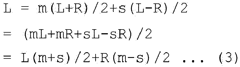

- In equations (3) and (4), under a condition of m>s, the parameters for multiplying R and L are positive numbers. This corresponds to
FIG. 3 , where the L signal and R signal are added to the original signals. - On the other hand, under a condition of m<s in equations (3) and (4), the parameters for multiplying R and L are negative numbers. This corresponds to
FIG. 2 , where the L signal and R signal are subtracted from the original signals. - Under a condition of m = s = 1, it holds that L = L, and R = R. Thus, the localization of the original sounds in two-channel stereo can be produced.
- By further rearranging the equations (3) and (4), equations (5) and (6) are obtained.


- In equations (5) and (6), (m+s)/2 represents the value of the gain of the signal. In the present embodiment, the
power amplifiers 5 to 8 are provided to amplify the signals, and therefore the signal amplification or attenuation does not need to be performed here. In other words, (m+s)/2 = 1 can be established, and therefore it can be considered that m+s = 2. Then, the equations (5) and (6) are further rearranged as follows:

- The component (m-s)/2 in equations (7) and (8) respectively corresponds to the gain of Xvol_outside in
FIG. 2 and the gain of Xvol_inside inFIG. 3 . As mentioned above, the condition of m>s corresponds to Xvol_inside inFIG. 3 , while the case where m<s corresponds to Xvol_outside inFIG. 2 . According to the present embodiment, Xvol_outside is an inverting amplifier, whose gain is -(m-s)/2. - Here, in order to prevent the left/right sound localization from changing from the localization of the original stereo signals, the gains of the left and right amplifiers need to be equalized so as to maintain the left/right volume balance. In other words, the
amplifier 21 and theamplifier 23 have the same gain, and theamplifier 31 and theamplifier 33 have the same gain. On the other hand, the gain of Xvol_inside may take a value different from that of the gain of Xvol_outside. That is, the inner signal and outer signal may take different values, m and s, respectively. -
FIG. 4 is a diagram illustrating an example of a sound setup. The setup ofFIG. 4 realizes original 2-channel stereo localization. In theouter balancing circuit 20 andinner balancing circuit 30 ofFIG. 4 , parameters m and s are set to the same percentage. -
FIG. 5 is a diagram illustrating another example of a sound setup. For instance, in order to enhance the sense of spaciousness of the reproduced sound from theouter speakers inner speakers outer balancing circuit 20, and m:s = 60:40 may be set in theinner balancing circuit 30. - In
FIG. 5 , in order to emphasize the sense of spaciousness of sound, a negative value may be set to the invertingamplifiers 21 and 23 (Xvol_outside) of theouter balancing circuit 20, and the L and R signals that have passed through theouter balancing circuit 20 are reproduced from theouter speakers phase amplifiers 31 and 33 (Xvol_inside) of theinner balancing circuit 30, and the L and R signals that have passed through theinner balancing circuit 30 are reproduced from theinner speakers - That is, to enhance the left/right lateral sound width, the value s is increased and the value m is decreased (or unchanged) so as to enhance the Side component. In contrast, to enhance the sound cohesiveness toward the center, the value m is increased and the value s is decreased (or unchanged) to enhance the Mid component. It is possible to directly manipulate the value of Xvol, regardless of the values m and s, while checking the sound quality in consideration of the acoustic characteristics of the place where the sound output device is installed.
- With m = 2 and s = 0, the monaural center localization (max Mid) can be realized. With m = 0 and s = 2, there is no L/R correlation (max Side), and therefore an L differential signal and an R differential signal can be obtained.
- In equations (7) and (8), if a (where a is a positive number) represents (m-s)/2 corresponding to the gain of Xvol_inside and b (where b is a negative number) represents (m-s)/2 corresponding to the gain of the Xvol_outside, the output signal L1 for the
speaker 1, the output signal L2 for thespeaker 2, the output signal R3 for thespeaker 3, and the output signal R4 for thespeaker 4 are expressed by the following equations (9) to (12).


- From equation (9), the proportion (first proportion) of the coefficients of the L signal and R signal in the outer signal L1 that are to be added together is 1:b. That is, the ratio of the coefficient of the R signal to that of the L signal is b (first ratio).
- From equation (10), the proportion (second proportion) of the coefficients of the L signal and R signal in the inner signal L2 that are to be added together is 1:a. That is, the ratio of the coefficient of the R signal to that of the L signal is a (second ratio).
- From equation (11), the proportion (third proportion) of the coefficients of the L signal and R signal in the inner signal R3 that are to be added together is a:1. That is, the ratio of the coefficient of the R signal to that of the L signal is 1/a (third ratio).
- From equation (12), the proportion (fourth proportion) of the coefficients of the L signal and R signal in the outer signal R4 that are to be added together is b:1. That is, the ratio of the coefficient of the R signal to that of the L signal is 1/b (fourth ratio).
- As seen from the above, the first ratio representing the ratio of the coefficient of the R signal to that of the L signal is reciprocal to the fourth ratio. Further, the second ratio representing the ratio of the coefficient of the R signal to that of the L signal is reciprocal to the third ratio.
- According to the present embodiment, (m+s)/2 = 1 is established. This means that -2 ≤ m-s ≤ 2, or in other words, -1 ≤ (m-s)/2 ≤ 1. In the above description, a represents a positive number, and b is a negative number. However, a and b may each take a value between -1 and 1.
- If a < 0 is satisfied for the
inner speakers - In general, the first proportion corresponding to the first ratio and the second proportion corresponding to the second ratio are respectively one proportion in the range of 1:-1 to 1:1. The first proportion represents a proportion of the coefficient of the L signal to the coefficient of the R signal. The second proportion also represents a proportion of the coefficient of the L signal to the coefficient of the R signal.
- Furthermore, the third proportion, which corresponds to the third ratio, and the fourth proportion, which corresponds to the fourth ratio, are respectively one proportion in the range of 1:-1 to 1:1. The third proportion represents a proportion of the coefficient of the L signal to the coefficient of the R signal. The fourth proportion represents a proportion of the coefficient of the L signal to the coefficient of the R signal.
- In order to obtain the effect of controlling the spread of sound, it is preferable that a and b should be controlled to satisfy 0 ≤ a ≤ 1 and -1 ≤ b ≤ 0. That is, the inner signal is controlled to satisfy m ≥ s, while the outer signal is controlled to satisfy m ≤ s, where m+s = 2.
- In general, a proportion does not include a component 0. According to the present embodiment, however, a proportion may allow for 1:0 and 0:1. This corresponds to the case of a = 0 or b = 0, which indicates that the L signal and R signal are output as-is.
-
FIG. 6 is a block diagram illustrating a comparative example of a conventional speaker system. In this system, the parameters m and s cannot be independently set, nor can they be variably set. - In contrast, according to the present embodiment, the parameters m and s can be adjusted so that the sound with a broader sense of spaciousness can be realized in comparison to sound easily reproduced by the same two-channel stereo signals. Moreover, phase interference can be mitigated.
- The modification examples of the present embodiment will be described below.
-
FIG. 7 is an external view of an exemplary electronicmusical instrument 200 provided with a sound output device. The electronicmusical instrument 200 may be a digital piano having a keyboard and speakers for reproducing and outputting electronically generated sound. The electronicmusical instrument 200 may be a computer in which a processor and a storage are incorporated. -
FIG. 8A is a diagram illustrating an exemplary arrangement of speakers in an electronicmusical instrument 200. The back view of the electronicmusical instrument 200 as viewed from its back surface is depicted inFIG. 8A , withspeakers 1 to 4 mounted on a back panel. As illustrated in this drawing, a pair of speakers may be closely arranged on the left and on the right laterally along the direction of keys of the keyboard. - In
FIG. 8B , thespeakers 1 to 4 are arranged on the upper panel. In most structures, the upper panel provides a larger area than the back panel. As depicted inFIG. 8B , theouter speakers inner speakers FIG. 8C , theouter speakers inner speakers -
FIG. 9A is a diagram illustrating another exemplary arrangement of speakers in the electronicmusical instrument 200. The cross section of the electronicmusical instrument 200 as viewed from its lateral side is depicted inFIG. 9A . InFIG. 9A , the arrangement ofFIG. 8A is indicated, while inFIG. 9B , the arrangement ofFIG. 8B is indicated. - The structures depicted in
FIGS. 9C and 9D include asound hole 60 in thepanel 10 so as to create bass reflex effects. As shown inFIG. 9C , the speakers may be arranged by providing an opening that faces outwardly with respect to the digital piano body. Alternatively, as shown inFIG. 9D , the speakers may be arranged by providing an opening that faces inwardly with respect to the digital piano body so that the reproduced sound will be audible through thesound hole 60. - As described above, according to the present embodiment, signals of desired levels are generated for two inner channels and two outer channels from a 2-channel L/R stereo input signal. And from these generated signals, a differential signal or a sum signal of a desired level is generated by the
output signal generator 100. In other words, the sound output device reproduces the sound generated in accordance with an L stereo signal and an R stereo signal are respectively split to the left and right signals, through four speakers including a pair of speakers closely arranged on the left and a pair of speakers closely arranged on the right. More specifically, the sound output device outputs sound based on an L signal with the Side component adjusted according to a signal component which a signal obtained by multiplying the R signal by arbitrary percentage is subtracted from the L signal, through theouter speaker 1. Furthermore, the sound output device outputs sound based on an R signal with the Side component adjusted according to a signal component which a signal obtained by multiplying the L signal by arbitrary percentage is subtracted from the R signal, through theouter speaker 4. Furthermore,the sound output device outputs sound based on n L signal with the Mid component adjusted according to a signal component which a signal obtained by multiplying the R signal by arbitrary percentage is added to the L signal, through theinner speaker 2. The sound output device outputs sound based on an R signal with the Mid component adjusted according to a signal component which a signal obtained by multiplying the L signal by arbitrary percentage is added to the R signal, through theinner speaker 3. In this manner, the spaciousness and cohesiveness of the stereo sound can be controlled, and the phase interference can be mitigated. - Moreover, according to the present embodiment, a Mid signal and a Side signal can be generated from the L signal and R signal so that Mid balance and Side balance can be adjusted on the inner side and on the outer side. In this manner, a sense of spaciousness and a sense of cohesiveness can be controlled. In particular, the acoustic effects can be enhanced by adjusting the Mid volume for the inner signal and the Side volume for the outer signal. Furthermore, according to the present embodiment, auditory comfortability such as a sense of spaciousness and a sense of cohesiveness can be freely controlled, and the phase interference can be mitigated.
- In this manner, the present embodiment offers a sound output device, sound output method, and storage medium, which can enhance the degree of freedom for controlling the listening experience.
- The present invention, however, is not limited to the above embodiment. For instance, in the configuration of
FIG. 2 , theadder 22 adds an inverted signal obtained by inverting the outer R signal to the outer L signal, and theadder 24 adds an inverted signal obtained by inverting the outer L signal to the outer R signal. In other words, theadder 22 substracts the outer R signal from the outer L signal, and theadder 24 substracts the outer L signal from the outer R signal. This is to generate a differential signal of the outer L signal and outer R signal. Furthermore, in the configuration ofFIG. 3 , theadder 32 adds the inner R signal to the inner L signal, and theadder 34 adds the inner L signal to the inner R signal. This is to generate a sum signal of the inner L signal and inner R signal. It should be noted, however, that the subtraction is not limited to the outer signals, and the addition is not limited to the inner signals. The subtraction of the outer signals and addition of the inner signals may be preferable to produce natural listening experience effects; however, for eccentric listening experience effects, the L signal and R signal may be submitted to the subtraction, or to the addition, on both the outer and inner sides. - The configurations of
FIGS. 1 to 3 may be realized by software digital calculation processing. -
FIG. 10 is a functional block diagram of the exemplary electronicmusical instrument 200 illustrated inFIG. 7 . The electronicmusical instrument 200 includes, in addition to thespeakers 1 to 4 andpower amplifiers 5 to 8, akeyboard 11, aninput block 12, a liquid crystal display (LCD) 13, a central processing unit (CPU) 101, a read-only memory (ROM) 102, a random-access memory (RAM) 103, astorage 104, akey scanner 105, anLCD controller 106, asound generator 107, a digital-to-analog converter (DAC) 108, acommunication block 110, aprocessor 111, and abus 112. - The
CPU 101 controls the overall operation of the electronicmusical instrument 200. TheCPU 101 may expand (read out) aprogram 102a stored in theROM 102 orstorage 104 into theRAM 103. By executing the program expanded in theRAM 103, theCPU 101 realizes various functions of the electronicmusical instrument 200. - The
ROM 102 is a read-only storage specifically designed to store data in a nonvolatile manner. TheROM 102 may store a system control program for controlling the electronicmusical instrument 200 and sound waveform data for generating musical tones. - The
RAM 103 is a storage utilized as a work area of theCPU 101. For instance, theRAM 103 may store data necessary to execute a program stored in theROM 102 orstorage 104. TheRAM 103 also temporarily stores data such as sound waveform data. - The
storage 104 stores data in a nonvolatile and readable/rewritable manner. Thestorage 104 may store recorded data. Thestorage 104 may be externally coupled to the electronicmusical instrument 200. - The
key scanner 105 is an integrated circuit (IC) that can detect the manipulation state of a manipulation terminal. Thekey scanner 105 is coupled to thekeyboard 11 andinput block 12. Thekey scanner 105 constantly monitors the key strike/release state (operation state) of thekeyboard 11, and the operation state of theinput block 12. Then, thekey scanner 105 informs theCPU 101 of the operation states of thekeyboard 11 and theinput block 12. - The
LCD controller 106 is an IC coupled to theLCD 13 to control the display mode of theLCD 13. TheLCD controller 106 displays various kinds of information on theLCD 13 under the control performed by theCPU 101. TheLCD controller 106 is replaceable in accordance with the specifications of the display mounted on the electronicmusical instrument 200. - The
sound generator 107 may be a General MIDI (GM) sound generator in conformity with the GM standard. Thesound generator 107 may have the ability to simultaneously produce up to 256 voices at maximum, allowing for the use of multiple tones. Thesound generator 107 may read sound waveform data from theRAM 103 under the control of theCPU 101, and input the read-out sound waveform data into theprocessor 111. This sound waveform data includes two channels for L signals and R signals. - The
processor 111 may be a digital signal processor (DSP) that is a computational device for processing the sound waveform data in a digital field. Based on the sound waveform data, theprocessor 111 generates a first output signal for thespeaker 1, a second output signal for thespeaker 2, a third output signal for thespeaker 3, and a fourth output signal for thespeaker 4, and inputs them to theDAC 108. - The
DAC 108 performs digital-to-analog conversion on the first to fourth output signals and inputs the resultant signals respectively to thepower amplifiers 5 to 8. Thepower amplifiers 5 to 8 amplify analog signals from theDAC 108, and drive thespeakers 1 to 4 to output the sound. - The
communication block 110 is used for a connection with a tablet computer or a smartphone. Thecommunication block 110 includes a BLE-MIDI communication block. Thecommunication block 110 informs theCPU 101 of a signal received from a terminal device, and outputs to the terminal device a signal output from thekey scanner 105 and the like. - The
bus 112 is a data transmission path used for communications among the components of the electronicmusical instrument 200. To thebus 112, theCPU 101,ROM 102,RAM 103,storage 104,key scanner 105,LCD controller 106,sound generator 107, andcommunication block 110 are coupled. Various devices such as pedals used for playing may be coupled to thebus 112. With an external terminal coupled to thebus 112 in a wired or wireless manner, the electronicmusical instrument 200 may be operated based on the manipulation of the external terminal. - As the functions relating to the present embodiment, the
processor 111 includes anoutput signal generator 111a and aratio setting block 111b. - The
output signal generator 111a generates an outer L signal and an inner L signal from the L signal data of the sound waveform data received from thesound generator 107, and an outer R signal and an inner R signal from the R signal data. - Furthermore, the
output signal generator 111a adds the outer L signal and outer R signal in accordance with the first ratio to generate the first output signal. Theoutput signal generator 111a further adds the inner L signal and inner R signal in accordance with the second ratio to generate the second output signal. Theoutput signal generator 111a further adds the inner L signal and inner R signal in accordance with the third ratio to generate the third output signal. Furthermore, theoutput signal generator 111a adds the outer L signal and outer R signal in accordance with the fourth ratio to generate the fourth output signal. - The
ratio setting block 111b sets the first ratio, second ratio, third ratio, and fourth ratio. - The
program 102a includes commands for causing the computer to function as theoutput signal generator 111a. In other words, theprogram 102a includes a command for causing theprocessor 111 to generate the first output signal by adding the outer L signal and outer R signal based on the first ratio, a command for causing it to generate the second output signal by adding the inner L signal and inner R signal based on the second ratio, a command for causing it to generate a third output signal by adding the inner L signal and inner R signal based on the third ratio, and a command for causing it to generate a fourth output signal by adding the outer L signal and outer R signal based on the fourth ratio. - The
program 102a further includes a command for causing the computer to function as theratio setting block 111b. - As described above, the sound output device according to the present embodiment may be realized by computational processing performed by a processor. This embodiment is compatible with a configuration in which an L signal and an R signal are provided as digital data.
- Several embodiments of the present invention have been explained, merely as examples, and thus are not meant to restrict the scope of invention. Indeed, the embodiments may be embodied in various other forms; furthermore, various omissions, substitutions and changes may be made without departing from the spirit of the invention. The accompanying claims and their equivalents are intended to cover such forms or modifications as would fall within the scope and spirit of the invention.
Claims (17)
- A sound output device comprising an output signal generator(111a), the output signal generator(111a) being configured to:generate a first output signal for sound to be output from a first output device by mixing a left-channel signal and a right-channel signal based on a first ratio;generate a second output signal for sound to be output from a second output device by mixing the left-channel signal and the right-channel signal based on a second ratio;generate a third output signal for sound to be output from a third output device by mixing the left-channel signal and the right-channel signal based on a third ratio; andgenerate a fourth output signal for sound to be output from a fourth output device by mixing the left-channel signal and the right-channel signal based on a fourth ratio.
- The sound output device according to claim 1, wherein
the output signal generator(111a) sets the first ratio, the second ratio, the third ratio, and the fourth ratio. - The sound output device according to claim 1 or 2, wherein the output signal generator(111a) outputs:the first output signal to the first output device;the second output signal to the second output device;the third output signal to the third output device; andthe fourth output signal to the fourth output device.
- The sound output device according to any one of claims 1 to 3, whereina first output position of the first output device outputting sound in accordance with the first output signal is on a left side with respect to a second output position of the second output device outputting sound in accordance with the second output signal, as viewed from a listener, anda third output position of the third output device outputting sound in accordance with the third output signal is on a left side with respect to a fourth output position of the fourth output device outputting sound in accordance with the fourth output signal, as viewed from the listener.
- The sound output device according to claim 4, whereinthe third output position is on a left side with respect to the first output position, as viewed from the listener, andthe fourth output position is on a right side with respect to the second output position, as viewed from the listener.
- The sound output device according to any one of claims 1 to 5, wherein
the first ratio and the fourth ratio establish a mutually reciprocal relationship. - The sound output device according to any one of claims 1 to 6, wherein
the second ratio and the third ratio establish a mutually reciprocal relationship. - The sound output device according to any one of claims 1 to 7, whereineach of a first proportion corresponding to the first ratio and a second proportion corresponding to the second ratio is a proportion that falls within a range of 1: -1 to 1:1, including 1:0, andeach of a third proportion corresponding to the third ratio and a fourth proportion corresponding to the fourth ratio is a proportion that falls within a range of -1:1 to 1:1, including 0:1.
- A sound output method implemented by an output signal generator of a sound output device, the method comprising:generating a first output signal for sound to be output from a first output device by mixing a left-channel signal and a right-channel signal based on a first ratio;generating a second output signal for sound to be output from a second output device by mixing the left-channel signal and the right-channel signal based on a second ratio;generating a third output signal for sound to be output from a third output device by mixing the left-channel signal and the right-channel signal based on a third ratio; andgenerating a fourth output signal for sound to be output from a fourth output device by mixing the left-channel signal and the right-channel signal based on a fourth ratio.
- The sound output method according to claim 9, wherein
the output signal generator sets the first ratio, the second ratio, the third ratio, and the fourth ratio. - The sound output method according to claim 9 or 10, wherein the output signal generator outputs:the first output signal to the first output device,the second output signal to the second output device,the third output signal to the third output device, andthe fourth output signal to the fourth output device.
- The sound output method according to any one of claims 9 to 11, whereina first output position of the first output device outputting sound in accordance with the first output signal is on a left side with respect to a second output position of the second output device outputting sound in accordance with the second output signal, as viewed from a listener, anda third output position of the third output device outputting sound in accordance with the third output signal is on a left side with respect to a fourth output position of the fourth output device outputting sound in accordance with the fourth output signal, as viewed from the listener.
- The sound output method according to claim 12, whereinthe third output position is on a left side with respect to the first output position, as viewed from the listener, andthe fourth output position is on a right side with respect to second output the position, as viewed from the listener.
- The sound output method according to any one of claims 9 to 13, wherein
the first ratio and the fourth ratio establish a mutually reciprocal relationship. - The sound output method according to any one of claims 9 to 14, wherein
the second ratio and the third ratio establish a mutually reciprocal relationship. - The sound output method according to any one of claims 9 to 15, wherein
each of a first proportion corresponding to the first ratio and a second proportion corresponding to the second ratio is a proportion that falls within a range of 1: -1 to 1:1, including 1:0, and each of a third proportion corresponding to the third ratio and a fourth proportion corresponding to the fourth ratio is a proportion that falls within a range of -1:1 to 1:1, including 0:1. - A program causing a computer of a sound output device to:generate a first output signal for sound to be output from a first output device by mixing a left-channel signal and a right-channel signal based on a first ratio;generate a second output signal for sound to be output from a second output device by mixing the left-channel signal and the right-channel signal based on a second ratio;generate a third output signal for sound to be output from a third output device by mixing the left-channel signal and the right-channel signal based on a third ratio; andgenerate a fourth output signal for sound from a fourth output device by mixing the left-channel signal and the right-channel signal based on a fourth ratio.
Applications Claiming Priority (1)
| Application Number | Priority Date | Filing Date | Title |
|---|---|---|---|
| JP2022036370A JP7528968B2 (en) | 2022-03-09 | 2022-03-09 | Audio output device, audio output method, and program |
Publications (1)
| Publication Number | Publication Date |
|---|---|
| EP4243452A1 true EP4243452A1 (en) | 2023-09-13 |
Family
ID=85410497
Family Applications (1)
| Application Number | Title | Priority Date | Filing Date |
|---|---|---|---|
| EP23156981.5A Pending EP4243452A1 (en) | 2022-03-09 | 2023-02-16 | Sound output device, sound output method, and program |
Country Status (4)
| Country | Link |
|---|---|
| US (1) | US20230292073A1 (en) |
| EP (1) | EP4243452A1 (en) |
| JP (1) | JP7528968B2 (en) |
| CN (1) | CN116744188A (en) |
Citations (5)
| Publication number | Priority date | Publication date | Assignee | Title |
|---|---|---|---|---|
| US4352953A (en) * | 1978-09-11 | 1982-10-05 | Samuel Emmer | Multichannel non-discrete audio reproduction system |
| US5333200A (en) * | 1987-10-15 | 1994-07-26 | Cooper Duane H | Head diffraction compensated stereo system with loud speaker array |
| JPH06289859A (en) | 1993-03-30 | 1994-10-18 | Kawai Musical Instr Mfg Co Ltd | Acoustic device of electronic musical instrument |
| US20060078132A1 (en) * | 2004-10-12 | 2006-04-13 | Sony Corporation | Method and apparatus for reproducing audio signal |
| US20160286329A1 (en) * | 2013-12-09 | 2016-09-29 | Huawei Technologies Co., Ltd. | Apparatus and method for enhancing a spatial perception of an audio signal |
Family Cites Families (4)
| Publication number | Priority date | Publication date | Assignee | Title |
|---|---|---|---|---|
| JPS5317283B2 (en) * | 1973-03-07 | 1978-06-07 | ||
| DE19739425A1 (en) * | 1997-09-09 | 1999-03-11 | Bosch Gmbh Robert | Method and arrangement for reproducing a sterophonic audio signal |
| JP5711555B2 (en) * | 2010-02-15 | 2015-05-07 | クラリオン株式会社 | Sound image localization controller |
| CN105814914B (en) * | 2013-12-12 | 2017-10-24 | 株式会社索思未来 | Audio reproduction device and game device |
-
2022
- 2022-03-09 JP JP2022036370A patent/JP7528968B2/en active Active
-
2023
- 2023-01-24 US US18/158,530 patent/US20230292073A1/en active Pending
- 2023-02-16 EP EP23156981.5A patent/EP4243452A1/en active Pending
- 2023-03-09 CN CN202310222104.6A patent/CN116744188A/en active Pending
Patent Citations (5)
| Publication number | Priority date | Publication date | Assignee | Title |
|---|---|---|---|---|
| US4352953A (en) * | 1978-09-11 | 1982-10-05 | Samuel Emmer | Multichannel non-discrete audio reproduction system |
| US5333200A (en) * | 1987-10-15 | 1994-07-26 | Cooper Duane H | Head diffraction compensated stereo system with loud speaker array |
| JPH06289859A (en) | 1993-03-30 | 1994-10-18 | Kawai Musical Instr Mfg Co Ltd | Acoustic device of electronic musical instrument |
| US20060078132A1 (en) * | 2004-10-12 | 2006-04-13 | Sony Corporation | Method and apparatus for reproducing audio signal |
| US20160286329A1 (en) * | 2013-12-09 | 2016-09-29 | Huawei Technologies Co., Ltd. | Apparatus and method for enhancing a spatial perception of an audio signal |
Also Published As
| Publication number | Publication date |
|---|---|
| JP2023131544A (en) | 2023-09-22 |
| US20230292073A1 (en) | 2023-09-14 |
| CN116744188A (en) | 2023-09-12 |
| JP7528968B2 (en) | 2024-08-06 |
Similar Documents
| Publication | Publication Date | Title |
|---|---|---|
| RU2491764C2 (en) | Surround sound virtualiser with dynamic range compression and method | |
| EP0762801B1 (en) | Non-directional speaker system with point sound source | |
| RU2666316C2 (en) | Device and method of improving audio, system of sound improvement | |
| US20080101631A1 (en) | Front surround sound reproduction system using beam forming speaker array and surround sound reproduction method thereof | |
| EP2177057B1 (en) | Sound reproduction systems | |
| JP5772356B2 (en) | Acoustic characteristic control device and electronic musical instrument | |
| JPH10304498A (en) | Stereo expansion device and sound field expansion device | |
| US8009834B2 (en) | Sound reproduction apparatus and method of enhancing low frequency component | |
| JP4791613B2 (en) | Audio adjustment device | |
| TWI859524B (en) | Apparatus and method for generating a first control signal and a second control signal by using a linearization and/or a bandwidth extension | |
| US20230292073A1 (en) | Sound output device, sound output method, and storage medium | |
| JP4150749B2 (en) | Stereo sound reproduction system and stereo sound reproduction apparatus | |
| EP3869502A1 (en) | Sound signal processing method and sound signal processing device | |
| JP6699280B2 (en) | Sound reproduction device | |
| EP3869500A1 (en) | Sound signal processing method and sound signal processing device | |
| WO2006112382A1 (en) | Sound reproducing system and automobile using such sound reproducing system | |
| Sigismondi | Personal monitor systems | |
| US6399868B1 (en) | Sound effect generator and audio system | |
| JP2007006432A (en) | Binaural reproducing apparatus | |
| KR100641421B1 (en) | Loudspeakers in audio systems | |
| JP3065439B2 (en) | Sound field control device | |
| JP2023182244A (en) | Sound device and sound control method | |
| CN120769202A (en) | Audio processing method, electronic equipment, sound system and vehicle | |
| JP2003216154A (en) | Acoustic field adjusting device | |
| JPH11168800A (en) | Speaker device |
Legal Events
| Date | Code | Title | Description |
|---|---|---|---|
| PUAI | Public reference made under article 153(3) epc to a published international application that has entered the european phase |
Free format text: ORIGINAL CODE: 0009012 |
|
| STAA | Information on the status of an ep patent application or granted ep patent |
Free format text: STATUS: REQUEST FOR EXAMINATION WAS MADE |
|
| 17P | Request for examination filed |
Effective date: 20230216 |
|
| AK | Designated contracting states |
Kind code of ref document: A1 Designated state(s): AL AT BE BG CH CY CZ DE DK EE ES FI FR GB GR HR HU IE IS IT LI LT LU LV MC ME MK MT NL NO PL PT RO RS SE SI SK SM TR |
|
| STAA | Information on the status of an ep patent application or granted ep patent |
Free format text: STATUS: EXAMINATION IS IN PROGRESS |
|
| 17Q | First examination report despatched |
Effective date: 20250514 |