EP4243423A1 - Method and device for changing background in picture, and storage medium and program product - Google Patents
Method and device for changing background in picture, and storage medium and program product Download PDFInfo
- Publication number
- EP4243423A1 EP4243423A1 EP22806405.1A EP22806405A EP4243423A1 EP 4243423 A1 EP4243423 A1 EP 4243423A1 EP 22806405 A EP22806405 A EP 22806405A EP 4243423 A1 EP4243423 A1 EP 4243423A1
- Authority
- EP
- European Patent Office
- Prior art keywords
- background image
- captured picture
- picture
- preset
- image
- Prior art date
- Legal status (The legal status is an assumption and is not a legal conclusion. Google has not performed a legal analysis and makes no representation as to the accuracy of the status listed.)
- Granted
Links
Images



Classifications
-
- H—ELECTRICITY
- H04—ELECTRIC COMMUNICATION TECHNIQUE
- H04N—PICTORIAL COMMUNICATION, e.g. TELEVISION
- H04N21/00—Selective content distribution, e.g. interactive television or video on demand [VOD]
- H04N21/20—Servers specifically adapted for the distribution of content, e.g. VOD servers; Operations thereof
- H04N21/21—Server components or server architectures
- H04N21/218—Source of audio or video content, e.g. local disk arrays
- H04N21/2187—Live feed
-
- G—PHYSICS
- G06—COMPUTING OR CALCULATING; COUNTING
- G06T—IMAGE DATA PROCESSING OR GENERATION, IN GENERAL
- G06T11/00—Two-dimensional [2D] image generation
-
- G—PHYSICS
- G06—COMPUTING OR CALCULATING; COUNTING
- G06T—IMAGE DATA PROCESSING OR GENERATION, IN GENERAL
- G06T5/00—Image enhancement or restoration
- G06T5/50—Image enhancement or restoration using two or more images, e.g. averaging or subtraction
-
- G—PHYSICS
- G06—COMPUTING OR CALCULATING; COUNTING
- G06T—IMAGE DATA PROCESSING OR GENERATION, IN GENERAL
- G06T7/00—Image analysis
- G06T7/10—Segmentation; Edge detection
- G06T7/11—Region-based segmentation
-
- G—PHYSICS
- G06—COMPUTING OR CALCULATING; COUNTING
- G06T—IMAGE DATA PROCESSING OR GENERATION, IN GENERAL
- G06T7/00—Image analysis
- G06T7/10—Segmentation; Edge detection
- G06T7/194—Segmentation; Edge detection involving foreground-background segmentation
-
- G—PHYSICS
- G06—COMPUTING OR CALCULATING; COUNTING
- G06V—IMAGE OR VIDEO RECOGNITION OR UNDERSTANDING
- G06V10/00—Arrangements for image or video recognition or understanding
- G06V10/10—Image acquisition
- G06V10/16—Image acquisition using multiple overlapping images; Image stitching
-
- G—PHYSICS
- G06—COMPUTING OR CALCULATING; COUNTING
- G06V—IMAGE OR VIDEO RECOGNITION OR UNDERSTANDING
- G06V10/00—Arrangements for image or video recognition or understanding
- G06V10/40—Extraction of image or video features
- G06V10/44—Local feature extraction by analysis of parts of the pattern, e.g. by detecting edges, contours, loops, corners, strokes or intersections; Connectivity analysis, e.g. of connected components
-
- G—PHYSICS
- G06—COMPUTING OR CALCULATING; COUNTING
- G06V—IMAGE OR VIDEO RECOGNITION OR UNDERSTANDING
- G06V10/00—Arrangements for image or video recognition or understanding
- G06V10/40—Extraction of image or video features
- G06V10/60—Extraction of image or video features relating to illumination properties, e.g. using a reflectance or lighting model
-
- G—PHYSICS
- G06—COMPUTING OR CALCULATING; COUNTING
- G06V—IMAGE OR VIDEO RECOGNITION OR UNDERSTANDING
- G06V10/00—Arrangements for image or video recognition or understanding
- G06V10/70—Arrangements for image or video recognition or understanding using pattern recognition or machine learning
- G06V10/74—Image or video pattern matching; Proximity measures in feature spaces
- G06V10/75—Organisation of the matching processes, e.g. simultaneous or sequential comparisons of image or video features; Coarse-fine approaches, e.g. multi-scale approaches; using context analysis; Selection of dictionaries
- G06V10/751—Comparing pixel values or logical combinations thereof, or feature values having positional relevance, e.g. template matching
-
- H—ELECTRICITY
- H04—ELECTRIC COMMUNICATION TECHNIQUE
- H04N—PICTORIAL COMMUNICATION, e.g. TELEVISION
- H04N21/00—Selective content distribution, e.g. interactive television or video on demand [VOD]
- H04N21/20—Servers specifically adapted for the distribution of content, e.g. VOD servers; Operations thereof
- H04N21/23—Processing of content or additional data; Elementary server operations; Server middleware
- H04N21/234—Processing of video elementary streams, e.g. splicing of video streams or manipulating encoded video stream scene graphs
- H04N21/23418—Processing of video elementary streams, e.g. splicing of video streams or manipulating encoded video stream scene graphs involving operations for analysing video streams, e.g. detecting features or characteristics
-
- H—ELECTRICITY
- H04—ELECTRIC COMMUNICATION TECHNIQUE
- H04N—PICTORIAL COMMUNICATION, e.g. TELEVISION
- H04N21/00—Selective content distribution, e.g. interactive television or video on demand [VOD]
- H04N21/20—Servers specifically adapted for the distribution of content, e.g. VOD servers; Operations thereof
- H04N21/23—Processing of content or additional data; Elementary server operations; Server middleware
- H04N21/234—Processing of video elementary streams, e.g. splicing of video streams or manipulating encoded video stream scene graphs
- H04N21/2343—Processing of video elementary streams, e.g. splicing of video streams or manipulating encoded video stream scene graphs involving reformatting operations of video signals for distribution or compliance with end-user requests or end-user device requirements
- H04N21/234345—Processing of video elementary streams, e.g. splicing of video streams or manipulating encoded video stream scene graphs involving reformatting operations of video signals for distribution or compliance with end-user requests or end-user device requirements the reformatting operation being performed only on part of the stream, e.g. a region of the image or a time segment
-
- H—ELECTRICITY
- H04—ELECTRIC COMMUNICATION TECHNIQUE
- H04N—PICTORIAL COMMUNICATION, e.g. TELEVISION
- H04N21/00—Selective content distribution, e.g. interactive television or video on demand [VOD]
- H04N21/40—Client devices specifically adapted for the reception of or interaction with content, e.g. set-top-box [STB]; Operations thereof
- H04N21/43—Processing of content or additional data, e.g. demultiplexing additional data from a digital video stream; Elementary client operations, e.g. monitoring of home network or synchronising decoder's clock; Client middleware
- H04N21/44—Processing of video elementary streams, e.g. splicing a video clip retrieved from local storage with an incoming video stream or rendering scenes according to encoded video stream scene graphs
- H04N21/44012—Processing of video elementary streams, e.g. splicing a video clip retrieved from local storage with an incoming video stream or rendering scenes according to encoded video stream scene graphs involving rendering scenes according to scene graphs, e.g. MPEG-4 scene graphs
-
- H—ELECTRICITY
- H04—ELECTRIC COMMUNICATION TECHNIQUE
- H04N—PICTORIAL COMMUNICATION, e.g. TELEVISION
- H04N21/00—Selective content distribution, e.g. interactive television or video on demand [VOD]
- H04N21/40—Client devices specifically adapted for the reception of or interaction with content, e.g. set-top-box [STB]; Operations thereof
- H04N21/43—Processing of content or additional data, e.g. demultiplexing additional data from a digital video stream; Elementary client operations, e.g. monitoring of home network or synchronising decoder's clock; Client middleware
- H04N21/44—Processing of video elementary streams, e.g. splicing a video clip retrieved from local storage with an incoming video stream or rendering scenes according to encoded video stream scene graphs
- H04N21/4402—Processing of video elementary streams, e.g. splicing a video clip retrieved from local storage with an incoming video stream or rendering scenes according to encoded video stream scene graphs involving reformatting operations of video signals for household redistribution, storage or real-time display
- H04N21/440245—Processing of video elementary streams, e.g. splicing a video clip retrieved from local storage with an incoming video stream or rendering scenes according to encoded video stream scene graphs involving reformatting operations of video signals for household redistribution, storage or real-time display the reformatting operation being performed only on part of the stream, e.g. a region of the image or a time segment
-
- H—ELECTRICITY
- H04—ELECTRIC COMMUNICATION TECHNIQUE
- H04N—PICTORIAL COMMUNICATION, e.g. TELEVISION
- H04N5/00—Details of television systems
- H04N5/222—Studio circuitry; Studio devices; Studio equipment
- H04N5/262—Studio circuits, e.g. for mixing, switching-over, change of character of image, other special effects ; Cameras specially adapted for the electronic generation of special effects
- H04N5/272—Means for inserting a foreground image in a background image, i.e. inlay, outlay
Definitions
- Embodiments of the present disclosure relate to image processing technologies, and in particular, to a method for replacing a background in a picture, a device, a storage medium, and a program product.
- live webcasting is becoming more and more popular at present, and the content of live broadcast is also becoming more and more abundant. For example, information of an object can be introduced to a viewer through the live webcasting.
- a background needs to be set during the live webcasting.
- a projection screen or TV can be placed behind a host to display information through the projection screen or TV
- Embodiments of the present disclosure provide a method for replacing a background in a picture, a device, a storage medium, and a program product, so as to solve the problem in the prior art that a specific device needs to be set as a live broadcast background, which results in high cost of the live broadcast, and that the specific device may cause the live broadcast picture unclear.
- an embodiment of the present disclosure provides a method for replacing a background in a picture, including:
- an embodiment of the present disclosure provides an apparatus for replacing a background in a picture, including:
- an embodiment of the present disclosure provides an electronic device, including: at least one processor and a memory;
- an embodiment of the present disclosure provides a computer-readable storage medium which has a computer-executed instruction stored thereon, and when a processor executes the computer-executed instruction, the method for replacing a background in a picture according to the first aspect is implemented.
- an embodiment of the present disclosure provides a computer program product, including a computer program, where when the computer program is executed by a processor, the method for replacing a background in a picture according to the first aspect is implemented.
- an embodiment of the present disclosure provides a computer program, where when the computer program is executed by a processor, the method for replacing a background in a picture according to the first aspect is implemented.
- a method for replacing a background in a picture, a device, a storage medium and a program product include: acquiring a basic background image of a preset scene, where the basic background image is an image obtained by shooting the preset scene in advance; acquiring a captured picture obtained by currently shooting the preset scene, and determining a current background image of the preset scene according to the basic background image and the captured picture; replacing the current background image in the captured picture with a preset background image to obtain a final captured picture.
- the current background image in the currently captured picture can be identified by using the basic background image captured in advance, and then the preset background image can be used to replace the current background image in the captured picture. In such a way, without setting a specific background apparatus in the preset scene, the background in the captured picture can be adjusted according to requirements, thereby improving flexibility of replacing the background in the captured picture.
- FIG. 1 is a schematic diagram of a live broadcast picture shown in an illustrative embodiment.
- a live broadcast picture 11 can be displayed on a client side, and there exists a TV 12 in the live broadcast picture.
- the TV 12 may be set in a live broadcast site, and live broadcast information may be displayed through the TV 12. However, there may be reflections on the TV, which may cause the live broadcast image unclear.
- FIG. 2 is a schematic diagram of a live broadcast picture shown in another illustrative embodiment.
- a live broadcast picture 21 may be displayed on the client side, and there exists a background 22 (shown by oblique lines) in the live broadcast picture.
- the background 22 may be a preset image.
- a green screen 23 (shown by a blank region) can be set at the live broadcast site. Specifically, the green screen is set at the back of a host as a background, and the green screen in the picture is replaced by a preset image via software.
- a basic background image of a preset scene can be shot in advance, and a background in a captured picture can be identified by using the basic background image, and then a preset background image can be used to accurately replace the background in the captured picture.
- This method does not need to set a background such as the green screen, and the TV on the live broadcast site, so that the cost of live broadcast is reduced, and the pictured would not be unclear due to the problem, such as, TV reflections.
- FIG. 3 is a schematic flowchart of a method for replacing a background in a picture shown in an illustrative embodiment of the present application.
- the method for replacing the background in the picture provided by the present application includes: step 301, acquire a basic background image of a preset scene, where the basic background image is an image obtained by shooting the preset scene in advance.
- the method provided in the present application may be executed by an electronic device with computing capability.
- the electronic device may be, for example, a computer, and the computer may be, for example, a backstage server that provides a live broadcast service.
- the electronic device may be, for example, a mobile terminal, and the mobile terminal may serve as a live broadcast terminal of the host.
- the method provided in the present application may be set in the electronic device, so that the electronic device executes the method provided in the present application.
- the electronic device when it replaces a picture background, it can acquire the basic background image.
- the basic background image is an image obtained by capturing a preset scene in advance. For example, a user can shoot a scene where the live broadcast is located, and thus obtain the basic background image. Specifically, the basic background image can be shot from a shooting angle during the live broadcast.
- the method provided by the present application can also perform background replacement on a video recorded in the preset scene, or perform background replacement on a picture shot in the preset scene.
- the basic background image when the basic background image is captured, there, in the preset scene, may be only an environment where the live broadcast is located but without a character.
- FIG. 4 is a schematic diagram of a basic background image shown in an illustrative embodiment of the present application.
- the basic background image can be shown in FIG. 4 .
- the host can perform the live broadcast in this scene.
- the environment will not be changed during the live broadcast, so the background of the live broadcast picture will not be much different from the basic background image. Therefore, the background portion in the live broadcast picture can be identified based on the basic background image.
- Step 302 acquire a captured picture obtained by currently shooting the preset scene, and determine a current background image of the preset scene according to the basic background image and the captured picture.
- the electronic device can acquire the captured picture obtained by currently shooting the preset scene, and the captured picture may be shot in real time or in advance.
- the captured picture may be a frame in a video, or an image shot.
- the captured picture is a picture obtained by shooting the preset scene
- the captured picture includes image content in the basic background image.
- the captured picture includes the host and part of the basic background image.
- the captured picture is a picture in which the background needs to be replaced. Therefore, the electronic device can acquire the captured picture, and determine the current background image of the preset scene according to the basic background image and the captured picture.
- the electronic device can compare the basic background image with the captured picture, so as to identify a portion, consistent with the basic background picture, in the captured picture, to obtain the current background image.
- Step 303 replace the current background image in the captured picture with a preset background image to obtain a final captured picture.
- the user can also set the preset background image in advance. If the electronic device is a server, the user can upload the preset background image through a terminal; if the electronic device is a live broadcast client, the user can select an image in the live broadcast client as the preset background image.
- the electronic device can use the selected preset background image to replace the current background image in the captured picture, so as to obtain the final captured picture.
- a foreground image can be extracted from the captured picture by using the current background image, and the foreground image is stitched into the preset background image to obtain the final captured picture.
- the user can also replace the preset background image, so as to replace the background of the live broadcast during the live broadcast according to the needs.
- the user may select an image including introduction information of the item A as the preset background image
- the user may select an image including introduction information of the item B as the preset background image. In this way, the user can adjust the background image for the live broadcast according to the user's needs.
- the server may send the final captured picture with the updated background to each user terminal, so that the user can watch the final captured picture with the replaced background.
- the live broadcast terminal can send the final captured picture with the updated background to the server, and the server sends the final captured picture to the user terminal, so that the user can watch the final captured picture with the replaced background.
- the method for replacing the background in the picture provided by the present application includes: acquiring a basic background image of a preset scene, where the basic background image is an image obtained by shooting the preset scene in advance; acquiring a captured picture obtained by currently shooting the preset scene, and determining a current background image of the preset scene according to the basic background image and the captured picture; replacing the current background image in the captured picture with a preset background image to obtain a final captured picture.
- the current background image in the currently captured picture can be identified by using the basic background image captured in advance, and then the preset background image can be used to replace the current background image in the captured picture. In this way, without setting a specific background apparatus in the preset scene, the background in the captured picture can be adjusted according to requirements, thereby improving flexibility of replacing the background in the captured picture.
- FIG. 5 is a schematic flowchart of a method for replacing a background in a picture shown in another illustrative embodiment of the present application.
- the method for replacing the background in the picture provided by the present application includes: step 501, acquire a basic background image of a preset scene, where the basic background image is an image obtained by shooting the preset scene in advance.
- step 501 The implementation and principle of step 501 are similar to those of step 301, which will not be repeated here.
- Step 502 acquire a captured picture obtained by currently shooting the preset scene.
- step 502 The manner of acquiring the captured picture in step 502 is similar to that in step 302, which will not be repeated here.
- Step 503 extract basic feature point information of the basic background image, and extract shooting feature point information in the captured picture.
- the electronic device can identify the current background image in the captured picture according to the basic background image. Specifically, feature point information in the basic background image and in the captured picture can be extracted respectively.
- the extracted basic feature point information can represent a feature of the basic background image
- the extracted shooting feature point information can represent a feature in the captured picture.
- the feature point information can be used to identify the portion in the captured picture which is consistent with the basic background image, and then the current background image is identified.
- the electronic device can use a scale invariant feature transform (Scale Invariant Feature Transform, SIFT) method to extract the features in the basic background image and the captured picture, to obtain the basic feature point information in the basic background image, and the shooting feature point information in the captured picture.
- SIFT Scale Invariant Feature Transform
- Step 504 determine a matching relationship between each piece of the basic feature point information and each piece of the shooting feature point information, and determine the current background image in the captured picture according to the matching relationship.
- the electronic device can match the basic feature point information with the shooting feature point information, so as to determine the matching relationship between each piece of basic feature point information and each piece of shooting feature point information. For example, basic feature point information A1 is matched with shooting feature point information A2, and basic feature point information B1 is matched with shooting feature point information B2.
- each piece of feature point information extracted can represent a stable local feature of the image, and then a stable matching result can be obtained according to the SIFT feature point.
- the electronic device may determine the current background image in the captured picture according to the matching relationship.
- the electronic device can determine a positional corresponding relationship between the basic background image and the captured picture according to the matching relationship between each piece of basic feature point information and each piece of shooting feature point information. For example, pixel point P1 of the basic background image is matched with pixel point P2 in the captured picture. It can be considered that the pixel point P2 is the background portion, and there is a corresponding relationship between the positions of these two pixel points.
- the electronic device can determine the background portion in the captured picture according to the positional corresponding relationship between the basic background image and the captured picture, and can stitch the background portion in the captured picture and the basic background picture to obtain the current background image of the preset scene in the captured picture.
- a camera position at a time of currently shooting the preset scene may not be exactly the same as a camera position at a time of capturing the basic background image, so the background portion in the captured picture may not completely coincide with the basic background image. Therefore, the basic background image can be stitched with the captured picture, to obtain a larger background image.
- image content of an upper part of the captured picture can be stitched onto the basic background image, to obtain a larger stitched background image.
- FIG. 6 is a schematic diagram of a background image shown in an illustrative embodiment of the present application.
- a basic background image is shown as 61, and a background portion 63 is identified in a captured picture 62, and the background portion 63 and the basic background image 61 can be stitched together to obtain a current background image 64.
- Step 507 and step 510 may be executed after step 504, so as to generate a final captured picture directly according to the current background image.
- Step 505 extend a boundary of the current background image to obtain an extended background image.
- the solution provided in the present application may also extend the boundary of the current background image to obtain an extended background image.
- the method provided by the present application can also accurately identify the background portion in the captured picture according to the extended background image.
- the preset background image may be used to replace the extended background image in the captured picture according to the extended background image, to obtain the final captured picture.
- the background portion can be identified in the captured picture according to the extended background image, so as to extract the foreground image, and then the foreground image is used to generate the final captured picture.
- Step 508 and step 510 may be executed after step 505, so as to generate the final captured picture according to the extended background image.
- Step 506 perform any of the following enhancement processing on the extended background image to obtain an enhanced background image: stitching seam feathering, light transformation.
- the method provided in the present application can further perform enhancement processing on the extended background image to obtain an enhanced background image, so that the enhanced background image is more similar to the background portion in the captured picture. Therefore, the background portion can be accurately identified from the captured picture according to the enhanced background image.
- the preset background image may be used to replace the enhanced background image in the captured picture according to the enhanced background image, to obtain the final captured picture.
- the background portion can be identified from the captured picture according to the enhanced background image, so as to extract the foreground image, and then the foreground image is used to generate the final captured picture.
- the stitching seam feathering processing can be performed on the extended background image, so that the position transition of the stitching seam in the image is more natural. It is also possible to perform light change processing on the extended background image, so as to increase brightness in the image and enhance a texture feature in the image.
- the electronic device may determine a foreground image included in the captured picture according to the current background image and the captured picture.
- the foreground image in the captured picture may be directly extracted according to the current background image, or the foreground image in the captured picture may be extracted by using the extended background image determined according to the current background image.
- the foreground image in the captured picture may also be extracted by using the enhanced scene image determined according to the current background image.
- Step 509 and step 510 may be executed after step 506, so as to generate the final captured picture according to the enhanced background image.
- Step 507 input the current background image and the captured picture into a preset segmentation model, where the preset segmentation model is used to output the foreground image included in the captured picture.
- the electronic device can set a model, which can output the foreground image included in the captured picture according to the background image and the captured picture.
- the model can be obtained through pre-training.
- a preset model can be built in advance and then trained to obtain the preset segmentation model.
- a feature extraction network in the preset model can be, for example, a mobilenet network (mobile neural network).
- Using the mobilenet network to build the preset model can make a size of the model smaller, so that the model can be applied to the mobile terminal side.
- the electronic device may input the current background image and the captured image into the preset segmentation model, and the preset segmentation model can output the foreground image.
- Step 508 input the extended background image, which is determined according to the current background image, and the captured picture into a preset segmentation model, where the preset segmentation model is used to output the foreground image included in the captured picture.
- the electronic device can set a model, which can output the foreground image included in the captured picture according to the background image and the captured picture.
- the model can be obtained through pre-training.
- a preset model can be built in advance and then trained to obtain the preset segmentation model.
- a feature extraction network in the preset model can be, for example, a mobilenet network.
- Using the mobilenet network to build the preset model can make a size of the model smaller, so that the model can be applied to the mobile terminal side.
- the electronic device may input the extended background image and the captured image into the preset segmentation model, and the preset segmentation model can output the foreground image.
- Step 509 input the enhanced background image, which is determined according to the current background image, and the captured picture into a preset segmentation model, where the preset segmentation model is used to output the foreground image included in the captured picture.
- the electronic device can set a model, which can output the foreground image included in the captured picture according to the background image and the captured picture.
- the model can be obtained through pre-training.
- a preset model can be built in advance and then trained to obtain the preset segmentation model.
- a feature extraction network in the preset model can be, for example, a mobilenet network.
- Using the mobilenet network to build the preset model can make a size of the model smaller, so that the model can be applied to the mobile terminal side.
- the electronic device may input the enhanced background image and the captured image into the preset segmentation model, and the preset segmentation model can output the foreground image.
- Step 510 generate the final captured picture according to the foreground image and the preset background image, where a background of the final captured picture is the preset background image, and a foreground of the final captured picture is the foreground image.
- the electronic device may fuse the foreground image and the acquired preset background image to obtain the final captured picture.
- the background in the picture can be shot better, and on basis of the method of the present application, the background portion in the captured picture can be identified accurately, and then an accurate foreground image can be extracted, so that a clear final captured picture can be obtained.
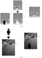
- FIG. 7 is a schematic diagram of generation of a final captured picture shown in an illustrative embodiment of the present application.
- the electronic device can extract a foreground image 71 from the captured picture, and then can fuse the foreground image 71 with a preset background image 72, by taking the foreground image 71 as the foreground, and taking the preset background image 72 as the background, to obtain a final captured picture 73.
- the method provided by the present application may further include: step 511, update the basic background image to the enhanced background image or the extended background image.
- the electronic device can perform the processing based on the updated basic background image. Since both the extended background image and the enhanced background image are images extended based on the current shooting angle, when the camera rotates, based on the updated basic background image, the background portion can still be accurately identified from the captured picture, and an accurate foreground image can be extracted.
- Step 512 send the final captured picture.
- the method provided by the embodiment can be implemented by a live broadcast terminal, which can replace the background portion in the captured picture captured by the live broadcast terminal with the preset background image selected by the user, so as to achieve the effect of background replacement.
- the live broadcast terminal after the live broadcast terminal replaces the background in the captured picture, it can upload the obtained final captured picture to the server, so that the server sends the final captured picture to each user terminal, and users can watch the final captured picture through their respective terminals.
- FIG. 8 is a schematic structural diagram of an apparatus for replacing a background in a picture shown in an illustrative embodiment of the present application.
- an apparatus 800 for replacing the background in the picture provided by the present application includes:
- the apparatus for replacing the background in the picture provided by the present application includes: an acquiring unit, configured to acquire a basic background image of a preset scene, where the basic background image is an image obtained by shooting the preset scene in advance; where the acquiring unit is further configured to acquire a captured picture obtained by currently shooting the preset scene; an identifying unit, configured to determine a current background image of the preset scene according to the basic background image and the captured picture; a background replacing unit, configured to replace the current background image in the captured picture with a preset background image to obtain a final captured picture.
- the current background image in the currently captured picture can be identified by using the basic background image captured in advance, and then the preset background image can be used to replace the current background image in the captured picture. In this way, without setting a specific background apparatus in the preset scene, the background in the captured picture can be adjusted according to requirements, thereby improving flexibility of replacing the background in the captured picture.
- FIG. 9 is a schematic structural diagram of an apparatus for replacing a background in a picture shown in another illustrative embodiment of the present application.
- the identifying unit 820 includes:
- the background determining module 823 is specifically configured to: stitch a background portion in the captured picture and the basic background image according to the matching relationship, to obtain the current background image of the preset scene in the captured picture.
- the background determining module 823 is further configured to:
- the background replacing unit 830 is specifically configured to: perform any of the following enhancement processing on the extended background image to obtain an enhanced background image:
- the background replacing unit 830 includes:
- the foreground determining module 831 is specifically configured to:
- the apparatus further includes an updating unit 840, configured to: update the basic background image to the enhanced background image or the extended background image.
- the apparatus further includes a sending unit 850, configured to: send the final captured picture.
- the device provided in this embodiment can be used to implement the technical solutions of the above method embodiments, and the implementation principles and technical effects thereof are similar, which will not be repeated here in this embodiment.
- the embodiment further provides a computer program product, including a computer program, where when the computer program is executed by a processor, the method for replacing a background in a picture according to any one of the above aspects is implemented.
- the embodiment further provides a computer program, where when the computer program is executed by a processor, the method for replacing a background in a picture according to any one of the above aspects is implemented.
- the electronic device 1000 may be a terminal device or a server.
- the terminal device may include, but is not limited to, mobile terminals, such as a mobile phone, a notebook computer, a digital broadcast receiver, a personal digital assistant (Personal Digital Assistant, PDA for short), a portable android device (Portable Android Device, PAD for short), a portable media player (Portable Media Player, PMP for short), a vehicle-mounted terminal (for example, vehicle-mounted navigation terminal), and fixed terminals, such as a digital TV, a desktop computer, etc.
- PDA Personal Digital Assistant
- PDA Personal Digital Assistant
- portable android device Portable Android Device, PAD for short
- PMP portable media player
- vehicle-mounted terminal for example, vehicle-mounted navigation terminal
- fixed terminals such as a digital TV, a desktop computer, etc.
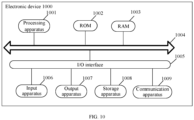
- the electronic device shown in FIG. 10 is only an example, and should not bring any limitation to the function and usage scope of the embodiments of the present disclosure.
- the electronic device 1000 may include a processing apparatus 1001 (such as a central processor, a graphics processor, etc.), which may execute suitable actions and processing according to programs stored in a read-only memory (Read Only Memory, ROM for short) 1002 or programs loaded into a random access memory (Random Access Memory, RAM for short) 1003 from a storage apparatus 1008.
- a processing apparatus 1001 such as a central processor, a graphics processor, etc.
- RAM Random Access Memory
- various programs and data required for the operation of the electronic device 1000 are also stored.
- the processing apparatus 1001, the ROM 1002, and the RAM 1003 are connected to each other through a bus 1004.
- An input/output (Input/Output, I/O for short) interface 1005 is also connected to the bus 1004.
- an input apparatus 1006 including, such as a touch screen, a touch pad, a keyboard, a mouse, a camera, a microphone, an accelerometer, a gyroscope, etc.
- an output apparatus 1007 including, such as a liquid crystal display (Liquid Crystal Display, LCD for short), a speaker, a vibrator, etc.
- a storage apparatus 1008 including, such as a magnetic tape, a hard disk, etc.
- the communication apparatus 1009 allow the electronic device 1000 to perform wireless or wired communication with other devices to exchange data.
- FIG. 10 shows the electronic device 1000 having various apparatuses, it should be understood that not all of the illustrated apparatuses are required to be implemented or provided. More or fewer apparatuses may alternatively be implemented or provided.
- an embodiment of the present disclosure includes a computer program product, which includes a computer program carried on a computer-readable medium, and the computer program contains program codes for executing the method shown in the flowchart.
- the computer program may be downloaded and installed from the network through the communication apparatus 1009, or installed from the storage apparatus 1008, or installed from the ROM 1002.
- the processing apparatus 1001 the above-mentioned functions defined in the method of the embodiment of the present disclosure are executed.
- the above-mentioned computer-readable medium in the present disclosure may be a computer-readable signal medium or a computer-readable storage medium, or any combination thereof.
- the computer-readable storage medium may be, for example, but not limited to, an electrical, a magnetic, an optical, an electromagnetic, an infrared, or a semiconductor system, apparatus, or device, or any combination thereof.
- Computer-readable storage media may include, but are not limited to, an electrical connection based on one or more wires, a portable computer disk, a hard disk, a random access memory (Random Access Memory, RAM for short), a read-only memory (Read-Only Memory, ROM for short), an erasable programmable read-only memory (Erasable Programmable Read-Only Memory, EPROM for short) or a flash memory, an optical fiber, a portable compact disk read-only memory (Compact Disc Read-Only Memory, CD-ROM for short), an optical storage device, a magnetic storage device, or any suitable combination of the above.
- a computer-readable storage medium may be any tangible medium that includes or stores programs, and the programs may be used by or in combination with an instruction execution system, apparatus, or device.
- a computer-readable signal medium may include a data signal propagated in a baseband or as a part of a carrier wave, and a computer-readable program code is carried therein. This propagated data signal can take many forms, including but not limited to an electromagnetic signal, an optical signal, or any suitable combination thereof.
- the computer readable signal medium may also be any computer readable medium other than the computer readable storage medium, the computer readable signal medium may send, propagate, or transmit the program used by or in combination with the instruction execution system, apparatus, or device.
- the program code included on the computer-readable medium can be transmitted by any suitable medium, including but not limited to: an electrical wire, an optical cable, an RF (Radio Frequency), etc., or any suitable combination thereof.
- the above-mentioned computer-readable medium may be included in the above-mentioned electronic device; or may exist alone without being assembled into the electronic device.
- the above computer-readable medium carries one or more programs, and when the foregoing one or more programs are executed by the electronic device, causes the electronic device to execute the method shown in the foregoing embodiments.
- the computer program code used to perform the operations of the present disclosure can be written in one or more programming languages or a combination thereof.
- the above-mentioned programming languages include object-oriented programming languages-such as Java, Smalltalk, C++, and also include conventional procedural programming languages-such as "C" language or similar programming language.
- the program code may be executed entirely on a computer of a user, partly on a computer of a user, executed as an independent software package, partly executed on a computer of a user and partly executed on a remote computer, or entirely executed on a remote computer or server.
- the remote computer can be connected to the user's computer through any kind of network, including a local area network (Local Area Network, LAN for short) or a wide area network (Wide Area Network, WAN for short), or it can be connected to an external computer (for example, connected via the Internet using an Internet service provider).
- LAN Local Area Network
- WAN Wide Area Network
- each block in the flowchart or block diagram may represent a module, a program segment, or a part of codes, and the module, the program segment, or the part of codes contains one or more executable instructions for implementing a designated logical function.
- the functions marked in the blocks may also occur in a different order from the order marked in the drawings. For example, two blocks shown one after another may actually be executed substantially in parallel, or sometimes may be executed in a reverse order, which depends on the functions involved.
- each block in the block diagram and/or flowchart, and the combination of the blocks in the block diagram and/or flowchart can be implemented by a dedicated hardware-based system that performs the specified functions or operations, or it can be realized by a combination of dedicated hardware and computer instructions.
- a first acquiring unit may also be described as "a unit that acquires at least two Internet Protocol addresses".
- exemplary types of hardware logic components include: a field programmable gate array (Field Programmable Gate Array, FPGA for short), an application specific integrated circuit (Application Specific Integrated Circuit, ASIC), an application specific standard product (Application Specific Standard Parts, ASSP for short), a system on chip (System on Chip, SOC for short), a complex programmable logic device (Complex Programming Logic Device, CPLD for short), etc.
- FPGA Field Programmable Gate Array
- ASIC Application Specific Integrated Circuit
- ASSP Application Specific Standard Parts
- SOC System on Chip
- CPLD Complex Programming Logic Device
- a machine-readable medium may be a tangible medium, which may include or store a program for use by or in combination with an instruction execution system, apparatus or device.
- the machine-readable medium may be a machine-readable signal medium or a machine-readable storage medium.
- the machine-readable medium may include, but is not limited to, an electronic, a magnetic, an optical, an electromagnetic, an infrared, or a semiconductor system, apparatus, or device, or any suitable combination thereof.
- machine-readable storage media may include an electrically connected portable computer disk based on one or more wires, a hard disk, a random access memory (RAM), a read-only memory (ROM), an erasable programmable read-only memory (EPROM or flash memory), an optical fiber, a portable compact disk read-only memory (CD-ROM), an optical storage device, a magnetic storage device, or any suitable combination thereof.
- RAM random access memory
- ROM read-only memory
- EPROM or flash memory erasable programmable read-only memory
- CD-ROM portable compact disk read-only memory
- magnetic storage device or any suitable combination thereof.
- a method for replacing a background in a picture including:
- the determining the current background image of the preset scene according to the basic background image and the captured picture includes:
- the determining the current background image in the captured picture according to the matching relationship includes: stitching a background portion in the captured picture and the basic background image according to the matching relationship, to obtain the current background image of the preset scene in the captured picture.
- the method further includes:
- the method further includes: performing any of the following enhancement processing on the extended background image to obtain an enhanced background image:
- the replacing the current background image in the captured picture with the preset background image to obtain the final captured picture includes:
- the determining the foreground image included in the captured picture according to the current background image and the captured picture includes:
- the method further includes: updating the basic background image to the enhanced background image or the extended background image.
- the method further includes: sending the final captured picture.
- an apparatus for replacing a background in a picture including:
- the identifying unit includes:
- the background determining module is specifically configured to: stitch a background portion in the captured picture and the basic background image according to the matching relationship, to obtain the current background image of the preset scene in the captured picture.
- the background determining module is further configured to:
- the background replacing module is specifically configured to: perform any of the following enhancement processing on the extended background image to obtain an enhanced background image:
- the background replacing module includes:
- the foreground determining module is specifically configured to:
- the apparatus further includes an updating unit, configured to: update the basic background image to the enhanced background image or the extended background image.
- the apparatus further includes a sending unit, configured to: send the final captured picture to a server.
- an electronic device including: at least one processor and a memory;
- a computer-readable storage medium has a computer-executed instruction stored thereon, and when a processor executes the computer-executed instruction, the method for replacing a background in a picture according to the above first aspect and any possible methods of the first aspect is implemented.
- a computer program product including a computer program, where when the computer program is executed by a processor, the method for replacing a background in a picture according to any of the above aspects is implemented.
- a computer program is provided, where when the computer program is executed by a processor, the method for replacing a background in a picture according to any of the above aspects is implemented.
Landscapes
- Engineering & Computer Science (AREA)
- Multimedia (AREA)
- Theoretical Computer Science (AREA)
- Physics & Mathematics (AREA)
- General Physics & Mathematics (AREA)
- Signal Processing (AREA)
- Computer Vision & Pattern Recognition (AREA)
- Databases & Information Systems (AREA)
- Software Systems (AREA)
- Artificial Intelligence (AREA)
- Health & Medical Sciences (AREA)
- Computing Systems (AREA)
- Evolutionary Computation (AREA)
- General Health & Medical Sciences (AREA)
- Medical Informatics (AREA)
- Studio Devices (AREA)
- Processing Or Creating Images (AREA)
- Studio Circuits (AREA)
- Two-Way Televisions, Distribution Of Moving Picture Or The Like (AREA)
- Image Analysis (AREA)
Abstract
Description
- The present application claims priority to
Chinese patent application No. 202110518684.4, entitled "METHOD FOR REPLACING BACKGROUND IN PICTURE, DEVICE, STORAGE MEDIUM AND PROGRAM PRODUCT" and filed on May 12, 2021 - Embodiments of the present disclosure relate to image processing technologies, and in particular, to a method for replacing a background in a picture, a device, a storage medium, and a program product.
- With development of network technology, live webcasting is becoming more and more popular at present, and the content of live broadcast is also becoming more and more abundant. For example, information of an object can be introduced to a viewer through the live webcasting.
- At present, a background needs to be set during the live webcasting. For example, a projection screen or TV can be placed behind a host to display information through the projection screen or TV
- However, if the projection screen or TV is set, there may be reflections in a captured live broadcast picture, which causes the live broadcast picture unclear.
- Embodiments of the present disclosure provide a method for replacing a background in a picture, a device, a storage medium, and a program product, so as to solve the problem in the prior art that a specific device needs to be set as a live broadcast background, which results in high cost of the live broadcast, and that the specific device may cause the live broadcast picture unclear.
- In a first aspect, an embodiment of the present disclosure provides a method for replacing a background in a picture, including:
- acquiring a basic background image of a preset scene, where the basic background image is an image obtained by shooting the preset scene in advance;
- acquiring a captured picture obtained by currently shooting the preset scene, and determining a current background image of the preset scene according to the basic background image and the captured picture; and
- replacing the current background image in the captured picture with a preset background image to obtain a final captured picture.
- In a second aspect, an embodiment of the present disclosure provides an apparatus for replacing a background in a picture, including:
- an acquiring unit, configured to acquire a basic background image of a preset scene, where the basic background image is an image obtained by shooting the preset scene in advance;
- where the acquiring unit is further configured to acquire a captured picture obtained by currently shooting the preset scene;
- an identifying unit, configured to determine a current background image of the preset scene according to the basic background image and the captured picture; and
- a background replacing unit, configured to replace the current background image in the captured picture with a preset background image to obtain a final captured picture.
- In a third aspect, an embodiment of the present disclosure provides an electronic device, including: at least one processor and a memory;
- where the memory stores a computer-executed instruction; and
- the at least one processor executes the computer-executed instruction stored in the memory, to cause the at least one processor to execute the method for replacing a background in a picture according to the first aspect.
- In a fourth aspect, an embodiment of the present disclosure provides a computer-readable storage medium which has a computer-executed instruction stored thereon, and when a processor executes the computer-executed instruction, the method for replacing a background in a picture according to the first aspect is implemented.
- In a fifth aspect, an embodiment of the present disclosure provides a computer program product, including a computer program, where when the computer program is executed by a processor, the method for replacing a background in a picture according to the first aspect is implemented.
- In a sixth aspect, an embodiment of the present disclosure provides a computer program, where when the computer program is executed by a processor, the method for replacing a background in a picture according to the first aspect is implemented.
- A method for replacing a background in a picture, a device, a storage medium and a program product provided in the embodiments include: acquiring a basic background image of a preset scene, where the basic background image is an image obtained by shooting the preset scene in advance; acquiring a captured picture obtained by currently shooting the preset scene, and determining a current background image of the preset scene according to the basic background image and the captured picture; replacing the current background image in the captured picture with a preset background image to obtain a final captured picture. In the solution provided by the embodiments, the current background image in the currently captured picture can be identified by using the basic background image captured in advance, and then the preset background image can be used to replace the current background image in the captured picture. In such a way, without setting a specific background apparatus in the preset scene, the background in the captured picture can be adjusted according to requirements, thereby improving flexibility of replacing the background in the captured picture.
- In order to describe the technical solutions in embodiments of the present disclosure or prior art more clearly, the following will briefly introduce drawings that need to be used in the description of the embodiments or prior art. Obviously, the drawings described below are some embodiments of the present disclosure, and for those of skilled in the art, other drawings can be obtained based on these drawings without creative efforts.
-
FIG. 1 is a schematic diagram of a live broadcast picture shown in an illustrative embodiment. -
FIG. 2 is a schematic diagram of a live broadcast picture shown in another illustrative embodiment. -
FIG. 3 is a schematic flowchart of a method for replacing a background in a picture shown in an illustrative embodiment of the present application. -
FIG. 4 is a schematic diagram of a basic background image shown in an illustrative embodiment of the present application. -
FIG. 5 is a schematic flowchart of a method for replacing a background in a picture shown in another illustrative embodiment of the present application. -
FIG. 6 is a schematic diagram of a background image shown in an illustrative embodiment of the present application. -
FIG. 7 is a schematic diagram of generation of a final captured picture shown in an illustrative embodiment of the present application. -
FIG. 8 is a schematic structural diagram of an apparatus for replacing a background in a picture shown in an illustrative embodiment of the present application. -
FIG. 9 is a schematic structural diagram of an apparatus for replacing a background in a picture shown in another illustrative embodiment of the present application. -
FIG. 10 is a schematic hardware structural diagram of an electronic device provided by an embodiment of the present disclosure. - In order to make the purpose, technical solutions and advantages of embodiments of the present disclosure clearer, the technical solutions in the embodiments of the present disclosure will be described as follows clearly and completely in conjunction with accompanying drawings in the embodiments of the present disclosure. Apparently, the described embodiments are a part rather than all of the embodiments of the present disclosure. Based on the embodiments in the present disclosure, all the other embodiments acquired by those skilled in the art without delivering creative efforts shall fall into the protection scope of the present disclosure.
-
FIG. 1 is a schematic diagram of a live broadcast picture shown in an illustrative embodiment. - As shown in
FIG. 1 , alive broadcast picture 11 can be displayed on a client side, and there exists aTV 12 in the live broadcast picture. - In order to display information, the TV 12 may be set in a live broadcast site, and live broadcast information may be displayed through the TV 12. However, there may be reflections on the TV, which may cause the live broadcast image unclear.
-
FIG. 2 is a schematic diagram of a live broadcast picture shown in another illustrative embodiment. - As shown in
FIG. 2 , alive broadcast picture 21 may be displayed on the client side, and there exists a background 22 (shown by oblique lines) in the live broadcast picture. For example, thebackground 22 may be a preset image. - A green screen 23 (shown by a blank region) can be set at the live broadcast site. Specifically, the green screen is set at the back of a host as a background, and the green screen in the picture is replaced by a preset image via software.
- However, this method requires the preparation of live broadcast consumables, resulting in a higher cost for live broadcast.
- In order to solve the above technical problems, in the solution provided by the present application, a basic background image of a preset scene can be shot in advance, and a background in a captured picture can be identified by using the basic background image, and then a preset background image can be used to accurately replace the background in the captured picture. This method does not need to set a background such as the green screen, and the TV on the live broadcast site, so that the cost of live broadcast is reduced, and the pictured would not be unclear due to the problem, such as, TV reflections.
-
FIG. 3 is a schematic flowchart of a method for replacing a background in a picture shown in an illustrative embodiment of the present application. - As shown in
FIG. 3 , the method for replacing the background in the picture provided by the present application includes:
step 301, acquire a basic background image of a preset scene, where the basic background image is an image obtained by shooting the preset scene in advance. - The method provided in the present application may be executed by an electronic device with computing capability.
- In an implementation, the electronic device may be, for example, a computer, and the computer may be, for example, a backstage server that provides a live broadcast service.
- In another implementation, the electronic device may be, for example, a mobile terminal, and the mobile terminal may serve as a live broadcast terminal of the host.
- Specifically, the method provided in the present application may be set in the electronic device, so that the electronic device executes the method provided in the present application.
- Furthermore, when the electronic device replaces a picture background, it can acquire the basic background image. The basic background image is an image obtained by capturing a preset scene in advance. For example, a user can shoot a scene where the live broadcast is located, and thus obtain the basic background image. Specifically, the basic background image can be shot from a shooting angle during the live broadcast.
- For another example, the method provided by the present application can also perform background replacement on a video recorded in the preset scene, or perform background replacement on a picture shot in the preset scene.
- In practical application, when the basic background image is captured, there, in the preset scene, may be only an environment where the live broadcast is located but without a character.
-
FIG. 4 is a schematic diagram of a basic background image shown in an illustrative embodiment of the present application. - As shown in
FIG. 4 , the basic background image can be shown inFIG. 4 . The host can perform the live broadcast in this scene. Generally, the environment will not be changed during the live broadcast, so the background of the live broadcast picture will not be much different from the basic background image. Therefore, the background portion in the live broadcast picture can be identified based on the basic background image. -
Step 302, acquire a captured picture obtained by currently shooting the preset scene, and determine a current background image of the preset scene according to the basic background image and the captured picture. - The electronic device can acquire the captured picture obtained by currently shooting the preset scene, and the captured picture may be shot in real time or in advance. The captured picture may be a frame in a video, or an image shot.
- Since the captured picture is a picture obtained by shooting the preset scene, the captured picture includes image content in the basic background image. For example, if the host is performing the live broadcast in the preset scene, the captured picture includes the host and part of the basic background image.
- Specifically, the captured picture is a picture in which the background needs to be replaced. Therefore, the electronic device can acquire the captured picture, and determine the current background image of the preset scene according to the basic background image and the captured picture.
- Furthermore, the electronic device can compare the basic background image with the captured picture, so as to identify a portion, consistent with the basic background picture, in the captured picture, to obtain the current background image.
-
Step 303, replace the current background image in the captured picture with a preset background image to obtain a final captured picture. - In practical application, the user can also set the preset background image in advance. If the electronic device is a server, the user can upload the preset background image through a terminal; if the electronic device is a live broadcast client, the user can select an image in the live broadcast client as the preset background image.
- The electronic device can use the selected preset background image to replace the current background image in the captured picture, so as to obtain the final captured picture. Specifically, a foreground image can be extracted from the captured picture by using the current background image, and the foreground image is stitched into the preset background image to obtain the final captured picture.
- Specifically, the user can also replace the preset background image, so as to replace the background of the live broadcast during the live broadcast according to the needs. For example, when introducing item A, the user may select an image including introduction information of the item A as the preset background image, and when introducing item B, the user may select an image including introduction information of the item B as the preset background image. In this way, the user can adjust the background image for the live broadcast according to the user's needs.
- If the electronic device is a server, the server may send the final captured picture with the updated background to each user terminal, so that the user can watch the final captured picture with the replaced background.
- If the electronic device is a live broadcast terminal, the live broadcast terminal can send the final captured picture with the updated background to the server, and the server sends the final captured picture to the user terminal, so that the user can watch the final captured picture with the replaced background.
- The method for replacing the background in the picture provided by the present application includes: acquiring a basic background image of a preset scene, where the basic background image is an image obtained by shooting the preset scene in advance; acquiring a captured picture obtained by currently shooting the preset scene, and determining a current background image of the preset scene according to the basic background image and the captured picture; replacing the current background image in the captured picture with a preset background image to obtain a final captured picture. In the method provided by the present application, the current background image in the currently captured picture can be identified by using the basic background image captured in advance, and then the preset background image can be used to replace the current background image in the captured picture. In this way, without setting a specific background apparatus in the preset scene, the background in the captured picture can be adjusted according to requirements, thereby improving flexibility of replacing the background in the captured picture.
-
FIG. 5 is a schematic flowchart of a method for replacing a background in a picture shown in another illustrative embodiment of the present application. - As shown in
FIG. 5 , the method for replacing the background in the picture provided by the present application includes:
step 501, acquire a basic background image of a preset scene, where the basic background image is an image obtained by shooting the preset scene in advance. - The implementation and principle of
step 501 are similar to those ofstep 301, which will not be repeated here. -
Step 502, acquire a captured picture obtained by currently shooting the preset scene. - The manner of acquiring the captured picture in
step 502 is similar to that instep 302, which will not be repeated here. -
Step 503, extract basic feature point information of the basic background image, and extract shooting feature point information in the captured picture. - The electronic device can identify the current background image in the captured picture according to the basic background image. Specifically, feature point information in the basic background image and in the captured picture can be extracted respectively.
- Specifically, the extracted basic feature point information can represent a feature of the basic background image, and the extracted shooting feature point information can represent a feature in the captured picture. The feature point information can be used to identify the portion in the captured picture which is consistent with the basic background image, and then the current background image is identified.
- Furthermore, the electronic device can use a scale invariant feature transform (Scale Invariant Feature Transform, SIFT) method to extract the features in the basic background image and the captured picture, to obtain the basic feature point information in the basic background image, and the shooting feature point information in the captured picture.
-
Step 504, determine a matching relationship between each piece of the basic feature point information and each piece of the shooting feature point information, and determine the current background image in the captured picture according to the matching relationship. - In practical application, the electronic device can match the basic feature point information with the shooting feature point information, so as to determine the matching relationship between each piece of basic feature point information and each piece of shooting feature point information. For example, basic feature point information A1 is matched with shooting feature point information A2, and basic feature point information B1 is matched with shooting feature point information B2.
- If the feature point information is extracted according to the SIFT method, each piece of feature point information extracted can represent a stable local feature of the image, and then a stable matching result can be obtained according to the SIFT feature point.
- Specifically, the electronic device may determine the current background image in the captured picture according to the matching relationship.
- Furthermore, the electronic device can determine a positional corresponding relationship between the basic background image and the captured picture according to the matching relationship between each piece of basic feature point information and each piece of shooting feature point information. For example, pixel point P1 of the basic background image is matched with pixel point P2 in the captured picture. It can be considered that the pixel point P2 is the background portion, and there is a corresponding relationship between the positions of these two pixel points.
- In practical application, the electronic device can determine the background portion in the captured picture according to the positional corresponding relationship between the basic background image and the captured picture, and can stitch the background portion in the captured picture and the basic background picture to obtain the current background image of the preset scene in the captured picture.
- A camera position at a time of currently shooting the preset scene may not be exactly the same as a camera position at a time of capturing the basic background image, so the background portion in the captured picture may not completely coincide with the basic background image. Therefore, the basic background image can be stitched with the captured picture, to obtain a larger background image.
- For example, if the camera position at the time of currently shooting the preset scene is higher than the camera position at the time of capturing the basic background image, image content of an upper part of the captured picture can be stitched onto the basic background image, to obtain a larger stitched background image.
-
FIG. 6 is a schematic diagram of a background image shown in an illustrative embodiment of the present application. - As shown in
FIG. 6 , a basic background image is shown as 61, and abackground portion 63 is identified in a capturedpicture 62, and thebackground portion 63 and thebasic background image 61 can be stitched together to obtain acurrent background image 64. - Step 507 and step 510 may be executed after
step 504, so as to generate a final captured picture directly according to the current background image. -
Step 505, extend a boundary of the current background image to obtain an extended background image. - In an optional implementation, the solution provided in the present application may also extend the boundary of the current background image to obtain an extended background image.
- In this implementation, when a camera angle changes, the method provided by the present application can also accurately identify the background portion in the captured picture according to the extended background image.
- In this implementation, the preset background image may be used to replace the extended background image in the captured picture according to the extended background image, to obtain the final captured picture. Specifically, the background portion can be identified in the captured picture according to the extended background image, so as to extract the foreground image, and then the foreground image is used to generate the final captured picture.
- Step 508 and step 510 may be executed after
step 505, so as to generate the final captured picture according to the extended background image. -
Step 506, perform any of the following enhancement processing on the extended background image to obtain an enhanced background image: stitching seam feathering, light transformation. - In an optional implementation, the method provided in the present application can further perform enhancement processing on the extended background image to obtain an enhanced background image, so that the enhanced background image is more similar to the background portion in the captured picture. Therefore, the background portion can be accurately identified from the captured picture according to the enhanced background image.
- In this implementation, the preset background image may be used to replace the enhanced background image in the captured picture according to the enhanced background image, to obtain the final captured picture. Specifically, the background portion can be identified from the captured picture according to the enhanced background image, so as to extract the foreground image, and then the foreground image is used to generate the final captured picture.
- Specifically, the stitching seam feathering processing can be performed on the extended background image, so that the position transition of the stitching seam in the image is more natural. It is also possible to perform light change processing on the extended background image, so as to increase brightness in the image and enhance a texture feature in the image.
- Specifically, the electronic device may determine a foreground image included in the captured picture according to the current background image and the captured picture. Specifically, the foreground image in the captured picture may be directly extracted according to the current background image, or the foreground image in the captured picture may be extracted by using the extended background image determined according to the current background image. The foreground image in the captured picture may also be extracted by using the enhanced scene image determined according to the current background image.
- Step 509 and step 510 may be executed after
step 506, so as to generate the final captured picture according to the enhanced background image. -
Step 507, input the current background image and the captured picture into a preset segmentation model, where the preset segmentation model is used to output the foreground image included in the captured picture. - The electronic device can set a model, which can output the foreground image included in the captured picture according to the background image and the captured picture. The model can be obtained through pre-training. For example, a preset model can be built in advance and then trained to obtain the preset segmentation model. A feature extraction network in the preset model can be, for example, a mobilenet network (mobile neural network).
- Using the mobilenet network to build the preset model can make a size of the model smaller, so that the model can be applied to the mobile terminal side.
- In an optional implementation, the electronic device may input the current background image and the captured image into the preset segmentation model, and the preset segmentation model can output the foreground image.
-
Step 508, input the extended background image, which is determined according to the current background image, and the captured picture into a preset segmentation model, where the preset segmentation model is used to output the foreground image included in the captured picture. - The electronic device can set a model, which can output the foreground image included in the captured picture according to the background image and the captured picture. The model can be obtained through pre-training. For example, a preset model can be built in advance and then trained to obtain the preset segmentation model. A feature extraction network in the preset model can be, for example, a mobilenet network.
- Using the mobilenet network to build the preset model can make a size of the model smaller, so that the model can be applied to the mobile terminal side.
- In an optional implementation, the electronic device may input the extended background image and the captured image into the preset segmentation model, and the preset segmentation model can output the foreground image.
-
Step 509, input the enhanced background image, which is determined according to the current background image, and the captured picture into a preset segmentation model, where the preset segmentation model is used to output the foreground image included in the captured picture. - The electronic device can set a model, which can output the foreground image included in the captured picture according to the background image and the captured picture. The model can be obtained through pre-training. For example, a preset model can be built in advance and then trained to obtain the preset segmentation model. A feature extraction network in the preset model can be, for example, a mobilenet network.
- Using the mobilenet network to build the preset model can make a size of the model smaller, so that the model can be applied to the mobile terminal side.
- In an optional implementation, the electronic device may input the enhanced background image and the captured image into the preset segmentation model, and the preset segmentation model can output the foreground image.
- Step 510: generate the final captured picture according to the foreground image and the preset background image, where a background of the final captured picture is the preset background image, and a foreground of the final captured picture is the foreground image.
- Specifically, the electronic device may fuse the foreground image and the acquired preset background image to obtain the final captured picture. In this way, the background in the picture can be shot better, and on basis of the method of the present application, the background portion in the captured picture can be identified accurately, and then an accurate foreground image can be extracted, so that a clear final captured picture can be obtained.
-
FIG. 7 is a schematic diagram of generation of a final captured picture shown in an illustrative embodiment of the present application. - As shown in
FIG. 7 , the electronic device can extract aforeground image 71 from the captured picture, and then can fuse theforeground image 71 with apreset background image 72, by taking theforeground image 71 as the foreground, and taking thepreset background image 72 as the background, to obtain a final capturedpicture 73. - In an optional implementation, the method provided by the present application may further include:
step 511, update the basic background image to the enhanced background image or the extended background image. - When continuing to replace the background for the captured picture, the electronic device can perform the processing based on the updated basic background image. Since both the extended background image and the enhanced background image are images extended based on the current shooting angle, when the camera rotates, based on the updated basic background image, the background portion can still be accurately identified from the captured picture, and an accurate foreground image can be extracted.
-
Step 512, send the final captured picture. - The method provided by the embodiment can be implemented by a live broadcast terminal, which can replace the background portion in the captured picture captured by the live broadcast terminal with the preset background image selected by the user, so as to achieve the effect of background replacement.
- Specifically, after the live broadcast terminal replaces the background in the captured picture, it can upload the obtained final captured picture to the server, so that the server sends the final captured picture to each user terminal, and users can watch the final captured picture through their respective terminals.
-
FIG. 8 is a schematic structural diagram of an apparatus for replacing a background in a picture shown in an illustrative embodiment of the present application. - As shown in
FIG. 8 , anapparatus 800 for replacing the background in the picture provided by the present application includes: - an acquiring
unit 810, configured to acquire a basic background image of a preset scene, where the basic background image is an image obtained by shooting the preset scene in advance; - where the acquiring
unit 810 is further configured to acquire a captured picture obtained by currently shooting the preset scene; - an identifying
unit 820, configured to determine a current background image of the preset scene according to the basic background image and the captured picture; and - a
background replacing unit 830, configured to replace the current background image in the captured picture with a preset background image to obtain a final captured picture. - The apparatus for replacing the background in the picture provided by the present application includes: an acquiring unit, configured to acquire a basic background image of a preset scene, where the basic background image is an image obtained by shooting the preset scene in advance; where the acquiring unit is further configured to acquire a captured picture obtained by currently shooting the preset scene; an identifying unit, configured to determine a current background image of the preset scene according to the basic background image and the captured picture; a background replacing unit, configured to replace the current background image in the captured picture with a preset background image to obtain a final captured picture. In the apparatus provided by the present application, the current background image in the currently captured picture can be identified by using the basic background image captured in advance, and then the preset background image can be used to replace the current background image in the captured picture. In this way, without setting a specific background apparatus in the preset scene, the background in the captured picture can be adjusted according to requirements, thereby improving flexibility of replacing the background in the captured picture.
-
FIG. 9 is a schematic structural diagram of an apparatus for replacing a background in a picture shown in another illustrative embodiment of the present application. - As shown in
FIG. 9 , on the basis of the above-mentioned embodiments, in anapparatus 900 for replacing a background in a picture provided by the present application, in an optional implementation manner, the identifyingunit 820 includes: - a
feature extracting module 821, configured to extract basic feature point information of the basic background image, and extract shooting feature point information in the captured picture; - a
matching module 822, configured to determine a matching relationship between each piece of the basic feature point information and each piece of the shooting feature point information; - a
background determining module 823, configured to determine the current background image in the captured picture according to the matching relationship. - In an optional implementation, the
background determining module 823 is specifically configured to:
stitch a background portion in the captured picture and the basic background image according to the matching relationship, to obtain the current background image of the preset scene in the captured picture. - In an optional implementation, the
background determining module 823 is further configured to: - extend a boundary of the current background image to obtain an extended background image; and
- correspondingly, the
background replacing unit 830 is specifically configured to:
replace the extended background image in the captured picture with the preset background image according to the extended background image, to obtain the final captured picture. - In an optional implementation, the
background replacing unit 830 is specifically configured to:
perform any of the following enhancement processing on the extended background image to obtain an enhanced background image: - stitching seam feathering, light transformation; and
- correspondingly, the
background replacing unit 830 is specifically configured to: - replace the extended background image in the captured picture with the preset background image according to the enhanced background image, to obtain the final captured picture.
- In an optional implementation, the
background replacing unit 830 includes: - a
foreground determining module 831, configured to determine a foreground image included in the captured picture according to the current background image and the captured picture; and - a
picture generating module 832, configured to generate the final captured picture according to the foreground image and the preset background image, where a background of the final captured picture is the preset background image, and a foreground of the final captured picture is the foreground image. - In an optional implementation, the
foreground determining module 831 is specifically configured to: - input the current background image and the captured picture into a preset segmentation model, where the preset segmentation model is used to output the foreground image included in the captured picture;
- or, input the extended background image, which is determined according to the current background image, and the captured picture into a preset segmentation model, where the preset segmentation model is used to output the foreground image included in the captured picture;
- or, input the enhanced background image, which is determined according to the current background image, and the captured picture into a preset segmentation model, where the preset segmentation model is used to output the foreground image included in the captured picture.
- In an optional implementation, the apparatus further includes an updating
unit 840, configured to:
update the basic background image to the enhanced background image or the extended background image. - In an optional implementation, the apparatus further includes a sending
unit 850, configured to:
send the final captured picture. - The device provided in this embodiment can be used to implement the technical solutions of the above method embodiments, and the implementation principles and technical effects thereof are similar, which will not be repeated here in this embodiment.
- The embodiment further provides a computer program product, including a computer program, where when the computer program is executed by a processor, the method for replacing a background in a picture according to any one of the above aspects is implemented.
- The embodiment further provides a computer program, where when the computer program is executed by a processor, the method for replacing a background in a picture according to any one of the above aspects is implemented.
- Referred to
FIG. 10 , which shows a schematic structural diagram of anelectronic device 1000 adaptable to implementing the embodiments of the present disclosure. Theelectronic device 1000 may be a terminal device or a server. The terminal device may include, but is not limited to, mobile terminals, such as a mobile phone, a notebook computer, a digital broadcast receiver, a personal digital assistant (Personal Digital Assistant, PDA for short), a portable android device (Portable Android Device, PAD for short), a portable media player (Portable Media Player, PMP for short), a vehicle-mounted terminal (for example, vehicle-mounted navigation terminal), and fixed terminals, such as a digital TV, a desktop computer, etc. The electronic device shown inFIG. 10 is only an example, and should not bring any limitation to the function and usage scope of the embodiments of the present disclosure. - As shown in
FIG. 10 , theelectronic device 1000 may include a processing apparatus 1001 (such as a central processor, a graphics processor, etc.), which may execute suitable actions and processing according to programs stored in a read-only memory (Read Only Memory, ROM for short) 1002 or programs loaded into a random access memory (Random Access Memory, RAM for short) 1003 from astorage apparatus 1008. In theRAM 1003, various programs and data required for the operation of theelectronic device 1000 are also stored. Theprocessing apparatus 1001, theROM 1002, and theRAM 1003 are connected to each other through abus 1004. An input/output (Input/Output, I/O for short)interface 1005 is also connected to thebus 1004. - Generally, the following apparatuses can be connected to the I/O interface 1005: an
input apparatus 1006 including, such as a touch screen, a touch pad, a keyboard, a mouse, a camera, a microphone, an accelerometer, a gyroscope, etc.; anoutput apparatus 1007 including, such as a liquid crystal display (Liquid Crystal Display, LCD for short), a speaker, a vibrator, etc.; astorage apparatus 1008 including, such as a magnetic tape, a hard disk, etc.; and acommunication apparatus 1009. Thecommunication apparatus 1009 allow theelectronic device 1000 to perform wireless or wired communication with other devices to exchange data. AlthoughFIG. 10 shows theelectronic device 1000 having various apparatuses, it should be understood that not all of the illustrated apparatuses are required to be implemented or provided. More or fewer apparatuses may alternatively be implemented or provided. - In particular, according to an embodiment of the present disclosure, the process described above with reference to the flowchart may be implemented as a computer software program. For example, an embodiment of the present disclosure includes a computer program product, which includes a computer program carried on a computer-readable medium, and the computer program contains program codes for executing the method shown in the flowchart. In such an embodiment, the computer program may be downloaded and installed from the network through the
communication apparatus 1009, or installed from thestorage apparatus 1008, or installed from theROM 1002. When the computer program is executed by theprocessing apparatus 1001, the above-mentioned functions defined in the method of the embodiment of the present disclosure are executed. - It should be noted that the above-mentioned computer-readable medium in the present disclosure may be a computer-readable signal medium or a computer-readable storage medium, or any combination thereof. The computer-readable storage medium may be, for example, but not limited to, an electrical, a magnetic, an optical, an electromagnetic, an infrared, or a semiconductor system, apparatus, or device, or any combination thereof. More specific examples of computer-readable storage media may include, but are not limited to, an electrical connection based on one or more wires, a portable computer disk, a hard disk, a random access memory (Random Access Memory, RAM for short), a read-only memory (Read-Only Memory, ROM for short), an erasable programmable read-only memory (Erasable Programmable Read-Only Memory, EPROM for short) or a flash memory, an optical fiber, a portable compact disk read-only memory (Compact Disc Read-Only Memory, CD-ROM for short), an optical storage device, a magnetic storage device, or any suitable combination of the above. In the present disclosure, a computer-readable storage medium may be any tangible medium that includes or stores programs, and the programs may be used by or in combination with an instruction execution system, apparatus, or device. In the present disclosure, a computer-readable signal medium may include a data signal propagated in a baseband or as a part of a carrier wave, and a computer-readable program code is carried therein. This propagated data signal can take many forms, including but not limited to an electromagnetic signal, an optical signal, or any suitable combination thereof. The computer readable signal medium may also be any computer readable medium other than the computer readable storage medium, the computer readable signal medium may send, propagate, or transmit the program used by or in combination with the instruction execution system, apparatus, or device. The program code included on the computer-readable medium can be transmitted by any suitable medium, including but not limited to: an electrical wire, an optical cable, an RF (Radio Frequency), etc., or any suitable combination thereof.
- The above-mentioned computer-readable medium may be included in the above-mentioned electronic device; or may exist alone without being assembled into the electronic device.
- The above computer-readable medium carries one or more programs, and when the foregoing one or more programs are executed by the electronic device, causes the electronic device to execute the method shown in the foregoing embodiments.
- The computer program code used to perform the operations of the present disclosure can be written in one or more programming languages or a combination thereof. The above-mentioned programming languages include object-oriented programming languages-such as Java, Smalltalk, C++, and also include conventional procedural programming languages-such as "C" language or similar programming language. The program code may be executed entirely on a computer of a user, partly on a computer of a user, executed as an independent software package, partly executed on a computer of a user and partly executed on a remote computer, or entirely executed on a remote computer or server. In the case of a remote computer, the remote computer can be connected to the user's computer through any kind of network, including a local area network (Local Area Network, LAN for short) or a wide area network (Wide Area Network, WAN for short), or it can be connected to an external computer (for example, connected via the Internet using an Internet service provider).
- The flowcharts and block diagrams in the accompanying drawings illustrate possible implemented architecture, functions, and operations of the system, method, computer program and computer program product according to the embodiments of the present disclosure. In this point, each block in the flowchart or block diagram may represent a module, a program segment, or a part of codes, and the module, the program segment, or the part of codes contains one or more executable instructions for implementing a designated logical function. It should also be noted that, in some alternative implementations, the functions marked in the blocks may also occur in a different order from the order marked in the drawings. For example, two blocks shown one after another may actually be executed substantially in parallel, or sometimes may be executed in a reverse order, which depends on the functions involved. It should also be noted that each block in the block diagram and/or flowchart, and the combination of the blocks in the block diagram and/or flowchart, can be implemented by a dedicated hardware-based system that performs the specified functions or operations, or it can be realized by a combination of dedicated hardware and computer instructions.
- The units involved in the embodiments described in the present disclosure may be implemented in software or hardware. Where a name of a unit does not constitute a limitation on the unit itself in one case. For example, a first acquiring unit may also be described as "a unit that acquires at least two Internet Protocol addresses".
- The functions described herein above may be performed at least in part by one or more hardware logic components. For example, non-restrictively, exemplary types of hardware logic components that may be used include: a field programmable gate array (Field Programmable Gate Array, FPGA for short), an application specific integrated circuit (Application Specific Integrated Circuit, ASIC), an application specific standard product (Application Specific Standard Parts, ASSP for short), a system on chip (System on Chip, SOC for short), a complex programmable logic device (Complex Programming Logic Device, CPLD for short), etc.
- In the context of the present disclosure, a machine-readable medium may be a tangible medium, which may include or store a program for use by or in combination with an instruction execution system, apparatus or device. The machine-readable medium may be a machine-readable signal medium or a machine-readable storage medium. The machine-readable medium may include, but is not limited to, an electronic, a magnetic, an optical, an electromagnetic, an infrared, or a semiconductor system, apparatus, or device, or any suitable combination thereof. More specific examples of the machine-readable storage media may include an electrically connected portable computer disk based on one or more wires, a hard disk, a random access memory (RAM), a read-only memory (ROM), an erasable programmable read-only memory (EPROM or flash memory), an optical fiber, a portable compact disk read-only memory (CD-ROM), an optical storage device, a magnetic storage device, or any suitable combination thereof.
- In a first aspect, according to one or more embodiments of the present disclosure, a method for replacing a background in a picture is provided, including:
- acquiring a basic background image of a preset scene, where the basic background image is an image obtained by shooting the preset scene in advance;
- acquiring a captured picture obtained by currently shooting the preset scene, and determining a current background image of the preset scene according to the basic background image and the captured picture; and
- replacing the current background image in the captured picture with a preset background image to obtain a final captured picture.
- According to one or more embodiments of the present disclosure, the determining the current background image of the preset scene according to the basic background image and the captured picture includes:
- extracting basic feature point information of the basic background image, and extracting shooting feature point information in the captured picture; and
- determining a matching relationship between each piece of the basic feature point information and each piece of the shooting feature point information, and determining the current background image in the captured picture according to the matching relationship.
- According to one or more embodiments of the present disclosure, the determining the current background image in the captured picture according to the matching relationship includes:
stitching a background portion in the captured picture and the basic background image according to the matching relationship, to obtain the current background image of the preset scene in the captured picture. - According to one or more embodiments of the present disclosure, the method further includes:
- extending a boundary of the current background image to obtain an extended background image; and
- replacing the extended background image in the captured picture with the preset background image correspondingly according to the extended background image, to obtain the final captured picture.
- According to one or more embodiments of the present disclosure, the method further includes:
performing any of the following enhancement processing on the extended background image to obtain an enhanced background image: - stitching seam feathering, light transformation; and
- replacing the extended background image in the captured picture with the preset background image correspondingly according to the enhanced background image, to obtain the final captured picture.
- According to one or more embodiments of the present disclosure, the replacing the current background image in the captured picture with the preset background image to obtain the final captured picture includes:
- determining a foreground image included in the captured picture according to the current background image and the captured picture; and
- generating the final captured picture according to the foreground image and the preset background image, where a background of the final captured picture is the preset background image, and a foreground of the final captured picture is the foreground image.
- According to one or more embodiments of the present disclosure, the determining the foreground image included in the captured picture according to the current background image and the captured picture includes:
- inputting the current background image and the captured picture into a preset segmentation model, where the preset segmentation model is used to output the foreground image included in the captured picture;
- or, inputting the extended background image, which is determined according to the current background image, and the captured picture into a preset segmentation model, where the preset segmentation model is used to output the foreground image included in the captured picture;
- or, inputting the enhanced background image, which is determined according to the current background image, and the captured picture into a preset segmentation model, where the preset segmentation model is used to output the foreground image included in the captured picture.
- According to one or more embodiments of the present disclosure, the method further includes:
updating the basic background image to the enhanced background image or the extended background image. - According to one or more embodiments of the present disclosure, the method further includes:
sending the final captured picture. - In a second aspect, according to one or more embodiments of the present disclosure, an apparatus for replacing a background in a picture is provided, including:
- an acquiring unit, configured to acquire a basic background image of a preset scene, where the basic background image is an image obtained by shooting the preset scene in advance;
- where the acquiring unit is further configured to acquire a captured picture obtained by currently shooting the preset scene;
- an identifying unit, configured to determine a current background image of the preset scene according to the basic background image and the captured picture; and
- a background replacing unit, configured to replace the current background image in the captured picture with a preset background image to obtain a final captured picture.
- According to one or more embodiments of the present disclosure, the identifying unit includes:
- a feature extracting module, configured to extract basic feature point information of the basic background image, and extracting shooting feature point information in the captured picture;
- a matching module, configured to determine a matching relationship between each piece of the basic feature point information and each piece of the shooting feature point information; and
- a background determining module, configured to determine the current background image in the captured picture according to the matching relationship.
- According to one or more embodiments of the present disclosure, the background determining module is specifically configured to:
stitch a background portion in the captured picture and the basic background image according to the matching relationship, to obtain the current background image of the preset scene in the captured picture. - According to one or more embodiments of the present disclosure, the background determining module is further configured to:
- extend a boundary of the current background image to obtain an extended background image; and
- correspondingly, the background replacing unit is specifically configured to:
replace the extended background image in the captured picture with the preset background image according to the extended background image, to obtain the final captured picture. - According to one or more embodiments of the present disclosure, the background replacing module is specifically configured to:
perform any of the following enhancement processing on the extended background image to obtain an enhanced background image: - stitching seam feathering, light transformation; and
- correspondingly, the background replacing unit is specifically configured to:
- replace the extended background image in the captured picture with the preset background image according to the enhanced background image, to obtain the final captured picture.
- According to one or more embodiments of the present disclosure, the background replacing module includes:
- a foreground determining module, configured to determine a foreground image included in the captured picture according to the current background image and the captured picture; and
- a picture generating module, configured to generate the final captured picture according to the foreground image and the preset background image, where a background of the final captured picture is the preset background image, and a foreground of the final captured picture is the foreground image.
- According to one or more embodiments of the present disclosure, the foreground determining module is specifically configured to:
- input the current background image and the captured picture into a preset segmentation model, and the preset segmentation model is used to output the foreground image included in the captured picture;
- or, input the extended background image, which is determined according to the current background image, and the captured picture into a preset segmentation model, where the preset segmentation model is used to output the foreground image included in the captured picture;
- or, input the enhanced background image, which is determined according to the current background image, and the captured picture into a preset segmentation model, where the preset segmentation model is used to output the foreground image included in the captured picture.
- According to one or more embodiments of the present disclosure, the apparatus further includes an updating unit, configured to:
update the basic background image to the enhanced background image or the extended background image. - According to one or more embodiments of the present disclosure, the apparatus further includes a sending unit, configured to:
send the final captured picture to a server. - In a third aspect, according to one or more embodiments of the present disclosure, an electronic device is provided, including: at least one processor and a memory;
- where the memory stores a computer-executed instruction;
- the at least one processor executes the computer-executed instruction stored in the memory, to cause the at least one processor to execute the method for replacing a background in a picture according to the above first aspect and any possible methods of the first aspect.
- In a fourth aspect, according to one or more embodiments of the present disclosure, a computer-readable storage medium is provided. The computer-readable storage medium has a computer-executed instruction stored thereon, and when a processor executes the computer-executed instruction, the method for replacing a background in a picture according to the above first aspect and any possible methods of the first aspect is implemented.
- In a fifth aspect, according to one or more embodiments of the present disclosure, a computer program product is provided, including a computer program, where when the computer program is executed by a processor, the method for replacing a background in a picture according to any of the above aspects is implemented.
- In a sixth aspect, according to one or more embodiments of the present disclosure, a computer program is provided, where when the computer program is executed by a processor, the method for replacing a background in a picture according to any of the above aspects is implemented.
- The above description is only a preferred embodiment of the present disclosure and an explanation of the applied technical principles. Those skilled in the art should understand that the disclosure scope involved in the present disclosure is not limited to the technical solutions formed by the specific combination of the above technical features, and should also cover other technical solutions formed by the above technical features or equivalent features without departing from the above disclosed concept. For example, the above-mentioned features and the technical features disclosed in the present disclosure (but not limited to) having similar functions are replaced with each other to form a technical solution.
- In addition, although each operation is described in a specific order, this should not be understood as requiring these operations to be performed in the specific order or in a sequential order shown. Under certain circumstances, multitasking and parallel processing may be advantageous. Similarly, although several specific implementation details are included in the above discussion, these should not be interpreted as limiting the scope of the present disclosure. Certain features that are described in the context of separate embodiments can also be implemented in combination in a single embodiment. On the contrary, various features described in the context of a single embodiment can also be implemented in multiple embodiments individually or in any suitable sub-combination.
- Although the subject matter has been described in language specific to a structural feature and/or a logical action of the method, it should be understood that the subject matter defined in the appended claims is not necessarily limited to the specific features or actions described above. On the contrary, the specific features and actions described above are only illustrative forms for implementing the claims.
Claims (14)
- A method for replacing a background in a picture, comprising:acquiring a basic background image of a preset scene, wherein the basic background image is an image obtained by shooting the preset scene in advance;acquiring a captured picture obtained by currently shooting the preset scene, and determining a current background image of the preset scene according to the basic background image and the captured picture; andreplacing the current background image in the captured picture with a preset background image to obtain a final captured picture.
- The method according to claim 1, wherein the determining the current background image of the preset scene according to the basic background image and the captured picture comprises:extracting basic feature point information of the basic background image, and extracting shooting feature point information in the captured picture; anddetermining a matching relationship between each piece of the basic feature point information and each piece of the shooting feature point information, and determining the current background image in the captured picture according to the matching relationship.
- The method according to claim 2, wherein the determining the current background image in the captured picture according to the matching relationship comprises:
stitching a background portion in the captured picture and the basic background image according to the matching relationship, to obtain the current background image of the preset scene in the captured picture. - The method according to claim 2 or 3, further comprising:extending a boundary of the current background image to obtain an extended background image; andreplacing the extended background image in the captured picture with the preset background image correspondingly according to the extended background image, to obtain the final captured picture.
- The method according to claim 4, wherein the method further comprises:performing any of the following enhancement processing on the extended background image to obtain an enhanced background image:
stitching seam feathering, light transformation;replacing the extended background image in the captured picture with the preset background image correspondingly according to the enhanced background image, to obtain the final captured picture. - The method according to any one of claims 1 to 5, wherein the replacing the current background image in the captured picture with the preset background image to obtain the final captured picture comprises:determining a foreground image comprised in the captured picture according to the current background image and the captured picture; andgenerating the final captured picture according to the foreground image and the preset background image, wherein a background of the final captured picture is the preset background image, and a foreground of the final captured picture is the foreground image.
- The method according to claim 6, wherein the determining the foreground image comprised in the captured picture according to the current background image and the captured picture comprises:inputting the current background image and the captured picture into a preset segmentation model, wherein the preset segmentation model is used to output the foreground image comprised in the captured picture;or, inputting the extended background image, which is determined according to the current background image, and the captured picture into a preset segmentation model, wherein the preset segmentation model is used to output the foreground image comprised in the captured picture;or, inputting the enhanced background image, which is determined according to the current background image, and the captured picture into a preset segmentation model, wherein the preset segmentation model is used to output the foreground image comprised in the captured picture.
- The method according to claim 5, further comprising:
updating the basic background image to the enhanced background image or the extended background image. - The method according to any one of claims 1 to 8, further comprising:
sending the final captured picture. - An apparatus for replacing a background in a picture, comprising:an acquiring unit, configured to acquire a basic background image of a preset scene, wherein the basic background image is an image obtained by shooting the preset scene in advance;
wherein the acquiring unit is further configured to acquire a captured picture obtained by currently shooting the preset scene;an identifying unit, configured to determine a current background image of the preset scene according to the basic background image and the captured picture; anda background replacing unit, configured to replace the current background image in the captured picture with a preset background image to obtain a final captured picture. - An electronic device, comprising: at least one processor and a memory;wherein the memory stores a computer-executed instruction; andthe at least one processor executes the computer-executed instruction stored in the memory, to cause the at least one processor to execute the method for replacing a background in a picture according to any one of claims 1 to 9.
- A computer-readable storage medium, wherein the computer-readable storage medium has a computer-executed instruction stored thereon, and when a processor executes the computer-executed instruction, the method for replacing a background in a picture according to any one of claims 1 to 9 is implemented.
- A computer program product, comprising a computer program, wherein when the computer program is executed by a processor, the method for replacing a background in a picture according to any one of claims 1 to 9 is implemented.
- A computer program, wherein the computer program is used to implement the method for replacing a background in a picture according to any one of claims 1 to 9.
Applications Claiming Priority (2)
| Application Number | Priority Date | Filing Date | Title |
|---|---|---|---|
| CN202110518684.4A CN113259698B (en) | 2021-05-12 | 2021-05-12 | Method, apparatus, storage medium, and program product for replacing background in picture |
| PCT/CN2022/086428 WO2022237435A1 (en) | 2021-05-12 | 2022-04-12 | Method and device for changing background in picture, and storage medium and program product |
Publications (3)
| Publication Number | Publication Date |
|---|---|
| EP4243423A1 true EP4243423A1 (en) | 2023-09-13 |
| EP4243423A4 EP4243423A4 (en) | 2024-08-21 |
| EP4243423B1 EP4243423B1 (en) | 2025-07-23 |
Family
ID=77223172
Family Applications (1)
| Application Number | Title | Priority Date | Filing Date |
|---|---|---|---|
| EP22806405.1A Active EP4243423B1 (en) | 2021-05-12 | 2022-04-12 | Method and device for changing background in picture, and storage medium and program product |
Country Status (5)
| Country | Link |
|---|---|
| US (1) | US20240031518A1 (en) |
| EP (1) | EP4243423B1 (en) |
| JP (1) | JP7592954B2 (en) |
| CN (1) | CN113259698B (en) |
| WO (1) | WO2022237435A1 (en) |
Families Citing this family (3)
| Publication number | Priority date | Publication date | Assignee | Title |
|---|---|---|---|---|
| CN113259698B (en) * | 2021-05-12 | 2022-11-15 | 北京字节跳动网络技术有限公司 | Method, apparatus, storage medium, and program product for replacing background in picture |
| CN115766972A (en) * | 2021-09-02 | 2023-03-07 | 北京字跳网络技术有限公司 | Method and device for close photographing, electronic equipment and readable medium |
| CN114463241B (en) * | 2022-02-11 | 2025-06-03 | 北京世纪好未来教育科技有限公司 | Image synthesis method, device, electronic device and storage medium |
Family Cites Families (47)
| Publication number | Priority date | Publication date | Assignee | Title |
|---|---|---|---|---|
| EP1282070B1 (en) * | 2001-08-01 | 2004-04-21 | ZN Vision Technologies AG | Hierarchical adaptation of an image model |
| JP3870124B2 (en) * | 2002-06-14 | 2007-01-17 | キヤノン株式会社 | Image processing apparatus and method, computer program, and computer-readable storage medium |
| JP2005260912A (en) * | 2004-02-10 | 2005-09-22 | Matsushita Electric Ind Co Ltd | Video communication apparatus and video communication method |
| US8405780B1 (en) * | 2007-08-22 | 2013-03-26 | Adobe Systems Incorporated | Generating a clean reference image |
| JP4952499B2 (en) * | 2007-10-12 | 2012-06-13 | 株式会社デンソー | Image processing device |
| US8073243B2 (en) * | 2008-05-30 | 2011-12-06 | General Instrument Corporation | Replacing image information in a captured image |
| TW201005673A (en) * | 2008-07-18 | 2010-02-01 | Ind Tech Res Inst | Example-based two-dimensional to three-dimensional image conversion method, computer readable medium therefor, and system |
| JP4760973B2 (en) * | 2008-12-16 | 2011-08-31 | カシオ計算機株式会社 | Imaging apparatus and image processing method |
| JP2011041041A (en) * | 2009-08-12 | 2011-02-24 | Casio Computer Co Ltd | Imaging apparatus, imaging method and program |
| AU2011265429B2 (en) * | 2011-12-21 | 2015-08-13 | Canon Kabushiki Kaisha | Method and system for robust scene modelling in an image sequence |
| CN103366352B (en) * | 2012-03-30 | 2017-09-22 | 北京三星通信技术研究有限公司 | Apparatus and method for producing the image that background is blurred |
| US20140368669A1 (en) * | 2012-10-04 | 2014-12-18 | Google Inc. | Gpu-accelerated background replacement |
| JP2014096757A (en) * | 2012-11-12 | 2014-05-22 | Sony Corp | Image processing device, image processing method, and program |
| KR101956353B1 (en) * | 2012-12-05 | 2019-03-08 | 삼성전자주식회사 | Image processing Appratus and method for generating 3D image thereof |
| JP6004978B2 (en) * | 2013-03-26 | 2016-10-12 | Kddi株式会社 | Subject image extraction device and subject image extraction / synthesis device |
| CN104885444A (en) * | 2013-09-09 | 2015-09-02 | 宇龙计算机通信科技(深圳)有限公司 | Image processing method and terminal |
| JP2016063248A (en) * | 2014-09-12 | 2016-04-25 | 株式会社東芝 | Image processing apparatus and image processing method |
| CN105812649B (en) * | 2014-12-31 | 2019-03-29 | 联想(北京)有限公司 | A kind of image capture method and device |
| US10999499B2 (en) * | 2015-03-25 | 2021-05-04 | Avaya, Inc. | Background replacement from video images captured by a plenoptic camera |
| US9948893B2 (en) * | 2015-11-18 | 2018-04-17 | Avaya Inc. | Background replacement based on attribute of remote user or endpoint |
| US9898847B2 (en) * | 2015-11-30 | 2018-02-20 | Shanghai Sunson Activated Carbon Technology Co., Ltd. | Multimedia picture generating method, device and electronic device |
| US10567739B2 (en) * | 2016-04-22 | 2020-02-18 | Intel Corporation | Synthesis of transformed image views |
| JP6482498B2 (en) * | 2016-05-25 | 2019-03-13 | キヤノン株式会社 | Control device, control method, and program |
| CN107592490A (en) * | 2017-09-11 | 2018-01-16 | 广东欧珀移动通信有限公司 | Video background replacing method and device and mobile terminal |
| CN108154518B (en) * | 2017-12-11 | 2020-09-08 | 广州华多网络科技有限公司 | Image processing method and device, storage medium and electronic equipment |
| WO2019161562A1 (en) * | 2018-02-26 | 2019-08-29 | Intel Corporation | Object detection with image background subtracted |
| US10728510B2 (en) * | 2018-04-04 | 2020-07-28 | Motorola Mobility Llc | Dynamic chroma key for video background replacement |
| WO2020110169A1 (en) * | 2018-11-26 | 2020-06-04 | 株式会社ソニー・インタラクティブエンタテインメント | Learning device, foreground region deduction device, learning method, foreground region deduction method, and program |
| US11386562B2 (en) * | 2018-12-28 | 2022-07-12 | Cyberlink Corp. | Systems and methods for foreground and background processing of content in a live video |
| US10887531B2 (en) * | 2019-03-27 | 2021-01-05 | Rovi Guides, Inc. | Replacing a background portion of an image |
| CN112084813B (en) * | 2019-06-12 | 2024-06-04 | 杭州萤石软件有限公司 | Abnormal target detection method, device and storage medium |
| JP7542978B2 (en) * | 2020-04-01 | 2024-09-02 | キヤノン株式会社 | Image processing device, image processing method, and program |
| CN111464761A (en) * | 2020-04-07 | 2020-07-28 | 北京字节跳动网络技术有限公司 | Video processing method, apparatus, electronic device, and computer-readable storage medium |
| JP7516104B2 (en) * | 2020-05-18 | 2024-07-16 | キヤノン株式会社 | IMAGE PROCESSING APPARATUS, IMAGING APPARATUS, IMAGE PROCESSING METHOD, AND PROGRAM |
| CN111832538A (en) * | 2020-07-28 | 2020-10-27 | 北京小米松果电子有限公司 | Video processing method and device, and storage medium |
| CN112351291A (en) * | 2020-09-30 | 2021-02-09 | 深圳点猫科技有限公司 | Teaching interaction method, device and equipment based on AI portrait segmentation |
| CN112601099A (en) * | 2020-12-01 | 2021-04-02 | Oppo广东移动通信有限公司 | Live image processing method and device, storage medium and electronic equipment |
| CN112686131B (en) * | 2020-12-28 | 2023-11-24 | 中国平安人寿保险股份有限公司 | Image processing method, device, equipment and storage medium |
| KR20220101403A (en) * | 2021-01-11 | 2022-07-19 | 주식회사 딥브레인에이아이 | Apparatus and method for generating lip sync video |
| CN113259698B (en) * | 2021-05-12 | 2022-11-15 | 北京字节跳动网络技术有限公司 | Method, apparatus, storage medium, and program product for replacing background in picture |
| US11954764B2 (en) * | 2021-12-17 | 2024-04-09 | Zoom Video Communications, Inc. | Virtual background in a communication session with dynamic chroma key reframing |
| US20240071010A1 (en) * | 2022-08-31 | 2024-02-29 | Lablightar Inc. | Mechanisms for recognition of objects and materials in augmented reality applications |
| CN118691832A (en) * | 2023-03-21 | 2024-09-24 | 腾讯科技(深圳)有限公司 | Application scene recognition method, device, equipment and storage medium |
| EP4475076B1 (en) * | 2023-06-05 | 2025-12-31 | Axis AB | SYSTEM AND METHOD FOR BACKGROUND MODELING FOR A VIDEO STREAM |
| US20250095283A1 (en) * | 2023-09-15 | 2025-03-20 | Qualcomm Incorporated | Image background effects |
| GB202317373D0 (en) * | 2023-11-13 | 2023-12-27 | Reincubate Ltd | Ai-based scene extension and manipulation |
| US20250272807A1 (en) * | 2024-02-22 | 2025-08-28 | Adobe Inc. | Mask-free composite image generation |
-
2021
- 2021-05-12 CN CN202110518684.4A patent/CN113259698B/en active Active
-
2022
- 2022-04-12 WO PCT/CN2022/086428 patent/WO2022237435A1/en not_active Ceased
- 2022-04-12 EP EP22806405.1A patent/EP4243423B1/en active Active
- 2022-04-12 US US18/254,575 patent/US20240031518A1/en active Pending
- 2022-04-12 JP JP2023532118A patent/JP7592954B2/en active Active
Also Published As
| Publication number | Publication date |
|---|---|
| WO2022237435A1 (en) | 2022-11-17 |
| EP4243423B1 (en) | 2025-07-23 |
| CN113259698A (en) | 2021-08-13 |
| CN113259698B (en) | 2022-11-15 |
| EP4243423A4 (en) | 2024-08-21 |
| JP2023550970A (en) | 2023-12-06 |
| JP7592954B2 (en) | 2024-12-03 |
| US20240031518A1 (en) | 2024-01-25 |
Similar Documents
| Publication | Publication Date | Title |
|---|---|---|
| CN110058685B (en) | Display method, apparatus, electronic device, and computer-readable storage medium for virtual objects | |
| EP4243423B1 (en) | Method and device for changing background in picture, and storage medium and program product | |
| US12462342B2 (en) | Target object display method, apparatus and electronic device | |
| US20220394192A1 (en) | Video processing method, terminal device and storage medium | |
| CN113344776B (en) | Image processing method, model training method, device, electronic equipment and medium | |
| EP4243398B1 (en) | Video processing method and apparatus, electronic device, and storage medium | |
| CN110062157B (en) | Method and device for rendering image, electronic equipment and computer readable storage medium | |
| US12019669B2 (en) | Method, apparatus, device, readable storage medium and product for media content processing | |
| CN115002442B (en) | Image display method, device, electronic device and storage medium | |
| US20220159197A1 (en) | Image special effect processing method and apparatus, and electronic device and computer readable storage medium | |
| US20250193334A1 (en) | Special effect video generating method and apparatus, electronic device, and storage medium | |
| US12573048B2 (en) | Disarranged-image processing method, device and storage medium | |
| US11893770B2 (en) | Method for converting a picture into a video, device, and storage medium | |
| US12526460B2 (en) | Video generation method and apparatus, and device and storage medium | |
| US12277689B2 (en) | Video processing method, electronic device, and storage medium | |
| CN114841984B (en) | Image processing method, device, electronic equipment and storage medium | |
| US12555197B2 (en) | Splicing target object from input images to target template images | |
| US20260011058A1 (en) | Image processing method, and device | |
| US12041379B2 (en) | Image special effect processing method, apparatus, and electronic device, and computer-readable storage medium | |
| US20250371877A1 (en) | Video processing method, and electronic device | |
| EP4170588B1 (en) | Video photographing method and apparatus, and device and storage medium | |
| CN113963000B (en) | Image segmentation method, device, electronic equipment and program product | |
| CN113837918A (en) | Method and device for realizing rendering isolation by multiple processes | |
| US11651529B2 (en) | Image processing method, apparatus, electronic device and computer readable storage medium | |
| WO2022237460A1 (en) | Image processing method and device, storage medium, and program product |
Legal Events
| Date | Code | Title | Description |
|---|---|---|---|
| STAA | Information on the status of an ep patent application or granted ep patent |
Free format text: STATUS: THE INTERNATIONAL PUBLICATION HAS BEEN MADE |
|
| PUAI | Public reference made under article 153(3) epc to a published international application that has entered the european phase |
Free format text: ORIGINAL CODE: 0009012 |
|
| STAA | Information on the status of an ep patent application or granted ep patent |
Free format text: STATUS: REQUEST FOR EXAMINATION WAS MADE |
|
| 17P | Request for examination filed |
Effective date: 20230525 |
|
| AK | Designated contracting states |
Kind code of ref document: A1 Designated state(s): AL AT BE BG CH CY CZ DE DK EE ES FI FR GB GR HR HU IE IS IT LI LT LU LV MC MK MT NL NO PL PT RO RS SE SI SK SM TR |
|
| REG | Reference to a national code |
Free format text: PREVIOUS MAIN CLASS: H04N0021218700 Ref country code: DE Ref legal event code: R079 Ref document number: 602022018183 Country of ref document: DE Ipc: H04N0005272000 |
|
| A4 | Supplementary search report drawn up and despatched |
Effective date: 20240722 |
|
| DAV | Request for validation of the european patent (deleted) | ||
| DAX | Request for extension of the european patent (deleted) | ||
| RIC1 | Information provided on ipc code assigned before grant |
Ipc: H04N 21/2187 20110101ALI20240716BHEP Ipc: G06T 5/50 20060101ALI20240716BHEP Ipc: G06T 7/194 20170101ALI20240716BHEP Ipc: H04N 5/272 20060101AFI20240716BHEP |
|
| GRAP | Despatch of communication of intention to grant a patent |
Free format text: ORIGINAL CODE: EPIDOSNIGR1 |
|
| STAA | Information on the status of an ep patent application or granted ep patent |
Free format text: STATUS: GRANT OF PATENT IS INTENDED |
|
| INTG | Intention to grant announced |
Effective date: 20250425 |
|
| GRAS | Grant fee paid |
Free format text: ORIGINAL CODE: EPIDOSNIGR3 |
|
| GRAA | (expected) grant |
Free format text: ORIGINAL CODE: 0009210 |
|
| STAA | Information on the status of an ep patent application or granted ep patent |
Free format text: STATUS: THE PATENT HAS BEEN GRANTED |
|
| P01 | Opt-out of the competence of the unified patent court (upc) registered |
Free format text: CASE NUMBER: APP_25853/2025 Effective date: 20250530 |
|
| AK | Designated contracting states |
Kind code of ref document: B1 Designated state(s): AL AT BE BG CH CY CZ DE DK EE ES FI FR GB GR HR HU IE IS IT LI LT LU LV MC MK MT NL NO PL PT RO RS SE SI SK SM TR |
|
| REG | Reference to a national code |
Ref country code: GB Ref legal event code: FG4D |
|
| REG | Reference to a national code |
Ref country code: CH Ref legal event code: EP |
|
| REG | Reference to a national code |
Ref country code: IE Ref legal event code: FG4D |
|
| REG | Reference to a national code |
Ref country code: DE Ref legal event code: R096 Ref document number: 602022018183 Country of ref document: DE |
|
| REG | Reference to a national code |
Ref country code: NL Ref legal event code: MP Effective date: 20250723 |
|
| PG25 | Lapsed in a contracting state [announced via postgrant information from national office to epo] |
Ref country code: PT Free format text: LAPSE BECAUSE OF FAILURE TO SUBMIT A TRANSLATION OF THE DESCRIPTION OR TO PAY THE FEE WITHIN THE PRESCRIBED TIME-LIMIT Effective date: 20251124 |
|
| PG25 | Lapsed in a contracting state [announced via postgrant information from national office to epo] |
Ref country code: NL Free format text: LAPSE BECAUSE OF FAILURE TO SUBMIT A TRANSLATION OF THE DESCRIPTION OR TO PAY THE FEE WITHIN THE PRESCRIBED TIME-LIMIT Effective date: 20250723 |
|
| REG | Reference to a national code |
Ref country code: AT Ref legal event code: MK05 Ref document number: 1817655 Country of ref document: AT Kind code of ref document: T Effective date: 20250723 |
|
| PG25 | Lapsed in a contracting state [announced via postgrant information from national office to epo] |
Ref country code: IS Free format text: LAPSE BECAUSE OF FAILURE TO SUBMIT A TRANSLATION OF THE DESCRIPTION OR TO PAY THE FEE WITHIN THE PRESCRIBED TIME-LIMIT Effective date: 20251123 |
|
| PG25 | Lapsed in a contracting state [announced via postgrant information from national office to epo] |
Ref country code: NO Free format text: LAPSE BECAUSE OF FAILURE TO SUBMIT A TRANSLATION OF THE DESCRIPTION OR TO PAY THE FEE WITHIN THE PRESCRIBED TIME-LIMIT Effective date: 20251023 |
|
| REG | Reference to a national code |
Ref country code: LT Ref legal event code: MG9D |
|
| PG25 | Lapsed in a contracting state [announced via postgrant information from national office to epo] |
Ref country code: AT Free format text: LAPSE BECAUSE OF FAILURE TO SUBMIT A TRANSLATION OF THE DESCRIPTION OR TO PAY THE FEE WITHIN THE PRESCRIBED TIME-LIMIT Effective date: 20250723 |
|
| PG25 | Lapsed in a contracting state [announced via postgrant information from national office to epo] |
Ref country code: FI Free format text: LAPSE BECAUSE OF FAILURE TO SUBMIT A TRANSLATION OF THE DESCRIPTION OR TO PAY THE FEE WITHIN THE PRESCRIBED TIME-LIMIT Effective date: 20250723 |
|
| PG25 | Lapsed in a contracting state [announced via postgrant information from national office to epo] |
Ref country code: HR Free format text: LAPSE BECAUSE OF FAILURE TO SUBMIT A TRANSLATION OF THE DESCRIPTION OR TO PAY THE FEE WITHIN THE PRESCRIBED TIME-LIMIT Effective date: 20250723 |
|
| PG25 | Lapsed in a contracting state [announced via postgrant information from national office to epo] |
Ref country code: GR Free format text: LAPSE BECAUSE OF FAILURE TO SUBMIT A TRANSLATION OF THE DESCRIPTION OR TO PAY THE FEE WITHIN THE PRESCRIBED TIME-LIMIT Effective date: 20251024 |
|
| PG25 | Lapsed in a contracting state [announced via postgrant information from national office to epo] |
Ref country code: SE Free format text: LAPSE BECAUSE OF FAILURE TO SUBMIT A TRANSLATION OF THE DESCRIPTION OR TO PAY THE FEE WITHIN THE PRESCRIBED TIME-LIMIT Effective date: 20250723 |
|
| PG25 | Lapsed in a contracting state [announced via postgrant information from national office to epo] |
Ref country code: LV Free format text: LAPSE BECAUSE OF FAILURE TO SUBMIT A TRANSLATION OF THE DESCRIPTION OR TO PAY THE FEE WITHIN THE PRESCRIBED TIME-LIMIT Effective date: 20250723 |
|
| PG25 | Lapsed in a contracting state [announced via postgrant information from national office to epo] |
Ref country code: BG Free format text: LAPSE BECAUSE OF FAILURE TO SUBMIT A TRANSLATION OF THE DESCRIPTION OR TO PAY THE FEE WITHIN THE PRESCRIBED TIME-LIMIT Effective date: 20250723 Ref country code: PL Free format text: LAPSE BECAUSE OF FAILURE TO SUBMIT A TRANSLATION OF THE DESCRIPTION OR TO PAY THE FEE WITHIN THE PRESCRIBED TIME-LIMIT Effective date: 20250723 |
|
| PG25 | Lapsed in a contracting state [announced via postgrant information from national office to epo] |
Ref country code: RS Free format text: LAPSE BECAUSE OF FAILURE TO SUBMIT A TRANSLATION OF THE DESCRIPTION OR TO PAY THE FEE WITHIN THE PRESCRIBED TIME-LIMIT Effective date: 20251023 |
|
| PG25 | Lapsed in a contracting state [announced via postgrant information from national office to epo] |
Ref country code: ES Free format text: LAPSE BECAUSE OF FAILURE TO SUBMIT A TRANSLATION OF THE DESCRIPTION OR TO PAY THE FEE WITHIN THE PRESCRIBED TIME-LIMIT Effective date: 20250723 |
|
| PG25 | Lapsed in a contracting state [announced via postgrant information from national office to epo] |
Ref country code: SM Free format text: LAPSE BECAUSE OF FAILURE TO SUBMIT A TRANSLATION OF THE DESCRIPTION OR TO PAY THE FEE WITHIN THE PRESCRIBED TIME-LIMIT Effective date: 20250723 |
|
| PGFP | Annual fee paid to national office [announced via postgrant information from national office to epo] |
Ref country code: GB Payment date: 20260214 Year of fee payment: 5 |
|
| PG25 | Lapsed in a contracting state [announced via postgrant information from national office to epo] |
Ref country code: DK Free format text: LAPSE BECAUSE OF FAILURE TO SUBMIT A TRANSLATION OF THE DESCRIPTION OR TO PAY THE FEE WITHIN THE PRESCRIBED TIME-LIMIT Effective date: 20250723 |
|
| PG25 | Lapsed in a contracting state [announced via postgrant information from national office to epo] |
Ref country code: IT Free format text: LAPSE BECAUSE OF FAILURE TO SUBMIT A TRANSLATION OF THE DESCRIPTION OR TO PAY THE FEE WITHIN THE PRESCRIBED TIME-LIMIT Effective date: 20250723 |
|
| PGFP | Annual fee paid to national office [announced via postgrant information from national office to epo] |
Ref country code: FR Payment date: 20260317 Year of fee payment: 5 |
|
| PG25 | Lapsed in a contracting state [announced via postgrant information from national office to epo] |
Ref country code: CZ Free format text: LAPSE BECAUSE OF FAILURE TO SUBMIT A TRANSLATION OF THE DESCRIPTION OR TO PAY THE FEE WITHIN THE PRESCRIBED TIME-LIMIT Effective date: 20250723 |
|
| PG25 | Lapsed in a contracting state [announced via postgrant information from national office to epo] |
Ref country code: EE Free format text: LAPSE BECAUSE OF FAILURE TO SUBMIT A TRANSLATION OF THE DESCRIPTION OR TO PAY THE FEE WITHIN THE PRESCRIBED TIME-LIMIT Effective date: 20250723 Ref country code: SK Free format text: LAPSE BECAUSE OF FAILURE TO SUBMIT A TRANSLATION OF THE DESCRIPTION OR TO PAY THE FEE WITHIN THE PRESCRIBED TIME-LIMIT Effective date: 20250723 |