EP4243412A1 - Two-dimensional regularized plane projection method and apparatus for point cloud - Google Patents
Two-dimensional regularized plane projection method and apparatus for point cloud Download PDFInfo
- Publication number
- EP4243412A1 EP4243412A1 EP22810441.0A EP22810441A EP4243412A1 EP 4243412 A1 EP4243412 A1 EP 4243412A1 EP 22810441 A EP22810441 A EP 22810441A EP 4243412 A1 EP4243412 A1 EP 4243412A1
- Authority
- EP
- European Patent Office
- Prior art keywords
- point cloud
- projection
- azimuth information
- original
- planar structure
- Prior art date
- Legal status (The legal status is an assumption and is not a legal conclusion. Google has not performed a legal analysis and makes no representation as to the accuracy of the status listed.)
- Granted
Links
Images


Classifications
-
- H—ELECTRICITY
- H04—ELECTRIC COMMUNICATION TECHNIQUE
- H04N—PICTORIAL COMMUNICATION, e.g. TELEVISION
- H04N13/00—Stereoscopic video systems; Multi-view video systems; Details thereof
- H04N13/30—Image reproducers
- H04N13/327—Calibration thereof
-
- G—PHYSICS
- G06—COMPUTING OR CALCULATING; COUNTING
- G06T—IMAGE DATA PROCESSING OR GENERATION, IN GENERAL
- G06T3/00—Geometric image transformations in the plane of the image
- G06T3/06—Topological mapping of higher dimensional structures onto lower dimensional surfaces
- G06T3/067—Reshaping or unfolding three-dimensional [3D] tree structures onto two-dimensional [2D] planes
-
- G—PHYSICS
- G06—COMPUTING OR CALCULATING; COUNTING
- G06T—IMAGE DATA PROCESSING OR GENERATION, IN GENERAL
- G06T15/00—Three-dimensional [3D] image rendering
- G06T15/10—Geometric effects
-
- G—PHYSICS
- G01—MEASURING; TESTING
- G01S—RADIO DIRECTION-FINDING; RADIO NAVIGATION; DETERMINING DISTANCE OR VELOCITY BY USE OF RADIO WAVES; LOCATING OR PRESENCE-DETECTING BY USE OF THE REFLECTION OR RERADIATION OF RADIO WAVES; ANALOGOUS ARRANGEMENTS USING OTHER WAVES
- G01S17/00—Systems using the reflection or reradiation of electromagnetic waves other than radio waves, e.g. lidar systems
- G01S17/02—Systems using the reflection of electromagnetic waves other than radio waves
- G01S17/06—Systems determining position data of a target
- G01S17/42—Simultaneous measurement of distance and other co-ordinates
-
- G—PHYSICS
- G01—MEASURING; TESTING
- G01S—RADIO DIRECTION-FINDING; RADIO NAVIGATION; DETERMINING DISTANCE OR VELOCITY BY USE OF RADIO WAVES; LOCATING OR PRESENCE-DETECTING BY USE OF THE REFLECTION OR RERADIATION OF RADIO WAVES; ANALOGOUS ARRANGEMENTS USING OTHER WAVES
- G01S17/00—Systems using the reflection or reradiation of electromagnetic waves other than radio waves, e.g. lidar systems
- G01S17/86—Combinations of lidar systems with systems other than lidar, radar or sonar, e.g. with direction finders
-
- G—PHYSICS
- G01—MEASURING; TESTING
- G01S—RADIO DIRECTION-FINDING; RADIO NAVIGATION; DETERMINING DISTANCE OR VELOCITY BY USE OF RADIO WAVES; LOCATING OR PRESENCE-DETECTING BY USE OF THE REFLECTION OR RERADIATION OF RADIO WAVES; ANALOGOUS ARRANGEMENTS USING OTHER WAVES
- G01S17/00—Systems using the reflection or reradiation of electromagnetic waves other than radio waves, e.g. lidar systems
- G01S17/88—Lidar systems specially adapted for specific applications
- G01S17/89—Lidar systems specially adapted for specific applications for mapping or imaging
-
- H—ELECTRICITY
- H04—ELECTRIC COMMUNICATION TECHNIQUE
- H04N—PICTORIAL COMMUNICATION, e.g. TELEVISION
- H04N13/00—Stereoscopic video systems; Multi-view video systems; Details thereof
- H04N13/30—Image reproducers
- H04N13/363—Image reproducers using image projection screens
-
- G—PHYSICS
- G06—COMPUTING OR CALCULATING; COUNTING
- G06T—IMAGE DATA PROCESSING OR GENERATION, IN GENERAL
- G06T2210/00—Indexing scheme for image generation or computer graphics
- G06T2210/56—Particle system, point based geometry or rendering
Definitions
- the present invention pertains to the field of point cloud data processing technologies, and in particular, to a method and an apparatus for 2D regularized planar projection of a point cloud.
- 3D point cloud data has been widely applied to virtual reality, augmented reality, autonomous driving, environment modeling, and the like.
- impact such as a measurement error of a device, a surrounding environment, and the like
- obtained large-scale original point cloud data is often confronted with many problems, such as uneven distribution and sparsity, which cause a difficulty in subsequent processing of point cloud data.
- a method for 2D regularized planar projection of a large-scale point cloud is proposed in the prior art, which provides, for application of a point cloud, a representation form used for performing data processing easily.
- a general process of the method is as follows: first, initializing a planar structure of 2D projection of the point cloud; and second, determining a mapping relationship between the point cloud and the planar structure of 2D projection, to obtain a planar structure of 2D regularized projection corresponding to the point cloud.
- a key step is: determining the mapping relationship between the point cloud and the planar structure of 2D projection, which directly affects projection accuracy.
- the planar structure of 2D projection is mainly locally searched for a point in the point cloud, to find an optimal matching pixel, thereby determining the mapping relationship between the point cloud and the planar structure of 2D projection.
- the present invention provides a method and an apparatus for 2D regularized planar projection of a point cloud.
- the technical problems are resolved in the present invention in the following technical solutions.
- a method for 2D regularized planar projection of a point cloud includes:
- the determining a mapping relationship between the original point cloud data and the planar structure of 2D projection based on the horizontal azimuth information includes:
- the determining a column index of the original point cloud data in the planar structure of 2D projection based on the horizontal azimuth information includes:
- Another embodiment of the present invention provides an apparatus for 2D regularized planar projection of a point cloud, including:
- FIG. 1 is a flowchart of a method for 2D regularized planar projection of a point cloud according to an embodiment of the present invention. The method includes the following steps.
- Step 1 Obtain original point cloud data.
- the original point cloud data usually includes a group of 3D spatial points.
- Each spatial point records its geometric position information, as well as additional attribute information such as a color, reflectivity, and a normal.
- the geometric position information of a point cloud is generally expressed based on a Cartesian coordinate system, namely, is expressed by x , y, and z coordinates of a point.
- the original point cloud data may be obtained through scanning by a laser radar or a public data set provided by various platforms.
- geometric position information of the obtained original point cloud data is expressed based on the Cartesian coordinate system. It should be noted that a method for expressing the geometric position information of the original point cloud data is not limited to a Cartesian coordinate.
- Step 2 Initialize a planar structure of 2D projection of a point cloud.
- initialization is implemented by using a regularization parameter.
- the regularization parameter includes a calibration parameter of the laser radar or a parameter obtained through optimal estimation or data fitting.
- the calibration parameter of the laser radar is carefully measured by a manufacturer and provided to a consumer as one piece of necessary data, such as a collection range of the laser radar, a sampling angle resolution ⁇ speed or a quantity of sampling points of each laser (laser scanner) of the laser radar, a distance correction factor of each laser, offset information V o and H o of the laser in a vertical direction and a horizontal direction, and offset information ⁇ 0 and ⁇ of the laser in a pitch angle and a horizontal azimuth angle.
- necessary data such as a collection range of the laser radar, a sampling angle resolution ⁇ speed or a quantity of sampling points of each laser (laser scanner) of the laser radar, a distance correction factor of each laser, offset information V o and H o of the laser in a vertical direction and a horizontal direction, and offset information ⁇ 0 and ⁇ of the laser in a pitch angle and a horizontal azimuth angle.
- a planar structure of 2D regularized projection of the point cloud is a data structure including pixels of M rows and N columns, and a point in the original point cloud data corresponds to a pixel in the data structure after projection.
- Resolution of a plane of 2D regularized projection may be obtained by the regularization parameter. For example, assuming that the resolution of a plane of 2D regularized projection is M ⁇ N , M may be initialized by using a quantity of lasers in the regularization parameters, and N may be initialized by using the sampling angle resolution ⁇ speed of the laser or a quantity of sampling points per laser po int NumPerLaser . A specific formula is shown below.
- planar structure of 2D projection may be completed, and a planar structure containing M ⁇ N pixels may be obtained.
- Step 3 Calculate horizontal azimuth information of the point cloud based on the original point cloud data.
- calculation of a horizontal azimuth angle may be adaptively changed based on a representation form of the original point cloud data, which is not specifically limited in this embodiment.
- Step 4 Determine a mapping relationship between the original point cloud data and the planar structure of 2D projection based on the horizontal azimuth information, to obtain a planar structure of 2D regularized projection of the point cloud.
- the determining a mapping relationship between the original point cloud data and the planar structure of 2D projection may be performed in two steps.
- a row index of the original point cloud data in the planar structure of 2D projection is determined.
- a row index i of each point in the original point cloud data in the planar structure of 2D projection may be determined in an existing method.
- a column index of the original point cloud data in the planar structure of 2D projection is determined based on the horizontal azimuth information, which specifically includes the following.
- the relationship between the horizontal azimuth information and original collection azimuth information may be determined from a perspective of algebra based on a collection principle of the laser radar.
- the laser radar includes a plurality of laser combinations arranged and distributed along both sides of a central axis.
- Each laser has a fixed pitch angle and may be considered as a relatively independent collection system.
- These lasers rotate 360° around the central axis of the laser radar jointly, perform sampling at intervals at a fixed rotation angle during rotation, and return original collection information of a sampling point, namely, original collection distance information r 0 of the sampling point, an index number i ( ⁇ 0 ) of a laser to which the sampling point belongs, and original collection azimuth information ⁇ 0, and the information is expressed based on a local cylindrical coordinate system whose corresponding laser is an original point.
- FIG. 2 is a schematic diagram of calibration of a laser radar according to an embodiment of the present invention.
- a formula for calibrating the laser radar is as follows. Through this formula, original collection information ( r 0, i ( ⁇ 0 ), ⁇ 0 ) of a point is converted into Cartesian coordinates ( x , y , z ).
- r 0 is original collection distance information of the point
- i ( ⁇ 0 ) is an index number of a laser to which the point belongs
- x r 0 + D corr ⁇ cos ⁇ 0 ⁇ sin ⁇ -H o ⁇ cos ⁇ ;
- y r 0 + D corr ⁇ cos ⁇ 0 ⁇ cos ⁇ + H o ⁇ sin ⁇ ;
- z r 0 + D corr ⁇ sin ⁇ 0 + V o ;
- D corr is a distance correction factor of the laser to which the point belongs, namely,
- the relationship between the horizontal azimuth information and the original collection azimuth information may also be determined from the perspective of geometry.
- the laser radar is calibrated during collection of the point cloud, and original collection information of the laser expressed in a local cylindrical coordinate system is converted into a Cartesian coordinate system with a bottom of the laser radar used as a same original point, and a point cloud of the laser radar in a same Cartesian coordinate system, namely, a point cloud finally collected by the device, is formed, as shown in FIG. 2 .
- FIG. 3 is further obtained from FIG. 2 .
- FIG. 3 is a schematic diagram of calibration of a laser radar in the x-y plane according to embodiment of the present invention.
- r is depth information of a point in the point cloud
- H o is the horizontal offset of the laser to which the point belongs
- ⁇ is a horizontal correction angle of the laser to which the point belongs
- both H o and ⁇ are calibration parameters, namely, regularization parameters, of the laser.
- a column index of the original point cloud data in the planar structure of 2D projection is calculated based on the original collection azimuth information.
- FIG. 4 is a schematic diagram of a planar structure of 2D projection of a point cloud according to an embodiment of the present invention. Each point in the point cloud is mapped to a corresponding pixel in the structure.
- a mapping relationship between an original point cloud data and the planar structure of 2D projection is determined through horizontal azimuth information of the point cloud, and a large-scale point cloud may be projected to a 2D regularized plane structure without 2D local search. Therefore, complexity of an algorithm can be reduced, time spent on 2D regularized planar projection of the point cloud can be decreased, and algorithm performance can be improved.
- a column index of the cloud point projected to a 2D planar structure is determined by a relationship between horizontal azimuth information and original collection azimuth information of the point cloud. Accordingly, the point cloud is regularly corrected in a vertical direction and horizontal direction, and representation of strong correlation of the point cloud on the planar structure of 2D projection is obtained. Therefore, sparsity existing in a 3D representation structure can be prevented, and spatial correlation of the point cloud is better reflected, thereby providing, for application of the point cloud, a representation form used for performing data processing easily.
- FIG. 5 is a schematic structural diagram of an apparatus for 2D regularized planar projection of a point cloud according to an embodiment of the present invention.
- the apparatus includes:
- the apparatus provided in this embodiment can implement the method for 2D regularized planar projection of a point cloud provided in the foregoing Embodiment 1. Details are not described herein again.
Landscapes
- Engineering & Computer Science (AREA)
- Physics & Mathematics (AREA)
- General Physics & Mathematics (AREA)
- Remote Sensing (AREA)
- Electromagnetism (AREA)
- Radar, Positioning & Navigation (AREA)
- Computer Networks & Wireless Communication (AREA)
- Theoretical Computer Science (AREA)
- Multimedia (AREA)
- Signal Processing (AREA)
- Geometry (AREA)
- Computer Graphics (AREA)
- Optical Radar Systems And Details Thereof (AREA)
- Length Measuring Devices By Optical Means (AREA)
Abstract
Description
- This application claims priority to
Chinese Patent Application No. 202110578726.3, filed with the China National Intellectual Property Administration on May 26, 2021 - The present invention pertains to the field of point cloud data processing technologies, and in particular, to a method and an apparatus for 2D regularized planar projection of a point cloud.
- With the development of computer technologies, 3D point cloud data has been widely applied to virtual reality, augmented reality, autonomous driving, environment modeling, and the like. However, due to impact such as a measurement error of a device, a surrounding environment, and the like, obtained large-scale original point cloud data is often confronted with many problems, such as uneven distribution and sparsity, which cause a difficulty in subsequent processing of point cloud data.
- Based on this, a method for 2D regularized planar projection of a large-scale point cloud is proposed in the prior art, which provides, for application of a point cloud, a representation form used for performing data processing easily. A general process of the method is as follows: first, initializing a planar structure of 2D projection of the point cloud; and second, determining a mapping relationship between the point cloud and the planar structure of 2D projection, to obtain a planar structure of 2D regularized projection corresponding to the point cloud. A key step is: determining the mapping relationship between the point cloud and the planar structure of 2D projection, which directly affects projection accuracy.
- At present, in an existing method, the planar structure of 2D projection is mainly locally searched for a point in the point cloud, to find an optimal matching pixel, thereby determining the mapping relationship between the point cloud and the planar structure of 2D projection.
- However, in this method, 2D local search needs to be performed on every point in the point cloud in the planar structure of 2D projection. For large-scale point cloud data, this undoubtedly leads to relatively high complexity of an algorithm. Therefore, excessively much time is spent on the 2D regularized planar projection of the point cloud, thereby affecting algorithm performance.
- To resolve the foregoing problems in the prior art, the present invention provides a method and an apparatus for 2D regularized planar projection of a point cloud. The technical problems are resolved in the present invention in the following technical solutions.
- A method for 2D regularized planar projection of a point cloud is provided. The method includes:
- obtaining original point cloud data;
- initializing a planar structure of 2D projection of the point cloud;
- calculating horizontal azimuth information of the point cloud based on the original point cloud data; and
- determining a mapping relationship between the original point cloud data and the planar structure of 2D projection based on the horizontal azimuth information, to obtain a planar structure of 2D regularized projection of the point cloud.
- In an embodiment of the present invention, a formula for calculating the horizontal azimuth information is as follows:

- In an embodiment of the present invention, the determining a mapping relationship between the original point cloud data and the planar structure of 2D projection based on the horizontal azimuth information includes:
- determining a row index of the original point cloud data in the planar structure of 2D projection; and
- determining a column index of the original point cloud data in the planar structure of 2D projection based on the horizontal azimuth information.
- In an embodiment of the present invention, the determining a column index of the original point cloud data in the planar structure of 2D projection based on the horizontal azimuth information includes:
- establishing a relationship between the horizontal azimuth information and original collection azimuth information of the point cloud, and obtaining a corresponding relational expression;
- calculating the original collection azimuth information of the point cloud based on the relational expression; and
- calculating the column index of the original point cloud data in the planar structure of 2D projection based on the original collection azimuth information.
- In an embodiment of the present invention, the relational expression between the horizontal azimuth information and the original collection azimuth information of the point cloud is as follows:

- In an embodiment of the present invention, the relational expression between the horizontal azimuth information and the original collection azimuth information of the point cloud is as follows:

- In an embodiment of the present invention, a formula for calculating a column index of the original point cloud data in the planar structure of 2D projection is as follows:

- Another embodiment of the present invention provides an apparatus for 2D regularized planar projection of a point cloud, including:
- a data obtaining module, configured to obtain original point cloud data;
- an initializing module, configured to initialize a planar structure of 2D projection of the point cloud;
- a calculating module, configured to calculate horizontal azimuth information of the point cloud based on the original point cloud data; and
- a mapping module, configured to determine a mapping relationship between the original point cloud data and the planar structure of 2D projection based on the horizontal azimuth information, to obtain a planar structure of 2D regularized projection of the point cloud.
- Beneficial effects of the present invention are as follows.
- 1. In the present invention, the mapping relationship between the original point cloud data and the planar structure of 2D projection is determined through the horizontal azimuth information of the point cloud, and a large-scale point cloud may be projected to a 2D regularized planar structure without 2D local search. Therefore, complexity of an algorithm can be reduced, time spent on 2D regularized planar projection of the point cloud can be decreased, and algorithm performance can be improved.
- 2. In the present invention, a column index of the cloud point projected to a 2D planar structure is determined by the relationship between the horizontal azimuth information and the original collection azimuth information of the point cloud. Accordingly, the point cloud is regularly corrected in the vertical direction and horizontal direction, and representation of strong correlation of the point cloud on the planar structure of 2D projection is obtained. Therefore, sparsity existing in a 3D representation structure can be prevented, and spatial correlation of the point cloud is better reflected, thereby providing, for application of the point cloud, a representation form used for performing data processing easily.
- The present invention is further described below in detail with reference to the accompanying drawings and embodiments.
-
-
FIG. 1 is a flowchart of a method for 2D regularized planar projection of a point cloud according to an embodiment of the present invention; -
FIG. 2 is a schematic diagram of calibration of a laser radar according to an embodiment of the present invention; -
FIG. 3 is a schematic diagram of calibration of a laser radar in an x-y plane according to an embodiment of the present invention; -
FIG. 4 is a schematic diagram of a planar structure of 2D projection of a point cloud according to an embodiment of the present invention; and -
FIG. 5 is a schematic structural diagram of an apparatus for 2D regularized planar projection of a point cloud according to an embodiment of the present invention. - The present invention is further described in detail with reference to the following specific embodiments, but implementations of the present invention are not limited to thereto.
-
FIG. 1 is a flowchart of a method for 2D regularized planar projection of a point cloud according to an embodiment of the present invention. The method includes the following steps. - Step 1: Obtain original point cloud data.
- Specifically, the original point cloud data usually includes a group of 3D spatial points. Each spatial point records its geometric position information, as well as additional attribute information such as a color, reflectivity, and a normal. The geometric position information of a point cloud is generally expressed based on a Cartesian coordinate system, namely, is expressed by x, y, and z coordinates of a point. The original point cloud data may be obtained through scanning by a laser radar or a public data set provided by various platforms.
- In this embodiment, it is assumed that geometric position information of the obtained original point cloud data is expressed based on the Cartesian coordinate system. It should be noted that a method for expressing the geometric position information of the original point cloud data is not limited to a Cartesian coordinate.
- Step 2: Initialize a planar structure of 2D projection of a point cloud.
- Specifically, in this embodiment, when the planar structure of 2D projection of a point cloud is initialized, initialization is implemented by using a regularization parameter. The regularization parameter includes a calibration parameter of the laser radar or a parameter obtained through optimal estimation or data fitting.
- The calibration parameter of the laser radar is carefully measured by a manufacturer and provided to a consumer as one piece of necessary data, such as a collection range of the laser radar, a sampling angle resolution ϕspeed or a quantity of sampling points of each laser (laser scanner) of the laser radar, a distance correction factor of each laser, offset information Vo and Ho of the laser in a vertical direction and a horizontal direction, and offset information θ 0 and α of the laser in a pitch angle and a horizontal azimuth angle.
- A planar structure of 2D regularized projection of the point cloud is a data structure including pixels of M rows and N columns, and a point in the original point cloud data corresponds to a pixel in the data structure after projection. Resolution of a plane of 2D regularized projection may be obtained by the regularization parameter. For example, assuming that the resolution of a plane of 2D regularized projection is M × N, M may be initialized by using a quantity of lasers in the regularization parameters, and N may be initialized by using the sampling angle resolution ϕspeed of the laser or a quantity of sampling points per laser po int NumPerLaser. A specific formula is shown below. Finally, initialization of the planar structure of 2D projection may be completed, and a planar structure containing M × N pixels may be obtained.


- Step 3: Calculate horizontal azimuth information of the point cloud based on the original point cloud data.
- For example, in this embodiment, the following formula may be used to calculate the horizontal azimuth information of the point cloud:

- In addition, it should be noted that calculation of a horizontal azimuth angle may be adaptively changed based on a representation form of the original point cloud data, which is not specifically limited in this embodiment.
- Step 4: Determine a mapping relationship between the original point cloud data and the planar structure of 2D projection based on the horizontal azimuth information, to obtain a planar structure of 2D regularized projection of the point cloud.
- In this embodiment, the determining a mapping relationship between the original point cloud data and the planar structure of 2D projection may be performed in two steps.
- First, a row index of the original point cloud data in the planar structure of 2D projection is determined.
- Specifically, a row index i of each point in the original point cloud data in the planar structure of 2D projection may be determined in an existing method. A solution formula is as follows:

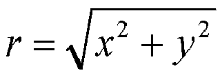


- Because this formula is an optimization problem, laserNum absolute errors

- Then, a column index of the original point cloud data in the planar structure of 2D projection is determined based on the horizontal azimuth information, which specifically includes the following.
(a) The relationship between the horizontal azimuth information of the point cloud and original collection azimuth information is established, and a corresponding relational expression is obtained. - In this embodiment, the relationship between the horizontal azimuth information and original collection azimuth information may be determined from a perspective of algebra based on a collection principle of the laser radar.
- Specifically, the laser radar includes a plurality of laser combinations arranged and distributed along both sides of a central axis. Each laser has a fixed pitch angle and may be considered as a relatively independent collection system. These lasers rotate 360° around the central axis of the laser radar jointly, perform sampling at intervals at a fixed rotation angle during rotation, and return original collection information of a sampling point, namely, original collection distance information r 0 of the sampling point, an index number i(θ 0) of a laser to which the sampling point belongs, and original collection azimuth information ϕ 0, and the information is expressed based on a local cylindrical coordinate system whose corresponding laser is an original point. However, to facilitate subsequent processing of the point cloud, original collection data of the point cloud needs to be converted into the Cartesian coordinate system with a bottom of the laser radar used as a same origin, and a point cloud of the laser radar in a same Cartesian coordinate system, namely, a point cloud finally collected by a device, is formed. The conversion is calibration of the laser radar. As shown in
FIG. 2, FIG. 2 is a schematic diagram of calibration of a laser radar according to an embodiment of the present invention. - A formula for calibrating the laser radar is as follows. Through this formula, original collection information (r 0, i(θ 0), ϕ 0) of a point is converted into Cartesian coordinates (x,y,z). In the original collection information of the point, r 0 is original collection distance information of the point, i(θ 0) is an index number of a laser to which the point belongs, and ϕ 0 is original collection azimuth information of the point:


- Next, it is assumed that


- Horizontal azimuth information ϕ of the point calculated by x and y is as follows:

- Finally, β=ϕ 0-α is substituted to the foregoing equation, to obtain a relational expression between the horizontal azimuth information ϕ and original collection azimuth information ϕ 0 of a point cloud:

- In another embodiment of the present invention, the relationship between the horizontal azimuth information and the original collection azimuth information may also be determined from the perspective of geometry.
- Specifically, the laser radar is calibrated during collection of the point cloud, and original collection information of the laser expressed in a local cylindrical coordinate system is converted into a Cartesian coordinate system with a bottom of the laser radar used as a same original point, and a point cloud of the laser radar in a same Cartesian coordinate system, namely, a point cloud finally collected by the device, is formed, as shown in
FIG. 2 . However, because an azimuth of the point cloud is expressed in the x-y plane of the Cartesian coordinate system,FIG. 3 is further obtained fromFIG. 2 .FIG. 3 is a schematic diagram of calibration of a laser radar in the x-y plane according to embodiment of the present invention. - It can be obtained, through deduction, from
FIG. 3 that

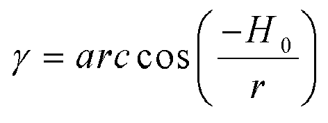

- r is depth information of a point in the point cloud, Ho is the horizontal offset of the laser to which the point belongs, α is a horizontal correction angle of the laser to which the point belongs, and both Ho and α are calibration parameters, namely, regularization parameters, of the laser. It should be noted that, because approximate treatment is used in algebraic derivation, relational expressions obtained in two methods are different in form, but with almost same relation curves.
- (b) The original collection azimuth information of the point cloud is calculated based on the foregoing relational expression.
- Specifically, when a relationship between the horizontal azimuth information and the original collection azimuth information is obtained in an algebraic method, a formula for calculating the original collection azimuth information of the point cloud is as follows:

- When the relationship between the horizontal azimuth information and the original collection azimuth information is obtained in a geometric method, the formula for calculating the original collection azimuth information of the point cloud is as follows:

- (c) A column index of the original point cloud data in the planar structure of 2D projection is calculated based on the original collection azimuth information. A calculation formula is as follows:

- Finally, through this embodiment, a corresponding pixel (i,j) of the current point in the planar structure of 2D projection is obtained, and therefore a mapping relationship between the point cloud and the planar structure of 2D projection is determined. After the foregoing operations are completed for all points in the point cloud, namely, 2D regularized planar projection of the point cloud is completed, as shown in
FIG. 4, FIG. 4 is a schematic diagram of a planar structure of 2D projection of a point cloud according to an embodiment of the present invention. Each point in the point cloud is mapped to a corresponding pixel in the structure. - In this embodiment, a mapping relationship between an original point cloud data and the planar structure of 2D projection is determined through horizontal azimuth information of the point cloud, and a large-scale point cloud may be projected to a 2D regularized plane structure without 2D local search. Therefore, complexity of an algorithm can be reduced, time spent on 2D regularized planar projection of the point cloud can be decreased, and algorithm performance can be improved.
- Furthermore, in this embodiment, a column index of the cloud point projected to a 2D planar structure is determined by a relationship between horizontal azimuth information and original collection azimuth information of the point cloud. Accordingly, the point cloud is regularly corrected in a vertical direction and horizontal direction, and representation of strong correlation of the point cloud on the planar structure of 2D projection is obtained. Therefore, sparsity existing in a 3D representation structure can be prevented, and spatial correlation of the point cloud is better reflected, thereby providing, for application of the point cloud, a representation form used for performing data processing easily.
- Based on the foregoing
Embodiment 1, this embodiment provides an apparatus for the 2D regularized planar projection of the point cloud.FIG. 5 is a schematic structural diagram of an apparatus for 2D regularized planar projection of a point cloud according to an embodiment of the present invention. The apparatus includes: - a
data obtaining module 1, configured to obtain original point cloud data; - an
initializing module 2, configured to initialize a planar structure of 2D projection of a point cloud; - a calculating
module 3, configured to calculate horizontal azimuth information of the point cloud based on the original point cloud data; and - a
mapping module 4, configured to determine a mapping relationship between the original point cloud data and the planar structure of 2D projection based on the horizontal azimuth information, to obtain a planar structure of 2D regularized projection of the point cloud. - The apparatus provided in this embodiment can implement the method for 2D regularized planar projection of a point cloud provided in the foregoing
Embodiment 1. Details are not described herein again. - The foregoing are further detailed descriptions of the present invention with reference to specific preferred implementations, and it cannot be considered that the implementations of the present invention are only limited to these descriptions. A person of ordinary skill in the art to which the present invention belongs may make simple deductions or replacements without departing from the concept of the present invention, all of which shall be considered as falling within the protection scope of the present invention
Claims (8)
- A method for 2D regularized planar projection of a point cloud, comprising:obtaining original point cloud data;initializing a planar structure of 2D projection of the point cloud;calculating horizontal azimuth information of the point cloud based on the original point cloud data; anddetermining a mapping relationship between the original point cloud data and the planar structure of 2D projection based on the horizontal azimuth information, to obtain a planar structure of 2D regularized projection of the point cloud.
- The method for 2D regularized planar projection of the point cloud according to claim 1, wherein a formula for calculating the horizontal azimuth information is as follows:

- The method for 2D regularized planar projection of the point cloud according to claim 1, wherein the determining the mapping relationship between the original point cloud data and the planar structure of 2D projection based on the horizontal azimuth information comprises:determining a row index of the original point cloud data in the planar structure of 2D projection; anddetermining a column index of the original point cloud data in the planar structure of 2D projection based on the horizontal azimuth information.
- The method for 2D regularized planar projection of the point cloud according to claim 3, wherein the determining the column index of the original point cloud data in the planar structure of 2D projection based on the horizontal azimuth information comprises:establishing a relationship between the horizontal azimuth information of the point cloud and original collection azimuth information of the point cloud, and obtaining a corresponding relational expression;calculating the original collection azimuth information of the point cloud based on the relational expression; andcalculating the column index of the original point cloud data in the planar structure of 2D projection based on the original collection azimuth information.
- The method for 2D regularized planar projection of a point cloud according to claim 4, wherein the relational expression between the horizontal azimuth information of the point cloud and the original collection azimuth information of the point cloud is as follows:

- The method for 2D regularized planar projection of a point cloud according to claim 4, wherein the relational expression between the horizontal azimuth information of the point cloud and the original collection azimuth information of the point cloud is as follows:

- The method for 2D regularized planar projection of a point cloud according to claim 4, wherein a formula for calculating the column index of the original point cloud data in the planar structure of 2D projection is as follows:

- An apparatus for 2D regularized planar projection of a point cloud, comprising:a data obtaining module (1), configured to obtain original point cloud data;an initializing module (2), configured to initialize a planar structure of 2D projection of the point cloud;a calculating module (3), configured to calculate horizontal azimuth information of the point cloud based on the original point cloud data; anda mapping module (4), configured to determine a mapping relationship between the original point cloud data and the planar structure of 2D projection based on the horizontal azimuth information, to obtain a planar structure of 2D regularized projection of the point cloud.
Applications Claiming Priority (2)
| Application Number | Priority Date | Filing Date | Title |
|---|---|---|---|
| CN202110578726.3A CN115412721B (en) | 2021-05-26 | 2021-05-26 | A method and device for two-dimensional regularized plane projection of point cloud |
| PCT/CN2022/093676 WO2022247714A1 (en) | 2021-05-26 | 2022-05-18 | Two-dimensional regularized plane projection method and apparatus for point cloud |
Publications (3)
| Publication Number | Publication Date |
|---|---|
| EP4243412A1 true EP4243412A1 (en) | 2023-09-13 |
| EP4243412A4 EP4243412A4 (en) | 2024-08-21 |
| EP4243412B1 EP4243412B1 (en) | 2025-07-09 |
Family
ID=84155985
Family Applications (1)
| Application Number | Title | Priority Date | Filing Date |
|---|---|---|---|
| EP22810441.0A Active EP4243412B1 (en) | 2021-05-26 | 2022-05-18 | Two-dimensional regularized plane projection method and apparatus for point cloud |
Country Status (4)
| Country | Link |
|---|---|
| US (1) | US12430707B2 (en) |
| EP (1) | EP4243412B1 (en) |
| CN (2) | CN118540455A (en) |
| WO (1) | WO2022247714A1 (en) |
Families Citing this family (1)
| Publication number | Priority date | Publication date | Assignee | Title |
|---|---|---|---|---|
| CN118433402A (en) * | 2021-02-08 | 2024-08-02 | 荣耀终端有限公司 | Point cloud encoding and decoding method and device based on two-dimensional regularized plane projection |
Family Cites Families (18)
| Publication number | Priority date | Publication date | Assignee | Title |
|---|---|---|---|---|
| US7439977B2 (en) * | 2003-08-27 | 2008-10-21 | Komarechka Robert G | Method of displaying three-dimensional vector orientations on a two-dimensional surface |
| US7804498B1 (en) * | 2004-09-15 | 2010-09-28 | Lewis N Graham | Visualization and storage algorithms associated with processing point cloud data |
| CN103279989B (en) * | 2013-05-30 | 2016-05-04 | 北京航天控制仪器研究所 | A kind of three-dimensional laser imaging system plane cloud data trigonometric ratio processing method |
| WO2016185637A1 (en) * | 2015-05-20 | 2016-11-24 | 三菱電機株式会社 | Point-cloud-image generation device and display system |
| CN105574905B (en) * | 2015-12-15 | 2018-01-16 | 大连理工大学 | A kind of two dimensional image expression method of three-dimensional laser point cloud data |
| WO2018044958A1 (en) * | 2016-08-29 | 2018-03-08 | Okeeffe James | Laser range finder with smart safety-conscious laser intensity |
| EP3642800B1 (en) | 2017-07-10 | 2025-02-26 | Samsung Electronics Co., Ltd. | Point cloud and mesh compression using image/video codecs |
| US10699444B2 (en) * | 2017-11-22 | 2020-06-30 | Apple Inc | Point cloud occupancy map compression |
| US10935650B2 (en) * | 2017-12-22 | 2021-03-02 | Waymo Llc | Radar based three dimensional point cloud for autonomous vehicles |
| CN109509143A (en) * | 2018-10-31 | 2019-03-22 | 太原理工大学 | A kind of method of three-dimensional point cloud conversion two dimensional image |
| US10346998B1 (en) * | 2019-02-25 | 2019-07-09 | Nurulize, Inc. | Method of merging point clouds that identifies and retains preferred points |
| US11933633B2 (en) * | 2019-02-27 | 2024-03-19 | Aichi Steel Corporation | Point cloud data acquiring method and point cloud data acquiring system |
| CN110428372B (en) * | 2019-07-08 | 2021-12-10 | 佳木斯市奥义智能科技有限公司 | Depth data and 2D laser data fusion method and device and storage medium |
| CN111009011B (en) * | 2019-11-28 | 2023-09-19 | 深圳市镭神智能系统有限公司 | Prediction method, device, system and storage medium for vehicle direction angle |
| US12475595B2 (en) * | 2020-06-18 | 2025-11-18 | Commonwealth Scientific And Industrial Research Organisation | Navigation of an underground mining machine |
| CN112150595A (en) * | 2020-09-21 | 2020-12-29 | 广东博智林机器人有限公司 | Point cloud data processing method, device, equipment and medium |
| DE102020130884A1 (en) * | 2020-11-23 | 2022-05-25 | Valeo Schalter Und Sensoren Gmbh | Active sensor system and object recognition |
| JP7678138B2 (en) * | 2021-04-21 | 2025-05-15 | エルジー エレクトロニクス インコーポレイティド | Point cloud data transmitting device, point cloud data transmitting method, point cloud data receiving device, and point cloud data receiving method |
-
2021
- 2021-05-26 CN CN202410622537.5A patent/CN118540455A/en active Pending
- 2021-05-26 CN CN202110578726.3A patent/CN115412721B/en active Active
-
2022
- 2022-05-18 WO PCT/CN2022/093676 patent/WO2022247714A1/en not_active Ceased
- 2022-05-18 EP EP22810441.0A patent/EP4243412B1/en active Active
- 2022-05-18 US US18/266,374 patent/US12430707B2/en active Active
Also Published As
| Publication number | Publication date |
|---|---|
| WO2022247714A1 (en) | 2022-12-01 |
| EP4243412B1 (en) | 2025-07-09 |
| CN118540455A (en) | 2024-08-23 |
| US12430707B2 (en) | 2025-09-30 |
| EP4243412A4 (en) | 2024-08-21 |
| CN115412721A (en) | 2022-11-29 |
| US20240112300A1 (en) | 2024-04-04 |
| CN115412721B (en) | 2024-05-28 |
Similar Documents
| Publication | Publication Date | Title |
|---|---|---|
| US10613227B2 (en) | Method and apparatus for positioning vehicle | |
| US20210319588A1 (en) | Method and Apparatus for Calibrating External Parameters of Image Acquisition Device, Device and Storage Medium | |
| CN110441758B (en) | On-orbit geometric calibration method for satellite-borne linear array multi-beam altimetry laser radar | |
| EP4109131B1 (en) | Laser radar parameter calibration method and apparatus | |
| US8300048B2 (en) | Three-dimensional shape data recording/display method and device, and three-dimensional shape measuring method and device | |
| US8116558B2 (en) | Three-dimensional shape data position matching method and device | |
| CN111123242B (en) | Combined calibration method based on laser radar and camera and computer readable storage medium | |
| CN114049401B (en) | Binocular camera calibration method, device, equipment and medium | |
| CN111913169B (en) | Correction method, equipment and storage medium of lidar internal reference and point cloud data | |
| CN104615880B (en) | Rapid ICP (inductively coupled plasma) method for point cloud matching of three-dimensional laser radar | |
| US12499579B2 (en) | Method and apparatus for registering devices of autonomous vehicle based on trajectory alignment | |
| CN115081240B (en) | A point cloud data processing method to improve the authenticity of simulated lidar data | |
| CN103065036A (en) | Systems and methods for combining a priori data with sensor data | |
| US20250069183A1 (en) | Method and apparatus of processing image, interactive device, electronic device, and storage medium | |
| CN115100287B (en) | External parameter calibration method and robot | |
| US12430707B2 (en) | Method and apparatus for 2D regularized planar projection of point cloud | |
| CN115810028A (en) | Multi-target tracking method based on multi-modal data | |
| Song et al. | Flexible line-scan camera calibration method using a coded eight trigrams pattern | |
| CN114792333B (en) | Light bar matching method, device, system and storage medium | |
| CN114255277B (en) | Data labeling method, device and electronic equipment | |
| CN119165452A (en) | A joint calibration method and device for camera and 4D millimeter wave radar | |
| Zhou et al. | Estimation of the plot-level forest parameters from terrestrial laser scanning data | |
| Gong et al. | Scene-aware online calibration of LiDAR and cameras for driving systems | |
| CN113280789B (en) | Method for taking laser height measurement points of relief area as image elevation control points | |
| US20220373328A1 (en) | Processing device of depth information |
Legal Events
| Date | Code | Title | Description |
|---|---|---|---|
| STAA | Information on the status of an ep patent application or granted ep patent |
Free format text: STATUS: THE INTERNATIONAL PUBLICATION HAS BEEN MADE |
|
| PUAI | Public reference made under article 153(3) epc to a published international application that has entered the european phase |
Free format text: ORIGINAL CODE: 0009012 |
|
| STAA | Information on the status of an ep patent application or granted ep patent |
Free format text: STATUS: REQUEST FOR EXAMINATION WAS MADE |
|
| 17P | Request for examination filed |
Effective date: 20230608 |
|
| AK | Designated contracting states |
Kind code of ref document: A1 Designated state(s): AL AT BE BG CH CY CZ DE DK EE ES FI FR GB GR HR HU IE IS IT LI LT LU LV MC MK MT NL NO PL PT RO RS SE SI SK SM TR |
|
| A4 | Supplementary search report drawn up and despatched |
Effective date: 20240719 |
|
| RIC1 | Information provided on ipc code assigned before grant |
Ipc: G06T 15/10 20110101ALI20240715BHEP Ipc: G01S 17/86 20200101ALI20240715BHEP Ipc: G01S 17/42 20060101ALI20240715BHEP Ipc: G01S 17/89 20200101ALI20240715BHEP Ipc: H04N 13/327 20180101AFI20240715BHEP |
|
| DAV | Request for validation of the european patent (deleted) | ||
| DAX | Request for extension of the european patent (deleted) | ||
| GRAP | Despatch of communication of intention to grant a patent |
Free format text: ORIGINAL CODE: EPIDOSNIGR1 |
|
| STAA | Information on the status of an ep patent application or granted ep patent |
Free format text: STATUS: GRANT OF PATENT IS INTENDED |
|
| INTG | Intention to grant announced |
Effective date: 20250124 |
|
| GRAS | Grant fee paid |
Free format text: ORIGINAL CODE: EPIDOSNIGR3 |
|
| GRAA | (expected) grant |
Free format text: ORIGINAL CODE: 0009210 |
|
| STAA | Information on the status of an ep patent application or granted ep patent |
Free format text: STATUS: THE PATENT HAS BEEN GRANTED |
|
| AK | Designated contracting states |
Kind code of ref document: B1 Designated state(s): AL AT BE BG CH CY CZ DE DK EE ES FI FR GB GR HR HU IE IS IT LI LT LU LV MC MK MT NL NO PL PT RO RS SE SI SK SM TR |
|
| REG | Reference to a national code |
Ref country code: GB Ref legal event code: FG4D |
|
| REG | Reference to a national code |
Ref country code: CH Ref legal event code: EP |
|
| REG | Reference to a national code |
Ref country code: IE Ref legal event code: FG4D |
|
| REG | Reference to a national code |
Ref country code: DE Ref legal event code: R096 Ref document number: 602022017451 Country of ref document: DE |
|
| REG | Reference to a national code |
Ref country code: NL Ref legal event code: FP |
|
| PG25 | Lapsed in a contracting state [announced via postgrant information from national office to epo] |
Ref country code: PT Free format text: LAPSE BECAUSE OF FAILURE TO SUBMIT A TRANSLATION OF THE DESCRIPTION OR TO PAY THE FEE WITHIN THE PRESCRIBED TIME-LIMIT Effective date: 20251110 |
|
| REG | Reference to a national code |
Ref country code: AT Ref legal event code: MK05 Ref document number: 1812964 Country of ref document: AT Kind code of ref document: T Effective date: 20250709 |
|
| PG25 | Lapsed in a contracting state [announced via postgrant information from national office to epo] |
Ref country code: IS Free format text: LAPSE BECAUSE OF FAILURE TO SUBMIT A TRANSLATION OF THE DESCRIPTION OR TO PAY THE FEE WITHIN THE PRESCRIBED TIME-LIMIT Effective date: 20251109 |
|
| PG25 | Lapsed in a contracting state [announced via postgrant information from national office to epo] |
Ref country code: NO Free format text: LAPSE BECAUSE OF FAILURE TO SUBMIT A TRANSLATION OF THE DESCRIPTION OR TO PAY THE FEE WITHIN THE PRESCRIBED TIME-LIMIT Effective date: 20251009 |
|
| REG | Reference to a national code |
Ref country code: LT Ref legal event code: MG9D |
|
| PG25 | Lapsed in a contracting state [announced via postgrant information from national office to epo] |
Ref country code: AT Free format text: LAPSE BECAUSE OF FAILURE TO SUBMIT A TRANSLATION OF THE DESCRIPTION OR TO PAY THE FEE WITHIN THE PRESCRIBED TIME-LIMIT Effective date: 20250709 |
|
| PG25 | Lapsed in a contracting state [announced via postgrant information from national office to epo] |
Ref country code: FI Free format text: LAPSE BECAUSE OF FAILURE TO SUBMIT A TRANSLATION OF THE DESCRIPTION OR TO PAY THE FEE WITHIN THE PRESCRIBED TIME-LIMIT Effective date: 20250709 |
|
| PG25 | Lapsed in a contracting state [announced via postgrant information from national office to epo] |
Ref country code: HR Free format text: LAPSE BECAUSE OF FAILURE TO SUBMIT A TRANSLATION OF THE DESCRIPTION OR TO PAY THE FEE WITHIN THE PRESCRIBED TIME-LIMIT Effective date: 20250709 |
|
| PG25 | Lapsed in a contracting state [announced via postgrant information from national office to epo] |
Ref country code: GR Free format text: LAPSE BECAUSE OF FAILURE TO SUBMIT A TRANSLATION OF THE DESCRIPTION OR TO PAY THE FEE WITHIN THE PRESCRIBED TIME-LIMIT Effective date: 20251010 |
|
| PG25 | Lapsed in a contracting state [announced via postgrant information from national office to epo] |
Ref country code: SE Free format text: LAPSE BECAUSE OF FAILURE TO SUBMIT A TRANSLATION OF THE DESCRIPTION OR TO PAY THE FEE WITHIN THE PRESCRIBED TIME-LIMIT Effective date: 20250709 |
|
| PG25 | Lapsed in a contracting state [announced via postgrant information from national office to epo] |
Ref country code: LV Free format text: LAPSE BECAUSE OF FAILURE TO SUBMIT A TRANSLATION OF THE DESCRIPTION OR TO PAY THE FEE WITHIN THE PRESCRIBED TIME-LIMIT Effective date: 20250709 |
|
| PG25 | Lapsed in a contracting state [announced via postgrant information from national office to epo] |
Ref country code: BG Free format text: LAPSE BECAUSE OF FAILURE TO SUBMIT A TRANSLATION OF THE DESCRIPTION OR TO PAY THE FEE WITHIN THE PRESCRIBED TIME-LIMIT Effective date: 20250709 Ref country code: PL Free format text: LAPSE BECAUSE OF FAILURE TO SUBMIT A TRANSLATION OF THE DESCRIPTION OR TO PAY THE FEE WITHIN THE PRESCRIBED TIME-LIMIT Effective date: 20250709 |
|
| PG25 | Lapsed in a contracting state [announced via postgrant information from national office to epo] |
Ref country code: RS Free format text: LAPSE BECAUSE OF FAILURE TO SUBMIT A TRANSLATION OF THE DESCRIPTION OR TO PAY THE FEE WITHIN THE PRESCRIBED TIME-LIMIT Effective date: 20251009 |
|
| PG25 | Lapsed in a contracting state [announced via postgrant information from national office to epo] |
Ref country code: ES Free format text: LAPSE BECAUSE OF FAILURE TO SUBMIT A TRANSLATION OF THE DESCRIPTION OR TO PAY THE FEE WITHIN THE PRESCRIBED TIME-LIMIT Effective date: 20250709 |
|
| PG25 | Lapsed in a contracting state [announced via postgrant information from national office to epo] |
Ref country code: SM Free format text: LAPSE BECAUSE OF FAILURE TO SUBMIT A TRANSLATION OF THE DESCRIPTION OR TO PAY THE FEE WITHIN THE PRESCRIBED TIME-LIMIT Effective date: 20250709 |
|
| PGFP | Annual fee paid to national office [announced via postgrant information from national office to epo] |
Ref country code: GB Payment date: 20260324 Year of fee payment: 5 |
|
| PG25 | Lapsed in a contracting state [announced via postgrant information from national office to epo] |
Ref country code: DK Free format text: LAPSE BECAUSE OF FAILURE TO SUBMIT A TRANSLATION OF THE DESCRIPTION OR TO PAY THE FEE WITHIN THE PRESCRIBED TIME-LIMIT Effective date: 20250709 |
|
| PG25 | Lapsed in a contracting state [announced via postgrant information from national office to epo] |
Ref country code: IT Free format text: LAPSE BECAUSE OF FAILURE TO SUBMIT A TRANSLATION OF THE DESCRIPTION OR TO PAY THE FEE WITHIN THE PRESCRIBED TIME-LIMIT Effective date: 20250709 |
|
| PG25 | Lapsed in a contracting state [announced via postgrant information from national office to epo] |
Ref country code: CZ Free format text: LAPSE BECAUSE OF FAILURE TO SUBMIT A TRANSLATION OF THE DESCRIPTION OR TO PAY THE FEE WITHIN THE PRESCRIBED TIME-LIMIT Effective date: 20250709 |
|
| PG25 | Lapsed in a contracting state [announced via postgrant information from national office to epo] |
Ref country code: EE Free format text: LAPSE BECAUSE OF FAILURE TO SUBMIT A TRANSLATION OF THE DESCRIPTION OR TO PAY THE FEE WITHIN THE PRESCRIBED TIME-LIMIT Effective date: 20250709 Ref country code: SK Free format text: LAPSE BECAUSE OF FAILURE TO SUBMIT A TRANSLATION OF THE DESCRIPTION OR TO PAY THE FEE WITHIN THE PRESCRIBED TIME-LIMIT Effective date: 20250709 |
|
| PLBE | No opposition filed within time limit |
Free format text: ORIGINAL CODE: 0009261 |
|
| STAA | Information on the status of an ep patent application or granted ep patent |
Free format text: STATUS: NO OPPOSITION FILED WITHIN TIME LIMIT |