EP4243384A1 - Hinge, display module and electronic device - Google Patents
Hinge, display module and electronic device Download PDFInfo
- Publication number
- EP4243384A1 EP4243384A1 EP22187592.5A EP22187592A EP4243384A1 EP 4243384 A1 EP4243384 A1 EP 4243384A1 EP 22187592 A EP22187592 A EP 22187592A EP 4243384 A1 EP4243384 A1 EP 4243384A1
- Authority
- EP
- European Patent Office
- Prior art keywords
- rod
- mounting position
- pivotably coupled
- base
- connection member
- Prior art date
- Legal status (The legal status is an assumption and is not a legal conclusion. Google has not performed a legal analysis and makes no representation as to the accuracy of the status listed.)
- Granted
Links
Images


Classifications
-
- F—MECHANICAL ENGINEERING; LIGHTING; HEATING; WEAPONS; BLASTING
- F16—ENGINEERING ELEMENTS AND UNITS; GENERAL MEASURES FOR PRODUCING AND MAINTAINING EFFECTIVE FUNCTIONING OF MACHINES OR INSTALLATIONS; THERMAL INSULATION IN GENERAL
- F16C—SHAFTS; FLEXIBLE SHAFTS; ELEMENTS OR CRANKSHAFT MECHANISMS; ROTARY BODIES OTHER THAN GEARING ELEMENTS; BEARINGS
- F16C11/00—Pivots; Pivotal connections
- F16C11/04—Pivotal connections
-
- G—PHYSICS
- G06—COMPUTING OR CALCULATING; COUNTING
- G06F—ELECTRIC DIGITAL DATA PROCESSING
- G06F1/00—Details not covered by groups G06F3/00 - G06F13/00 and G06F21/00
- G06F1/16—Constructional details or arrangements
- G06F1/1613—Constructional details or arrangements for portable computers
- G06F1/1633—Constructional details or arrangements of portable computers not specific to the type of enclosures covered by groups G06F1/1615 - G06F1/1626
- G06F1/1637—Details related to the display arrangement, including those related to the mounting of the display in the housing
- G06F1/1652—Details related to the display arrangement, including those related to the mounting of the display in the housing the display being flexible, e.g. mimicking a sheet of paper, or rollable
-
- G—PHYSICS
- G06—COMPUTING OR CALCULATING; COUNTING
- G06F—ELECTRIC DIGITAL DATA PROCESSING
- G06F1/00—Details not covered by groups G06F3/00 - G06F13/00 and G06F21/00
- G06F1/16—Constructional details or arrangements
- G06F1/1613—Constructional details or arrangements for portable computers
- G06F1/1633—Constructional details or arrangements of portable computers not specific to the type of enclosures covered by groups G06F1/1615 - G06F1/1626
- G06F1/1675—Miscellaneous details related to the relative movement between the different enclosures or enclosure parts
- G06F1/1681—Details related solely to hinges
-
- H—ELECTRICITY
- H04—ELECTRIC COMMUNICATION TECHNIQUE
- H04M—TELEPHONIC COMMUNICATION
- H04M1/00—Substation equipment, e.g. for use by subscribers
- H04M1/02—Constructional features of telephone sets
- H04M1/0202—Portable telephone sets, e.g. cordless phones, mobile phones or bar type handsets
- H04M1/0206—Portable telephones comprising a plurality of mechanically joined movable body parts, e.g. hinged housings
- H04M1/0208—Portable telephones comprising a plurality of mechanically joined movable body parts, e.g. hinged housings characterized by the relative motions of the body parts
- H04M1/0214—Foldable telephones, i.e. with body parts pivoting to an open position around an axis parallel to the plane they define in closed position
- H04M1/0216—Foldable in one direction, i.e. using a one degree of freedom hinge
- H04M1/022—The hinge comprising two parallel pivoting axes
-
- H—ELECTRICITY
- H05—ELECTRIC TECHNIQUES NOT OTHERWISE PROVIDED FOR
- H05K—PRINTED CIRCUITS; CASINGS OR CONSTRUCTIONAL DETAILS OF ELECTRIC APPARATUS; MANUFACTURE OF ASSEMBLAGES OF ELECTRICAL COMPONENTS
- H05K5/00—Casings, cabinets or drawers for electric apparatus
- H05K5/0017—Casings, cabinets or drawers for electric apparatus with operator interface units
- H05K5/0018—Casings, cabinets or drawers for electric apparatus with operator interface units having an electronic display
-
- H—ELECTRICITY
- H05—ELECTRIC TECHNIQUES NOT OTHERWISE PROVIDED FOR
- H05K—PRINTED CIRCUITS; CASINGS OR CONSTRUCTIONAL DETAILS OF ELECTRIC APPARATUS; MANUFACTURE OF ASSEMBLAGES OF ELECTRICAL COMPONENTS
- H05K5/00—Casings, cabinets or drawers for electric apparatus
- H05K5/02—Details
- H05K5/0217—Mechanical details of casings
- H05K5/0226—Hinges
-
- E—FIXED CONSTRUCTIONS
- E05—LOCKS; KEYS; WINDOW OR DOOR FITTINGS; SAFES
- E05D—HINGES OR SUSPENSION DEVICES FOR DOORS, WINDOWS OR WINGS
- E05D3/00—Hinges with pins
- E05D3/06—Hinges with pins with two or more pins
- E05D3/12—Hinges with pins with two or more pins with two parallel pins and one arm
- E05D3/122—Gear hinges
-
- E—FIXED CONSTRUCTIONS
- E05—LOCKS; KEYS; WINDOW OR DOOR FITTINGS; SAFES
- E05D—HINGES OR SUSPENSION DEVICES FOR DOORS, WINDOWS OR WINGS
- E05D3/00—Hinges with pins
- E05D3/06—Hinges with pins with two or more pins
- E05D3/18—Hinges with pins with two or more pins with sliding pins or guides
-
- E—FIXED CONSTRUCTIONS
- E05—LOCKS; KEYS; WINDOW OR DOOR FITTINGS; SAFES
- E05Y—INDEXING SCHEME ASSOCIATED WITH SUBCLASSES E05D AND E05F, RELATING TO CONSTRUCTION ELEMENTS, ELECTRIC CONTROL, POWER SUPPLY, POWER SIGNAL OR TRANSMISSION, USER INTERFACES, MOUNTING OR COUPLING, DETAILS, ACCESSORIES, AUXILIARY OPERATIONS NOT OTHERWISE PROVIDED FOR, APPLICATION THEREOF
- E05Y2999/00—Subject-matter not otherwise provided for in this subclass
-
- H—ELECTRICITY
- H04—ELECTRIC COMMUNICATION TECHNIQUE
- H04M—TELEPHONIC COMMUNICATION
- H04M1/00—Substation equipment, e.g. for use by subscribers
- H04M1/02—Constructional features of telephone sets
- H04M1/0202—Portable telephone sets, e.g. cordless phones, mobile phones or bar type handsets
- H04M1/026—Details of the structure or mounting of specific components
- H04M1/0266—Details of the structure or mounting of specific components for a display module assembly
- H04M1/0268—Details of the structure or mounting of specific components for a display module assembly including a flexible display panel
Definitions
- the present invention relates to a field of electronic devices, and more particularly, to a hinge, a display module and an electronic device.
- foldable electronic devices enjoy both the portability of ordinary electronic devices, and the large visual angle of large screen displays after being unfolded.
- Foldable electronic devices have become an important trend in the development of mobile terminals and an important area of competition among major terminal manufacturers.
- hinge structures are very important, and the performance of the hinge structures will directly affect the function and experience of products.
- the screen is not flat when unfolded, which degrades user experience.
- the present invention aims to solve at least one of the technical problems in the related art to a certain extent.
- embodiments of the present invention propose a hinge that has a better support effect on a screen and a high degree of fitting with the screen.
- Embodiments of the present invention further propose a display module.
- Embodiments of the present invention further propose an electronic device.
- a hinge includes a base extending along a first direction; and a rotating component including a floating plate and a rotating assembly.
- a first end of the rotating assembly is pivotably coupled to the base, and a second end of the rotating assembly is pivotably coupled to a first mounting position and a second mounting position on the floating plate, the first mounting position and the second mounting position being spaced apart along a second direction that is orthogonal to the first direction.
- the rotating assembly is slidable relative to the second mounting position along the second direction.
- a display module or an electronic device using the hinge can better support a screen by the floating plate when folded or unfolded, and the floating plate has a higher fit with the screen, resulting in higher flatness.
- the rotating assembly includes a first rod, a second rod and a connection member; a first end of the first rod is pivotably coupled to the base; the connection member is slidable relative to the first rod, and the connection member is pivotably coupled to the first mounting position; a first end of the second rod is pivotably coupled to the base, and a second end of the second rod is pivotably coupled to the second mounting position and is slidable relative to the second mounting position.
- the rotating assembly further includes a third rod, a first end of the third rod being pivotably coupled to the connection member, and a second end of the third rod being pivotably coupled to the second rod.
- a first notch is in the connection member, a first pivot hole is on a side of the first notch along the first direction, and a second pivot hole is in the first end of the third rod; and a first pivot member is inserted in and passes through the first pivot hole and the second pivot hole, and the first notch is pivotably coupled to the first end of the third rod.
- the first pivot hole is in communication with a side of the connection member along the first direction.
- the rotating assembly further includes a fourth rod, a first end of the fourth rod being pivotably coupled to the first rod, and a second end of the fourth rod being pivotably coupled to the second rod.
- the rotating assembly further includes a fourth rod, a first end of the fourth rod being pivotably coupled to the first rod, and a second end of the fourth rod being pivotably coupled to the second end of the third rod; a pivot axis of the fourth rod relative to the third rod and a pivot axis of the third rod relative to the second rod are on a common axis and parallel to the first direction.
- the first rod, the fourth rod, the third rod and the second rod are arranged side by side along the first direction.
- a first slide groove is in one of the connection member and the first mounting position, a first slide rail is on the other of the connection member and the first mounting position, and the first slide rail is fitted with the first slide groove; the first slide groove extends along a first arc line, an axis of the first arc line is in a same direction as the first direction, and the first slide rail is slidably fitted with the first slide groove along the first arc line, allowing the connection member to rotate relative to the floating plate.
- a second slide groove is in one of the connection member and the first rod
- a second slide rail is on the other of the connection member and the first rod
- the second slide rail is slidably fitted with the second slide groove in a direction orthogonal to the first direction
- a third slide hole is in one of the second rod and the second mounting position
- a third slide rail is on the other of the second rod and the second mounting position
- the third slide rail is pivotably coupled to the third slide hole and slidably fitted with the third slide hole along the second direction.
- the third slide rail is on a side of the second rod adjacent to the floating plate and extends along the first direction, the third slide hole is formed in the second mounting position, and an axial direction of the third slide hole is parallel to the first direction.
- an arc-shaped recess is in one of the second rod and the base, an arc-shaped shaft portion is on the other of the second rod and the base, and the arc-shaped recess is pivotably coupled to the arc-shaped shaft portion.
- the rotating assembly further includes a gear transmission pair having a first meshing tooth, the first rod has a second meshing tooth, and the first meshing tooth meshes with the second meshing tooth to drive the first rod to rotate relative to the base.
- the gear transmission pair includes a gear shaft, the first meshing tooth is on the gear shaft, and the gear shaft is pivotably coupled to the base.
- the base includes a second notch, a third pivot hole and a fourth pivot hole are on a side of the second notch along the first direction, the first end of the first rod is pivotably fitted in the third pivot hole, and an end of the gear shaft is pivotably fitted in the fourth pivot hole.
- two first mounting portions are on the base and spaced apart along the first direction, the second notch is defined between the two first mounting portions, and the third pivot hole and the fourth pivot hole are in the first mounting portions.
- two groups of the rotating components are pivotably coupled to two sides of the base correspondingly.
- the rotating assembly further includes a gear shaft, and the gear shaft is pivotably coupled to the base.
- the gear shaft has a first meshing tooth
- the first rod has a second meshing tooth
- the first meshing tooth meshes with the second meshing tooth.
- two groups of rotating components are provided, the rotating assembly of each group of rotating components includes the gear shaft, and two gear shafts are on two sides of the base and are rotatable relative to the base.
- the gear shaft has a first meshing tooth
- the first rod has a second meshing tooth
- the first meshing tooth meshes with the second meshing tooth
- first meshing teeth of the two gear shafts mesh with each other.
- a display module includes a screen and a hinge that is the hinge described in any one of the above embodiments, in which the floating plate supports the screen.
- the screen may be supported by the floating plate. Since the second end of the rotating assembly is pivotably coupled to the first mounting position and the second mounting position, and the rotating assembly is slidable relative to the second mounting position in the second direction, the screen may be better supported by the floating plate when the display module is folded or unfolded, so that the floating plate has a higher fit with the screen, resulting in higher flatness.
- An electronic device includes the hinge described in any one of the above embodiments or the display module described in the above embodiments.
- the screen may be supported by the floating plate. Since the second end of the rotating assembly is pivotably coupled to the first mounting position and the second mounting position, and the rotating assembly is slidable relative to the second mounting position in the second direction, the screen may be better supported by the floating plate when the electronic device is folded or unfolded, so that the floating plate has a higher fit with the screen, resulting in higher flatness.
- a hinge, a display module, and an electronic device according to embodiments of the present invention will be described below with reference to FIGS. 1 to 4 .
- the hinge includes a base 1 and a rotating component 2, the base 1 extends along a first direction, and the rotating component 2 includes a floating plate 22 and a rotating assembly 21.
- a first mounting position 221 and a second mounting position 222 are on the floating plate 22 and spaced apart along a second direction orthogonal to the first direction.
- a first end of the rotating assembly 21 is pivotably coupled to the base 1, and a second end of the rotating assembly 21 is pivotably coupled to the first mounting position 221 and the second mounting position 222.
- the rotating assembly 21 is slidable relative to the second mounting position 222 along the second direction.
- the first direction is an A direction in FIG. 2 , i.e., a length direction of the base 1
- the second direction is a B direction in FIG. 2 , i.e., a width direction of the floating plate 22.
- the floating plate 22 rotates about an axial direction of the first direction, and the second direction may always be orthogonal to the first direction.
- the first direction may be the length direction or a width direction of the base 1.
- the situation shown in FIG. 2 is merely an example and does not represent a limitation, and the embodiments of the present invention are not limited to the situation shown in FIG. 2 .
- the second end of the rotating assembly 21 is pivotably coupled to the first mounting position 221 and the second mounting position 222, and the rotating assembly 21 is slidable relative to the second mounting position 222 along the second direction, so that the display module or the electronic device using the hinge can better support a screen by the floating plate 22 when folded or unfolded, resulting in a better fit between the floating plate 22 and the screen and achieving higher flatness.
- the second mounting position 222 is closer to the base 1 than the first mounting position 221.
- the rotating assembly 21 rotates about the first direction relative to the base 1, the rotating assembly 21 may rotate relative to the first mounting position 221 of the floating plate 22, and the rotating assembly 21 may not only rotate relative to the second mounting position 222 of the floating plate 22, but also slide relative to the second mounting position 222 along the second direction.
- the rotation of the floating plate 22 can better adapt to a natural bending shape of the screen.
- the floating plate 22 may fully fit with the screen, and the hinge has a better fit with the screen, leading to higher flatness.
- a contour of the folded hinge exhibits a substantially teardrop shape, which can effectively support and protect the screen.
- the rotating assembly 21 includes a first rod 211, a second rod 212 and a connection member 215.
- the first rod 211 and the second rod 212 are arranged side by side on the base 1 and are rotatable relative to the base 1.
- the connection member 215 is slidable relative to the first rod 211. It can be understood that a pivot axis around which a first end of the first rod 211 pivots relative to the base 1 is in the same direction as the first direction; a width of the connection member 215 extends substantially along the second direction; and the first rod 211 slides relative to the second rod 212 along a width direction of the connection member 215.
- connection member 215 is pivotably coupled to the first mounting position 221, so that the connection member 215 is rotatable relative to the floating plate 22.
- a first end of the second rod 212 is pivotably coupled to the base 1, and a second end of the second rod 212 is pivotably coupled to the second mounting position 222 and is slidable relative to the second mounting position 222.
- the hinge since the rotating assembly 21 is configured with the above structure, the hinge can achieve a simple structure, a reasonable design, a small number of parts, and lower production and manufacturing costs.
- the rotating assembly 21 further includes a third rod 213, a first end of the third rod 213 is pivotably coupled to the connection member 215, and a second end of the third rod 213 is pivotably coupled to the second rod 212.
- the arrangement of the third rod 213 a better linkage effect during the rotation of the second rod 212 and the connection member 215.
- a rotation trajectory of the floating plate 22 fits better with a bending trajectory of the screen when the hinge is folded or unfolded, improving a folding effect of the screen.
- the connection member 215 includes a first notch 2153, a first pivot hole 2154 is on a side of the first notch 2153 along the first direction, and a second pivot hole 2131 is in the first end of the third rod 213.
- the first end of the third rod 213 is in the first notch 2153.
- a first pivot member (not shown) is arranged in and passes through the first pivot hole 2154 and the second pivot hole 2131, so that the first end of the third rod 213 is pivotably coupled in the first notch 2153.
- the first pivot member may be a pin shaft.
- the first pivot hole 2154 runs through two opposite sides of the first notch 2153.
- the first pivot member is detachably mounted in the first pivot hole 2154 and pivotably coupled to the second pivot hole 2131.
- the first end of the third rod 213 is fitted in the first notch 2153, resulting in a more compact structure and a reasonable layout design of the hinge structure.
- a first avoidance groove 2155 is at a position adjacent to the first notch 2153 and is configured to avoid the second mounting position 222 and the second rod 212.
- the arrangement of the first avoidance groove 2155 can avoid interference during the rotation of the floating plate 22 and the second rod 212 relative to the connection member 215, so that the hinge can rotate more smoothly and flexibly, and the hinge can achieve a more compact structure and a reasonable layout design.
- the first pivot hole 2154 is in communication with a side of the connection member 215 along the first direction. It can be understood that when the first pivot member is mounted, an end of the first pivot member may be inserted into the first pivot hole 2154 from the side of the connection member 215, which facilitates the assembly of the hinge and facilitates the processing and manufacturing.
- the rotating assembly 21 further includes a fourth rod 214, a first end of the fourth rod 214 is pivotably coupled to the first rod 211, and a second end of the fourth rod 214 is pivotably coupled to the second rod 212.
- the arrangement of the fourth rod 214 allows a better linkage effect during the rotation of the first rod 211 and the second rod 212.
- the rotation trajectory of the floating plate 22 fits better with the bending trajectory of the screen when the hinge is folded or unfolded, improving the folding effect of the screen.
- a pivot axis of the fourth rod 214 relative to the third rod 213 and a pivot axis of the third rod 213 relative to the second rod 212 are on a common axis and parallel to the first direction.
- the second rod 212, the third rod 213 and the fourth rod 214 may be coupled in series through a common pin shaft, to enable the second rod 212, the third rod 213 and the fourth rod 214 to rotate around the same axis, so that the linkage effect of the hinge can be further improved.
- a mounting space between the first rod 211 and the second rod 212 can be effectively used to make a thickness of the hinge small, which is conducive to a lightweight and thin design of the whole device, thus improving user experience.
- the first rod 211, the fourth rod 214, the third rod 213 and the second rod 212 are arranged side by side in the first direction. It can be understood that the first rod 211, the fourth rod 214, the third rod 213 and the second rod 212 are arranged sequentially in the first direction. Alternatively, the third rod 213 may be on a side of the first rod 211 or the second rod 212 or may be between the first rod 211 and the second rod 212. In the hinge according to the embodiments of the present invention, relative positions of the first rod 211, the second rod 212, the third rod 213 and the fourth rod 214 may be adjusted according to actual needs, so that the hinge has a wider application range and a better support effect.
- a first slide groove 2151 is in one of the connection member 215 and the first mounting position 221, and a first slide rail 2211 is on the other of the connection member 215 and the first mounting position 221.
- the first slide groove 2151 is in the connection member 215, and the first slide rail 2211 is on the first mounting position 221.
- the first slide rail 2211 is slidably fitted with the first slide groove 2151, the first slide groove 2151 extends along a first arc line, and an axis of the first arc line is in the same direction as the first direction.
- the first slide rail 2211 is slidably fitted with the first slide groove 2151 along the first arc line, so that the connection member 215 is rotatable relative to the floating plate 22. It can be understood that when the hinge is folded, the connection member 215 rotates relative to the floating plate 22, so that the first slide rail 2211 slides into the first slide groove 2151 along the first arc line. When the hinge is unfolded, the connection member 215 rotates relative to the floating plate 22, so that part of the first slide rail 2211 gradually slides out of the first slide groove 2151 along the first arc line. As a result, the structure of connection between the connection member 215 and the floating plate 22 is reasonably designed and the reliability of connection is higher. In addition, the arrangement of the first slide rail 2211 and the first slide groove 2151 eliminates the need for any front opening in the floating plate 22, and improves the support effect of the floating plate 22 on the screen.
- a second slide groove 2152 is in one of the connection member 215 and the first rod 211, and a second slide rail 2111 is on the other of the connection member 215 and the first rod 211.
- the second slide groove 2152 is in the connection member 215, and the second slide rail 2111 is on the first rod 211.
- the width of the connection member 215 generally extends along the second direction
- the second slide rail 2111 extends along the width direction of the connection member 215 and is slidably fitted with the second slide groove 2152.
- the arrangement of the second slide rail 2111 and the second slide groove 2152 makes the structure of connection between the connection member 215 and the first rod 211 more stable, and the structural design is simple, facilitating the processing and manufacturing and reducing production costs.
- a third slide hole 2221 is in one of the second rod 212 and the second mounting position 222, and a third slide rail 2121 is on the other of the second rod 212 and the second mounting position 222.
- the third slide rail 2121 is on a side of the second rod 212 adjacent to the floating plate 22 and extends along the first direction.
- the third slide hole 2221 is formed in the second mounting position 222.
- An axial direction of the third slide hole 2221 is parallel to the first direction.
- the third slide rail 2121 is in a clearance fit with the third slide hole 2221, so that the third slide rail 2121 is slidable relative to the third slide hole 2221 along the second direction.
- the arrangement of the third slide rail 2121 and the third slide hole 2221 makes the structure of connection between the second rod 212 and the floating plate 22 more stable, and the structural design is simple, facilitating the processing and manufacturing and reducing production costs.
- the floating plate 22 includes a floating plate body 223, the first slide rail 2211, and a protrusion 224.
- the first slide rail 2211 is on a side of the floating plate body 223 facing away from the base 1, and the protrusion 224 is on a side of the floating plate body 223 adjacent to the base 1.
- the first slide rail 2211 constitutes the first mounting position 221
- the third slide hole 2221 is in the protrusion 224
- the third slide hole 2221 constitutes the second mounting position 222.
- the floating plate body 223 includes a second avoidance groove 2231 arranged side by side with the protrusion 224.
- the second avoidance groove 2231 is configured to avoid the second rod 212, the third rod 213 and the fourth rod 214. It can be understood that the interference during the rotation of the second rod 212, the third rod 213 and the fourth rod 214 relative to the floating plate 22 can be avoided by the second avoidance groove 2231, so that the hinge can rotate more smoothly and flexibly and achieve a more compact structure and a reasonable layout design.
- the rotating assembly 21 further includes a gear transmission pair having a first meshing tooth 231, the first rod 211 has a second meshing tooth 2112, and the first meshing tooth 231 meshes with the second meshing tooth 2112 to drive the first rod 211 to rotate relative to the base 1. Since the hinge may drive the first rod 211 to swing by the gear transmission pair, the rotation of the rotating assembly 21 is more stable and more reliable.
- the gear transmission pair includes a gear shaft 23, the gear shaft 23 has the first meshing tooth 231, and the gear shaft 23 is pivotably coupled to the base 1.
- the gear transmission pair includes the gear shaft 23 and a transmission gear (not shown), and the gear shaft 23 meshes with the second meshing tooth 2112 of the first rod 211 through the transmission gear.
- one or a plurality of transmission gears may be provided, and the plurality of transmission gears mesh with each other to transmit power.
- the base 1 includes a second notch 121.
- a third pivot hole 13 and a fourth pivot hole 14 are on a side of the second notch 121 along the first direction.
- the first end of the first rod 211 is pivotably fitted in the third pivot hole 13, and an end of the gear shaft 23 is pivotably fitted in the fourth pivot hole 14.
- the third pivot hole 13 and the fourth pivot hole 14 may be arranged side by side, the first end of the first rod 211 may be detachably coupled to the third pivot hole 13, and the end of the gear shaft 23 may be detachably coupled to the fourth pivot hole 14.
- the connection structure of the hinge can be more stable, and the production and assembly can be facilitated.
- first mounting portions 12 are on the base 1 and spaced apart along the first direction.
- the first mounting portion 12 may be of a convex block structure.
- the second notch 121 is defined between the two first mounting portions 12, and the third pivot hole 13 and the fourth pivot hole 14 are in the first mounting portions 12, so that the structure of the base 1 can be more reasonable, enhancing the structural strength, and facilitates the processing and manufacturing.
- two groups of rotating components 2 are provided, and the two groups of rotating components 2 are pivotably coupled to two sides of the base 1.
- the two rotating components 2 may be unfolded and closed with the base 1 as a center. In an unfolded state, the two rotating components 2 and the base 1 between the two rotating components 2 form a plane. In a closed state, since the inside of the rotating components 2 may also rotate, the rotating components 2 may be completely closed, presenting a teardrop-shaped section after being closed.
- the base 1 may be in the shape of a column, a plate shape or other shapes.
- the rotation connection between the base 1 and the rotating component 2 may be realized by a pivot connection or a hinge connection, or by sliding along an arc-shaped sliding path.
- the present invention is not limited thereto.
- the rotating assembly 21 of each group of rotating components 2 includes the gear shaft 23, and two gear shafts 23 are on two sides of the base 1 and are rotatable relative to the base 1.
- Each gear shaft 23 has the first meshing tooth 231, the first rod 211 has the second meshing tooth 2112, the first meshing tooth 231 meshes with the second meshing tooth 2112.
- First meshing teeth 231 of the two gear shafts 23 mesh with each other. It can be understood that one of the two gear shafts 23 is coupled to a drive motor (not shown).
- the drive motor may drive the gear shafts 23 to rotate, and the two gear shafts 23 rotate synchronously to drive the rotating assemblies 21 on two sides of the base 1 to unfold or close synchronously.
- the hinge according to the embodiments of the present invention further includes a cover body 3 on a lower end of the base 1.
- the cover body 3 includes an avoidance structure corresponding to a mounting structure on the base 1, so that a pivot position of the base 1 and the rotating assembly 21 may be covered, improving the reliability of the hinge in use.
- an arc-shaped recess 2122 is in one of the second rod 212 and the base 1, an arc-shaped shaft portion 11 is on the other of the second rod 212 and the base 1, and the arc-shaped recess 2122 is pivotably coupled to the arc-shaped shaft portion 11.
- the base 1 includes a base body 15 and the arc-shaped shaft portion 11. Two arc-shaped shaft portions 11 are provided and are arranged side by side and spaced apart along the width direction of the base 1. The base body 15 and the arc-shaped shaft portion 11 are integrally formed.
- the arc-shaped recess 2122 is in the second rod 212 and has an arc-shaped concave surface.
- the arc-shaped concave surface is fitted with the arc-shaped shaft portion 11 and is rotatable relative to the arc-shaped shaft portion. Therefore, in the hinge according to the embodiments of the present invention, the arrangement of the arc-shaped recess 2122 and the arc-shaped shaft portion 11 allows fewer parts during the assembly of the hinge, a reasonable structural design and good practicability.
- the cover body 3 includes a third avoidance groove 31, and the third avoidance groove 31 is on a side of the cover body 3 adjacent to the base 1.
- Two third avoidance grooves 31 are provided, and the two third avoidance grooves 31 are spaced apart and in one-to-one correspondence with the two arc-shaped shaft portions 11.
- An arc-shaped accommodation cavity 32 is defined between the third avoidance grooves 31 and the arc-shaped shaft portions 11, and the arc-shaped recess 2122 may rotate in the arc-shaped accommodation cavity 32.
- the second rod 212 can rotate more smoothly relative to the base 1, the number of used parts can be reduced, the structural design is compact, and the layout is reasonable.
- a display module includes a screen and the hinge that is a hinge according to the embodiments of the present invention, and the floating plate 22 supports the screen. It can be understood that the screen is on upper ends of the floating plate 22 and the base 1, and fits with the floating plate 22 and the base 1. In other words, a rear surface of the screen is coupled to an inner side of the hinge, and the screen may be folded and unfolded as the hinge is opened and closed.
- An electronic device includes the hinge according to the embodiments of the present invention or the display module according to the embodiments of the present invention.
- the screen may be supported by the floating plate 22. Since the second end of the rotating assembly 21 is pivotably coupled to the first mounting position 221 and the second mounting position 222 and the rotating assembly 21 is slidable relative to the second mounting position 222 along the second direction, the screen may be better supported by the floating plate 22 when the display module is folded or unfolded, so that the floating plate 22 has a better fit with the screen, resulting in higher flatness.
- the rotating assembly 21 of the hinge includes a plurality of linkage members, so that the hinge can have good stability during use, a reliable connection structure, fewer parts, and lower production and manufacturing costs.
- the contour of the hinge exhibits the substantially teardrop shape, effectively supporting and protecting the screen, and the thickness of the whole device is small, which is conducive to realizing the lightweight and thin design of the electronic device and improving the user experience.
- first and second are merely used for descriptive purposes and cannot be understood as indicating or implying relative importance or the number of technical features indicated.
- the features associated with “first” and “second” may explicitly or implicitly include at least one of the features.
- a plurality of' means at least two, such as two, three, etc.
- the terms “mounted,” “coupled,” “connected,” “fixed” and the like are used broadly, and may be, for example, fixed connections, detachable connections, or integral connections; may also be mechanical or electrical connections or intercommunication; may also be direct connections or indirect connections via intermediate media; may also be inner communications or interactions of two elements.
- the specific meaning of the above terms in the present invention can be understood according to the specific circumstances.
- a structure in which a first feature is "on" or “below” a second feature may include an embodiment in which the first feature is in direct contact with the second feature, and may also include an embodiment in which the first feature and the second feature are not in direct contact with each other, but are contacted via an intermediate medium formed therebetween.
- a first feature "on,” “above,” or “on top of' a second feature may include an embodiment in which the first feature is right or obliquely “on,” “above,” or “on top of' the second feature, or just means that the first feature is at a height higher than that of the second feature; while a first feature "below,” “under,” or “on bottom of' a second feature may include an embodiment in which the first feature is right or obliquely “below,” “under,” or “on bottom of' the second feature, or just means that the first feature is at a height lower than that of the second feature.
Landscapes
- Engineering & Computer Science (AREA)
- General Engineering & Computer Science (AREA)
- Computer Hardware Design (AREA)
- Theoretical Computer Science (AREA)
- Microelectronics & Electronic Packaging (AREA)
- Human Computer Interaction (AREA)
- Physics & Mathematics (AREA)
- General Physics & Mathematics (AREA)
- Mechanical Engineering (AREA)
- Signal Processing (AREA)
- Pivots And Pivotal Connections (AREA)
Abstract
Description
- The present invention relates to a field of electronic devices, and more particularly, to a hinge, a display module and an electronic device.
- With the development of flexible display technology, foldable electronic devices enjoy both the portability of ordinary electronic devices, and the large visual angle of large screen displays after being unfolded. Foldable electronic devices have become an important trend in the development of mobile terminals and an important area of competition among major terminal manufacturers. For the electronic devices having a folded state, hinge structures are very important, and the performance of the hinge structures will directly affect the function and experience of products.
- In some foldable electronic devices, the screen is not flat when unfolded, which degrades user experience.
- The present invention aims to solve at least one of the technical problems in the related art to a certain extent.
- To this end, embodiments of the present invention propose a hinge that has a better support effect on a screen and a high degree of fitting with the screen.
- Embodiments of the present invention further propose a display module.
- Embodiments of the present invention further propose an electronic device.
- A hinge according to an embodiment of the present invention includes a base extending along a first direction; and a rotating component including a floating plate and a rotating assembly. A first end of the rotating assembly is pivotably coupled to the base, and a second end of the rotating assembly is pivotably coupled to a first mounting position and a second mounting position on the floating plate, the first mounting position and the second mounting position being spaced apart along a second direction that is orthogonal to the first direction. The rotating assembly is slidable relative to the second mounting position along the second direction.
- In the hinge according to the embodiments of the present invention, since the second end of the rotating assembly is pivotably coupled to the first mounting position and the second mounting position, and the rotating assembly is slidable relative to the second mounting position along the second direction, a display module or an electronic device using the hinge can better support a screen by the floating plate when folded or unfolded, and the floating plate has a higher fit with the screen, resulting in higher flatness.
- In some embodiments, the rotating assembly includes a first rod, a second rod and a connection member; a first end of the first rod is pivotably coupled to the base; the connection member is slidable relative to the first rod, and the connection member is pivotably coupled to the first mounting position; a first end of the second rod is pivotably coupled to the base, and a second end of the second rod is pivotably coupled to the second mounting position and is slidable relative to the second mounting position.
- In some embodiments, the rotating assembly further includes a third rod, a first end of the third rod being pivotably coupled to the connection member, and a second end of the third rod being pivotably coupled to the second rod.
- In some embodiments, a first notch is in the connection member, a first pivot hole is on a side of the first notch along the first direction, and a second pivot hole is in the first end of the third rod; and a first pivot member is inserted in and passes through the first pivot hole and the second pivot hole, and the first notch is pivotably coupled to the first end of the third rod.
- In some embodiments, the first pivot hole is in communication with a side of the connection member along the first direction.
- In some embodiments, the rotating assembly further includes a fourth rod, a first end of the fourth rod being pivotably coupled to the first rod, and a second end of the fourth rod being pivotably coupled to the second rod.
- In some embodiments, the rotating assembly further includes a fourth rod, a first end of the fourth rod being pivotably coupled to the first rod, and a second end of the fourth rod being pivotably coupled to the second end of the third rod; a pivot axis of the fourth rod relative to the third rod and a pivot axis of the third rod relative to the second rod are on a common axis and parallel to the first direction.
- In some embodiments, the first rod, the fourth rod, the third rod and the second rod are arranged side by side along the first direction.
- In some embodiments, a first slide groove is in one of the connection member and the first mounting position, a first slide rail is on the other of the connection member and the first mounting position, and the first slide rail is fitted with the first slide groove; the first slide groove extends along a first arc line, an axis of the first arc line is in a same direction as the first direction, and the first slide rail is slidably fitted with the first slide groove along the first arc line, allowing the connection member to rotate relative to the floating plate.
- In some embodiments, a second slide groove is in one of the connection member and the first rod, a second slide rail is on the other of the connection member and the first rod, and the second slide rail is slidably fitted with the second slide groove in a direction orthogonal to the first direction.
- In some embodiments, a third slide hole is in one of the second rod and the second mounting position, a third slide rail is on the other of the second rod and the second mounting position, and the third slide rail is pivotably coupled to the third slide hole and slidably fitted with the third slide hole along the second direction.
- In some embodiments, the third slide rail is on a side of the second rod adjacent to the floating plate and extends along the first direction, the third slide hole is formed in the second mounting position, and an axial direction of the third slide hole is parallel to the first direction.
- In some embodiments, an arc-shaped recess is in one of the second rod and the base, an arc-shaped shaft portion is on the other of the second rod and the base, and the arc-shaped recess is pivotably coupled to the arc-shaped shaft portion.
- In some embodiments, the rotating assembly further includes a gear transmission pair having a first meshing tooth, the first rod has a second meshing tooth, and the first meshing tooth meshes with the second meshing tooth to drive the first rod to rotate relative to the base.
- In some embodiments, the gear transmission pair includes a gear shaft, the first meshing tooth is on the gear shaft, and the gear shaft is pivotably coupled to the base.
- In some embodiments, the base includes a second notch, a third pivot hole and a fourth pivot hole are on a side of the second notch along the first direction, the first end of the first rod is pivotably fitted in the third pivot hole, and an end of the gear shaft is pivotably fitted in the fourth pivot hole.
- In some embodiments, two first mounting portions are on the base and spaced apart along the first direction, the second notch is defined between the two first mounting portions, and the third pivot hole and the fourth pivot hole are in the first mounting portions.
- In some embodiments, two groups of the rotating components are pivotably coupled to two sides of the base correspondingly.
- In some embodiments, the rotating assembly further includes a gear shaft, and the gear shaft is pivotably coupled to the base. The gear shaft has a first meshing tooth, the first rod has a second meshing tooth, and the first meshing tooth meshes with the second meshing tooth. Alternatively, two groups of rotating components are provided, the rotating assembly of each group of rotating components includes the gear shaft, and two gear shafts are on two sides of the base and are rotatable relative to the base. The gear shaft has a first meshing tooth, the first rod has a second meshing tooth, the first meshing tooth meshes with the second meshing tooth, and first meshing teeth of the two gear shafts mesh with each other.
- A display module according to another embodiment of the present invention includes a screen and a hinge that is the hinge described in any one of the above embodiments, in which the floating plate supports the screen.
- In the display module according to the embodiments of the present invention, the screen may be supported by the floating plate. Since the second end of the rotating assembly is pivotably coupled to the first mounting position and the second mounting position, and the rotating assembly is slidable relative to the second mounting position in the second direction, the screen may be better supported by the floating plate when the display module is folded or unfolded, so that the floating plate has a higher fit with the screen, resulting in higher flatness.
- An electronic device according to another embodiment of the present invention includes the hinge described in any one of the above embodiments or the display module described in the above embodiments.
- In the electronic device according to the embodiments of the present invention, the screen may be supported by the floating plate. Since the second end of the rotating assembly is pivotably coupled to the first mounting position and the second mounting position, and the rotating assembly is slidable relative to the second mounting position in the second direction, the screen may be better supported by the floating plate when the electronic device is folded or unfolded, so that the floating plate has a higher fit with the screen, resulting in higher flatness.
-
-
FIG. 1 is a schematic view of a hinge according to an embodiment of the present invention. -
FIG. 2 is a schematic view of a hinge being unfolded according to an embodiment of the present invention. -
FIG. 3 is a schematic view of a hinge being folded according to an embodiment of the present invention. -
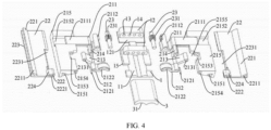
FIG. 4 is an exploded view of a hinge according to an embodiment of the present invention. - Reference numerals:
- 1. base; 11. arc-shaped shaft portion; 12. first mounting portion; 121. second notch; 13. third pivot hole; 14. fourth pivot hole; 15. base body;
- 2. rotating component; 21. rotating assembly; 211. first rod; 2111. second slide rail; 2112. second meshing tooth; 212. second rod; 2121. third slide rail; 2122. arc-shaped recess; 213. third rod; 2131. second pivot hole; 214. fourth rod; 215. connection member; 2151. first slide groove; 2152. second slide groove; 2153. first notch; 2154. first pivot hole; 2155. first avoidance groove;
- 22. floating plate; 221. first mounting position; 2211. first slide rail; 222. second mounting position; 2221. third slide hole; 223. floating plate body; 2231. second avoidance groove; 224. protrusion;
- 23. gear shaft; 231. first meshing tooth;
- 3. cover body; 31. third avoidance groove; 32. arc-shaped accommodation cavity.
- Embodiments of the present invention are described in detail below, and examples of the described embodiments are shown in accompanying drawings. The following embodiments described with reference to the accompanying drawings are exemplary and are intended to explain the present invention rather than limit the present invention.
- A hinge, a display module, and an electronic device according to embodiments of the present invention will be described below with reference to
FIGS. 1 to 4 . - As shown in
FIGS. 1 to 4 , the hinge according to the embodiments of the present invention includes a base 1 and a rotating component 2, the base 1 extends along a first direction, and the rotating component 2 includes a floatingplate 22 and a rotatingassembly 21. Afirst mounting position 221 and asecond mounting position 222 are on the floatingplate 22 and spaced apart along a second direction orthogonal to the first direction. A first end of the rotatingassembly 21 is pivotably coupled to the base 1, and a second end of the rotatingassembly 21 is pivotably coupled to thefirst mounting position 221 and thesecond mounting position 222. The rotatingassembly 21 is slidable relative to thesecond mounting position 222 along the second direction. - It can be understood that the first direction is an A direction in
FIG. 2 , i.e., a length direction of the base 1, and the second direction is a B direction inFIG. 2 , i.e., a width direction of the floatingplate 22. When the hinge is folded, the floatingplate 22 rotates about an axial direction of the first direction, and the second direction may always be orthogonal to the first direction. It should be noted that the first direction may be the length direction or a width direction of the base 1. The situation shown inFIG. 2 is merely an example and does not represent a limitation, and the embodiments of the present invention are not limited to the situation shown inFIG. 2 . - For the hinge according to the embodiments of the present invention, the second end of the rotating
assembly 21 is pivotably coupled to thefirst mounting position 221 and thesecond mounting position 222, and the rotatingassembly 21 is slidable relative to thesecond mounting position 222 along the second direction, so that the display module or the electronic device using the hinge can better support a screen by the floatingplate 22 when folded or unfolded, resulting in a better fit between the floatingplate 22 and the screen and achieving higher flatness. - It can be understood that, as shown in
FIGS. 1 to 4 , thesecond mounting position 222 is closer to the base 1 than thefirst mounting position 221. When the rotatingassembly 21 rotates about the first direction relative to the base 1, the rotatingassembly 21 may rotate relative to thefirst mounting position 221 of the floatingplate 22, and the rotatingassembly 21 may not only rotate relative to thesecond mounting position 222 of the floatingplate 22, but also slide relative to thesecond mounting position 222 along the second direction. Thus, the rotation of the floatingplate 22 can better adapt to a natural bending shape of the screen. As a result, when the display module or the electronic device using the hinge is in a folded state or an unfolded state, the floatingplate 22 may fully fit with the screen, and the hinge has a better fit with the screen, leading to higher flatness. In addition, a contour of the folded hinge exhibits a substantially teardrop shape, which can effectively support and protect the screen. - In some embodiments, as shown in
FIGS. 1 and4 , the rotatingassembly 21 includes afirst rod 211, asecond rod 212 and aconnection member 215. Thefirst rod 211 and thesecond rod 212 are arranged side by side on the base 1 and are rotatable relative to the base 1. Theconnection member 215 is slidable relative to thefirst rod 211. It can be understood that a pivot axis around which a first end of thefirst rod 211 pivots relative to the base 1 is in the same direction as the first direction; a width of theconnection member 215 extends substantially along the second direction; and thefirst rod 211 slides relative to thesecond rod 212 along a width direction of theconnection member 215. Theconnection member 215 is pivotably coupled to thefirst mounting position 221, so that theconnection member 215 is rotatable relative to the floatingplate 22. A first end of thesecond rod 212 is pivotably coupled to the base 1, and a second end of thesecond rod 212 is pivotably coupled to thesecond mounting position 222 and is slidable relative to thesecond mounting position 222. For the hinge according to the embodiments of the present invention, since the rotatingassembly 21 is configured with the above structure, the hinge can achieve a simple structure, a reasonable design, a small number of parts, and lower production and manufacturing costs. - Optionally, as shown in
FIGS. 1 and4 , the rotatingassembly 21 further includes athird rod 213, a first end of thethird rod 213 is pivotably coupled to theconnection member 215, and a second end of thethird rod 213 is pivotably coupled to thesecond rod 212. In the hinge according to the embodiments of the present invention, the arrangement of the third rod 213 a better linkage effect during the rotation of thesecond rod 212 and theconnection member 215. In addition, a rotation trajectory of the floatingplate 22 fits better with a bending trajectory of the screen when the hinge is folded or unfolded, improving a folding effect of the screen. - As shown in
FIG. 4 , theconnection member 215 includes afirst notch 2153, afirst pivot hole 2154 is on a side of thefirst notch 2153 along the first direction, and asecond pivot hole 2131 is in the first end of thethird rod 213. The first end of thethird rod 213 is in thefirst notch 2153. A first pivot member (not shown) is arranged in and passes through thefirst pivot hole 2154 and thesecond pivot hole 2131, so that the first end of thethird rod 213 is pivotably coupled in thefirst notch 2153. For example, the first pivot member may be a pin shaft. Thefirst pivot hole 2154 runs through two opposite sides of thefirst notch 2153. The first pivot member is detachably mounted in thefirst pivot hole 2154 and pivotably coupled to thesecond pivot hole 2131. In the hinge according to the embodiments of the present invention, the first end of thethird rod 213 is fitted in thefirst notch 2153, resulting in a more compact structure and a reasonable layout design of the hinge structure. - Optionally, as shown in
FIGS. 2 and4 , afirst avoidance groove 2155 is at a position adjacent to thefirst notch 2153 and is configured to avoid thesecond mounting position 222 and thesecond rod 212. In the embodiments of the present invention, the arrangement of thefirst avoidance groove 2155 can avoid interference during the rotation of the floatingplate 22 and thesecond rod 212 relative to theconnection member 215, so that the hinge can rotate more smoothly and flexibly, and the hinge can achieve a more compact structure and a reasonable layout design. - Optionally, the
first pivot hole 2154 is in communication with a side of theconnection member 215 along the first direction. It can be understood that when the first pivot member is mounted, an end of the first pivot member may be inserted into thefirst pivot hole 2154 from the side of theconnection member 215, which facilitates the assembly of the hinge and facilitates the processing and manufacturing. - Optionally, as shown in
FIGS. 1 and4 , the rotatingassembly 21 further includes afourth rod 214, a first end of thefourth rod 214 is pivotably coupled to thefirst rod 211, and a second end of thefourth rod 214 is pivotably coupled to thesecond rod 212. In the hinge according to the embodiments of the present invention, the arrangement of thefourth rod 214 allows a better linkage effect during the rotation of thefirst rod 211 and thesecond rod 212. In addition, the rotation trajectory of the floatingplate 22 fits better with the bending trajectory of the screen when the hinge is folded or unfolded, improving the folding effect of the screen. - Optionally, as shown in
FIGS. 2 and4 , a pivot axis of thefourth rod 214 relative to thethird rod 213 and a pivot axis of thethird rod 213 relative to thesecond rod 212 are on a common axis and parallel to the first direction. For example, thesecond rod 212, thethird rod 213 and thefourth rod 214 may be coupled in series through a common pin shaft, to enable thesecond rod 212, thethird rod 213 and thefourth rod 214 to rotate around the same axis, so that the linkage effect of the hinge can be further improved. In addition, a mounting space between thefirst rod 211 and thesecond rod 212 can be effectively used to make a thickness of the hinge small, which is conducive to a lightweight and thin design of the whole device, thus improving user experience. - Optionally, as shown in
FIGS. 2 and4 , thefirst rod 211, thefourth rod 214, thethird rod 213 and thesecond rod 212 are arranged side by side in the first direction. It can be understood that thefirst rod 211, thefourth rod 214, thethird rod 213 and thesecond rod 212 are arranged sequentially in the first direction. Alternatively, thethird rod 213 may be on a side of thefirst rod 211 or thesecond rod 212 or may be between thefirst rod 211 and thesecond rod 212. In the hinge according to the embodiments of the present invention, relative positions of thefirst rod 211, thesecond rod 212, thethird rod 213 and thefourth rod 214 may be adjusted according to actual needs, so that the hinge has a wider application range and a better support effect. - Optionally, as shown in
FIGS. 2 to 4 , afirst slide groove 2151 is in one of theconnection member 215 and thefirst mounting position 221, and afirst slide rail 2211 is on the other of theconnection member 215 and thefirst mounting position 221. For example, thefirst slide groove 2151 is in theconnection member 215, and thefirst slide rail 2211 is on thefirst mounting position 221. Thefirst slide rail 2211 is slidably fitted with thefirst slide groove 2151, thefirst slide groove 2151 extends along a first arc line, and an axis of the first arc line is in the same direction as the first direction. Thefirst slide rail 2211 is slidably fitted with thefirst slide groove 2151 along the first arc line, so that theconnection member 215 is rotatable relative to the floatingplate 22. It can be understood that when the hinge is folded, theconnection member 215 rotates relative to the floatingplate 22, so that thefirst slide rail 2211 slides into thefirst slide groove 2151 along the first arc line. When the hinge is unfolded, theconnection member 215 rotates relative to the floatingplate 22, so that part of thefirst slide rail 2211 gradually slides out of thefirst slide groove 2151 along the first arc line. As a result, the structure of connection between theconnection member 215 and the floatingplate 22 is reasonably designed and the reliability of connection is higher. In addition, the arrangement of thefirst slide rail 2211 and thefirst slide groove 2151 eliminates the need for any front opening in the floatingplate 22, and improves the support effect of the floatingplate 22 on the screen. - Optionally, as shown in
FIGS. 2 to 4 , asecond slide groove 2152 is in one of theconnection member 215 and thefirst rod 211, and asecond slide rail 2111 is on the other of theconnection member 215 and thefirst rod 211. For example, thesecond slide groove 2152 is in theconnection member 215, and thesecond slide rail 2111 is on thefirst rod 211. It can be understood that the width of theconnection member 215 generally extends along the second direction, and thesecond slide rail 2111 extends along the width direction of theconnection member 215 and is slidably fitted with thesecond slide groove 2152. In the hinge according to the embodiments of the present invention, the arrangement of thesecond slide rail 2111 and thesecond slide groove 2152 makes the structure of connection between theconnection member 215 and thefirst rod 211 more stable, and the structural design is simple, facilitating the processing and manufacturing and reducing production costs. - In some embodiments, as shown in
FIGS. 2 to 4 , athird slide hole 2221 is in one of thesecond rod 212 and thesecond mounting position 222, and athird slide rail 2121 is on the other of thesecond rod 212 and thesecond mounting position 222. For example, thethird slide rail 2121 is on a side of thesecond rod 212 adjacent to the floatingplate 22 and extends along the first direction. Thethird slide hole 2221 is formed in thesecond mounting position 222. An axial direction of thethird slide hole 2221 is parallel to the first direction. Thethird slide rail 2121 is in a clearance fit with thethird slide hole 2221, so that thethird slide rail 2121 is slidable relative to thethird slide hole 2221 along the second direction. In the hinge according to the embodiments of the present invention, the arrangement of thethird slide rail 2121 and thethird slide hole 2221 makes the structure of connection between thesecond rod 212 and the floatingplate 22 more stable, and the structural design is simple, facilitating the processing and manufacturing and reducing production costs. - Specifically, as shown in
FIGS. 2 and4 , the floatingplate 22 includes a floatingplate body 223, thefirst slide rail 2211, and aprotrusion 224. Thefirst slide rail 2211 is on a side of the floatingplate body 223 facing away from the base 1, and theprotrusion 224 is on a side of the floatingplate body 223 adjacent to the base 1. Thefirst slide rail 2211 constitutes thefirst mounting position 221, thethird slide hole 2221 is in theprotrusion 224, and thethird slide hole 2221 constitutes thesecond mounting position 222. Moreover, the floatingplate body 223 includes asecond avoidance groove 2231 arranged side by side with theprotrusion 224. Thesecond avoidance groove 2231 is configured to avoid thesecond rod 212, thethird rod 213 and thefourth rod 214. It can be understood that the interference during the rotation of thesecond rod 212, thethird rod 213 and thefourth rod 214 relative to the floatingplate 22 can be avoided by thesecond avoidance groove 2231, so that the hinge can rotate more smoothly and flexibly and achieve a more compact structure and a reasonable layout design. - In some embodiments, as shown in
FIG. 4 , the rotatingassembly 21 further includes a gear transmission pair having afirst meshing tooth 231, thefirst rod 211 has asecond meshing tooth 2112, and thefirst meshing tooth 231 meshes with thesecond meshing tooth 2112 to drive thefirst rod 211 to rotate relative to the base 1. Since the hinge may drive thefirst rod 211 to swing by the gear transmission pair, the rotation of the rotatingassembly 21 is more stable and more reliable. - Optionally, as shown in
FIG. 4 , the gear transmission pair includes agear shaft 23, thegear shaft 23 has thefirst meshing tooth 231, and thegear shaft 23 is pivotably coupled to the base 1. Optionally, the gear transmission pair includes thegear shaft 23 and a transmission gear (not shown), and thegear shaft 23 meshes with thesecond meshing tooth 2112 of thefirst rod 211 through the transmission gear. For example, one or a plurality of transmission gears may be provided, and the plurality of transmission gears mesh with each other to transmit power. - Optionally, as shown in
FIG. 4 , the base 1 includes asecond notch 121. Athird pivot hole 13 and afourth pivot hole 14 are on a side of thesecond notch 121 along the first direction. The first end of thefirst rod 211 is pivotably fitted in thethird pivot hole 13, and an end of thegear shaft 23 is pivotably fitted in thefourth pivot hole 14. It can be understood that thethird pivot hole 13 and thefourth pivot hole 14 may be arranged side by side, the first end of thefirst rod 211 may be detachably coupled to thethird pivot hole 13, and the end of thegear shaft 23 may be detachably coupled to thefourth pivot hole 14. As a result, the connection structure of the hinge can be more stable, and the production and assembly can be facilitated. - Optionally, as shown in
FIG. 4 , two first mountingportions 12 are on the base 1 and spaced apart along the first direction. For example, the first mountingportion 12 may be of a convex block structure. Thesecond notch 121 is defined between the two first mountingportions 12, and thethird pivot hole 13 and thefourth pivot hole 14 are in the first mountingportions 12, so that the structure of the base 1 can be more reasonable, enhancing the structural strength, and facilitates the processing and manufacturing. - In some embodiments, as shown in
FIGS. 2 to 4 , two groups of rotating components 2 are provided, and the two groups of rotating components 2 are pivotably coupled to two sides of the base 1. It can be understood that the two rotating components 2 may be unfolded and closed with the base 1 as a center. In an unfolded state, the two rotating components 2 and the base 1 between the two rotating components 2 form a plane. In a closed state, since the inside of the rotating components 2 may also rotate, the rotating components 2 may be completely closed, presenting a teardrop-shaped section after being closed. - As shown in
FIGS. 2 to 4 , the base 1 may be in the shape of a column, a plate shape or other shapes. The rotation connection between the base 1 and the rotating component 2 may be realized by a pivot connection or a hinge connection, or by sliding along an arc-shaped sliding path. The present invention is not limited thereto. - Specifically, as shown in
FIGS. 2 and4 , the rotatingassembly 21 of each group of rotating components 2 includes thegear shaft 23, and twogear shafts 23 are on two sides of the base 1 and are rotatable relative to the base 1. Eachgear shaft 23 has thefirst meshing tooth 231, thefirst rod 211 has thesecond meshing tooth 2112, thefirst meshing tooth 231 meshes with thesecond meshing tooth 2112. First meshingteeth 231 of the twogear shafts 23 mesh with each other. It can be understood that one of the twogear shafts 23 is coupled to a drive motor (not shown). Since thefirst meshing teeth 231 of the twogear shafts 23 mesh with each other, the drive motor may drive thegear shafts 23 to rotate, and the twogear shafts 23 rotate synchronously to drive the rotatingassemblies 21 on two sides of the base 1 to unfold or close synchronously. - In some embodiments, as shown in
FIGS. 2 to 4 , the hinge according to the embodiments of the present invention further includes acover body 3 on a lower end of the base 1. For example, thecover body 3 includes an avoidance structure corresponding to a mounting structure on the base 1, so that a pivot position of the base 1 and the rotatingassembly 21 may be covered, improving the reliability of the hinge in use. - Optionally, as shown in
FIG. 4 , an arc-shapedrecess 2122 is in one of thesecond rod 212 and the base 1, an arc-shapedshaft portion 11 is on the other of thesecond rod 212 and the base 1, and the arc-shapedrecess 2122 is pivotably coupled to the arc-shapedshaft portion 11. For example, the base 1 includes abase body 15 and the arc-shapedshaft portion 11. Two arc-shapedshaft portions 11 are provided and are arranged side by side and spaced apart along the width direction of the base 1. Thebase body 15 and the arc-shapedshaft portion 11 are integrally formed. The arc-shapedrecess 2122 is in thesecond rod 212 and has an arc-shaped concave surface. The arc-shaped concave surface is fitted with the arc-shapedshaft portion 11 and is rotatable relative to the arc-shaped shaft portion. Therefore, in the hinge according to the embodiments of the present invention, the arrangement of the arc-shapedrecess 2122 and the arc-shapedshaft portion 11 allows fewer parts during the assembly of the hinge, a reasonable structural design and good practicability. - Specifically, as shown in
FIGS. 3 and4 , thecover body 3 includes athird avoidance groove 31, and thethird avoidance groove 31 is on a side of thecover body 3 adjacent to the base 1. Twothird avoidance grooves 31 are provided, and the twothird avoidance grooves 31 are spaced apart and in one-to-one correspondence with the two arc-shapedshaft portions 11. An arc-shapedaccommodation cavity 32 is defined between thethird avoidance grooves 31 and the arc-shapedshaft portions 11, and the arc-shapedrecess 2122 may rotate in the arc-shapedaccommodation cavity 32. Thus, thesecond rod 212 can rotate more smoothly relative to the base 1, the number of used parts can be reduced, the structural design is compact, and the layout is reasonable. - A display module according to another embodiment of the present invention includes a screen and the hinge that is a hinge according to the embodiments of the present invention, and the floating
plate 22 supports the screen. It can be understood that the screen is on upper ends of the floatingplate 22 and the base 1, and fits with the floatingplate 22 and the base 1. In other words, a rear surface of the screen is coupled to an inner side of the hinge, and the screen may be folded and unfolded as the hinge is opened and closed. - An electronic device according to still another embodiment of the present invention includes the hinge according to the embodiments of the present invention or the display module according to the embodiments of the present invention.
- For the display module and the electronic device having the display module according to the embodiments of the present invention, the screen may be supported by the floating
plate 22. Since the second end of the rotatingassembly 21 is pivotably coupled to thefirst mounting position 221 and thesecond mounting position 222 and the rotatingassembly 21 is slidable relative to thesecond mounting position 222 along the second direction, the screen may be better supported by the floatingplate 22 when the display module is folded or unfolded, so that the floatingplate 22 has a better fit with the screen, resulting in higher flatness. - In addition, the rotating
assembly 21 of the hinge according to the embodiments of the present invention includes a plurality of linkage members, so that the hinge can have good stability during use, a reliable connection structure, fewer parts, and lower production and manufacturing costs. Moreover, when the display module and the electronic device having the hinge are in the folded state, the contour of the hinge exhibits the substantially teardrop shape, effectively supporting and protecting the screen, and the thickness of the whole device is small, which is conducive to realizing the lightweight and thin design of the electronic device and improving the user experience. - In the description of the present invention, it shall be understood that terms such as "central," "longitudinal," "transverse," "length," "width," "thickness," "upper," "lower," "front," "rear," "left," "right," "vertical," "horizontal," "top," "bottom," "inner," "outer," "clockwise," "counterclockwise," "axial," "radial" and "circumferential" should be construed to refer to the orientation as then described or as shown in the drawings under discussion. These relative terms are for convenience of description and do not indicate or imply that the device or element referred to must have a particular orientation, or be constructed and operated in a particular orientation. Thus, these terms shall not be construed as limitation on the present invention.
- In addition, terms such as "first" and "second" are merely used for descriptive purposes and cannot be understood as indicating or implying relative importance or the number of technical features indicated. Thus, the features associated with "first" and "second" may explicitly or implicitly include at least one of the features. In the description of the present invention, unless otherwise specifically defined, "a plurality of' means at least two, such as two, three, etc.
- In the present invention, unless otherwise explicitly specified and defined, the terms "mounted," "coupled," "connected," "fixed" and the like are used broadly, and may be, for example, fixed connections, detachable connections, or integral connections; may also be mechanical or electrical connections or intercommunication; may also be direct connections or indirect connections via intermediate media; may also be inner communications or interactions of two elements. For those skilled in the art, the specific meaning of the above terms in the present invention can be understood according to the specific circumstances.
- In the present invention, unless otherwise explicitly specified and defined, a structure in which a first feature is "on" or "below" a second feature may include an embodiment in which the first feature is in direct contact with the second feature, and may also include an embodiment in which the first feature and the second feature are not in direct contact with each other, but are contacted via an intermediate medium formed therebetween. Furthermore, a first feature "on," "above," or "on top of' a second feature may include an embodiment in which the first feature is right or obliquely "on," "above," or "on top of' the second feature, or just means that the first feature is at a height higher than that of the second feature; while a first feature "below," "under," or "on bottom of' a second feature may include an embodiment in which the first feature is right or obliquely "below," "under," or "on bottom of' the second feature, or just means that the first feature is at a height lower than that of the second feature.
- In the present invention, terms such as "an embodiment," "some embodiments," "an example," "a specific example," or "some examples," means that a particular feature, structure, material, or characteristic described in connection with the embodiment or example is included in at least one embodiment or example of the present invention. Thus, the appearances of these terms in various places throughout this specification are not necessarily referring to the same embodiment or example of the present invention. Furthermore, the particular features, structures, materials, or characteristics may be combined in any suitable manner in one or more embodiments or examples. In addition, without contradiction, those skilled in the art may combine and unite different embodiments or examples or features of the different embodiments or examples described in this specification.
- Although the above embodiments have been shown and described, it can be understood that the above embodiments are exemplary and shall not be understood as limitation to the present invention, and changes, modifications, alternatives and variations can be made in the above embodiments within the scope of the appended claims.
Claims (15)
- A hinge, comprising:a base (1) extending along a first direction; anda rotating component (2) comprising a floating plate (22) and a rotating assembly (21),wherein:a first end of the rotating assembly (21) is pivotably coupled to the base (1), and a second end of the rotating assembly (21) is pivotably coupled to a first mounting position (221) and a second mounting position (222) on the floating plate (22), the first mounting position (221) and the second mounting position (222) being spaced apart along a second direction that is orthogonal to the first direction; andthe rotating assembly (21) is slidable relative to the second mounting position (222) along the second direction.
- The hinge according to claim 1, wherein:the rotating assembly (21) comprises a first rod (211), a second rod (212) and a connection member (215);a first end of the first rod (211) is pivotably coupled to the base (1);the connection member (215) is slidable relative to the first rod (211), and the connection member (215) is pivotably coupled to the first mounting position (221);a first end of the second rod (212) is pivotably coupled to the base (1), and a second end of the second rod (212) is pivotably coupled to the second mounting position (222) and is slidable relative to the second mounting position (222).
- The hinge according to claim 2, wherein the rotating assembly (21) further comprises a third rod (213), a first end of the third rod (213) being pivotably coupled to the connection member (215), and a second end of the third rod (213) being pivotably coupled to the second rod (212).
- The hinge according to claim 3, wherein:a first notch (2153) is in the connection member (215), a first pivot hole (2154) is on a side of the first notch (2153) along the first direction, and a second pivot hole (2131) is in the first end of the third rod (213); anda first pivot member is inserted in and passes through the first pivot hole (2154) and the second pivot hole (2131), and the first notch (2153) is pivotably coupled to the first end of the third rod (213),especially, the first pivot hole (2154) is in communication with a side of the connection member (215) along the first direction.
- The hinge according to any one of claims 2 to 4, wherein the rotating assembly (21) further comprises a fourth rod (214), a first end of the fourth rod (214) being pivotably coupled to the first rod (211), and a second end of the fourth rod (214) being pivotably coupled to the second rod (212).
- The hinge according to claim 3 or 4, wherein:the rotating assembly (21) further comprises a fourth rod (214), a first end of the fourth rod (214) being pivotably coupled to the first rod (211), and a second end of the fourth rod (214) being pivotably coupled to the second end of the third rod (213);a pivot axis of the fourth rod (214) relative to the third rod (213) and a pivot axis of the third rod (213) relative to the second rod (212) are on a common axis and parallel to the first direction.
- The hinge according to any one of claims 2 to 6, wherein:a first slide groove (2151) is in one of the connection member (215) and the first mounting position (221), a first slide rail (2211) is on the other of the connection member (215) and the first mounting position (221), and the first slide rail (2211) is fitted with the first slide groove (2151);the first slide groove (2151) extends along a first arc line, an axis of the first arc line is in a same direction as the first direction, and the first slide rail (2211) is slidably fitted with the first slide groove (2151) along the first arc line, allowing the connection member (215) to rotate relative to the floating plate (22).
- The hinge according to any one of claims 2 to 7, wherein a second slide groove (2152) is in one of the connection member (215) and the first rod (211), a second slide rail (2111) is on the other of the connection member (215) and the first rod (211), and the second slide rail (2111) is slidably fitted with the second slide groove (2152) in a direction orthogonal to the first direction.
- The hinge according to any one of claims 2 to 8, wherein a third slide hole (2221) is in one of the second rod (212) and the second mounting position (222), a third slide rail (2121) is on the other of the second rod (212) and the second mounting position (222), and the third slide rail (2121) is pivotably coupled to the third slide hole (2221) and slidably fitted with the third slide hole (2221) along the second direction,
especially, the third slide rail (2121) is on a side of the second rod (212) adjacent to the floating plate (22) and extends along the first direction, the third slide hole (2221) is formed in the second mounting position (222), and an axial direction of the third slide hole (2221) is parallel to the first direction. - The hinge according to any one of claims 2 to 9, wherein an arc-shaped recess (2122) is in one of the second rod (212) and the base (1), an arc-shaped shaft portion (11) is on the other of the second rod (212) and the base (1), and the arc-shaped recess (2122) is pivotably coupled to the arc-shaped shaft portion (11).
- The hinge according to any one of claims 2 to 10, wherein the rotating assembly (21) further comprises a gear transmission pair having a first meshing tooth (231), the first rod (211) has a second meshing tooth (2112), and the first meshing tooth (231) meshes with the second meshing tooth (2112) to drive the first rod (211) to rotate relative to the base (1).
- The hinge according to claim 11, wherein the gear transmission pair comprises a gear shaft (23), the first meshing tooth (231) is on the gear shaft (23), and the gear shaft (23) is pivotably coupled to the base (1).
- The hinge according to claim 12, wherein the base (1) comprises a second notch (121), a third pivot hole (13) and a fourth pivot hole (14) are on a side of the second notch (121) along the first direction, the first end of the first rod (211) is pivotably fitted in the third pivot hole (13), and an end of the gear shaft (23) is pivotably fitted in the fourth pivot hole (14).
- A display module, comprising:a screen; andthe hinge according to any one of claims 1 to 13, wherein the floating plate (22) supports the screen.
- An electronic device, comprising the hinge according to any one of claims 1 to 13 or the display module according to claim 14.
Applications Claiming Priority (1)
| Application Number | Priority Date | Filing Date | Title |
|---|---|---|---|
| CN202210216544.6A CN116781807A (en) | 2022-03-07 | 2022-03-07 | Hinges, display modules and electronic devices |
Publications (2)
| Publication Number | Publication Date |
|---|---|
| EP4243384A1 true EP4243384A1 (en) | 2023-09-13 |
| EP4243384B1 EP4243384B1 (en) | 2025-09-03 |
Family
ID=83059186
Family Applications (1)
| Application Number | Title | Priority Date | Filing Date |
|---|---|---|---|
| EP22187592.5A Active EP4243384B1 (en) | 2022-03-07 | 2022-07-28 | Hinge, display module and electronic device |
Country Status (3)
| Country | Link |
|---|---|
| US (1) | US11994161B2 (en) |
| EP (1) | EP4243384B1 (en) |
| CN (1) | CN116781807A (en) |
Families Citing this family (16)
| Publication number | Priority date | Publication date | Assignee | Title |
|---|---|---|---|---|
| PL4185759T3 (en) * | 2020-09-22 | 2024-09-16 | Sfs Intec Ag | Hidden hinge for flush or rebated door or window applications |
| KR102896994B1 (en) * | 2020-10-20 | 2025-12-08 | 삼성전자주식회사 | A hinge module and foldable electronic device including the same |
| CN115842883B (en) * | 2021-09-18 | 2023-10-24 | 荣耀终端有限公司 | Folding assembly of electronic equipment and electronic equipment |
| CN115883701B (en) * | 2021-09-18 | 2024-11-12 | 荣耀终端有限公司 | Folding assembly of electronic device and electronic device |
| WO2023044910A1 (en) * | 2021-09-27 | 2023-03-30 | Boe Technology Group Co., Ltd. | Pivotable support apparatus and display apparatus |
| CN114046313B (en) * | 2021-11-25 | 2023-08-22 | 武汉华星光电半导体显示技术有限公司 | Hinge, display panel and electronic device |
| CN114165514B (en) * | 2021-12-13 | 2023-01-10 | 武汉华星光电半导体显示技术有限公司 | Flexible display panel and electronic device |
| KR20230131384A (en) * | 2022-03-04 | 2023-09-13 | 삼성디스플레이 주식회사 | display device |
| KR20230156209A (en) * | 2022-05-04 | 2023-11-14 | 삼성디스플레이 주식회사 | Jig for testing flexible panel and display device including the same |
| US12219723B2 (en) * | 2022-06-14 | 2025-02-04 | Microsoft Technology Licensing, Llc | Hinged device having slot defined hinge trajectories |
| US20250068214A1 (en) * | 2022-06-20 | 2025-02-27 | Beijing Xiaomi Mobile Software Co., Ltd. | Hinge structure and electronic device |
| US12432287B2 (en) * | 2022-09-01 | 2025-09-30 | Syncmold Enterprise Corp. | Foldable electronic device |
| TWI808037B (en) * | 2022-11-10 | 2023-07-01 | 富世達股份有限公司 | Hinge |
| TWI835429B (en) * | 2022-11-28 | 2024-03-11 | 富世達股份有限公司 | hinge |
| TWI899009B (en) * | 2024-07-12 | 2025-09-21 | 信錦企業股份有限公司 | Foldable electronic device |
| WO2026050919A1 (en) * | 2024-09-04 | 2026-03-12 | 瑞声光电科技(常州)有限公司 | Automatic synchronization hinge apparatus and electronic device |
Citations (3)
| Publication number | Priority date | Publication date | Assignee | Title |
|---|---|---|---|---|
| CN110784570A (en) * | 2019-10-29 | 2020-02-11 | Oppo广东移动通信有限公司 | Folding devices and electronic equipment |
| US20200103935A1 (en) * | 2018-09-27 | 2020-04-02 | Jarllytec Co.,Ltd. | Hinge module for a foldable type device |
| WO2022001769A1 (en) * | 2020-06-30 | 2022-01-06 | 华为技术有限公司 | Rotating shaft mechanism and foldable mobile terminal |
Family Cites Families (4)
| Publication number | Priority date | Publication date | Assignee | Title |
|---|---|---|---|---|
| TWM421401U (en) * | 2011-07-26 | 2012-01-21 | Wistron Corp | Hinge and electronic device with the same |
| US10895894B2 (en) * | 2018-12-25 | 2021-01-19 | Compal Electronics, Inc. | Electronic device |
| JP7668516B2 (en) * | 2020-10-29 | 2025-04-25 | 株式会社ナチュラレーザ・ワン | Multi-axis hinge device and electronic device using the multi-axis hinge device |
| CN112991958B (en) * | 2021-03-29 | 2023-02-21 | 维沃移动通信有限公司 | Electronic equipment |
-
2022
- 2022-03-07 CN CN202210216544.6A patent/CN116781807A/en active Pending
- 2022-07-28 EP EP22187592.5A patent/EP4243384B1/en active Active
- 2022-07-28 US US17/876,173 patent/US11994161B2/en active Active
Patent Citations (4)
| Publication number | Priority date | Publication date | Assignee | Title |
|---|---|---|---|---|
| US20200103935A1 (en) * | 2018-09-27 | 2020-04-02 | Jarllytec Co.,Ltd. | Hinge module for a foldable type device |
| CN110784570A (en) * | 2019-10-29 | 2020-02-11 | Oppo广东移动通信有限公司 | Folding devices and electronic equipment |
| US20220217228A1 (en) * | 2019-10-29 | 2022-07-07 | Guangdong Oppo Mobile Telecommunications Corp., Ltd. | Foldable apparatus and electronic device |
| WO2022001769A1 (en) * | 2020-06-30 | 2022-01-06 | 华为技术有限公司 | Rotating shaft mechanism and foldable mobile terminal |
Also Published As
| Publication number | Publication date |
|---|---|
| US11994161B2 (en) | 2024-05-28 |
| CN116781807A (en) | 2023-09-19 |
| EP4243384B1 (en) | 2025-09-03 |
| US20230279898A1 (en) | 2023-09-07 |
Similar Documents
| Publication | Publication Date | Title |
|---|---|---|
| EP4243384A1 (en) | Hinge, display module and electronic device | |
| CN214507124U (en) | Hinge and flexible screen mobile terminal of infolding | |
| EP4092505B1 (en) | Rotating module and electronic device | |
| US20240028084A1 (en) | Foldable hinge and foldable display device | |
| CN109495621A (en) | Folding mechanism and mobile terminal | |
| EP3806435B1 (en) | Hinge and mobile terminal | |
| EP4187354A1 (en) | Coupling device and terminal equipment | |
| CN113404770A (en) | Hinge, display panel and electronic device | |
| CN214507123U (en) | Novel hinge and flexible screen mobile terminal of infolding | |
| CN111503458B (en) | Electronic equipment | |
| US12556625B2 (en) | Rotating shaft mechanism and terminal device | |
| CN114810805A (en) | Hinge, display panel and mobile terminal | |
| KR20240159659A (en) | Hinge mechanism and electronics | |
| WO2024140514A1 (en) | Hinge mechanism and electronic device | |
| KR20240159661A (en) | Hinge mechanism and electronics | |
| US11733735B2 (en) | Support assembly, foldable display screen and terminal device | |
| CN113719523A (en) | Hinge mechanism, folding device and electronic equipment | |
| CN115405614A (en) | Hinge structure and electronic device | |
| CN109854610B (en) | Connecting rod rotary hinge, folding mechanism and electronic terminal | |
| CN116412199A (en) | Hinge mechanism and mobile terminal | |
| CN222351153U (en) | Floating plate adjusting mechanism, folding mechanism and electronic equipment | |
| CN116592046B (en) | A hinge device and a folding display device | |
| CN223725146U (en) | Floating plate, hinge mechanism and electronic equipment | |
| CN223120406U (en) | Folding hinge and flexible screen folding mechanism | |
| CN218183376U (en) | Hinge of outer flexible screen mobile terminal and outer flexible screen mobile terminal |
Legal Events
| Date | Code | Title | Description |
|---|---|---|---|
| PUAI | Public reference made under article 153(3) epc to a published international application that has entered the european phase |
Free format text: ORIGINAL CODE: 0009012 |
|
| STAA | Information on the status of an ep patent application or granted ep patent |
Free format text: STATUS: REQUEST FOR EXAMINATION WAS MADE |
|
| 17P | Request for examination filed |
Effective date: 20220728 |
|
| AK | Designated contracting states |
Kind code of ref document: A1 Designated state(s): AL AT BE BG CH CY CZ DE DK EE ES FI FR GB GR HR HU IE IS IT LI LT LU LV MC MK MT NL NO PL PT RO RS SE SI SK SM TR |
|
| GRAP | Despatch of communication of intention to grant a patent |
Free format text: ORIGINAL CODE: EPIDOSNIGR1 |
|
| STAA | Information on the status of an ep patent application or granted ep patent |
Free format text: STATUS: GRANT OF PATENT IS INTENDED |
|
| INTG | Intention to grant announced |
Effective date: 20250403 |
|
| P01 | Opt-out of the competence of the unified patent court (upc) registered |
Free format text: CASE NUMBER: APP_21398/2025 Effective date: 20250506 |
|
| GRAS | Grant fee paid |
Free format text: ORIGINAL CODE: EPIDOSNIGR3 |
|
| GRAA | (expected) grant |
Free format text: ORIGINAL CODE: 0009210 |
|
| STAA | Information on the status of an ep patent application or granted ep patent |
Free format text: STATUS: THE PATENT HAS BEEN GRANTED |
|
| AK | Designated contracting states |
Kind code of ref document: B1 Designated state(s): AL AT BE BG CH CY CZ DE DK EE ES FI FR GB GR HR HU IE IS IT LI LT LU LV MC MK MT NL NO PL PT RO RS SE SI SK SM TR |
|
| REG | Reference to a national code |
Ref country code: CH Ref legal event code: EP |
|
| REG | Reference to a national code |
Ref country code: DE Ref legal event code: R096 Ref document number: 602022020621 Country of ref document: DE |
|
| REG | Reference to a national code |
Ref country code: IE Ref legal event code: FG4D |
|
| REG | Reference to a national code |
Ref country code: NL Ref legal event code: MP Effective date: 20250903 |
|
| PG25 | Lapsed in a contracting state [announced via postgrant information from national office to epo] |
Ref country code: NO Free format text: LAPSE BECAUSE OF FAILURE TO SUBMIT A TRANSLATION OF THE DESCRIPTION OR TO PAY THE FEE WITHIN THE PRESCRIBED TIME-LIMIT Effective date: 20251203 |
|
| REG | Reference to a national code |
Ref country code: LT Ref legal event code: MG9D |
|
| PG25 | Lapsed in a contracting state [announced via postgrant information from national office to epo] |
Ref country code: FI Free format text: LAPSE BECAUSE OF FAILURE TO SUBMIT A TRANSLATION OF THE DESCRIPTION OR TO PAY THE FEE WITHIN THE PRESCRIBED TIME-LIMIT Effective date: 20250903 |
|
| PG25 | Lapsed in a contracting state [announced via postgrant information from national office to epo] |
Ref country code: HR Free format text: LAPSE BECAUSE OF FAILURE TO SUBMIT A TRANSLATION OF THE DESCRIPTION OR TO PAY THE FEE WITHIN THE PRESCRIBED TIME-LIMIT Effective date: 20250903 |
|
| PG25 | Lapsed in a contracting state [announced via postgrant information from national office to epo] |
Ref country code: GR Free format text: LAPSE BECAUSE OF FAILURE TO SUBMIT A TRANSLATION OF THE DESCRIPTION OR TO PAY THE FEE WITHIN THE PRESCRIBED TIME-LIMIT Effective date: 20251204 |
|
| PG25 | Lapsed in a contracting state [announced via postgrant information from national office to epo] |
Ref country code: SE Free format text: LAPSE BECAUSE OF FAILURE TO SUBMIT A TRANSLATION OF THE DESCRIPTION OR TO PAY THE FEE WITHIN THE PRESCRIBED TIME-LIMIT Effective date: 20250903 |
|
| PG25 | Lapsed in a contracting state [announced via postgrant information from national office to epo] |
Ref country code: LV Free format text: LAPSE BECAUSE OF FAILURE TO SUBMIT A TRANSLATION OF THE DESCRIPTION OR TO PAY THE FEE WITHIN THE PRESCRIBED TIME-LIMIT Effective date: 20250903 |
|
| PG25 | Lapsed in a contracting state [announced via postgrant information from national office to epo] |
Ref country code: BG Free format text: LAPSE BECAUSE OF FAILURE TO SUBMIT A TRANSLATION OF THE DESCRIPTION OR TO PAY THE FEE WITHIN THE PRESCRIBED TIME-LIMIT Effective date: 20250903 Ref country code: PL Free format text: LAPSE BECAUSE OF FAILURE TO SUBMIT A TRANSLATION OF THE DESCRIPTION OR TO PAY THE FEE WITHIN THE PRESCRIBED TIME-LIMIT Effective date: 20250903 |
|
| PG25 | Lapsed in a contracting state [announced via postgrant information from national office to epo] |
Ref country code: RS Free format text: LAPSE BECAUSE OF FAILURE TO SUBMIT A TRANSLATION OF THE DESCRIPTION OR TO PAY THE FEE WITHIN THE PRESCRIBED TIME-LIMIT Effective date: 20251203 |
|
| PG25 | Lapsed in a contracting state [announced via postgrant information from national office to epo] |
Ref country code: ES Free format text: LAPSE BECAUSE OF FAILURE TO SUBMIT A TRANSLATION OF THE DESCRIPTION OR TO PAY THE FEE WITHIN THE PRESCRIBED TIME-LIMIT Effective date: 20250903 |
|
| REG | Reference to a national code |
Ref country code: AT Ref legal event code: MK05 Ref document number: 1834583 Country of ref document: AT Kind code of ref document: T Effective date: 20250903 |
|
| PG25 | Lapsed in a contracting state [announced via postgrant information from national office to epo] |
Ref country code: NL Free format text: LAPSE BECAUSE OF FAILURE TO SUBMIT A TRANSLATION OF THE DESCRIPTION OR TO PAY THE FEE WITHIN THE PRESCRIBED TIME-LIMIT Effective date: 20250903 |
|
| PG25 | Lapsed in a contracting state [announced via postgrant information from national office to epo] |
Ref country code: SM Free format text: LAPSE BECAUSE OF FAILURE TO SUBMIT A TRANSLATION OF THE DESCRIPTION OR TO PAY THE FEE WITHIN THE PRESCRIBED TIME-LIMIT Effective date: 20250903 |
|
| PG25 | Lapsed in a contracting state [announced via postgrant information from national office to epo] |
Ref country code: AT Free format text: LAPSE BECAUSE OF FAILURE TO SUBMIT A TRANSLATION OF THE DESCRIPTION OR TO PAY THE FEE WITHIN THE PRESCRIBED TIME-LIMIT Effective date: 20250903 |
|
| PG25 | Lapsed in a contracting state [announced via postgrant information from national office to epo] |
Ref country code: IT Free format text: LAPSE BECAUSE OF FAILURE TO SUBMIT A TRANSLATION OF THE DESCRIPTION OR TO PAY THE FEE WITHIN THE PRESCRIBED TIME-LIMIT Effective date: 20250903 |
|
| PG25 | Lapsed in a contracting state [announced via postgrant information from national office to epo] |
Ref country code: IS Free format text: LAPSE BECAUSE OF FAILURE TO SUBMIT A TRANSLATION OF THE DESCRIPTION OR TO PAY THE FEE WITHIN THE PRESCRIBED TIME-LIMIT Effective date: 20260103 |
|
| PG25 | Lapsed in a contracting state [announced via postgrant information from national office to epo] |
Ref country code: PT Free format text: LAPSE BECAUSE OF FAILURE TO SUBMIT A TRANSLATION OF THE DESCRIPTION OR TO PAY THE FEE WITHIN THE PRESCRIBED TIME-LIMIT Effective date: 20260105 Ref country code: CZ Free format text: LAPSE BECAUSE OF FAILURE TO SUBMIT A TRANSLATION OF THE DESCRIPTION OR TO PAY THE FEE WITHIN THE PRESCRIBED TIME-LIMIT Effective date: 20250903 |
|
| PG25 | Lapsed in a contracting state [announced via postgrant information from national office to epo] |
Ref country code: EE Free format text: LAPSE BECAUSE OF FAILURE TO SUBMIT A TRANSLATION OF THE DESCRIPTION OR TO PAY THE FEE WITHIN THE PRESCRIBED TIME-LIMIT Effective date: 20250903 Ref country code: SK Free format text: LAPSE BECAUSE OF FAILURE TO SUBMIT A TRANSLATION OF THE DESCRIPTION OR TO PAY THE FEE WITHIN THE PRESCRIBED TIME-LIMIT Effective date: 20250903 |