EP4243363A2 - Method and device for quality of service regulation - Google Patents
Method and device for quality of service regulation Download PDFInfo
- Publication number
- EP4243363A2 EP4243363A2 EP23177550.3A EP23177550A EP4243363A2 EP 4243363 A2 EP4243363 A2 EP 4243363A2 EP 23177550 A EP23177550 A EP 23177550A EP 4243363 A2 EP4243363 A2 EP 4243363A2
- Authority
- EP
- European Patent Office
- Prior art keywords
- tunnel
- operator network
- implementations
- network
- service provider
- Prior art date
- Legal status (The legal status is an assumption and is not a legal conclusion. Google has not performed a legal analysis and makes no representation as to the accuracy of the status listed.)
- Pending
Links
- 238000000034 method Methods 0.000 title claims abstract description 78
- 230000005641 tunneling Effects 0.000 claims abstract description 66
- 230000004044 response Effects 0.000 claims abstract description 48
- 230000003595 spectral effect Effects 0.000 claims description 20
- 230000008859 change Effects 0.000 claims description 9
- 238000004891 communication Methods 0.000 description 19
- 230000006870 function Effects 0.000 description 19
- 238000007726 management method Methods 0.000 description 17
- 238000010586 diagram Methods 0.000 description 14
- 238000012384 transportation and delivery Methods 0.000 description 10
- 238000005516 engineering process Methods 0.000 description 9
- 230000008569 process Effects 0.000 description 6
- 230000007774 longterm Effects 0.000 description 5
- 238000012512 characterization method Methods 0.000 description 3
- 230000010354 integration Effects 0.000 description 3
- 238000012946 outsourcing Methods 0.000 description 3
- 238000001228 spectrum Methods 0.000 description 3
- 230000002776 aggregation Effects 0.000 description 2
- 238000004220 aggregation Methods 0.000 description 2
- 230000001413 cellular effect Effects 0.000 description 2
- 238000013523 data management Methods 0.000 description 2
- 230000006855 networking Effects 0.000 description 2
- 238000003908 quality control method Methods 0.000 description 2
- 238000006243 chemical reaction Methods 0.000 description 1
- 230000008867 communication pathway Effects 0.000 description 1
- 230000001419 dependent effect Effects 0.000 description 1
- 238000001514 detection method Methods 0.000 description 1
- 238000011161 development Methods 0.000 description 1
- 239000000835 fiber Substances 0.000 description 1
- 238000002955 isolation Methods 0.000 description 1
- 238000012423 maintenance Methods 0.000 description 1
- 230000003287 optical effect Effects 0.000 description 1
- 238000012545 processing Methods 0.000 description 1
- VEMKTZHHVJILDY-UHFFFAOYSA-N resmethrin Chemical compound CC1(C)C(C=C(C)C)C1C(=O)OCC1=COC(CC=2C=CC=CC=2)=C1 VEMKTZHHVJILDY-UHFFFAOYSA-N 0.000 description 1
- 239000007787 solid Substances 0.000 description 1
- 239000013589 supplement Substances 0.000 description 1
Images




Classifications
-
- H—ELECTRICITY
- H04—ELECTRIC COMMUNICATION TECHNIQUE
- H04L—TRANSMISSION OF DIGITAL INFORMATION, e.g. TELEGRAPHIC COMMUNICATION
- H04L41/00—Arrangements for maintenance, administration or management of data switching networks, e.g. of packet switching networks
- H04L41/50—Network service management, e.g. ensuring proper service fulfilment according to agreements
- H04L41/5041—Network service management, e.g. ensuring proper service fulfilment according to agreements characterised by the time relationship between creation and deployment of a service
- H04L41/5051—Service on demand, e.g. definition and deployment of services in real time
-
- H—ELECTRICITY
- H04—ELECTRIC COMMUNICATION TECHNIQUE
- H04L—TRANSMISSION OF DIGITAL INFORMATION, e.g. TELEGRAPHIC COMMUNICATION
- H04L12/00—Data switching networks
- H04L12/28—Data switching networks characterised by path configuration, e.g. LAN [Local Area Networks] or WAN [Wide Area Networks]
- H04L12/46—Interconnection of networks
- H04L12/4633—Interconnection of networks using encapsulation techniques, e.g. tunneling
-
- H—ELECTRICITY
- H04—ELECTRIC COMMUNICATION TECHNIQUE
- H04L—TRANSMISSION OF DIGITAL INFORMATION, e.g. TELEGRAPHIC COMMUNICATION
- H04L41/00—Arrangements for maintenance, administration or management of data switching networks, e.g. of packet switching networks
- H04L41/08—Configuration management of networks or network elements
- H04L41/0893—Assignment of logical groups to network elements
-
- H—ELECTRICITY
- H04—ELECTRIC COMMUNICATION TECHNIQUE
- H04L—TRANSMISSION OF DIGITAL INFORMATION, e.g. TELEGRAPHIC COMMUNICATION
- H04L41/00—Arrangements for maintenance, administration or management of data switching networks, e.g. of packet switching networks
- H04L41/08—Configuration management of networks or network elements
- H04L41/0896—Bandwidth or capacity management, i.e. automatically increasing or decreasing capacities
-
- H—ELECTRICITY
- H04—ELECTRIC COMMUNICATION TECHNIQUE
- H04L—TRANSMISSION OF DIGITAL INFORMATION, e.g. TELEGRAPHIC COMMUNICATION
- H04L43/00—Arrangements for monitoring or testing data switching networks
- H04L43/08—Monitoring or testing based on specific metrics, e.g. QoS, energy consumption or environmental parameters
-
- H—ELECTRICITY
- H04—ELECTRIC COMMUNICATION TECHNIQUE
- H04L—TRANSMISSION OF DIGITAL INFORMATION, e.g. TELEGRAPHIC COMMUNICATION
- H04L41/00—Arrangements for maintenance, administration or management of data switching networks, e.g. of packet switching networks
- H04L41/08—Configuration management of networks or network elements
- H04L41/0894—Policy-based network configuration management
-
- H—ELECTRICITY
- H04—ELECTRIC COMMUNICATION TECHNIQUE
- H04L—TRANSMISSION OF DIGITAL INFORMATION, e.g. TELEGRAPHIC COMMUNICATION
- H04L41/00—Arrangements for maintenance, administration or management of data switching networks, e.g. of packet switching networks
- H04L41/50—Network service management, e.g. ensuring proper service fulfilment according to agreements
- H04L41/5003—Managing SLA; Interaction between SLA and QoS
- H04L41/5019—Ensuring fulfilment of SLA
-
- H—ELECTRICITY
- H04—ELECTRIC COMMUNICATION TECHNIQUE
- H04W—WIRELESS COMMUNICATION NETWORKS
- H04W84/00—Network topologies
- H04W84/02—Hierarchically pre-organised networks, e.g. paging networks, cellular networks, WLAN [Wireless Local Area Network] or WLL [Wireless Local Loop]
- H04W84/04—Large scale networks; Deep hierarchical networks
- H04W84/042—Public Land Mobile systems, e.g. cellular systems
-
- H—ELECTRICITY
- H04—ELECTRIC COMMUNICATION TECHNIQUE
- H04W—WIRELESS COMMUNICATION NETWORKS
- H04W88/00—Devices specially adapted for wireless communication networks, e.g. terminals, base stations or access point devices
- H04W88/16—Gateway arrangements
Definitions
- the present disclosure generally relates to content delivery, and in particular, to systems, methods, and devices for quality of service regulation.
- MNOs Mobile network operators
- Such services include, but are not limited to, radio spectrum allocation, wireless network infrastructure, and Quality of Service (QoS) parameters.
- QoS Quality of Service
- GSPs guest service providers
- GSPs do not have access to certain radio spectrum resources or have a complete infrastructure in place.
- the MNOs supplement GSPs so that the GSPs are able to provide their own wireless communications services.
- QoS has been under-managed and under-utilized by MNOs due to a lack of policy management enforcement tools necessary to accommodate GSPs such as mobile virtual network operators (MVNOs), enterprises, application providers, roaming partner service providers, or the like.
- MVNOs mobile virtual network operators
- enterprises application providers
- roaming partner service providers or the like.
- MNOs share active and passive radio access system infrastructure such as base stations and network gateways.
- RF radio frequency
- a method is performed at a gateway node with one or more processors, non-transitory memory, and a data interface.
- the method includes obtaining a request to instantiate a tunnel for a data flow from a guest service provider to a user device that traverses an operator network.
- the method also includes determining whether the request satisfies tunneling criteria, where the tunneling criteria at least includes a first criterion associated with intrinsic information associated with the operator network and a second criterion associated with extrinsic information that quantitatively characterizes network resources of the network operator allocated to the guest service provider based on a predefined relationship between the operator network and the guest service provider.
- the method further includes instantiating the tunnel for the data flow between the operator network and the guest service provider in response to determining that the request satisfies the tunneling criteria, where instantiating the tunnel for the data flow includes the gateway node transmitting tunnel instructions to other nodes of the operator network.
- the method further includes routing the data flow through the tunnel in order to transmit the data flow to the user device.
- a device includes one or more processors, a non-transitory memory, and one or more programs; the one or more programs are stored in the non-transitory memory and configured to be executed by the one or more processors and the one or more programs include instructions for performing or causing performance of any of the methods described herein.
- a non-transitory computer readable storage medium has stored therein instructions, which, when executed by one or more processors of a device, cause the device to perform or cause performance of any of the methods described herein.
- a device includes: one or more processors, a non-transitory memory, and means for performing or causing performance of any of the methods described herein.
- GSPs guest service providers
- MVNOs mobile virtual network operators
- This invention deals with the MNO's ability to manage and process QoS requests to its radio access network (RAN) from application and service partners who are not part of the MNO's internal trusted application set.
- the invention safely allows an GSP to control radio frequency (RF) resources (e.g., spectral usage) in a host network by introducing a QoS-regulator feature in the host network that acts as a gatekeeper/policy enforcer for QoS requests.
- RF radio frequency
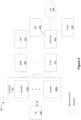
- FIG. 1 is a block diagram of an example data delivery environment 100 in accordance with some implementations. While pertinent features are shown, those of ordinary skill in the art will appreciate from the present disclosure that various other features have not been illustrated for the sake of brevity and so as not to obscure more pertinent aspects of the example implementations disclosed herein. To that end, as a non-limiting example, the data delivery environment 100 includes an operator network 104 that receives and transmits data between user equipment (UE) 102 and a guest service provider (GSP) 116. In some implementations, the operator network 104 also receives data from and transmits data to one or more external networks 118.
- UE user equipment
- GSP guest service provider
- the UE 102 includes a suitable combination of hardware (physical or virtualized), software, and/or firmware.
- Figure 1 depicts one UE 102
- the data delivery environment 100 includes an arbitrary number of UEs in various other implementations.
- the UE 102 corresponds to a desktop computer, laptop computer, mobile phone, tablet, wearable computing device, set-top box (STB), over-the-top (OTT) box, gaming console, or the like.
- STB set-top box
- OTT over-the-top
- the operator network 104 includes one or more access networks (ANs) 106, a core network 110, one or more operator network services 112, and a gateway regulator node 114. In some implementations, the operator network 104 optionally includes an aggregation network 108. In some implementations, the operator network 104 corresponds to a telecommunications service provider that provides wireless communication functionalities to a user/subscriber associated with the UE 102 such as a mobile network operator (MNO) that provides mobile access to content and communications. In some implementations, the operator network 104 corresponds more generally to a service provider (SP) that provides mobile access, fixed access, satellite access, or the like to content and communications.
- SP service provider
- the operator network 104 also receives and transmits data to one or more external networks 118, which optionally includes receiving data from and transmitting data to the Internet, content delivery network (CDN) servers, application servers, or the like.
- external networks 118 optionally includes receiving data from and transmitting data to the Internet, content delivery network (CDN) servers, application servers, or the like.
- CDN content delivery network
- At least one of the one or more ANs 106 implements radio access technology to provide connectivity via wireless communication to the UE 102 communicatively connected to the operator network 104.
- at least one of the one or more ANs 106 corresponds to a Long-Term Evolution (LTE) mobile access network (sometimes also referred to as 4G) that includes evolved node B (eNodeB) access nodes and the like.
- LTE Long-Term Evolution
- eNodeB evolved node B
- at least one of the one or more ANs 106 correspond to a 5G mobile access network that includes 5G base stations and the like.
- At least one of the one or more ANs 106 implements non-radio access technology to provide connectivity via wired or wireless communication to the UE 102 communicatively connected to the operator network 104.
- the non-radio access technology includes an IEEE 802.11x Wi-Fi network, a fiber optic network, an IEEE 802.3x Ethernet network, or the like.
- At least one of the one or more ANs 106 implements heterogeneous access technology via wired or wireless communication to the UE 102 communicatively connected to the operator network 104.
- the heterogeneous access technology includes a combination of radio access and non-radio access technologies.
- the core network 110 provides internet protocol (IP) routing and forwarding for a data flow between end points.
- IP internet protocol
- the end points include the one or more operator network services 112, the one or more external networks 118, the gateway regulator node 114, or the like.
- the one or more operator network services 112 include wireless communication services to control the elements of the operator network 104 in order to monitor and deliver services to an end user (e.g., the UE 102).
- the one or more operator network services 112 optionally include radio spectrum allocation management, infrastructure and networking management, QoS policy enforcement, billing services, customer support services, security auditing services, infrastructure and networking maintenance, and/or the like.
- the one or more operator network services 112 include content delivery services such as an IP multimedia subsystem (IMS).
- the one or more operator network services 112 include communication services such as voice-over Long-Term Evolution (VoLTE) or voice-over Internet Protocol (VoIP).
- VoIP voice-over Long-Term Evolution
- VoIP voice-over Internet Protocol
- the aggregation network 108 combines multiple network connections in parallel to increase throughput and to provide redundancies in case one of the network connections should fail.
- the operator network 104 includes the gateway regulator node 114 that serves as an interface node between the operator network 104 and the guest service provider 116.
- the gateway regulator node 114 includes a suitable combination of hardware (physical or virtualized), software, and/or firmware to maintain communication protocols between the operator network 104 and the guest service provider 116.
- the gateway regulator node 114 is configured to translate and map gateway interconnects for networks with different protocol technologies by performing protocol conversions.
- the networks with different protocol technologies include the operator network 104 and the guest service provider 116.
- the guest service provider 116 corresponds to one of an MVNO 118, an enterprise 120, an applications/OTT provider 122, one or more roaming partner SPs 124, or the like. In some implementations, the guest service provider 116 is not affiliated with the operator network 104. In one example, the guest service provider 116 does not include policy management.
- the MVNO 118 corresponds to a telecommunications service provider that has an agreement with the operator network 104 to provide its subscribers with telecommunications capabilities using the infrastructure of the operator network 104.
- the enterprise 120 corresponds to a telecommunications service provider that provides consulting, system integration, software development, outsourcing and/or the like.
- the applications/OTT provider 122 corresponds to a telecommunications service provider that delivers one or more services across an IP network without requiring its users to subscribe to a traditional service provider.
- the one or more roaming partner SPs 124 correspond to one or more telecommunications service providers that have cooperative agreements to grant subscribers local access to the network.
- FIG 2 is a block diagram of an example operator network 200 in accordance with some implementations. While pertinent features are shown, those of ordinary skill in the art will appreciate from the present disclosure that various other features have not been illustrated for the sake of brevity and so as not to obscure more pertinent aspects of the example implementations disclosed herein. To that end, as a non-limiting example, the operator network 200 corresponds to an operator network with a long-term evolution (LTE) architecture, sometimes simply called a 4G architecture.
- LTE long-term evolution
- 4G 4G architecture
- the operator network 200 communicates with a user equipment (UE) 202 (e.g., the UE 102 of Figure 1 ).
- UE user equipment
- the operator network 200 includes an evolved universal mobile telecommunication system (UMTS) terrestrial radio access network (EUTRAN) 204 that includes one or more evolved node-Bs (eNodeBs) 206a, ..., 206n, a mobility management entity (MME) 208, a serving-gateway (S-GW) 210, a packet data network gateway (PDN-GW) 212, a home subscriber server (HSS) 214, and a packet data network (PDN) 216.
- the operator network 200 optionally includes an IP multimedia subsystem (IMS) 218.
- IMS IP multimedia subsystem
- the operator network 200 also optionally includes a policy and charging rules function (PCRF) 220.
- PCRF policy and charging rules function
- the EUTRAN 204 corresponds to a RAN that includes one or more eNodeBs 206a, ..., 206n and provides a communication pathway between the UE 202 and the MME 208 or the S-GW 210.
- eNodeBs 206a, ..., 206n correspond to access nodes that provide communications between the EUTRAN 204 and the UE 202.
- the EUTRAN 204 is configured to operate similarly to one of the one or more ANs 106 in Figure 1 .
- the MME 208 is configured to initiate paging and authentication of the mobile device (e.g., the UE 202). The MME 208 retains the location information for each user and selects the appropriate gateway. In some implementations, the MME 208 connects with a respective one of the one or more eNodeBs 206a, ..., 206n. Further, in some implementations, the MME 208 also communicates with the HSS 214 which serves as a master user database that supports the IMS network entities that handle calls and sessions.
- the EUTRAN 204 communicates with the S-GW 210 and sends packets of data (e.g., video, audio, and/or the like) through the S-GW 210 to the PDN-GW 212.
- the PDN-GW 212 is configured to be the point of interconnect between the external IP networks (e.g., the PDN 216) and routes packets of data to and from the PDN 216.
- the S-GW 210 communicates with the MME 208 to access user information to determine the appropriate gateway to transmit packets of data.
- Figure 2 depicts one PDN 216, the operator network 200 includes an arbitrary number of PDNs in various other implementations.
- the PDN-GW 212 optionally communicates with IMS 218 and PCRF 220
- the operator network 200 optionally includes the IMS 218 which is configured to control and deliver multimedia communications (e.g., video, audio, messages, and/or the like) across a data network.
- multimedia communications e.g., video, audio, messages, and/or the like
- the operator network 200 optionally includes the PCRF 220 which manages policy decisions and operator-defined charging rules associated with the data flow.
- policy decisions and charging rules are based at least in part by QoS setting information for a user session, data flow detection, policy enforcement, flow-based charging, and/or the like.
- FIG 3 is a block diagram of an example operator network 300 in accordance with some implementations. While pertinent features are shown, those of ordinary skill in the art will appreciate from the present disclosure that various other features have not been illustrated for the sake of brevity and so as not to obscure more pertinent aspects of the example implementations disclosed herein. To that end, as a non-limiting example, the operator network 300 corresponds to an operator network with a 5G architecture.
- the operator network 300 includes a user equipment (UE) (e.g., the UE 102 in Figure 1 ), an authentication server function (AUSF) module 302, a unified data management (UDM) module 304, a core access and mobility management function (AMF) module 306, a session management function (SMF) module 308, a policy control function (PCF) module 310, an application function module 312, a RAN 314, a user plane function (UPF) module 316, and a data network 318.
- UE user equipment
- AUSF authentication server function
- UDM unified data management
- AMF core access and mobility management function
- SMF session management function
- PCF policy control function
- the AUSF 302 is configured to facilitate authentication of an entity that attempts to access a network. As shown in Figure 3 , the AUSF 302 is communicatively coupled to the UDM 304 and the AMF 306. For example, the AUSF 302 is configured to perform security and privacy processes, such as data isolation between network slices, encryption/decryption, and/or the like.
- the UDM 304 is configured to create a unified development and delivery environment that provides the UE 102 with access to consistent, accurate, and timely data. As shown in Figure 3 , the UDM 304 is communicatively coupled to the AUSF 302, the AMF 306, and the SMF 308.
- the AMF 306 is configured to initiate paging and authentication of the mobile device (e.g., the UE 102). As shown in Figure 3 , the AMF 306 is communicatively coupled to the UE 102, the RAN 314, the AUSF 302, and the UDM 304. In some implementations, the AMF 306 is a user-plane function that includes mobile management capabilities. For example, the AMF 306 is configured to operate similarly to the MME 208 in Figure 2 .
- the SMF 308 is configured to provide users/subscribers an option to save and restore sessions .
- the SMF 308 is communicatively coupled to the UDM 304, the AMF 306, the PCF 310, and the UPF 316.
- the SMF 308 is configured to save and restore one or more initial states associated with one or more applications.
- the initial states include the name of an open file, a displayed image, a video in progress, and/or the like.
- the PCF 310 is configured to determine policy rules in a multimedia network. As shown in Figure 3 , the PCF 310 is communicatively coupled to the AMF 306, the SMF 308, and the application function module 312. For example, the PCF 310 designates policy in real-time via software.
- the application function module 312 is configured to perform quality control for specific applications operating within a network. As shown in Figure 3 , the application function module 312 is communicatively coupled to the PCF 310. For example, quality control corresponds to evaluating QoS related to performance
- the RAN 314 implements radio access technology to provide connectivity via wireless communication to the UE 102 connected to the operator network 300.
- the RAN 314 corresponds to a 5G mobile access network where the RAN 314 includes 5G base stations and the like.
- the RAN 314 is configured to operate similarly to one of the one or more ANs 106 in Figure 1 .
- the RAN 314 is communicatively coupled to the UE 102, the AMF 306, and the UPF 316.
- the UPF 316 is configured to carry the traffic in the operator network 300. As shown in Figure 3 , the UPF is communicatively coupled to the RAN 314, the SMF 308, and the data network 318. In some implementations, the UPF 316 forwards traffic to a next-hop along the path to the selected destination data network (e.g., the data network 318). In some implementations, the data plane packets are transmitted through a delivery node (e.g., a router, a switch, and/or the like). To that end, the delivery node is configured to dispose of incoming and outgoing packets.
- a delivery node e.g., a router, a switch, and/or the like. To that end, the delivery node is configured to dispose of incoming and outgoing packets.
- the data network 318 includes a router, switches, and/or the like. In some implementations, the data network 318 provides IP routing and forwarding for packets between end points. For example, the data network 318 corresponds to a portion of an operator network (e.g., the core network 110 of the operator network 104 in Figure 1 ).
- an operator network e.g., the core network 110 of the operator network 104 in Figure 1 .
- FIG 4 is a block diagram of a host-client environment 400 in accordance with some implementations. While pertinent features are shown, those of ordinary skill in the art will appreciate from the present disclosure that various other features have not been illustrated for the sake of brevity and so as not to obscure more pertinent aspects of the example implementations disclosed herein. Elements common to Figure 2 and 4 include common reference numbers, and only the differences between Figures 2 and 4 are described herein for the sake of brevity. To that end, as a non-limiting example, the host-client environment 400 includes a UE 102, a host MNO 402, a data interface 410, a tunnel 412, a guest service provider (GSP) 420, and a packet data network (PDN) 216. In some implementations, the host-client environment 400 utilizes an LTE mobile access network.
- GSP guest service provider
- PDN packet data network
- the host MNO 402 includes an MNO EUTRAN 204, a serving gateway (S-GW) 210, a packet data network gateway (PDN-GW) 212, a mobility management entity (MME) 208, and a Q-serving gateway (Q-SGW) 404.
- the host MNO 402 optionally includes an IP multimedia subsystem (IMS) 218.
- IMS IP multimedia subsystem
- the host MNO 402 corresponds to the operator network 104 in Figure 1 or the operator network 200 in Figure 2 .
- the Q-SGW 404 is configured to intercept data flows associated with QoS requests between the host MNO 402 and the GSP 420.
- the Q-SGW 404 is configured to serve as a gatekeeper/policy enforcement node for QoS requests at the host MNO 402.
- the Q-SGW 404 inspects session requests based on information derived in the MME 208 to determine whether to instantiate the tunnel 412.
- the data interface 410 corresponds to an IP interconnect between access networks.
- the data interface 410 includes a GPRS tunneling protocol (GTP) connection, a UMTS connection, and/or the like.
- GTP GPRS tunneling protocol
- the tunnel 412 is instantiated across the data interface 410 to communicatively couple the host MNO 402 and the GSP 420.
- the tunnel 412 corresponds to an S8 Home Routed (S8HR) interface.
- the tunnel 412 is configured to carry data and control signals across the data interface 410.
- the tunnel 412 is configured to carry one of a GTP connection, or the like.
- the GSP 420 includes a management node 422, an GSP gateway 424, and an GSP service 426.
- the GSP 420 corresponds to the guest service provider 116 in Figure 1 .
- the GSP 420 corresponds to one of an MVNO 118, an enterprise 120, an application/OTT provider 122, one or more roaming partners 124, or the like.
- the management node 422 is configured to manage UE information and facilitate communications at the GSP gateway 424.
- the management node 422 includes the home subscriber server (HSS) 214, the policy and charging rules function (PCRF) 220, and/or the like.
- HSS home subscriber server
- PCRF policy and charging rules function
- the GSP gateway 424 is configured to be the point of interconnect between the external IP networks within the GSP 420 and routes packets of data via the tunnel 412.
- the GSP service 426 corresponds to a service platform that allows the GSP 420 to manage usage and spectral resources.
- the GSP service 426 corresponds to a VoLTE service, VoIP service, an application, or the like.
- the GSP service 426 corresponding to the enterprise 120 includes consulting, system integration, software development, outsourcing, and/or the like.
- the GSP service 426 corresponding to the application/OTT provider 122 includes wireless connectivity to user devices while accessing a cellular infrastructure from an MNO (e.g., the host MNO 402).
- FIG. 5 is a block diagram of a host-client environment 500 in accordance with some implementations. While pertinent features are shown, those of ordinary skill in the art will appreciate from the present disclosure that various other features have not been illustrated for the sake of brevity and so as not to obscure more pertinent aspects of the example implementations disclosed herein. Elements common to Figures 3 , 4 , and 5 include common reference numbers, and only the differences between Figure 3 , 4 , and 5 are described herein for the sake of brevity.
- the host-client environment 500 includes a UE 102, a host MNO 502, a data interface 410, a tunnel 412, and an intermediate client service provider (GSP) 520.
- GSP intermediate client service provider
- the host-client environment 500 utilizes a 5G mobile access network.
- the host MNO 502 includes an AUSF 302, a UDM 304, an AMF 306, an SMF 308, a PCF 310, an application function 312, a RAN 314, a UPF 316, a data network 318, and a host gateway 504.
- the host MNO 502 corresponds to the operator network 104 in Figure 1 or the operator network 300 in Figure 3 .
- the host gateway 504 is configured to intercept data flows associated with QoS between the host MNO 402 and the GSP 420.
- the host gateway 504 is configured to serve as a gatekeeper/policy enforcement node for QoS requests in the host MNO 402.
- the host gateway 504 inspects session requests to determine whether to instantiate the tunnel 412.
- the host gateway 504 corresponds to the Q-SGW 404 in Figure 4 .
- the GSP 520 includes a management node 522, the GSP gateway 524, and an GSP service 526.
- the GSP 520 corresponds to the guest service provider 116 in Figure 1 .
- the GSP 520 corresponds to one of an MVNO 118, an enterprise 120, an application/OTT provider 122, one or more roaming partners 124, or the like.
- the management node 522 is configured to manage UE information and facilitate communications at the GSP gateway 524.
- the management node 522 includes the unified data management (UDM) 304, the session management function (SMF) 308, the policy control function (PCF) 310, the application function 312, or the like.
- the GSP gateway 524 is configured to be the point of interconnect between the external IP networks within the GSP 520 and routes packets of data via the tunnel 412.
- the GSP service 526 corresponds to a service platform that allows the GSP to manage usage and spectral resources.
- the GSP service 526 corresponds to a VoLTE service, VoIP service, an application, or the like.
- the GSP service 526 corresponding to the enterprise 120 includes consulting, system integration, software development, outsourcing, and/or the like.
- the GSP service 526 corresponding to the application/OTT provider 122 includes wireless connectivity to user devices while accessing a cellular infrastructure from an MNO (e.g., the host MNO 502).
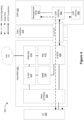
- Figure 6 is a swim lane diagram of a process flow for instantiating a tunnel and routing a data flow through said tunnel in accordance with some implementations. While pertinent features are shown, those of ordinary skill in the art will appreciate from the present disclosure that various other features have not been illustrated for the sake of brevity and so as not to obscure more pertinent aspects of the example implementations disclosed herein. To that end, as a non-limiting example, the method 600 is associated with a host-client environment (e.g., the host-client environment 400 in Figure 4 , or the host-client environment 500 in Figure 5 ).
- a host-client environment e.g., the host-client environment 400 in Figure 4 , or the host-client environment 500 in Figure 5 .
- the method 600 is performed at least in part by: a UE 602a (e.g., the UE 102 in Figures 5 or 6 ); a gateway node 602b (e.g., the Q-SGW 404 in Figure 4 , or the host gateway 504 in Figure 5 ); and a guest service provider (GSP) 602c (e.g., the GSP 420 in Figure 4 , or the GSP 520 in Figure 5 ).
- GSP guest service provider
- the UE 602a transmits (604) a request for service to the GSP 602c.
- the service corresponds to the GSP service 426 in Figure 4 or the GSP service 526 in Figure 5 .
- the request for service is transmitted from the UE 102, across the data interface 410, and received at the GSP gateway 424 within the GSP 420.
- the request for service is transmitted from the UE 102, across the data interface 410, and received at the GSP gateway 524 within the GSP 520.
- the GSP 602c transmits (606) a tunnel request to the gateway node 602b.
- the tunnel request corresponds to a request to instantiate a tunnel (e.g., the tunnel 412 in Figures 4-5 ) for a data flow from the GSP 602c to the UE 602a that traverses the operator network (e.g., the host MNO 402 in Figure 4 , or the host MNO 502 in Figure 5 ).
- the gateway node 602b determines (608) whether the tunnel request satisfies tunneling criteria.
- the QSGW 404 is communicatively coupled to the MME 208 to determine whether the tunnel request satisfies the tunneling criteria.
- the host gateway 504 determines whether the tunnel request satisfies the tunneling criteria.
- the tunneling criteria at least includes a first criterion associated with intrinsic information associated with the operator network (e.g., the host MNO 402 in Figure 4 , or the host MNO 502 in Figure 5 ) and a second criterion associated with extrinsic information that quantitatively characterizes network resources of the operator network allocated to the GSP 602c based on a predefined relationship between the operator network and the GSP 602c.
- the predefined relationship corresponds to a service level agreement (SLA) between the operator network and the GSP 602c.
- SLA service level agreement
- the intrinsic information associated with the operator network correspond to a characterization of network resources, including available network resources, reserved/used network resources, total capability of the network resources, and/or the like. In some implementations, the intrinsic information associated with the operator network correspond to at least one of: spectral usage within at least a portion of the operator network, bandwidth usage within at least a portion of the operator network, or proximity of the UE 602a to an access node within the operator network that services the UE 602a. In one example, the spectral usage corresponds to at least one of an overall spectral usage value of the operator network or a spectral usage value associated with a particular access node within the operator network that services the UE 602a.
- the access node corresponds to one of a microcell, an access point, a base station, or the like.
- the bandwidth usage corresponds to at least one of the overall bandwidth usage of the operator network or the bandwidth usage of the access node within the operator network that services the UE 602a.
- the extrinsic information correspond to at least one of: a usage allotment associated with the predefined relationship between the operator network and the GSP 602c, a bandwidth allotment associated with the predefined relationship between the operator network and the GSP 602c, a latency criterion associated with the predefined relationship between the operator network and the GSP 602c, or a QoS criterion associated with the predefined relationship between the operator network and the GSP 602c.
- the usage allotment associated with the predefined relationship between the operator network and the GSP 602c correspond to an allotment of resources, including a number of minutes available/used, a number of text messages available/used, and/or the like.
- the intrinsic information associated with the operator network and the extrinsic information associated with the operator network are stored in a policy server (e.g., the MME 208 in Figure 4 , or the AMF 306 in Figure 5 ).
- a policy server e.g., the MME 208 in Figure 4 , or the AMF 306 in Figure 5 .
- step 610a If the tunnel request does not satisfy the tunneling criteria, the process 600 continues to step 610a. If the tunnel request satisfies the tunneling criteria, the process 600 continues to step 610b.
- the gateway node 602b transmits (610a) a tunnel rejection message to the GSP 602c, in response to determining that the tunnel request does not satisfy the tunneling criteria.
- the rejection message includes a message with the reason/cause for the rejection to the GSP 602c. Further, in some implementations, the tunnel is not instantiated.
- the gateway node 602b transmits (610b) a tunnel approval message to the GSP 602c, in response to determining that the tunnel request satisfies the tunneling criteria.
- the approval message includes a message acknowledging the approval (e.g., ACK), a tunnel identifier, port information, GTP information, and/or the like.
- the gateway node 602b instantiates (612) the tunnel for the data flow between the operator network and the GSP 602c in response to determining that the request satisfies the tunneling criteria.
- the gateway node 602b also transmits tunnel instructions to other nodes of the operator network.
- the tunnel instructions include an instruction to forward the data flow to specified ports.
- the tunnel instructions include an instruction to remove a GTP tunnel header (e.g., an addressing identifier or a forwarding identifier), one or more transport labels, and/or the like.
- the GSP 602c routes (614) a data flow through the tunnel to the UE 602a.
- routing the data flow through the tunnel corresponds to the operator network transmitting the data flow to the UE 602a via one of an LTE mobile access network or a 5G mobile access network.
- FIG 7 is a simplified flowchart representation of a method 700 of instantiating a tunnel in accordance with some implementations.
- the method 700 is performed at a gateway node (e.g., the Q-SGW 404 in Figure 4 , or the host gateway 504 in Figure 5 ). While pertinent features are shown, those of ordinary skill in the art will appreciate from the present disclosure that various other features have not been illustrated for the sake of brevity and so as not to obscure more pertinent aspects of the example implementations disclosed herein.
- the method 700 includes: obtaining a tunnel request to instantiate a tunnel to route data between an GSP and a UE; determining whether the tunnel request is associated with an entity inside or outside of the MNO and determining if the tunnel request satisfies tunneling criteria; and instantiating the tunnel between the GSP and the MNO in response to determining that the tunnel request is associated with an entity outside of the MNO (e.g., the GSP) and in response to determining that the tunnel request satisfies the tunneling criteria.
- the method 700 includes obtaining a tunnel request to instantiate a tunnel to route data between an GSP and a UE.
- the tunnel request corresponds to a request to instantiate a tunnel (e.g., the tunnel 412 in Figures 4-5 ) for a data flow from the intermediary client service (e.g., the GSP 420 in Figure 4 , or the GSP 520 in Figure 5 ) that traverses the operator network (e.g., the host MNO 402 in Figure 4 , or the host MNO 502 in Figure 5 ).
- the intermediary client service e.g., the GSP 420 in Figure 4 , or the GSP 520 in Figure 5
- the operator network e.g., the host MNO 402 in Figure 4 , or the host MNO 502 in Figure 5 .
- the method 700 includes determining whether the tunnel request is associated with an entity inside or outside of the MNO. For example, with reference to Figure 6 , the gateway node 602b obtains a tunnel request with respect to step 606.
- the method 700 in response to determining that the tunnel request is associated with an entity inside of the MNO, the method 700 continues to step 706a. According to some implementations, in response to determining that the tunnel request is associated with an entity outside of the MNO, the method 700 continues to step 708.
- the method 700 includes instantiating the tunnel, in response to determining that the tunnel request is associated with an entity inside the MNO.
- the gateway node 602b instantiates the tunnel for the data flow between the operator network and the GSP 602c with respect to step 612.
- the method 700 includes determining if the tunnel request satisfies tunneling criteria, in response to determining that the tunnel request is associated with an entity outside the MNO.
- the tunneling criteria at least includes a first criterion associated with intrinsic information associated with the operator network (e.g., the host MNO 402 in Figure 4 or the host MNO 502 in Figure 5 ) and a second criterion associated with extrinsic information that quantitatively characterizes network resources of the operator network allocated to the GSP (e.g., the GSP 420 in Figure 4 , or the GSP 520 in Figure 5 ) based on a predefined relationship between the operator network and the GSP.
- the predefined relationship corresponds to a service level agreement (SLA) between the operator network and the GSP.
- SLA service level agreement
- the intrinsic information associated with the operator network correspond to at least one of: spectral usage within at least a portion of the operator network, bandwidth usage within at least a portion of the operator network, or proximity of a UE to an access node within the operator network that services the UE.
- the spectral usage corresponds to at least one of an overall spectral usage value of the operator network or the spectral usage value associated with a particular access node within the operator network that services the UE.
- the access node corresponds to one of a microcell, an access point, a base station, or the like.
- the bandwidth usage corresponds to at least one of the overall bandwidth usage of the operator network or the bandwidth usage of the access node within the operator network that services the UE.
- the intrinsic information associated with the operator network correspond to a characterization of network resources, including available network resources, reserved/used network resources, total capability of the network resources, and/or the like.
- the extrinsic information correspond to at least one of: a usage allotment associated with the predefined relationship between the operator network and the GSP (e.g., the GSP 420 in Figure 4 , or the GSP 520 in Figure 5 ), a bandwidth allotment associated with the predefined relationship between the operator network and the GSP, a latency criterion associated with the predefined relationship between the operator network and the GSP, or a QoS criterion associated with the predefined relationship between the operator network and the GSP.
- the usage allotment associated with the predefined relationship between the operator network and the GSP correspond to an allotment of resources, including a number of minutes available/used, a number of text messages available/used, and/or the like.
- the method 700 in response to determining that the tunnel request does not satisfy the tunneling criteria, the method 700 continues to step 710. According to some implementations, in response to determining that the tunnel request satisfies the tunneling criteria, the method 700 continues to step 706b.
- the method 700 includes instantiating the tunnel, in response to determining that the tunnel request satisfies the tunneling criteria.
- the gateway node 602b transmits a tunnel approval message to the GSP 602c, in response to determining that the tunnel request satisfies the tunneling criteria with respect to step 610b.
- the gateway node 602b instantiates the tunnel for the data flow between the operator network and the GSP 602c with respect to step 612, in response to determining that the request satisfies the tunneling criteria.
- the gateway node 602b also transmits tunnel instructions to other nodes of the operator network.
- the tunnel instructions include an instruction to forward the data flow to specified ports.
- the tunnel instructions include an instruction to remove a GTP tunnel header (e.g., an addressing identifier or a forwarding identifier), one or more transport labels, and/or the like.
- the method 700 includes transmitting a rejection message to the GSP, in response to determining that the tunnel request does not satisfy the tunneling criteria.
- the gateway node 602b transmits a tunnel rejection message to the GSP 602c with respect to step 610a, in response to determining that the tunnel request does not satisfy the tunneling criteria.
- the rejection message includes a message with the reason/cause for the rejection to the GSP 602c. Further, in some implementations, the tunnel is not instantiated.
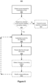
- FIG 8 is a flowchart representation of a method 800 of instantiating a tunnel and routing a data flow in accordance with some implementations.
- the method 800 is performed at a gateway node (e.g., the Q-SGW 404 in Figure 4 or the host gateway 504 in Figure 5 ). While pertinent features are shown, those of ordinary skill in the art will appreciate from the present disclosure that various other features have not been illustrated for the sake of brevity and so as not to obscure more pertinent aspects of the example implementations disclosed herein.
- the method 800 includes: obtaining a tunnel request to instantiate a tunnel; determining if the tunnel request satisfies tunneling criteria; in response to determining that the tunnel request satisfies the tunneling criteria, instantiating the tunnel for a data flow; and routing the data flow through the tunnel.
- the method 800 includes obtaining a tunnel request associated with a guest service provider to instantiate a tunnel.
- the GSP 602c transmits a tunnel request to the gateway node 602b with respect to step 606.
- the tunnel request corresponds to a request to instantiate a tunnel (e.g., the tunnel 412 in Figures 4-5 ) for a data flow from the GSP 602c to the UE 602a.
- the method 800 includes determining if the tunnel request satisfies tunneling criteria.
- the tunneling criteria at least includes a first criterion associated with intrinsic information associated with the operator network (e.g., the host MNO 402 in Figure 4 or the host MNO 502 in Figure 5 ) and a second criterion associated with extrinsic information that quantitatively characterizes network resources of the operator network allocated to the GSP (e.g., the GSP 420 in Figure 4 , or the GSP 520 in Figure 5 ) based on a predefined relationship between the operator network and the GSP.
- the predefined relationship corresponds to a service level agreement (SLA) between the operator network and the GSP.
- SLA service level agreement
- the intrinsic information associated with the operator network correspond to at least one of: spectral usage within at least a portion of the operator network, bandwidth usage within at least a portion of the operator network, or proximity of a UE to an access node within the operator network that services the UE.
- the spectral usage corresponds to at least one of an overall spectral usage value of the operator network or the spectral usage value associated with a particular access node within the operator network that services the UE.
- the access node corresponds to one of a microcell, an access point, a base station, or the like.
- the bandwidth usage corresponds to at least one of the overall bandwidth usage of the operator network or the bandwidth usage of the access node within the operator network that services the UE.
- the intrinsic information associated with the operator network correspond to a characterization of network resources, including available network resources, reserved/used network resources, total capability of the network resources, and/or the like.
- the extrinsic information correspond to at least one of: a usage allotment associated with the predefined relationship between the operator network and the GSP (e.g., the GSP 420 in Figure 4 , or the GSP 520 in Figure 5 ), a bandwidth allotment associated with the predefined relationship between the operator network and the GSP, a latency criterion associated with the predefined relationship between the operator network and the GSP, or a QoS criterion associated with the predefined relationship between the operator network and the GSP.
- the usage allotment associated with the predefined relationship between the operator network and the GSP correspond to an allotment of resources, including a number of minutes available/used, a number of text messages available/used, and/or the like.
- the method 800 in response to determining that the tunnel request satisfies the tunneling criteria, continues to step 806. According to some implementations, in response to determining that the tunnel request does not satisfy the tunneling criteria, the method 800 continues to step 814.
- the method 800 includes instantiating the tunnel, in response to determining that the tunnel request satisfies the tunneling criteria.
- the gateway node 602b transmits a tunnel approval message to the GSP 602c with respect to step 610b, in response to determining that the tunnel request satisfies the tunneling criteria.
- the gateway 602b instantiates the tunnel for the data flow between the operator network and the GSP 602c with respect to step 612, in response to determining that the request satisfies the tunneling criteria.
- the gateway node 602b also transmits tunnel instructions to other nodes of the operator network.
- the tunnel instructions include an instruction to forward the data flow to specified ports.
- the tunnel instructions include an instruction to remove a GTP tunnel header (e.g., an addressing identifier or a forwarding identifier), one or more transport labels, and/or the like.
- the method 800 includes routing the data flow through the tunnel.
- the GSP 602c routes a data flow through the tunnel to the UE 602a with respect to step 614.
- routing the data flow through the tunnel corresponds to the operator network transmitting the data flow to the UE 602a via one of an LTE mobile access network or a 5G mobile access network.
- the method 800 optionally includes detecting a change in the tunneling criteria.
- the gateway node e.g., the Q-SGW 404 in Figure 4 , or the host gateway 504 in Figure 5
- the gateway node monitors the intrinsic information associated with the operator network in order to dynamically change the tunnel and/or its attributes in response to changes to the intrinsic information.
- the changes to the intrinsic information includes one of an increased distance between the UE and the access node, an increased spectral usage, an increased bandwidth usage, or the like.
- the tunnel attributes correspond to a tunnel bandwidth, a tunnel encryption scheme, a tunnel protocol, one or more ports, and/or the like.
- the gateway node e.g., the Q-SGW 404 in Figure 4 , or the host gateway 504 in Figure 5
- the gateway node also monitors the extrinsic information associated with the predefined relationship between the operator network and the guest service provider in order to dynamically change the tunnel and/or its attributes in response to changes to the extrinsic information.
- the changes to the extrinsic information includes one of approaching a usage allotment, approaching a bandwidth allotment, or the like.
- the method 800 optionally includes modifying one or more tunnel attributes of the tunnel for the data flow in response to detecting a change to at least one of the intrinsic information or the extrinsic information.
- modifying the one or more tunnel attributes includes changing to a different tunnel protocol (e.g., a GTP connection, a Gateway-to-Gateway Protocol connection, an IP version 6 (IPv6) connection, or the like).
- IPv6 IP version 6
- the method 800 includes transmitting a rejection message to the GSP, in response to determining that the tunnel request does not satisfy the tunneling criteria.
- the gateway node 602b transmits a tunnel rejection message to the GSP 602c, in response to determining that the tunnel request does not satisfy the tunneling criteria.
- the rejection message includes a message with the reason/cause for the rejection to the GSP 602c. Further, in some implementations, the tunnel is not instantiated.
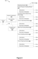
- FIG. 9 is a block diagram of an example device 900 in accordance with some implementations. While certain specific features are illustrated, those skilled in the art will appreciate from the present disclosure that various other features have not been illustrated for the sake of brevity, and so as not to obscure more pertinent aspects of the implementations disclosed herein.
- the device 900 corresponds to a gateway node, such as the gateway node 114 in Figure 1 , the Q-SGW 404 in Figure 4 , or the host gateway 504 in Figure 5
- the device 900 includes one or more processing units (CPUs) 902, one or more network interfaces 903, one or more programming interface 905, a memory 910, and one or more communication buses 904 for interconnecting these and various other components.
- CPUs processing units
- network interfaces 903 one or more programming interface 905
- memory 910 a memory 910
- communication buses 904 for interconnecting these and various other components.
- the one or more communication buses 904 include circuitry that interconnects and controls communications between system components.
- the one or more network interfaces 903 includes one or more data interfaces 903a for obtaining (e.g., receiving and/or retrieving) data flows.
- the memory 910 includes high-speed random-access memory, such as DRAM, SRAM, DDR RAM, or other random access solid state memory devices.
- the memory 910 includes non-volatile memory, such as one or more magnetic disk storage devices, optical disk storage devices, flash memory devices, or other non-volatile solid-state storage devices.
- the memory 910 optionally includes one or more storage devices remotely located from the one or more CPUs 902.
- the memory 910 comprises a non-transitory computer readable storage medium.
- the memory 910 or the non-transitory computer readable storage medium of the memory 910 stores the following programs, modules and data structures, or a subset thereof including an optional operating system 920, a tunnel request handling module 930, a tunneling criteria determining module 932, a tunnel instantiating module 934, a data flow routing module 936, a tunnel modifying module 938, and a tunnel rejecting module 940.
- the operating system 920 includes procedures for handling various basic system services and for performing hardware dependent tasks.
- the tunnel request handling module 930 is configured to obtain a tunnel request (e.g., the Q-SGW 404 in Figure 4 , or the host gateway 504 in Figure 5 ). To that end, in various implementations, the tunnel request handling module 930 includes instructions and/or logic 931a, and heuristics and metadata 931b.
- the tunneling criteria determining module 932 is configured to determine if the tunnel request satisfies tunneling criteria.
- the MME 208 inspects the tunnel request to determine whether the tunnel request satisfies the tunneling criteria.
- the AMF 306 determines whether the tunnel request satisfies the tunneling criteria.
- the tunneling criteria determining module 932 includes instructions and/or logic 933a, and heuristics and metadata 933b.
- the tunnel instantiating module 934 is configured to instantiate the tunnel for the data flow in response to determining that the tunnel request satisfies the tunneling criteria. To that end, in various implementations, the tunnel instantiating module 934 includes instructions and/or logic 935a, and heuristics and metadata 935b.
- the data flow routing module 936 is configured to route the data flow through the tunnel instantiated by the tunnel instantiating module 934. To that end, in various implementations, the data flow routing module 936 includes instructions and/or logic 937a, and heuristics and metadata 937b.
- the tunnel modifying module 938 is configured to modify one or more tunnel attributes of the tunnel for the data flow in response to detecting a change to at least one of the intrinsic information or the extrinsic information.
- the tunnel modifying module 938 includes instructions and/or logic 939a, and heuristics and metadata 939b.
- the tunnel rejecting module 940 is configured to transmit a tunnel rejection message in response to determining that the tunnel request does not satisfy the tunneling criteria.
- the tunnel rejecting module corresponds to the Q-SGW 404 in Figure 4 , the host gateway 504 in Figure 5 , or the gateway node 602b in Figure 6 .
- the tunnel rejecting module 940 includes instructions and/or logic 941a, and heuristics and metadata 941b.
- tunnel request handling module 930 the tunnel criteria determining module 932, the tunnel instantiating module 934, the data flow routing module 936, the tunnel modifying module 938, and the tunnel rejecting module 940 are shown as residing on a single device (e.g., the device 900), it should be understood that in other implementations, any combination of the tunnel request handling module 930, the tunnel criteria determining module 932, the tunnel instantiating module 934, the data flow routing module 936, the tunnel modifying module 938, and the tunnel rejecting module 940 reside in separate computing devices.
- Figure 9 is intended more as functional description of the various features which be present in a particular implementation as opposed to a structural schematic of the implementations described herein.
- items shown separately could be combined and some items could be separated .
- some functional modules shown separately in Figure 9 could be implemented in a single module and the various functions of single functional blocks could be implemented by one or more functional blocks in various implementations.
- the actual number of modules and the division of particular functions and how features are allocated among them will vary from one implementation to another and, in some implementations, depends in part on the particular combination of hardware, software, and/or firmware chosen for a particular implementation.
- first means “first,” “second,” etc.
- these elements should not be limited by these terms. These terms are only used to distinguish one element from another.
- a first node could be termed a second node, and, similarly, a second node could be termed a first node, which changing the meaning of the description, so long as all occurrences of the "first node” are renamed consistently and all occurrences of the "second node” are renamed consistently.
- the first node and the second node are both nodes, but they are not the same node.
- the term “if' may be construed to mean “when” or “upon” or “in response to determining” or “in accordance with a determination” or “in response to detecting,” that a stated condition precedent is true, depending on the context.
- the phrase “if it is determined [that a stated condition precedent is true]” or “if [a stated condition precedent is true]” or “when [a stated condition precedent is true]” may be construed to mean “upon determining” or “in response to determining” or “in accordance with a determination” or “upon detecting” or “in response to detecting” that the stated condition precedent is true, depending on the context.
Landscapes
- Engineering & Computer Science (AREA)
- Computer Networks & Wireless Communication (AREA)
- Signal Processing (AREA)
- Environmental & Geological Engineering (AREA)
- Mobile Radio Communication Systems (AREA)
- Data Exchanges In Wide-Area Networks (AREA)
Abstract
Description
- The present disclosure generally relates to content delivery, and in particular, to systems, methods, and devices for quality of service regulation.
- Mobile network operators (MNOs) manage wireless communications services for end user subscribers. Such services include, but are not limited to, radio spectrum allocation, wireless network infrastructure, and Quality of Service (QoS) parameters. On the other hand, guest service providers (GSPs), for example, do not have access to certain radio spectrum resources or have a complete infrastructure in place.
- As such, the MNOs supplement GSPs so that the GSPs are able to provide their own wireless communications services. Typically, QoS has been under-managed and under-utilized by MNOs due to a lack of policy management enforcement tools necessary to accommodate GSPs such as mobile virtual network operators (MVNOs), enterprises, application providers, roaming partner service providers, or the like.
- Additionally, MNOs share active and passive radio access system infrastructure such as base stations and network gateways. With several MNOs vying for use of the existing infrastructure, radio frequency (RF) resources are easily abused in a host MNO by demanding more RF resources than allowed.
- So that the present disclosure can be understood by those of ordinary skill in the art, a more detailed description may be had by reference to aspects of some illustrative implementations, some of which are shown in the accompanying drawings.
-
Figure 1 is a block diagram of an example data delivery environment in accordance with some implementations. -
Figure 2 is a block diagram of an example operator network in accordance with some implementations. -
Figure 3 is a block diagram of an example operator network in accordance with some implementations. -
Figure 4 is a block diagram of a host-client environment in accordance with some implementations. -
Figure 5 is a block diagram of a host-client environment in accordance with some implementations. -
Figure 6 is a swim lane diagram of a process flow for instantiating a tunnel and routing a data flow through said tunnel in accordance with some implementations. -
Figure 7 is a simplified flowchart representation of a method of instantiating a tunnel in accordance with some implementations. -
Figure 8 is a flowchart representation of a method of instantiating a tunnel and routing a data flow through said tunnel in accordance with some implementations. -
Figure 9 is a block diagram of an example device in accordance with some implementations. - In accordance with common practice the various features illustrated in the drawings may not be drawn to scale. Accordingly, the dimensions of the various features may be arbitrarily expanded or reduced for clarity. In addition, some of the drawings may not depict all of the components of a given system, method or device. Finally, like reference numerals may be used to denote like features throughout the specification and figures.
- Numerous details are described in order to provide a thorough understanding of the example implementations shown in the drawings. However, the drawings merely show some example aspects of the present disclosure and are therefore not to be considered limiting. Those of ordinary skill in the art will appreciate that other effective aspects and/or variants do not include all of the specific details described herein. Moreover, well-known systems, methods, components, devices and circuits have not been described in exhaustive detail so as not to obscure more pertinent aspects of the example implementations described herein.
- Various implementations disclosed herein include devices, systems, and methods for QoS regulation. For example, in some implementations, a method is performed at a gateway node with one or more processors, non-transitory memory, and a data interface. The method includes obtaining a request to instantiate a tunnel for a data flow from a guest service provider to a user device that traverses an operator network. The method also includes determining whether the request satisfies tunneling criteria, where the tunneling criteria at least includes a first criterion associated with intrinsic information associated with the operator network and a second criterion associated with extrinsic information that quantitatively characterizes network resources of the network operator allocated to the guest service provider based on a predefined relationship between the operator network and the guest service provider. The method further includes instantiating the tunnel for the data flow between the operator network and the guest service provider in response to determining that the request satisfies the tunneling criteria, where instantiating the tunnel for the data flow includes the gateway node transmitting tunnel instructions to other nodes of the operator network. The method further includes routing the data flow through the tunnel in order to transmit the data flow to the user device.
- In accordance with some implementations, a device includes one or more processors, a non-transitory memory, and one or more programs; the one or more programs are stored in the non-transitory memory and configured to be executed by the one or more processors and the one or more programs include instructions for performing or causing performance of any of the methods described herein. In accordance with some implementations, a non-transitory computer readable storage medium has stored therein instructions, which, when executed by one or more processors of a device, cause the device to perform or cause performance of any of the methods described herein. In accordance with some implementations, a device includes: one or more processors, a non-transitory memory, and means for performing or causing performance of any of the methods described herein.
- QoS associated with MNOs has been under-managed and under-utilized by guest service providers (GSPs) due to lack of policy management enforcement tools necessary to accommodate mobile virtual network operators (MVNOs), enterprises, application providers, roaming partner service providers, or the like.
- This invention deals with the MNO's ability to manage and process QoS requests to its radio access network (RAN) from application and service partners who are not part of the MNO's internal trusted application set. The invention safely allows an GSP to control radio frequency (RF) resources (e.g., spectral usage) in a host network by introducing a QoS-regulator feature in the host network that acts as a gatekeeper/policy enforcer for QoS requests. Implementations of a proposed solution described herein include devices, systems, and methods for QoS regulation.
-
Figure 1 is a block diagram of an exampledata delivery environment 100 in accordance with some implementations. While pertinent features are shown, those of ordinary skill in the art will appreciate from the present disclosure that various other features have not been illustrated for the sake of brevity and so as not to obscure more pertinent aspects of the example implementations disclosed herein. To that end, as a non-limiting example, thedata delivery environment 100 includes anoperator network 104 that receives and transmits data between user equipment (UE) 102 and a guest service provider (GSP) 116. In some implementations, theoperator network 104 also receives data from and transmits data to one or moreexternal networks 118. - In some implementations, the UE 102 includes a suitable combination of hardware (physical or virtualized), software, and/or firmware. As will be appreciated by one of ordinary skill in the art, although
Figure 1 depicts one UE 102, thedata delivery environment 100 includes an arbitrary number of UEs in various other implementations. For example, the UE 102 corresponds to a desktop computer, laptop computer, mobile phone, tablet, wearable computing device, set-top box (STB), over-the-top (OTT) box, gaming console, or the like. - In some implementations, the
operator network 104 includes one or more access networks (ANs) 106, acore network 110, one or moreoperator network services 112, and agateway regulator node 114. In some implementations, theoperator network 104 optionally includes anaggregation network 108. In some implementations, theoperator network 104 corresponds to a telecommunications service provider that provides wireless communication functionalities to a user/subscriber associated with the UE 102 such as a mobile network operator (MNO) that provides mobile access to content and communications. In some implementations, theoperator network 104 corresponds more generally to a service provider (SP) that provides mobile access, fixed access, satellite access, or the like to content and communications. - In some implementations, the
operator network 104 also receives and transmits data to one or moreexternal networks 118, which optionally includes receiving data from and transmitting data to the Internet, content delivery network (CDN) servers, application servers, or the like. - In some implementations, at least one of the one or more ANs 106 implements radio access technology to provide connectivity via wireless communication to the UE 102 communicatively connected to the
operator network 104. In one example, at least one of the one ormore ANs 106 corresponds to a Long-Term Evolution (LTE) mobile access network (sometimes also referred to as 4G) that includes evolved node B (eNodeB) access nodes and the like. In another example, at least one of the one ormore ANs 106 correspond to a 5G mobile access network that includes 5G base stations and the like. - In some implementations, at least one of the one or more ANs 106 implements non-radio access technology to provide connectivity via wired or wireless communication to the UE 102 communicatively connected to the
operator network 104. For example, the non-radio access technology includes an IEEE 802.11x Wi-Fi network, a fiber optic network, an IEEE 802.3x Ethernet network, or the like. - In some implementations, at least one of the one or
more ANs 106 implements heterogeneous access technology via wired or wireless communication to the UE 102 communicatively connected to theoperator network 104. For example, the heterogeneous access technology includes a combination of radio access and non-radio access technologies. - In some implementations, the
core network 110 provides internet protocol (IP) routing and forwarding for a data flow between end points. For example, the end points include the one or moreoperator network services 112, the one or moreexternal networks 118, thegateway regulator node 114, or the like. - In some implementations, the one or more
operator network services 112 include wireless communication services to control the elements of theoperator network 104 in order to monitor and deliver services to an end user (e.g., the UE 102). As one example, the one or moreoperator network services 112 optionally include radio spectrum allocation management, infrastructure and networking management, QoS policy enforcement, billing services, customer support services, security auditing services, infrastructure and networking maintenance, and/or the like. In another example, the one or moreoperator network services 112 include content delivery services such as an IP multimedia subsystem (IMS). In yet another example, the one or moreoperator network services 112 include communication services such as voice-over Long-Term Evolution (VoLTE) or voice-over Internet Protocol (VoIP). - In some implementations, the
aggregation network 108 combines multiple network connections in parallel to increase throughput and to provide redundancies in case one of the network connections should fail. - In some implementations, the
operator network 104 includes thegateway regulator node 114 that serves as an interface node between theoperator network 104 and theguest service provider 116. In some implementations, thegateway regulator node 114 includes a suitable combination of hardware (physical or virtualized), software, and/or firmware to maintain communication protocols between theoperator network 104 and theguest service provider 116. For example, thegateway regulator node 114 is configured to translate and map gateway interconnects for networks with different protocol technologies by performing protocol conversions. Further, in another example, the networks with different protocol technologies include theoperator network 104 and theguest service provider 116. - In some implementations, the
guest service provider 116 corresponds to one of anMVNO 118, anenterprise 120, an applications/OTT provider 122, one or moreroaming partner SPs 124, or the like. In some implementations, theguest service provider 116 is not affiliated with theoperator network 104. In one example, theguest service provider 116 does not include policy management. - For example, the
MVNO 118 corresponds to a telecommunications service provider that has an agreement with theoperator network 104 to provide its subscribers with telecommunications capabilities using the infrastructure of theoperator network 104. For example, theenterprise 120 corresponds to a telecommunications service provider that provides consulting, system integration, software development, outsourcing and/or the like. For example, the applications/OTT provider 122 corresponds to a telecommunications service provider that delivers one or more services across an IP network without requiring its users to subscribe to a traditional service provider. For example, the one or moreroaming partner SPs 124 correspond to one or more telecommunications service providers that have cooperative agreements to grant subscribers local access to the network. -
Figure 2 is a block diagram of anexample operator network 200 in accordance with some implementations. While pertinent features are shown, those of ordinary skill in the art will appreciate from the present disclosure that various other features have not been illustrated for the sake of brevity and so as not to obscure more pertinent aspects of the example implementations disclosed herein. To that end, as a non-limiting example, theoperator network 200 corresponds to an operator network with a long-term evolution (LTE) architecture, sometimes simply called a 4G architecture. Theoperator network 200 communicates with a user equipment (UE) 202 (e.g., theUE 102 ofFigure 1 ). According to some implementations, as shown inFigure 2 , theoperator network 200 includes an evolved universal mobile telecommunication system (UMTS) terrestrial radio access network (EUTRAN) 204 that includes one or more evolved node-Bs (eNodeBs) 206a, ..., 206n, a mobility management entity (MME) 208, a serving-gateway (S-GW) 210, a packet data network gateway (PDN-GW) 212, a home subscriber server (HSS) 214, and a packet data network (PDN) 216. According to some implementations, theoperator network 200 optionally includes an IP multimedia subsystem (IMS) 218. According to some implementations, theoperator network 200 also optionally includes a policy and charging rules function (PCRF) 220. - In some implementations, the
EUTRAN 204 corresponds to a RAN that includes one ormore eNodeBs 206a, ..., 206n and provides a communication pathway between theUE 202 and theMME 208 or the S-GW 210.eNodeBs 206a, ..., 206n correspond to access nodes that provide communications between theEUTRAN 204 and theUE 202. According to some implementations, theEUTRAN 204 is configured to operate similarly to one of the one or more ANs 106 inFigure 1 . - In some implementations, the
MME 208 is configured to initiate paging and authentication of the mobile device (e.g., the UE 202). TheMME 208 retains the location information for each user and selects the appropriate gateway. In some implementations, theMME 208 connects with a respective one of the one ormore eNodeBs 206a, ..., 206n. Further, in some implementations, theMME 208 also communicates with theHSS 214 which serves as a master user database that supports the IMS network entities that handle calls and sessions. - In some implementations, the
EUTRAN 204 communicates with the S-GW 210 and sends packets of data (e.g., video, audio, and/or the like) through the S-GW 210 to the PDN-GW 212. Further, in some implementations, the PDN-GW 212 is configured to be the point of interconnect between the external IP networks (e.g., the PDN 216) and routes packets of data to and from the PDN 216. In some implementations, the S-GW 210 communicates with theMME 208 to access user information to determine the appropriate gateway to transmit packets of data. As will be appreciated by one of ordinary skill in the art, althoughFigure 2 depicts one PDN 216, theoperator network 200 includes an arbitrary number of PDNs in various other implementations. In some implementations, the PDN-GW 212 optionally communicates withIMS 218 andPCRF 220 - In some implementations, the
operator network 200 optionally includes theIMS 218 which is configured to control and deliver multimedia communications (e.g., video, audio, messages, and/or the like) across a data network. - In some implementations, the
operator network 200 optionally includes thePCRF 220 which manages policy decisions and operator-defined charging rules associated with the data flow. For example, policy decisions and charging rules are based at least in part by QoS setting information for a user session, data flow detection, policy enforcement, flow-based charging, and/or the like. -
Figure 3 is a block diagram of anexample operator network 300 in accordance with some implementations. While pertinent features are shown, those of ordinary skill in the art will appreciate from the present disclosure that various other features have not been illustrated for the sake of brevity and so as not to obscure more pertinent aspects of the example implementations disclosed herein. To that end, as a non-limiting example, theoperator network 300 corresponds to an operator network with a 5G architecture. According to some implementations, as shown inFigure 3 , theoperator network 300 includes a user equipment (UE) (e.g., theUE 102 inFigure 1 ), an authentication server function (AUSF)module 302, a unified data management (UDM)module 304, a core access and mobility management function (AMF)module 306, a session management function (SMF)module 308, a policy control function (PCF)module 310, anapplication function module 312, aRAN 314, a user plane function (UPF)module 316, and adata network 318. - In some implementations, the
AUSF 302 is configured to facilitate authentication of an entity that attempts to access a network. As shown inFigure 3 , theAUSF 302 is communicatively coupled to theUDM 304 and theAMF 306. For example, theAUSF 302 is configured to perform security and privacy processes, such as data isolation between network slices, encryption/decryption, and/or the like. - In some implementations, the
UDM 304 is configured to create a unified development and delivery environment that provides theUE 102 with access to consistent, accurate, and timely data. As shown inFigure 3 , theUDM 304 is communicatively coupled to theAUSF 302, theAMF 306, and theSMF 308. - In some implementations, the
AMF 306 is configured to initiate paging and authentication of the mobile device (e.g., the UE 102). As shown inFigure 3 , theAMF 306 is communicatively coupled to theUE 102, theRAN 314, theAUSF 302, and theUDM 304. In some implementations, theAMF 306 is a user-plane function that includes mobile management capabilities. For example, theAMF 306 is configured to operate similarly to theMME 208 inFigure 2 . - In some implementations, the
SMF 308 is configured to provide users/subscribers an option to save and restore sessions . As shown inFigure 3 , theSMF 308 is communicatively coupled to theUDM 304, theAMF 306, thePCF 310, and theUPF 316. For example, theSMF 308 is configured to save and restore one or more initial states associated with one or more applications. Further, for example, the initial states include the name of an open file, a displayed image, a video in progress, and/or the like. - In some implementations, the
PCF 310 is configured to determine policy rules in a multimedia network. As shown inFigure 3 , thePCF 310 is communicatively coupled to theAMF 306, theSMF 308, and theapplication function module 312. For example, thePCF 310 designates policy in real-time via software. - In some implementations, the
application function module 312 is configured to perform quality control for specific applications operating within a network. As shown inFigure 3 , theapplication function module 312 is communicatively coupled to thePCF 310. For example, quality control corresponds to evaluating QoS related to performance - In some implementations, the
RAN 314 implements radio access technology to provide connectivity via wireless communication to theUE 102 connected to theoperator network 300. For example, theRAN 314 corresponds to a 5G mobile access network where theRAN 314 includes 5G base stations and the like. According to some implementations, theRAN 314 is configured to operate similarly to one of the one or more ANs 106 inFigure 1 . As shown inFigure 3 , theRAN 314 is communicatively coupled to theUE 102, theAMF 306, and theUPF 316. - In some implementations, the
UPF 316 is configured to carry the traffic in theoperator network 300. As shown inFigure 3 , the UPF is communicatively coupled to theRAN 314, theSMF 308, and thedata network 318. In some implementations, theUPF 316 forwards traffic to a next-hop along the path to the selected destination data network (e.g., the data network 318). In some implementations, the data plane packets are transmitted through a delivery node (e.g., a router, a switch, and/or the like). To that end, the delivery node is configured to dispose of incoming and outgoing packets. - In some implementations, the
data network 318 includes a router, switches, and/or the like. In some implementations, thedata network 318 provides IP routing and forwarding for packets between end points. For example, thedata network 318 corresponds to a portion of an operator network (e.g., thecore network 110 of theoperator network 104 inFigure 1 ). -
Figure 4 is a block diagram of a host-client environment 400 in accordance with some implementations. While pertinent features are shown, those of ordinary skill in the art will appreciate from the present disclosure that various other features have not been illustrated for the sake of brevity and so as not to obscure more pertinent aspects of the example implementations disclosed herein. Elements common toFigure 2 and4 include common reference numbers, and only the differences betweenFigures 2 and4 are described herein for the sake of brevity. To that end, as a non-limiting example, the host-client environment 400 includes aUE 102, ahost MNO 402, adata interface 410, atunnel 412, a guest service provider (GSP) 420, and a packet data network (PDN) 216. In some implementations, the host-client environment 400 utilizes an LTE mobile access network. - As shown in
Figure 4 , thehost MNO 402 includes anMNO EUTRAN 204, a serving gateway (S-GW) 210, a packet data network gateway (PDN-GW) 212, a mobility management entity (MME) 208, and a Q-serving gateway (Q-SGW) 404. In some implementations, thehost MNO 402 optionally includes an IP multimedia subsystem (IMS) 218. In one example, thehost MNO 402 corresponds to theoperator network 104 inFigure 1 or theoperator network 200 inFigure 2 . - In some implementations, the Q-
SGW 404 is configured to intercept data flows associated with QoS requests between thehost MNO 402 and theGSP 420. For example, the Q-SGW 404 is configured to serve as a gatekeeper/policy enforcement node for QoS requests at thehost MNO 402. In another example, the Q-SGW 404 inspects session requests based on information derived in theMME 208 to determine whether to instantiate thetunnel 412. - In some implementations, the
data interface 410 corresponds to an IP interconnect between access networks. For example, thedata interface 410, includes a GPRS tunneling protocol (GTP) connection, a UMTS connection, and/or the like. - In some implementations, the
tunnel 412 is instantiated across the data interface 410 to communicatively couple thehost MNO 402 and theGSP 420. For example, thetunnel 412 corresponds to an S8 Home Routed (S8HR) interface. In some implementations, thetunnel 412 is configured to carry data and control signals across thedata interface 410. In one example, thetunnel 412 is configured to carry one of a GTP connection, or the like. - In some implementations, the
GSP 420 includes amanagement node 422, anGSP gateway 424, and anGSP service 426. For example, theGSP 420 corresponds to theguest service provider 116 inFigure 1 . Further, in another example, theGSP 420 corresponds to one of anMVNO 118, anenterprise 120, an application/OTT provider 122, one ormore roaming partners 124, or the like. - In some implementations, the
management node 422 is configured to manage UE information and facilitate communications at theGSP gateway 424. For example, with reference toFigure 2 , themanagement node 422 includes the home subscriber server (HSS) 214, the policy and charging rules function (PCRF) 220, and/or the like. - In some implementations, the
GSP gateway 424 is configured to be the point of interconnect between the external IP networks within theGSP 420 and routes packets of data via thetunnel 412. - In some implementations, the
GSP service 426 corresponds to a service platform that allows theGSP 420 to manage usage and spectral resources. For example, theGSP service 426 corresponds to a VoLTE service, VoIP service, an application, or the like. In one example, with reference toFigure 1 , theGSP service 426 corresponding to theenterprise 120 includes consulting, system integration, software development, outsourcing, and/or the like. In another example, with continued reference toFigure 1 , theGSP service 426 corresponding to the application/OTT provider 122 includes wireless connectivity to user devices while accessing a cellular infrastructure from an MNO (e.g., the host MNO 402). -
Figure 5 is a block diagram of a host-client environment 500 in accordance with some implementations. While pertinent features are shown, those of ordinary skill in the art will appreciate from the present disclosure that various other features have not been illustrated for the sake of brevity and so as not to obscure more pertinent aspects of the example implementations disclosed herein. Elements common toFigures 3 ,4 , and5 include common reference numbers, and only the differences betweenFigure 3 ,4 , and5 are described herein for the sake of brevity. To that end, as a non-limiting example, the host-client environment 500 includes aUE 102, ahost MNO 502, adata interface 410, atunnel 412, and an intermediate client service provider (GSP) 520. In some implementations, the host-client environment 500 utilizes a 5G mobile access network. - As shown in
Figure 5 , thehost MNO 502 includes anAUSF 302, aUDM 304, anAMF 306, anSMF 308, aPCF 310, anapplication function 312, aRAN 314, aUPF 316, adata network 318, and ahost gateway 504. In one example, thehost MNO 502 corresponds to theoperator network 104 inFigure 1 or theoperator network 300 inFigure 3 . - In some implementations, the
host gateway 504 is configured to intercept data flows associated with QoS between thehost MNO 402 and theGSP 420. For example, thehost gateway 504 is configured to serve as a gatekeeper/policy enforcement node for QoS requests in thehost MNO 402. In another example, thehost gateway 504 inspects session requests to determine whether to instantiate thetunnel 412. In one example, thehost gateway 504 corresponds to the Q-SGW 404 inFigure 4 . - In some implementations, the
GSP 520 includes amanagement node 522, theGSP gateway 524, and anGSP service 526. For example, theGSP 520 corresponds to theguest service provider 116 inFigure 1 . Further, in another example, with reference toFigure 1 , theGSP 520 corresponds to one of anMVNO 118, anenterprise 120, an application/OTT provider 122, one ormore roaming partners 124, or the like. - In some implementations, the
management node 522 is configured to manage UE information and facilitate communications at theGSP gateway 524. For example, with reference toFigure 3 , themanagement node 522 includes the unified data management (UDM) 304, the session management function (SMF) 308, the policy control function (PCF) 310, theapplication function 312, or the like. - In some implementations, the
GSP gateway 524 is configured to be the point of interconnect between the external IP networks within theGSP 520 and routes packets of data via thetunnel 412. - In some implementations, the
GSP service 526 corresponds to a service platform that allows the GSP to manage usage and spectral resources. For example, theGSP service 526 corresponds to a VoLTE service, VoIP service, an application, or the like. In one example, with reference toFigure 1 , theGSP service 526 corresponding to theenterprise 120 includes consulting, system integration, software development, outsourcing, and/or the like. In another example, with continued reference toFigure 1 , theGSP service 526 corresponding to the application/OTT provider 122 includes wireless connectivity to user devices while accessing a cellular infrastructure from an MNO (e.g., the host MNO 502). -
Figure 6 is a swim lane diagram of a process flow for instantiating a tunnel and routing a data flow through said tunnel in accordance with some implementations. While pertinent features are shown, those of ordinary skill in the art will appreciate from the present disclosure that various other features have not been illustrated for the sake of brevity and so as not to obscure more pertinent aspects of the example implementations disclosed herein. To that end, as a non-limiting example, themethod 600 is associated with a host-client environment (e.g., the host-client environment 400 inFigure 4 , or the host-client environment 500 inFigure 5 ). In some implementations, themethod 600 is performed at least in part by: a UE 602a (e.g., theUE 102 inFigures 5 or6 ); agateway node 602b (e.g., the Q-SGW 404 inFigure 4 , or thehost gateway 504 inFigure 5 ); and a guest service provider (GSP) 602c (e.g., theGSP 420 inFigure 4 , or theGSP 520 inFigure 5 ). - In some implementations, the UE 602a transmits (604) a request for service to the
GSP 602c. For example, the service corresponds to theGSP service 426 inFigure 4 or theGSP service 526 inFigure 5 . In some implementations, with reference toFigure 4 , the request for service is transmitted from theUE 102, across thedata interface 410, and received at theGSP gateway 424 within theGSP 420. In some implementations, with reference toFigure 5 , the request for service is transmitted from theUE 102, across thedata interface 410, and received at theGSP gateway 524 within theGSP 520. - In some implementations, the
GSP 602c transmits (606) a tunnel request to thegateway node 602b. In some implementations, the tunnel request corresponds to a request to instantiate a tunnel (e.g., thetunnel 412 inFigures 4-5 ) for a data flow from theGSP 602c to the UE 602a that traverses the operator network (e.g., thehost MNO 402 inFigure 4 , or thehost MNO 502 inFigure 5 ). - In some implementations, the
gateway node 602b determines (608) whether the tunnel request satisfies tunneling criteria. In one example, with reference toFigure 4 , theQSGW 404 is communicatively coupled to theMME 208 to determine whether the tunnel request satisfies the tunneling criteria. In another example, with reference toFigure 5 , thehost gateway 504 determines whether the tunnel request satisfies the tunneling criteria. - In some implementations, the tunneling criteria at least includes a first criterion associated with intrinsic information associated with the operator network (e.g., the
host MNO 402 inFigure 4 , or thehost MNO 502 inFigure 5 ) and a second criterion associated with extrinsic information that quantitatively characterizes network resources of the operator network allocated to theGSP 602c based on a predefined relationship between the operator network and theGSP 602c. In one example, the predefined relationship corresponds to a service level agreement (SLA) between the operator network and theGSP 602c. - In some implementations, the intrinsic information associated with the operator network correspond to a characterization of network resources, including available network resources, reserved/used network resources, total capability of the network resources, and/or the like. In some implementations, the intrinsic information associated with the operator network correspond to at least one of: spectral usage within at least a portion of the operator network, bandwidth usage within at least a portion of the operator network, or proximity of the UE 602a to an access node within the operator network that services the UE 602a. In one example, the spectral usage corresponds to at least one of an overall spectral usage value of the operator network or a spectral usage value associated with a particular access node within the operator network that services the UE 602a. In another example, the access node corresponds to one of a microcell, an access point, a base station, or the like. In another example, the bandwidth usage corresponds to at least one of the overall bandwidth usage of the operator network or the bandwidth usage of the access node within the operator network that services the UE 602a.
- In some implementations, the extrinsic information correspond to at least one of: a usage allotment associated with the predefined relationship between the operator network and the
GSP 602c, a bandwidth allotment associated with the predefined relationship between the operator network and theGSP 602c, a latency criterion associated with the predefined relationship between the operator network and theGSP 602c, or a QoS criterion associated with the predefined relationship between the operator network and theGSP 602c. In one example, the usage allotment associated with the predefined relationship between the operator network and theGSP 602c correspond to an allotment of resources, including a number of minutes available/used, a number of text messages available/used, and/or the like. - In some implementations, the intrinsic information associated with the operator network and the extrinsic information associated with the operator network are stored in a policy server (e.g., the
MME 208 inFigure 4 , or theAMF 306 inFigure 5 ). - If the tunnel request does not satisfy the tunneling criteria, the
process 600 continues to step 610a. If the tunnel request satisfies the tunneling criteria, theprocess 600 continues to step 610b. - In some implementations, the
gateway node 602b transmits (610a) a tunnel rejection message to theGSP 602c, in response to determining that the tunnel request does not satisfy the tunneling criteria. In some implementations, the rejection message includes a message with the reason/cause for the rejection to theGSP 602c. Further, in some implementations, the tunnel is not instantiated. - In some implementations, the
gateway node 602b transmits (610b) a tunnel approval message to theGSP 602c, in response to determining that the tunnel request satisfies the tunneling criteria. In some implementations, the approval message includes a message acknowledging the approval (e.g., ACK), a tunnel identifier, port information, GTP information, and/or the like. - In some implementations, the
gateway node 602b instantiates (612) the tunnel for the data flow between the operator network and theGSP 602c in response to determining that the request satisfies the tunneling criteria. In some implementations, thegateway node 602b also transmits tunnel instructions to other nodes of the operator network. In one example, the tunnel instructions include an instruction to forward the data flow to specified ports. In another example, the tunnel instructions include an instruction to remove a GTP tunnel header (e.g., an addressing identifier or a forwarding identifier), one or more transport labels, and/or the like. - In some implementations, the
GSP 602c routes (614) a data flow through the tunnel to the UE 602a. In some implementations, routing the data flow through the tunnel corresponds to the operator network transmitting the data flow to the UE 602a via one of an LTE mobile access network or a 5G mobile access network. -
Figure 7 is a simplified flowchart representation of amethod 700 of instantiating a tunnel in accordance with some implementations. In various implementations, themethod 700 is performed at a gateway node (e.g., the Q-SGW 404 inFigure 4 , or thehost gateway 504 inFigure 5 ). While pertinent features are shown, those of ordinary skill in the art will appreciate from the present disclosure that various other features have not been illustrated for the sake of brevity and so as not to obscure more pertinent aspects of the example implementations disclosed herein. To that end, briefly, in some circumstances, themethod 700 includes: obtaining a tunnel request to instantiate a tunnel to route data between an GSP and a UE; determining whether the tunnel request is associated with an entity inside or outside of the MNO and determining if the tunnel request satisfies tunneling criteria; and instantiating the tunnel between the GSP and the MNO in response to determining that the tunnel request is associated with an entity outside of the MNO (e.g., the GSP) and in response to determining that the tunnel request satisfies the tunneling criteria. - In some implementations, as represented by
block 702, themethod 700 includes obtaining a tunnel request to instantiate a tunnel to route data between an GSP and a UE. For example, with reference toFigure 4 , the tunnel request corresponds to a request to instantiate a tunnel (e.g., thetunnel 412 inFigures 4-5 ) for a data flow from the intermediary client service (e.g., theGSP 420 inFigure 4 , or theGSP 520 inFigure 5 ) that traverses the operator network (e.g., thehost MNO 402 inFigure 4 , or thehost MNO 502 inFigure 5 ). - In some implementations, as represented by
block 704, themethod 700 includes determining whether the tunnel request is associated with an entity inside or outside of the MNO. For example, with reference toFigure 6 , thegateway node 602b obtains a tunnel request with respect to step 606. - According to some implementations, in response to determining that the tunnel request is associated with an entity inside of the MNO, the
method 700 continues to step 706a. According to some implementations, in response to determining that the tunnel request is associated with an entity outside of the MNO, themethod 700 continues to step 708. - In some implementations, as represented by
block 706a, themethod 700 includes instantiating the tunnel, in response to determining that the tunnel request is associated with an entity inside the MNO. For example, with reference toFigure 6 , thegateway node 602b instantiates the tunnel for the data flow between the operator network and theGSP 602c with respect to step 612. - In some implementations, as represented by
block 708, themethod 700 includes determining if the tunnel request satisfies tunneling criteria, in response to determining that the tunnel request is associated with an entity outside the MNO. In some implementations, the tunneling criteria at least includes a first criterion associated with intrinsic information associated with the operator network (e.g., thehost MNO 402 inFigure 4 or thehost MNO 502 inFigure 5 ) and a second criterion associated with extrinsic information that quantitatively characterizes network resources of the operator network allocated to the GSP (e.g., theGSP 420 inFigure 4 , or theGSP 520 inFigure 5 ) based on a predefined relationship between the operator network and the GSP. In one example, the predefined relationship corresponds to a service level agreement (SLA) between the operator network and the GSP. - In some implementations, the intrinsic information associated with the operator network correspond to at least one of: spectral usage within at least a portion of the operator network, bandwidth usage within at least a portion of the operator network, or proximity of a UE to an access node within the operator network that services the UE. In one example, the spectral usage corresponds to at least one of an overall spectral usage value of the operator network or the spectral usage value associated with a particular access node within the operator network that services the UE. In another example, the access node corresponds to one of a microcell, an access point, a base station, or the like. In another example, the bandwidth usage corresponds to at least one of the overall bandwidth usage of the operator network or the bandwidth usage of the access node within the operator network that services the UE.
- In some implementations, the intrinsic information associated with the operator network correspond to a characterization of network resources, including available network resources, reserved/used network resources, total capability of the network resources, and/or the like.
- In some implementations, the extrinsic information correspond to at least one of: a usage allotment associated with the predefined relationship between the operator network and the GSP (e.g., the
GSP 420 inFigure 4 , or theGSP 520 inFigure 5 ), a bandwidth allotment associated with the predefined relationship between the operator network and the GSP, a latency criterion associated with the predefined relationship between the operator network and the GSP, or a QoS criterion associated with the predefined relationship between the operator network and the GSP. In one example, the usage allotment associated with the predefined relationship between the operator network and the GSP correspond to an allotment of resources, including a number of minutes available/used, a number of text messages available/used, and/or the like. - According to some implementations, in response to determining that the tunnel request does not satisfy the tunneling criteria, the
method 700 continues to step 710. According to some implementations, in response to determining that the tunnel request satisfies the tunneling criteria, themethod 700 continues to step 706b. - In some implementations, as represented by
block 706b, themethod 700 includes instantiating the tunnel, in response to determining that the tunnel request satisfies the tunneling criteria. In some implementations, with reference toFigure 6 , thegateway node 602b transmits a tunnel approval message to theGSP 602c, in response to determining that the tunnel request satisfies the tunneling criteria with respect to step 610b. In some implementations, with continued reference toFigure 6 , thegateway node 602b instantiates the tunnel for the data flow between the operator network and theGSP 602c with respect to step 612, in response to determining that the request satisfies the tunneling criteria. In some implementations, thegateway node 602b also transmits tunnel instructions to other nodes of the operator network. In one example, the tunnel instructions include an instruction to forward the data flow to specified ports. In another example, the tunnel instructions include an instruction to remove a GTP tunnel header (e.g., an addressing identifier or a forwarding identifier), one or more transport labels, and/or the like. - In some implementations, as represented by
block 710, themethod 700 includes transmitting a rejection message to the GSP, in response to determining that the tunnel request does not satisfy the tunneling criteria. In some implementations, with reference toFigure 6 , thegateway node 602b transmits a tunnel rejection message to theGSP 602c with respect tostep 610a, in response to determining that the tunnel request does not satisfy the tunneling criteria. In some implementations, the rejection message includes a message with the reason/cause for the rejection to theGSP 602c. Further, in some implementations, the tunnel is not instantiated. -
Figure 8 is a flowchart representation of amethod 800 of instantiating a tunnel and routing a data flow in accordance with some implementations. In various implementations, themethod 800 is performed at a gateway node (e.g., the Q-SGW 404 inFigure 4 or thehost gateway 504 inFigure 5 ). While pertinent features are shown, those of ordinary skill in the art will appreciate from the present disclosure that various other features have not been illustrated for the sake of brevity and so as not to obscure more pertinent aspects of the example implementations disclosed herein. To that end, briefly, in some circumstances, themethod 800 includes: obtaining a tunnel request to instantiate a tunnel; determining if the tunnel request satisfies tunneling criteria; in response to determining that the tunnel request satisfies the tunneling criteria, instantiating the tunnel for a data flow; and routing the data flow through the tunnel. In some implementations, as represented byblock 802, themethod 800 includes obtaining a tunnel request associated with a guest service provider to instantiate a tunnel. For example, with reference toFigure 6 , theGSP 602c transmits a tunnel request to thegateway node 602b with respect to step 606. In some implementations, the tunnel request corresponds to a request to instantiate a tunnel (e.g., thetunnel 412 inFigures 4-5 ) for a data flow from theGSP 602c to the UE 602a. - In some implementations, as represented by
block 804, themethod 800 includes determining if the tunnel request satisfies tunneling criteria. In some implementations, the tunneling criteria at least includes a first criterion associated with intrinsic information associated with the operator network (e.g., thehost MNO 402 inFigure 4 or thehost MNO 502 inFigure 5 ) and a second criterion associated with extrinsic information that quantitatively characterizes network resources of the operator network allocated to the GSP (e.g., theGSP 420 inFigure 4 , or theGSP 520 inFigure 5 ) based on a predefined relationship between the operator network and the GSP. In one example, the predefined relationship corresponds to a service level agreement (SLA) between the operator network and the GSP. - In some implementations, the intrinsic information associated with the operator network correspond to at least one of: spectral usage within at least a portion of the operator network, bandwidth usage within at least a portion of the operator network, or proximity of a UE to an access node within the operator network that services the UE. In one example, the spectral usage corresponds to at least one of an overall spectral usage value of the operator network or the spectral usage value associated with a particular access node within the operator network that services the UE. In another example, the access node corresponds to one of a microcell, an access point, a base station, or the like. In another example, the bandwidth usage corresponds to at least one of the overall bandwidth usage of the operator network or the bandwidth usage of the access node within the operator network that services the UE.
- In some implementations, the intrinsic information associated with the operator network correspond to a characterization of network resources, including available network resources, reserved/used network resources, total capability of the network resources, and/or the like.
- In some implementations, the extrinsic information correspond to at least one of: a usage allotment associated with the predefined relationship between the operator network and the GSP (e.g., the
GSP 420 inFigure 4 , or theGSP 520 inFigure 5 ), a bandwidth allotment associated with the predefined relationship between the operator network and the GSP, a latency criterion associated with the predefined relationship between the operator network and the GSP, or a QoS criterion associated with the predefined relationship between the operator network and the GSP. In one example, the usage allotment associated with the predefined relationship between the operator network and the GSP correspond to an allotment of resources, including a number of minutes available/used, a number of text messages available/used, and/or the like. - According to some implementations, in response to determining that the tunnel request satisfies the tunneling criteria, the
method 800 continues to step 806. According to some implementations, in response to determining that the tunnel request does not satisfy the tunneling criteria, themethod 800 continues to step 814. - In some implementations, as represented by
block 806, themethod 800 includes instantiating the tunnel, in response to determining that the tunnel request satisfies the tunneling criteria. In some implementations, with reference toFigure 6 , thegateway node 602b transmits a tunnel approval message to theGSP 602c with respect tostep 610b, in response to determining that the tunnel request satisfies the tunneling criteria. In some implementations, with continued reference toFigure 6 , thegateway 602b instantiates the tunnel for the data flow between the operator network and theGSP 602c with respect to step 612, in response to determining that the request satisfies the tunneling criteria. In some implementations, thegateway node 602b also transmits tunnel instructions to other nodes of the operator network. In one example, the tunnel instructions include an instruction to forward the data flow to specified ports. In another example, the tunnel instructions include an instruction to remove a GTP tunnel header (e.g., an addressing identifier or a forwarding identifier), one or more transport labels, and/or the like. - In some implementations, as represented by
block 808, themethod 800 includes routing the data flow through the tunnel. For example, with reference toFigure 6 , theGSP 602c routes a data flow through the tunnel to the UE 602a with respect to step 614. In some implementations, routing the data flow through the tunnel corresponds to the operator network transmitting the data flow to the UE 602a via one of an LTE mobile access network or a 5G mobile access network. - In some implementations, as represented by
block 810, themethod 800 optionally includes detecting a change in the tunneling criteria. In some implementations, the gateway node (e.g., the Q-SGW 404 inFigure 4 , or thehost gateway 504 inFigure 5 ) monitors the intrinsic information associated with the operator network in order to dynamically change the tunnel and/or its attributes in response to changes to the intrinsic information. For example, the changes to the intrinsic information includes one of an increased distance between the UE and the access node, an increased spectral usage, an increased bandwidth usage, or the like. In another example, the tunnel attributes correspond to a tunnel bandwidth, a tunnel encryption scheme, a tunnel protocol, one or more ports, and/or the like. - In some implementations, the gateway node (e.g., the Q-
SGW 404 inFigure 4 , or thehost gateway 504 inFigure 5 ) also monitors the extrinsic information associated with the predefined relationship between the operator network and the guest service provider in order to dynamically change the tunnel and/or its attributes in response to changes to the extrinsic information. For example, the changes to the extrinsic information includes one of approaching a usage allotment, approaching a bandwidth allotment, or the like. - In some implementations, as represented by
block 812, themethod 800 optionally includes modifying one or more tunnel attributes of the tunnel for the data flow in response to detecting a change to at least one of the intrinsic information or the extrinsic information. For example, modifying the one or more tunnel attributes includes changing to a different tunnel protocol (e.g., a GTP connection, a Gateway-to-Gateway Protocol connection, an IP version 6 (IPv6) connection, or the like). In some implementations, once the one or more tunnel attributes are modified, themethod 800 optionally proceeds to block 806. - In some implementations, as represented by
block 814, themethod 800 includes transmitting a rejection message to the GSP, in response to determining that the tunnel request does not satisfy the tunneling criteria. In some implementations, with reference toFigure 6 , thegateway node 602b transmits a tunnel rejection message to theGSP 602c, in response to determining that the tunnel request does not satisfy the tunneling criteria. In some implementations, the rejection message includes a message with the reason/cause for the rejection to theGSP 602c. Further, in some implementations, the tunnel is not instantiated. -
Figure 9 is a block diagram of anexample device 900 in accordance with some implementations. While certain specific features are illustrated, those skilled in the art will appreciate from the present disclosure that various other features have not been illustrated for the sake of brevity, and so as not to obscure more pertinent aspects of the implementations disclosed herein. To that end, as a non-limiting example, thedevice 900 corresponds to a gateway node, such as thegateway node 114 inFigure 1 , the Q-SGW 404 inFigure 4 , or thehost gateway 504 inFigure 5 In some implementations, thedevice 900 includes one or more processing units (CPUs) 902, one ormore network interfaces 903, one ormore programming interface 905, amemory 910, and one ormore communication buses 904 for interconnecting these and various other components. - In some implementations, the one or
more communication buses 904 include circuitry that interconnects and controls communications between system components. In some implementations, the one or more network interfaces 903 includes one ormore data interfaces 903a for obtaining (e.g., receiving and/or retrieving) data flows. - The
memory 910 includes high-speed random-access memory, such as DRAM, SRAM, DDR RAM, or other random access solid state memory devices. In some implementations, thememory 910 includes non-volatile memory, such as one or more magnetic disk storage devices, optical disk storage devices, flash memory devices, or other non-volatile solid-state storage devices. Thememory 910 optionally includes one or more storage devices remotely located from the one ormore CPUs 902. Thememory 910 comprises a non-transitory computer readable storage medium. In some implementations, thememory 910 or the non-transitory computer readable storage medium of thememory 910 stores the following programs, modules and data structures, or a subset thereof including anoptional operating system 920, a tunnelrequest handling module 930, a tunnelingcriteria determining module 932, atunnel instantiating module 934, a dataflow routing module 936, atunnel modifying module 938, and atunnel rejecting module 940. - The
operating system 920 includes procedures for handling various basic system services and for performing hardware dependent tasks. - In some implementations, the tunnel
request handling module 930 is configured to obtain a tunnel request (e.g., the Q-SGW 404 inFigure 4 , or thehost gateway 504 inFigure 5 ). To that end, in various implementations, the tunnelrequest handling module 930 includes instructions and/orlogic 931a, and heuristics andmetadata 931b. - In some implementations, the tunneling
criteria determining module 932 is configured to determine if the tunnel request satisfies tunneling criteria. In one example, with reference toFigure 4 , theMME 208 inspects the tunnel request to determine whether the tunnel request satisfies the tunneling criteria. In another example, with reference toFigure 5 , theAMF 306 determines whether the tunnel request satisfies the tunneling criteria. To that end, in various implementations, the tunnelingcriteria determining module 932 includes instructions and/orlogic 933a, and heuristics andmetadata 933b. - In some implementations, the
tunnel instantiating module 934 is configured to instantiate the tunnel for the data flow in response to determining that the tunnel request satisfies the tunneling criteria. To that end, in various implementations, thetunnel instantiating module 934 includes instructions and/orlogic 935a, and heuristics andmetadata 935b. - In some implementations, the data
flow routing module 936 is configured to route the data flow through the tunnel instantiated by thetunnel instantiating module 934. To that end, in various implementations, the dataflow routing module 936 includes instructions and/orlogic 937a, and heuristics andmetadata 937b. - In some implementations, the
tunnel modifying module 938 is configured to modify one or more tunnel attributes of the tunnel for the data flow in response to detecting a change to at least one of the intrinsic information or the extrinsic information. To that end, in various implementations, thetunnel modifying module 938 includes instructions and/orlogic 939a, and heuristics andmetadata 939b. - In some implementations, the
tunnel rejecting module 940 is configured to transmit a tunnel rejection message in response to determining that the tunnel request does not satisfy the tunneling criteria. For example, the tunnel rejecting module corresponds to the Q-SGW 404 inFigure 4 , thehost gateway 504 inFigure 5 , or thegateway node 602b inFigure 6 . To that end, in various implementations, thetunnel rejecting module 940 includes instructions and/orlogic 941a, and heuristics andmetadata 941b. - Although the tunnel
request handling module 930, the tunnelcriteria determining module 932, thetunnel instantiating module 934, the dataflow routing module 936, thetunnel modifying module 938, and thetunnel rejecting module 940 are shown as residing on a single device (e.g., the device 900), it should be understood that in other implementations, any combination of the tunnelrequest handling module 930, the tunnelcriteria determining module 932, thetunnel instantiating module 934, the dataflow routing module 936, thetunnel modifying module 938, and thetunnel rejecting module 940 reside in separate computing devices. - Moreover,
Figure 9 is intended more as functional description of the various features which be present in a particular implementation as opposed to a structural schematic of the implementations described herein. As recognized by those of ordinary skill in the art, items shown separately could be combined and some items could be separated . For example, some functional modules shown separately inFigure 9 could be implemented in a single module and the various functions of single functional blocks could be implemented by one or more functional blocks in various implementations. The actual number of modules and the division of particular functions and how features are allocated among them will vary from one implementation to another and, in some implementations, depends in part on the particular combination of hardware, software, and/or firmware chosen for a particular implementation. - While various aspects of implementations within the scope of the appended claims are described above, it should be apparent that the various features of implementations described above may be embodied in a wide variety of forms and that any specific structure and/or function described above is merely illustrative. Based on the present disclosure one skilled in the art should appreciate that an aspect described herein may be implemented independently of any other aspects and that two or more of these aspects may be combined in various ways. For example, an apparatus may be implemented and/or a method may be practiced using any number of the aspects set forth herein. In addition, such an apparatus may be implemented and/or such a method may be practiced using other structure and/or functionality in addition to or other than one or more of the aspects set forth herein.
- It will also be understood that, although the terms "first," "second," etc. may be used herein to describe various elements, these elements should not be limited by these terms. These terms are only used to distinguish one element from another. For example, a first node could be termed a second node, and, similarly, a second node could be termed a first node, which changing the meaning of the description, so long as all occurrences of the "first node" are renamed consistently and all occurrences of the "second node" are renamed consistently. The first node and the second node are both nodes, but they are not the same node.
- The terminology used herein is for the purpose of describing particular implementations only and is not intended to be limiting of the claims. As used in the description of the implementations and the appended claims, the singular forms "a," "an," and "the" are intended to include the plural forms as well, unless the context clearly indicates otherwise. It will also be understood that the term "and/or" as used herein refers to and encompasses any and all possible combinations of one or more of the associated listed items. It will be further understood that the terms "comprises" and/or "comprising," when used in this specification, specify the presence of stated features, integers, steps, operations, elements, and/or components, but do not preclude the presence or addition of one or more other features, integers, steps, operations, elements, components, and/or groups thereof.
- As used herein, the term "if' may be construed to mean "when" or "upon" or "in response to determining" or "in accordance with a determination" or "in response to detecting," that a stated condition precedent is true, depending on the context. Similarly, the phrase "if it is determined [that a stated condition precedent is true]" or "if [a stated condition precedent is true]" or "when [a stated condition precedent is true]" may be construed to mean "upon determining" or "in response to determining" or "in accordance with a determination" or "upon detecting" or "in response to detecting" that the stated condition precedent is true, depending on the context.
- Examples of the present disclosure are set out in the following numbered clauses.
- 1. A method performed at a gateway node of an operator network, the method comprising:
- obtaining a request to instantiate a tunnel for a data flow from a guest service provider to a user device that traverses the operator network;
- determining whether the request satisfies tunneling criteria, wherein the tunneling criteria at least includes a first criterion associated with intrinsic information associated with the operator network and a second criterion associated with extrinsic information that quantitatively characterizes network resources of the operator network allocated to the guest service provider based on a predefined relationship between the operator network and the guest service provider;
- instantiating the tunnel for the data flow between the operator network and the guest service provider in response to determining that the request satisfies the tunneling criteria, wherein instantiating the tunnel for the data flow includes the gateway node transmitting tunnel instructions to other nodes of the operator network; and
- routing the data flow through the tunnel in order to transmit the data flow to the user device.
- 2. The method of
clause 1 further comprising, transmitting a tunnel rejection message to the guest service provider in response to determining that the request does not satisfy the tunneling criteria. - 3. The method of any preceding clause, wherein the intrinsic information associated with the operator network correspond to at least one of: spectral usage within at least a portion of the operator network, bandwidth usage within at least a portion of the operator network, or proximity of the user device to an access node within the operator network that services the user device.
- 4. The method of any preceding clause, wherein the extrinsic information correspond to at least one of: a usage allotment associated with the predefined relationship between the operator network and the guest service provider, a bandwidth allotment associated with the predefined relationship between the operator network and the guest service provider, a latency criterion associated with the predefined relationship between the operator network and the guest service provider, or a quality of service criterion associated with the predefined relationship between the operator network and the guest service provider.
- 5. The method of any preceding clause, wherein the guest service provider corresponds to one of a roaming partner, a mobile virtual network operator, an application provider, or an enterprise.
- 6. The method of any preceding clause, wherein routing the data flow through the tunnel corresponds to the operator network transmitting the data flow to the user device via one of an LTE mobile access network or a 5G mobile access network.
- 7. The method of any preceding clause, further comprising modifying one or more tunnel attributes of the tunnel for the data flow in response to detecting a change to at least one of the intrinsic information or the extrinsic information.
- 8. The method of any preceding clause, wherein the tunnel for the data flow is instantiated according to a general packet radio service (GPRS) tunneling protocol (GTP).
- 9. A device comprising:
- a data interface;
- one or more processors;
- a non-transitory memory storing one or more programs, which, when executed by the one or more processors, cause the device to:
- obtain a request to instantiate a tunnel for a data flow from a guest service provider to a user device that traverses an operator network associated with the device;
- determine whether the request satisfies tunneling criteria, wherein the tunneling criteria at least includes a first criterion associated with intrinsic information associated with the operator network and a second criterion associated with extrinsic information that quantitatively characterizes network resources of the operator network allocated to the guest service provider based on a predefined relationship between the operator network and the guest service provider;
- instantiate the tunnel for the data flow between the operator network and the guest service provider in response to determining that the request satisfies the tunneling criteria, wherein instantiating the tunnel for the data flow includes the device transmitting tunnel instructions to other nodes of the operator network; and
- route the data flow through the tunnel in order to transmit the data flow to the user device.
- 10. The device of clause9, wherein the one or more programs cause the device to transmit a tunnel rejection message to the guest service provider in response to determining that the request does not satisfy the tunneling criteria.
- 11. The device of any of clauses 9 to 10, wherein the intrinsic information associated with the operator network correspond to at least one of: spectral usage within at least a portion of the operator network, bandwidth usage within at least a portion of the operator network, or proximity of the user device to an access node within the operator network that services the user device.
- 12. The device of any of clauses 9 to 11, wherein the extrinsic information correspond to at least one of: a usage allotment associated with the predefined relationship between the operator network and the guest service provider, a bandwidth allotment associated with the predefined relationship between the operator network and the guest service provider, a latency criterion associated with the predefined relationship between the operator network and the guest service provider, or a quality of service criterion associated with the predefined relationship between the operator network and the guest service provider.
- 13. The device of any of clauses 9 to 12, wherein routing the data flow through the tunnel corresponds to the operator network transmitting the data flow to the user device via one of a Long-Term Evolution (LTE) mobile access network or a 5G mobile access network.
- 14. The device of any of clauses 9 to 13, wherein the one or more programs cause the device to modify one or more tunnel attributes of the tunnel for the data flow in response to detecting a change to at least one of the intrinsic information or the extrinsic information.
- 15. A non-transitory memory storing one or more programs, which, when executed by one or more processors of a gateway node of an operator network with a data interface, cause the gateway node to:
- obtain a request to instantiate a tunnel for a data flow from a guest service provider to a user device that traverses the operator network;
- determine whether the request satisfies tunneling criteria, wherein the tunneling criteria at least includes a first criterion associated with intrinsic information associated with the operator network and a second criterion associated with extrinsic information that quantitatively characterizes network resources of the operator network allocated to the guest service provider based on a predefined relationship between the operator network and the guest service provider;
- instantiate the tunnel for the data flow between the operator network and the guest service provider in response to determining that the request satisfies the tunneling criteria, wherein instantiating the tunnel for the data flow includes the gateway node transmitting tunnel instructions to other nodes of the operator network; and
- route the data flow through the tunnel in order to transmit the data flow to the user device.
- 16. The non-transitory memory of clause 15, wherein the one or more programs cause the gateway node to transmit a tunnel rejection message to the guest service provider in response to determining that the request does not satisfy the tunneling criteria.
- 17. The non-transitory memory of any of clauses 15 to 16, wherein the intrinsic information associated with the operator network correspond to at least one of: spectral usage within at least a portion of the operator network, bandwidth usage within at least a portion of the operator network, or proximity of the user device to an access node within the operator network that services the user device.
- 18. The non-transitory memory of any of clauses 15 to 17, wherein the extrinsic information correspond to at least one of: a usage allotment associated with the predefined relationship between the operator network and the guest service provider, a bandwidth allotment associated with the predefined relationship between the operator network and the guest service provider, a latency criterion associated with the predefined relationship between the operator network and the guest service provider, or a quality of service criterion associated with the predefined relationship between the operator network and the guest service provider.
- 19. The non-transitory memory of any of clauses 15 to 18, wherein routing the data flow through the tunnel corresponds to the operator network transmitting the data flow to the user device via one of a Long-Term Evolution (LTE) mobile access network or a 5G mobile access network
- 20. The non-transitory memory of any of clauses 15 to 19, wherein the one or more programs cause the gateway node to modify one or more tunnel attributes of the tunnel for the data flow in response to detecting a change to at least one of the intrinsic information or the extrinsic information.
Claims (13)
- A method performed at a gateway node (404, 504, 602b) of an operator network (104, 300, 402, 502), the method comprising:obtaining (606, 702, 802) a request to instantiate a tunnel (412) for a data flow from a guest service provider (116, 420, 520, 602c) to a user device (102, 602a) that traverses the operator network;determining (608, 708, 804) whether the request satisfies tunneling criteria;instantiating (612, 706b, 806) the tunnel for the data flow between the operator network and the guest service provider in response to determining that the request satisfies the tunneling criteria; androuting (614, 808) the data flow through the tunnel in order to transmit the data flow to the user device.
- The method of claim 1, wherein the tunneling criteria comprise a criterion associated with spectral usage within at least a portion of the operator network.
- The method of any preceding claim, wherein the tunneling criteria at least includes a first criterion associated with intrinsic information associated with the operator network and a second criterion associated with extrinsic information that quantitatively characterizes network resources of the operator network allocated to the guest service provider based on a predefined relationship between the operator network and the guest service provider.
- The method of claim 3, wherein the intrinsic information associated with the operator network correspond to at least one of: bandwidth usage within at least a portion of the operator network, or proximity of the user device to an access node within the operator network that services the user device.
- The method of any of claims 3 to 4, wherein the extrinsic information correspond to at least one of: a usage allotment associated with the predefined relationship between the operator network and the guest service provider, a bandwidth allotment associated with the predefined relationship between the operator network and the guest service provider, a latency criterion associated with the predefined relationship between the operator network and the guest service provider, or a quality of service criterion associated with the predefined relationship between the operator network and the guest service provider.
- The method of any of claims 3 to 5, further comprising modifying one or more tunnel attributes of the tunnel for the data flow in response to detecting a change to at least one of the intrinsic information or the extrinsic information.
- The method of any preceding claim, wherein the guest service provider corresponds to one of a roaming partner, a mobile virtual network operator, an application provider, or an enterprise.
- The method of any preceding claim, wherein routing the data flow through the tunnel corresponds to the operator network transmitting the data flow to the user device via one of an LTE mobile access network or a 5G mobile access network.
- The method of any preceding claim, wherein the tunnel for the data flow is instantiated according to a general packet radio service (GPRS) tunneling protocol (GTP).
- The method of any preceding claim, further comprising, transmitting a tunnel rejection message to the guest service provider in response to determining that the request does not satisfy the tunneling criteria.
- The method of any preceding claim, wherein instantiating the tunnel for the data flow includes the gateway node transmitting tunnel instructions to other nodes of the operator network.
- A device configured to perform the method of any preceding claim.
- A non-transitory memory storing one or more programs, which, when executed by one or more processors of a gateway node of an operator network with a data interface, cause the gateway node to perform the method of any of claims 1 to 11.
Applications Claiming Priority (3)
| Application Number | Priority Date | Filing Date | Title |
|---|---|---|---|
| US15/791,603 US10673649B2 (en) | 2017-10-24 | 2017-10-24 | Method and device for quality of service regulation |
| PCT/US2018/056812 WO2019083861A1 (en) | 2017-10-24 | 2018-10-20 | Method and device for quality of service regulation |
| EP18799963.6A EP3701677B1 (en) | 2017-10-24 | 2018-10-20 | Method and device for quality of service regulation |
Related Parent Applications (1)
| Application Number | Title | Priority Date | Filing Date |
|---|---|---|---|
| EP18799963.6A Division EP3701677B1 (en) | 2017-10-24 | 2018-10-20 | Method and device for quality of service regulation |
Publications (2)
| Publication Number | Publication Date |
|---|---|
| EP4243363A2 true EP4243363A2 (en) | 2023-09-13 |
| EP4243363A3 EP4243363A3 (en) | 2023-11-08 |
Family
ID=64184233
Family Applications (2)
| Application Number | Title | Priority Date | Filing Date |
|---|---|---|---|
| EP18799963.6A Active EP3701677B1 (en) | 2017-10-24 | 2018-10-20 | Method and device for quality of service regulation |
| EP23177550.3A Pending EP4243363A3 (en) | 2017-10-24 | 2018-10-20 | Method and device for quality of service regulation |
Family Applications Before (1)
| Application Number | Title | Priority Date | Filing Date |
|---|---|---|---|
| EP18799963.6A Active EP3701677B1 (en) | 2017-10-24 | 2018-10-20 | Method and device for quality of service regulation |
Country Status (3)
| Country | Link |
|---|---|
| US (2) | US10673649B2 (en) |
| EP (2) | EP3701677B1 (en) |
| WO (1) | WO2019083861A1 (en) |
Families Citing this family (2)
| Publication number | Priority date | Publication date | Assignee | Title |
|---|---|---|---|---|
| US10673649B2 (en) * | 2017-10-24 | 2020-06-02 | Cisco Technology, Inc. | Method and device for quality of service regulation |
| CN116319161B (en) * | 2021-12-21 | 2025-06-27 | 华为技术有限公司 | Communication method and device |
Family Cites Families (46)
| Publication number | Priority date | Publication date | Assignee | Title |
|---|---|---|---|---|
| US7013342B2 (en) * | 2001-12-10 | 2006-03-14 | Packeteer, Inc. | Dynamic tunnel probing in a communications network |
| US7417950B2 (en) * | 2003-02-03 | 2008-08-26 | Ciena Corporation | Method and apparatus for performing data flow ingress/egress admission control in a provider network |
| US9350566B2 (en) * | 2003-04-30 | 2016-05-24 | Nokia Technologies Oy | Handling traffic flows in a mobile communications network |
| US7421487B1 (en) * | 2003-06-12 | 2008-09-02 | Juniper Networks, Inc. | Centralized management of quality of service (QoS) information for data flows |
| US9614772B1 (en) * | 2003-10-20 | 2017-04-04 | F5 Networks, Inc. | System and method for directing network traffic in tunneling applications |
| ATE440467T1 (en) * | 2004-06-24 | 2009-09-15 | Spyder Navigations Llc | TRANSFER OF PACKET DATA IN A SYSTEM WITH MOBILE DEVICE, WIRELESS LOCAL NETWORK AND MOBILE NETWORK |
| FR2876525A1 (en) * | 2004-10-08 | 2006-04-14 | France Telecom | METHOD AND DEVICE FOR CREATING A TUNNEL IN A LABEL SWITCHED TELECOMMUNICATION NETWORK |
| FR2876526A1 (en) * | 2004-10-08 | 2006-04-14 | France Telecom | METHOD AND DEVICE FOR CONTROLLING ADMISSION TO A GUARANTEED SERVICE QUALITY SERVICE IN AN MPLS NETWORK |
| US8270413B2 (en) * | 2005-11-28 | 2012-09-18 | Cisco Technology, Inc. | Method and apparatus for self-learning of VPNS from combination of unidirectional tunnels in MPLS/VPN networks |
| US8572219B1 (en) * | 2006-03-02 | 2013-10-29 | F5 Networks, Inc. | Selective tunneling based on a client configuration and request |
| EP2209265B1 (en) * | 2007-10-31 | 2015-08-26 | Fujitsu Limited | Communication method and communication terminal, data transfer device, and controller |
| CN101505296A (en) * | 2008-02-05 | 2009-08-12 | 华为技术有限公司 | Control method and apparatus for tunnel service data stream |
| US8825876B2 (en) * | 2008-07-17 | 2014-09-02 | Qualcomm Incorporated | Apparatus and method for mobile virtual network operator (MVNO) hosting and pricing |
| US7957314B2 (en) * | 2008-12-12 | 2011-06-07 | Cisco Technology, Inc. | System and method for provisioning charging and policy control in a network environment |
| US8428063B2 (en) * | 2009-03-31 | 2013-04-23 | Comcast Cable Communications, Llc | Access network architecture having dissimilar access sub-networks |
| US9301191B2 (en) | 2013-09-20 | 2016-03-29 | Telecommunication Systems, Inc. | Quality of service to over the top applications used with VPN |
| WO2010127610A1 (en) * | 2009-05-04 | 2010-11-11 | 成都市华为赛门铁克科技有限公司 | Method, equipment and system for processing visual private network node information |
| CN102056144B (en) * | 2009-10-28 | 2015-05-20 | 中兴通讯股份有限公司 | Multi-access processing method, home agent and user equipment |
| US8971258B2 (en) | 2010-07-31 | 2015-03-03 | Motorola Solutions, Inc. | Policy determination for user equipment providng mutual aid in a visited enterprise operating area of a long term evolution system |
| US10637782B2 (en) * | 2011-03-23 | 2020-04-28 | Hughes Network Systems, Llc | System and method for policy-based multipath WAN transports for improved quality of service over broadband networks |
| FR2973977B1 (en) * | 2011-04-07 | 2014-04-25 | Commissariat Energie Atomique | METHOD AND DEVICE FOR OPTIMIZING THE ROUTING OF A FLOW |
| EP2702727B1 (en) | 2011-04-27 | 2017-12-27 | Alcatel Lucent | Method and device for controlling qos and/or policy and charging control of a guest user |
| RU2553663C1 (en) * | 2011-05-31 | 2015-06-20 | Хуавэй Текнолоджиз Ко., Лтд. | System and device for convergence transmission, method for data offloading and convergence |
| US20140153489A1 (en) * | 2011-06-02 | 2014-06-05 | Interdigital Patent Holdings, Inc. | Methods, Apparatus and Systems for Inter-Converged Gateway (ICGW) Communications |
| CN103024824B (en) | 2011-09-27 | 2017-04-12 | 中兴通讯股份有限公司 | Service quality updating method and system for policy and charging rules |
| US8869235B2 (en) * | 2011-10-11 | 2014-10-21 | Citrix Systems, Inc. | Secure mobile browser for protecting enterprise data |
| US8908523B2 (en) * | 2012-04-23 | 2014-12-09 | Apple Inc. | Apparatus and methods for improved packet flow mobility |
| TWI626855B (en) * | 2012-04-27 | 2018-06-11 | 內數位專利控股公司 | Method and device for optimizing adjacent data path setting |
| US9210645B2 (en) * | 2012-05-18 | 2015-12-08 | Industrial Technology Reseach Institute | Method for dynamically controlling data paths, MTC gateway and network device using the same |
| CN103621023A (en) | 2012-06-29 | 2014-03-05 | 华为技术有限公司 | QoS processing method, application server, QoS control network element and mobile network |
| US8750310B2 (en) * | 2012-07-03 | 2014-06-10 | Cisco Technology, Inc. | Signaling co-routed and non co-routed LSPs of a bidirectional packet TE tunnel |
| US8929220B2 (en) * | 2012-08-24 | 2015-01-06 | Advanced Micro Devices, Inc. | Processing system using virtual network interface controller addressing as flow control metadata |
| JP6258472B2 (en) * | 2013-09-20 | 2018-01-10 | コンヴィーダ ワイヤレス, エルエルシー | Mobile network operator (MNO) QOS control based on traffic detection and DSCP mapping in trusted WLAN access and networks |
| US9609492B2 (en) | 2013-10-17 | 2017-03-28 | Openet Telecom Ltd. | Method and system for dynamically creating tunnels suitable for metering and managing usage data for applications and services |
| GB201400302D0 (en) * | 2014-01-08 | 2014-02-26 | Vodafone Ip Licensing Ltd | Telecommunications network |
| US9538563B2 (en) * | 2014-10-13 | 2017-01-03 | At&T Intellectual Property I, L.P. | System and methods for managing a user data path |
| FR3028638A1 (en) * | 2014-11-14 | 2016-05-20 | Orange | METHOD FOR CONNECTING A MOBILE TERMINAL TO A SERVER OF A SERVICE PROVIDER |
| KR20160138825A (en) | 2015-05-26 | 2016-12-06 | 한국전자통신연구원 | Apparatus and Method for Allocating Resource of Base Station based on Virtualization |
| US9761667B2 (en) * | 2015-07-30 | 2017-09-12 | International Business Machines Corporation | Semiconductor structure with a silicon germanium alloy fin and silicon germanium alloy pad structure |
| EP3357208B1 (en) * | 2015-09-29 | 2020-02-26 | Telefonaktiebolaget LM Ericsson (PUBL) | Pcc control of http adaptive bit rate video streaming protocols |
| EP3427511B1 (en) * | 2016-03-07 | 2021-11-17 | Nokia Solutions and Networks Oy | Configurable mapping of quality of service classes |
| US10470117B2 (en) * | 2016-04-13 | 2019-11-05 | Qualcomm Incorporated | Connectivity to a local area network via a cellular radio access technology |
| US10411964B2 (en) * | 2016-09-09 | 2019-09-10 | Huawei Technologies Co., Ltd. | Method and apparatus for network slicing |
| US20180124080A1 (en) * | 2016-11-02 | 2018-05-03 | Qualcomm Incorporated | Methods and Systems for Anomaly Detection Using Functional Specifications Derived from Server Input/Output (I/O) Behavior |
| US10631367B2 (en) * | 2017-04-14 | 2020-04-21 | Verizon Patent And Licensing Inc. | Virtualized equipment for multi-network and cross cell utilization |
| US10673649B2 (en) * | 2017-10-24 | 2020-06-02 | Cisco Technology, Inc. | Method and device for quality of service regulation |
-
2017
- 2017-10-24 US US15/791,603 patent/US10673649B2/en active Active
-
2018
- 2018-10-20 EP EP18799963.6A patent/EP3701677B1/en active Active
- 2018-10-20 EP EP23177550.3A patent/EP4243363A3/en active Pending
- 2018-10-20 WO PCT/US2018/056812 patent/WO2019083861A1/en not_active Ceased
-
2019
- 2019-01-31 US US16/263,278 patent/US10673651B2/en active Active
Also Published As
| Publication number | Publication date |
|---|---|
| US10673651B2 (en) | 2020-06-02 |
| US20190123935A1 (en) | 2019-04-25 |
| US10673649B2 (en) | 2020-06-02 |
| US20190165970A1 (en) | 2019-05-30 |
| EP3701677A1 (en) | 2020-09-02 |
| EP4243363A3 (en) | 2023-11-08 |
| EP3701677B1 (en) | 2023-06-07 |
| WO2019083861A1 (en) | 2019-05-02 |
Similar Documents
| Publication | Publication Date | Title |
|---|---|---|
| US11696158B2 (en) | Network Data Analytics in a communications network | |
| US11412418B2 (en) | Third party charging in a wireless network | |
| KR102098567B1 (en) | Dual connectivity and carrier aggregation at the IP layer | |
| US9788188B2 (en) | Method and system for hub breakout roaming | |
| WO2021140464A1 (en) | TSC-5G QoS MAPPING WITH CONSIDERATION OF ASSISTANCE TRAFFIC INFORMATION AND PCC RULES FOR TSC TRAFFIC MAPPING AND 5G QoS FLOWS BINDING | |
| EP3840464A1 (en) | Connecting to virtualized mobile core networks | |
| WO2021223507A1 (en) | Communication method and apparatus, and chip | |
| US20140254373A1 (en) | Method and Apparatus for Improving LTE Enhanced Packet Core Architecture Using Openflow Network Controller | |
| US12432679B2 (en) | Application interaction for network slicing | |
| US10069740B2 (en) | System and method for low-overhead interoperability between 4G and 5G networks | |
| CN111770545A (en) | A service flow routing control method, device and system | |
| EP4192184A1 (en) | Pdu session establishment method, terminal device, and chip system | |
| EP3169124B1 (en) | System and method to provide dynamic bandwidth allocation over wide area networks | |
| US10999768B2 (en) | Session context handling method, network element, and terminal device | |
| WO2020108002A1 (en) | Transmission policy determination method, policy control method, and device | |
| CN112369072A (en) | Communication method and device | |
| US20140341031A1 (en) | Differentiation of traffic flows mapped to the same bearer | |
| US10432518B2 (en) | Packet flow optimization in a network | |
| CN117641467A (en) | Communication method and device | |
| EP3701677B1 (en) | Method and device for quality of service regulation | |
| WO2023213156A1 (en) | Communication method, communication apparatus, and communication system | |
| US20260067756A1 (en) | Seamless roaming solution for 5g capable user equipment (ue) in heterogeneous network environments | |
| KR101851327B1 (en) | Method and apparatus for providing communication service between mobile terminals | |
| CN120050674A (en) | Communication method, communication device and communication system |
Legal Events
| Date | Code | Title | Description |
|---|---|---|---|
| PUAI | Public reference made under article 153(3) epc to a published international application that has entered the european phase |
Free format text: ORIGINAL CODE: 0009012 |
|
| STAA | Information on the status of an ep patent application or granted ep patent |
Free format text: STATUS: THE APPLICATION HAS BEEN PUBLISHED |
|
| AC | Divisional application: reference to earlier application |
Ref document number: 3701677 Country of ref document: EP Kind code of ref document: P |
|
| AK | Designated contracting states |
Kind code of ref document: A2 Designated state(s): AL AT BE BG CH CY CZ DE DK EE ES FI FR GB GR HR HU IE IS IT LI LT LU LV MC MK MT NL NO PL PT RO RS SE SI SK SM TR |
|
| REG | Reference to a national code |
Ref country code: DE Ref legal event code: R079 Free format text: PREVIOUS MAIN CLASS: H04L0041089300 Ipc: H04L0041505100 |
|
| PUAL | Search report despatched |
Free format text: ORIGINAL CODE: 0009013 |
|
| AK | Designated contracting states |
Kind code of ref document: A3 Designated state(s): AL AT BE BG CH CY CZ DE DK EE ES FI FR GB GR HR HU IE IS IT LI LT LU LV MC MK MT NL NO PL PT RO RS SE SI SK SM TR |
|
| RIC1 | Information provided on ipc code assigned before grant |
Ipc: H04L 41/5019 20220101ALI20231004BHEP Ipc: H04L 41/0894 20220101ALI20231004BHEP Ipc: H04L 41/5051 20220101AFI20231004BHEP |
|
| STAA | Information on the status of an ep patent application or granted ep patent |
Free format text: STATUS: REQUEST FOR EXAMINATION WAS MADE |
|
| 17P | Request for examination filed |
Effective date: 20240508 |
|
| RBV | Designated contracting states (corrected) |
Designated state(s): AL AT BE BG CH CY CZ DE DK EE ES FI FR GB GR HR HU IE IS IT LI LT LU LV MC MK MT NL NO PL PT RO RS SE SI SK SM TR |
|
| STAA | Information on the status of an ep patent application or granted ep patent |
Free format text: STATUS: EXAMINATION IS IN PROGRESS |
|
| 17Q | First examination report despatched |
Effective date: 20250317 |