EP4243196A1 - Battery, and battery pack and vehicle comprising same - Google Patents
Battery, and battery pack and vehicle comprising same Download PDFInfo
- Publication number
- EP4243196A1 EP4243196A1 EP22756575.1A EP22756575A EP4243196A1 EP 4243196 A1 EP4243196 A1 EP 4243196A1 EP 22756575 A EP22756575 A EP 22756575A EP 4243196 A1 EP4243196 A1 EP 4243196A1
- Authority
- EP
- European Patent Office
- Prior art keywords
- housing
- cap
- battery according
- electrode
- current collector
- Prior art date
- Legal status (The legal status is an assumption and is not a legal conclusion. Google has not performed a legal analysis and makes no representation as to the accuracy of the status listed.)
- Pending
Links
Images





Classifications
-
- H—ELECTRICITY
- H01—ELECTRIC ELEMENTS
- H01M—PROCESSES OR MEANS, e.g. BATTERIES, FOR THE DIRECT CONVERSION OF CHEMICAL ENERGY INTO ELECTRICAL ENERGY
- H01M50/00—Constructional details or processes of manufacture of the non-active parts of electrochemical cells other than fuel cells, e.g. hybrid cells
- H01M50/10—Primary casings; Jackets or wrappings
- H01M50/102—Primary casings; Jackets or wrappings characterised by their shape or physical structure
- H01M50/107—Primary casings; Jackets or wrappings characterised by their shape or physical structure having curved cross-section, e.g. round or elliptic
-
- H—ELECTRICITY
- H01—ELECTRIC ELEMENTS
- H01M—PROCESSES OR MEANS, e.g. BATTERIES, FOR THE DIRECT CONVERSION OF CHEMICAL ENERGY INTO ELECTRICAL ENERGY
- H01M50/00—Constructional details or processes of manufacture of the non-active parts of electrochemical cells other than fuel cells, e.g. hybrid cells
- H01M50/10—Primary casings; Jackets or wrappings
- H01M50/183—Sealing members
- H01M50/186—Sealing members characterised by the disposition of the sealing members
- H01M50/188—Sealing members characterised by the disposition of the sealing members the sealing members being arranged between the lid and terminal
-
- H—ELECTRICITY
- H01—ELECTRIC ELEMENTS
- H01M—PROCESSES OR MEANS, e.g. BATTERIES, FOR THE DIRECT CONVERSION OF CHEMICAL ENERGY INTO ELECTRICAL ENERGY
- H01M50/00—Constructional details or processes of manufacture of the non-active parts of electrochemical cells other than fuel cells, e.g. hybrid cells
- H01M50/50—Current conducting connections for cells or batteries
- H01M50/572—Means for preventing undesired use or discharge
- H01M50/584—Means for preventing undesired use or discharge for preventing incorrect connections inside or outside the batteries
- H01M50/59—Means for preventing undesired use or discharge for preventing incorrect connections inside or outside the batteries characterised by the protection means
- H01M50/593—Spacers; Insulating plates
-
- H—ELECTRICITY
- H01—ELECTRIC ELEMENTS
- H01M—PROCESSES OR MEANS, e.g. BATTERIES, FOR THE DIRECT CONVERSION OF CHEMICAL ENERGY INTO ELECTRICAL ENERGY
- H01M10/00—Secondary cells; Manufacture thereof
- H01M10/04—Construction or manufacture in general
- H01M10/0422—Cells or battery with cylindrical casing
-
- H—ELECTRICITY
- H01—ELECTRIC ELEMENTS
- H01M—PROCESSES OR MEANS, e.g. BATTERIES, FOR THE DIRECT CONVERSION OF CHEMICAL ENERGY INTO ELECTRICAL ENERGY
- H01M10/00—Secondary cells; Manufacture thereof
- H01M10/04—Construction or manufacture in general
- H01M10/0431—Cells with wound or folded electrodes
-
- H—ELECTRICITY
- H01—ELECTRIC ELEMENTS
- H01M—PROCESSES OR MEANS, e.g. BATTERIES, FOR THE DIRECT CONVERSION OF CHEMICAL ENERGY INTO ELECTRICAL ENERGY
- H01M10/00—Secondary cells; Manufacture thereof
- H01M10/04—Construction or manufacture in general
- H01M10/049—Processes for forming or storing electrodes in the battery container
-
- H—ELECTRICITY
- H01—ELECTRIC ELEMENTS
- H01M—PROCESSES OR MEANS, e.g. BATTERIES, FOR THE DIRECT CONVERSION OF CHEMICAL ENERGY INTO ELECTRICAL ENERGY
- H01M50/00—Constructional details or processes of manufacture of the non-active parts of electrochemical cells other than fuel cells, e.g. hybrid cells
- H01M50/10—Primary casings; Jackets or wrappings
- H01M50/147—Lids or covers
- H01M50/148—Lids or covers characterised by their shape
- H01M50/152—Lids or covers characterised by their shape for cells having curved cross-section, e.g. round or elliptic
-
- H—ELECTRICITY
- H01—ELECTRIC ELEMENTS
- H01M—PROCESSES OR MEANS, e.g. BATTERIES, FOR THE DIRECT CONVERSION OF CHEMICAL ENERGY INTO ELECTRICAL ENERGY
- H01M50/00—Constructional details or processes of manufacture of the non-active parts of electrochemical cells other than fuel cells, e.g. hybrid cells
- H01M50/10—Primary casings; Jackets or wrappings
- H01M50/147—Lids or covers
- H01M50/166—Lids or covers characterised by the methods of assembling casings with lids
-
- H—ELECTRICITY
- H01—ELECTRIC ELEMENTS
- H01M—PROCESSES OR MEANS, e.g. BATTERIES, FOR THE DIRECT CONVERSION OF CHEMICAL ENERGY INTO ELECTRICAL ENERGY
- H01M50/00—Constructional details or processes of manufacture of the non-active parts of electrochemical cells other than fuel cells, e.g. hybrid cells
- H01M50/10—Primary casings; Jackets or wrappings
- H01M50/147—Lids or covers
- H01M50/166—Lids or covers characterised by the methods of assembling casings with lids
- H01M50/167—Lids or covers characterised by the methods of assembling casings with lids by crimping
-
- H—ELECTRICITY
- H01—ELECTRIC ELEMENTS
- H01M—PROCESSES OR MEANS, e.g. BATTERIES, FOR THE DIRECT CONVERSION OF CHEMICAL ENERGY INTO ELECTRICAL ENERGY
- H01M50/00—Constructional details or processes of manufacture of the non-active parts of electrochemical cells other than fuel cells, e.g. hybrid cells
- H01M50/10—Primary casings; Jackets or wrappings
- H01M50/183—Sealing members
- H01M50/184—Sealing members characterised by their shape or structure
-
- H—ELECTRICITY
- H01—ELECTRIC ELEMENTS
- H01M—PROCESSES OR MEANS, e.g. BATTERIES, FOR THE DIRECT CONVERSION OF CHEMICAL ENERGY INTO ELECTRICAL ENERGY
- H01M50/00—Constructional details or processes of manufacture of the non-active parts of electrochemical cells other than fuel cells, e.g. hybrid cells
- H01M50/10—Primary casings; Jackets or wrappings
- H01M50/183—Sealing members
- H01M50/186—Sealing members characterised by the disposition of the sealing members
-
- H—ELECTRICITY
- H01—ELECTRIC ELEMENTS
- H01M—PROCESSES OR MEANS, e.g. BATTERIES, FOR THE DIRECT CONVERSION OF CHEMICAL ENERGY INTO ELECTRICAL ENERGY
- H01M50/00—Constructional details or processes of manufacture of the non-active parts of electrochemical cells other than fuel cells, e.g. hybrid cells
- H01M50/20—Mountings; Secondary casings or frames; Racks, modules or packs; Suspension devices; Shock absorbers; Transport or carrying devices; Holders
- H01M50/204—Racks, modules or packs for multiple batteries or multiple cells
- H01M50/207—Racks, modules or packs for multiple batteries or multiple cells characterised by their shape
- H01M50/213—Racks, modules or packs for multiple batteries or multiple cells characterised by their shape adapted for cells having curved cross-section, e.g. round or elliptic
-
- H—ELECTRICITY
- H01—ELECTRIC ELEMENTS
- H01M—PROCESSES OR MEANS, e.g. BATTERIES, FOR THE DIRECT CONVERSION OF CHEMICAL ENERGY INTO ELECTRICAL ENERGY
- H01M50/00—Constructional details or processes of manufacture of the non-active parts of electrochemical cells other than fuel cells, e.g. hybrid cells
- H01M50/20—Mountings; Secondary casings or frames; Racks, modules or packs; Suspension devices; Shock absorbers; Transport or carrying devices; Holders
- H01M50/249—Mountings; Secondary casings or frames; Racks, modules or packs; Suspension devices; Shock absorbers; Transport or carrying devices; Holders specially adapted for aircraft or vehicles, e.g. cars or trains
-
- H—ELECTRICITY
- H01—ELECTRIC ELEMENTS
- H01M—PROCESSES OR MEANS, e.g. BATTERIES, FOR THE DIRECT CONVERSION OF CHEMICAL ENERGY INTO ELECTRICAL ENERGY
- H01M50/00—Constructional details or processes of manufacture of the non-active parts of electrochemical cells other than fuel cells, e.g. hybrid cells
- H01M50/30—Arrangements for facilitating escape of gases
- H01M50/342—Non-re-sealable arrangements
- H01M50/3425—Non-re-sealable arrangements in the form of rupturable membranes or weakened parts, e.g. pierced with the aid of a sharp member
-
- H—ELECTRICITY
- H01—ELECTRIC ELEMENTS
- H01M—PROCESSES OR MEANS, e.g. BATTERIES, FOR THE DIRECT CONVERSION OF CHEMICAL ENERGY INTO ELECTRICAL ENERGY
- H01M50/00—Constructional details or processes of manufacture of the non-active parts of electrochemical cells other than fuel cells, e.g. hybrid cells
- H01M50/40—Separators; Membranes; Diaphragms; Spacing elements inside cells
- H01M50/471—Spacing elements inside cells other than separators, membranes or diaphragms; Manufacturing processes thereof
- H01M50/474—Spacing elements inside cells other than separators, membranes or diaphragms; Manufacturing processes thereof characterised by their position inside the cells
-
- H—ELECTRICITY
- H01—ELECTRIC ELEMENTS
- H01M—PROCESSES OR MEANS, e.g. BATTERIES, FOR THE DIRECT CONVERSION OF CHEMICAL ENERGY INTO ELECTRICAL ENERGY
- H01M50/00—Constructional details or processes of manufacture of the non-active parts of electrochemical cells other than fuel cells, e.g. hybrid cells
- H01M50/40—Separators; Membranes; Diaphragms; Spacing elements inside cells
- H01M50/471—Spacing elements inside cells other than separators, membranes or diaphragms; Manufacturing processes thereof
- H01M50/477—Spacing elements inside cells other than separators, membranes or diaphragms; Manufacturing processes thereof characterised by their shape
-
- H—ELECTRICITY
- H01—ELECTRIC ELEMENTS
- H01M—PROCESSES OR MEANS, e.g. BATTERIES, FOR THE DIRECT CONVERSION OF CHEMICAL ENERGY INTO ELECTRICAL ENERGY
- H01M50/00—Constructional details or processes of manufacture of the non-active parts of electrochemical cells other than fuel cells, e.g. hybrid cells
- H01M50/50—Current conducting connections for cells or batteries
- H01M50/502—Interconnectors for connecting terminals of adjacent batteries; Interconnectors for connecting cells outside a battery casing
- H01M50/507—Interconnectors for connecting terminals of adjacent batteries; Interconnectors for connecting cells outside a battery casing comprising an arrangement of two or more busbars within a container structure, e.g. busbar modules
-
- H—ELECTRICITY
- H01—ELECTRIC ELEMENTS
- H01M—PROCESSES OR MEANS, e.g. BATTERIES, FOR THE DIRECT CONVERSION OF CHEMICAL ENERGY INTO ELECTRICAL ENERGY
- H01M50/00—Constructional details or processes of manufacture of the non-active parts of electrochemical cells other than fuel cells, e.g. hybrid cells
- H01M50/50—Current conducting connections for cells or batteries
- H01M50/502—Interconnectors for connecting terminals of adjacent batteries; Interconnectors for connecting cells outside a battery casing
- H01M50/509—Interconnectors for connecting terminals of adjacent batteries; Interconnectors for connecting cells outside a battery casing characterised by the type of connection, e.g. mixed connections
-
- H—ELECTRICITY
- H01—ELECTRIC ELEMENTS
- H01M—PROCESSES OR MEANS, e.g. BATTERIES, FOR THE DIRECT CONVERSION OF CHEMICAL ENERGY INTO ELECTRICAL ENERGY
- H01M50/00—Constructional details or processes of manufacture of the non-active parts of electrochemical cells other than fuel cells, e.g. hybrid cells
- H01M50/50—Current conducting connections for cells or batteries
- H01M50/528—Fixed electrical connections, i.e. not intended for disconnection
-
- H—ELECTRICITY
- H01—ELECTRIC ELEMENTS
- H01M—PROCESSES OR MEANS, e.g. BATTERIES, FOR THE DIRECT CONVERSION OF CHEMICAL ENERGY INTO ELECTRICAL ENERGY
- H01M50/00—Constructional details or processes of manufacture of the non-active parts of electrochemical cells other than fuel cells, e.g. hybrid cells
- H01M50/50—Current conducting connections for cells or batteries
- H01M50/531—Electrode connections inside a battery casing
- H01M50/533—Electrode connections inside a battery casing characterised by the shape of the leads or tabs
-
- H—ELECTRICITY
- H01—ELECTRIC ELEMENTS
- H01M—PROCESSES OR MEANS, e.g. BATTERIES, FOR THE DIRECT CONVERSION OF CHEMICAL ENERGY INTO ELECTRICAL ENERGY
- H01M50/00—Constructional details or processes of manufacture of the non-active parts of electrochemical cells other than fuel cells, e.g. hybrid cells
- H01M50/50—Current conducting connections for cells or batteries
- H01M50/531—Electrode connections inside a battery casing
- H01M50/538—Connection of several leads or tabs of wound or folded electrode stacks
-
- H—ELECTRICITY
- H01—ELECTRIC ELEMENTS
- H01M—PROCESSES OR MEANS, e.g. BATTERIES, FOR THE DIRECT CONVERSION OF CHEMICAL ENERGY INTO ELECTRICAL ENERGY
- H01M50/00—Constructional details or processes of manufacture of the non-active parts of electrochemical cells other than fuel cells, e.g. hybrid cells
- H01M50/50—Current conducting connections for cells or batteries
- H01M50/543—Terminals
- H01M50/547—Terminals characterised by the disposition of the terminals on the cells
-
- H—ELECTRICITY
- H01—ELECTRIC ELEMENTS
- H01M—PROCESSES OR MEANS, e.g. BATTERIES, FOR THE DIRECT CONVERSION OF CHEMICAL ENERGY INTO ELECTRICAL ENERGY
- H01M50/00—Constructional details or processes of manufacture of the non-active parts of electrochemical cells other than fuel cells, e.g. hybrid cells
- H01M50/50—Current conducting connections for cells or batteries
- H01M50/543—Terminals
- H01M50/552—Terminals characterised by their shape
- H01M50/559—Terminals adapted for cells having curved cross-section, e.g. round, elliptic or button cells
-
- H—ELECTRICITY
- H01—ELECTRIC ELEMENTS
- H01M—PROCESSES OR MEANS, e.g. BATTERIES, FOR THE DIRECT CONVERSION OF CHEMICAL ENERGY INTO ELECTRICAL ENERGY
- H01M50/00—Constructional details or processes of manufacture of the non-active parts of electrochemical cells other than fuel cells, e.g. hybrid cells
- H01M50/50—Current conducting connections for cells or batteries
- H01M50/543—Terminals
- H01M50/564—Terminals characterised by their manufacturing process
- H01M50/567—Terminals characterised by their manufacturing process by fixing means, e.g. screws, rivets or bolts
-
- H—ELECTRICITY
- H01—ELECTRIC ELEMENTS
- H01M—PROCESSES OR MEANS, e.g. BATTERIES, FOR THE DIRECT CONVERSION OF CHEMICAL ENERGY INTO ELECTRICAL ENERGY
- H01M50/00—Constructional details or processes of manufacture of the non-active parts of electrochemical cells other than fuel cells, e.g. hybrid cells
- H01M50/50—Current conducting connections for cells or batteries
- H01M50/572—Means for preventing undesired use or discharge
- H01M50/584—Means for preventing undesired use or discharge for preventing incorrect connections inside or outside the batteries
- H01M50/586—Means for preventing undesired use or discharge for preventing incorrect connections inside or outside the batteries inside the batteries, e.g. incorrect connections of electrodes
-
- H—ELECTRICITY
- H01—ELECTRIC ELEMENTS
- H01M—PROCESSES OR MEANS, e.g. BATTERIES, FOR THE DIRECT CONVERSION OF CHEMICAL ENERGY INTO ELECTRICAL ENERGY
- H01M2220/00—Batteries for particular applications
- H01M2220/20—Batteries in motive systems, e.g. vehicle, ship, plane
-
- Y—GENERAL TAGGING OF NEW TECHNOLOGICAL DEVELOPMENTS; GENERAL TAGGING OF CROSS-SECTIONAL TECHNOLOGIES SPANNING OVER SEVERAL SECTIONS OF THE IPC; TECHNICAL SUBJECTS COVERED BY FORMER USPC CROSS-REFERENCE ART COLLECTIONS [XRACs] AND DIGESTS
- Y02—TECHNOLOGIES OR APPLICATIONS FOR MITIGATION OR ADAPTATION AGAINST CLIMATE CHANGE
- Y02E—REDUCTION OF GREENHOUSE GAS [GHG] EMISSIONS, RELATED TO ENERGY GENERATION, TRANSMISSION OR DISTRIBUTION
- Y02E60/00—Enabling technologies; Technologies with a potential or indirect contribution to GHG emissions mitigation
- Y02E60/10—Energy storage using batteries
-
- Y—GENERAL TAGGING OF NEW TECHNOLOGICAL DEVELOPMENTS; GENERAL TAGGING OF CROSS-SECTIONAL TECHNOLOGIES SPANNING OVER SEVERAL SECTIONS OF THE IPC; TECHNICAL SUBJECTS COVERED BY FORMER USPC CROSS-REFERENCE ART COLLECTIONS [XRACs] AND DIGESTS
- Y02—TECHNOLOGIES OR APPLICATIONS FOR MITIGATION OR ADAPTATION AGAINST CLIMATE CHANGE
- Y02P—CLIMATE CHANGE MITIGATION TECHNOLOGIES IN THE PRODUCTION OR PROCESSING OF GOODS
- Y02P70/00—Climate change mitigation technologies in the production process for final industrial or consumer products
- Y02P70/50—Manufacturing or production processes characterised by the final manufactured product
Definitions
- the present disclosure relates to a battery, and a battery pack and a vehicle comprising the same. More particularly, the present disclosure relates to a battery having a structure capable of minimizing the movement of an electrode assembly inside thereof, and a battery pack and a vehicle comprising the same.
- a jelly roll having a positive electrode tab and a negative electrode tab extending upward and downward along the longitudinal direction of a housing respectively may be applied to maximize the current collection efficiency.
- a current collector may be used as an intermediary to connect the positive electrode tab and the negative electrode tab to a terminal and the housing respectively.
- the positive electrode current collector may be coupled to the positive electrode tab while covering one surface of the jelly roll, and the negative electrode current collector may be coupled to the negative electrode tab while covering the other surface of the jelly roll. Additionally, the positive electrode current collector may be electrically connected to the terminal, and the negative electrode current collector may be electrically connected to the housing.
- the battery having the above-described structure may have a relatively large empty space, in particular, between the negative electrode current collector and a cap. Additionally, an empty space may be formd between the bottom of the housing disposed opposite the cap and the positive electrode current collector.
- the present disclosure is designed to solve the above-described problem, and therefore the present disclosure is directed to prevent damage from occurring in an electrical coupling part due to the movement of a jelly roll in a housing.
- the present disclosure is further directed to prevent the movement of a jelly roll by making use of an existing component in the manufacture of a battery, thereby preventing the increase in manufacturing process complexity and manufacturing cost caused by the application of an additional component.
- a battery includes an electrode assembly including a first electrode and a second electrode and a separator interposed between the first electrode and the second electrode, the first electrode, the second electrode and the separator being wound around a winding axis to define a core and an outer peripheral surface, wherein the first electrode and the second electrode include a first uncoated region and a second uncoated region along a winding direction, respectively, and an active material layer coating is absent in the first uncoated region and the second uncoated region; a housing receiving the electrode assembly through an opening formed at a bottom; a first current collector coupled to the first uncoated region and disposed within the housing; a cap covering the opening; a spacer interposed between the cap and the electrode assembly to fix the electrode assembly and seal the housing; and a terminal electrically connected to the second uncoated region.
- the spacer may include a movement prevention portion between the first current collector and the cap; a sealing portion between the housing and the cap; and a connection portion connecting the movement prevention portion to the sealing portion.
- a height of the movement prevention portion may correspond to a distance between the first current collector and the cap.
- the movement prevention portion may be at a center on one surface of the electrode assembly.
- the movement prevention portion may include a spacer hole at a location corresponding to a winding center hole of the electrode assembly.
- the sealing portion may extend along an inner periphery of the housing.
- the housing may include a beading portion formed by press-fitting an outer periphery; and a crimping portion of which an end of the housing defining the opening is extended and bent to surround edges of the cap below the beading portion.
- the sealing portion may be bent along the crimping portion and surround the edges of the cap.
- connection portion may include a plurality of extension legs extending from the movement prevention portion in a radial or crisscross shape or a combined shape thereof.
- the plurality of extension legs may be configured to avoid contacting the first current collector.
- the plurality of extension legs may be configured to maintain a distance from the cap.
- the first current collector may include a support portion at a center on a surface of the electrode assembly; a uncoated region coupling portion extending from the support portion and coupled to the first uncoated region; and a housing contact portion extending from the support portion or an end of the uncoated region coupling portion and interposed between the housing and the sealing portion.
- the support portion may include a first current collector hole at a location corresponding to a winding center hole of the electrode assembly.
- the housing may include a beading portion of which part of sidewall is press-fit inward; and a crimping portion of which an end of the housing defining the opening is extended and bent around edges of the cap below the beading portion.
- the housing contact portion may contact a surface of the beading portion facing the cap.
- the sealing portion may be bent along the crimping portion, and fill in between the housing contact portion and the cap while surrounding the edges of the cap.
- the sealing portion may have a smaller thickness between the housing contact portion and the cap which than a thickness between the beading portion and the cap.
- a compression ratio of the sealing portion between the housing contact portion and the cap may be larger than a compression ratio of the sealing portion between the beading portion and the cap.
- a compression ratio of the sealing portion between the housing contact portion and the cap may be equal to a compression ratio of the sealing portion between the beading portion and the cap.
- the movement prevention portion may cover the support portion to prevent the support portion from being exposed to outside of the movement prevention portion.
- the cap may include a venting portion having a smaller thickness than its surrounding area, and the movement prevention portion may be disposed at an inner position than the venting portion to prevent the movement prevention portion from covering the venting portion.
- connection portion may not overlap the housing contact portion along a heightwise direction of the battery.
- the battery may further include a second current collector coupled to the first uncoated region; and an insulator interposed between a closed portion on top of the housing and the second current collector.
- a height of the insulator may correspond to a distance between the second current collector and the closed portion.
- a battery pack according to an embodiment of the present disclosure includes a plurality of batteries according to an embodiment of the present disclosure as described above.
- the plurality of batteries may be arranged in a predetermined number of columns, and in this instance, the terminal and the outer surface of the closed portion of the housing of each battery may be positioned facing upward.
- the battery pack may include a plurality of busbars to connect the plurality of batteries in series and in parallel, and the plurality of busbars may be arranged on the plurality of batteries.
- each busbar may include a body portion extending between the terminals of the adjacent batteries; a plurality of first busbar terminals extending in a direction of the body portion and electrically coupled to the terminals of the batteries disposed in the said direction; and a plurality of second busbar terminals extending in an opposite direction of the body portion and electrically coupled to the outer surfaces of the closed portions of the housings of the batteries disposed in the opposite direction.
- a vehicle according to an embodiment of the present disclosure includes the battery pack according to an embodiment of the present disclosure.
- a battery according to an embodiment of the present disclosure may include an electrode assembly including a first uncoated region and a second uncoated region; a housing receiving the electrode assembly through an opening formed on a bottom; a first current collector coupled to the first uncoated region in the housing; and a spacer including a central portion which support a bottom of the first current collector and a peripheral portion which contacts the housing.
- the battery may further include a terminal electrically connected to the second uncoated region.
- An upper surface of the central portion may be disposed at a higher position than an upper surface of the peripheral portion.
- the central portion may include a spacer hole at a location corresponding to the winding center hole of the electrode assembly.
- the peripheral portion may extend to an inner surface of the housing.
- the spacer may further include a flange extending downward from outer edges of the peripheral portion.
- the battery may further include a cap covering an opening at a lower end of the housing, and an upper surface of the central portion may contact a lower surface of the first current collector, and a lower surface of the central portion may contact an inner surface of the cap.
- a method for manufacturing a battery includes inserting an electrode assembly into a housing; placing a current collector on a bottom surface of the electrode assembly; placing a spacer in contact with the current collector; sealing the housing with edges of the spacer; and connecting a cap to the housing.
- the method for manufacturing a battery may further include connecting the cap to the edges of the spacer such that the spacer extends from the cap to the current collector.
- the edges of the spacer sealing the housing may extend along a circumferential direction.
- substantially equal refers to 'substantially equal'. Accordingly, substantially equal may include the deviation regarded as a low level in the corresponding technical field, for example, the deviation of 5% or less.
- a uniform parameter in a predetermined area may refer to uniform from the average point of view.
- first, second and the like are used to describe a variety of elements, these elements are not limited by the terms. These terms are used to distinguish one element from another, and unless the context clearly indicates otherwise, a first element may be a second element.
- a and/or B refers to A, B or A and B
- C to D refers to C or more and D or less.
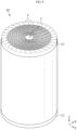
- a battery 1 may be a cylindrical battery.
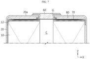
- the cylindrical battery 1 includes an electrode assembly 10, a housing 20, a first current collector 30, a cap 40, a spacer 50 and a terminal 60.
- the cylindrical battery 1 may further include an insulation gasket G and/or a second current collector 70 and/or an insulator 80.
- the present disclosure is not limited by the shape of the battery, and may be applied to batteries of other shapes, for example, prismatic batteries.
- the electrode assembly 10 includes a first uncoated region 11 and a second uncoated region 12.
- the electrode assembly 10 includes a first electrode having a first polarity, a second electrode having a second polarity and a separator interposed between the first electrode and the second electrode.
- the first electrode corresponds to a negative or positive electrode
- the second electrode corresponds to an electrode having the opposite polarity to the first electrode.
- the electrode assembly 10 may have, for example, a jelly-roll shape. That is, the electrode assembly 10 may be manufactured by winding a stack formed by stacking the first electrode, the separator and the second electrode at least once in that order.
- the jelly-roll type electrode assembly 10 may have a winding center hole C at the center, the winding center hole C extending along the heightwise direction (a direction parallel to the Z axis). Meanwhile, an additional separator may be provided on the outer peripheral surface of the electrode assembly 10 for insulation from the housing 20.
- the first electrode includes a first conductive substrate and a first electrode active material layer formed on one or two surfaces of the first conductive substrate.
- a first electrode uncoated region in which a first electrode active material is not coated, exists at one end of the first conductive substrate in the widthwise direction (the direction parallel to the Z axis).
- the first electrode uncoated region extends from one end to the other end along the lengthwise direction of the first electrode when viewing the first electrode in unfolded state.
- the first electrode uncoated region 11 may act as a first electrode tab.
- the first uncoated region 11 is provided on one surface of the electrode assembly 10. More specifically, the first uncoated region 11 is provided below the electrode assembly 10 received within the housing 20 in the heightwise direction (the direction parallel to the Z axis).
- the second electrode includes a second conductive substrate and a second electrode active material layer formed on one or two surfaces of the second conductive substrate.
- An uncoated region in which a second electrode active material is not coated, exists at the other end of the second conductive substrate in the widthwise direction (the direction parallel to the Z axis).
- the second electrode uncoated region extends from one end to the other end along the lengthwise direction of the second electrode when viewing the second electrode in unfolded state.
- the second electrode uncoated region 12 may act as a second electrode tab.
- the second uncoated region 12 is provided on the other surface of the electrode assembly 10. More specifically, the second uncoated region 12 is provided on the electrode assembly 10 received within the housing 20 in the heightwise direction (the direction parallel to the Z axis).
- first uncoated region 11 and the second uncoated region 12 extend and protrude in the opposite directions along the heightwise direction of the electrode assembly 10 (the direction parallel to the Z axis), i.e., the heightwise direction of the cylindrical battery 1, and are exposed to the outside of the separator.
- the first uncoated region 11 and/or the second uncoated region 12 may include a plurality of segments F split along the winding direction of the electrode assembly 10.
- the plurality of segments may be bent along the radial direction of the electrode assembly 10.
- the plurality of bent segments may overlap in multiple layers.
- the first current collector 30 and/or the second current collector 70 as described below may be coupled to an area in which the plurality of segments F overlaps in multiple layers.
- the electrode assembly 10 may have a target welding area in which the number of overlapping layers of the segments F of the first uncoated region 11 is uniformly maintained along the radial direction of the electrode assembly 10.
- the number of overlapping layers is maintained approximately at the maximum, and thus it may be advantageous to perform, in the above-described area, welding between the first current collector 30 and the first uncoated region 11 and/or welding between the second current collector 70 and the second uncoated region 12 as described below.
- welding when the output of the laser is increased to improve the welding quality, this prevents the electrode assembly 10 from being damaged by the laser beam passing through the first uncoated region 11 and/or the second uncoated region 12. Additionally, this effectively prevents impurities such as weld spatter from entering the electrode assembly 10.
- the positive electrode active material coated on the positive electrode current collector and the negative electrode active material coated on the negative electrode current collector may include any active material known in the corresponding technical field pertaining to the present disclosure without limitations.
- the positive electrode active material may include an alkali metal compound represented by general formula A[A x M y ]O 2+z (A includes at least one of Li, Na or K; M includes at least one selected from Ni, Co, Mn, Ca, Mg, Al, Ti, Si, Fe, Mo, V, Zr, Zn, Cu, Al, Mo, Sc, Zr, Ru, and Cr; x ⁇ 0, 1 ⁇ x+y ⁇ 2, -0.1 ⁇ z ⁇ 2; the stoichiometric coefficient of the components included in x, y, z and M is selected to keep the compound electrically neutral).
- A includes at least one of Li, Na or K
- M includes at least one selected from Ni, Co, Mn, Ca, Mg, Al, Ti, Si, Fe, Mo, V, Zr, Zn, Cu, Al, Mo, Sc, Zr, Ru, and Cr
- the positive electrode active material may include an alkali metal compound xLiM 1 O 2 -(l-x)Li 2 M 2 O 3 (M 1 includes at least one element having the mean oxidation state of 3; M 2 includes at least one element having the mean oxidation state of 4; 0 ⁇ x ⁇ 1) disclosed by US6,677,082 and US6,680,143 .
- the positive electrode active material may include lithium metal phosphate represented by general formula Li a M 1 x Fe 1-x M 2 y P 1-y M 3 z O 4-z
- M 1 includes at least one selected from Ti, Si, Mn, Co, Fe, V, Cr, Mo, Ni, Nd, Al, Mg and Al
- M 2 includes at least one selected from Ti, Si, Mn, Co, Fe, V, Cr, Mo, Ni, Nd, Al, Mg, Al, As, Sb, Si, Ge, V and S
- M 3 includes a halogen group element selectively including F; 0 ⁇ a ⁇ 2, 0 ⁇ x ⁇ 1, 0 ⁇ y ⁇ 1, 0 ⁇ z ⁇ 1; the stoichiometric coefficient of the components included in a, x, y, z, M 1 , M 2 and M 3 is selected to keep the compound electrically neutral), or Li 3 M 2 (PO 4 ) 3 [M includes at least one selected from Ti, Si, Mn
- the positive electrode active material may include primary particles and/or secondary particles formed by agglomeration of the primary particles.
- the negative electrode active material may include a carbon material, lithium metal or a lithium metal compound, silicon or a silicon compound, tin or a tin compound.
- Metal oxide having the potential of less than 2V such as TiO 2 and SnO 2 may be used for the negative electrode active material.
- the carbon material may include a low crystalline carbon and a high crystalline carbon.
- the separator may include, for example, a porous polymer film made of a polyolefin-based polymer such as an ethylene homopolymer, a propylene homopolymer, an ethylene/butene copolymer, an ethylene/hexene copolymer and an ethylene/methacrylate copolymer, used singly or a stack of them.
- the separator may include a commonly used porous nonwoven fabric, for example, a nonwoven fabric made of high melting point glass fibers and polyethylene terephthalate fibers.
- a coating layer of inorganic particles may be included on at least one surface of the separator. Additionally, the separator itself may be a coating layer of inorganic particles. The particles that form the coating layer may have a bond structure with a binder to create interstitial volume between adjacent particles.
- the inorganic particles may include inorganic particles having the dielectric constant of 5 or more.
- Non-limiting examples of the inorganic particles may include at least one material selected from the group consisting of Pb(Zr,Ti)O 3 (PZT), Pb 1-x La x Zr 1-y Ti y O 3 (PLZT), PB(Mg 3 Nb 2/3 )O 3 -PbTiO 3 (PMN-PT), BaTiO 3 , hafnia (HfO 2 ), SrTiO 3 , TiO 2 , Al 2 O 3 , ZrO 2 , SnO 2 , CeO 2 , MgO, CaO, ZnO and Y 2 O 3 .
- An electrolyte may be a salt having a structure such as A + B - .
- a + includes an alkali metal cation such as Li + , Na + , K + or a combination thereof.
- B - includes at least one anion selected from the group consisting of F - , Cl - , Br - , I - , NO 3 - , N(CN) 2 - , BF 4 - , ClO 4 - , AlO 4 - , AlCl 4 - , PF 6 - , SbF 6 - , AsF 6 - , BF 2 C 2 O 4 - , BC 4 O 8 - , (CF 3 ) 2 PF 4 - , (CF 3 ) 3 PF 3 - , (CF 3 ) 4 PF 2 - , (CF 3 ) 5 PF - , (CF 3 ) 6 P - , CF 3 SO 3 - , C 4 F 9 SO 3
- the electrolyte may be used by dissolving in an organic solvent.
- the organic solvent may include at least one of propylene carbonate (PC), ethylene carbonate (EC), diethyl carbonate (DEC), dimethyl carbonate (DMC), dipropyl carbonate (DPC), dimethyl sulfoxide, acetonitrile, dimethoxyethane, diethoxyethane, tetrahydrofuran, N-methyl-2-pyrrolidone (NMP), ethyl methyl carbonate (EMC) or ⁇ -butyrolactone.
- PC propylene carbonate
- EC ethylene carbonate
- DEC diethyl carbonate
- DMC dimethyl carbonate
- DPC dipropyl carbonate
- dimethyl sulfoxide acetonitrile, dimethoxyethane, diethoxyethane, tetrahydrofuran
- NMP N-methyl-2-pyrrolidone
- EMC ethyl
- the housing 20 receives the electrode assembly 10 through an opening formed on bottom.
- the housing 20 is an approximately cylindrical receiving structure having the opening on bottom and a closed portion on top.
- the housing 20 may be made of a material having conductive properties such as a metal.
- the material of the housing 20 may be, for example, aluminum.
- the side (outer peripheral surface) and the upper surfaces of the housing 20 may be integrally formed.
- the upper surface (the surface parallel to the X-Y plane) of the housing 20 may have an approximately flat shape.
- the housing 20 receives the electrolyte together with the electrode assembly 10 through the opening formed on bottom.
- the housing 20 is electrically connected to the electrode assembly 10.
- the housing 20 is connected to the first uncoated region 11 of the electrode assembly 10. Accordingly, the housing 20 has electrically the same polarity as the first uncoated region 11.
- the housing 20 may include a beading portion 21 and a crimping portion 22 formed at the lower end.
- the beading portion 21 is disposed below the electrode assembly 10 received in the housing 20.
- the beading portion 21 is formed by press-fitting the outer periphery of the housing 20.
- the beading portion 21 may partially reduce the inner diameter of the housing 20 to prevent the electrode assembly 10 having a size approximately corresponding to the width of the housing 20 from exiting the opening formed on bottom of the housing 20.
- the beading portion 21 may act as a support in which the cap 40 is seated.
- the crimping portion 22 is formed below the beading portion 21.
- the crimping portion 22 extends and bend such that an end of the housing defining the opening of the housing 10 surrounds the periphery of the cap 30 with the periphery of the spacer 50 interposed between.
- the first current collector 30 may be coupled to the first uncoated region 11 of the electrode assembly 10 and disposed within the housing 20.
- the first current collector 30 covers at least part of one surface on the bottom of the electrode assembly 10.
- the assembly including the electrode assembly 10 and the first current collector 30 may be inserted into the housing 20 through the opening formed on bottom of the housing 20.
- the first current collector 30 is electrically connected to the housing 20. That is, the first current collector 30 may act as a medium for electrical connection between the electrode assembly 10 and the housing 20.
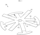
- the first current collector 30 may include, for example, a support portion 31, an uncoated region coupling portion 32 and a housing contact portion 33.
- the support portion 31 is disposed at the approximately center on one surface formed on the bottom of the electrode assembly 10.
- the support portion 31 may have a first current collector hole H1.
- the first current collector hole H1 may be formed at a location corresponding to the winding center hole C of the electrode assembly 10.
- the first current collector hole H1 may act as a passage for insertion of a welding rod for coupling between the terminal 60 and the second current collector 70 or a passage for laser radiation as described below.
- the first current collector hole H1 may act as a passage for smooth permeation of the electrolyte solution into the electrode assembly 10 when injecting the electrolyte solution.
- the uncoated region coupling portion 32 extends from the support portion 31 and is coupled to the first uncoated region 11.
- each of the plurality of uncoated region coupling portions 32 may extend radially from the support portion 31.
- the housing contact portion 33 may extend from the support portion 31 as shown in FIG. 3 , or as opposed to FIG. 3 , the housing contact portion 33 may extend from the end of the uncoated region coupling portion 32.
- the end of the housing contact portion 33 may contact the housing 20 between a sealing portion 52 of the spacer 50 as described below and the housing 20, thereby establishing an electrical connection between the housing 20 and the first current collector 30.
- the end of the housing contact portion 33 may contact one surface of the beading portion 21 facing the cap 40.
- each of the plurality of housing contact portions 33 may extend from the end of each of the plurality of uncoated region coupling portions 32.
- the cap 40 covers the opening formed in the housing 20.
- the cap 40 may be made of a metal material to ensure stiffness.
- the cap 40 forms the lower surface of the cylindrical battery 1.
- the cap 40 may be non-polar even when the cap 40 is made of a metal material having conductivity properties. Non-polar may represent that the cap 40 is electrically insulated from the housing 20 and the terminal 60. Accordingly, the cap 40 does not act as a positive electrode terminal or a negative electrode terminal. Accordingly, the cap 40 does not need to be electrically connected to the electrode assembly 10 and the housing 20, and the cap 40 is not necessarily made of a conductive metal.
- the cap 40 When the housing 20 of the present disclosure includes the beading portion 21, the cap 40 may be seated on the beading portion 21 formed in the housing 20. Additionally, when the housing 20 of the present disclosure includes the crimping portion 22, the cap 40 is fixed by the crimping portion 22. The periphery of the spacer 50 is interposed between the cap 40 and the crimping portion 22 of the housing 20 to ensure sealability of the housing 20.
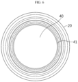
- the cap 40 may further include a venting portion 41 to prevent the internal pressure from rising above a preset value due to gas generated in the housing 20.
- the venting portion 41 corresponds to an area having a smaller thickness than the other areas in the cap 40.
- the venting portion 41 is structurally vulnerable than any other area. Accordingly, when the internal pressure of the housing 20 rises above the predetermined level due to an abnormality in the cylindrical battery 1, the venting portion 41 may rupture to force gas generated in the housing 20 out.
- the venting portion 41 may be formed by notching one or two surfaces of the cap 40 to partially reduce the thickness of the housing 20.
- the lower end of the cap 40 is preferably disposed higher than the lower end of the housing 20.
- the cap 40 does not contact the ground or the bottom of the housing. Accordingly, it is possible to prevent a phenomenon in which the pressure required for the rupture of the venting portion 41 is different from the design value due to the weight of the cylindrical battery 1, thereby allowing for smooth rupture of the venting portion 41.
- venting portion 41 has a closed loop shape as shown in FIGS. 4 and 6 , it is more advantageous in terms of the easiness of rupture as the distance from the center of the cap 40 to the venting portion 41 is longer.
- a force applied to the venting portion 41 is larger, which makes rupture easier.
- FIG. 6 shows the venting portion 41 continuously formed in an approximately circular shape
- the venting portion 41 may be discontinuously formed on the cap 40 in an approximately circular shape, and may be formed in the shape of an approximately straight line or other shapes.
- the spacer 50 is configured to prevent the movement of the electrode assembly 10, and enhance the sealability of the housing 20. That is, the spacer 50 is interposed between the cap 40 and the electrode assembly 10 to fix the electrode assembly 10 and seal up the housing 20.
- the spacer 50 may include a central portion which supports the bottom of the first current collector 30 and a peripheral portion which contacts the housing 20.
- the upper surface of the central portion may be disposed higher than the upper surface of the peripheral portion.
- the upper surface of the central portion may contact the lower surface of the first current collector 30, and the lower surface of the central portion may contact the inner surface of the cap 40.
- the central portion may include a spacer hole H2 formed at a location corresponding to the winding center hole C of the electrode assembly 10.
- the peripheral portion may extend to the inner surface of the housing 20.
- the spacer 50 may further include a flange which extends downward from the outer edges of the peripheral portion. In this case, the flange may be bent together with the housing 20 when crimping the housing 20 so that the flange may be disposed around the edges of the cap 40.
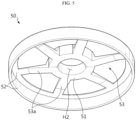
- the spacer 50 may include, for example, a movement prevention portion 51, the sealing portion 52 and a connection portion 53.
- the movement prevention portion 51 is interposed between the first current collector 30 and the cap 40.
- the movement prevention portion 51 may have a height corresponding to the distance between the first current collector 30 and the cap 40.
- the movement prevention portion 51 may effectively prevent the electrode assembly 10 from moving in the housing 20 due to the gap formed between the first current collector 30 and the cap 40. Accordingly, the movement prevention portion 51 may prevent damage from occurring in the coupling part between the electrode assembly 10 and the first current collector 30 and/or the coupling part between the first current collector 30 and the housing 20.
- the movement prevention portion 51 may be disposed at approximately the center of one surface on the bottom of the electrode assembly 10.
- the movement prevention portion 51 may have the spacer hole H2 formed at the location corresponding to the winding center hole C of the electrode assembly 10.
- the spacer hole H2 may act as an insertion passage of a welding rod or a passage for laser radiation.
- the spacer hole H2 may act as a passage for smooth permeation of the electrolyte solution into the electrode assembly 10 when injecting the electrolyte solution.
- the movement prevention portion 51 may cover the support portion 31 to prevent the support portion 31 of the first current collector 30 from being exposed to the outside of the movement prevention portion 51. That is, the outer diameter of the top of the movement prevention portion 51 may be approximately equal to or larger than the outer diameter of the support portion 31. In this case, the movement prevention portion 51 may effectively press down the first current collector 30.
- the movement prevention portion 51 may be configured to cover at least part of a welding portion formed by welding the uncoated region coupling portion 32 of the first current collector 30 to the first uncoated region 11. That is, the radius of the top of the movement prevention portion 51 may be larger than the distance from the welding portion closest to the core of the electrode assembly 10 to the core of the electrode assembly 10. In this case, the movement prevention portion 51 may effectively prevent damage of the welded part of the first current collector 30 and the first uncoated region 11, for example, in the crimping or sizing process.
- the movement prevention portion 51 may be disposed at the inner position toward the core than the venting portion 41 not to cover the venting portion 41 formed in the cap 40. That is, the radius measured on top of the movement prevention portion 51 may be smaller than the distance from the center of the cap 40 to the venting portion 41. This is to prevent a phenomenon in which the venting portion 41 is covered by the spacer 50 and thus the rupture pressure of the venting portion 41 is different from the design value.
- the sealing portion 52 is interposed between the housing 20 and the cap 40.
- the sealing portion 52 may extend along the inner periphery of the housing 20.
- the sealing portion 52 may be bent along the bent shape of the crimping portion 22 so that the sealing portion 52 may be disposed around the peripheral area of the cap 40.
- the sealing portion 52 may be bent along the crimping portion 22 to fill in between the housing contact portion 33 and the cap 40 while surrounding the edges of the cap 40.
- the sealing portion 52 may act as a gasket to improve the fixation of the cap 40 and the sealability of the housing 20.
- the sealing portion 52 may have a smaller thickness between the housing contact portion 33 and the cap 40 than the thickness between the beading portion 21 and the cap 40. It is because the sealing portion 52 may be compressed in the area in which the housing contact portion 33 is interposed between the housing 40 and the beading portion 21 more than in the other areas. Accordingly, the compression ratio of the sealing portion 52 between the housing contact portion 33 and the cap 40 is larger than the compression ratio of the sealing portion 52 between the beading portion 21 and the cap 40.
- the sealing portion 52 may be configured such that the compression ratio between the housing contact portion 33 and the cap 40 is approximately equal to the compression ratio between the beading portion 21 and the cap 40. In this case, it is possible to prevent the partial reduction in sealability due to difference of compressibility ratio for each area.
- connection portion 53 connects the movement prevention portion 51 to the sealing portion 52.
- the connection portion 53 may include a plurality of extension legs 53a extending from the movement prevention portion 51 in a radial or crisscross shape or a combined shape thereof.
- the plurality of extension legs 53a may be configured to avoid contacting the remaining parts except parts of the housing contact portion 33 of the first current collector 30 inserted between the crimping portion 22 and/or the cap 40.
- the connection portion 53 may not overlap the housing contact portion 33 along the heightwise direction of the cylindrical battery 1 (the direction parallel to the Z axis).
- the extension legs 53a and the housing contact portions 33 may be arranged in a staggered pattern to prevent them from overlapping along the vertical direction.
- the spacer 50 even though the shape of the spacer 50 is changed by a sizing process of compressing the cylindrical battery 1 along the heightwise direction (the direction parallel to the Z axis) or other reasons, it is possible to minimize the interference between the connection portion 53 of the spacer 50 and the housing contact portion 33 of the first current collector 30.
- the extension legs 53a are configured to avoid contacting the cap 40, even though the shape of the housing 20 is changed by the sizing process or external impacts, it is possible to reduce the likelihood that the shape change of the extension legs 53a occurs.
- each element of the spacer 50 may be integrally formed.
- the movement prevention portion 51, the sealing portion 52 and the connection portion 53 may be integrated into the spacer 50 by injection molding. That is, the cylindrical battery 1 of the present disclosure can obtain the enhanced sealing effect for the opening of the housing 20 and the movement prevention effect of the electrode assembly 10 through design modification to the gasket component used to seal the opening of the housing 20. Accordingly, according to the present disclosure, it is possible to prevent the increase in manufacturing process complexity and manufacturing cost caused by the application of additional components.
- the terminal 60 is electrically connected to the second uncoated region 12 of the electrode assembly 10.
- the terminal 60 may pass through approximately the center of the closed portion formed on top of the housing 20. Part of the terminal 60 may be exposed through the top of the housing 20, and the others may be disposed within the housing 20.
- the terminal 60 may be fixed onto the inner surface of the closed portion of the housing 20 by riveting.
- the closed portion formed on top of the housing 20 may act as a first electrode terminal 20a having the first polarity.
- the terminal 60 is electrically connected to the second uncoated region 12 of the electrode assembly 10
- the terminal 60 exposed to the outside of the housing 20 may act as a second electrode terminal.
- the cylindrical battery 1 of the present disclosure has a structure in which the pair of electrode terminals 60, 20a are disposed in the same direction. Accordingly, in the electrical connection of the plurality of cylindrical batteries 1, an electrical connection component such as a bus bar may be placed on only one side of the cylindrical battery 1. This may bring about a simple battery pack structure and improved energy density. Additionally, the cylindrical battery 1 has a structure in which one surface of the housing 20 having an approximately flat shape may be used as the first electrode terminal 20a, thereby ensuring a sufficient joining area for joining the electrical connection component such as a bus bar to the first electrode terminal 20a. Accordingly, the cylindrical battery 1 may have sufficient joining strength between the electrical connection component and the first electrode terminal 20a and reduce the resistance at the joined part to a desirable level.
- the terminal 60 when the terminal 60 acts as the second electrode terminal, the terminal 60 is electrically insulated from the housing 20 having the first polarity.
- the electrical insulation between the housing 20 and the terminal 60 may be achieved by various methods. For example, insulation may be achieved by interposing an insulation gasket G between the terminal 60 and the housing 20. Alternatively, insulation may be achieved by forming an insulating coating layer in a part of the terminal 60. Alternatively, the terminal 60 and the housing 20 may be spaced apart from each other to prevent them from contacting each other, and the terminal 60 may be structurally firmly fixed. Alternatively, two or more of the above-described methods may be applied together.
- the insulation gasket G when the insulation gasket G is applied for electrical insulation and riveting is applied to fix the terminal 60, the insulation gasket G may deform together with the terminal 60 during riveting such that the insulation gasket G is bent toward the inner surface of the closed portion on top of the housing 20.
- the insulation gasket G is made of a resin material, the insulation gasket G may be coupled to the housing 20 and the terminal 60 by heat fusion. In this case, it is possible to enhance sealability at the coupling interface between the insulation gasket G and the terminal 60 and the coupling interface between the insulation gasket G and the housing 20.
- the second current collector 70 is coupled to the upper part of the electrode assembly 10.
- the second current collector 70 is made of a metal material having conductive properties and coupled to the second uncoated region 12.
- the coupling between the second uncoated region 12 and the second current collector 70 may be accomplished by laser welding.
- the insulator 80 is interposed between the closed part formed on top of the housing 20 and the top of the electrode assembly 10 or between the closed part and the second current collector 70.
- the insulator 80 may be made of, for example, a resin material having insulating properties. The insulator 80 prevents the contact between the electrode assembly 10 and the housing 20 and/or the contact between the electrode assembly 10 and the second current collector 70.
- the insulator 80 may be interposed between the top of the outer peripheral surface of the electrode assembly 10 and the inner surface of the housing 20. In this case, it is possible to prevent a short from occurring due to the contact between the second uncoated region 12 of the electrode assembly 10 and the inner surface of the sidewall of the housing 20.
- the insulator 80 may have a height corresponding to the distance between the closed part formed on top of the housing 20 and the electrode assembly 10 or the distance between the closed part and the second current collector 70. In this case, it is possible to prevent the electrode assembly 10 from moving in the housing 20, thereby significantly reducing the likelihood that the coupling part for electrical connection between components may be damaged. When the insulator 80 is applied together with the spacer 50, the movement prevention effect of the electrode assembly 10 may be maximized.
- the insulator 80 may have an opening formed at a location corresponding to the winding center hole C of the electrode assembly 10. Through the opening, the terminal 60 may directly contact the second current collector 70.
- the cylindrical battery 1 of the present disclosure has the minimized resistance through the increased weld area through the bent surface, the diverse current path using the first current collector 30 and the minimized current path length.
- the AC resistance of the cylindrical battery 1 measured through a resistance meter between the positive electrode and the negative electrode and between the terminal 60 and its surrounding flat surface 20a may be approximately 0.5 miliohms to 4 miliohms, and preferably approximately 1 miliohm to 4 miliohm, suitable for fast charging.
- the cylindrical battery may have a ratio of form factor (a value obtained by dividing the diameter of the cylindrical battery by its height, i.e., defined as a ratio of diameter ⁇ to height H) larger than approximately 0.4.
- the form factor refers to a value indicating the diameter and height of the cylindrical battery.
- the diameter of the cylindrical battery may be approximately 40 mm to 50 mm, and the height may be approximately 60 mm to 130 mm.
- the cylindrical battery according to an embodiment of the present disclosure may be, for example 46110 battery, 4875 battery, 48110 battery, 4880 battery, 4680 battery.
- the former two numbers indicate the diameter of the battery and the remaining numbers indicate the height of the battery.
- the uncoated region is susceptible to tear due to high stresses applied in the radial direction when bending the uncoated region. Additionally, to ensure sufficient weld strength and reduce the resistance when welding the current collector to the bent surface area of the uncoated region, it is necessary to sufficiently increase the number of stacks of the uncoated region on the bent surface area. This requirement may be met according to the electrode and the electrode assembly according to the embodiments (variations) of the present disclosure.
- the battery according to an embodiment of the present disclosure may be a cylindrical battery having an approximately cylindrical shape with the diameter of approximately 46 mm, the height of approximately 110 mm and the ratio of form factor of approximately 0.418.
- the battery according to another embodiment may be a cylindrical battery having an approximately cylindrical shape with the diameter of approximately 48 mm, the height of approximately 75 mm and the ratio of form factor of approximately 0.640.
- the battery according to another embodiment may be a cylindrical battery having an approximately cylindrical shape with the diameter of approximately 48 mm, the height of approximately 110 mm and the ratio of form factor of approximately 0.418.
- the battery according to another embodiment may be a cylindrical battery having an approximately cylindrical shape with the diameter of approximately 48 mm, the height of approximately 80 mm, and the ratio of form factor of approximately 0.600.
- the battery according to another embodiment may be a cylindrical battery having an approximately cylindrical shape with the diameter of approximately 46 mm, the height of approximately 80 mm, and the ratio of form factor of approximately 0.575.
- batteries having the ratio of form factor of approximately 0.4 or less have been used. That is, for example, 1865 battery and 2170 battery have been used.
- 1865 battery the diameter is approximately 18 mm
- the height is approximately 65 mm
- the ratio of form factor is approximately 0.277.
- 2170 battery the diameter is approximately 21 mm
- the height is approximately 70 mm
- the ratio of form factor is approximately 0.300.
- a method for manufacturing the battery 1 of the present disclosure as described above includes inserting the electrode assembly 10 into the housing; placing the current collector (the first current collector) 30 on the bottom surface of the electrode assembly 10; placing the spacer 50 in contact with the current collector 30; sealing the housing 20 with the edges of the spacer 50; and connecting the cap 40 to the housing 20.
- the manufacturing method may further include connecting the cap 40 to the edges of the spacer 50 such that the spacer 50 extends from the cap 40 to the current collector 30.
- the edges of the spacer 50 sealing the housing 20 may extend along the circumferential direction.
- the plurality of cylindrical batteries 1 may be connected in series and in parallel using a busbar 150 on the cylindrical batteries 1.
- the number of cylindrical batteries 1 may be smaller or larger, considering the capacity of a battery pack.
- the terminal 60 may have the positive polarity, and the outer surface 20a of the closed portion of the housing 20 may have the negative polarity, and vice versa.
- the plurality of cylindrical batteries 1 may be arranged in a plurality of columns and rows.
- the column is a vertical direction with respect to fFig. 10, and the row is a horizontal direction with respect to the Fig. 10 .
- the cylindrical batteries 1 may be arranged in a closest packing structure.
- the closest packing structure is formed by connecting the centers of the terminals 60 exposed to the outside of the housing 20 to each other into a shape of a right triangle.
- the busbar 150 may be positioned on the plurality of cylindrical batteries 1, more preferably between adjacent columns. Alternatively, the busbar 150 may be positioned between adjacent rows.
- the busbar 150 connects in parallel the batteries 1 arranged in the same column, and connects in series the cylindrical batteries 1 arranged in two adjacent columns.
- the busbar 150 may include a body portion 151, a plurality of first busbar terminals 152 and a plurality of second busbar terminals 153 for series and parallel connection.
- the body portion 151 may extend between the terminals 60 of the adjacent cylindrical batteries 1, and preferably between the columns of the cylindrical batteries 1. Alternatively, the body portion 151 may extend along the columns of the cylindrical batteries 1 and may be regularly bent in a zigzag pattern.
- the plurality of first busbar terminals 152 may extend and protrude from one side of the body portion 151 to the terminal 60 of each cylindrical battery 1, and be electrically coupled to the terminal 40.
- the electrical coupling between the first busbar terminal 152 and the terminal 60 may be accomplished by laser welding, ultrasonic welding, etc.
- the plurality of second busbar terminals 153 may be electrically coupled to the outer surface 20a of each cylindrical battery 1 from the other side of the body portion 151.
- the electrical coupling between the second busbar terminals 153 and the outer surfaces 20a may be accomplished by laser welding, ultrasonic welding, etc.
- the body portion 151, the plurality of first busbar terminals 152 and the plurality of second busbar terminals 153 may be made from a single conductive metal plate.
- the metal plate may include, for example, an aluminum plate or a copper plate, but the present disclosure is not limited thereto.
- the body portion 151, the plurality of first busbar terminals 152 and the plurality of second busbar terminals 153 may be separately manufactured by the unit of a piece and then coupled to each other, for example, through welding.
- the cylindrical battery 1 according to the present disclosure is configured such that the terminal 60 having the positive polarity and the outer surface 20a of the closed portion of the housing 20 having the negative polarity are positioned in the same direction, it is possible to easily establish an electrical connection of the cylindrical batteries 1 using the busbar 150.
- the terminal 60 and the outer surface 20a of the closed portion of the housing 20 have large areas, it is possible to sufficiently reduce the resistance of a battery pack including the cylindrical battery 1 due to a sufficient coupling area of the busbar 150.
- a battery pack 3 includes a battery assembly including a plurality of cylindrical batteries 1 electrically connected according to an embodiment of the present disclosure as described above and a pack housing 2 in which the battery assembly is received.
- the electrical connection structure of the plurality of batteries 1 through the busbar has been described with reference to FIG. 10 for illustrative purposes, and a cooling unit and a power terminal are omitted for convenience of illustration in the drawings.
- a vehicle 5 may be, for example, an electric vehicle, a hybrid electric vehicle and a plugin hybrid electric vehicle, and includes the battery pack 3 according to an embodiment of the present disclosure.
- the vehicle 5 includes a four-wheeler and a two-wheeler. The vehicle 5 works by the power supplied from the battery pack 3 according to an embodiment of the present disclosure.
Landscapes
- Chemical & Material Sciences (AREA)
- Chemical Kinetics & Catalysis (AREA)
- Electrochemistry (AREA)
- General Chemical & Material Sciences (AREA)
- Engineering & Computer Science (AREA)
- Manufacturing & Machinery (AREA)
- Aviation & Aerospace Engineering (AREA)
- Connection Of Batteries Or Terminals (AREA)
- Battery Mounting, Suspending (AREA)
- Sealing Battery Cases Or Jackets (AREA)
- Cell Separators (AREA)
- Filling, Topping-Up Batteries (AREA)
- Secondary Cells (AREA)
Abstract
Description
- The present disclosure relates to a battery, and a battery pack and a vehicle comprising the same. More particularly, the present disclosure relates to a battery having a structure capable of minimizing the movement of an electrode assembly inside thereof, and a battery pack and a vehicle comprising the same.
- The present application claims the benefit of
Korean Patent Application No. 10-2021-0022894 filed on February 19, 2021 Korean Patent Application No. 10-2021-0022893 filed on February 19, 2021 Korean Patent Application No. 10-2021-0022881 filed on February 19, 2021 Korean Patent Application No. 10-2021-0030291 filed on March 08, 2021 Korean Patent Application No. 10-2021-0131215 filed on October 01, 2021 Korean Patent Application No. 10-2021-0131207 filed on October 01, 2021 Korean Patent Application No. 10-2021-0131208 filed on October 01, 2021 Korean Patent Application No. 10-2021-0147363 filed on October 29, 2021 - In a battery, a jelly roll having a positive electrode tab and a negative electrode tab extending upward and downward along the longitudinal direction of a housing respectively may be applied to maximize the current collection efficiency. In the battery to which the jelly roll having this structure is applied, a current collector may be used as an intermediary to connect the positive electrode tab and the negative electrode tab to a terminal and the housing respectively.
- In this case, for example, the positive electrode current collector may be coupled to the positive electrode tab while covering one surface of the jelly roll, and the negative electrode current collector may be coupled to the negative electrode tab while covering the other surface of the jelly roll. Additionally, the positive electrode current collector may be electrically connected to the terminal, and the negative electrode current collector may be electrically connected to the housing.
- The battery having the above-described structure may have a relatively large empty space, in particular, between the negative electrode current collector and a cap. Additionally, an empty space may be formd between the bottom of the housing disposed opposite the cap and the positive electrode current collector.
- These empty spaces may cause the jelly roll to move within the housing, in particular, along the vertical direction, i.e., the heightwise direction of the battery. When the jelly roll moves in the vertical direction, damage may occur to the coupling part between the current collector and the electrode tab, and moreover, damage may occur to the coupling part between the current collector and the housing and the coupling part between the current collector and the terminal.
- Accordingly, it is necessary to minimize the movement space of the jelly roll. Additionally, when an additional component is applied to reduce the movement space of the jelly roll, the procedural complexity may increase and the manufacturing cost may rise, and accordingly there is a need to solve the problem by making use of the existing component.
- The present disclosure is designed to solve the above-described problem, and therefore the present disclosure is directed to prevent damage from occurring in an electrical coupling part due to the movement of a jelly roll in a housing.
- The present disclosure is further directed to prevent the movement of a jelly roll by making use of an existing component in the manufacture of a battery, thereby preventing the increase in manufacturing process complexity and manufacturing cost caused by the application of an additional component.
- However, the technical problem of the present disclosure is not limited to the above-described problem, and other problems not mentioned herein will be clearly understood by those skilled in the art from the following description.
- To solve the above-described problem, a battery according to an embodiment of the present disclosure includes an electrode assembly including a first electrode and a second electrode and a separator interposed between the first electrode and the second electrode, the first electrode, the second electrode and the separator being wound around a winding axis to define a core and an outer peripheral surface, wherein the first electrode and the second electrode include a first uncoated region and a second uncoated region along a winding direction, respectively, and an active material layer coating is absent in the first uncoated region and the second uncoated region; a housing receiving the electrode assembly through an opening formed at a bottom; a first current collector coupled to the first uncoated region and disposed within the housing; a cap covering the opening; a spacer interposed between the cap and the electrode assembly to fix the electrode assembly and seal the housing; and a terminal electrically connected to the second uncoated region.
- The spacer may include a movement prevention portion between the first current collector and the cap; a sealing portion between the housing and the cap; and a connection portion connecting the movement prevention portion to the sealing portion.
- A height of the movement prevention portion may correspond to a distance between the first current collector and the cap.
- The movement prevention portion may be at a center on one surface of the electrode assembly.
- The movement prevention portion may include a spacer hole at a location corresponding to a winding center hole of the electrode assembly.
- The sealing portion may extend along an inner periphery of the housing.
- The housing may include a beading portion formed by press-fitting an outer periphery; and a crimping portion of which an end of the housing defining the opening is extended and bent to surround edges of the cap below the beading portion.
- The sealing portion may be bent along the crimping portion and surround the edges of the cap.
- The connection portion may include a plurality of extension legs extending from the movement prevention portion in a radial or crisscross shape or a combined shape thereof.
- The plurality of extension legs may be configured to avoid contacting the first current collector.
- The plurality of extension legs may be configured to maintain a distance from the cap.
- The first current collector may include a support portion at a center on a surface of the electrode assembly; a uncoated region coupling portion extending from the support portion and coupled to the first uncoated region; and a housing contact portion extending from the support portion or an end of the uncoated region coupling portion and interposed between the housing and the sealing portion.
- The support portion may include a first current collector hole at a location corresponding to a winding center hole of the electrode assembly.
- The housing may include a beading portion of which part of sidewall is press-fit inward; and a crimping portion of which an end of the housing defining the opening is extended and bent around edges of the cap below the beading portion. In this instance, the housing contact portion may contact a surface of the beading portion facing the cap.
- The sealing portion may be bent along the crimping portion, and fill in between the housing contact portion and the cap while surrounding the edges of the cap.
- The sealing portion may have a smaller thickness between the housing contact portion and the cap which than a thickness between the beading portion and the cap.
- A compression ratio of the sealing portion between the housing contact portion and the cap may be larger than a compression ratio of the sealing portion between the beading portion and the cap.
- A compression ratio of the sealing portion between the housing contact portion and the cap may be equal to a compression ratio of the sealing portion between the beading portion and the cap.
- The movement prevention portion may cover the support portion to prevent the support portion from being exposed to outside of the movement prevention portion.
- The cap may include a venting portion having a smaller thickness than its surrounding area, and the movement prevention portion may be disposed at an inner position than the venting portion to prevent the movement prevention portion from covering the venting portion.
- The connection portion may not overlap the housing contact portion along a heightwise direction of the battery.
- The battery may further include a second current collector coupled to the first uncoated region; and an insulator interposed between a closed portion on top of the housing and the second current collector.
- A height of the insulator may correspond to a distance between the second current collector and the closed portion.
- To solve the above-described problem, a battery pack according to an embodiment of the present disclosure includes a plurality of batteries according to an embodiment of the present disclosure as described above.
- The plurality of batteries may be arranged in a predetermined number of columns, and in this instance, the terminal and the outer surface of the closed portion of the housing of each battery may be positioned facing upward.
- The battery pack may include a plurality of busbars to connect the plurality of batteries in series and in parallel, and the plurality of busbars may be arranged on the plurality of batteries. In this instance, each busbar may include a body portion extending between the terminals of the adjacent batteries; a plurality of first busbar terminals extending in a direction of the body portion and electrically coupled to the terminals of the batteries disposed in the said direction; and a plurality of second busbar terminals extending in an opposite direction of the body portion and electrically coupled to the outer surfaces of the closed portions of the housings of the batteries disposed in the opposite direction.
- To solve the above-described problem, a vehicle according to an embodiment of the present disclosure includes the battery pack according to an embodiment of the present disclosure.
- Meanwhile, according to another aspect, to solve the above-described problem, a battery according to an embodiment of the present disclosure may include an electrode assembly including a first uncoated region and a second uncoated region; a housing receiving the electrode assembly through an opening formed on a bottom; a first current collector coupled to the first uncoated region in the housing; and a spacer including a central portion which support a bottom of the first current collector and a peripheral portion which contacts the housing.
- The battery may further include a terminal electrically connected to the second uncoated region.
- An upper surface of the central portion may be disposed at a higher position than an upper surface of the peripheral portion.
- The central portion may include a spacer hole at a location corresponding to the winding center hole of the electrode assembly.
- The peripheral portion may extend to an inner surface of the housing.
- The spacer may further include a flange extending downward from outer edges of the peripheral portion.
- The battery may further include a cap covering an opening at a lower end of the housing, and an upper surface of the central portion may contact a lower surface of the first current collector, and a lower surface of the central portion may contact an inner surface of the cap.
- Meanwhile, to solve the above-described problem, a method for manufacturing a battery according to an embodiment of the present disclosure includes inserting an electrode assembly into a housing; placing a current collector on a bottom surface of the electrode assembly; placing a spacer in contact with the current collector; sealing the housing with edges of the spacer; and connecting a cap to the housing.
- The method for manufacturing a battery may further include connecting the cap to the edges of the spacer such that the spacer extends from the cap to the current collector.
- The edges of the spacer sealing the housing may extend along a circumferential direction.
- According to an aspect of the present disclosure, it is possible to minimize the movement of the jelly roll in the housing, thereby preventing damage from occurring in the electrical coupling part.
- According to another aspect of the present disclosure, it is possible to prevent the increase in manufacturing process complexity and manufacturing cost by making use of an existing component rather than additionally applying a component for preventing the movement of the jelly roll.
- The accompanying drawings illustrate a preferred embodiment of the present disclosure, and together with the detailed description of the present disclosure described below, serve to provide a further understanding of the technical aspects of the present disclosure, and thus the present disclosure should not be construed as being limited to the drawings.
-
FIG. 1 is a perspective view showing a cylindrical battery according to an embodiment of the present disclosure. -
FIG. 2 is a cross-sectional view showing the internal structure of a cylindrical battery according to an embodiment of the present disclosure. -
FIG. 3 is a perspective view showing an exemplary shape of a first current collector applied to the present disclosure. -
FIG. 4 is a partial cross-sectional view showing an area in which an integrated spacer of the present disclosure is applied. -
FIG. 5 is a bottom perspective view of the integrated spacer of the present disclosure. -
FIG. 6 is a bottom view of a cylindrical battery of the present disclosure. -
FIG. 7 is a partial cross-sectional view showing an area in which an insulator of the present disclosure is applied. -
FIG. 8 is a diagram showing an electrode assembly having segments of the present disclosure. -
FIG. 9 is a top view showing a plurality of cylindrical batteries according to an embodiment of the present disclosure connected in series and in parallel using a busbar. -
FIG. 10 is a schematic view showing a battery pack according to an embodiment of the present disclosure. -
FIG. 11 is a conceptual diagram showing a vehicle according to an embodiment of the present disclosure. - Hereinafter, the preferred embodiments of the present disclosure will be described in detail with reference to the accompanying drawings. Prior to the description, it should be understood that the terms or words used in the specification and the appended claims should not be construed as being limited to general and dictionary meanings, but rather interpreted based on the meanings and concepts corresponding to the technical aspects of the present disclosure on the basis of the principle that the inventor is allowed to define the terms appropriately for the best explanation. Therefore, the embodiments described herein and illustrations shown in the drawings are just some most preferred embodiments of the present disclosure, but not intended to fully describe the technical aspects of the present disclosure, so it should be understood that a variety of other equivalents and modifications could have been made thereto at the time that the application was filed.
- In addition, to help the understanding of the present disclosure, the accompanying drawings may illustrate some elements in exaggerated dimensions, not in actual scale. Furthermore, the same element in different embodiments may be given the same reference numeral.
- The term equal refers to 'substantially equal'. Accordingly, substantially equal may include the deviation regarded as a low level in the corresponding technical field, for example, the deviation of 5% or less. In addition, a uniform parameter in a predetermined area may refer to uniform from the average point of view.
- The terms "first", "second" and the like, are used to describe a variety of elements, these elements are not limited by the terms. These terms are used to distinguish one element from another, and unless the context clearly indicates otherwise, a first element may be a second element.
- As used herein, the singular forms are intended to include the plural forms as well, unless the context clearly indicates otherwise.
- It will be understood that when an element is referred to being "on (or below)" or "above (or under)" another element, it can be positioned in contact with an upper surface (or a lower surface) of the other element, but another element may be positioned between the element and the other element on (or below) the element.
- It will be further understood that when an element is referred to as being "connected", "coupled" or "joined" to another element, the elements can be directly connected or joined to each other, but intervening elements may be present between them or each element may be "connected", "coupled" or "joined" to each other through another element.
- Unless the context clearly indicates otherwise, "A and/or B" refers to A, B or A and B, and "C to D" refers to C or more and D or less.
- Referring to
FIGS. 1 and2 , abattery 1 according to an embodiment of the present disclosure may be a cylindrical battery. Thecylindrical battery 1 includes anelectrode assembly 10, ahousing 20, a firstcurrent collector 30, acap 40, aspacer 50 and a terminal 60. In addition to the above-described elements, thecylindrical battery 1 may further include an insulation gasket G and/or a secondcurrent collector 70 and/or aninsulator 80. The present disclosure is not limited by the shape of the battery, and may be applied to batteries of other shapes, for example, prismatic batteries. - Referring to
FIGS. 2 ,4 ,7 and8 , theelectrode assembly 10 includes a firstuncoated region 11 and a seconduncoated region 12. Theelectrode assembly 10 includes a first electrode having a first polarity, a second electrode having a second polarity and a separator interposed between the first electrode and the second electrode. The first electrode corresponds to a negative or positive electrode, and the second electrode corresponds to an electrode having the opposite polarity to the first electrode. - The
electrode assembly 10 may have, for example, a jelly-roll shape. That is, theelectrode assembly 10 may be manufactured by winding a stack formed by stacking the first electrode, the separator and the second electrode at least once in that order. The jelly-rolltype electrode assembly 10 may have a winding center hole C at the center, the winding center hole C extending along the heightwise direction (a direction parallel to the Z axis). Meanwhile, an additional separator may be provided on the outer peripheral surface of theelectrode assembly 10 for insulation from thehousing 20. - The first electrode includes a first conductive substrate and a first electrode active material layer formed on one or two surfaces of the first conductive substrate. A first electrode uncoated region, in which a first electrode active material is not coated, exists at one end of the first conductive substrate in the widthwise direction (the direction parallel to the Z axis). The first electrode uncoated region extends from one end to the other end along the lengthwise direction of the first electrode when viewing the first electrode in unfolded state. The first electrode
uncoated region 11 may act as a first electrode tab. The firstuncoated region 11 is provided on one surface of theelectrode assembly 10. More specifically, the firstuncoated region 11 is provided below theelectrode assembly 10 received within thehousing 20 in the heightwise direction (the direction parallel to the Z axis). - The second electrode includes a second conductive substrate and a second electrode active material layer formed on one or two surfaces of the second conductive substrate. An uncoated region, in which a second electrode active material is not coated, exists at the other end of the second conductive substrate in the widthwise direction (the direction parallel to the Z axis). The second electrode uncoated region extends from one end to the other end along the lengthwise direction of the second electrode when viewing the second electrode in unfolded state. The second electrode
uncoated region 12 may act as a second electrode tab. The seconduncoated region 12 is provided on the other surface of theelectrode assembly 10. More specifically, the seconduncoated region 12 is provided on theelectrode assembly 10 received within thehousing 20 in the heightwise direction (the direction parallel to the Z axis). - That is, the first
uncoated region 11 and the seconduncoated region 12 extend and protrude in the opposite directions along the heightwise direction of the electrode assembly 10 (the direction parallel to the Z axis), i.e., the heightwise direction of thecylindrical battery 1, and are exposed to the outside of the separator. - Meanwhile, referring to
FIG. 8 , at least part of the firstuncoated region 11 and/or the seconduncoated region 12 may include a plurality of segments F split along the winding direction of theelectrode assembly 10. In this case, the plurality of segments may be bent along the radial direction of theelectrode assembly 10. The plurality of bent segments may overlap in multiple layers. In this case, the firstcurrent collector 30 and/or the secondcurrent collector 70 as described below may be coupled to an area in which the plurality of segments F overlaps in multiple layers. Meanwhile, theelectrode assembly 10 may have a target welding area in which the number of overlapping layers of the segments F of the firstuncoated region 11 is uniformly maintained along the radial direction of theelectrode assembly 10. In this area, the number of overlapping layers is maintained approximately at the maximum, and thus it may be advantageous to perform, in the above-described area, welding between the firstcurrent collector 30 and the firstuncoated region 11 and/or welding between the secondcurrent collector 70 and the seconduncoated region 12 as described below. For example, in case that laser welding is applied, when the output of the laser is increased to improve the welding quality, this prevents theelectrode assembly 10 from being damaged by the laser beam passing through the firstuncoated region 11 and/or the seconduncoated region 12. Additionally, this effectively prevents impurities such as weld spatter from entering theelectrode assembly 10. - In the present disclosure, the positive electrode active material coated on the positive electrode current collector and the negative electrode active material coated on the negative electrode current collector may include any active material known in the corresponding technical field pertaining to the present disclosure without limitations.
- In an example, the positive electrode active material may include an alkali metal compound represented by general formula A[AxMy]O2+z (A includes at least one of Li, Na or K; M includes at least one selected from Ni, Co, Mn, Ca, Mg, Al, Ti, Si, Fe, Mo, V, Zr, Zn, Cu, Al, Mo, Sc, Zr, Ru, and Cr; x ≥ 0, 1 ≤ x+y ≤2, -0.1 ≤ z ≤ 2; the stoichiometric coefficient of the components included in x, y, z and M is selected to keep the compound electrically neutral).
- In another example, the positive electrode active material may include an alkali metal compound xLiM1O2-(l-x)Li2M2O3 (M1 includes at least one element having the mean oxidation state of 3; M2 includes at least one element having the mean oxidation state of 4; 0≤x≤1) disclosed by
US6,677,082 andUS6,680,143 . - In still another example, the positive electrode active material may include lithium metal phosphate represented by general formula LiaM1 xFe1-xM2 yP1-yM3 zO4-z (M1 includes at least one selected from Ti, Si, Mn, Co, Fe, V, Cr, Mo, Ni, Nd, Al, Mg and Al; M2 includes at least one selected from Ti, Si, Mn, Co, Fe, V, Cr, Mo, Ni, Nd, Al, Mg, Al, As, Sb, Si, Ge, V and S; M3 includes a halogen group element selectively including F; 0 < a ≤2, 0 ≤ x ≤ 1, 0 ≤ y < 1, 0 ≤ z < 1; the stoichiometric coefficient of the components included in a, x, y, z, M1, M2 and M3 is selected to keep the compound electrically neutral), or Li3M2(PO4)3 [M includes at least one selected from Ti, Si, Mn, Fe, Co, V, Cr, Mo, Ni, Al, Mg and Al].
- Preferably, the positive electrode active material may include primary particles and/or secondary particles formed by agglomeration of the primary particles.
- In an example, the negative electrode active material may include a carbon material, lithium metal or a lithium metal compound, silicon or a silicon compound, tin or a tin compound. Metal oxide having the potential of less than 2V such as TiO2 and SnO2 may be used for the negative electrode active material. The carbon material may include a low crystalline carbon and a high crystalline carbon.
- The separator may include, for example, a porous polymer film made of a polyolefin-based polymer such as an ethylene homopolymer, a propylene homopolymer, an ethylene/butene copolymer, an ethylene/hexene copolymer and an ethylene/methacrylate copolymer, used singly or a stack of them. In another example, the separator may include a commonly used porous nonwoven fabric, for example, a nonwoven fabric made of high melting point glass fibers and polyethylene terephthalate fibers.
- A coating layer of inorganic particles may be included on at least one surface of the separator. Additionally, the separator itself may be a coating layer of inorganic particles. The particles that form the coating layer may have a bond structure with a binder to create interstitial volume between adjacent particles.
- The inorganic particles may include inorganic particles having the dielectric constant of 5 or more. Non-limiting examples of the inorganic particles may include at least one material selected from the group consisting of Pb(Zr,Ti)O3 (PZT), Pb1-xLaxZr1-yTiyO3 (PLZT), PB(Mg3Nb2/3)O3-PbTiO3 (PMN-PT), BaTiO3, hafnia (HfO2), SrTiO3, TiO2, Al2O3, ZrO2, SnO2, CeO2, MgO, CaO, ZnO and Y2O3.
- An electrolyte may be a salt having a structure such as A+B-. Here, A+ includes an alkali metal cation such as Li+, Na+, K+ or a combination thereof. B- includes at least one anion selected from the group consisting of F-, Cl-, Br-, I-, NO3 -, N(CN)2 -, BF4 -, ClO4 -, AlO4 -, AlCl4 -, PF6 -, SbF6 -, AsF6 -, BF2C2O4 -, BC4O8 -, (CF3)2PF4 -, (CF3)3PF3 -, (CF3)4PF2 -, (CF3)5PF-, (CF3)6P-, CF3SO3 -, C4F9SO3 -, CF3CF2SO3 -, (CF3SO2)2N-, (FSO2)2N-,CF3CF2(CF3)2CO-, (CF3SO2)2CH-, (SF5)3C-, (CF3SO2)3C-, CF3(CF2)7SO3 -, CF3CO2 -, CH3CO2 -, SCN- and (CF3CF2SO2)2N-.
- The electrolyte may be used by dissolving in an organic solvent. The organic solvent may include at least one of propylene carbonate (PC), ethylene carbonate (EC), diethyl carbonate (DEC), dimethyl carbonate (DMC), dipropyl carbonate (DPC), dimethyl sulfoxide, acetonitrile, dimethoxyethane, diethoxyethane, tetrahydrofuran, N-methyl-2-pyrrolidone (NMP), ethyl methyl carbonate (EMC) or γ-butyrolactone.
- Referring to
FIGS. 1 ,2 ,4 and7 , thehousing 20 receives theelectrode assembly 10 through an opening formed on bottom. Thehousing 20 is an approximately cylindrical receiving structure having the opening on bottom and a closed portion on top. Thehousing 20 may be made of a material having conductive properties such as a metal. The material of thehousing 20 may be, for example, aluminum. The side (outer peripheral surface) and the upper surfaces of thehousing 20 may be integrally formed. The upper surface (the surface parallel to the X-Y plane) of thehousing 20 may have an approximately flat shape. Thehousing 20 receives the electrolyte together with theelectrode assembly 10 through the opening formed on bottom. - The
housing 20 is electrically connected to theelectrode assembly 10. Thehousing 20 is connected to the firstuncoated region 11 of theelectrode assembly 10. Accordingly, thehousing 20 has electrically the same polarity as the firstuncoated region 11. - Referring to
FIGS. 2 and4 , thehousing 20 may include abeading portion 21 and a crimpingportion 22 formed at the lower end. Thebeading portion 21 is disposed below theelectrode assembly 10 received in thehousing 20. Thebeading portion 21 is formed by press-fitting the outer periphery of thehousing 20. Thebeading portion 21 may partially reduce the inner diameter of thehousing 20 to prevent theelectrode assembly 10 having a size approximately corresponding to the width of thehousing 20 from exiting the opening formed on bottom of thehousing 20. Thebeading portion 21 may act as a support in which thecap 40 is seated. - The crimping
portion 22 is formed below thebeading portion 21. The crimpingportion 22 extends and bend such that an end of the housing defining the opening of thehousing 10 surrounds the periphery of thecap 30 with the periphery of thespacer 50 interposed between. - Referring to
FIGS. 2 to 4 , the firstcurrent collector 30 may be coupled to the firstuncoated region 11 of theelectrode assembly 10 and disposed within thehousing 20. The firstcurrent collector 30 covers at least part of one surface on the bottom of theelectrode assembly 10. The assembly including theelectrode assembly 10 and the firstcurrent collector 30 may be inserted into thehousing 20 through the opening formed on bottom of thehousing 20. The firstcurrent collector 30 is electrically connected to thehousing 20. That is, the firstcurrent collector 30 may act as a medium for electrical connection between theelectrode assembly 10 and thehousing 20. - Referring to
FIG. 3 , the firstcurrent collector 30 may include, for example, asupport portion 31, an uncoatedregion coupling portion 32 and ahousing contact portion 33. Thesupport portion 31 is disposed at the approximately center on one surface formed on the bottom of theelectrode assembly 10. Thesupport portion 31 may have a first current collector hole H1. In this case, the first current collector hole H1 may be formed at a location corresponding to the winding center hole C of theelectrode assembly 10. The first current collector hole H1 may act as a passage for insertion of a welding rod for coupling between the terminal 60 and the secondcurrent collector 70 or a passage for laser radiation as described below. Besides, the first current collector hole H1 may act as a passage for smooth permeation of the electrolyte solution into theelectrode assembly 10 when injecting the electrolyte solution. - The uncoated
region coupling portion 32 extends from thesupport portion 31 and is coupled to the firstuncoated region 11. For example, there may be a plurality of uncoatedregion coupling portions 32. In this case, each of the plurality of uncoatedregion coupling portions 32 may extend radially from thesupport portion 31. Thehousing contact portion 33 may extend from thesupport portion 31 as shown inFIG. 3 , or as opposed toFIG. 3 , thehousing contact portion 33 may extend from the end of the uncoatedregion coupling portion 32. The end of thehousing contact portion 33 may contact thehousing 20 between a sealingportion 52 of thespacer 50 as described below and thehousing 20, thereby establishing an electrical connection between thehousing 20 and the firstcurrent collector 30. For example, the end of thehousing contact portion 33 may contact one surface of thebeading portion 21 facing thecap 40. - For example, there may be a plurality of
housing contact portions 33. In this case, the plurality ofhousing contact portions 33 may extend radially from thesupport portion 31 as shown inFIG. 3 , and at least onehousing contact portion 33 may be disposed between the adjacent uncoatedregion coupling portions 32. Alternatively, as opposed toFIG. 3 , each of the plurality ofhousing contact portions 33 may extend from the end of each of the plurality of uncoatedregion coupling portions 32. - Referring to
FIGS. 2 ,4 and6 , thecap 40 covers the opening formed in thehousing 20. For example, thecap 40 may be made of a metal material to ensure stiffness. Thecap 40 forms the lower surface of thecylindrical battery 1. In thecylindrical battery 1 of the present disclosure, thecap 40 may be non-polar even when thecap 40 is made of a metal material having conductivity properties. Non-polar may represent that thecap 40 is electrically insulated from thehousing 20 and the terminal 60. Accordingly, thecap 40 does not act as a positive electrode terminal or a negative electrode terminal. Accordingly, thecap 40 does not need to be electrically connected to theelectrode assembly 10 and thehousing 20, and thecap 40 is not necessarily made of a conductive metal. - When the
housing 20 of the present disclosure includes thebeading portion 21, thecap 40 may be seated on thebeading portion 21 formed in thehousing 20. Additionally, when thehousing 20 of the present disclosure includes the crimpingportion 22, thecap 40 is fixed by the crimpingportion 22. The periphery of thespacer 50 is interposed between thecap 40 and the crimpingportion 22 of thehousing 20 to ensure sealability of thehousing 20. - Referring to
FIGS. 4 and6 , thecap 40 may further include a ventingportion 41 to prevent the internal pressure from rising above a preset value due to gas generated in thehousing 20. The ventingportion 41 corresponds to an area having a smaller thickness than the other areas in thecap 40. The ventingportion 41 is structurally vulnerable than any other area. Accordingly, when the internal pressure of thehousing 20 rises above the predetermined level due to an abnormality in thecylindrical battery 1, the ventingportion 41 may rupture to force gas generated in thehousing 20 out. For example, the ventingportion 41 may be formed by notching one or two surfaces of thecap 40 to partially reduce the thickness of thehousing 20. - As shown in
FIG. 7 , the lower end of thecap 40 is preferably disposed higher than the lower end of thehousing 20. In this case, even when the lower end of thehousing 20 contacts the ground or the bottom of the housing for forming a module or a pack, thecap 40 does not contact the ground or the bottom of the housing. Accordingly, it is possible to prevent a phenomenon in which the pressure required for the rupture of the ventingportion 41 is different from the design value due to the weight of thecylindrical battery 1, thereby allowing for smooth rupture of the ventingportion 41. - Meanwhile, when the venting
portion 41 has a closed loop shape as shown inFIGS. 4 and6 , it is more advantageous in terms of the easiness of rupture as the distance from the center of thecap 40 to the ventingportion 41 is longer. When the same venting pressure is applied, as the distance from the center of thecap 40 to the ventingportion 41 is longer, a force applied to the ventingportion 41 is larger, which makes rupture easier. Additionally, it is more advantageous in terms of smooth venting gas discharge as the distance from the center of thecap 40 to the ventingportion 41 is longer. From this perspective, it is advantageous that the ventingportion 41 is formed along the periphery of an approximately flat area extended downward (on the basis ofFIG. 4 ) from the peripheral area of thecap 40. - Although
FIG. 6 shows the ventingportion 41 continuously formed in an approximately circular shape, the present disclosure is not limited thereto. The ventingportion 41 may be discontinuously formed on thecap 40 in an approximately circular shape, and may be formed in the shape of an approximately straight line or other shapes. - Referring to
FIGS. 2 ,4 and5 , thespacer 50 is configured to prevent the movement of theelectrode assembly 10, and enhance the sealability of thehousing 20. That is, thespacer 50 is interposed between thecap 40 and theelectrode assembly 10 to fix theelectrode assembly 10 and seal up thehousing 20. Thespacer 50 may include a central portion which supports the bottom of the firstcurrent collector 30 and a peripheral portion which contacts thehousing 20. In this case, the upper surface of the central portion may be disposed higher than the upper surface of the peripheral portion. The upper surface of the central portion may contact the lower surface of the firstcurrent collector 30, and the lower surface of the central portion may contact the inner surface of thecap 40. The central portion may include a spacer hole H2 formed at a location corresponding to the winding center hole C of theelectrode assembly 10. The peripheral portion may extend to the inner surface of thehousing 20. Thespacer 50 may further include a flange which extends downward from the outer edges of the peripheral portion. In this case, the flange may be bent together with thehousing 20 when crimping thehousing 20 so that the flange may be disposed around the edges of thecap 40. - In another aspect, the
spacer 50 may include, for example, amovement prevention portion 51, the sealingportion 52 and aconnection portion 53. Themovement prevention portion 51 is interposed between the firstcurrent collector 30 and thecap 40. Themovement prevention portion 51 may have a height corresponding to the distance between the firstcurrent collector 30 and thecap 40. In this case, themovement prevention portion 51 may effectively prevent theelectrode assembly 10 from moving in thehousing 20 due to the gap formed between the firstcurrent collector 30 and thecap 40. Accordingly, themovement prevention portion 51 may prevent damage from occurring in the coupling part between theelectrode assembly 10 and the firstcurrent collector 30 and/or the coupling part between the firstcurrent collector 30 and thehousing 20. - The
movement prevention portion 51 may be disposed at approximately the center of one surface on the bottom of theelectrode assembly 10. Themovement prevention portion 51 may have the spacer hole H2 formed at the location corresponding to the winding center hole C of theelectrode assembly 10. In the same way as the above-described first current collector hole H1, the spacer hole H2 may act as an insertion passage of a welding rod or a passage for laser radiation. In the same way as the above-described first current collector hole H1, the spacer hole H2 may act as a passage for smooth permeation of the electrolyte solution into theelectrode assembly 10 when injecting the electrolyte solution. - Meanwhile, the
movement prevention portion 51 may cover thesupport portion 31 to prevent thesupport portion 31 of the firstcurrent collector 30 from being exposed to the outside of themovement prevention portion 51. That is, the outer diameter of the top of themovement prevention portion 51 may be approximately equal to or larger than the outer diameter of thesupport portion 31. In this case, themovement prevention portion 51 may effectively press down the firstcurrent collector 30. - In another aspect, the
movement prevention portion 51 may be configured to cover at least part of a welding portion formed by welding the uncoatedregion coupling portion 32 of the firstcurrent collector 30 to the firstuncoated region 11. That is, the radius of the top of themovement prevention portion 51 may be larger than the distance from the welding portion closest to the core of theelectrode assembly 10 to the core of theelectrode assembly 10. In this case, themovement prevention portion 51 may effectively prevent damage of the welded part of the firstcurrent collector 30 and the firstuncoated region 11, for example, in the crimping or sizing process. - In still another aspect, the
movement prevention portion 51 may be disposed at the inner position toward the core than the ventingportion 41 not to cover the ventingportion 41 formed in thecap 40. That is, the radius measured on top of themovement prevention portion 51 may be smaller than the distance from the center of thecap 40 to the ventingportion 41. This is to prevent a phenomenon in which the ventingportion 41 is covered by thespacer 50 and thus the rupture pressure of the ventingportion 41 is different from the design value. - The sealing
portion 52 is interposed between thehousing 20 and thecap 40. The sealingportion 52 may extend along the inner periphery of thehousing 20. When thehousing 20 includes the crimpingportion 22, the sealingportion 52 may be bent along the bent shape of the crimpingportion 22 so that the sealingportion 52 may be disposed around the peripheral area of thecap 40. In another aspect, the sealingportion 52 may be bent along the crimpingportion 22 to fill in between thehousing contact portion 33 and thecap 40 while surrounding the edges of thecap 40. As described above, the sealingportion 52 may act as a gasket to improve the fixation of thecap 40 and the sealability of thehousing 20. - Meanwhile, the sealing
portion 52 may have a smaller thickness between thehousing contact portion 33 and thecap 40 than the thickness between the beadingportion 21 and thecap 40. It is because the sealingportion 52 may be compressed in the area in which thehousing contact portion 33 is interposed between thehousing 40 and thebeading portion 21 more than in the other areas. Accordingly, the compression ratio of the sealingportion 52 between thehousing contact portion 33 and thecap 40 is larger than the compression ratio of the sealingportion 52 between the beadingportion 21 and thecap 40. By contrast, the sealingportion 52 may be configured such that the compression ratio between thehousing contact portion 33 and thecap 40 is approximately equal to the compression ratio between the beadingportion 21 and thecap 40. In this case, it is possible to prevent the partial reduction in sealability due to difference of compressibility ratio for each area. - The
connection portion 53 connects themovement prevention portion 51 to the sealingportion 52. For example, theconnection portion 53 may include a plurality ofextension legs 53a extending from themovement prevention portion 51 in a radial or crisscross shape or a combined shape thereof. When theconnection portion 53 is configured as described above, it is possible to inject the electrolyte solution well through a space between theadjacent extension legs 53a, and release gas inside when venting occurs due to the rise in the internal pressure. - As shown in
FIG. 4 , the plurality ofextension legs 53a may be configured to avoid contacting the remaining parts except parts of thehousing contact portion 33 of the firstcurrent collector 30 inserted between the crimpingportion 22 and/or thecap 40. For example, theconnection portion 53 may not overlap thehousing contact portion 33 along the heightwise direction of the cylindrical battery 1 (the direction parallel to the Z axis). In particular, when theextension legs 53a extend radially from themovement prevention portion 51 and the plurality ofhousing contact portions 33 extends radially from thesupport portion 31, theextension legs 53a and thehousing contact portions 33 may be arranged in a staggered pattern to prevent them from overlapping along the vertical direction. In this case, even though the shape of the components is changed by the compressive force applied to thehousing 20 in the vertical direction, it is possible to significantly reduce the likelihood that interference between theextension legs 53a and thehousing contact portions 33 occurs, thereby significantly reducing the likelihood that the coupling parts between components are damaged. - In this case, even though the shape of the
spacer 50 is changed by a sizing process of compressing thecylindrical battery 1 along the heightwise direction (the direction parallel to the Z axis) or other reasons, it is possible to minimize the interference between theconnection portion 53 of thespacer 50 and thehousing contact portion 33 of the firstcurrent collector 30. In particular, when theextension legs 53a are configured to avoid contacting thecap 40, even though the shape of thehousing 20 is changed by the sizing process or external impacts, it is possible to reduce the likelihood that the shape change of theextension legs 53a occurs. - Meanwhile, each element of the
spacer 50 may be integrally formed. For example, themovement prevention portion 51, the sealingportion 52 and theconnection portion 53 may be integrated into thespacer 50 by injection molding. That is, thecylindrical battery 1 of the present disclosure can obtain the enhanced sealing effect for the opening of thehousing 20 and the movement prevention effect of theelectrode assembly 10 through design modification to the gasket component used to seal the opening of thehousing 20. Accordingly, according to the present disclosure, it is possible to prevent the increase in manufacturing process complexity and manufacturing cost caused by the application of additional components. - Referring to
FIGS. 1 ,2 and7 , the terminal 60 is electrically connected to the seconduncoated region 12 of theelectrode assembly 10. For example, the terminal 60 may pass through approximately the center of the closed portion formed on top of thehousing 20. Part of the terminal 60 may be exposed through the top of thehousing 20, and the others may be disposed within thehousing 20. For example, the terminal 60 may be fixed onto the inner surface of the closed portion of thehousing 20 by riveting. - As described above, in the present disclosure, as the
housing 20 is electrically connected to the firstuncoated region 11 of theelectrode assembly 10, the closed portion formed on top of thehousing 20 may act as afirst electrode terminal 20a having the first polarity. By contrast, as the terminal 60 is electrically connected to the seconduncoated region 12 of theelectrode assembly 10, the terminal 60 exposed to the outside of thehousing 20 may act as a second electrode terminal. - That is, the
cylindrical battery 1 of the present disclosure has a structure in which the pair ofelectrode terminals cylindrical batteries 1, an electrical connection component such as a bus bar may be placed on only one side of thecylindrical battery 1. This may bring about a simple battery pack structure and improved energy density. Additionally, thecylindrical battery 1 has a structure in which one surface of thehousing 20 having an approximately flat shape may be used as thefirst electrode terminal 20a, thereby ensuring a sufficient joining area for joining the electrical connection component such as a bus bar to thefirst electrode terminal 20a. Accordingly, thecylindrical battery 1 may have sufficient joining strength between the electrical connection component and thefirst electrode terminal 20a and reduce the resistance at the joined part to a desirable level. - As described above, when the terminal 60 acts as the second electrode terminal, the terminal 60 is electrically insulated from the
housing 20 having the first polarity. The electrical insulation between thehousing 20 and the terminal 60 may be achieved by various methods. For example, insulation may be achieved by interposing an insulation gasket G between the terminal 60 and thehousing 20. Alternatively, insulation may be achieved by forming an insulating coating layer in a part of the terminal 60. Alternatively, the terminal 60 and thehousing 20 may be spaced apart from each other to prevent them from contacting each other, and the terminal 60 may be structurally firmly fixed. Alternatively, two or more of the above-described methods may be applied together. - Meanwhile, when the insulation gasket G is applied for electrical insulation and riveting is applied to fix the terminal 60, the insulation gasket G may deform together with the terminal 60 during riveting such that the insulation gasket G is bent toward the inner surface of the closed portion on top of the
housing 20. When the insulation gasket G is made of a resin material, the insulation gasket G may be coupled to thehousing 20 and the terminal 60 by heat fusion. In this case, it is possible to enhance sealability at the coupling interface between the insulation gasket G and the terminal 60 and the coupling interface between the insulation gasket G and thehousing 20. - Referring to
FIGS. 2 and7 , the secondcurrent collector 70 is coupled to the upper part of theelectrode assembly 10. The secondcurrent collector 70 is made of a metal material having conductive properties and coupled to the seconduncoated region 12. For example, the coupling between the seconduncoated region 12 and the secondcurrent collector 70 may be accomplished by laser welding. - Referring to
FIGS. 2 and7 , theinsulator 80 is interposed between the closed part formed on top of thehousing 20 and the top of theelectrode assembly 10 or between the closed part and the secondcurrent collector 70. Theinsulator 80 may be made of, for example, a resin material having insulating properties. Theinsulator 80 prevents the contact between theelectrode assembly 10 and thehousing 20 and/or the contact between theelectrode assembly 10 and the secondcurrent collector 70. - Besides, the
insulator 80 may be interposed between the top of the outer peripheral surface of theelectrode assembly 10 and the inner surface of thehousing 20. In this case, it is possible to prevent a short from occurring due to the contact between the seconduncoated region 12 of theelectrode assembly 10 and the inner surface of the sidewall of thehousing 20. - The
insulator 80 may have a height corresponding to the distance between the closed part formed on top of thehousing 20 and theelectrode assembly 10 or the distance between the closed part and the secondcurrent collector 70. In this case, it is possible to prevent theelectrode assembly 10 from moving in thehousing 20, thereby significantly reducing the likelihood that the coupling part for electrical connection between components may be damaged. When theinsulator 80 is applied together with thespacer 50, the movement prevention effect of theelectrode assembly 10 may be maximized. - The
insulator 80 may have an opening formed at a location corresponding to the winding center hole C of theelectrode assembly 10. Through the opening, the terminal 60 may directly contact the secondcurrent collector 70. - The
cylindrical battery 1 of the present disclosure has the minimized resistance through the increased weld area through the bent surface, the diverse current path using the firstcurrent collector 30 and the minimized current path length. The AC resistance of thecylindrical battery 1 measured through a resistance meter between the positive electrode and the negative electrode and between the terminal 60 and its surroundingflat surface 20a may be approximately 0.5 miliohms to 4 miliohms, and preferably approximately 1 miliohm to 4 miliohm, suitable for fast charging. - Preferably, the cylindrical battery may have a ratio of form factor (a value obtained by dividing the diameter of the cylindrical battery by its height, i.e., defined as a ratio of diameter Φ to height H) larger than approximately 0.4.
- Here, the form factor refers to a value indicating the diameter and height of the cylindrical battery. Preferably, the diameter of the cylindrical battery may be approximately 40 mm to 50 mm, and the height may be approximately 60 mm to 130 mm. The cylindrical battery according to an embodiment of the present disclosure may be, for example 46110 battery, 4875 battery, 48110 battery, 4880 battery, 4680 battery. In the value indicating the form factor, the former two numbers indicate the diameter of the battery and the remaining numbers indicate the height of the battery.
- When the electrode assembly having a tab-less structure is applied to the cylindrical battery having the ratio of form factor of higher than 0.4, the uncoated region is susceptible to tear due to high stresses applied in the radial direction when bending the uncoated region. Additionally, to ensure sufficient weld strength and reduce the resistance when welding the current collector to the bent surface area of the uncoated region, it is necessary to sufficiently increase the number of stacks of the uncoated region on the bent surface area. This requirement may be met according to the electrode and the electrode assembly according to the embodiments (variations) of the present disclosure.
- The battery according to an embodiment of the present disclosure may be a cylindrical battery having an approximately cylindrical shape with the diameter of approximately 46 mm, the height of approximately 110 mm and the ratio of form factor of approximately 0.418.
- The battery according to another embodiment may be a cylindrical battery having an approximately cylindrical shape with the diameter of approximately 48 mm, the height of approximately 75 mm and the ratio of form factor of approximately 0.640.
- The battery according to another embodiment may be a cylindrical battery having an approximately cylindrical shape with the diameter of approximately 48 mm, the height of approximately 110 mm and the ratio of form factor of approximately 0.418.
- The battery according to another embodiment may be a cylindrical battery having an approximately cylindrical shape with the diameter of approximately 48 mm, the height of approximately 80 mm, and the ratio of form factor of approximately 0.600.
- The battery according to another embodiment may be a cylindrical battery having an approximately cylindrical shape with the diameter of approximately 46 mm, the height of approximately 80 mm, and the ratio of form factor of approximately 0.575.
- Conventionally, batteries having the ratio of form factor of approximately 0.4 or less have been used. That is, for example, 1865 battery and 2170 battery have been used. In the case of 1865 battery, the diameter is approximately 18 mm, the height is approximately 65 mm, and the ratio of form factor is approximately 0.277. In the case of 2170 battery, the diameter is approximately 21 mm, the height is approximately 70 mm, and the ratio of form factor is approximately 0.300.
- Meanwhile, a method for manufacturing the
battery 1 of the present disclosure as described above includes inserting theelectrode assembly 10 into the housing; placing the current collector (the first current collector) 30 on the bottom surface of theelectrode assembly 10; placing thespacer 50 in contact with thecurrent collector 30; sealing thehousing 20 with the edges of thespacer 50; and connecting thecap 40 to thehousing 20. - The manufacturing method may further include connecting the
cap 40 to the edges of thespacer 50 such that thespacer 50 extends from thecap 40 to thecurrent collector 30. The edges of thespacer 50 sealing thehousing 20 may extend along the circumferential direction. - Referring to
FIG. 10 , the plurality ofcylindrical batteries 1 may be connected in series and in parallel using abusbar 150 on thecylindrical batteries 1. The number ofcylindrical batteries 1 may be smaller or larger, considering the capacity of a battery pack. - In each
cylindrical battery 1, the terminal 60 may have the positive polarity, and theouter surface 20a of the closed portion of thehousing 20 may have the negative polarity, and vice versa. - Preferably, the plurality of
cylindrical batteries 1 may be arranged in a plurality of columns and rows. The column is a vertical direction with respect to fFig. 10, and the row is a horizontal direction with respect to theFig. 10 . Additionally, in order to maximize the space efficiency, thecylindrical batteries 1 may be arranged in a closest packing structure. The closest packing structure is formed by connecting the centers of theterminals 60 exposed to the outside of thehousing 20 to each other into a shape of a right triangle. Preferably, thebusbar 150 may be positioned on the plurality ofcylindrical batteries 1, more preferably between adjacent columns. Alternatively, thebusbar 150 may be positioned between adjacent rows. - Preferably, the
busbar 150 connects in parallel thebatteries 1 arranged in the same column, and connects in series thecylindrical batteries 1 arranged in two adjacent columns. - Preferably, the
busbar 150 may include abody portion 151, a plurality offirst busbar terminals 152 and a plurality ofsecond busbar terminals 153 for series and parallel connection. - The
body portion 151 may extend between theterminals 60 of the adjacentcylindrical batteries 1, and preferably between the columns of thecylindrical batteries 1. Alternatively, thebody portion 151 may extend along the columns of thecylindrical batteries 1 and may be regularly bent in a zigzag pattern. - The plurality of
first busbar terminals 152 may extend and protrude from one side of thebody portion 151 to theterminal 60 of eachcylindrical battery 1, and be electrically coupled to the terminal 40. The electrical coupling between thefirst busbar terminal 152 and the terminal 60 may be accomplished by laser welding, ultrasonic welding, etc. Additionally, the plurality ofsecond busbar terminals 153 may be electrically coupled to theouter surface 20a of eachcylindrical battery 1 from the other side of thebody portion 151. The electrical coupling between thesecond busbar terminals 153 and theouter surfaces 20a may be accomplished by laser welding, ultrasonic welding, etc. - Preferably, the
body portion 151, the plurality offirst busbar terminals 152 and the plurality ofsecond busbar terminals 153 may be made from a single conductive metal plate. The metal plate may include, for example, an aluminum plate or a copper plate, but the present disclosure is not limited thereto. In a variation, thebody portion 151, the plurality offirst busbar terminals 152 and the plurality ofsecond busbar terminals 153 may be separately manufactured by the unit of a piece and then coupled to each other, for example, through welding. - As the
cylindrical battery 1 according to the present disclosure is configured such that the terminal 60 having the positive polarity and theouter surface 20a of the closed portion of thehousing 20 having the negative polarity are positioned in the same direction, it is possible to easily establish an electrical connection of thecylindrical batteries 1 using thebusbar 150. - Additionally, as the
cylindrical battery 1 the terminal 60 and theouter surface 20a of the closed portion of thehousing 20 have large areas, it is possible to sufficiently reduce the resistance of a battery pack including thecylindrical battery 1 due to a sufficient coupling area of thebusbar 150. - Referring to
FIG. 11 , abattery pack 3 according to an embodiment of the present disclosure includes a battery assembly including a plurality ofcylindrical batteries 1 electrically connected according to an embodiment of the present disclosure as described above and apack housing 2 in which the battery assembly is received. The electrical connection structure of the plurality ofbatteries 1 through the busbar has been described with reference toFIG. 10 for illustrative purposes, and a cooling unit and a power terminal are omitted for convenience of illustration in the drawings. - Referring to FIG. 12, a
vehicle 5 according to an embodiment of the present disclosure may be, for example, an electric vehicle, a hybrid electric vehicle and a plugin hybrid electric vehicle, and includes thebattery pack 3 according to an embodiment of the present disclosure. Thevehicle 5 includes a four-wheeler and a two-wheeler. Thevehicle 5 works by the power supplied from thebattery pack 3 according to an embodiment of the present disclosure. - While the present disclosure has been hereinabove described with regard to a limited number of embodiments and drawings, the present disclosure is not limited thereto and it is obvious to those skilled in the art that a variety of modifications and changes may be made thereto within the technical aspects of the present disclosure and the equivalent scope of the appended claims.
-
- 5: Vehicle
- 3: Battery pack
- 2: Pack housing
- 1: Cylindrical battery
- 10: Electrode assembly
- 11: First uncoated region
- 12: Second uncoated region
- C: Winding center hole
- 20: Housing
- 20a: First electrode terminal
- 21: Beading portion
- 22: Crimping portion
- 30: First current collector
- 31: Support portion
- 32: Uncoated region coupling portion
- 33: Housing contact portion
- H1: First current collector hole
- 40: Cap
- 41: Venting portion
- 50: Spacer
- 51: Movement prevention portion
- H2: Spacer hole
- 52: Sealing portion
- 53: Connection portion
- 53a: Extension leg
- 60: Terminal (Second electrode terminal)
- G: Insulation gasket
- 70: Second current collector
- 80: Insulator
Claims (39)
- A battery, comprising:an electrode assembly including a first electrode and a second electrode and a separator interposed between the first electrode and the second electrode, the first electrode, the second electrode and the separator being wound around a winding axis to define a core and an outer peripheral surface, wherein the first electrode and the second electrode include a first uncoated region and a second uncoated region along a winding direction, respectively, and an active material layer coating is absent in the first uncoated region and the second uncoated region;a housing receiving the electrode assembly through an opening formed at a bottom;a first current collector coupled to the first uncoated region and disposed within the housing;a cap covering the opening;a spacer interposed between the cap and the electrode assembly to fix the electrode assembly and seal the housing; anda terminal electrically connected to the second uncoated region.
- The battery according to claim 1, wherein the spacer includes:a movement prevention portion between the first current collector and the cap;a sealing portion between the housing and the cap; anda connection portion connecting the movement prevention portion to the sealing portion.
- The battery according to claim 2, wherein a height of the movement prevention portion corresponds to a distance between the first current collector and the cap.
- The battery according to claim 2, wherein the movement prevention portion is at a center on one surface of the electrode assembly.
- The battery according to claim 2, wherein the movement prevention portion includes a spacer hole at a location corresponding to a winding center hole of the electrode assembly.
- The battery according to claim 2, wherein the sealing portion extends along an inner periphery of the housing.
- The battery according to claim 6, wherein the housing includes:a beading portion formed by press-fitting an outer periphery; anda crimping portion of which an end of the housing defining the opening is extended and bent to surround edges of the cap below the beading portion.
- The battery according to claim 7, wherein the sealing portion is bent along the crimping portion and surrounds the edges of the cap.
- The battery according to claim 2, wherein the connection portion includes a plurality of extension legs extending from the movement prevention portion in a radial or crisscross shape or a combined shape thereof.
- The battery according to claim 9, wherein the plurality of extension legs is configured to avoid contacting the first current collector.
- The battery according to claim 9, wherein the plurality of extension legs is configured to maintain a distance from the cap.
- The battery according to claim 9, wherein the first current collector includes:a support portion at a center on a surface of the electrode assembly;a uncoated region coupling portion extending from the support portion and coupled to the first uncoated region; anda housing contact portion extending from the support portion or an end of the uncoated region coupling portion and interposed between the housing and the sealing portion.
- The battery according to claim 12, wherein the support portion includes a first current collector hole at a location corresponding to a winding center hole of the electrode assembly.
- The battery according to claim 12, wherein the housing includes:a beading portion of which part of sidewall is press-fit inward; anda crimping portion of which an end of the housing defining the opening is extended and bent around edges of the cap below the beading portion, andwherein the housing contact portion contacts a surface of the beading portion facing the cap.
- The battery according to claim 14, wherein the sealing portion is bent along the crimping portion, and fills in between the housing contact portion and the cap while surrounding the edges of the cap.
- The battery according to claim 15, wherein the sealing portion has a smaller thickness between the housing contact portion and the cap which than a thickness between the beading portion and the cap.
- The battery according to claim 15, wherein a compression ratio of the sealing portion between the housing contact portion and the cap is larger than a compression ratio of the sealing portion between the beading portion and the cap.
- The battery according to claim 15, wherein a compression ratio of the sealing portion between the housing contact portion and the cap is equal to a compression ratio of the sealing portion between the beading portion and the cap.
- The battery according to claim 12, wherein the movement prevention portion covers the support portion to prevent the support portion from being exposed to outside of the movement prevention portion.
- The battery according to claim 2, wherein the cap includes a venting portion having a smaller thickness than its surrounding area, and
the movement prevention portion is disposed at an inner position than the venting portion to prevent the movement prevention portion from covering the venting portion. - The battery according to claim 12, wherein the connection portion does not overlap the housing contact portion along a heightwise direction of the battery.
- The battery according to claim 1, further comprising:a second current collector coupled to the first uncoated region; andan insulator interposed between a closed portion on top of the housing and the second current collector.
- The battery according to claim 22, wherein a height of the insulator corresponds to a distance between the second current collector and the closed portion.
- The battery according to claim 1, wherein a resistance measured between a positive electrode and a negative electrode is 4 miliohm or less.
- The battery according to claim 1, wherein a ratio of form factor calculated by dividing a diameter of the battery by its height is larger than 0.4.
- A battery pack, comprising:
a plurality of batteries according to any one of claims 1 to 25. - The battery pack according to claim 26, wherein the plurality of batteries are arranged in a predetermined number of columns, and
the terminal and the outer surface of the closed portion of the housing of each battery are positioned facing upward. - The battery pack according to claim 26, wherein the battery pack comprises a plurality of busbars to connect the plurality of batteries in series and in parallel,the plurality of busbars are arranged on the plurality of batteries, andeach busbar includes:a body portion extending between the terminals of the adjacent batteries;a plurality of first busbar terminals extending in a direction of the body portion and electrically coupled to the terminals of the batteries disposed in the said direction; anda plurality of second busbar terminals extending in an opposite direction of the body portion and electrically coupled to the outer surfaces of the closed portions of the housings of the batteries disposed in the opposite direction.
- A vehicle comprising the battery pack according to claim 26.
- A battery, comprising:an electrode assembly including a first uncoated region and a second uncoated region;a housing receiving the electrode assembly through an opening formed on a bottom;a first current collector coupled to the first uncoated region in the housing; anda spacer including a central portion which support a bottom of the first current collector and a peripheral portion which contacts the housing.
- The battery according to claim 30, further comprising:
a terminal electrically connected to the second uncoated region. - The battery according to claim 30, wherein an upper surface of the central portion is disposed at a higher position than an upper surface of the peripheral portion.
- The battery according to claim 30, wherein the central portion includes a spacer hole at a location corresponding to the winding center hole of the electrode assembly.
- The battery according to claim 30, wherein the peripheral portion extends to an inner surface of the housing.
- The battery according to claim 34, wherein the spacer further includes a flange extending downward from outer edges of the peripheral portion.
- The battery according to claim 30, further comprising:a cap covering an opening at a lower end of the housing,wherein an upper surface of the central portion contacts a lower surface of the first current collector, and a lower surface of the central portion contacts an inner surface of the cap.
- A method for manufacturing a battery, comprising:inserting an electrode assembly into a housing;placing a current collector on a bottom surface of the electrode assembly;placing a spacer in contact with the current collector;sealing the housing with edges of the spacer; andconnecting a cap to the housing.
- The method for manufacturing a battery according to claim 37, further comprising:
connecting the cap to the edges of the spacer such that the spacer extends from the cap to the current collector. - The method for manufacturing a battery according to claim 37, wherein the edges of the spacer sealing the housing extend along a circumferential direction.
Applications Claiming Priority (9)
| Application Number | Priority Date | Filing Date | Title |
|---|---|---|---|
| KR20210022893 | 2021-02-19 | ||
| KR20210022894 | 2021-02-19 | ||
| KR20210022881 | 2021-02-19 | ||
| KR20210030291 | 2021-03-08 | ||
| KR20210131208 | 2021-10-01 | ||
| KR20210131215 | 2021-10-01 | ||
| KR20210131207 | 2021-10-01 | ||
| KR1020210147363A KR20220118892A (en) | 2021-02-19 | 2021-10-29 | Cylindrical secondary battery cell, and battery pack and vehicle including the same |
| PCT/KR2022/002468 WO2022177377A1 (en) | 2021-02-19 | 2022-02-18 | Battery, and battery pack and vehicle comprising same |
Publications (2)
| Publication Number | Publication Date |
|---|---|
| EP4243196A1 true EP4243196A1 (en) | 2023-09-13 |
| EP4243196A4 EP4243196A4 (en) | 2025-04-30 |
Family
ID=82931033
Family Applications (1)
| Application Number | Title | Priority Date | Filing Date |
|---|---|---|---|
| EP22756575.1A Pending EP4243196A4 (en) | 2021-02-19 | 2022-02-18 | BATTERY, AND BATTERY PACK AND VEHICLE COMPRISING SAME |
Country Status (6)
| Country | Link |
|---|---|
| US (1) | US20240234958A9 (en) |
| EP (1) | EP4243196A4 (en) |
| JP (1) | JP7721647B2 (en) |
| KR (2) | KR102447738B1 (en) |
| CN (2) | CN217740661U (en) |
| WO (1) | WO2022177377A1 (en) |
Cited By (3)
| Publication number | Priority date | Publication date | Assignee | Title |
|---|---|---|---|---|
| EP4593137A1 (en) * | 2024-01-23 | 2025-07-30 | Samsung SDI Co., Ltd. | Cylindrical secondary battery |
| EP4293802A4 (en) * | 2021-10-22 | 2025-08-20 | Lg Energy Solution Ltd | CYLINDRICAL SECONDARY BATTERY AND BATTERY PACK AND VEHICLE THEREOF |
| EP4471973A4 (en) * | 2022-01-25 | 2025-10-29 | Lg Energy Solution Ltd | CYLINDRICAL SECONDARY BATTERY |
Families Citing this family (15)
| Publication number | Priority date | Publication date | Assignee | Title |
|---|---|---|---|---|
| JP7721647B2 (en) * | 2021-02-19 | 2025-08-12 | エルジー エナジー ソリューション リミテッド | Batteries, battery packs containing the same, and automobiles |
| JP7610018B2 (en) * | 2021-07-06 | 2025-01-07 | ジアンス・コンテンポラリー・アンプレックス・テクノロジー・リミテッド | Battery cell, battery, power consumption device, and method and device for manufacturing battery cell |
| CN218827235U (en) * | 2021-10-22 | 2023-04-07 | 株式会社Lg新能源 | Electrode assembly, cylindrical battery, battery pack including the same, and automobile |
| KR102586883B1 (en) * | 2022-09-15 | 2023-10-10 | 삼성에스디아이 주식회사 | Cylindrical secondary battery |
| WO2024055256A1 (en) * | 2022-09-15 | 2024-03-21 | 宁德时代新能源科技股份有限公司 | Battery cell and preparation method therefor, battery, and electrical device |
| KR102559655B1 (en) * | 2022-09-21 | 2023-07-24 | 삼성에스디아이 주식회사 | Rechargeable battery |
| CN119999008A (en) * | 2022-09-30 | 2025-05-13 | 株式会社Lg新能源 | Sealing structure for liquid injection port of battery can, battery cell including the sealing structure, battery and vehicle |
| KR102559656B1 (en) * | 2022-10-06 | 2023-07-24 | 삼성에스디아이 주식회사 | Rechargeable battery |
| KR102586886B1 (en) * | 2022-10-26 | 2023-10-10 | 삼성에스디아이 주식회사 | Cylindrical secondary battery |
| WO2024136617A1 (en) * | 2022-12-23 | 2024-06-27 | 주식회사 엘지에너지솔루션 | Cylindrical secondary battery and method for manufacturing same |
| AU2023205673A1 (en) | 2023-03-01 | 2024-09-19 | Ola Electric Mobility Limited | Current collector plates for batteries |
| WO2024197876A1 (en) * | 2023-03-31 | 2024-10-03 | 宁德新能源科技有限公司 | Battery |
| CN119852604A (en) * | 2023-10-18 | 2025-04-18 | 创科无线普通合伙 | Rolling groove-free battery |
| US20250201986A1 (en) * | 2023-12-14 | 2025-06-19 | Sk On Co., Ltd. | Battery Cell and Manufacturing Method of the Same |
| DE102024115694A1 (en) * | 2024-06-05 | 2025-12-11 | Kautex Textron Gmbh & Co. Kg | Battery housing for accommodating a variety of battery components, battery with a battery housing, motor vehicle with a battery |
Family Cites Families (30)
| Publication number | Priority date | Publication date | Assignee | Title |
|---|---|---|---|---|
| JP3418551B2 (en) | 1998-06-12 | 2003-06-23 | 日本碍子株式会社 | Lithium secondary battery |
| US6677082B2 (en) | 2000-06-22 | 2004-01-13 | The University Of Chicago | Lithium metal oxide electrodes for lithium cells and batteries |
| US6680143B2 (en) | 2000-06-22 | 2004-01-20 | The University Of Chicago | Lithium metal oxide electrodes for lithium cells and batteries |
| DE10144281A1 (en) * | 2001-09-08 | 2003-03-27 | Nbt Gmbh | Galvanic element with winding electrode set |
| JP2004247192A (en) * | 2003-02-14 | 2004-09-02 | Ngk Insulators Ltd | Lithium secondary battery |
| JP4501361B2 (en) * | 2003-06-05 | 2010-07-14 | パナソニック株式会社 | Secondary battery |
| CN2681364Y (en) * | 2004-02-27 | 2005-02-23 | 何策衡 | Rechargeable battery having cathode assembly packaging |
| KR100599598B1 (en) * | 2004-05-04 | 2006-07-13 | 삼성에스디아이 주식회사 | Secondary Battery, Electrode Assembly and Current Collecting Plate Used in the Same |
| JP5051410B2 (en) * | 2005-05-30 | 2012-10-17 | 株式会社Gsユアサ | Sealed battery lead, sealed battery using the lead, and method of manufacturing the battery |
| KR100947962B1 (en) * | 2008-03-17 | 2010-03-15 | 삼성에스디아이 주식회사 | Cylindrical secondary battery |
| JP6232848B2 (en) * | 2012-09-26 | 2017-11-22 | 株式会社Gsユアサ | Electricity storage element |
| KR102007702B1 (en) * | 2013-01-03 | 2019-10-21 | 삼성에스디아이 주식회사 | Rechargeable battery |
| US20140212695A1 (en) * | 2013-01-30 | 2014-07-31 | Tesla Motors, Inc. | Flexible printed circuit as high voltage interconnect in battery modules |
| KR20150070928A (en) | 2013-12-17 | 2015-06-25 | 에스에프씨 주식회사 | An electroluminescent compound and an electroluminescent device comprising the same |
| KR101679413B1 (en) * | 2015-04-03 | 2016-11-25 | (주)오렌지파워 | Hollow-shaped rechargeable battery |
| FR3039709B1 (en) * | 2015-07-28 | 2017-08-18 | Commissariat Energie Atomique | LITHIUM ACCUMULATOR WITH IMPROVED OPERATING SAFETY BY AN INTEGRATED CIRCUIT-SWITCH DEVICE |
| JP2020071898A (en) * | 2017-03-03 | 2020-05-07 | 株式会社Gsユアサ | Power storage element |
| JP7205050B2 (en) * | 2017-09-01 | 2023-01-17 | 株式会社村田製作所 | Sealed power storage device |
| KR102288405B1 (en) * | 2017-12-26 | 2021-08-09 | 주식회사 엘지에너지솔루션 | Cylindrical battery cell assembly improved in space utilization and safety and battery module including the same |
| KR102226072B1 (en) | 2019-08-21 | 2021-03-11 | 에이엠티 주식회사 | Modular ic gripping device in chamber |
| KR102244284B1 (en) | 2019-08-21 | 2021-04-23 | 박대한 | Beverage container elastically stored in the additive in the cap |
| KR102227640B1 (en) | 2019-08-21 | 2021-03-16 | 한국항공우주산업 주식회사 | Rotary-wing Aircraft Automatic Landing System |
| KR102053043B1 (en) * | 2019-09-02 | 2019-12-06 | 주식회사 비츠로셀 | Lithium battery with improved output property and vibration proof |
| CN211907486U (en) * | 2020-03-03 | 2020-11-10 | 珠海冠宇电池股份有限公司 | Shell assembly of button cell, button cell and electronic product |
| US12475024B2 (en) | 2020-04-21 | 2025-11-18 | UiPath, Inc. | Test automation for robotic process automation |
| KR102161824B1 (en) | 2020-04-23 | 2020-10-05 | 안병로 | A sanitary mask |
| KR102811466B1 (en) | 2020-05-28 | 2025-05-22 | 에스케이하이닉스 주식회사 | Semiconductor device and manufacturing method of the same |
| JP7721647B2 (en) * | 2021-02-19 | 2025-08-12 | エルジー エナジー ソリューション リミテッド | Batteries, battery packs containing the same, and automobiles |
| CN113346201A (en) * | 2021-05-21 | 2021-09-03 | 湖北亿纬动力有限公司 | Cylindrical battery, battery module and battery pack |
| CN219123348U (en) * | 2021-10-22 | 2023-06-02 | 株式会社Lg新能源 | Cylindrical battery, battery pack including the same, and automobile |
-
2022
- 2022-02-18 JP JP2023533728A patent/JP7721647B2/en active Active
- 2022-02-18 US US18/277,734 patent/US20240234958A9/en active Pending
- 2022-02-18 KR KR1020220021769A patent/KR102447738B1/en active Active
- 2022-02-18 WO PCT/KR2022/002468 patent/WO2022177377A1/en not_active Ceased
- 2022-02-18 EP EP22756575.1A patent/EP4243196A4/en active Pending
- 2022-02-21 CN CN202220349998.6U patent/CN217740661U/en active Active
- 2022-02-21 CN CN202210157460.XA patent/CN114976407A/en active Pending
- 2022-07-20 KR KR1020220089937A patent/KR20220119322A/en active Pending
Cited By (3)
| Publication number | Priority date | Publication date | Assignee | Title |
|---|---|---|---|---|
| EP4293802A4 (en) * | 2021-10-22 | 2025-08-20 | Lg Energy Solution Ltd | CYLINDRICAL SECONDARY BATTERY AND BATTERY PACK AND VEHICLE THEREOF |
| EP4471973A4 (en) * | 2022-01-25 | 2025-10-29 | Lg Energy Solution Ltd | CYLINDRICAL SECONDARY BATTERY |
| EP4593137A1 (en) * | 2024-01-23 | 2025-07-30 | Samsung SDI Co., Ltd. | Cylindrical secondary battery |
Also Published As
| Publication number | Publication date |
|---|---|
| CN114976407A (en) | 2022-08-30 |
| JP2023552348A (en) | 2023-12-15 |
| KR20220119319A (en) | 2022-08-29 |
| EP4243196A4 (en) | 2025-04-30 |
| CN217740661U (en) | 2022-11-04 |
| KR102447738B1 (en) | 2022-09-28 |
| WO2022177377A1 (en) | 2022-08-25 |
| JP7721647B2 (en) | 2025-08-12 |
| US20240234958A9 (en) | 2024-07-11 |
| KR20220119322A (en) | 2022-08-29 |
| US20240136664A1 (en) | 2024-04-25 |
Similar Documents
| Publication | Publication Date | Title |
|---|---|---|
| EP4243196A1 (en) | Battery, and battery pack and vehicle comprising same | |
| US12136706B2 (en) | Battery, and battery pack and vehicle including the same | |
| EP4213296A1 (en) | Battery, and battery pack and vehicle comprising same | |
| US20220271344A1 (en) | Battery and current collector applied thereto, and battery pack and vehicle including the same | |
| US20240128605A1 (en) | Electrode assembly, battery, and battery pack and vehicle including the same | |
| EP4283765A1 (en) | Cylindrical secondary battery cell, and battery pack and vehicle including same | |
| JP7709587B2 (en) | Batteries, battery packs including the same, and automobiles | |
| KR102874869B1 (en) | Battery, and battery pack and vehicle including the same | |
| US12132227B2 (en) | Battery, and battery pack and vehicle comprising the same | |
| CN219513230U (en) | Battery, battery pack and vehicle | |
| KR102947403B1 (en) | Battery, and battery pack and vehicle including the same | |
| EP4311018A1 (en) | Battery, and battery pack and vehicle including same |
Legal Events
| Date | Code | Title | Description |
|---|---|---|---|
| STAA | Information on the status of an ep patent application or granted ep patent |
Free format text: STATUS: THE INTERNATIONAL PUBLICATION HAS BEEN MADE |
|
| PUAI | Public reference made under article 153(3) epc to a published international application that has entered the european phase |
Free format text: ORIGINAL CODE: 0009012 |
|
| STAA | Information on the status of an ep patent application or granted ep patent |
Free format text: STATUS: REQUEST FOR EXAMINATION WAS MADE |
|
| 17P | Request for examination filed |
Effective date: 20230608 |
|
| AK | Designated contracting states |
Kind code of ref document: A1 Designated state(s): AL AT BE BG CH CY CZ DE DK EE ES FI FR GB GR HR HU IE IS IT LI LT LU LV MC MK MT NL NO PL PT RO RS SE SI SK SM TR |
|
| DAV | Request for validation of the european patent (deleted) | ||
| DAX | Request for extension of the european patent (deleted) | ||
| A4 | Supplementary search report drawn up and despatched |
Effective date: 20250327 |
|
| RIC1 | Information provided on ipc code assigned before grant |
Ipc: H01M 50/528 20210101ALI20250321BHEP Ipc: H01M 50/167 20210101ALI20250321BHEP Ipc: H01M 50/538 20210101ALI20250321BHEP Ipc: H01M 50/547 20210101ALI20250321BHEP Ipc: H01M 50/559 20210101ALI20250321BHEP Ipc: H01M 50/567 20210101ALI20250321BHEP Ipc: H01M 50/186 20210101ALI20250321BHEP Ipc: H01M 50/184 20210101ALI20250321BHEP Ipc: H01M 50/474 20210101ALI20250321BHEP Ipc: H01M 50/166 20210101ALI20250321BHEP Ipc: H01M 50/152 20210101ALI20250321BHEP Ipc: H01M 50/507 20210101ALI20250321BHEP Ipc: H01M 50/509 20210101ALI20250321BHEP Ipc: H01M 50/107 20210101ALI20250321BHEP Ipc: H01M 50/477 20210101ALI20250321BHEP Ipc: H01M 10/04 20060101ALI20250321BHEP Ipc: H01M 50/586 20210101ALI20250321BHEP Ipc: H01M 50/593 20210101AFI20250321BHEP |
|
| GRAP | Despatch of communication of intention to grant a patent |
Free format text: ORIGINAL CODE: EPIDOSNIGR1 |
|
| STAA | Information on the status of an ep patent application or granted ep patent |
Free format text: STATUS: GRANT OF PATENT IS INTENDED |
|
| RIC1 | Information provided on ipc code assigned before grant |
Ipc: H01M 50/593 20210101AFI20251120BHEP Ipc: H01M 50/586 20210101ALI20251120BHEP Ipc: H01M 10/04 20060101ALI20251120BHEP Ipc: H01M 50/477 20210101ALI20251120BHEP Ipc: H01M 50/107 20210101ALI20251120BHEP Ipc: H01M 50/509 20210101ALI20251120BHEP Ipc: H01M 50/507 20210101ALI20251120BHEP Ipc: H01M 50/152 20210101ALI20251120BHEP Ipc: H01M 50/166 20210101ALI20251120BHEP Ipc: H01M 50/474 20210101ALI20251120BHEP Ipc: H01M 50/184 20210101ALI20251120BHEP Ipc: H01M 50/186 20210101ALI20251120BHEP Ipc: H01M 50/567 20210101ALI20251120BHEP Ipc: H01M 50/559 20210101ALI20251120BHEP Ipc: H01M 50/547 20210101ALI20251120BHEP Ipc: H01M 50/538 20210101ALI20251120BHEP Ipc: H01M 50/167 20210101ALI20251120BHEP Ipc: H01M 50/528 20210101ALI20251120BHEP |
|
| INTG | Intention to grant announced |
Effective date: 20251205 |
|
| GRAS | Grant fee paid |
Free format text: ORIGINAL CODE: EPIDOSNIGR3 |
|
| GRAA | (expected) grant |
Free format text: ORIGINAL CODE: 0009210 |
|
| STAA | Information on the status of an ep patent application or granted ep patent |
Free format text: STATUS: THE PATENT HAS BEEN GRANTED |