EP4243185A1 - Large cylindrical battery connecting sheet, battery module and battery pack - Google Patents
Large cylindrical battery connecting sheet, battery module and battery pack Download PDFInfo
- Publication number
- EP4243185A1 EP4243185A1 EP22829535.8A EP22829535A EP4243185A1 EP 4243185 A1 EP4243185 A1 EP 4243185A1 EP 22829535 A EP22829535 A EP 22829535A EP 4243185 A1 EP4243185 A1 EP 4243185A1
- Authority
- EP
- European Patent Office
- Prior art keywords
- current
- large cylindrical
- connector
- region
- cylindrical battery
- Prior art date
- Legal status (The legal status is an assumption and is not a legal conclusion. Google has not performed a legal analysis and makes no representation as to the accuracy of the status listed.)
- Granted
Links
Images

Classifications
-
- H—ELECTRICITY
- H01—ELECTRIC ELEMENTS
- H01M—PROCESSES OR MEANS, e.g. BATTERIES, FOR THE DIRECT CONVERSION OF CHEMICAL ENERGY INTO ELECTRICAL ENERGY
- H01M50/00—Constructional details or processes of manufacture of the non-active parts of electrochemical cells other than fuel cells, e.g. hybrid cells
- H01M50/50—Current conducting connections for cells or batteries
- H01M50/572—Means for preventing undesired use or discharge
- H01M50/574—Devices or arrangements for the interruption of current
- H01M50/581—Devices or arrangements for the interruption of current in response to temperature
-
- H—ELECTRICITY
- H01—ELECTRIC ELEMENTS
- H01M—PROCESSES OR MEANS, e.g. BATTERIES, FOR THE DIRECT CONVERSION OF CHEMICAL ENERGY INTO ELECTRICAL ENERGY
- H01M50/00—Constructional details or processes of manufacture of the non-active parts of electrochemical cells other than fuel cells, e.g. hybrid cells
- H01M50/10—Primary casings; Jackets or wrappings
- H01M50/102—Primary casings; Jackets or wrappings characterised by their shape or physical structure
- H01M50/107—Primary casings; Jackets or wrappings characterised by their shape or physical structure having curved cross-section, e.g. round or elliptic
-
- H—ELECTRICITY
- H01—ELECTRIC ELEMENTS
- H01M—PROCESSES OR MEANS, e.g. BATTERIES, FOR THE DIRECT CONVERSION OF CHEMICAL ENERGY INTO ELECTRICAL ENERGY
- H01M50/00—Constructional details or processes of manufacture of the non-active parts of electrochemical cells other than fuel cells, e.g. hybrid cells
- H01M50/20—Mountings; Secondary casings or frames; Racks, modules or packs; Suspension devices; Shock absorbers; Transport or carrying devices; Holders
- H01M50/204—Racks, modules or packs for multiple batteries or multiple cells
- H01M50/207—Racks, modules or packs for multiple batteries or multiple cells characterised by their shape
- H01M50/213—Racks, modules or packs for multiple batteries or multiple cells characterised by their shape adapted for cells having curved cross-section, e.g. round or elliptic
-
- H—ELECTRICITY
- H01—ELECTRIC ELEMENTS
- H01M—PROCESSES OR MEANS, e.g. BATTERIES, FOR THE DIRECT CONVERSION OF CHEMICAL ENERGY INTO ELECTRICAL ENERGY
- H01M50/00—Constructional details or processes of manufacture of the non-active parts of electrochemical cells other than fuel cells, e.g. hybrid cells
- H01M50/50—Current conducting connections for cells or batteries
-
- H—ELECTRICITY
- H01—ELECTRIC ELEMENTS
- H01M—PROCESSES OR MEANS, e.g. BATTERIES, FOR THE DIRECT CONVERSION OF CHEMICAL ENERGY INTO ELECTRICAL ENERGY
- H01M50/00—Constructional details or processes of manufacture of the non-active parts of electrochemical cells other than fuel cells, e.g. hybrid cells
- H01M50/50—Current conducting connections for cells or batteries
- H01M50/502—Interconnectors for connecting terminals of adjacent batteries; Interconnectors for connecting cells outside a battery casing
- H01M50/503—Interconnectors for connecting terminals of adjacent batteries; Interconnectors for connecting cells outside a battery casing characterised by the shape of the interconnectors
-
- H—ELECTRICITY
- H01—ELECTRIC ELEMENTS
- H01M—PROCESSES OR MEANS, e.g. BATTERIES, FOR THE DIRECT CONVERSION OF CHEMICAL ENERGY INTO ELECTRICAL ENERGY
- H01M50/00—Constructional details or processes of manufacture of the non-active parts of electrochemical cells other than fuel cells, e.g. hybrid cells
- H01M50/50—Current conducting connections for cells or batteries
- H01M50/502—Interconnectors for connecting terminals of adjacent batteries; Interconnectors for connecting cells outside a battery casing
- H01M50/509—Interconnectors for connecting terminals of adjacent batteries; Interconnectors for connecting cells outside a battery casing characterised by the type of connection, e.g. mixed connections
-
- H—ELECTRICITY
- H01—ELECTRIC ELEMENTS
- H01M—PROCESSES OR MEANS, e.g. BATTERIES, FOR THE DIRECT CONVERSION OF CHEMICAL ENERGY INTO ELECTRICAL ENERGY
- H01M50/00—Constructional details or processes of manufacture of the non-active parts of electrochemical cells other than fuel cells, e.g. hybrid cells
- H01M50/50—Current conducting connections for cells or batteries
- H01M50/502—Interconnectors for connecting terminals of adjacent batteries; Interconnectors for connecting cells outside a battery casing
- H01M50/509—Interconnectors for connecting terminals of adjacent batteries; Interconnectors for connecting cells outside a battery casing characterised by the type of connection, e.g. mixed connections
- H01M50/512—Connection only in parallel
-
- H—ELECTRICITY
- H01—ELECTRIC ELEMENTS
- H01M—PROCESSES OR MEANS, e.g. BATTERIES, FOR THE DIRECT CONVERSION OF CHEMICAL ENERGY INTO ELECTRICAL ENERGY
- H01M50/00—Constructional details or processes of manufacture of the non-active parts of electrochemical cells other than fuel cells, e.g. hybrid cells
- H01M50/50—Current conducting connections for cells or batteries
- H01M50/502—Interconnectors for connecting terminals of adjacent batteries; Interconnectors for connecting cells outside a battery casing
- H01M50/514—Methods for interconnecting adjacent batteries or cells
- H01M50/516—Methods for interconnecting adjacent batteries or cells by welding, soldering or brazing
-
- H—ELECTRICITY
- H01—ELECTRIC ELEMENTS
- H01M—PROCESSES OR MEANS, e.g. BATTERIES, FOR THE DIRECT CONVERSION OF CHEMICAL ENERGY INTO ELECTRICAL ENERGY
- H01M50/00—Constructional details or processes of manufacture of the non-active parts of electrochemical cells other than fuel cells, e.g. hybrid cells
- H01M50/50—Current conducting connections for cells or batteries
- H01M50/502—Interconnectors for connecting terminals of adjacent batteries; Interconnectors for connecting cells outside a battery casing
- H01M50/521—Interconnectors for connecting terminals of adjacent batteries; Interconnectors for connecting cells outside a battery casing characterised by the material
- H01M50/522—Inorganic material
-
- H—ELECTRICITY
- H01—ELECTRIC ELEMENTS
- H01M—PROCESSES OR MEANS, e.g. BATTERIES, FOR THE DIRECT CONVERSION OF CHEMICAL ENERGY INTO ELECTRICAL ENERGY
- H01M50/00—Constructional details or processes of manufacture of the non-active parts of electrochemical cells other than fuel cells, e.g. hybrid cells
- H01M50/50—Current conducting connections for cells or batteries
- H01M50/528—Fixed electrical connections, i.e. not intended for disconnection
-
- H—ELECTRICITY
- H01—ELECTRIC ELEMENTS
- H01M—PROCESSES OR MEANS, e.g. BATTERIES, FOR THE DIRECT CONVERSION OF CHEMICAL ENERGY INTO ELECTRICAL ENERGY
- H01M50/00—Constructional details or processes of manufacture of the non-active parts of electrochemical cells other than fuel cells, e.g. hybrid cells
- H01M50/50—Current conducting connections for cells or batteries
- H01M50/543—Terminals
- H01M50/547—Terminals characterised by the disposition of the terminals on the cells
- H01M50/548—Terminals characterised by the disposition of the terminals on the cells on opposite sides of the cell
-
- H—ELECTRICITY
- H01—ELECTRIC ELEMENTS
- H01M—PROCESSES OR MEANS, e.g. BATTERIES, FOR THE DIRECT CONVERSION OF CHEMICAL ENERGY INTO ELECTRICAL ENERGY
- H01M50/00—Constructional details or processes of manufacture of the non-active parts of electrochemical cells other than fuel cells, e.g. hybrid cells
- H01M50/50—Current conducting connections for cells or batteries
- H01M50/543—Terminals
- H01M50/552—Terminals characterised by their shape
- H01M50/559—Terminals adapted for cells having curved cross-section, e.g. round, elliptic or button cells
-
- H—ELECTRICITY
- H01—ELECTRIC ELEMENTS
- H01M—PROCESSES OR MEANS, e.g. BATTERIES, FOR THE DIRECT CONVERSION OF CHEMICAL ENERGY INTO ELECTRICAL ENERGY
- H01M50/00—Constructional details or processes of manufacture of the non-active parts of electrochemical cells other than fuel cells, e.g. hybrid cells
- H01M50/50—Current conducting connections for cells or batteries
- H01M50/572—Means for preventing undesired use or discharge
- H01M50/574—Devices or arrangements for the interruption of current
- H01M50/583—Devices or arrangements for the interruption of current in response to current, e.g. fuses
-
- H—ELECTRICITY
- H01—ELECTRIC ELEMENTS
- H01M—PROCESSES OR MEANS, e.g. BATTERIES, FOR THE DIRECT CONVERSION OF CHEMICAL ENERGY INTO ELECTRICAL ENERGY
- H01M2200/00—Safety devices for primary or secondary batteries
- H01M2200/10—Temperature sensitive devices
- H01M2200/103—Fuse
-
- Y—GENERAL TAGGING OF NEW TECHNOLOGICAL DEVELOPMENTS; GENERAL TAGGING OF CROSS-SECTIONAL TECHNOLOGIES SPANNING OVER SEVERAL SECTIONS OF THE IPC; TECHNICAL SUBJECTS COVERED BY FORMER USPC CROSS-REFERENCE ART COLLECTIONS [XRACs] AND DIGESTS
- Y02—TECHNOLOGIES OR APPLICATIONS FOR MITIGATION OR ADAPTATION AGAINST CLIMATE CHANGE
- Y02E—REDUCTION OF GREENHOUSE GAS [GHG] EMISSIONS, RELATED TO ENERGY GENERATION, TRANSMISSION OR DISTRIBUTION
- Y02E60/00—Enabling technologies; Technologies with a potential or indirect contribution to GHG emissions mitigation
- Y02E60/10—Energy storage using batteries
Definitions
- the present disclosure relates to the field of batteries, and for example relates to a connector of a large cylindrical battery, a battery module, and a battery pack.
- more than one batteries may be connected in series or parallel with each other to form a battery module.
- a power of the battery module is converged to two terminal fittings.
- the electrical energy may be output to a load through a corresponding circuit.
- a battery module in the art may have a high current during operation. Therefore, while the battery module is outputting the electrical energy, the current may be overloaded, causing the circuit to have an excessively high temperature, burning the staff or the battery module, such that a service life of the battery may be reduced, and safety and efficiency of the battery may be reduced.
- a current-limiting connector may be arranged in the battery module.
- the current-limiting connector may be fused to disconnect the circuit, such that the circuit is protected.
- the structure only works when the overloaded current passes through the current-limiting tab. Therefore, only some batteries of the battery module may be protected from being damaged due to the current being overloaded. The structure is less sensitive, and a large loss may be caused due to the current being overloaded.
- the present disclosure provides a connector for a large cylindrical battery, allowing large cylindrical batteries to be connected in series and parallel with each other. Further, a short-circuit protection is configured to cut a current in time, reducing a loss caused by a short circuit and improving a service life and safety of the batteries.
- the present disclosure provides:
- a connector of a large cylindrical battery is configured for a large cylindrical battery having a positive electrode and a negative electrode on a same side, and includes a plurality of conductive units.
- Each of the plurality of conductive units includes a positive-electrode connecting region, a negative-electrode connecting region, and a first current-limiting region arranged between the positive-electrode connecting region and the negative-electrode connecting region.
- Adjacent conductive units of the plurality of conductive units are electrically connected to each other by a connecting member.
- a second current-limiting region is arranged on the connecting member; and when the temperature of the circuit is excessively high, the second current-limiting region is fused.
- a first through hole is defined in the first current-limiting region, and a second through hole is defined in the second current-limiting region.
- the number of first through holes is more than one; the more than one first through holes are arranged along a width direction of each of the plurality of conductive units and are spaced apart from each other.
- a metal having a low melting point is arranged on at least one of the first current-limiting region and the second current-limiting region.
- the connector is configured to meet at least one of the following: for each of the plurality of conductive units, a thickness of the first current-limiting region is less than a thickness of the conductive unit; and a thickness of the second current-limiting region is less than a thickness of the connecting member.
- the thickness of the first current-limiting region is 0.8mm to 1.6mm.
- each of the plurality of conductive units is configured as a protruded structure, and a protruded portion of the protruded structure serves as the first current-limiting region.
- each of the plurality of conductive units is configured as a Z-shaped structure, and an inclined part of the Z-shaped structure serves as the first current-limiting region.
- each of the plurality of conductive units is arranged with a wavy structure, and the first current-limiting region is arranged on the wavy structure.
- the negative-electrode connecting region comprises an arc-shaped notch that matches a positive electrode post of the large cylindrical battery.
- the positive-electrode connecting region comprises an arc-shaped section, and an outer edge of the arc-shaped section partially coincides with an outer edge of a positive electrode post of the large cylindrical battery.
- a battery module in a second aspect, includes a plurality of large cylindrical batteries and the connector of the large cylindrical battery as described in the above. A positive electrode and a negative electrode of each of the plurality of large cylindrical batteries are located on a same side.
- the plurality of large cylindrical batteries are arranged into a plurality of sets, large cylindrical batteries of adjacent sets of the plurality of sets are misaligned with each other, and adjacent conductive units of the plurality of conductive units are misaligned with each other.
- a battery pack in a third aspect, includes the battery module as described in the above.
- the positive-electrode connecting region and the negative-electrode connecting region are arranged on the conductive unit, the connecting member is arranged to electrically connect adjacent conductive units.
- the connecting member is arranged to electrically connect adjacent conductive units.
- the first through hole is defined in the first current-limiting region, such that a connection area between the positive-electrode connecting region and the negative-electrode connecting region is reduced.
- the second through hole is defined in the second current-limiting region, such that a connection area between the adjacent conductive units is reduced.
- the temperature in the circuit may be excessively high, and the first current-limiting region and the second current-limiting region may be fused due to concentrated thermal stresses. In this way, heat may be prevented from being transferred to an adjacent large cylindrical battery through the conductive unit, such that a risk of widespread thermal runaway may be reduced, a loss caused by the thermal runaway may be reduced, and the circuit may be protected effectively.
- 100 conductive unit
- 110 positive-electrode connecting region
- 120 negative-electrode connecting region
- 121 circular notch
- 130 first current-limiting region
- 131 first through hole
- 200 connecting member
- 210 second current-limiting region
- 211 second through hole.
- a first feature "on” or “under” a second feature may include the first feature directly contacting the second feature, or the first feature indirectly contacting the second feature through an additional feature there between.
- the first feature “above”, “over” and “on top of” the second feature includes the first feature being directly and diagonally above the second feature, or simply indicates that the first feature is horizontally higher than the second feature.
- the first feature “below”, “under” and “beneath” the second feature includes the first feature being directly and diagonally below the second feature, or simply indicates that the first feature is horizontally lower than the second feature.
- the present disclosure provides a connector for a large cylindrical battery, allowing large cylindrical batteries to be connected in series and in parallel with each other. Further, a short-circuit protection is configured to cut a current in time, reducing a loss caused by a short circuit and improving a service life and safety of the batteries.
- the connector for the large cylindrical battery is configured for a large cylindrical battery whose positive electrode and negative electrode are located on a same side and includes a plurality of conductive units 100.
- Each of the plurality of conductive units 100 includes a positive-electrode connecting region 110 and a negative-electrode connecting region 120.
- the positive-electrode connecting region 110 is configured to connect positive electrodes of two adjacent large cylindrical batteries
- the negative-electrode connecting region 120 is configured to connect negative electrodes of two adjacent large cylindrical batteries, allowing the two adjacent large cylindrical batteries to be connected in series or in parallel with each other.
- a first current-limiting region 130 is arranged between the positive-electrode connecting region 110 and the negative-electrode connecting region 120.
- Adjacent conductive units 100 are electrically connected to each other by a connecting member 200.
- the first current-limiting region 130 is arranged between the positive-electrode connecting region 110 and the negative-electrode connecting region 120. In this way, when the temperature in the circuit is excessively high, the first current-limiting region 130 may be fused to protect large cylindrical batteries that are connected in series by an individual conductive unit 100. Compared to related art where a plurality of batteries are configured with one fuse, by configuring the above-mentioned connector for the large cylindrical battery of the present disclosure, a damaged large cylindrical battery may be identified quickly after the first current-limiting region 130 is fused, such that labor may be saved, operating-hours may be reduced, and subsequent maintenance and replacement may be performed easily. By configuring the connection member 200 to connect the adjacent conductive units 100, the large cylindrical batteries may be connected in parallel with each other.
- a second current-limiting region 210 can be arranged on the connecting member 200.
- the second current-limiting region 120 itself may be heated and fused to quickly cut a current between adjacent sets of large cylindrical batteries, the current loop may be cut, such that the second current-limiting region 210 may protect the circuit, and the safety of the large cylindrical batteries may be improved.
- a first through hole 131 may be defined in the first current-limiting region 130, allowing a cross-sectional area of the first current-limiting region 130 to be less than each of a cross-sectional area of the positive-electrode connecting region 110 and a cross-sectional area of the negative-electrode connecting region 120.
- the first current-limiting region 130 may be melt and fused, due to concentrated thermal stresses, to cut the current loop, such that the circuit may be protected.
- a second through hole 211 may be defined in the second current-limiting region 210, allowing a cross-sectional area of the second current-limiting region 210 to be less than a cross-sectional area of the connecting member 200.
- the second current-limiting region 210 may be melt and fused, due to concentrated thermal stresses, to cut the current loop, such that the circuit may be protected.
- a plurality of first through holes 131 may be arranged along a width direction of the conductive unit 100 and may be spaced apart from each other.
- a current-limiting segment may be disposed between adjacent two of the plurality of first through holes 131.
- arrangement of the plurality of first through holes 131 may start from an edge of the first current-limiting region 130 along the width direction, i.e., the starting one of the plurality of first through holes 131 serves as a notch at the edge of the first current-limiting region 130.
- the arrangement of the plurality of first through holes 131 may be terminated, based on the width of the first current-limiting region 130, at another notch or a current-limiting segment disposed at the other edge of the first current-limiting region 130 along the width direction. In another embodiment, the arrangement of the plurality of first through holes 131 may start from a current-limiting segment disposed at the edge of the first current-limiting region 130 along the width direction. Alternatively, in the present embodiment, the plurality of first through holes 131 are spaced apart from each other, and distances between every two adjacent first through holes are the same.
- All current limiting segments have a same cross-sectional area to avoid a situation that the current loop is cut due to different cross-sectional areas of the current limiting segments, where a current limiting segment having a smaller cross-sectional area may be fuse earlier than a fusing current being reached. In this way, the circuit may operate normally.
- a size of a current limiting segment between adjacent first through holes 131 may be determined based on actual needs.
- a metal having a low melting point such as tin
- the metal having the low melting point may be arranged on the current limiting segment.
- the circuit is in an extreme situation such as having the short circuit, the current in the circuit increases rapidly. The increase of the current may cause the temperature of the circuit to increase.
- the temperature reaches a value to allow the metal having the low melting point to melt, an alloying process begins, a resistance of a region where the alloy is located may be increased, enabling a temperature at the current limiting segment to be increased rapidly, such that the metal having the low melting point may melt within milliseconds, the current may be cut, and the circuit may be protected.
- the metal having the low melting point may be fixed in the first current-limiting region 130 by welding, or arranged in the first current-limiting region 130 by other means.
- the means of arranging the first current-limiting region 130 may be determined based on actual needs.
- the metal having the low melting point such as tin
- the metal having the low melting point may be arranged on the second current-limiting region 210.
- the current in the circuit increases rapidly.
- the increase of the current may cause the temperature of the circuit to increase.
- the temperature reaches a value to allow the metal having the low melting point to melt, the alloying process begins, the resistance of the region where the alloy is located may be increased, enabling a temperature at the second current-limiting region 210 to be increased rapidly, such that the metal having the low melting point may melt within milliseconds, the current may be cut, and the circuit may be protected.
- the metal having the low melting point may be fixed in the second current-limiting region 210 by welding, or arranged in the second current-limiting region 210 by other means.
- the means of arranging the first current-limiting region 130 may be determined based on actual needs.
- the first current-limiting region 130 may be thin, such that a thickness of the first current-limiting region 130 is less than a thickness of the rest of the conductive unit 100. That is, the cross-sectional area of the first current-limiting region 130 is less than a cross-sectional area of the rest of the conductive unit 100.
- the first current-limiting region 130 may be fused due to concentrated thermal stresses since having a relatively small cross-sectional area, such that the current loop is cut, and a core and the circuit may be protected.
- the second current-limiting region 210 may be thin, such that a thickness of the second current-limiting region 210 is less than a thickness of the connecting member 200.
- a cross-sectional area of the second current-limiting region 210 is less than a cross-sectional area of the connecting member 200.
- the second current-limiting region 210 may be fused due to concentrated thermal stresses since having a relatively small cross-sectional area, such that the current loop is cut, and a core and the circuit may be protected.
- the thickness of the first current-limiting region 130 and the thickness of the second current-limiting region 210 may be determined based on the fusing requirements.
- the thickness of the first current-limiting region may be 0.8mm to 1.6mm, exemplarily may be 0.8mm, 1.0mm, 1.2mm, 1.4mm, 1.6mm, and so on.
- the thickness of the first current-limiting region may be determined based on a current limit value of the current and a need for a circuit fusing current. It is conceivable that the thickness of the second current-limiting region 210 may also be 0.8mm to 1.6mm, exemplarily may be 0.8mm, 1.0mm, 1.2mm, 1.4mm, 1.6mm, and so on.
- the thickness of the first current-limiting region may be determined based on fusing requirements.
- the conductive unit 100 may be configured as a protruded structure, and the first current-limiting region 130 may be disposed on a protruded portion of the protruded structure.
- the first current-limiting region 130 by disposing the first current-limiting region 130 on the protruded portion, a fusing space of the first current-limiting region 130 can be increased, such that the first current-limiting region can be fused more quickly, and the large cylindrical battery may be prevented from being damaged by a high temperature generated when the first current-limiting region 130 is fused.
- the conductive unit 100 is generally connected to the positive electrode and the negative electrode of the large cylindrical battery by welding. As the large cylindrical batteries shake, the above-mentioned connector for the large cylindrical battery may be stretched or compressed. Therefore, the conductive unit 100 is configured as the protruded structure to provide a certain buffer space for the connector of the large cylindrical battery, preventing the connector of the large cylindrical battery from being broken, and improving operating reliability of the connector of the large cylindrical battery.
- the protruded structure is a "JL"-shaped structure.
- the conductive unit 100 may be configured as a Z-shaped structure, and the first current-limiting region 130 may be arranged on an inclined part of the Z-shaped structure.
- the conductive unit 100 may be arranged with a wavy structure, and the first current-limiting region 130 may be arranged on the wavy structure. The configuration of the conductive unit 100 may be determined based on actual needs.
- the conductive unit 100 may be made of copper.
- the copper is highly electrically conductive, highly thermally conductive, and resistant to corrosion.
- other conductive metals may be configured, and may be determined based on actual needs.
- the positive electrode and the negative electrode of the large cylindrical battery are located on a same side, the positive electrode is a cylindrical protrusion located at a middle of the battery, and the negative electrode is around the protrusion. Therefore, an arc-shaped notch, which matches a positive electrode post of the large cylindrical battery, may be arranged in the negative-electrode connecting region 120.
- This structure may increase a connection area between the negative-electrode connecting region 120 and the negative electrode of the large cylindrical battery, such that reliability of the connection between the negative-electrode connecting region 120 and the negative electrode of the large cylindrical battery, improving the operating reliability of the connector of the large cylindrical battery.
- the positive-electrode connecting region 110 may include an arc-shaped section, and an outer edge of the arc-shaped section partially coincides with an outer edge of the positive electrode post of the large cylindrical battery.
- the positive-electrode connecting region 110 may be positioned in advance based on the positive electrode post of the large cylindrical battery, reducing difficulty of manual welding.
- a connection area between the positive electrode post of the large cylindrical battery and the positive-electrode connecting region 110 is maximized, a size of the positive-electrode connecting region 110 may be reduced, materials may be saved, and costs may be reduced.
- the first current-limiting region 130 and the second current-limiting region 210 are arranged, the first through holes 131 are defined in the first current-limiting region 130, and the second through holes 211 are defined in the second current-limiting region 210.
- the cross-sectional area of the first current-limiting region 130 is less than the cross-sectional area of the conductive unit 100 along the width direction.
- the cross-sectional area of the second current-limiting region 210 is less than the cross-sectional area of the connecting member 200.
- the present disclosure further provides a battery module including large cylindrical batteries and a connector of large cylindrical batteries as described in the above, wherein the positive electrode and the negative electrode of each of the large cylindrical batteries are located on the same side.
- a plurality of large cylindrical batteries are arranged into a plurality of sets, and large cylindrical batteries of connected sets are misaligned with each other.
- adjacent conductive units 100 are misaligned with each other , such that an assembling space may be reduced, a size of the above-described battery module may be reduced, and costs may be reduced.
- the present disclosure further provides a battery pack including the battery module as described in the above.
Landscapes
- Chemical & Material Sciences (AREA)
- Chemical Kinetics & Catalysis (AREA)
- Electrochemistry (AREA)
- General Chemical & Material Sciences (AREA)
- Inorganic Chemistry (AREA)
- Battery Mounting, Suspending (AREA)
- Connection Of Batteries Or Terminals (AREA)
Abstract
Description
- The present application claims the priority of the
Chinese Patent Application No. 202220226680.9, filed on January 25, 2022 - The present disclosure relates to the field of batteries, and for example relates to a connector of a large cylindrical battery, a battery module, and a battery pack.
- In order to increase an output voltage or an output current, more than one batteries may be connected in series or parallel with each other to form a battery module. A power of the battery module is converged to two terminal fittings. Further, the electrical energy may be output to a load through a corresponding circuit. A battery module in the art may have a high current during operation. Therefore, while the battery module is outputting the electrical energy, the current may be overloaded, causing the circuit to have an excessively high temperature, burning the staff or the battery module, such that a service life of the battery may be reduced, and safety and efficiency of the battery may be reduced.
- To solve the above technical problem, in the art, a current-limiting connector may be arranged in the battery module. When the current of the battery module is overloaded to cause the temperature of the circuit to increase, the current-limiting connector may be fused to disconnect the circuit, such that the circuit is protected. However, the structure only works when the overloaded current passes through the current-limiting tab. Therefore, only some batteries of the battery module may be protected from being damaged due to the current being overloaded. The structure is less sensitive, and a large loss may be caused due to the current being overloaded.
- The present disclosure provides a connector for a large cylindrical battery, allowing large cylindrical batteries to be connected in series and parallel with each other. Further, a short-circuit protection is configured to cut a current in time, reducing a loss caused by a short circuit and improving a service life and safety of the batteries.
- In a first aspect, the present disclosure provides:
- A connector of a large cylindrical battery is configured for a large cylindrical battery having a positive electrode and a negative electrode on a same side, and includes a plurality of conductive units.
- Each of the plurality of conductive units includes a positive-electrode connecting region, a negative-electrode connecting region, and a first current-limiting region arranged between the positive-electrode connecting region and the negative-electrode connecting region.
- When a temperature of a circuit is excessively high, the first current-limiting region is fused. Adjacent conductive units of the plurality of conductive units are electrically connected to each other by a connecting member.
- In an embodiment, a second current-limiting region is arranged on the connecting member; and when the temperature of the circuit is excessively high, the second current-limiting region is fused.
- In an embodiment, a first through hole is defined in the first current-limiting region, and a second through hole is defined in the second current-limiting region.
- In an embodiment, the number of first through holes is more than one; the more than one first through holes are arranged along a width direction of each of the plurality of conductive units and are spaced apart from each other.
- In an embodiment, a metal having a low melting point is arranged on at least one of the first current-limiting region and the second current-limiting region.
- In an embodiment, the connector is configured to meet at least one of the following: for each of the plurality of conductive units, a thickness of the first current-limiting region is less than a thickness of the conductive unit; and a thickness of the second current-limiting region is less than a thickness of the connecting member.
- In an embodiment, the thickness of the first current-limiting region is 0.8mm to 1.6mm.
- In an embodiment, each of the plurality of conductive units is configured as a protruded structure, and a protruded portion of the protruded structure serves as the first current-limiting region.
- In an embodiment, each of the plurality of conductive units is configured as a Z-shaped structure, and an inclined part of the Z-shaped structure serves as the first current-limiting region.
- In an embodiment, each of the plurality of conductive units is arranged with a wavy structure, and the first current-limiting region is arranged on the wavy structure.
- In an embodiment, the negative-electrode connecting region comprises an arc-shaped notch that matches a positive electrode post of the large cylindrical battery.
- In an embodiment, the positive-electrode connecting region comprises an arc-shaped section, and an outer edge of the arc-shaped section partially coincides with an outer edge of a positive electrode post of the large cylindrical battery.
- In a second aspect, a battery module is provided and includes a plurality of large cylindrical batteries and the connector of the large cylindrical battery as described in the above. A positive electrode and a negative electrode of each of the plurality of large cylindrical batteries are located on a same side.
- In an embodiment, the plurality of large cylindrical batteries are arranged into a plurality of sets, large cylindrical batteries of adjacent sets of the plurality of sets are misaligned with each other, and adjacent conductive units of the plurality of conductive units are misaligned with each other.
- In a third aspect, a battery pack is provided and includes the battery module as described in the above.
- Technical effects of the present disclosure are as follows:
- In the present disclosure, the positive-electrode connecting region and the negative-electrode connecting region are arranged on the conductive unit, the connecting member is arranged to electrically connect adjacent conductive units. In this way, a plurality of large cylindrical batteries may be connected with each other in series and in parallel, and the number of conductive units may be adjusted based on actual needs of the battery module, such that the battery module may be applicable to various situations. The first through hole is defined in the first current-limiting region, such that a connection area between the positive-electrode connecting region and the negative-electrode connecting region is reduced. The second through hole is defined in the second current-limiting region, such that a connection area between the adjacent conductive units is reduced. When the large cylindrical battery pack has a short circuit or overloaded current, the temperature in the circuit may be excessively high, and the first current-limiting region and the second current-limiting region may be fused due to concentrated thermal stresses. In this way, heat may be prevented from being transferred to an adjacent large cylindrical battery through the conductive unit, such that a risk of widespread thermal runaway may be reduced, a loss caused by the thermal runaway may be reduced, and the circuit may be protected effectively.
-
-
FIG. 1 is a structural schematic view I of a connector for a large cylindrical battery according to an embodiment of the present disclosure. -
FIG. 2 is a structural schematic view II of a connector for a large cylindrical battery according to an embodiment of the present disclosure. -
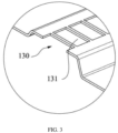
FIG. 3 is an enlarged view of a portion A shown inFIG. 2 . - In the drawings:
100, conductive unit; 110, positive-electrode connecting region; 120, negative-electrode connecting region; 121, circular notch; 130, first current-limiting region; 131, first through hole; 200, connecting member; 210, second current-limiting region; 211, second through hole. - In the description of the present disclosure, unless otherwise expressly specified and limited, terms "connected", "coupled", and "fixed" shall be interpreted broadly, such as fixed connection, detachable connection, being configured as an integral one-piece structure; mechanical connection, electrical connection; direct connection, indirect connection through an intermediate medium, internal communication between two elements, or an interaction between two elements. For any ordinary skilled person in the art, a specific meaning of the above terms in the context of the present disclosure shall be understood case by case.
- In the present disclosure, unless otherwise expressly specified and limited, a first feature "on" or "under" a second feature may include the first feature directly contacting the second feature, or the first feature indirectly contacting the second feature through an additional feature there between. In addition, the first feature "above", "over" and "on top of" the second feature includes the first feature being directly and diagonally above the second feature, or simply indicates that the first feature is horizontally higher than the second feature. The first feature "below", "under" and "beneath" the second feature includes the first feature being directly and diagonally below the second feature, or simply indicates that the first feature is horizontally lower than the second feature.
- In the description of the present disclosure, terms "up", "down", "left", "right", and other orientations or positional relationships are expressed based on the accompanying drawings. The terms are used for the purpose of description and for simplifying operations, but shall not be interpreted as indicating or implying that a device or an element referred to must have a particular orientation, be configured and be operating in a particular orientation. Therefore, the above terms shall not be interpreted as limiting the present disclosure. Furthermore, terms "first" and "second" are used only for distinguishing features while describing the features, and do not have special meanings.
- The present disclosure provides a connector for a large cylindrical battery, allowing large cylindrical batteries to be connected in series and in parallel with each other. Further, a short-circuit protection is configured to cut a current in time, reducing a loss caused by a short circuit and improving a service life and safety of the batteries.
- Exemplarily, as shown in
FIG. 1 , the connector for the large cylindrical battery is configured for a large cylindrical battery whose positive electrode and negative electrode are located on a same side and includes a plurality ofconductive units 100. Each of the plurality ofconductive units 100 includes a positive-electrode connecting region 110 and a negative-electrode connecting region 120. The positive-electrode connecting region 110 is configured to connect positive electrodes of two adjacent large cylindrical batteries, and the negative-electrode connecting region 120 is configured to connect negative electrodes of two adjacent large cylindrical batteries, allowing the two adjacent large cylindrical batteries to be connected in series or in parallel with each other. A first current-limitingregion 130 is arranged between the positive-electrode connecting region 110 and the negative-electrode connecting region 120. When a temperature of a circuit is excessively high due to an extreme situation such as a short circuit, the first current-limitingregion 130 itself may be heated and fused to cut a current between the two adjacent large cylindrical batteries, a current loop may be cut, such that the first current-limitingregion 130 may protect the circuit. Adjacentconductive units 100 are electrically connected to each other by a connectingmember 200. - The first current-limiting
region 130 is arranged between the positive-electrode connecting region 110 and the negative-electrode connecting region 120. In this way, when the temperature in the circuit is excessively high, the first current-limitingregion 130 may be fused to protect large cylindrical batteries that are connected in series by an individualconductive unit 100. Compared to related art where a plurality of batteries are configured with one fuse, by configuring the above-mentioned connector for the large cylindrical battery of the present disclosure, a damaged large cylindrical battery may be identified quickly after the first current-limitingregion 130 is fused, such that labor may be saved, operating-hours may be reduced, and subsequent maintenance and replacement may be performed easily. By configuring theconnection member 200 to connect the adjacentconductive units 100, the large cylindrical batteries may be connected in parallel with each other. - Exemplarily, a second current-limiting
region 210 can be arranged on the connectingmember 200. When the temperature of the circuit is excessively high due to an extreme situation such as the short circuit, the second current-limitingregion 120 itself may be heated and fused to quickly cut a current between adjacent sets of large cylindrical batteries, the current loop may be cut, such that the second current-limitingregion 210 may protect the circuit, and the safety of the large cylindrical batteries may be improved. - Exemplarily, as shown in
FIG. 1 , in an embodiment, a first throughhole 131 may be defined in the first current-limitingregion 130, allowing a cross-sectional area of the first current-limitingregion 130 to be less than each of a cross-sectional area of the positive-electrode connecting region 110 and a cross-sectional area of the negative-electrode connecting region 120. When the temperature of the circuit is excessively high due to an extreme situation such as the short circuit, the first current-limitingregion 130 may be melt and fused, due to concentrated thermal stresses, to cut the current loop, such that the circuit may be protected. Similarly, a second throughhole 211 may be defined in the second current-limitingregion 210, allowing a cross-sectional area of the second current-limitingregion 210 to be less than a cross-sectional area of the connectingmember 200. When the temperature of the circuit is excessively high due to an extreme situation such as the short circuit, the second current-limitingregion 210 may be melt and fused, due to concentrated thermal stresses, to cut the current loop, such that the circuit may be protected. - Exemplarily, as shown in
FIG. 1 , a plurality of first throughholes 131 may be arranged along a width direction of theconductive unit 100 and may be spaced apart from each other. A current-limiting segment may be disposed between adjacent two of the plurality of first throughholes 131. In the present embodiment, as shown inFIG. 1 , arrangement of the plurality of first throughholes 131 may start from an edge of the first current-limitingregion 130 along the width direction, i.e., the starting one of the plurality of first throughholes 131 serves as a notch at the edge of the first current-limitingregion 130. The arrangement of the plurality of first throughholes 131 may be terminated, based on the width of the first current-limitingregion 130, at another notch or a current-limiting segment disposed at the other edge of the first current-limitingregion 130 along the width direction. In another embodiment, the arrangement of the plurality of first throughholes 131 may start from a current-limiting segment disposed at the edge of the first current-limitingregion 130 along the width direction. Alternatively, in the present embodiment, the plurality of first throughholes 131 are spaced apart from each other, and distances between every two adjacent first through holes are the same. All current limiting segments have a same cross-sectional area to avoid a situation that the current loop is cut due to different cross-sectional areas of the current limiting segments, where a current limiting segment having a smaller cross-sectional area may be fuse earlier than a fusing current being reached. In this way, the circuit may operate normally. A size of a current limiting segment between adjacent first throughholes 131 may be determined based on actual needs. - Alternatively, a metal having a low melting point, such as tin, may be arranged on the first current-limiting
region 130. Exemplarily, the metal having the low melting point may be arranged on the current limiting segment. When the circuit is in an extreme situation such as having the short circuit, the current in the circuit increases rapidly. The increase of the current may cause the temperature of the circuit to increase. When the temperature reaches a value to allow the metal having the low melting point to melt, an alloying process begins, a resistance of a region where the alloy is located may be increased, enabling a temperature at the current limiting segment to be increased rapidly, such that the metal having the low melting point may melt within milliseconds, the current may be cut, and the circuit may be protected. The metal having the low melting point may be fixed in the first current-limitingregion 130 by welding, or arranged in the first current-limitingregion 130 by other means. The means of arranging the first current-limitingregion 130 may be determined based on actual needs. By defining the first throughholes 131 and the metal having the low melting point in the first current-limitingregion 130, the circuit may be protected in two manners, and safety of the large cylindrical battery may be improved. - Alternatively, the metal having the low melting point, such as tin, may be arranged on the second current-limiting
region 210. When the circuit is in an extreme situation such as having the short circuit, the current in the circuit increases rapidly. The increase of the current may cause the temperature of the circuit to increase. When the temperature reaches a value to allow the metal having the low melting point to melt, the alloying process begins, the resistance of the region where the alloy is located may be increased, enabling a temperature at the second current-limitingregion 210 to be increased rapidly, such that the metal having the low melting point may melt within milliseconds, the current may be cut, and the circuit may be protected. The metal having the low melting point may be fixed in the second current-limitingregion 210 by welding, or arranged in the second current-limitingregion 210 by other means. The means of arranging the first current-limitingregion 130 may be determined based on actual needs. By defining the second throughholes 211 and the metal having the low melting point in the second current-limitingregion 210, the circuit may be protected in two manners, and safety of the large cylindrical battery may be improved. - Exemplarily, in another embodiment, the first current-limiting
region 130 may be thin, such that a thickness of the first current-limitingregion 130 is less than a thickness of the rest of theconductive unit 100. That is, the cross-sectional area of the first current-limitingregion 130 is less than a cross-sectional area of the rest of theconductive unit 100. When the circuit is in an extreme situation such as having the short circuit, the first current-limitingregion 130 may be fused due to concentrated thermal stresses since having a relatively small cross-sectional area, such that the current loop is cut, and a core and the circuit may be protected. Of course, the second current-limitingregion 210 may be thin, such that a thickness of the second current-limitingregion 210 is less than a thickness of the connectingmember 200. That is, a cross-sectional area of the second current-limitingregion 210 is less than a cross-sectional area of the connectingmember 200. When the circuit is in an extreme situation such as having the short circuit, the second current-limitingregion 210 may be fused due to concentrated thermal stresses since having a relatively small cross-sectional area, such that the current loop is cut, and a core and the circuit may be protected. The thickness of the first current-limitingregion 130 and the thickness of the second current-limitingregion 210 may be determined based on the fusing requirements. - In some embodiments, the thickness of the first current-limiting region may be 0.8mm to 1.6mm, exemplarily may be 0.8mm, 1.0mm, 1.2mm, 1.4mm, 1.6mm, and so on. The thickness of the first current-limiting region may be determined based on a current limit value of the current and a need for a circuit fusing current. It is conceivable that the thickness of the second current-limiting
region 210 may also be 0.8mm to 1.6mm, exemplarily may be 0.8mm, 1.0mm, 1.2mm, 1.4mm, 1.6mm, and so on. The thickness of the first current-limiting region may be determined based on fusing requirements. - Alternatively, as shown in
FIG. 2 andFIG. 3 , in an embodiment, theconductive unit 100 may be configured as a protruded structure, and the first current-limitingregion 130 may be disposed on a protruded portion of the protruded structure. On one hand, by disposing the first current-limitingregion 130 on the protruded portion, a fusing space of the first current-limitingregion 130 can be increased, such that the first current-limiting region can be fused more quickly, and the large cylindrical battery may be prevented from being damaged by a high temperature generated when the first current-limitingregion 130 is fused. On the other hand, there is a certain height difference between the positive electrode and the negative electrode of the large cylindrical battery, and while the battery module is being used, the plurality of large cylindrical batteries may slightly shake in relative to each other. Theconductive unit 100 is generally connected to the positive electrode and the negative electrode of the large cylindrical battery by welding. As the large cylindrical batteries shake, the above-mentioned connector for the large cylindrical battery may be stretched or compressed. Therefore, theconductive unit 100 is configured as the protruded structure to provide a certain buffer space for the connector of the large cylindrical battery, preventing the connector of the large cylindrical battery from being broken, and improving operating reliability of the connector of the large cylindrical battery. Alternatively, the protruded structure is a "JL"-shaped structure.In another embodiment, theconductive unit 100 may be configured as a Z-shaped structure, and the first current-limitingregion 130 may be arranged on an inclined part of the Z-shaped structure. In other embodiments, theconductive unit 100 may be arranged with a wavy structure, and the first current-limitingregion 130 may be arranged on the wavy structure. The configuration of theconductive unit 100 may be determined based on actual needs. - Alternatively, in an embodiment, the
conductive unit 100 may be made of copper. The copper is highly electrically conductive, highly thermally conductive, and resistant to corrosion. In other embodiments, other conductive metals may be configured, and may be determined based on actual needs. - Exemplarily, the positive electrode and the negative electrode of the large cylindrical battery are located on a same side, the positive electrode is a cylindrical protrusion located at a middle of the battery, and the negative electrode is around the protrusion. Therefore, an arc-shaped notch, which matches a positive electrode post of the large cylindrical battery, may be arranged in the negative-
electrode connecting region 120. This structure may increase a connection area between the negative-electrode connecting region 120 and the negative electrode of the large cylindrical battery, such that reliability of the connection between the negative-electrode connecting region 120 and the negative electrode of the large cylindrical battery, improving the operating reliability of the connector of the large cylindrical battery. - Exemplarily, the positive-
electrode connecting region 110 may include an arc-shaped section, and an outer edge of the arc-shaped section partially coincides with an outer edge of the positive electrode post of the large cylindrical battery. On one hand, the positive-electrode connecting region 110 may be positioned in advance based on the positive electrode post of the large cylindrical battery, reducing difficulty of manual welding. On the other hand, while a connection area between the positive electrode post of the large cylindrical battery and the positive-electrode connecting region 110 is maximized, a size of the positive-electrode connecting region 110 may be reduced, materials may be saved, and costs may be reduced. - The first current-limiting
region 130 and the second current-limitingregion 210 are arranged, the first throughholes 131 are defined in the first current-limitingregion 130, and the second throughholes 211 are defined in the second current-limitingregion 210. In this way, the cross-sectional area of the first current-limitingregion 130 is less than the cross-sectional area of theconductive unit 100 along the width direction. The cross-sectional area of the second current-limitingregion 210 is less than the cross-sectional area of the connectingmember 200. When the circuit is in the extreme condition such as having the short circuit, the first current-limitingregion 130 and the second current-limitingregion 210 may be fused due to concentrated thermal stresses, such that large cylindrical batteries may be quickly disconnected from each other, the circuit loop of the entire battery may be cut in time. In this way, the large cylindrical battery may be protected, a thermal runaway loss may be reduced, and costs may be saved. In addition, a large cylindrical battery that cannot operate normally may be identified quickly, facilitating subsequent maintenance and replacement. - The present disclosure further provides a battery module including large cylindrical batteries and a connector of large cylindrical batteries as described in the above, wherein the positive electrode and the negative electrode of each of the large cylindrical batteries are located on the same side.
- Exemplarily, in an embodiment, a plurality of large cylindrical batteries are arranged into a plurality of sets, and large cylindrical batteries of connected sets are misaligned with each other. Correspondingly, adjacent
conductive units 100 are misaligned with each other , such that an assembling space may be reduced, a size of the above-described battery module may be reduced, and costs may be reduced. - The present disclosure further provides a battery pack including the battery module as described in the above.
Claims (15)
- A connector of a large cylindrical battery, configured for a large cylindrical battery having a positive electrode and a negative electrode on a same side, and the connector comprising a plurality of conductive units (100);wherein each of the plurality of conductive units (100) comprises a positive-electrode connecting region (110), a negative-electrode connecting region (120), and a first current-limiting region (130) arranged between the positive-electrode connecting region (110) and the negative-electrode connecting region (120);when a temperature of a circuit is excessively high, the first current-limiting region (130) is fused; andadjacent conductive units (100) of the plurality of conductive units (100) are electrically connected to each other by a connecting member (200).
- The connector of a large cylindrical battery according to claim 1, wherein a second current-limiting region (210) is arranged on the connecting member (200); and when the temperature of the circuit is excessively high, the second current-limiting region (120) is fused.
- The connector of a large cylindrical battery according to claim 2, wherein a first through hole (131) is defined in the first current-limiting region (130), and a second through hole (211) is defined in the second current-limiting region (210).
- The connector of a large cylindrical battery according to claim 3, wherein the number of first through holes (131) is more than one; the more than one first through holes (131) are arranged along a width direction of each of the plurality of conductive units (100) and are spaced apart from each other.
- The connector of a large cylindrical battery according to claim 3, wherein a metal having a low melting point is arranged on at least one of the first current-limiting region (130) and the second current-limiting region (210).
- The connector of a large cylindrical battery according to claim 2, wherein the connector is configured to meet at least one of the following:for each of the plurality of conductive units (100), a thickness of the first current-limiting region (130) is less than a thickness of the conductive unit (100); anda thickness of the second current-limiting region (210) is less than a thickness of the connecting member (200).
- The connector of a large cylindrical battery according to claim 6, wherein the thickness of the first current-limiting region (130) is 0.8mm to 1.6mm.
- The connector of a large cylindrical battery according to claim 1, wherein each of the plurality of conductive units (100) is configured as a protruded structure, and a protruded portion of the protruded structure serves as the first current-limiting region (130).
- The connector of a large cylindrical battery according to claim 1, wherein each of the plurality of conductive units (100) is configured as a Z-shaped structure, and an inclined part of the Z-shaped structure serves as the first current-limiting region (130).
- The connector of a large cylindrical battery according to claim 1, wherein each of the plurality of conductive units (100) is arranged with a wavy structure, and the first current-limiting region (130) is arranged on the wavy structure.
- The connector of a large cylindrical battery according to claim 1, wherein the negative-electrode connecting region (120) comprises an arc-shaped notch that matches a positive electrode post of the large cylindrical battery.
- The connector of a large cylindrical battery according to claim 1, wherein the positive-electrode connecting region (110) comprises an arc-shaped section, and an outer edge of the arc-shaped section partially coincides with an outer edge of a positive electrode post of the large cylindrical battery.
- A battery module, comprising a plurality of large cylindrical batteries and the connector of the large cylindrical battery according to any one of claims 1 to 12, wherein a positive electrode and a negative electrode of each of the plurality of large cylindrical batteries are located on a same side.
- The battery module according to claim 13, wherein the plurality of large cylindrical batteries are arranged into a plurality of sets, large cylindrical batteries of adjacent sets of the plurality of sets are misaligned with each other, and adjacent conductive units (100) of the plurality of conductive units (100) are misaligned with each other.
- A battery pack, comprising the battery module according to claim 13 or claim 14.
Applications Claiming Priority (2)
| Application Number | Priority Date | Filing Date | Title |
|---|---|---|---|
| CN202220226680.9U CN217158544U (en) | 2022-01-25 | 2022-01-25 | A cylindrical battery connecting piece, a battery module and a battery pack |
| PCT/CN2022/129989 WO2023142586A1 (en) | 2022-01-25 | 2022-11-04 | Large cylindrical battery connecting sheet, battery module and battery pack |
Publications (3)
| Publication Number | Publication Date |
|---|---|
| EP4243185A1 true EP4243185A1 (en) | 2023-09-13 |
| EP4243185A4 EP4243185A4 (en) | 2024-04-10 |
| EP4243185B1 EP4243185B1 (en) | 2026-03-11 |
Family
ID=87314586
Family Applications (1)
| Application Number | Title | Priority Date | Filing Date |
|---|---|---|---|
| EP22829535.8A Active EP4243185B1 (en) | 2022-01-25 | 2022-11-04 | Large cylindrical battery connecting sheet, battery module and battery pack |
Country Status (4)
| Country | Link |
|---|---|
| US (2) | US12113248B2 (en) |
| EP (1) | EP4243185B1 (en) |
| JP (2) | JP7675180B2 (en) |
| KR (1) | KR102924862B1 (en) |
Families Citing this family (3)
| Publication number | Priority date | Publication date | Assignee | Title |
|---|---|---|---|---|
| KR102924862B1 (en) * | 2022-01-25 | 2026-02-09 | 이브 파워 코포레이션 리미티드 | Large cylindrical battery connection sheets, battery modules and battery packs |
| WO2025077342A1 (en) * | 2023-10-11 | 2025-04-17 | 湖北亿纬动力有限公司 | Busbar assembly, battery module and battery pack |
| US20250357639A1 (en) * | 2024-05-14 | 2025-11-20 | Eve Energy Co., Ltd. | Bus bar, battery module and battery pack |
Family Cites Families (18)
| Publication number | Priority date | Publication date | Assignee | Title |
|---|---|---|---|---|
| JP3942138B2 (en) * | 2000-08-11 | 2007-07-11 | Necトーキン株式会社 | Sealed battery |
| CN1901252B (en) * | 2005-07-18 | 2010-05-05 | 比亚迪股份有限公司 | Battery connection sheet and battery group using said battery connection sheet |
| BRPI0911250A2 (en) * | 2008-04-14 | 2015-10-06 | A123 Systems Inc | Flexible voltage housed battery module design |
| US8361646B2 (en) * | 2010-03-15 | 2013-01-29 | Electronvault, Inc. | Modular interconnection system |
| CN104134774A (en) * | 2014-07-16 | 2014-11-05 | 苏州宇量电池有限公司 | Soldering lug having fusing function for connecting batteries |
| CN107305938A (en) * | 2016-04-25 | 2017-10-31 | 比亚迪股份有限公司 | Cell connector, battery modules and electrokinetic cell bag |
| CN116435672A (en) * | 2017-09-20 | 2023-07-14 | 松下知识产权经营株式会社 | battery module |
| JP7320165B2 (en) * | 2018-03-23 | 2023-08-03 | パナソニックエナジー株式会社 | secondary battery |
| CN110416480A (en) | 2018-04-27 | 2019-11-05 | 博世汽车部件(苏州)有限公司 | Battery pack and its electrode conductor |
| CN109037572A (en) * | 2018-07-26 | 2018-12-18 | 东莞市中质电子科技有限公司 | A kind of new energy battery modules conduction connecting structure |
| CN109037569A (en) | 2018-07-26 | 2018-12-18 | 东莞市中质电子科技有限公司 | A kind of new energy battery modules electric connection structure |
| KR102598669B1 (en) * | 2018-09-11 | 2023-11-06 | 에스케이온 주식회사 | Bus bar and battery pack including the same |
| CN110911625B (en) | 2018-09-14 | 2025-02-21 | 宁德时代新能源科技股份有限公司 | Battery Module |
| KR102819127B1 (en) * | 2020-03-31 | 2025-06-12 | 주식회사 엘지에너지솔루션 | High Voltage Busbar Having Dissimilar Metals and Manufacturing Method Thereof |
| TWI881046B (en) * | 2020-04-09 | 2025-04-21 | 南韓商Lg新能源股份有限公司 | Battery module including module bus bar, battery pack including the same, and electronic device |
| CN213340646U (en) | 2020-09-23 | 2021-06-01 | 湖北亿纬动力有限公司 | Busbar and battery module |
| CN217158544U (en) | 2022-01-25 | 2022-08-09 | 湖北亿纬动力有限公司 | A cylindrical battery connecting piece, a battery module and a battery pack |
| KR102924862B1 (en) * | 2022-01-25 | 2026-02-09 | 이브 파워 코포레이션 리미티드 | Large cylindrical battery connection sheets, battery modules and battery packs |
-
2022
- 2022-11-04 KR KR1020237013949A patent/KR102924862B1/en active Active
- 2022-11-04 JP JP2023524877A patent/JP7675180B2/en active Active
- 2022-11-04 EP EP22829535.8A patent/EP4243185B1/en active Active
- 2022-12-30 US US18/091,416 patent/US12113248B2/en active Active
-
2024
- 2024-08-30 US US18/820,268 patent/US20240421453A1/en active Pending
-
2025
- 2025-04-25 JP JP2025072995A patent/JP2025100919A/en active Pending
Also Published As
| Publication number | Publication date |
|---|---|
| EP4243185B1 (en) | 2026-03-11 |
| JP7675180B2 (en) | 2025-05-12 |
| KR20230117333A (en) | 2023-08-08 |
| JP2025100919A (en) | 2025-07-03 |
| US20240421453A1 (en) | 2024-12-19 |
| US12113248B2 (en) | 2024-10-08 |
| JP2024507614A (en) | 2024-02-21 |
| US20230238673A1 (en) | 2023-07-27 |
| EP4243185A4 (en) | 2024-04-10 |
| KR102924862B1 (en) | 2026-02-09 |
Similar Documents
| Publication | Publication Date | Title |
|---|---|---|
| EP4243185A1 (en) | Large cylindrical battery connecting sheet, battery module and battery pack | |
| CN217158544U (en) | A cylindrical battery connecting piece, a battery module and a battery pack | |
| JP5356450B2 (en) | Secondary battery | |
| US8632911B2 (en) | Rechargeable battery | |
| CN103650209B (en) | Battery pack and connection strips applied to the battery pack | |
| CN111656559B (en) | Method for cutting off inflow current of battery system, power supply device provided with battery system, and power storage device | |
| CN114566764A (en) | Busbar subassembly and big cylinder power battery module | |
| EP3154107A1 (en) | Busbar | |
| CN217848246U (en) | Battery and battery pack | |
| KR101914564B1 (en) | Secondary battery with insulation member | |
| EP2823520A1 (en) | Battery cell connector | |
| KR102848633B1 (en) | Busbar assembly and cylindrical power battery module | |
| KR20140028943A (en) | Secondary battery with improved safety | |
| EP4243187A1 (en) | Battery connector, battery module and battery pack | |
| CN118472562B (en) | A bus, a battery module and a battery pack | |
| CN218602505U (en) | Lithium ion battery integrated structure | |
| JPWO2019150706A1 (en) | Short current cutoff method for battery system and battery system, electric vehicle and power storage device equipped with battery system | |
| JPH1173941A (en) | Battery safety device | |
| EP3989356B1 (en) | Battery, battery module and battery pack | |
| CN213071296U (en) | Multi-fold U-shaped buffer device for connecting battery cells | |
| KR102715826B1 (en) | Protection device, battery pack | |
| CN222883796U (en) | Bus, battery module and battery pack | |
| CN219801207U (en) | Square lithium cell connects PACK device in parallel | |
| WO2024198025A1 (en) | Busbar, battery module, and battery pack | |
| EP3373364A1 (en) | Connector and safety assembly, cell arrangement, battery, and apparatus |
Legal Events
| Date | Code | Title | Description |
|---|---|---|---|
| STAA | Information on the status of an ep patent application or granted ep patent |
Free format text: STATUS: UNKNOWN |
|
| STAA | Information on the status of an ep patent application or granted ep patent |
Free format text: STATUS: THE INTERNATIONAL PUBLICATION HAS BEEN MADE |
|
| PUAI | Public reference made under article 153(3) epc to a published international application that has entered the european phase |
Free format text: ORIGINAL CODE: 0009012 |
|
| STAA | Information on the status of an ep patent application or granted ep patent |
Free format text: STATUS: REQUEST FOR EXAMINATION WAS MADE |
|
| 17P | Request for examination filed |
Effective date: 20230306 |
|
| AK | Designated contracting states |
Kind code of ref document: A1 Designated state(s): AL AT BE BG CH CY CZ DE DK EE ES FI FR GB GR HR HU IE IS IT LI LT LU LV MC ME MK MT NL NO PL PT RO RS SE SI SK SM TR |
|
| A4 | Supplementary search report drawn up and despatched |
Effective date: 20240307 |
|
| RIC1 | Information provided on ipc code assigned before grant |
Ipc: H01M 50/502 20210101AFI20240301BHEP |
|
| STAA | Information on the status of an ep patent application or granted ep patent |
Free format text: STATUS: EXAMINATION IS IN PROGRESS |
|
| 17Q | First examination report despatched |
Effective date: 20241218 |
|
| DAV | Request for validation of the european patent (deleted) | ||
| DAX | Request for extension of the european patent (deleted) | ||
| GRAP | Despatch of communication of intention to grant a patent |
Free format text: ORIGINAL CODE: EPIDOSNIGR1 |
|
| STAA | Information on the status of an ep patent application or granted ep patent |
Free format text: STATUS: GRANT OF PATENT IS INTENDED |
|
| INTG | Intention to grant announced |
Effective date: 20251020 |
|
| GRAS | Grant fee paid |
Free format text: ORIGINAL CODE: EPIDOSNIGR3 |
|
| GRAA | (expected) grant |
Free format text: ORIGINAL CODE: 0009210 |
|
| STAA | Information on the status of an ep patent application or granted ep patent |
Free format text: STATUS: THE PATENT HAS BEEN GRANTED |
|
| AK | Designated contracting states |
Kind code of ref document: B1 Designated state(s): AL AT BE BG CH CY CZ DE DK EE ES FI FR GB GR HR HU IE IS IT LI LT LU LV MC ME MK MT NL NO PL PT RO RS SE SI SK SM TR |
|
| REG | Reference to a national code |
Ref country code: CH Ref legal event code: F10 Free format text: ST27 STATUS EVENT CODE: U-0-0-F10-F00 (AS PROVIDED BY THE NATIONAL OFFICE) Effective date: 20260311 Ref country code: GB Ref legal event code: FG4D |
|
| REG | Reference to a national code |
Ref country code: DE Ref legal event code: R096 Ref document number: 602022032265 Country of ref document: DE |
|
| REG | Reference to a national code |
Ref country code: IE Ref legal event code: FG4D |