EP4243161A1 - Cooling plate assembly, liquid cooling module and battery pack - Google Patents
Cooling plate assembly, liquid cooling module and battery pack Download PDFInfo
- Publication number
- EP4243161A1 EP4243161A1 EP22826789.4A EP22826789A EP4243161A1 EP 4243161 A1 EP4243161 A1 EP 4243161A1 EP 22826789 A EP22826789 A EP 22826789A EP 4243161 A1 EP4243161 A1 EP 4243161A1
- Authority
- EP
- European Patent Office
- Prior art keywords
- flow channel
- cooling
- connector
- liquid
- cooling plate
- Prior art date
- Legal status (The legal status is an assumption and is not a legal conclusion. Google has not performed a legal analysis and makes no representation as to the accuracy of the status listed.)
- Pending
Links
Images



Classifications
-
- H—ELECTRICITY
- H01—ELECTRIC ELEMENTS
- H01M—PROCESSES OR MEANS, e.g. BATTERIES, FOR THE DIRECT CONVERSION OF CHEMICAL ENERGY INTO ELECTRICAL ENERGY
- H01M10/00—Secondary cells; Manufacture thereof
- H01M10/60—Heating or cooling; Temperature control
- H01M10/65—Means for temperature control structurally associated with the cells
- H01M10/655—Solid structures for heat exchange or heat conduction
- H01M10/6556—Solid parts with flow channel passages or pipes for heat exchange
-
- F—MECHANICAL ENGINEERING; LIGHTING; HEATING; WEAPONS; BLASTING
- F28—HEAT EXCHANGE IN GENERAL
- F28D—HEAT-EXCHANGE APPARATUS, NOT PROVIDED FOR IN ANOTHER SUBCLASS, IN WHICH THE HEAT-EXCHANGE MEDIA DO NOT COME INTO DIRECT CONTACT
- F28D1/00—Heat-exchange apparatus having stationary conduit assemblies for one heat-exchange medium only, the media being in contact with different sides of the conduit wall, in which the other heat-exchange medium is a large body of fluid, e.g. domestic or motor car radiators
- F28D1/02—Heat-exchange apparatus having stationary conduit assemblies for one heat-exchange medium only, the media being in contact with different sides of the conduit wall, in which the other heat-exchange medium is a large body of fluid, e.g. domestic or motor car radiators with heat-exchange conduits immersed in the body of fluid
- F28D1/04—Heat-exchange apparatus having stationary conduit assemblies for one heat-exchange medium only, the media being in contact with different sides of the conduit wall, in which the other heat-exchange medium is a large body of fluid, e.g. domestic or motor car radiators with heat-exchange conduits immersed in the body of fluid with tubular conduits
- F28D1/053—Heat-exchange apparatus having stationary conduit assemblies for one heat-exchange medium only, the media being in contact with different sides of the conduit wall, in which the other heat-exchange medium is a large body of fluid, e.g. domestic or motor car radiators with heat-exchange conduits immersed in the body of fluid with tubular conduits the conduits being straight
- F28D1/0535—Heat-exchange apparatus having stationary conduit assemblies for one heat-exchange medium only, the media being in contact with different sides of the conduit wall, in which the other heat-exchange medium is a large body of fluid, e.g. domestic or motor car radiators with heat-exchange conduits immersed in the body of fluid with tubular conduits the conduits being straight the conduits having a non-circular cross-section
- F28D1/05358—Assemblies of conduits connected side by side or with individual headers, e.g. section type radiators
-
- F—MECHANICAL ENGINEERING; LIGHTING; HEATING; WEAPONS; BLASTING
- F28—HEAT EXCHANGE IN GENERAL
- F28F—DETAILS OF HEAT-EXCHANGE AND HEAT-TRANSFER APPARATUS, OF GENERAL APPLICATION
- F28F1/00—Tubular elements; Assemblies of tubular elements
- F28F1/006—Tubular elements; Assemblies of tubular elements with variable shape, e.g. with modified tube ends, with different geometrical features
-
- F—MECHANICAL ENGINEERING; LIGHTING; HEATING; WEAPONS; BLASTING
- F28—HEAT EXCHANGE IN GENERAL
- F28F—DETAILS OF HEAT-EXCHANGE AND HEAT-TRANSFER APPARATUS, OF GENERAL APPLICATION
- F28F1/00—Tubular elements; Assemblies of tubular elements
- F28F1/02—Tubular elements of cross-section which is non-circular
- F28F1/025—Tubular elements of cross-section which is non-circular with variable shape, e.g. with modified tube ends, with different geometrical features
-
- F—MECHANICAL ENGINEERING; LIGHTING; HEATING; WEAPONS; BLASTING
- F28—HEAT EXCHANGE IN GENERAL
- F28F—DETAILS OF HEAT-EXCHANGE AND HEAT-TRANSFER APPARATUS, OF GENERAL APPLICATION
- F28F9/00—Casings; Header boxes; Auxiliary supports for elements; Auxiliary members within casings
- F28F9/02—Header boxes; End plates
- F28F9/0246—Arrangements for connecting header boxes with flow lines
-
- F—MECHANICAL ENGINEERING; LIGHTING; HEATING; WEAPONS; BLASTING
- F28—HEAT EXCHANGE IN GENERAL
- F28F—DETAILS OF HEAT-EXCHANGE AND HEAT-TRANSFER APPARATUS, OF GENERAL APPLICATION
- F28F9/00—Casings; Header boxes; Auxiliary supports for elements; Auxiliary members within casings
- F28F9/26—Arrangements for connecting different sections of heat-exchange elements, e.g. of radiators
-
- H—ELECTRICITY
- H01—ELECTRIC ELEMENTS
- H01M—PROCESSES OR MEANS, e.g. BATTERIES, FOR THE DIRECT CONVERSION OF CHEMICAL ENERGY INTO ELECTRICAL ENERGY
- H01M10/00—Secondary cells; Manufacture thereof
- H01M10/60—Heating or cooling; Temperature control
- H01M10/61—Types of temperature control
- H01M10/613—Cooling or keeping cold
-
- H—ELECTRICITY
- H01—ELECTRIC ELEMENTS
- H01M—PROCESSES OR MEANS, e.g. BATTERIES, FOR THE DIRECT CONVERSION OF CHEMICAL ENERGY INTO ELECTRICAL ENERGY
- H01M10/00—Secondary cells; Manufacture thereof
- H01M10/60—Heating or cooling; Temperature control
- H01M10/61—Types of temperature control
- H01M10/617—Types of temperature control for achieving uniformity or desired distribution of temperature
-
- H—ELECTRICITY
- H01—ELECTRIC ELEMENTS
- H01M—PROCESSES OR MEANS, e.g. BATTERIES, FOR THE DIRECT CONVERSION OF CHEMICAL ENERGY INTO ELECTRICAL ENERGY
- H01M10/00—Secondary cells; Manufacture thereof
- H01M10/60—Heating or cooling; Temperature control
- H01M10/62—Heating or cooling; Temperature control specially adapted for specific applications
- H01M10/625—Vehicles
-
- H—ELECTRICITY
- H01—ELECTRIC ELEMENTS
- H01M—PROCESSES OR MEANS, e.g. BATTERIES, FOR THE DIRECT CONVERSION OF CHEMICAL ENERGY INTO ELECTRICAL ENERGY
- H01M10/00—Secondary cells; Manufacture thereof
- H01M10/60—Heating or cooling; Temperature control
- H01M10/64—Heating or cooling; Temperature control characterised by the shape of the cells
- H01M10/643—Cylindrical cells
-
- H—ELECTRICITY
- H01—ELECTRIC ELEMENTS
- H01M—PROCESSES OR MEANS, e.g. BATTERIES, FOR THE DIRECT CONVERSION OF CHEMICAL ENERGY INTO ELECTRICAL ENERGY
- H01M10/00—Secondary cells; Manufacture thereof
- H01M10/60—Heating or cooling; Temperature control
- H01M10/64—Heating or cooling; Temperature control characterised by the shape of the cells
- H01M10/647—Prismatic or flat cells, e.g. pouch cells
-
- H—ELECTRICITY
- H01—ELECTRIC ELEMENTS
- H01M—PROCESSES OR MEANS, e.g. BATTERIES, FOR THE DIRECT CONVERSION OF CHEMICAL ENERGY INTO ELECTRICAL ENERGY
- H01M10/00—Secondary cells; Manufacture thereof
- H01M10/60—Heating or cooling; Temperature control
- H01M10/65—Means for temperature control structurally associated with the cells
- H01M10/655—Solid structures for heat exchange or heat conduction
- H01M10/6554—Rods or plates
-
- H—ELECTRICITY
- H01—ELECTRIC ELEMENTS
- H01M—PROCESSES OR MEANS, e.g. BATTERIES, FOR THE DIRECT CONVERSION OF CHEMICAL ENERGY INTO ELECTRICAL ENERGY
- H01M10/00—Secondary cells; Manufacture thereof
- H01M10/60—Heating or cooling; Temperature control
- H01M10/65—Means for temperature control structurally associated with the cells
- H01M10/655—Solid structures for heat exchange or heat conduction
- H01M10/6554—Rods or plates
- H01M10/6555—Rods or plates arranged between the cells
-
- H—ELECTRICITY
- H01—ELECTRIC ELEMENTS
- H01M—PROCESSES OR MEANS, e.g. BATTERIES, FOR THE DIRECT CONVERSION OF CHEMICAL ENERGY INTO ELECTRICAL ENERGY
- H01M10/00—Secondary cells; Manufacture thereof
- H01M10/60—Heating or cooling; Temperature control
- H01M10/65—Means for temperature control structurally associated with the cells
- H01M10/655—Solid structures for heat exchange or heat conduction
- H01M10/6556—Solid parts with flow channel passages or pipes for heat exchange
- H01M10/6557—Solid parts with flow channel passages or pipes for heat exchange arranged between the cells
-
- H—ELECTRICITY
- H01—ELECTRIC ELEMENTS
- H01M—PROCESSES OR MEANS, e.g. BATTERIES, FOR THE DIRECT CONVERSION OF CHEMICAL ENERGY INTO ELECTRICAL ENERGY
- H01M10/00—Secondary cells; Manufacture thereof
- H01M10/60—Heating or cooling; Temperature control
- H01M10/65—Means for temperature control structurally associated with the cells
- H01M10/656—Means for temperature control structurally associated with the cells characterised by the type of heat-exchange fluid
- H01M10/6567—Liquids
-
- H—ELECTRICITY
- H01—ELECTRIC ELEMENTS
- H01M—PROCESSES OR MEANS, e.g. BATTERIES, FOR THE DIRECT CONVERSION OF CHEMICAL ENERGY INTO ELECTRICAL ENERGY
- H01M10/00—Secondary cells; Manufacture thereof
- H01M10/60—Heating or cooling; Temperature control
- H01M10/65—Means for temperature control structurally associated with the cells
- H01M10/656—Means for temperature control structurally associated with the cells characterised by the type of heat-exchange fluid
- H01M10/6567—Liquids
- H01M10/6568—Liquids characterised by flow circuits, e.g. loops, located externally to the cells or cell casings
-
- H—ELECTRICITY
- H01—ELECTRIC ELEMENTS
- H01M—PROCESSES OR MEANS, e.g. BATTERIES, FOR THE DIRECT CONVERSION OF CHEMICAL ENERGY INTO ELECTRICAL ENERGY
- H01M50/00—Constructional details or processes of manufacture of the non-active parts of electrochemical cells other than fuel cells, e.g. hybrid cells
- H01M50/20—Mountings; Secondary casings or frames; Racks, modules or packs; Suspension devices; Shock absorbers; Transport or carrying devices; Holders
- H01M50/204—Racks, modules or packs for multiple batteries or multiple cells
- H01M50/207—Racks, modules or packs for multiple batteries or multiple cells characterised by their shape
- H01M50/213—Racks, modules or packs for multiple batteries or multiple cells characterised by their shape adapted for cells having curved cross-section, e.g. round or elliptic
-
- F—MECHANICAL ENGINEERING; LIGHTING; HEATING; WEAPONS; BLASTING
- F28—HEAT EXCHANGE IN GENERAL
- F28D—HEAT-EXCHANGE APPARATUS, NOT PROVIDED FOR IN ANOTHER SUBCLASS, IN WHICH THE HEAT-EXCHANGE MEDIA DO NOT COME INTO DIRECT CONTACT
- F28D21/00—Heat-exchange apparatus not covered by any of the groups F28D1/00 - F28D20/00
- F28D2021/0019—Other heat exchangers for particular applications; Heat exchange systems not otherwise provided for
- F28D2021/0028—Other heat exchangers for particular applications; Heat exchange systems not otherwise provided for for cooling heat generating elements, e.g. for cooling electronic components or electric devices
- F28D2021/0029—Heat sinks
-
- F—MECHANICAL ENGINEERING; LIGHTING; HEATING; WEAPONS; BLASTING
- F28—HEAT EXCHANGE IN GENERAL
- F28D—HEAT-EXCHANGE APPARATUS, NOT PROVIDED FOR IN ANOTHER SUBCLASS, IN WHICH THE HEAT-EXCHANGE MEDIA DO NOT COME INTO DIRECT CONTACT
- F28D21/00—Heat-exchange apparatus not covered by any of the groups F28D1/00 - F28D20/00
- F28D2021/0019—Other heat exchangers for particular applications; Heat exchange systems not otherwise provided for
- F28D2021/0043—Other heat exchangers for particular applications; Heat exchange systems not otherwise provided for for fuel cells
-
- Y—GENERAL TAGGING OF NEW TECHNOLOGICAL DEVELOPMENTS; GENERAL TAGGING OF CROSS-SECTIONAL TECHNOLOGIES SPANNING OVER SEVERAL SECTIONS OF THE IPC; TECHNICAL SUBJECTS COVERED BY FORMER USPC CROSS-REFERENCE ART COLLECTIONS [XRACs] AND DIGESTS
- Y02—TECHNOLOGIES OR APPLICATIONS FOR MITIGATION OR ADAPTATION AGAINST CLIMATE CHANGE
- Y02E—REDUCTION OF GREENHOUSE GAS [GHG] EMISSIONS, RELATED TO ENERGY GENERATION, TRANSMISSION OR DISTRIBUTION
- Y02E60/00—Enabling technologies; Technologies with a potential or indirect contribution to GHG emissions mitigation
- Y02E60/10—Energy storage using batteries
Definitions
- the application relates to the technical field of power batteries, such as a cooling plate assembly, a liquid cooling module and a battery pack.
- battery packs include cylindrical battery cells, and most of them are cooled by cooling pipes.
- common cooling pipes have two disadvantages: first, the cooling effect of the cylindrical battery cells located at the water inlet of the cooling pipe is good, while the cooling effect of the cylindrical battery cells located at the water outlet is poor, resulting in large temperature difference of the whole battery pack and uneven performance of different cylindrical battery cells; Second, the high difficulty in assembling the series cooling pipes leads to low yield; However, the space utilization rate of parallel cooling pipes is low, too many water inlet and outlet pipes cause large volume and occupy more space, which leads to low energy density of battery packs, and when side collision occurs, the risk of leakage is great, which leads to poor grouping ability and high cost of battery packs.
- the invention provides a cooling plate assembly, a liquid cooling module and a battery pack, which improve the temperature equalization performance of cylindrical battery cells, reduce the temperature difference between the upper and lower sides of the same cylindrical battery cell, reduce the temperature difference between cylindrical battery cells in the same row, reduce the temperature difference between cylindrical cells in different rows, and improve the cooling effect. It reduces the occupied space of the battery pack, improves the energy density of the battery pack, simplifies the structure and reduces the cost.
- the embodiment of the application provides a cooling plate assembly, which includes: a connector, wherein the connector is provided with at least one group of cooling flow channels, and each group of cooling flow channels includes a first flow channel and a second flow channel penetrating along a first direction, and the connector is provided with a third flow channel and a fourth flow channel penetrating along a second direction, wherein the first flow channel is communicated with the third channel, and the second channel is communicated with the fourth flow channel;
- Two groups of cooling pipe assemblies corresponding to each group of cooling flow channels are respectively arranged on both sides of the connector along the first direction, and the two groups of cooling pipe assemblies are respectively communicated with the first flow channel and the second channel located on the same side of the connector; of the third flow channel and the fourth flow channel, one is set as liquid inlet and the other is set as liquid outlet.
- the third flow channel and the fourth flow channel can be alternately arranged as liquid inlet and liquid outlet.
- each group of the cooling pipe assemblies includes: a first cooling pipe and a second cooling pipe, wherein the first end of the first cooling pipe is connected to the first flow channel, and the first end of the second cooling pipe is connected to the second flow channel; A liquid collecting pipe, the second end of the first cooling pipe and the second end of the second cooling pipe are respectively connected to the liquid collecting pipe.
- the first flow channel and the second flow channel are arranged along the third direction (Z) of the connector.
- a plurality of pipes are respectively arranged in the first cooling pipe and the second cooling pipe.
- the first cooling pipe and the second cooling pipe are both serpentine pipes, and the shapes of the serpentine pipes are all matched with the cylindrical battery cells.
- the outer surface of the cooling pipe assembly is provided with a heat conducting structure layer.
- two ends of the connector along the third direction (Z) are respectively provided with connecting members, and two of the connectors can be connected by the connecting members.
- the embodiment of the application provides a liquid cooling module, which includes the above-mentioned cooling plate assemblies, and the cooling plate assembly is provided with a plurality, wherein a plurality of cooling plate assemblies are sequentially connected in the second direction(Y) by the connector, the third flow channels of the plurality of cooling plate assemblies are communicated to form a first cooling liquid channel, and the fourth flow channels of the plurality of cooling plate assemblies are communicated to form a second cooling liquid channel.
- the connectors of two cooling plate assemblies located at the two ends of the plurality of cooling plate assemblies sequentially connected are defined as a head-end connector and a tail-end connector, respectively, Among the third flow channel and the fourth flow channel of the head-end connector and the third flow channel and the fourth flow channel of the tail-end connector, block the third flow channel of any one of the head-end connector and the tail-end connector and the fourth flow channel of any one of the head-end connector and the tail-end connector.
- one is arranged to communicate with the external liquid inlet device, and the other is arranged to communicate with the external liquid outlet device.
- the third flow channel and the fourth flow channel of the head-end connector are both blocked, and the third flow channel and the fourth flow channel of the tail-end connector are respectively communicated with the outside; or the third flow channel and the fourth flow channel of the tail-end connector are both blocked, and the third flow channel and the fourth flow channel of the head-end connector are respectively communicated with the outside.
- the connectors are also provided with plugs, and the plugs can respectively connect the third flow channels of two adjacent connectors and the fourth flow channels of two adjacent connectors.
- first ends of the third flow channel and the fourth flow channel on one side of one connector are respectively fixedly connected to the first ends of the plugs, and the second ends of the two plugs can be detachably connected to the second ends of the third flow channel and the fourth flow channel of the other connector.
- cooling plate assemblies when a plurality of the cooling plate assemblies are arranged along the third direction, two adjacent groups of the cooling plate assemblies are sequentially connected along the third direction through the connector.
- one embodiment of the present application provides a battery pack including the liquid cooling module mentioned above.
- the liquid cooling modules are provided with one or more groups, and when the liquid cooling modules are provided with multiple groups, multiple groups of the liquid cooling modules are arranged along the third direction (Z), and two adjacent groups of the liquid cooling modules are connected by the connector.
- a cooling plate assembly provided by the embodiment of the application when cooling, the cooling liquid enters the connector through the third flow channel, then flows back into the connector through the cooling pipe assemblies and the second flow channel, and is discharged through the fourth flow channel; In this process, cooling liquid is simultaneously introduced into the cooling pipe assemblies on both sides, so that the cylindrical battery cells on both sides are cooled at the same time, and the temperature uniformity of the cylindrical battery cells on both sides is improved.
- the liquid cooling module provided by the embodiment of the application reduces the temperature difference of the same row of cylindrical battery cells on both sides of the connector, and also reduces the temperature difference of the upper and lower sides of the cylindrical battery cells by adopting the above cooling plate assemblies; and a plurality of cooling plate assemblies are connected in parallel, so that the temperature difference between the cylindrical battery cells in different rows is reduced, thereby improving the temperature uniformity of the cylindrical battery cells and further improving the reliability.
- the cooling liquid passes through the external liquid storage device and enters the connector of the cooling plate assembly at the end through the third flow channel at the connector side of the cooling plate assembly at the end;
- the first cooling liquid channel formed by connecting a plurality of connectors through a plurality of the third flow channels is a cooling liquid inlet channel, and the cooling liquid sequentially enters the connectors of each cooling plate assembly;
- the cooling liquid entering the connector enters the first ends of the cooling pipe assemblies on both sides from the first flow channel of the connector; Then enters the connector from the second end of the cooling pipe assembly and the second flow channel, and the cooling liquid of a plurality of cooling plate assemblies sequentially flows out through the fourth flow channel;
- the second cooling liquid channel formed by connecting a plurality of connectors through the fourth flow channel is a cooling liquid outlet channel, and finally flows out from the fourth flow channel at the end;
- the fourth flow channel of the connector of the cooling plate assembly at the end is connected with an external collecting device, which is
- Each cooling plate assembly is connected by a connector, and the connector at the end is connected with an external liquid outlet device and an external collecting device respectively, and the first cooling liquid channel and the second cooling liquid channel formed by the connector connection enter and exit the cooling liquid, so that the traditional water inlet and outlet pipe structure is abandoned, the structure is simplified, the space is saved, the volume utilization rate of the battery pack is improved, the assembly difficulty is reduced, and the cost is reduced.
- the connector is arranged at the middle position of the liquid cooling module, so that the two sides of the battery pack do not have a long structure of the main water inlet and outlet pipe, and the risk of leakage of the cooling liquid when the battery pack is bumped sideways is reduced.
- the battery pack provided by the embodiment of the application has better cooling effect, improves the space utilization rate, can improve the energy density, simplify the structure, reduce the overall weight, is convenient to assemble, and has the advantage of rapid mass production.
- connection should be understood broadly, for example, they can be fixed connections, detachable connections or integrated; Can be mechanically connection or electrically connection; It can be directly connected or indirectly connected through an intermediate medium, and it can be the internal communication of two elements or the interaction between two elements.
- the first feature being “on” or “under” the second feature may include direct contact of the first feature and second feature, and may also include a case where the first feature is not directly contacted with the second feature, but is contacted with the second feature through additional features between them.
- the first feature being "on top of”, “above” or “on the surface of” the second feature includes that the first feature is right above or obliquely above the second feature, or merely indicates that the first feature level is higher than the second feature.
- the first feature being “at the bottom of", “below” or “under” the second feature includes a case where the first feature is directly below and obliquely below the second feature, or merely indicates that the first feature level is less than the second feature.
- the cooling plate assembly includes a connector 1 and a cooling pipe assembly 2.
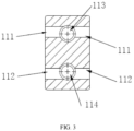
- the connector 1 is provided with at least one group of cooling flow channels, each group of which includes a first flow channel 111 and a second flow channel 112 penetrating along the first direction.
- the connector 1 is provided with a third flow channel 113 and a fourth flow channel 114 penetrating along the second direction, and the first flow channel 111 communicates with the third flow channel 113.
- Two groups of cooling pipe assemblies 2 arranged corresponding to each group of cooling flow channels, the two groups of cooling pipe assemblies 2 are respectively arranged on both sides of the connector 1 along the first direction, and the two groups of cooling pipe assemblies 2 are respectively communicated with the first flow channel 111 and the second flow channel 112 on the same side of the connector 1;
- One of the third flow channel 113 and the fourth flow channel 114 is set as liquid inlet, and the other is set as liquid outlet.
- the first direction is X
- the second direction is Y
- the third direction is Z
- the third direction, the first direction and the second direction are perpendicular to each other.
- the cooling liquid enters the connector 1 through the third flow channel 113, then enters the cooling pipe assemblies 2 on both sides through the first flow channel 111, then flows back into the connector 1 through the cooling pipe assemblies 2 and the second flow channel 112, and is discharged through the fourth flow channel 114.
- cooling liquid is simultaneously introduced into the cooling pipe assemblies 2 on both sides, so that the cylindrical battery cells on both sides are cooled at the same time, and the temperature uniformity of the cylindrical battery cells on both sides is improved.
- the third flow channel 113 and the fourth flow channel 114 can be alternately set as liquid inlet and liquid outlet, so that both ends of the cooling pipe assembly 2 can be alternately fed and discharged, and the cooling liquid can be alternately circulated in two directions, thus improving the temperature uniformity of the upper and lower sides of the cylindrical batter cell.
- the case of the fourth flow channel 114 is set for liquid inlet and the third flow channel 113 is set for liquid outlet can refer to the case of the third flow channel 113 for liquid inlet and the fourth flow channel 114 for liquid outlet, which will not be described again.
- the third flow channel 113 can be set as liquid inlet and the fourth flow channel 114 can be set as liquid outlet.
- the third channel 113 is set as liquid outlet and the fourth channel 114 is set as liquid inlet.
- the interval time of alternating liquid in and out can be set according to the working conditions, and there is no limit.
- the heat exchanged by each cylindrical battery cell is basically the same, and the heat exchanged by the upper and lower sides of the cylindrical battery cell is basically the same, which reduces the temperature difference and improves the reliability.
- the connector 1 is provided with a set of cooling flow channels, and the cooling plate assembly includes two groups of cooling pipe assemblies 2.
- the connector 1 may be provided with a plurality of groups of cooling flow channels. Taking two groups of cooling flow channels as an example, if the connector 1 is provided with two groups of cooling flow channels, four groups of cooling pipe assemblies 2 are correspondingly provided. For example, when two groups of cooling flow channels are arranged along the third direction, two groups of cooling pipe assemblies 2 are arranged along the third direction on each side, which can improve the temperature uniformity of the cylindrical battery cell.
- the cooling pipe assembly 2 includes a header pipe 23, a first cooling pipe 21 and a second cooling pipe 22, wherein the first end of the first cooling pipe 21 is connected to the first flow channel 111 and the first end of the second cooling pipe 22 is connected to the second flow channel 112; The second end of the first cooling pipe 21 and the second end of the second cooling pipe 22 are connected to the liquid collecting pipe 23, respectively.
- the cooling liquid flows through the first flow channel 111, the first cooling pipe 21, the liquid collecting pipe 23, the second cooling pipe 22 and the second flow channel 112 in turn, or vice versa, and the first cooling pipe 21 and the second cooling pipe 22 are connected through the liquid collecting pipe 23, so that the upper and lower sides of the cylindrical cell are simultaneously cooled.
- the cooling pipe assembly 2 is arranged separately, which is convenient for processing and assembly and reduces the cost.
- the cooling plate assembly 100 is divided into upper and lower parts along the third direction, which can cool the upper and lower sides of the cylindrical cell.
- the temperature will gradually increase due to the absorption of heat, so that the temperature of the cooling liquid in the liquid inlet part (the upper/lower side of the third party) of the cooling plate assembly 100 will gradually increase from one end close to the connector 1 to the direction away from the connector 1.
- the temperature of the cooling liquid in the outlet part gradually rises from one end far away from the connector 1 to the direction close to the connector 1, which can ensure the temperature uniformity of each cylindrical cell, for example, it is applicable to the case where the height of the cylindrical battery cells is high.
- the liquid collecting pipe 23 includes a fifth flow channel 231 and a sixth flow channel 232 which are communicated with each other, the first cooling pipe 21 is communicated with the fifth flow channel 231, and the second cooling pipe 22 is communicated with the sixth flow channel 232.
- the cooling liquid flows through the third flow channel 113, the first flow channel 111, the first cooling pipe 21, the fifth flow channel 231, the liquid collecting pipe 23, the sixth flow channel 232, the second cooling pipe 22, the second flow channel 112 and the fourth channel 114 in turn, or circulates in the opposite direction.
- the liquid collecting pipe 23 has a cavity structure, and the fifth flow channel 231 and the sixth flow channel 232 are communicated with each other through the cavity structure.
- the material is not limited, so long as it can be connected with the first cooling pipe 21 and the second cooling pipe 22 respectively.
- the liquid collecting pipe 23 can be communicated with the first cooling pipe 21 and the second cooling pipe 22 by welding, bonding, or other connection processes.
- the volume should be reduced as much as possible to save space, and it can be designed according to the internal space of the battery pack, without limitation.
- the first flow channel 111 and the second flow channel 112 are arranged along the third direction of the connector 1.
- the first cooling pipe 21 and the second cooling pipe 22 play the role of cooling the cylindrical battery cell, and they can be made of metal materials such as aluminum alloy, steel, copper alloy or materials with good thermal conductivity, without limitation.
- a plurality of pipes are respectively arranged in the first cooling pipe 21 and the second cooling pipe 22, which improves the uniformity of cooling liquid introduced into the first cooling pipe 21 and the second cooling pipe 22, and further improves the cooling effect along the third direction of the cylindrical battery cell.
- the cooling pipe assembly 2 and the connector 1 can be welded.
- the cooling pipe assembly 2 and the connector 1 are detachably connected to facilitate assembly;
- the cooling pipe assembly 2 may be located only on one side of the connector 1, and the first flow channel 111 and the second flow channel 112 on the other side may be blocked, so that the connector 1 is located at one end, which can be set according to the actual situation.
- the first cooling pipe and the second cooling pipe are both serpentine pipes, and the shape of the serpentine pipe is matched with the cylindrical battery cell, so that the contact area between the cooling pipe assembly 2 and the cylindrical battery cell is increased, and the cooling effect is improved.
- the first cooling pipe 21 and the second cooling pipe 22 are respectively provided with a plurality of circular arc surfaces, and the radian of the circular arc surfaces is matched with that of the cylindrical battery cell.
- the outer surface of the cooling pipe assembly 2 is provided with a heat-conducting structural layer, which can increase the bonding tightness between the cooling pipe assembly 2 and the cylindrical battery cell, so that the heat generated by the cylindrical cell is conducted to the cooling pipe assembly 2 through the heat-conducting structural layer, and the heat on the cooling pipe assembly 2 is taken away by the cooling liquid in its own pipeline, thus improving the cooling effect.
- the heat-conducting structural layer is made of heat-conducting structural adhesive, which has a good heat-conducting effect, improves the structural installation reliability, and plays a dual role of heat conduction and structural fixation.
- the two ends of the connector 1 in the third direction are respectively provided with connectors, and two connectors 1 can be connected by the connectors.
- two adjacent connectors 1 in the third direction are connected by connecting members, for example, the connecting members can be plugs and sockets, one end of the connector 1 is provided with a plug 12, and the other end is provided with a socket, and the two connectors 1 are connected by plug and socket.
- the connectors can be connected according to the relevant technologies, so that the two connectors 1 can be connected without limitation.
- a plurality of groups of cooling plate assemblies can be arranged along the third direction for cooling the cylindrical battery cell.
- a plurality of cooling plate assemblies are arranged in the second direction to form a layer, and when a layer of cylindrical battery cells is arranged, a layer of cooling plate assemblies is arranged to cool a layer of cylindrical battery cells;
- a layer of cooling plate assemblies is arranged to cool a layer of cylindrical battery cells;
- This embodiment also provides a liquid cooling module, as shown in FIG. 5 , which includes a plurality of cooling plate assemblies 100; For example, a plurality of cooling plate assemblies are sequentially connected in the second direction by the connector 1, the third flow channels 113 of the cooling plate assemblies are communicated to form a first cooling liquid channel, and the fourth flow channels 114 of the cooling plate assemblies are communicated to form a second cooling liquid channel.
- the cooling plate assemblies 100 are arranged near the cylindrical battery cells, and the cooling plate assemblies 100 can be arranged between two adjacent rows of cylindrical battery cells. Multiple groups of cooling plate assemblies 100 are connected in parallel through the connector 1, and the cooling plate assemblies 100 are arranged to cool multiple rows of cylindrical battery cells.
- the cooling liquid passes through the external liquid storage device and enters the connector 1 of the cooling plate assembly 100 at the end through the third flow channel 113 at one side of the connector 1.
- the first cooling flow channel formed by connecting a plurality of connectors 1 through a plurality of third flow channels 113 is a cooling inlet channel, and the cooling sequentially enters the connectors 1 of each cooling plate assembly 100;
- the cooling entering the connector 1 enters the first ends of the cooling pipe assemblies 2 on both sides from the first flow channel 111 of the connector 1; Then, it enters the connector 1 from the second end of the cooling pipe assembly 2 and the second flow channel 112, and the cooling liquid of each cooling plate assembly 100 flows out through the fourth flow channel 114 in turn.
- the second cooling liquid channel formed by connecting a plurality of connectors 1 through the fourth flow channel 114 is the cooling liquid outlet channel, and the cooling liquid flows out from the fourth flow channel 114 at the end.
- the fourth flow channel 114 of the connector 1 of the cooling plate assembly 100 located at the end is connected with an external collecting device, which is arranged to collect the cooling liquid.
- Each cooling plate assembly 100 is connected by a connector 1, and the connector 1 at the end is connected with an external liquid outlet device and an external collecting device respectively, and the first cooling liquid channel and the second cooling liquid channel formed by the connector 1 are connected to feed and discharge cooling liquid, so that the traditional water inlet and outlet pipe structure is abandoned, the structure is simplified, the space is saved, the volume utilization rate of the battery pack is improved, the assembly difficulty is reduced, and the cost is reduced.
- the connector 1 is arranged at the middle position of the liquid cooling module, so that the two sides of the battery pack do not have a long structure of the main water inlet and outlet pipe, and the risk of leakage of the cooling liquid when the battery pack is bumped sideways is reduced.
- a plurality of cooling plate assemblies 100 are connected in parallel, which reduces the temperature difference between different rows of cylindrical battery cells;
- the cooling plate assembly 100 By adopting the cooling plate assembly 100, the temperature difference between the cylindrical battery cells in the same row and located on both sides of the connector 1 is reduced, and the temperature difference between the upper and lower sides of the cylindrical battery cells is also reduced, so that the temperature uniformity of a plurality of cylindrical battery cells is improved, and the reliability is further improved.
- the flow rate of cooling liquid can be increased, the time difference between different cooling plate assemblies 100 and the temperature difference between different cooling plate assemblies 100 can be reduced to meet the temperature drop cooling requirement of cylindrical battery cells under the condition of high rate discharge.
- the connectors 1 of the cooling plate assembly 100 located at both ends are defined as the head-end connector and the tail-end connector, respectively.
- the third flow channel 113 of the head-end connector and the tail-end connector are simultaneously set as liquid inlet, and the fourth flow channel 114 of the head-end connector and the tail-end connector are simultaneously set as liquid outlet;
- the fourth flow channel 114 of the head-end connector and the tail-end connector are set for liquid inlet at the same time, and the third flow channel 113 of the head-end connector and the tail-end connector are set for liquid outlet at the same time, so that the liquid inlet and the liquid outlet are increased, the circulation speed of the cooling liquid is increased, and the cooling effect is improved.
- liquid inlet and liquid outlet alternately, that is, the fourth flow channel 114 of the head-end connector and the end-end connector are set as liquid inlet at the same time, and the third flow channel 113 of the head-end connector and the tail-end connector are set for liquid outlet at the same time. After a preset time interval of half an hour, the third flow channel 113 of the head-end connector and the fourth channel 114 of the head-end connector and the tail-end connector are set as liquid outlet at the same time.
- the third flow channels 113 and fourth the flow channels 114 of the head-end connector and the third flow channels 113 and the fourth flow channels 114 of the tail-end connector block any one of the third flow channel 113 and any one of the fourth flow channels;
- the other third flow channel 113 and the fourth flow channel 114 one is set to communicate with the external liquid inlet device, and the other is arranged to communicate with the external liquid outlet device;
- the number of connections with that external liquid storage device and the external collection device is reduce, and the structure is simplified.
- the third flow channel 113 and the fourth flow channel 114 of the head-end connector are blocked, and the third flow channel 113 and the fourth flow channel 114 of the tail-end connector are respectively communicated with the outside, and the external liquid storage device and the external collection device can both be located on the side of the liquid cooling module near the end connector, which is convenient for the structural arrangement.
- a solenoid valve may be provided to control the third flow channel 113 to communicate with one of the external liquid storage device and the external collection device, and control the fourth flow channel 114 to communicate with the other of the external liquid storage device and the external collection device.
- first water pipe and the second water pipe can be connected at the same time on the third flow channel 113, and the third water pipe and the fourth water pipe can be connected at the same time on the fourth flow channel 114.
- the first water pipe and the third water pipe are connected to the external liquid storage device, and the second water pipe and the fourth water pipe are connected to the external collecting device.
- the first water pipe, the second water pipe, the third water pipe and the fourth water pipe are respectively provided with solenoid valves for on/off.
- the solenoid valves on the first water pipe and the fourth water pipe are connected at the same time, and the solenoid valves on the second water pipe and the third water pipe are disconnected at the same time, the third channel 113 is set as liquid inlet and the fourth channel 114 is set as liquid outlet;
- the solenoid valves on the first water pipe and the fourth water pipe are disconnected at the same time, the solenoid valves on the second water pipe and the third water pipe are connected at the same time, so that the third flow channel 113 is set as liquid outlet and the fourth flow channel 114 is set as liquid inlet.
- the solenoid valves can be connected in other ways, without limitation.
- the external liquid storage device and the external collecting device may be arranged on both sides of the liquid cooling module to respectively block the third flow channel 113 of the head-end connector and the fourth channel 114 of the tail-end connector, so that the fourth channel 114 of the head-end connector and the third channel 113 of the tail-end connector are respectively communicated with the outside.
- the third flow channel 113 of the end connector and the fourth flow channel 114 of the head connector are respectively blocked, so that the fourth flow channel 114 of the end connector and the third flow channel 113 of the head connector are respectively communicated with the outside.
- the liquid cooling module further comprises a liquid inlet control valve assembly and a liquid outlet control valve assembly.
- the third flow channel 113 and the fourth flow channel and 114 of the connector 1 of the cooling plate assembly 100 located at one end are connected to the external liquid storage device through the liquid inlet control valve assembly, and the liquid inlet control valve assembly can make one of the third flow channel 113 and fourth flow channel 114 communicate with the external liquid storage device and the other be blocked.
- the liquid module also includes a liquid outlet control valve assembly, the third flow channel 113 and the fourth flow channel 114 of the connector 1 of the cooling plate assembly 100 located at the other end are connected to the external collecting device through liquid outlet control valve assembly, and the liquid outlet control valve assembly can make one of the third flow channel 113 and the fourth flow channel 114 communicate with the external collecting device and the other be blocked;
- the liquid outlet control valve assembly connects the third channel 113 with the external liquid storage device.
- the liquid outlet control valve assembly connects the fourth channel 114 with the external collecting device.
- the liquid outlet control valve assembly makes the third flow channel 113 communicate with the external collecting device.
- the flow direction of the cooling liquid in the cooling pipe assembly 2 is controlled, which makes the cooling of the cylindrical battery cell more uniform and easier to control. In other embodiments, it may be blocked by a plug, which is not limited.
- the liquid inlet control valve assembly is a two-position three-way solenoid valve (not shown in the figure), two outlets of the liquid inlet control valve assembly are connected to the third flow channel 113 and the fourth flow channel 114 respectively, and the inlet of the liquid inlet control valve assembly is connected to an external liquid storage device;
- the two-position three-way solenoid valve is a one-in two-out valve.
- the liquid outlet control valve assembly is a two-position three-way solenoid valve (not shown in the figure).
- the two inlets of the liquid outlet control valve assembly are connected to the third flow channel 113 and the fourth flow channel 114, respectively, and the outlet is connected to an external collecting device.
- the two-position three-way solenoid valve is a two-in and one-out valve.
- the liquid inlet control valve assembly includes two direct-acting solenoid valves (not shown in the figure), the outlets of the two direct-acting solenoid valves are respectively communicated with the third flow channel 113 and the fourth flow channel 114, and the inlets of which are both connected to an external liquid storage device;
- the liquid outlet control valve assembly includes two direct-acting solenoid valves (not shown in the figure), the inlets of which are respectively communicated with the third flow channel 113 and the fourth flow channel 114, and the outlets of which are both connected to an external collecting device.
- the connector 1 is hexahedral.
- the connector 1 is provided with a first flow channel 111 and a second flow channel 112 penetrating along the first direction, and a third flow channel 113 and a fourth flow channel 114 penetrating along the second direction.
- the connector 1 has a regular structure, is convenient for processing and assembly, reduces the production cost, and occupies a small space.
- the connector 1 is further provided with a plug 12, which can connect the third flow channel 113 of two adjacent connectors 1 and the fourth flow channel 114 of two adjacent connectors 1 respectively.
- the plug 12 is arranged between two adjacent cooling plate assemblies 100, and together with the connector 1, it forms a first cooling fluid channel and a second cooling liquid channel respectively.
- Each connector 1 is connected with another connector 1 through its own plug 12, the plug 12 facilitates the connection between different connectors 1, and improves the assembly efficiency of adjacent cooling plate assemblies 100.
- two plugs are arranged between adjacent connectors 1, which are respectively connected to the third flow channel on the opposite side of the two connectors and the fourth flow channel on the opposite side of the two connectors.
- a plurality of groups of cooling plate assemblies can be arranged along the third direction for cooling the cylindrical battery cell.
- two adjacent groups of the cooling plate assemblies are sequentially connected along the third direction through the connector 1, thus improving the structural connection reliability.
- the embodiment provides a battery pack, which includes a liquid cooling module, wherein the liquid cooling module is arranged to cool a cylindrical battery cell.
- the battery has a better cooling effect, improves the space utilization rate, improves the energy density, simplifies the structure, reduces the overall weight, is convenient to assemble, and has the advantage of rapid batch production.
- the cylindrical battery cells are arranged according to the maximum space utilization rate, and the size, angle and shape of the liquid cooling module are arranged according to the arrangement of the cylindrical battery cells, which can be adjusted according to the changes of the diameter and height of the cylindrical cells, thus having high adaptability.
- multiple groups of liquid cooling modules multiple groups of liquid cooling modules are arranged in the third direction, and two adjacent groups of liquid cooling modules are connected by the connector 1.
- a plurality of cooling plate assemblies are arranged in the second direction to form a layer, and when a layer of cylindrical cells is arranged, a layer of cooling plate assemblies is arranged to cool a layer of cylindrical battery cells;
- each layer of cylindrical battery cells is cooled by a layer of cooling plate assembly, and in the multi-layer cooling plate assembly, the connectors 1 of each layer are connected with the connectors 1 of the other layer, which ensures the stable connection of the mechanical structure and improves the connection reliability.
- the number of groups of liquid cooling modules can be set according to the space size, and without limitation.
Landscapes
- Engineering & Computer Science (AREA)
- Chemical & Material Sciences (AREA)
- Chemical Kinetics & Catalysis (AREA)
- Electrochemistry (AREA)
- General Chemical & Material Sciences (AREA)
- Manufacturing & Machinery (AREA)
- Physics & Mathematics (AREA)
- Thermal Sciences (AREA)
- Mechanical Engineering (AREA)
- General Engineering & Computer Science (AREA)
- Geometry (AREA)
- Secondary Cells (AREA)
Abstract
Description
- This application claims the priority of
China Patent Application No.202210092106.3 filed in China Patent Office on Jan. 26, 2022 - This application claims the priority of
China Patent Application No.202220213350.6 filed in China Patent Office on Jan. 26, 2022 - The application relates to the technical field of power batteries, such as a cooling plate assembly, a liquid cooling module and a battery pack.
- At present, in the power battery industry, battery packs include cylindrical battery cells, and most of them are cooled by cooling pipes. However, common cooling pipes have two disadvantages: first, the cooling effect of the cylindrical battery cells located at the water inlet of the cooling pipe is good, while the cooling effect of the cylindrical battery cells located at the water outlet is poor, resulting in large temperature difference of the whole battery pack and uneven performance of different cylindrical battery cells; Second, the high difficulty in assembling the series cooling pipes leads to low yield; However, the space utilization rate of parallel cooling pipes is low, too many water inlet and outlet pipes cause large volume and occupy more space, which leads to low energy density of battery packs, and when side collision occurs, the risk of leakage is great, which leads to poor grouping ability and high cost of battery packs.
- The invention provides a cooling plate assembly, a liquid cooling module and a battery pack, which improve the temperature equalization performance of cylindrical battery cells, reduce the temperature difference between the upper and lower sides of the same cylindrical battery cell, reduce the temperature difference between cylindrical battery cells in the same row, reduce the temperature difference between cylindrical cells in different rows, and improve the cooling effect. It reduces the occupied space of the battery pack, improves the energy density of the battery pack, simplifies the structure and reduces the cost.
- On the first aspect, the embodiment of the application provides a cooling plate assembly, which includes:
a connector, wherein the connector is provided with at least one group of cooling flow channels, and each group of cooling flow channels includes a first flow channel and a second flow channel penetrating along a first direction, and the connector is provided with a third flow channel and a fourth flow channel penetrating along a second direction, wherein the first flow channel is communicated with the third channel, and the second channel is communicated with the fourth flow channel;
Two groups of cooling pipe assemblies corresponding to each group of cooling flow channels are respectively arranged on both sides of the connector along the first direction, and the two groups of cooling pipe assemblies are respectively communicated with the first flow channel and the second channel located on the same side of the connector; of the third flow channel and the fourth flow channel, one is set as liquid inlet and the other is set as liquid outlet. - In one embodiment, the third flow channel and the fourth flow channel can be alternately arranged as liquid inlet and liquid outlet.
- In one embodiment, each group of the cooling pipe assemblies includes:
a first cooling pipe and a second cooling pipe, wherein the first end of the first cooling pipe is connected to the first flow channel, and the first end of the second cooling pipe is connected to the second flow channel;
A liquid collecting pipe, the second end of the first cooling pipe and the second end of the second cooling pipe are respectively connected to the liquid collecting pipe. - In one embodiment, the first flow channel and the second flow channel are arranged along the third direction (Z) of the connector.
- In one embodiment, a plurality of pipes are respectively arranged in the first cooling pipe and the second cooling pipe.
- In one embodiment, the first cooling pipe and the second cooling pipe are both serpentine pipes, and the shapes of the serpentine pipes are all matched with the cylindrical battery cells.
- In one embodiment, the outer surface of the cooling pipe assembly is provided with a heat conducting structure layer.
- In one embodiment, two ends of the connector along the third direction (Z) are respectively provided with connecting members, and two of the connectors can be connected by the connecting members.
- In the second aspect, the embodiment of the application provides a liquid cooling module, which includes the above-mentioned cooling plate assemblies, and the cooling plate assembly is provided with a plurality, wherein a plurality of cooling plate assemblies are sequentially connected in the second direction(Y) by the connector, the third flow channels of the plurality of cooling plate assemblies are communicated to form a first cooling liquid channel, and the fourth flow channels of the plurality of cooling plate assemblies are communicated to form a second cooling liquid channel.
- In one embodiment, the connectors of two cooling plate assemblies located at the two ends of the plurality of cooling plate assemblies sequentially connected are defined as a head-end connector and a tail-end connector, respectively,
Among the third flow channel and the fourth flow channel of the head-end connector and the third flow channel and the fourth flow channel of the tail-end connector, block the third flow channel of any one of the head-end connector and the tail-end connector and the fourth flow channel of any one of the head-end connector and the tail-end connector. And between the third flow channel of the other of the head-end connector and the tail-end connector and the fourth flow channel of the other of the head-end connector and the tail-end connector, one is arranged to communicate with the external liquid inlet device, and the other is arranged to communicate with the external liquid outlet device. - In one embodiment, the third flow channel and the fourth flow channel of the head-end connector are both blocked, and the third flow channel and the fourth flow channel of the tail-end connector are respectively communicated with the outside; or
the third flow channel and the fourth flow channel of the tail-end connector are both blocked, and the third flow channel and the fourth flow channel of the head-end connector are respectively communicated with the outside. - In one embodiment, the connectors are also provided with plugs, and the plugs can respectively connect the third flow channels of two adjacent connectors and the fourth flow channels of two adjacent connectors.
- In one embodiment, the first ends of the third flow channel and the fourth flow channel on one side of one connector are respectively fixedly connected to the first ends of the plugs, and the second ends of the two plugs can be detachably connected to the second ends of the third flow channel and the fourth flow channel of the other connector.
- In one embodiment, when a plurality of the cooling plate assemblies are arranged along the third direction, two adjacent groups of the cooling plate assemblies are sequentially connected along the third direction through the connector.
- In a third aspect, one embodiment of the present application provides a battery pack including the liquid cooling module mentioned above.
- In one embodiment, the liquid cooling modules are provided with one or more groups, and when the liquid cooling modules are provided with multiple groups, multiple groups of the liquid cooling modules are arranged along the third direction (Z), and two adjacent groups of the liquid cooling modules are connected by the connector.
- Beneficial effects of embodiments of the application:
A cooling plate assembly provided by the embodiment of the application, when cooling, the cooling liquid enters the connector through the third flow channel, then flows back into the connector through the cooling pipe assemblies and the second flow channel, and is discharged through the fourth flow channel; In this process, cooling liquid is simultaneously introduced into the cooling pipe assemblies on both sides, so that the cylindrical battery cells on both sides are cooled at the same time, and the temperature uniformity of the cylindrical battery cells on both sides is improved. - The liquid cooling module provided by the embodiment of the application reduces the temperature difference of the same row of cylindrical battery cells on both sides of the connector, and also reduces the temperature difference of the upper and lower sides of the cylindrical battery cells by adopting the above cooling plate assemblies; and a plurality of cooling plate assemblies are connected in parallel, so that the temperature difference between the cylindrical battery cells in different rows is reduced, thereby improving the temperature uniformity of the cylindrical battery cells and further improving the reliability. When the thermal management system of the battery starts to operate, the cooling liquid passes through the external liquid storage device and enters the connector of the cooling plate assembly at the end through the third flow channel at the connector side of the cooling plate assembly at the end; On the one hand, the first cooling liquid channel formed by connecting a plurality of connectors through a plurality of the third flow channels is a cooling liquid inlet channel, and the cooling liquid sequentially enters the connectors of each cooling plate assembly; On the other hand, the cooling liquid entering the connector enters the first ends of the cooling pipe assemblies on both sides from the first flow channel of the connector; Then enters the connector from the second end of the cooling pipe assembly and the second flow channel, and the cooling liquid of a plurality of cooling plate assemblies sequentially flows out through the fourth flow channel; the second cooling liquid channel formed by connecting a plurality of connectors through the fourth flow channel is a cooling liquid outlet channel, and finally flows out from the fourth flow channel at the end; For example, the fourth flow channel of the connector of the cooling plate assembly at the end is connected with an external collecting device, which is arranged to collect the cooling liquid.
- Each cooling plate assembly is connected by a connector, and the connector at the end is connected with an external liquid outlet device and an external collecting device respectively, and the first cooling liquid channel and the second cooling liquid channel formed by the connector connection enter and exit the cooling liquid, so that the traditional water inlet and outlet pipe structure is abandoned, the structure is simplified, the space is saved, the volume utilization rate of the battery pack is improved, the assembly difficulty is reduced, and the cost is reduced. And the connector is arranged at the middle position of the liquid cooling module, so that the two sides of the battery pack do not have a long structure of the main water inlet and outlet pipe, and the risk of leakage of the cooling liquid when the battery pack is bumped sideways is reduced.
- The battery pack provided by the embodiment of the application has better cooling effect, improves the space utilization rate, can improve the energy density, simplify the structure, reduce the overall weight, is convenient to assemble, and has the advantage of rapid mass production.
-
-
FIG. 1 is a structural schematic diagram of a cooling plate assembly provided by a specific embodiment of the present application; -
FIG. 2 is a schematic structural diagram of the connector provided by the specific embodiment of the present application; -
FIG. 3 is a cross-sectional view of a connector provided by a specific embodiment of the present application; -
FIG. 4 is a schematic structural diagram of a liquid collecting pipe provided by the specific embodiment of the present application; -
FIG. 5 is a schematic structural diagram of a liquid cooling module provided by the specific embodiment of the present application. - In the figures:
- 100: cooling plate assembly;
- 1: connector; 111: the first flow channel; 112: the second flow channel; 113: the third flow channel;
- 114: The fourth flow channel; 12: plug;
- 2: cooling pipe assembly; 21: the first cooling pipe; 22: the second cooling pipe; 23: liquid collecting pipe; 31: the fifth flow channel; 32: the sixth flow channel.
- In the description of this application, unless otherwise specified and limited, the terms "connected", "link" and "fixed" should be understood broadly, for example, they can be fixed connections, detachable connections or integrated; Can be mechanically connection or electrically connection; It can be directly connected or indirectly connected through an intermediate medium, and it can be the internal communication of two elements or the interaction between two elements. For those of ordinary skill in the art, the meanings of the above terms in this application can be understood according to the situation.
- In the present application, unless otherwise specifically specified and defined, the first feature being "on" or "under" the second feature may include direct contact of the first feature and second feature, and may also include a case where the first feature is not directly contacted with the second feature, but is contacted with the second feature through additional features between them. Moreover, the first feature being "on top of", "above" or "on the surface of" the second feature includes that the first feature is right above or obliquely above the second feature, or merely indicates that the first feature level is higher than the second feature. The first feature being "at the bottom of", "below" or "under" the second feature includes a case where the first feature is directly below and obliquely below the second feature, or merely indicates that the first feature level is less than the second feature.
- This embodiment provides a cooling plate assembly. As shown in
FIGS. 1-3 , the cooling plate assembly includes a connector 1 and a cooling pipe assembly 2. For example, the connector 1 is provided with at least one group of cooling flow channels, each group of which includes afirst flow channel 111 and asecond flow channel 112 penetrating along the first direction. The connector 1 is provided with athird flow channel 113 and afourth flow channel 114 penetrating along the second direction, and thefirst flow channel 111 communicates with thethird flow channel 113. Two groups of cooling pipe assemblies 2 arranged corresponding to each group of cooling flow channels, the two groups of cooling pipe assemblies 2 are respectively arranged on both sides of the connector 1 along the first direction, and the two groups of cooling pipe assemblies 2 are respectively communicated with thefirst flow channel 111 and thesecond flow channel 112 on the same side of the connector 1; One of thethird flow channel 113 and thefourth flow channel 114 is set as liquid inlet, and the other is set as liquid outlet. - In this embodiment, as shown in
FIG. 1 , the first direction is X, the second direction is Y, the third direction is Z, and the third direction, the first direction and the second direction are perpendicular to each other. - During cooling, the cooling liquid enters the connector 1 through the
third flow channel 113, then enters the cooling pipe assemblies 2 on both sides through thefirst flow channel 111, then flows back into the connector 1 through the cooling pipe assemblies 2 and thesecond flow channel 112, and is discharged through thefourth flow channel 114. In this process, cooling liquid is simultaneously introduced into the cooling pipe assemblies 2 on both sides, so that the cylindrical battery cells on both sides are cooled at the same time, and the temperature uniformity of the cylindrical battery cells on both sides is improved. - For example, the
third flow channel 113 and thefourth flow channel 114 can be alternately set as liquid inlet and liquid outlet, so that both ends of the cooling pipe assembly 2 can be alternately fed and discharged, and the cooling liquid can be alternately circulated in two directions, thus improving the temperature uniformity of the upper and lower sides of the cylindrical batter cell. The case of thefourth flow channel 114 is set for liquid inlet and thethird flow channel 113 is set for liquid outlet, can refer to the case of thethird flow channel 113 for liquid inlet and thefourth flow channel 114 for liquid outlet, which will not be described again. For example, thethird flow channel 113 can be set as liquid inlet and thefourth flow channel 114 can be set as liquid outlet. After half an hour, thethird channel 113 is set as liquid outlet and thefourth channel 114 is set as liquid inlet. The interval time of alternating liquid in and out can be set according to the working conditions, and there is no limit. During the whole thermal management process, the heat exchanged by each cylindrical battery cell is basically the same, and the heat exchanged by the upper and lower sides of the cylindrical battery cell is basically the same, which reduces the temperature difference and improves the reliability. - In this embodiment, as shown in
FIGS. 1-3 , the connector 1 is provided with a set of cooling flow channels, and the cooling plate assembly includes two groups of cooling pipe assemblies 2. In other embodiments, the connector 1 may be provided with a plurality of groups of cooling flow channels. Taking two groups of cooling flow channels as an example, if the connector 1 is provided with two groups of cooling flow channels, four groups of cooling pipe assemblies 2 are correspondingly provided. For example, when two groups of cooling flow channels are arranged along the third direction, two groups of cooling pipe assemblies 2 are arranged along the third direction on each side, which can improve the temperature uniformity of the cylindrical battery cell. - For example, as shown in
FIG. 1 , the cooling pipe assembly 2 includes aheader pipe 23, afirst cooling pipe 21 and asecond cooling pipe 22, wherein the first end of thefirst cooling pipe 21 is connected to thefirst flow channel 111 and the first end of thesecond cooling pipe 22 is connected to thesecond flow channel 112; The second end of thefirst cooling pipe 21 and the second end of thesecond cooling pipe 22 are connected to theliquid collecting pipe 23, respectively. The cooling liquid flows through thefirst flow channel 111, thefirst cooling pipe 21, theliquid collecting pipe 23, thesecond cooling pipe 22 and thesecond flow channel 112 in turn, or vice versa, and thefirst cooling pipe 21 and thesecond cooling pipe 22 are connected through theliquid collecting pipe 23, so that the upper and lower sides of the cylindrical cell are simultaneously cooled. The cooling pipe assembly 2 is arranged separately, which is convenient for processing and assembly and reduces the cost. - The cooling
plate assembly 100 is divided into upper and lower parts along the third direction, which can cool the upper and lower sides of the cylindrical cell. When the cooling liquid flows along the coolingplate assembly 100, the temperature will gradually increase due to the absorption of heat, so that the temperature of the cooling liquid in the liquid inlet part (the upper/lower side of the third party) of the coolingplate assembly 100 will gradually increase from one end close to the connector 1 to the direction away from the connector 1. The temperature of the cooling liquid in the outlet part (the lower/upper side of the third party) gradually rises from one end far away from the connector 1 to the direction close to the connector 1, which can ensure the temperature uniformity of each cylindrical cell, for example, it is applicable to the case where the height of the cylindrical battery cells is high. - For example, as shown in
FIG. 4 , theliquid collecting pipe 23 includes afifth flow channel 231 and asixth flow channel 232 which are communicated with each other, thefirst cooling pipe 21 is communicated with thefifth flow channel 231, and thesecond cooling pipe 22 is communicated with thesixth flow channel 232. The cooling liquid flows through thethird flow channel 113, thefirst flow channel 111, thefirst cooling pipe 21, thefifth flow channel 231, theliquid collecting pipe 23, thesixth flow channel 232, thesecond cooling pipe 22, thesecond flow channel 112 and thefourth channel 114 in turn, or circulates in the opposite direction. - For example, the
liquid collecting pipe 23 has a cavity structure, and thefifth flow channel 231 and thesixth flow channel 232 are communicated with each other through the cavity structure. The material is not limited, so long as it can be connected with thefirst cooling pipe 21 and thesecond cooling pipe 22 respectively. For example, theliquid collecting pipe 23 can be communicated with thefirst cooling pipe 21 and thesecond cooling pipe 22 by welding, bonding, or other connection processes. As long as theliquid collecting pipe 23 can connect with thefirst cooling pipe 21 and thesecond cooling pipe 22, the volume should be reduced as much as possible to save space, and it can be designed according to the internal space of the battery pack, without limitation. - For example, referring to
FIGS. 1 and 2 , thefirst flow channel 111 and thesecond flow channel 112 are arranged along the third direction of the connector 1. - For example, the
first cooling pipe 21 and thesecond cooling pipe 22 play the role of cooling the cylindrical battery cell, and they can be made of metal materials such as aluminum alloy, steel, copper alloy or materials with good thermal conductivity, without limitation. For example, a plurality of pipes are respectively arranged in thefirst cooling pipe 21 and thesecond cooling pipe 22, which improves the uniformity of cooling liquid introduced into thefirst cooling pipe 21 and thesecond cooling pipe 22, and further improves the cooling effect along the third direction of the cylindrical battery cell. - In this embodiment, the cooling pipe assembly 2 and the connector 1 can be welded. In other embodiments, the cooling pipe assembly 2 and the connector 1 are detachably connected to facilitate assembly; For example, the cooling pipe assembly 2 may be located only on one side of the connector 1, and the
first flow channel 111 and thesecond flow channel 112 on the other side may be blocked, so that the connector 1 is located at one end, which can be set according to the actual situation. - For example, the first cooling pipe and the second cooling pipe are both serpentine pipes, and the shape of the serpentine pipe is matched with the cylindrical battery cell, so that the contact area between the cooling pipe assembly 2 and the cylindrical battery cell is increased, and the cooling effect is improved. For example, the
first cooling pipe 21 and thesecond cooling pipe 22 are respectively provided with a plurality of circular arc surfaces, and the radian of the circular arc surfaces is matched with that of the cylindrical battery cell. - For example, the outer surface of the cooling pipe assembly 2 is provided with a heat-conducting structural layer, which can increase the bonding tightness between the cooling pipe assembly 2 and the cylindrical battery cell, so that the heat generated by the cylindrical cell is conducted to the cooling pipe assembly 2 through the heat-conducting structural layer, and the heat on the cooling pipe assembly 2 is taken away by the cooling liquid in its own pipeline, thus improving the cooling effect. For example, the heat-conducting structural layer is made of heat-conducting structural adhesive, which has a good heat-conducting effect, improves the structural installation reliability, and plays a dual role of heat conduction and structural fixation.
- For example, the two ends of the connector 1 in the third direction are respectively provided with connectors, and two connectors 1 can be connected by the connectors. When a plurality of cooling plate assemblies are arranged in the third direction, two adjacent connectors 1 in the third direction are connected by connecting members, for example, the connecting members can be plugs and sockets, one end of the connector 1 is provided with a
plug 12, and the other end is provided with a socket, and the two connectors 1 are connected by plug and socket. In other embodiments, the connectors can be connected according to the relevant technologies, so that the two connectors 1 can be connected without limitation. - For example, when the height of the cylindrical battery cell is large, a plurality of groups of cooling plate assemblies can be arranged along the third direction for cooling the cylindrical battery cell.
- For example, as shown in
FIG. 5 , a plurality of cooling plate assemblies are arranged in the second direction to form a layer, and when a layer of cylindrical battery cells is arranged, a layer of cooling plate assemblies is arranged to cool a layer of cylindrical battery cells; When a plurality of layers of cylindrical battery cells are arranged, each layer of cylindrical battery cells is cooled by a layer of cooling plate assembly, and the connectors 1 of each layer are connected with the connectors 1 of the other layer in the multi-layer cooling plate assembly to ensure the stability of the mechanical structure connection and improve the connection reliability. - This embodiment also provides a liquid cooling module, as shown in
FIG. 5 , which includes a plurality ofcooling plate assemblies 100; For example, a plurality of cooling plate assemblies are sequentially connected in the second direction by the connector 1, thethird flow channels 113 of the cooling plate assemblies are communicated to form a first cooling liquid channel, and thefourth flow channels 114 of the cooling plate assemblies are communicated to form a second cooling liquid channel. - For example, the
cooling plate assemblies 100 are arranged near the cylindrical battery cells, and thecooling plate assemblies 100 can be arranged between two adjacent rows of cylindrical battery cells. Multiple groups of coolingplate assemblies 100 are connected in parallel through the connector 1, and thecooling plate assemblies 100 are arranged to cool multiple rows of cylindrical battery cells. When the thermal management system of the battery starts to operate, the cooling liquid passes through the external liquid storage device and enters the connector 1 of the coolingplate assembly 100 at the end through thethird flow channel 113 at one side of the connector 1. On the one hand, the first cooling flow channel formed by connecting a plurality of connectors 1 through a plurality ofthird flow channels 113 is a cooling inlet channel, and the cooling sequentially enters the connectors 1 of each coolingplate assembly 100; On the other hand, the cooling entering the connector 1 enters the first ends of the cooling pipe assemblies 2 on both sides from thefirst flow channel 111 of the connector 1; Then, it enters the connector 1 from the second end of the cooling pipe assembly 2 and thesecond flow channel 112, and the cooling liquid of each coolingplate assembly 100 flows out through thefourth flow channel 114 in turn. The second cooling liquid channel formed by connecting a plurality of connectors 1 through thefourth flow channel 114 is the cooling liquid outlet channel, and the cooling liquid flows out from thefourth flow channel 114 at the end. For example, thefourth flow channel 114 of the connector 1 of the coolingplate assembly 100 located at the end is connected with an external collecting device, which is arranged to collect the cooling liquid. - Each cooling
plate assembly 100 is connected by a connector 1, and the connector 1 at the end is connected with an external liquid outlet device and an external collecting device respectively, and the first cooling liquid channel and the second cooling liquid channel formed by the connector 1 are connected to feed and discharge cooling liquid, so that the traditional water inlet and outlet pipe structure is abandoned, the structure is simplified, the space is saved, the volume utilization rate of the battery pack is improved, the assembly difficulty is reduced, and the cost is reduced. And the connector 1 is arranged at the middle position of the liquid cooling module, so that the two sides of the battery pack do not have a long structure of the main water inlet and outlet pipe, and the risk of leakage of the cooling liquid when the battery pack is bumped sideways is reduced. - A plurality of
cooling plate assemblies 100 are connected in parallel, which reduces the temperature difference between different rows of cylindrical battery cells; By adopting the coolingplate assembly 100, the temperature difference between the cylindrical battery cells in the same row and located on both sides of the connector 1 is reduced, and the temperature difference between the upper and lower sides of the cylindrical battery cells is also reduced, so that the temperature uniformity of a plurality of cylindrical battery cells is improved, and the reliability is further improved. - In this process, the flow rate of cooling liquid can be increased, the time difference between different
cooling plate assemblies 100 and the temperature difference between differentcooling plate assemblies 100 can be reduced to meet the temperature drop cooling requirement of cylindrical battery cells under the condition of high rate discharge. - For convenience of description, the connectors 1 of the cooling
plate assembly 100 located at both ends are defined as the head-end connector and the tail-end connector, respectively. - For example, the
third flow channel 113 of the head-end connector and the tail-end connector are simultaneously set as liquid inlet, and thefourth flow channel 114 of the head-end connector and the tail-end connector are simultaneously set as liquid outlet; Or, thefourth flow channel 114 of the head-end connector and the tail-end connector are set for liquid inlet at the same time, and thethird flow channel 113 of the head-end connector and the tail-end connector are set for liquid outlet at the same time, so that the liquid inlet and the liquid outlet are increased, the circulation speed of the cooling liquid is increased, and the cooling effect is improved. Of course, it is also possible to perform liquid inlet and liquid outlet alternately, that is, thefourth flow channel 114 of the head-end connector and the end-end connector are set as liquid inlet at the same time, and thethird flow channel 113 of the head-end connector and the tail-end connector are set for liquid outlet at the same time. After a preset time interval of half an hour, thethird flow channel 113 of the head-end connector and thefourth channel 114 of the head-end connector and the tail-end connector are set as liquid outlet at the same time. - For example, the
third flow channels 113 and fourth theflow channels 114 of the head-end connector and thethird flow channels 113 and thefourth flow channels 114 of the tail-end connector block any one of thethird flow channel 113 and any one of the fourth flow channels; Among the otherthird flow channel 113 and thefourth flow channel 114, one is set to communicate with the external liquid inlet device, and the other is arranged to communicate with the external liquid outlet device; The number of connections with that external liquid storage device and the external collection device is reduce, and the structure is simplified. - In this embodiment, the
third flow channel 113 and thefourth flow channel 114 of the head-end connector are blocked, and thethird flow channel 113 and thefourth flow channel 114 of the tail-end connector are respectively communicated with the outside, and the external liquid storage device and the external collection device can both be located on the side of the liquid cooling module near the end connector, which is convenient for the structural arrangement. For example, a solenoid valve may be provided to control thethird flow channel 113 to communicate with one of the external liquid storage device and the external collection device, and control thefourth flow channel 114 to communicate with the other of the external liquid storage device and the external collection device. For example, the first water pipe and the second water pipe can be connected at the same time on thethird flow channel 113, and the third water pipe and the fourth water pipe can be connected at the same time on thefourth flow channel 114. The first water pipe and the third water pipe are connected to the external liquid storage device, and the second water pipe and the fourth water pipe are connected to the external collecting device. The first water pipe, the second water pipe, the third water pipe and the fourth water pipe are respectively provided with solenoid valves for on/off. When the solenoid valves on the first water pipe and the fourth water pipe are connected at the same time, and the solenoid valves on the second water pipe and the third water pipe are disconnected at the same time, thethird channel 113 is set as liquid inlet and thefourth channel 114 is set as liquid outlet; When the solenoid valves on the first water pipe and the fourth water pipe are disconnected at the same time, the solenoid valves on the second water pipe and the third water pipe are connected at the same time, so that thethird flow channel 113 is set as liquid outlet and thefourth flow channel 114 is set as liquid inlet. In other embodiments, the solenoid valves can be connected in other ways, without limitation. - In other embodiments, the external liquid storage device and the external collecting device may be arranged on both sides of the liquid cooling module to respectively block the
third flow channel 113 of the head-end connector and thefourth channel 114 of the tail-end connector, so that thefourth channel 114 of the head-end connector and thethird channel 113 of the tail-end connector are respectively communicated with the outside. Or thethird flow channel 113 of the end connector and thefourth flow channel 114 of the head connector are respectively blocked, so that thefourth flow channel 114 of the end connector and thethird flow channel 113 of the head connector are respectively communicated with the outside. Prevent cooling liquid leakage by blocking. - As an alternative embodiment, the liquid cooling module further comprises a liquid inlet control valve assembly and a liquid outlet control valve assembly. The
third flow channel 113 and the fourth flow channel and 114 of the connector 1 of the coolingplate assembly 100 located at one end are connected to the external liquid storage device through the liquid inlet control valve assembly, and the liquid inlet control valve assembly can make one of thethird flow channel 113 andfourth flow channel 114 communicate with the external liquid storage device and the other be blocked. The liquid module also includes a liquid outlet control valve assembly, thethird flow channel 113 and thefourth flow channel 114 of the connector 1 of the coolingplate assembly 100 located at the other end are connected to the external collecting device through liquid outlet control valve assembly, and the liquid outlet control valve assembly can make one of thethird flow channel 113 and thefourth flow channel 114 communicate with the external collecting device and the other be blocked; When the liquid inlet control valve assembly connects thethird channel 113 with the external liquid storage device, the liquid outlet control valve assembly connects thefourth channel 114 with the external collecting device. Or when the liquid inlet control valve assembly makes thefourth flow channel 114 communicate with the external liquid storage device, the liquid outlet control valve assembly makes thethird flow channel 113 communicate with the external collecting device. By controlling the liquid inlet control valve assembly and the liquid outlet control valve assembly, the flow direction of the cooling liquid in the cooling pipe assembly 2 is controlled, which makes the cooling of the cylindrical battery cell more uniform and easier to control. In other embodiments, it may be blocked by a plug, which is not limited. - For example, in this embodiment, the liquid inlet control valve assembly is a two-position three-way solenoid valve (not shown in the figure), two outlets of the liquid inlet control valve assembly are connected to the
third flow channel 113 and thefourth flow channel 114 respectively, and the inlet of the liquid inlet control valve assembly is connected to an external liquid storage device; For example, the two-position three-way solenoid valve is a one-in two-out valve. In this embodiment, the liquid outlet control valve assembly is a two-position three-way solenoid valve (not shown in the figure). The two inlets of the liquid outlet control valve assembly are connected to thethird flow channel 113 and thefourth flow channel 114, respectively, and the outlet is connected to an external collecting device. For example, the two-position three-way solenoid valve is a two-in and one-out valve. - In other embodiments, the liquid inlet control valve assembly includes two direct-acting solenoid valves (not shown in the figure), the outlets of the two direct-acting solenoid valves are respectively communicated with the
third flow channel 113 and thefourth flow channel 114, and the inlets of which are both connected to an external liquid storage device; In other embodiments, the liquid outlet control valve assembly includes two direct-acting solenoid valves (not shown in the figure), the inlets of which are respectively communicated with thethird flow channel 113 and thefourth flow channel 114, and the outlets of which are both connected to an external collecting device. - For example, as shown in
FIG. 2 , the connector 1 is hexahedral. The connector 1 is provided with afirst flow channel 111 and asecond flow channel 112 penetrating along the first direction, and athird flow channel 113 and afourth flow channel 114 penetrating along the second direction. The connector 1 has a regular structure, is convenient for processing and assembly, reduces the production cost, and occupies a small space. - For example, the connector 1 is further provided with a
plug 12, which can connect thethird flow channel 113 of two adjacent connectors 1 and thefourth flow channel 114 of two adjacent connectors 1 respectively. Theplug 12 is arranged between two adjacentcooling plate assemblies 100, and together with the connector 1, it forms a first cooling fluid channel and a second cooling liquid channel respectively. Each connector 1 is connected with another connector 1 through itsown plug 12, theplug 12 facilitates the connection between different connectors 1, and improves the assembly efficiency of adjacentcooling plate assemblies 100. - In this embodiment, as shown in
FIG. 2 , two plugs are arranged between adjacent connectors 1, which are respectively connected to the third flow channel on the opposite side of the two connectors and the fourth flow channel on the opposite side of the two connectors. - For example, when the height of the cylindrical cell is large, a plurality of groups of cooling plate assemblies can be arranged along the third direction for cooling the cylindrical battery cell. Optionally, when a plurality of the cooling plate assemblies are arranged along the third direction, two adjacent groups of the cooling plate assemblies are sequentially connected along the third direction through the connector 1, thus improving the structural connection reliability.
- The embodiment provides a battery pack, which includes a liquid cooling module, wherein the liquid cooling module is arranged to cool a cylindrical battery cell. By adopting the liquid cooling module, the battery has a better cooling effect, improves the space utilization rate, improves the energy density, simplifies the structure, reduces the overall weight, is convenient to assemble, and has the advantage of rapid batch production. For example, the cylindrical battery cells are arranged according to the maximum space utilization rate, and the size, angle and shape of the liquid cooling module are arranged according to the arrangement of the cylindrical battery cells, which can be adjusted according to the changes of the diameter and height of the cylindrical cells, thus having high adaptability.
- For example, there is at least one group of liquid cooling modules. When there are multiple groups of liquid cooling modules, multiple groups of liquid cooling modules are arranged in the third direction, and two adjacent groups of liquid cooling modules are connected by the connector 1. For example, as shown in
FIG. 5 , a plurality of cooling plate assemblies are arranged in the second direction to form a layer, and when a layer of cylindrical cells is arranged, a layer of cooling plate assemblies is arranged to cool a layer of cylindrical battery cells; When multiple layers of cylindrical battery cells are arranged, each layer of cylindrical battery cells is cooled by a layer of cooling plate assembly, and in the multi-layer cooling plate assembly, the connectors 1 of each layer are connected with the connectors 1 of the other layer, which ensures the stable connection of the mechanical structure and improves the connection reliability. The number of groups of liquid cooling modules can be set according to the space size, and without limitation.
Claims (16)
- A cooling plate assembly, including:A connector (1), the connector (1) is provided with at least one group of cooling flow channels, and each group of the cooling flow channels includes a first flow channel (111) and a second flow channel (112) penetrating along a first direction (x), and the connector (1) is provided with a third flow channel (113) and a fourth flow channel (114) penetrating along the second direction (y), and the first flow channel (111) is communicated with the third channel (113), the second flow channel (112) is communicated with the fourth flow channel (114);two groups of cooling pipe assemblies (2) arranged corresponding to each group of cooling channels, the two groups of cooling pipe assemblies (2) are respectively arranged on both sides of the connector (1) along the first direction (x), and the two groups of cooling pipe assemblies (2) are respectively communicated with the first flow channel (111) and the second channel (112) located on the same side of the connector (1);of the third flow channel (113) and the fourth flow channel (114), one is set as liquid inlet and the other is set as liquid outlet.
- The cooling plate assembly according to claim 1, wherein the third flow channel (113) and the fourth flow channel (114) can be alternately set as liquid inlet and liquid outlet.
- The cooling plate assembly according to claim 1, wherein each group of the cooling pipe assemblies (2) includes:a first cooling pipe (21) and a second cooling pipe (22), wherein the first end of the first cooling pipe (21) is connected to the first flow channel (111), and the first end of the second cooling pipe (22) is connected to the second flow channel (112);a liquid collecting pipe (23), the second end of the first cooling pipe (21) and the second end of the second cooling pipe (22) are respectively connected to the liquid collecting pipe (23).
- The cooling plate assembly according to claim 3, wherein the first flow channel (111) and the second flow channel (112) are arranged along the third direction (Z) of the connector (1).
- The cooling plate assembly according to claim 3, wherein a plurality of pipes are respectively arranged in the first cooling pipe (21) and the second cooling pipe (22).
- The cooling plate assembly according to claim 3, wherein the first cooling pipe (21) and the second cooling pipe (22) are both serpentine pipes, and the shapes of the serpentine pipes are matched with the cylindrical battery cell.
- The cooling plate assembly according to any one of claim 1-6, wherein the outer surface of the cooling pipe assembly (2) is provided with a heat conductive structure layer.
- The cooling plate assembly according to any one of claim 1-6, wherein two ends of the connector (1) along the third direction (z) are respectively provided with connecting pieces, and two connectors (1) can be connected by the connecting members.
- A liquid cooling module, including the cooling plate assembly (100) as claimed in any one of claims 1-8, wherein the cooling plate assembly (100) is provided with a plurality, and the plurality of the cooling plate assemblies (100) are sequentially connected along the second direction (y) by the connector (1), the third flow channels (113) of the plurality of the cooling plate assemblies (100) is communicated to form a first cooling liquid channel, and the fourth flow channel (114) of the plurality of the cooling plate assemblies are communicated to form a second cooling liquid channel.
- The liquid cooling module according to claim 9, wherein the connectors (1) of two cooling plate assemblies located at two ends of the plurality of cooling plate assemblies sequentially connected are defined as a head-end connector and a tail-end connector, respectively;
among the third flow channel (113) and the fourth flow channel (114) of the head-end connector and the third flow channel (113) and the fourth flow channel (114) of the tail-end connector, block the third flow channel (113) and any one of the head-end connector and the tail-end connector, and between the third flow channel (113) of the other of the head-end connector and the tail-end connector and the fourth flow channel (114) of the other of the head-end connector and the tail-end connector, one is arranged to communicate with an external liquid inlet device, and the other is arranged to communicate with an external liquid outlet device. - The liquid cooling module as claimed in claim 10, wherein the third flow channel (113) and the fourth flow channel (114) of the head-end connector are both blocked, and the third flow channel (113) and the fourth flow channel (114) of the tail-end connector are respectively communicated with the outside; or
the third flow channel (113) and the fourth flow channel (114) of the tail-end connector are both blocked, and the third flow channel (113) and the fourth flow channel (114) of the head-end connector are respectively communicated with the outside. - the liquid cooling module according to any one of claim 9-11, wherein the connectors (1) are also provided with plugs (12), and the plugs (12) can respectively connect the third flow channels (113) of two adjacent connectors (1) and the fourth flow channels (114) of two adjacent connectors (1)
- The liquid cooling module as claimed in claim 12, wherein the first ends of the third flow channel (113) and the fourth flow channel (114) on one side of one connector (1) are respectively fixedly connected with the first ends of the plugs (12), and the second ends of the two plugs (12) can be detachably connected to the second ends of the third flow channel (113) and the fourth flow channel (114) of the other connector (1), respectively.
- The liquid cooling module according to any one of claim 9-11, wherein when a plurality of the cooling plate assemblies are arranged along the third direction, two adjacent groups of the cooling plate assemblies are sequentially connected along the third direction through the connector (1).
- A battery pack comprising the liquid cooling module according to any one of claim 9-14.
- The battery pack according to claim 15, wherein at least one group of the liquid cooling modules is provided, and when multiple groups of liquid cooling modules are provided, multiple groups of liquid cooling modules are arranged along the third direction (z), and two adjacent groups of liquid cooling modules are connected by the connector (1).
Applications Claiming Priority (3)
| Application Number | Priority Date | Filing Date | Title |
|---|---|---|---|
| CN202220213350.6U CN217158315U (en) | 2022-01-26 | 2022-01-26 | Cooling plate assembly, liquid cooling module and battery pack |
| CN202210092106.3A CN114430083B (en) | 2022-01-26 | 2022-01-26 | A cooling plate assembly, liquid cooling module and battery pack |
| PCT/CN2022/129244 WO2023142576A1 (en) | 2022-01-26 | 2022-11-02 | Cooling plate assembly, liquid cooling module and battery pack |
Publications (2)
| Publication Number | Publication Date |
|---|---|
| EP4243161A1 true EP4243161A1 (en) | 2023-09-13 |
| EP4243161A4 EP4243161A4 (en) | 2024-04-10 |
Family
ID=86605704
Family Applications (1)
| Application Number | Title | Priority Date | Filing Date |
|---|---|---|---|
| EP22826789.4A Pending EP4243161A4 (en) | 2022-01-26 | 2022-11-02 | COOLING PLATE, LIQUID COOLING MODULE AND BATTERY ASSEMBLY |
Country Status (3)
| Country | Link |
|---|---|
| US (1) | US12586840B2 (en) |
| EP (1) | EP4243161A4 (en) |
| WO (1) | WO2023142576A1 (en) |
Cited By (1)
| Publication number | Priority date | Publication date | Assignee | Title |
|---|---|---|---|---|
| FR3161507A1 (en) * | 2024-04-22 | 2025-10-24 | Valeo Systemes Thermiques | Thermal regulation device with central collector |
Families Citing this family (10)
| Publication number | Priority date | Publication date | Assignee | Title |
|---|---|---|---|---|
| CN114628816A (en) * | 2022-04-15 | 2022-06-14 | 中创新航科技股份有限公司 | Liquid cooling device and battery pack |
| USD1082725S1 (en) * | 2023-06-29 | 2025-07-08 | Lg Energy Solution, Ltd. | Cooling plate for battery |
| CN116937008B (en) * | 2023-09-18 | 2023-12-01 | 浙江启辰新能科技有限公司 | Battery cooling device and battery module |
| CN117316899B (en) * | 2023-10-24 | 2025-02-25 | 毫厘机电(苏州)有限公司 | Cooling plate |
| EP4560245B1 (en) * | 2023-11-22 | 2026-04-01 | Valeo Electrification | A heat exchanger |
| CN222867772U (en) * | 2024-02-02 | 2025-05-13 | 惠州亿纬锂能股份有限公司 | Cooling plate assembly and battery module |
| JP2025147554A (en) * | 2024-03-25 | 2025-10-07 | 株式会社ニフコ | Heat Exchange Module |
| CN118281421B (en) * | 2024-06-04 | 2024-09-17 | 山东科技大学 | New energy ship power battery thermal management system |
| KR20260050761A (en) * | 2024-10-08 | 2026-04-15 | 주식회사 엘지에너지솔루션 | A method for configuring a cooling tube of a battery pack and A cooling tube for a battery pack |
| CN120280603B (en) * | 2025-04-07 | 2026-04-28 | 盐城工业职业技术学院 | A heat-spreading liquid cooling system for a power battery box array |
Family Cites Families (25)
| Publication number | Priority date | Publication date | Assignee | Title |
|---|---|---|---|---|
| FR2873796A1 (en) * | 2004-07-28 | 2006-02-03 | Valeo Climatisation Sa | Heater core for motor vehicle, has individual slip rings fixed on parallel flat tubes with respective half of each ring that is aligned and connected to form heating fluid inlet and outlet ducts |
| TR201107319A2 (en) * | 2010-11-22 | 2012-01-23 | Altinay Robot Teknolojileri A.�. | Heat exchanger module developed for electrochemical accumulators. |
| JP2012190674A (en) * | 2011-03-11 | 2012-10-04 | Sanyo Electric Co Ltd | Battery device |
| JP6513427B2 (en) * | 2015-02-27 | 2019-05-15 | 昭和電工株式会社 | Liquid cooling system |
| CN206505995U (en) * | 2016-12-15 | 2017-09-19 | 上海轶源动力科技有限公司 | A kind of battery of electric vehicle group cooling device and battery modules |
| CN118346807A (en) * | 2017-05-09 | 2024-07-16 | 浙江三花汽车零部件有限公司 | Electronic expansion valve |
| DE102018112601A1 (en) * | 2017-05-31 | 2018-12-06 | Hanon Systems | Elektroelement cooling module |
| CN107331915B (en) * | 2017-05-31 | 2019-08-20 | 天津市捷威动力工业有限公司 | A kind of liquid cooling system and its liquid cooling package |
| CN207947365U (en) * | 2017-12-01 | 2018-10-09 | 爱驰汽车有限公司 | Battery liquid cooling structure |
| CN108390126A (en) * | 2018-02-07 | 2018-08-10 | 钱月萍 | A kind of liquid-cooling heat radiation piece and embedded liquid-cooling heat radiation chip lead-acid accumulator |
| CN108847509B (en) * | 2018-05-17 | 2021-10-26 | 惠州市亿能电子有限公司 | Cooling structure and battery module |
| CN209418724U (en) * | 2019-01-11 | 2019-09-20 | 浙江零跑科技有限公司 | A kind of liquid cooling plate and liquid cooling appts |
| CN209544555U (en) * | 2019-01-24 | 2019-10-25 | 中航锂电(洛阳)有限公司 | A kind of battery liquid cooling plate and liquid cooling unit |
| CN210640339U (en) * | 2019-07-09 | 2020-05-29 | 浙江零跑科技有限公司 | A battery water cooling plate structure |
| CN210120215U (en) * | 2019-08-29 | 2020-02-28 | 蜂巢能源科技有限公司 | Cooling plate assemblies for battery packs, battery packs and vehicles |
| KR102958068B1 (en) * | 2020-02-17 | 2026-04-28 | 현대모비스 주식회사 | Cooling device for high voltage battery |
| CN212136644U (en) * | 2020-05-19 | 2020-12-11 | 合肥国轩高科动力能源有限公司 | Matrix power battery liquid cooling system with staggered runners |
| CN112448082B (en) * | 2020-12-08 | 2025-02-07 | 湖北亿纬动力有限公司 | Cylindrical battery module |
| CN213816252U (en) * | 2020-12-08 | 2021-07-27 | 湖北亿纬动力有限公司 | A water cooling unit and battery module |
| CN112736324A (en) * | 2021-01-18 | 2021-04-30 | 福建易动力电子科技股份有限公司 | Take laminate polymer battery system of liquid cooling |
| CN214313326U (en) * | 2021-01-21 | 2021-09-28 | 深圳市安仕新能源科技有限公司 | A liquid cooling structure and battery module |
| CN112751106A (en) * | 2021-01-21 | 2021-05-04 | 深圳市安仕新能源科技有限公司 | Liquid cooling structure and battery module |
| CN114267901A (en) * | 2021-12-10 | 2022-04-01 | 荣盛盟固利新能源科技股份有限公司 | A battery module and battery pack |
| CN217158315U (en) * | 2022-01-26 | 2022-08-09 | 湖北亿纬动力有限公司 | Cooling plate assembly, liquid cooling module and battery pack |
| CN114628816A (en) * | 2022-04-15 | 2022-06-14 | 中创新航科技股份有限公司 | Liquid cooling device and battery pack |
-
2022
- 2022-11-02 WO PCT/CN2022/129244 patent/WO2023142576A1/en not_active Ceased
- 2022-11-02 EP EP22826789.4A patent/EP4243161A4/en active Pending
- 2022-12-30 US US18/148,732 patent/US12586840B2/en active Active
Cited By (2)
| Publication number | Priority date | Publication date | Assignee | Title |
|---|---|---|---|---|
| FR3161507A1 (en) * | 2024-04-22 | 2025-10-24 | Valeo Systemes Thermiques | Thermal regulation device with central collector |
| WO2025223831A1 (en) * | 2024-04-22 | 2025-10-30 | Valeo Systemes Thermiques | Thermal regulation device with central collector |
Also Published As
| Publication number | Publication date |
|---|---|
| EP4243161A4 (en) | 2024-04-10 |
| US12586840B2 (en) | 2026-03-24 |
| WO2023142576A1 (en) | 2023-08-03 |
| US20230238607A1 (en) | 2023-07-27 |
Similar Documents
| Publication | Publication Date | Title |
|---|---|---|
| US12586840B2 (en) | Cooling plate assembly, liquid cooling module and battery pack | |
| CA2828990C (en) | Battery cell cooler | |
| US8852782B2 (en) | Battery pack having novel structure | |
| WO2021018675A1 (en) | Contra flow channel battery heat exchanger | |
| CN113273016A (en) | Method and system for battery pack thermal management | |
| US10312561B2 (en) | Unit cell pack | |
| EP1753069B1 (en) | Battery module | |
| EP1753070A1 (en) | Battery module | |
| US9666894B2 (en) | Battery module and method for manufacturing the same | |
| EP3111152B1 (en) | Energy storage system with heat pipe thermal management | |
| CN114430083B (en) | A cooling plate assembly, liquid cooling module and battery pack | |
| EP4553989A1 (en) | Battery module and battery pack comprising same | |
| CN217405638U (en) | Connecting sheet, battery module and battery | |
| US20200076018A1 (en) | Cylindrical Battery Cell Packaging and Cooling Configuration | |
| CN116885366A (en) | A battery pack unit and its application | |
| CN217158315U (en) | Cooling plate assembly, liquid cooling module and battery pack | |
| CN219979713U (en) | Battery cell group unit, battery cell module and integrated battery pack | |
| CN210430028U (en) | Battery cooling device and power battery box | |
| WO2025223153A1 (en) | Power battery pack | |
| CN117393899B (en) | A battery pack with a self-averaging thermal management device | |
| CN221994652U (en) | Battery modules and electrical equipment | |
| CN221327998U (en) | Battery module and battery pack | |
| CN116315016B (en) | A square battery, battery module and battery pack | |
| WO2024113946A1 (en) | Battery module and battery pack | |
| CN216648422U (en) | Battery module and battery system |
Legal Events
| Date | Code | Title | Description |
|---|---|---|---|
| STAA | Information on the status of an ep patent application or granted ep patent |
Free format text: STATUS: UNKNOWN |
|
| STAA | Information on the status of an ep patent application or granted ep patent |
Free format text: STATUS: THE INTERNATIONAL PUBLICATION HAS BEEN MADE |
|
| PUAI | Public reference made under article 153(3) epc to a published international application that has entered the european phase |
Free format text: ORIGINAL CODE: 0009012 |
|
| STAA | Information on the status of an ep patent application or granted ep patent |
Free format text: STATUS: REQUEST FOR EXAMINATION WAS MADE |
|
| 17P | Request for examination filed |
Effective date: 20230130 |
|
| AK | Designated contracting states |
Kind code of ref document: A1 Designated state(s): AL AT BE BG CH CY CZ DE DK EE ES FI FR GB GR HR HU IE IS IT LI LT LU LV MC ME MK MT NL NO PL PT RO RS SE SI SK SM TR |
|
| A4 | Supplementary search report drawn up and despatched |
Effective date: 20240307 |
|
| RIC1 | Information provided on ipc code assigned before grant |
Ipc: F28D 21/00 20060101ALN20240301BHEP Ipc: F28F 9/26 20060101ALI20240301BHEP Ipc: F28F 9/02 20060101ALI20240301BHEP Ipc: F28F 1/02 20060101ALI20240301BHEP Ipc: F28F 1/00 20060101ALI20240301BHEP Ipc: F28D 1/053 20060101ALI20240301BHEP Ipc: H01M 10/643 20140101ALI20240301BHEP Ipc: H01M 10/613 20140101ALI20240301BHEP Ipc: H01M 10/6567 20140101ALI20240301BHEP Ipc: H01M 10/6568 20140101AFI20240301BHEP |
|
| STAA | Information on the status of an ep patent application or granted ep patent |
Free format text: STATUS: EXAMINATION IS IN PROGRESS |
|
| 17Q | First examination report despatched |
Effective date: 20250319 |
|
| DAV | Request for validation of the european patent (deleted) | ||
| DAX | Request for extension of the european patent (deleted) |