EP4243112A1 - Solid-state secondary battery - Google Patents
Solid-state secondary battery Download PDFInfo
- Publication number
- EP4243112A1 EP4243112A1 EP21903317.2A EP21903317A EP4243112A1 EP 4243112 A1 EP4243112 A1 EP 4243112A1 EP 21903317 A EP21903317 A EP 21903317A EP 4243112 A1 EP4243112 A1 EP 4243112A1
- Authority
- EP
- European Patent Office
- Prior art keywords
- active material
- layer
- solid
- secondary battery
- material layer
- Prior art date
- Legal status (The legal status is an assumption and is not a legal conclusion. Google has not performed a legal analysis and makes no representation as to the accuracy of the status listed.)
- Withdrawn
Links
Images



Classifications
-
- H—ELECTRICITY
- H01—ELECTRIC ELEMENTS
- H01M—PROCESSES OR MEANS, e.g. BATTERIES, FOR THE DIRECT CONVERSION OF CHEMICAL ENERGY INTO ELECTRICAL ENERGY
- H01M4/00—Electrodes
- H01M4/02—Electrodes composed of, or comprising, active material
- H01M4/36—Selection of substances as active materials, active masses, active liquids
- H01M4/48—Selection of substances as active materials, active masses, active liquids of inorganic oxides or hydroxides
- H01M4/52—Selection of substances as active materials, active masses, active liquids of inorganic oxides or hydroxides of nickel, cobalt or iron
- H01M4/525—Selection of substances as active materials, active masses, active liquids of inorganic oxides or hydroxides of nickel, cobalt or iron of mixed oxides or hydroxides containing iron, cobalt or nickel for inserting or intercalating light metals, e.g. LiNiO2, LiCoO2 or LiCoOxFy
-
- H—ELECTRICITY
- H01—ELECTRIC ELEMENTS
- H01M—PROCESSES OR MEANS, e.g. BATTERIES, FOR THE DIRECT CONVERSION OF CHEMICAL ENERGY INTO ELECTRICAL ENERGY
- H01M10/00—Secondary cells; Manufacture thereof
- H01M10/05—Accumulators with non-aqueous electrolyte
- H01M10/052—Li-accumulators
-
- H—ELECTRICITY
- H01—ELECTRIC ELEMENTS
- H01M—PROCESSES OR MEANS, e.g. BATTERIES, FOR THE DIRECT CONVERSION OF CHEMICAL ENERGY INTO ELECTRICAL ENERGY
- H01M10/00—Secondary cells; Manufacture thereof
- H01M10/05—Accumulators with non-aqueous electrolyte
- H01M10/052—Li-accumulators
- H01M10/0525—Rocking-chair batteries, i.e. batteries with lithium insertion or intercalation in both electrodes; Lithium-ion batteries
-
- H—ELECTRICITY
- H01—ELECTRIC ELEMENTS
- H01M—PROCESSES OR MEANS, e.g. BATTERIES, FOR THE DIRECT CONVERSION OF CHEMICAL ENERGY INTO ELECTRICAL ENERGY
- H01M10/00—Secondary cells; Manufacture thereof
- H01M10/05—Accumulators with non-aqueous electrolyte
- H01M10/056—Accumulators with non-aqueous electrolyte characterised by the materials used as electrolytes, e.g. mixed inorganic/organic electrolytes
- H01M10/0561—Accumulators with non-aqueous electrolyte characterised by the materials used as electrolytes, e.g. mixed inorganic/organic electrolytes the electrolyte being constituted of inorganic materials only
- H01M10/0562—Solid materials
-
- H—ELECTRICITY
- H01—ELECTRIC ELEMENTS
- H01M—PROCESSES OR MEANS, e.g. BATTERIES, FOR THE DIRECT CONVERSION OF CHEMICAL ENERGY INTO ELECTRICAL ENERGY
- H01M10/00—Secondary cells; Manufacture thereof
- H01M10/05—Accumulators with non-aqueous electrolyte
- H01M10/058—Construction or manufacture
-
- H—ELECTRICITY
- H01—ELECTRIC ELEMENTS
- H01M—PROCESSES OR MEANS, e.g. BATTERIES, FOR THE DIRECT CONVERSION OF CHEMICAL ENERGY INTO ELECTRICAL ENERGY
- H01M10/00—Secondary cells; Manufacture thereof
- H01M10/05—Accumulators with non-aqueous electrolyte
- H01M10/058—Construction or manufacture
- H01M10/0585—Construction or manufacture of accumulators having only flat construction elements, i.e. flat positive electrodes, flat negative electrodes and flat separators
-
- H—ELECTRICITY
- H01—ELECTRIC ELEMENTS
- H01M—PROCESSES OR MEANS, e.g. BATTERIES, FOR THE DIRECT CONVERSION OF CHEMICAL ENERGY INTO ELECTRICAL ENERGY
- H01M10/00—Secondary cells; Manufacture thereof
- H01M10/54—Reclaiming serviceable parts of waste accumulators
-
- H—ELECTRICITY
- H01—ELECTRIC ELEMENTS
- H01M—PROCESSES OR MEANS, e.g. BATTERIES, FOR THE DIRECT CONVERSION OF CHEMICAL ENERGY INTO ELECTRICAL ENERGY
- H01M4/00—Electrodes
- H01M4/02—Electrodes composed of, or comprising, active material
- H01M4/13—Electrodes for accumulators with non-aqueous electrolyte, e.g. for lithium-accumulators; Processes of manufacture thereof
-
- H—ELECTRICITY
- H01—ELECTRIC ELEMENTS
- H01M—PROCESSES OR MEANS, e.g. BATTERIES, FOR THE DIRECT CONVERSION OF CHEMICAL ENERGY INTO ELECTRICAL ENERGY
- H01M4/00—Electrodes
- H01M4/02—Electrodes composed of, or comprising, active material
- H01M4/13—Electrodes for accumulators with non-aqueous electrolyte, e.g. for lithium-accumulators; Processes of manufacture thereof
- H01M4/131—Electrodes based on mixed oxides or hydroxides, or on mixtures of oxides or hydroxides, e.g. LiCoOx
-
- H—ELECTRICITY
- H01—ELECTRIC ELEMENTS
- H01M—PROCESSES OR MEANS, e.g. BATTERIES, FOR THE DIRECT CONVERSION OF CHEMICAL ENERGY INTO ELECTRICAL ENERGY
- H01M4/00—Electrodes
- H01M4/02—Electrodes composed of, or comprising, active material
- H01M4/13—Electrodes for accumulators with non-aqueous electrolyte, e.g. for lithium-accumulators; Processes of manufacture thereof
- H01M4/139—Processes of manufacture
- H01M4/1391—Processes of manufacture of electrodes based on mixed oxides or hydroxides, or on mixtures of oxides or hydroxides, e.g. LiCoOx
-
- H—ELECTRICITY
- H01—ELECTRIC ELEMENTS
- H01M—PROCESSES OR MEANS, e.g. BATTERIES, FOR THE DIRECT CONVERSION OF CHEMICAL ENERGY INTO ELECTRICAL ENERGY
- H01M4/00—Electrodes
- H01M4/02—Electrodes composed of, or comprising, active material
- H01M4/36—Selection of substances as active materials, active masses, active liquids
- H01M4/362—Composites
- H01M4/366—Composites as layered products
-
- H—ELECTRICITY
- H01—ELECTRIC ELEMENTS
- H01M—PROCESSES OR MEANS, e.g. BATTERIES, FOR THE DIRECT CONVERSION OF CHEMICAL ENERGY INTO ELECTRICAL ENERGY
- H01M4/00—Electrodes
- H01M4/02—Electrodes composed of, or comprising, active material
- H01M4/36—Selection of substances as active materials, active masses, active liquids
- H01M4/58—Selection of substances as active materials, active masses, active liquids of inorganic compounds other than oxides or hydroxides, e.g. sulfides, selenides, tellurides, halogenides or LiCoFy; of polyanionic structures, e.g. phosphates, silicates or borates
-
- H—ELECTRICITY
- H01—ELECTRIC ELEMENTS
- H01M—PROCESSES OR MEANS, e.g. BATTERIES, FOR THE DIRECT CONVERSION OF CHEMICAL ENERGY INTO ELECTRICAL ENERGY
- H01M4/00—Electrodes
- H01M4/02—Electrodes composed of, or comprising, active material
- H01M4/36—Selection of substances as active materials, active masses, active liquids
- H01M4/58—Selection of substances as active materials, active masses, active liquids of inorganic compounds other than oxides or hydroxides, e.g. sulfides, selenides, tellurides, halogenides or LiCoFy; of polyanionic structures, e.g. phosphates, silicates or borates
- H01M4/5825—Oxygenated metallic salts or polyanionic structures, e.g. borates, phosphates, silicates, olivines
-
- H—ELECTRICITY
- H01—ELECTRIC ELEMENTS
- H01M—PROCESSES OR MEANS, e.g. BATTERIES, FOR THE DIRECT CONVERSION OF CHEMICAL ENERGY INTO ELECTRICAL ENERGY
- H01M4/00—Electrodes
- H01M4/02—Electrodes composed of, or comprising, active material
- H01M2004/021—Physical characteristics, e.g. porosity, surface area
-
- H—ELECTRICITY
- H01—ELECTRIC ELEMENTS
- H01M—PROCESSES OR MEANS, e.g. BATTERIES, FOR THE DIRECT CONVERSION OF CHEMICAL ENERGY INTO ELECTRICAL ENERGY
- H01M2300/00—Electrolytes
- H01M2300/0017—Non-aqueous electrolytes
- H01M2300/0065—Solid electrolytes
- H01M2300/0068—Solid electrolytes inorganic
-
- H—ELECTRICITY
- H01—ELECTRIC ELEMENTS
- H01M—PROCESSES OR MEANS, e.g. BATTERIES, FOR THE DIRECT CONVERSION OF CHEMICAL ENERGY INTO ELECTRICAL ENERGY
- H01M2300/00—Electrolytes
- H01M2300/0017—Non-aqueous electrolytes
- H01M2300/0065—Solid electrolytes
- H01M2300/0068—Solid electrolytes inorganic
- H01M2300/0071—Oxides
-
- Y—GENERAL TAGGING OF NEW TECHNOLOGICAL DEVELOPMENTS; GENERAL TAGGING OF CROSS-SECTIONAL TECHNOLOGIES SPANNING OVER SEVERAL SECTIONS OF THE IPC; TECHNICAL SUBJECTS COVERED BY FORMER USPC CROSS-REFERENCE ART COLLECTIONS [XRACs] AND DIGESTS
- Y02—TECHNOLOGIES OR APPLICATIONS FOR MITIGATION OR ADAPTATION AGAINST CLIMATE CHANGE
- Y02E—REDUCTION OF GREENHOUSE GAS [GHG] EMISSIONS, RELATED TO ENERGY GENERATION, TRANSMISSION OR DISTRIBUTION
- Y02E60/00—Enabling technologies; Technologies with a potential or indirect contribution to GHG emissions mitigation
- Y02E60/10—Energy storage using batteries
-
- Y—GENERAL TAGGING OF NEW TECHNOLOGICAL DEVELOPMENTS; GENERAL TAGGING OF CROSS-SECTIONAL TECHNOLOGIES SPANNING OVER SEVERAL SECTIONS OF THE IPC; TECHNICAL SUBJECTS COVERED BY FORMER USPC CROSS-REFERENCE ART COLLECTIONS [XRACs] AND DIGESTS
- Y02—TECHNOLOGIES OR APPLICATIONS FOR MITIGATION OR ADAPTATION AGAINST CLIMATE CHANGE
- Y02W—CLIMATE CHANGE MITIGATION TECHNOLOGIES RELATED TO WASTEWATER TREATMENT OR WASTE MANAGEMENT
- Y02W30/00—Technologies for solid waste management
- Y02W30/50—Reuse, recycling or recovery technologies
- Y02W30/84—Recycling of batteries or fuel cells
Definitions
- the present invention relates to a solid-state secondary battery.
- a secondary battery is composed of electrodes (an anode and a cathode) and an electrolyte and performs charging and discharging as a result of the movement of ions between the electrodes through the electrolyte.
- Such a secondary battery is used in various applications from small devices such as mobile phones to large devices such as electric vehicles. Therefore, further improvement in the performance of the secondary battery has been desired.
- the "active material” refers to a substance involved in a reaction that generates electricity.
- Japanese Patent Laid-Open No. 2015-220080 discloses a technique of providing, on a current collector, a lithium cobalt oxide pattern having a specific surface area increased by a factor of 1.1 to 2 by a flux method in which a plating layer containing cobalt and an active material raw material containing lithium are heated while being in contact with each other.
- Japanese Patent Laid-Open No. 2020-129157 discloses that, in order to ensure detachability between an active material layer and a current collector layer of a solid-state secondary battery (all-solid-state battery), a pressure-sensitive adhesive having plasticity at room temperature is provided between the active material layer and the current collector layer.
- 2020-129157 is provided in a portion, such as four corners, of the gap between the active material layer and the current collector layer during assembly, and, in the remaining portion, that is, the portion where the pressure-sensitive adhesive is not provided, the active material layer and the current collector layer are disposed so as to be in close contact with each other by pressure bonding in a cell assembly process. It is disclosed that conductivity between the two layers, i.e., the active material layer and the current collector layer after cell assembly is ensured, and the two layers can be easily separated, as needed.
- Japanese Patent Laid-Open No. 2020-129157 further discloses that, by disposing of only the active material layer and current collector layer related to a region specified as having a defect caused by short-circuit or the like, components that can be used in the all-solid-state battery are left again to improve the yield of the components.
- An all-solid-state battery (solid-state secondary battery) produced by using an active material layer containing active material particles having projecting portions and obtained by the method disclosed in Japanese Patent Laid-Open No. 2015-220080 is concerned to have the following problem that makes recyclability difficult when subjected to resource recovery as treatment after disposal.
- This problem is that, between a solid electrolyte layer and the active material layer and between the active material layer and a current collector layer, an irregular separation may occur between different structural elements adjacent to each other in a layer direction, in which a portion of at least one of the elements remains on the other element as in Fig. 5 . It was presumed that such an irregular separation was caused by an anchoring effect due to a plurality of projecting portions provided in order to ensure ion conductivity between adjacent particles and between adjacent layers.
- An object of this application is to provide a solid-state secondary battery in which detachability between an active material layer and a current collector layer and between an active material layer and a current collector layer is ensured and which includes an active material layer whose recyclability is ensured.
- a solid-state secondary battery includes an active material layer in which a plurality of active material particles are deposited in a layer thickness direction, the active material particles having a particle portion and a plurality of projecting portions that project from the particle portion in a plurality of directions; an electrolyte layer that performs transfer of active material ions with the active material particles; and a current collector layer that performs transfer of electrons with the active material particles, in which the active material layer has, in the layer thickness direction, a first region where a specific surface area of the active material particles is lower than that in another region in the layer thickness direction.
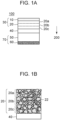
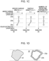
- FIG. 1 includes a schematic sectional view of a solid-state secondary battery according to the first embodiment ( Fig. 1A ), a partial enlarged view including an anode active material layer ( Fig. 1B ), a layer-thickness-direction profile of a specific surface area of anode active material particles ( Fig. 1C ), and schematic views of an outline and a section of a particle ( Fig. 1D ).
- Fig. 1A is a schematic sectional view of the solid-state secondary battery 100 to which the anode active material layer 20 of this embodiment is applied.
- the solid-state secondary battery 100 includes the solid electrolyte layer 40 on an opposite-side surface of the anode active material layer 20 from the anode current collector layer 10 in contact with the anode active material layer 20.
- the solid-state secondary battery 100 includes a cathode 70 at an opposite side of the electrolyte layer 40 from the side in contact with the active material layer 20.
- the cathode 70 includes a cathode active material layer 50 on a surface of the solid electrolyte layer 40 opposite from the surface in contact with the anode active material layer 20.
- the cathode 70 includes a cathode current collector layer 60 on a surface of the cathode active material layer 50 opposite from the surface in contact with the solid electrolyte layer 40.
- the solid-state secondary battery 100 includes the cathode 70, the solid electrolyte layer 40, and an anode 30 in a stacking direction 200.
- the anode current collector layer 10, the anode active material layer 20, the solid electrolyte layer 40, and an anode active material particle 22 may be alternatively referred to as a current collector layer 10, an active material layer 20, an electrolyte layer 40, and an active material particle 22, respectively, for the sake of simplicity.
- the "solid-state secondary battery” is used to mean a secondary battery in which at least an electrolyte includes a non-aqueous solid electrolyte, and may be alternatively referred to as a "secondary battery” or an "all-solid-state battery".
- the anode active material layer 20 which is obtained by omitting the anode current collector layer 10 from the anode 30 in Fig. 1A
- the cathode active material layer 50 which is obtained by omitting the cathode current collector layer 60 from the cathode 70 in Fig. 1A
- a cathode 70 may be referred to as a cathode 70.
- the anode current collector layer 10 is a conductor that performs electron conduction between an external circuit not illustrated in the drawing and the active material layer.
- a freestanding film (foil) of a metal such as stainless (also referred to as SUS) or aluminum or a stacked form of the metal supported on a resin is used.
- a freestanding film (foil) of a metal such as silver or copper or a stacked form of the metal supported on a resin is used.
- the anode active material layer 20 includes anode active material layers 20a, 20b, and 20c as sublayers, as illustrated in Fig. 1B .
- the anode active material layers 20a, 20b, and 20c are distinguished from each other by a unit of stacking of the sublayers composed of deposited active material particles 22.
- the stacking direction 200 of the anode active material layers 20a, 20b, and 20c, which are the sublayers, is parallel to a layer thickness direction, and thus may be referred to as a layer thickness direction 200.
- anode active material layer 20 active material particles 22 containing an oxide-based solid electrolyte such as LiCoO 2 (lithium cobalt oxide: hereinafter also abbreviated as LCO) or CoLiO 4 P (cobalt lithium phosphate) are applicable. Materials applicable to each layer will be described later.
- an anode active material particle 22 according to this embodiment has a particle portion 22b and projecting portions 22p that radially project in a plurality of directions on an outer surface of the particle portion 22b. In Fig. 1C , the particle portion 22b and the projecting portions 22p are omitted.
- a specific surface area Srv (m -4 ) S (m 2 )/V (m 3 ) ⁇ ⁇ (m -3 ) of the sublayers included in the anode active material layer 20 is controlled.
- the specific surface area Srv is defined as a surface area per unit volume.
- an increment ⁇ Srv of the specific surface area Srv in the case of active material particles 22 having projecting portions 22p is proportional to the number n (dimensionless) of projecting portions 22p per one particle of the active material particles 22.
- an increment ⁇ Srv of the specific surface area Srv in the case of active material particles 22 having projecting portions 22p is proportional to the number density ⁇ v (m -3 ) of particles per unit volume.
- an increment ⁇ Srv(i) of the specific surface area Srv(i) of a sublayer 20i of the active material layer 20 due to the presence of the projecting portions 22p is proportional to the product of the number density ⁇ v (m -3 ) of particles per unit volume and the number n (dimensionless) of projecting portions per one particle of the active material particles 22.
- the specific surface area Srv(i) of a sublayer 20(i) of the active material layer 20 due to the presence of the projecting portions 22p changes with a positive correlation to the product of the number density ⁇ v (m -3 ) of particles per unit volume and the number (dimensionless) of projecting portions per one particle of the active material particles 22.
- the binding force between the anode active material layer 20 and the solid electrolyte layer 40 may be stronger than the binding force between layers of other structural elements in some cases in view of the affinity between materials and the correlation of structures. If the binding force between the anode active material layer 20 and the anode current collector layer 10 is stronger than the binding force between the anode active material layer 20 and the solid electrolyte layer 40, the solid electrolyte layer 40 described below may be replaced by the anode current collector layer 10.
- the solid-state secondary battery 100 of this embodiment will be described below as an embodiment including an anode active material layer 20 containing lithium cobalt oxide and a solid electrolyte layer 40 containing lithium borate (hereinafter also referred to as
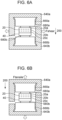
- Figs. 6A and 6B are schematic views illustrating the arrangement of a shear test in the layer direction and a tensile test in the layer thickness direction 200, respectively, for a specimen prepared by taking, from the solid-state secondary battery 100, a portion in which the solid electrolyte layer 40 and the anode active material layer 20 are bound together.
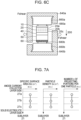
- Fig. 6C is a schematic view illustrating the arrangement of a shear test in the layer direction using the solid-state secondary battery 100 as a specimen.
- the arrangement illustrated in Fig. 6C can be used for specifying or separating layers (an interface) having a weak binding force.
- the "binding force” may also be referred to as an adhesive force, a fixing force, or an anchoring force.
- a breaking test machine not illustrated in the drawing is configured so as to be capable of fixing one of test holders 640a and 640b and applying a shear force Fshear or a tensile force Ftensile to the other.
- the test holders 640a and 640b illustrated in Figs. 6A to 6C and the breaking test machine not illustrated in the drawing have a structure in which the shear force Fshear or the tensile force Ftensile can be coaxially applied so that a rotational moment does not act on the specimen.
- the breaking test machine a publicly known apparatus capable of acquiring stress-strain characteristics and the precursor state of breaking can be used.
- the test holders 640a and 640b are configured to be capable of holding test jigs 660a and 660b bonded to the anode active material layer 10 and the solid electrolyte layer 40, which are objects to be peeled off, with adhesive layers 680a and 680b therebetween, respectively.
- the adhesive layers 680a and 680b may be formed of an adhesive that ensures an adhesive force for the material of a surface of the specimen to be adhered and the material of the test jigs 660a and 660b.
- An epoxy adhesive or a thermosetting adhesive is selected as the adhesive.
- the test jigs 660a and 660b used are each a disk-like metal member having a tapered flange portion.
- the test jigs 660a and 660b may be made of an aluminum material.
- test holders 640a and 640b have recesses in which the test jigs 660a and 660b can be inserted, respectively, with a predetermined gap therebetween and may be made of a metal such as brass or SUS.
- an active material layer 20c in contact with the solid electrolyte layer 40 has the minimum value of the number density ⁇ v of active material particles per unit volume, which is lower than those of the other active material layers 20b and 20a located on the side of the anode current collector layer 10.
- the active material layer 20c in contact with the solid electrolyte layer 40 has the minimum value of the specific surface area Srv, which is lower than those of the other sublayers.
- the anode active material layer 20 has a structure in which the binding force between the solid electrolyte layer 40 and the anode active material layer 20c is weaker than the binding forces between the other anode active material layers 20c and 20b and between the active material layers 20b and 20a.
- the interface between the solid electrolyte layer 40 and the anode active material layer 20c serves as a stress concentration surface on which a stress is concentrated such that peeling preferentially occurs due to a tensile stress parallel to the stacking direction 200 or a shear stress parallel to the layer direction compared with other regions.
- the region where the specific surface area is the minimum value extends to be parallel to a centroid surface of the sublayer 20c.
- the region where the specific surface area is the minimum value extends in a complementary direction or parallel to a plane orthogonal to the layer thickness direction.
- the anode active material layer 20 has, in the layer thickness direction 200, the first region where the specific surface area per one particle of the anode active material particles 22 is lower than that in another region in the layer thickness direction.
- a specimen taken from the solid-state secondary battery 100 of this embodiment and including the anode active material layer 20 and the solid electrolyte layer 40 was subjected to a shear fracture test with the arrangement of the test jigs illustrated in Fig. 6A .
- separated specimens 800A and 800B that were peeled off from each other were obtained as illustrated in Fig. 8A .
- the peeled, separated specimens 800A and 800B were cleanly peeled off from each other at a layer interface between (between layers of) the sublayer 20c of the anode active material layer 20 and the solid electrolyte layer 40.
- a state where a pair of specimens separated as a result of a fracture test mutually have a part of the structure of the counterpart may be referred to as separation at an unintended interface, irregular separation, or irregular peeling.
- the solid electrolyte layer 40 and the anode active material layer 20 of the solid-state secondary battery 100 of this embodiment were separated at the layer interface between the sublayer 20c and the solid electrolyte layer 40 without occurrence of irregular separation.
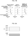
- Fig. 7A illustrates a layer-thickness-direction distribution of the specific surface area of an active material layer of a solid-state secondary battery including an anode active material layer 27 (not illustrated) according to a first reference mode.
- the anode active material layer 27 has sublayers 27a to 27c in this order from the anode current collector layer side toward the solid electrolyte layer side.
- the solid-state secondary battery according to this reference mode has a uniform layer-thickness-direction distribution of the specific surface area of the anode active material layer.
- the fragments of the solid-state secondary battery separated by such irregular-shaped breakage include mixtures of a plurality of structural elements 40-i and 27-i, such as the fragments 860B and 860C, resulting in a decrease in recyclability.
- the fragments of the solid-state secondary battery separated by such irregular-shaped breakage include fragments that are excessively small and separately require an analytical test in order to classify the fragments, such as the fragment 860D, resulting in a decrease in recyclability.
- the recyclability includes, for example, a reduction in the rate of recovery, an increase in the man-hour required for recovery, and an increase in the time required for recovery.
- Fig. 7B illustrates a layer-thickness-direction distribution of the specific surface area of an active material layer of a solid-state secondary battery including an anode active material layer 27 according to a second reference mode.
- the anode active material layer 27 (not illustrated) has sublayers 27a to 27c in this order from the anode current collector layer side toward the solid electrolyte layer side.
- the sublayer 20c on the solid electrolyte layer side has the maximum values in terms of the number of projecting portions and the specific surface area per one particle.
- the solid electrolyte layer and the sublayer 27c of the anode current collector layer are strongly bound to each other.
- the interface between the sublayers 27a and 27b is uniform. Accordingly, in a solid-state secondary battery including the anode active material layer according to this reference mode, when a tensile stress or a shear stress is applied to a test piece including the anode active material layer and the solid electrolyte layer as in the first reference mode, the stress distribution is indefinite. As a result, when a shear stress is applied to the test piece of the second reference mode to break the test piece, fissures propagate while repeating meandering and branching to form a plurality of fragments, resulting in a decrease in recyclability as in the test piece of the first reference mode.
- the solid-state secondary batteries including the anode active material layers according to the first reference mode and the second reference mode correspond to solid-state secondary batteries in the related art.
- the solid-state secondary battery 100 according to the first embodiment can be produced by a production method S2000 illustrated in the flowchart in Fig. 2A .
- the production method S2000 includes a step S200 of disposing an anode current collector layer, a step S210 of disposing an anode active material layer, a step S220 of disposing a solid electrolyte layer, a step S240 of disposing a cathode active material layer, and a step S260 of disposing a cathode current collector layer, and these steps are performed in this order.
- Fig. 2B is a flowchart illustrating a method S2100 for producing a solid-state secondary battery, the method being a modification of the production method S2000 of the first embodiment.
- This modification differs from the first embodiment in that the order of disposing the anode current collector layer 10, the anode active material layer 20, and the electrolyte layer 40 by stacking is reversed. That is, the order of steps of stacking an element and another adjacent element that constitute the solid-state secondary battery 100 can be exchanged or the steps can be simultaneously performed as long as the other element is not damaged.
- Fig. 2C is a flowchart illustrating a method S8200 for producing a secondary battery according to another modification of the production method S2000 of the first embodiment.
- the method S8200 for producing a secondary battery according to this modification differs from S2000 of the first embodiment and S2100 of a modification thereof in that the production of each of the anode 30 and the cathode 70 is performed in advance before stacking with the solid electrolyte layer 40.
- the anode active material layer 20 according to the first embodiment can be produced by a production method S3000 illustrated in the flowchart in Fig. 3A .
- the production method S3000 of this embodiment includes a step S200 of disposing an anode current collector layer, a step S300 of classifying anode active material particles, a step S320 of stacking an anode active material layer, and a step S220 of disposing a solid electrolyte layer, and these steps are performed in this order.
- the step S300 of classifying anode active material particles may be performed in parallel with the step S200 of disposing an anode current collector layer.
- Anode active material particles selected from the group of anode active material particles classified in the step S300 of classifying anode active material particles are used in each sublayer 20i stacked in the subsequent step of the step S320 of stacking an anode active material layer to adjust the specific surface area Svr(i) of the sublayer 20i.
- This step S320 can be performed by employing publicly known patterning methods and deposition methods such as an inkjet method, a sand painting method, and a mask CVD method.
- the distribution of the specific surface area Svr in the layer thickness direction is formed by using the step of stacking the sublayers 20i.
- post-processing of reducing the specific surface area in a predetermined region may be performed.
- Publicly known surface modification techniques including, for example, milling, FIB processing, blasting, and buffing are applicable to the post-processing.
- Fig. 3B is a flowchart illustrating a method S3100 for producing an anode active material layer 20, the method being a modification of the production method S3000 of the first embodiment. This modification differs from the first embodiment in that the order of disposing the anode current collector layer 10, the anode active material layer 20, and the electrolyte layer 40 by stacking is reversed.
- the steps S300 and S310 of the method S3000 for producing an anode active material layer 20 illustrated in Fig. 3A correspond to the step S210 of disposing an anode active material layer of the method S2000 for producing a solid-state secondary battery 100 illustrated in Fig. 2A .
- steps S300 and S310 of the method S3100 for producing an anode active material layer illustrated in Fig. 3B correspond to the step S210 of disposing an anode active material layer of the method S2100 for producing a solid-state secondary battery illustrated in Fig. 2A .
- a publicly known method is applicable to a method for producing a cathode.
- the method for producing an anode 30 of the first embodiment may be applied to the preparation of the cathode.
- the cathode may be formed of particles containing a cathode active material as in the anode 30, or formed as a film of a metal such as metallic Li or In-Li.
- Examples of the solid electrolyte applied to the solid electrolyte layer 40 will be described.
- Examples of the solid electrolyte include oxide-based solid electrolytes, sulfide-based solid electrolytes, and complex-hydride-based solid electrolytes.
- Examples of the oxide-based solid electrolytes include NASICON-type compounds such as Li 1.5 Al 0.5 Ge 1.5 (PO 4 ) 3 and Li 1.3 Al 0.3 Ti 1.7 (PO 4 ) 3 ; and garnet-type compounds such as Li 6.25 La 3 Zr 2 Al 0.25 O 12 .
- Examples of the oxide-based solid electrolytes further include perovskite-type compounds such as Li 0.33 Li 0.55 TiO 3 .
- examples of the oxide-based solid electrolytes include LISICON-type compounds such as Li 14 Zn(GeO 4 ) 4 and acid compounds such as Li 3 PO 4 , Li 4 SiO 4 , and Li 3 BO 3 .
- Specific examples of the sulfide-based solid electrolytes include Li 2 S-SiS 2 , LiI-Li 2 S-SiS 2 , LiI-Li 2 S-P 2 S 5 , LiI-Li 2 S-P 2 O 5 , LiI-Li 3 PO 4 -P 2 S 5 , and Li 2 S-P 2 S 5 .
- the solid electrolytes may be either crystalline or amorphous and may be glass-ceramics. Note that the description of, for example, Li 2 S-P 2 S 5 denotes a sulfide-based solid electrolyte produced by using raw materials containing Li 2 S and P 2 S 5 .
- examples of the cathode active material applied to the cathode active material layer 50 will be described.
- examples of the cathode material include metals, metal fibers, carbon materials, oxides, nitrides, silicon, silicon compounds, tin, tin compounds, and various alloy materials. Of these, in view of the capacity density, for example, metals, oxides, carbon materials, silicon, silicon compounds, tin, and tin compounds are preferred.
- the metals include metallic Li and In-Li
- examples of the oxides include Li 4 Ti 5 O 12 (LTO: lithium titanate).
- Examples of the carbon materials include various types of natural graphite (graphite), coke, graphitizing carbon, carbon fibers, spherical carbon, various types of artificial graphite, and amorphous carbon.
- Examples of the silicon compounds include silicon-containing alloys, silicon-containing inorganic compounds, silicon-containing organic compounds, and solid solutions.
- Examples of the tin compounds include SnO b (0 ⁇ b ⁇ 2), SnO 2 , SnSiO 3 , Ni 2 Sn 4 , and Mg 2 Sn.
- the above cathode material may contain a conductive auxiliary agent.
- Examples of the conductive auxiliary agent include graphite such as natural graphite and artificial graphite and carbon black such as acetylene black, ketjenblack, channel black, furnace black, lamp black, and thermal black.
- Examples of the conductive auxiliary agent include conductive fibers such as carbon fibers, carbon nanotubes, and metal fibers, fluorinated carbon, metal powders such as an aluminum powder, conductive whiskers such as zinc oxide, conductive metal oxides such as titanium oxide, and organic conductive materials such as phenylene dielectrics.
- conductive members containing a metal such as SUS, aluminum, or copper are used.
- the metal is used in the form of a metal foil, a freestanding film, or a thin-film supported on a base material.
- the anode active material layer 20 of this embodiment differs from the anode active material layer 20 of the first embodiment in that the specific surface area Srv is adjusted in each sublayer by changing the number n of projecting portions per one particle and that the anode active material layer 20 has four sublayers 20a to 20d.
- the anode active material layer 20 of this embodiment differs from the anode active material layer 20 of the first embodiment in that the specific surface area Svr gradually decreases over the sublayers 20b, 20c, and 20d.
- the binding force between the sublayer 20d of the anode active material layer 20 and the solid electrolyte layer 40 is weaker than the binding force between the other sublayers of the anode active material layer 20. Therefore, in the anode active material layer 20 according to this embodiment, the interface with the solid electrolyte layer 40 serves as a stress concentration surface for a shear force in the layer direction and a tensile force in the layer thickness direction as in the anode active material layer 20 of the first embodiment. In the solid-state secondary battery 100 including the anode active material layer 20 of this embodiment, recyclability of the raw material of the anode active material and the solid electrolyte material is ensured as in the first embodiment.
- a solid-state secondary battery 100 including an anode active material layer 20 according to a third embodiment will be described with reference to Fig. 4B .
- the anode active material layer 20 of this embodiment differs from the first embodiment in that the specific surface area Srv is adjusted in each sublayer by changing the number n of projecting portions per one particle and that the specific surface area Svr of a sublayer 20a located on the side of the anode current collector layer 10 has the minimum value.
- the binding force between the sublayer 20a of the anode active material layer 20 and the anode current collector layer 10 is weaker than the binding force between the other sublayers of the anode active material layer 20.
- the interface with the anode current collector layer 10 serves as a stress concentration surface for a shear force in the layer direction and a tensile force in the layer thickness direction.
- the interface with the anode current collector layer 10 serves as a stress concentration surface for a shear force in the layer direction and a tensile force in the layer thickness direction.
- the anode active material layer 20 of this embodiment differs from the anode active material layer 20 of the second embodiment in that, in a sublayer 20c, the specific surface area Srv has the minimum value, and in a sublayer 20d, the second lowest specific surface area Sv is exhibited.
- the binding force between the sublayers 20c and 20d of the anode active material layer 20 is weaker than the binding force between the other sublayers of the anode active material layer 20 and the binding force between the sublayer 20d and the solid electrolyte layer 40. Therefore, in the anode active material layer 20 according to this embodiment, the interface between the sublayers 20c and 20d serves as a stress concentration surface for a shear force in the layer direction and a tensile force in the layer thickness direction.
- the solid-state secondary battery 100 including the anode active material layer 20 of this embodiment differs from the first and second reference modes in that an anode active material layer including the sublayers 20a to 20c of the anode active material layer 20 is easily separated, and recyclability of the raw material of the anode active material is ensured.
- the fracture surface i.e., the cleaved surface formed by application of a shear force or a tensile force is a clear separation surface, it is expected that the rate of recovery of the solid electrolyte layer 40 is also improved compared with the first and second reference modes.
- the anode active material layer 20 of this embodiment differs from the anode active material layer 20 of the first embodiment in that the anode active material layer 20 of this embodiment has an intra-anode active material 24 coexisting with anode active material particles 22.
- the mixing ratio of the anode active material particles 22 and the intra-anode active material 24 in each of the sublayers 20a to 20c can be adjusted by the step S300 of classifying anode active material particles and the step S320 of stacking an anode active material layer in Fig. 3B .
- the intra-anode electrolyte 24 is provided in the anode active material layer 20 so as to have portions in contact with the anode active material particles 22.
- the sublayers 20a, 20b, and 20c of the anode active material layer may form a distribution in the layer thickness direction in terms of not only the mixing ratio (volume fraction) of the active material particles 22 and the intra-anode electrolyte 24 but also a conductive auxiliary agent not illustrated in the drawing, the void ratio (porosity), and the like.
- the anode active material particles 22 and the intra-anode electrolyte 24 may have different particle sizes and particle size distributions.
- the intra-anode electrolyte 24 and electrolyte particles that are contained in the solid electrolyte layer 40 and that are not illustrated in the drawing may have different particle sizes, particle size distributions, compositions, and the like.
- the anode active material layer 20 of this embodiment differs from the anode active material layer 20 of the first embodiment in that the anode active material layer 20 of this embodiment has an intra-anode active material 24 coexisting with anode active material particles 22 and that the intra-anode active material 24 and anode active material particles 22 are disposed in the layer in a predetermined arrangement pattern.
- the anode active material layer 20 of this embodiment differs from the anode active material layer 20 of the fifth embodiment in that the intra-anode active material 24 and anode active material particles 22 form a predetermined arrangement pattern and that the phases of patterns match each other in the sublayers 20a to 20c.
Landscapes
- Chemical & Material Sciences (AREA)
- General Chemical & Material Sciences (AREA)
- Chemical Kinetics & Catalysis (AREA)
- Electrochemistry (AREA)
- Engineering & Computer Science (AREA)
- Manufacturing & Machinery (AREA)
- Inorganic Chemistry (AREA)
- Materials Engineering (AREA)
- Crystallography & Structural Chemistry (AREA)
- Physics & Mathematics (AREA)
- Condensed Matter Physics & Semiconductors (AREA)
- General Physics & Mathematics (AREA)
- Composite Materials (AREA)
- Secondary Cells (AREA)
- Battery Electrode And Active Subsutance (AREA)
Abstract
Description
- The present invention relates to a solid-state secondary battery.
- In general, a secondary battery is composed of electrodes (an anode and a cathode) and an electrolyte and performs charging and discharging as a result of the movement of ions between the electrodes through the electrolyte. Such a secondary battery is used in various applications from small devices such as mobile phones to large devices such as electric vehicles. Therefore, further improvement in the performance of the secondary battery has been desired. To enhance charge-discharge characteristics of the secondary battery, in general, it is important to increase an interface between an active material in the electrode and the electrolyte. Herein, the "active material" refers to a substance involved in a reaction that generates electricity.
- To enhance charge-discharge characteristics, a technique of using an active material having fine projecting portions as an anode of a solid-state secondary battery is known as a specific measure.
Japanese Patent Laid-Open No. 2015-220080 - Meanwhile, when a secondary battery is disposed of, for example, at the end of the lifetime of the secondary battery or an electrical appliance on which the secondary battery is mounted, it is desirable to increase the rate of resource recovery and to easily perform separation of each material in view of environmental conservation.
Japanese Patent Laid-Open No. 2020-129157 Japanese Patent Laid-Open No. 2020-129157 -
Japanese Patent Laid-Open No. 2020-129157 -
- PTL 1:
Japanese Patent Laid-Open No. 2015-220080 - PTL 2:
Japanese Patent Laid-Open No. 2020-129157 - An all-solid-state battery (solid-state secondary battery) produced by using an active material layer containing active material particles having projecting portions and obtained by the method disclosed in
Japanese Patent Laid-Open No. 2015-220080 Fig. 5 . It was presumed that such an irregular separation was caused by an anchoring effect due to a plurality of projecting portions provided in order to ensure ion conductivity between adjacent particles and between adjacent layers. - As a result of studies conducted by the inventors of this application, it was anticipated that the phenomenon of this irregular separation is likely to propagate and significantly occurs in a plurality of directions in a region where a stress is concentrated between materials having close physical properties related to deformation such as elastic-plastic deformation. Since the irregular separation occurs at a solid-solid interface more significantly than at a solid-liquid interface in terms of structure, it is desirable to provide a solid-state secondary battery in which the problem of the irregular separation is unlikely to occur.
- It is also desirable to provide a solid-state secondary battery having enhanced separability at an interface between an active material layer and an electrolyte layer containing materials such as Li and Co having a high resource value and desired to have a high rate of recovery, at which the irregular separation is more likely to occur than at an interface between an active material layer and a current collector layer for which a relatively soft material can be selected.
- An object of this application is to provide a solid-state secondary battery in which detachability between an active material layer and a current collector layer and between an active material layer and a current collector layer is ensured and which includes an active material layer whose recyclability is ensured.
- A solid-state secondary battery according to an embodiment of the present invention includes an active material layer in which a plurality of active material particles are deposited in a layer thickness direction, the active material particles having a particle portion and a plurality of projecting portions that project from the particle portion in a plurality of directions; an electrolyte layer that performs transfer of active material ions with the active material particles; and a current collector layer that performs transfer of electrons with the active material particles, in which the active material layer has, in the layer thickness direction, a first region where a specific surface area of the active material particles is lower than that in another region in the layer thickness direction.
-
- [
Fig. 1A] Fig. 1A is a schematic sectional view of a solid-state secondary battery according to a first embodiment. - [
Fig. 1B] Fig. 1B is a partial enlarged view including an anode active material layer of the solid-state secondary battery according to the first embodiment. - [
Fig. 1C] Fig. 1C illustrates a layer-thickness-direction distribution of a specific surface area of anode active material particles of the solid-state secondary battery according to the first embodiment. - [
Fig. 1D] Fig. 1D includes schematic views of an outline and a section of the solid-state secondary battery according to the first embodiment. - [
Fig. 2A] Fig. 2A is a flowchart illustrating a method for producing a solid-state secondary battery according to the first embodiment. - [
Fig. 2B] Fig. 2B is a flowchart relating to a method for producing a solid-state secondary battery according to a modification. - [
Fig. 2C] Fig. 2C is a flowchart relating to a method for producing a solid-state secondary battery according to a modification. - [
Fig. 3A] Fig. 3A is a flowchart illustrating a method for producing an anode active material layer according to the first embodiment. - [
Fig. 3B] Fig. 3B is a flowchart illustrating a method for producing an anode active material layer according to a modification. - [
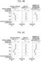
Fig. 4A] Fig. 4A is a layer-thickness-direction profile of a specific surface area of an anode active material layer according to a second embodiment. - [
Fig. 4B] Fig. 4B is a layer-thickness-direction profile of a specific surface area of an anode active material layer according to a third embodiment. - [
Fig. 4C] Fig. 4C is a layer-thickness-direction profile of a specific surface area of an anode active material layer according to a fourth embodiment. - [
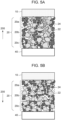
Fig. 5A] Fig. 5A is a partial enlarged view including an anode active material layer according to a fifth embodiment. - [
Fig. 5B] Fig. 5B is a partial enlarged view including an anode active material layer according to a sixth embodiment. - [
Fig. 6A] Fig. 6A is a view illustrating a holding form of a specimen of a shear test. - [
Fig. 6B] Fig. 6B is a view illustrating a holding form of a specimen of a uniaxial tensile test. - [
Fig. 6C] Fig. 6C is a view illustrating a holding form of a specimen of a shear test. - [
Fig. 7A] Fig. 7A is a layer-thickness-direction profile of a specific surface area of anode active material particles according to a first reference mode. - [
Fig. 7B] Fig. 7B is a layer-thickness-direction profile of a specific surface area of anode active material particles according to a second reference mode. - [
Fig. 8A] Fig. 8A is a view illustrating a specimen after a shear stress test of a solid-state secondary battery according to the first embodiment. - [
Fig. 8B] Fig. 8B is a view illustrating a specimen after a shear stress test of a solid-state secondary battery according to the first reference mode. - Hereinafter, preferred embodiments of the present invention will be described in detail with reference to the drawings. The dimensions, materials, shapes, relative positions, and the like of components described in the embodiments are not intended to limit the scope of the present invention.
- A solid-state
secondary battery 100 including an anodecurrent collector layer 10, an anodeactive material layer 20, and asolid electrolyte layer 40 according to a first embodiment will be described with reference toFigs. 1A to 1D. Fig. 1 includes a schematic sectional view of a solid-state secondary battery according to the first embodiment (Fig. 1A ), a partial enlarged view including an anode active material layer (Fig. 1B ), a layer-thickness-direction profile of a specific surface area of anode active material particles (Fig. 1C ), and schematic views of an outline and a section of a particle (Fig. 1D ). -
Fig. 1A is a schematic sectional view of the solid-statesecondary battery 100 to which the anodeactive material layer 20 of this embodiment is applied. The solid-statesecondary battery 100 includes thesolid electrolyte layer 40 on an opposite-side surface of the anodeactive material layer 20 from the anodecurrent collector layer 10 in contact with the anodeactive material layer 20. The solid-statesecondary battery 100 includes acathode 70 at an opposite side of theelectrolyte layer 40 from the side in contact with theactive material layer 20. Thecathode 70 includes a cathodeactive material layer 50 on a surface of thesolid electrolyte layer 40 opposite from the surface in contact with the anodeactive material layer 20. Thecathode 70 includes a cathodecurrent collector layer 60 on a surface of the cathodeactive material layer 50 opposite from the surface in contact with thesolid electrolyte layer 40. In other words, the solid-statesecondary battery 100 includes thecathode 70, thesolid electrolyte layer 40, and ananode 30 in a stackingdirection 200. - Hereinafter, in the specification of this application, the anode
current collector layer 10, the anodeactive material layer 20, thesolid electrolyte layer 40, and an anodeactive material particle 22 may be alternatively referred to as acurrent collector layer 10, anactive material layer 20, anelectrolyte layer 40, and anactive material particle 22, respectively, for the sake of simplicity. The "solid-state secondary battery" is used to mean a secondary battery in which at least an electrolyte includes a non-aqueous solid electrolyte, and may be alternatively referred to as a "secondary battery" or an "all-solid-state battery". - In the specification of this application, since electrode structures in which transfer of active material ions is performed with the
solid electrolyte layer 40 are referred to as an anode and a cathode, the anodeactive material layer 20, which is obtained by omitting the anodecurrent collector layer 10 from theanode 30 inFig. 1A , may be referred to as ananode 30. Similarly, the cathodeactive material layer 50, which is obtained by omitting the cathodecurrent collector layer 60 from thecathode 70 inFig. 1A , may be referred to as acathode 70. - The anode
current collector layer 10 is a conductor that performs electron conduction between an external circuit not illustrated in the drawing and the active material layer. As the anodecurrent collector layer 10, a freestanding film (foil) of a metal such as stainless (also referred to as SUS) or aluminum or a stacked form of the metal supported on a resin is used. As the cathodecurrent collector layer 60, a freestanding film (foil) of a metal such as silver or copper or a stacked form of the metal supported on a resin is used. - The anode
active material layer 20 includes anodeactive material layers Fig. 1B . The anodeactive material layers active material particles 22. The stackingdirection 200 of the anodeactive material layers layer thickness direction 200. As the anodeactive material layer 20,active material particles 22 containing an oxide-based solid electrolyte such as LiCoO2 (lithium cobalt oxide: hereinafter also abbreviated as LCO) or CoLiO4P (cobalt lithium phosphate) are applicable. Materials applicable to each layer will be described later. As illustrated inFig. 1D , an anodeactive material particle 22 according to this embodiment has aparticle portion 22b and projectingportions 22p that radially project in a plurality of directions on an outer surface of theparticle portion 22b. InFig. 1C , theparticle portion 22b and the projectingportions 22p are omitted. - A specific surface area Srv (m-4) = S (m2)/V (m3) × σ (m-3) of the sublayers included in the anode
active material layer 20 is controlled. By stacking thesublayers direction 200. In the specification of this application, the specific surface area Srv is defined as a surface area per unit volume. The specific surface area of asublayer 20i corresponds to the product of an average specific surface area per one particle Srp (m-1) = S (m2)/V (m3), a number density σv (m-3) of particles per unit volume, and a volume V of one layer. - When the
active material layer 20 does not have a significant distribution in the layer thickness direction in terms of the number density σv of particles per unit volume, an increment ΔSrv of the specific surface area Srv in the case ofactive material particles 22 having projectingportions 22p is proportional to the number n (dimensionless) of projectingportions 22p per one particle of theactive material particles 22. Similarly, when theactive material layer 20 does not have a significant distribution in the layer thickness direction in terms of the number of projectingportions 22p per one particle, an increment ΔSrv of the specific surface area Srv in the case ofactive material particles 22 having projectingportions 22p is proportional to the number density σv (m-3) of particles per unit volume. That is, an increment ΔSrv(i) of the specific surface area Srv(i) of asublayer 20i of theactive material layer 20 due to the presence of the projectingportions 22p is proportional to the product of the number density σv (m-3) of particles per unit volume and the number n (dimensionless) of projecting portions per one particle of theactive material particles 22. Thus, in other words, the specific surface area Srv(i) of a sublayer 20(i) of theactive material layer 20 due to the presence of the projectingportions 22p changes with a positive correlation to the product of the number density σv (m-3) of particles per unit volume and the number (dimensionless) of projecting portions per one particle of theactive material particles 22. - In the layers constituting the solid-state
secondary battery 100, the binding force between the anodeactive material layer 20 and thesolid electrolyte layer 40 may be stronger than the binding force between layers of other structural elements in some cases in view of the affinity between materials and the correlation of structures. If the binding force between the anodeactive material layer 20 and the anodecurrent collector layer 10 is stronger than the binding force between the anodeactive material layer 20 and thesolid electrolyte layer 40, thesolid electrolyte layer 40 described below may be replaced by the anodecurrent collector layer 10. The solid-statesecondary battery 100 of this embodiment will be described below as an embodiment including an anodeactive material layer 20 containing lithium cobalt oxide and asolid electrolyte layer 40 containing lithium borate (hereinafter also referred to as - Here, holding forms of a specimen when a separation test is performed using a solid-state
secondary battery 100 including the anodeactive material layer 20 of this embodiment will be described with reference toFigs. 6A to 6C . -
Figs. 6A and 6B are schematic views illustrating the arrangement of a shear test in the layer direction and a tensile test in thelayer thickness direction 200, respectively, for a specimen prepared by taking, from the solid-statesecondary battery 100, a portion in which thesolid electrolyte layer 40 and the anodeactive material layer 20 are bound together.Fig. 6C is a schematic view illustrating the arrangement of a shear test in the layer direction using the solid-statesecondary battery 100 as a specimen. The arrangement illustrated inFig. 6C can be used for specifying or separating layers (an interface) having a weak binding force. In the specification of this application, the "binding force" may also be referred to as an adhesive force, a fixing force, or an anchoring force. - A breaking test machine not illustrated in the drawing is configured so as to be capable of fixing one of
test holders test holders Figs. 6A to 6C and the breaking test machine not illustrated in the drawing have a structure in which the shear force Fshear or the tensile force Ftensile can be coaxially applied so that a rotational moment does not act on the specimen. As the breaking test machine, a publicly known apparatus capable of acquiring stress-strain characteristics and the precursor state of breaking can be used. - The
test holders test jigs active material layer 10 and thesolid electrolyte layer 40, which are objects to be peeled off, withadhesive layers adhesive layers test jigs - The
test holders test jigs - In the anode
active material layer 20 according to the first embodiment, as illustrated inFig. 1C , anactive material layer 20c in contact with thesolid electrolyte layer 40 has the minimum value of the number density σv of active material particles per unit volume, which is lower than those of the other active material layers 20b and 20a located on the side of the anodecurrent collector layer 10. As a result, theactive material layer 20c in contact with thesolid electrolyte layer 40 has the minimum value of the specific surface area Srv, which is lower than those of the other sublayers. Consequently, the anodeactive material layer 20 has a structure in which the binding force between thesolid electrolyte layer 40 and the anodeactive material layer 20c is weaker than the binding forces between the other anode active material layers 20c and 20b and between the active material layers 20b and 20a. As a result, the interface between thesolid electrolyte layer 40 and the anodeactive material layer 20c serves as a stress concentration surface on which a stress is concentrated such that peeling preferentially occurs due to a tensile stress parallel to the stackingdirection 200 or a shear stress parallel to the layer direction compared with other regions. - In the
active material layer 20, the region where the specific surface area is the minimum value extends to be parallel to a centroid surface of thesublayer 20c. In other words, in theactive material layer 20, the region where the specific surface area is the minimum value extends in a complementary direction or parallel to a plane orthogonal to the layer thickness direction. In other words, when a region of theactive material layer 20 where the specific surface area is the minimum value is defined as a first region, the anodeactive material layer 20 has, in thelayer thickness direction 200, the first region where the specific surface area per one particle of the anodeactive material particles 22 is lower than that in another region in the layer thickness direction. - A specimen taken from the solid-state
secondary battery 100 of this embodiment and including the anodeactive material layer 20 and thesolid electrolyte layer 40 was subjected to a shear fracture test with the arrangement of the test jigs illustrated inFig. 6A . As a result, separatedspecimens Fig. 8A . The peeled, separatedspecimens sublayer 20c of the anodeactive material layer 20 and thesolid electrolyte layer 40. In the specification of this application, a state where a pair of specimens separated as a result of a fracture test mutually have a part of the structure of the counterpart may be referred to as separation at an unintended interface, irregular separation, or irregular peeling. Thesolid electrolyte layer 40 and the anodeactive material layer 20 of the solid-statesecondary battery 100 of this embodiment were separated at the layer interface between the sublayer 20c and thesolid electrolyte layer 40 without occurrence of irregular separation. - On the other hand,
Fig. 7A illustrates a layer-thickness-direction distribution of the specific surface area of an active material layer of a solid-state secondary battery including an anode active material layer 27 (not illustrated) according to a first reference mode. The anode active material layer 27 hassublayers 27a to 27c in this order from the anode current collector layer side toward the solid electrolyte layer side. The solid-state secondary battery according to this reference mode has a uniform layer-thickness-direction distribution of the specific surface area of the anode active material layer. Accordingly, in the solid-state secondary battery including the anode active material layer according to this reference mode, when a tensile stress or a shear stress is applied to a test piece including the anode active material layer and the solid electrolyte layer, a region where the stress is concentrated is not aligned in a specific height region, and the stress distribution is indefinite. As a result, when a shear stress is applied to the test piece of the first reference mode to break the test piece, fissures (cracks) propagate while repeating meandering and branching to form a plurality offragments 860A to 860D as illustrated inFig. 8B . The fragments of the solid-state secondary battery separated by such irregular-shaped breakage include mixtures of a plurality of structural elements 40-i and 27-i, such as thefragments fragment 860D, resulting in a decrease in recyclability. The recyclability includes, for example, a reduction in the rate of recovery, an increase in the man-hour required for recovery, and an increase in the time required for recovery. - Furthermore,
Fig. 7B illustrates a layer-thickness-direction distribution of the specific surface area of an active material layer of a solid-state secondary battery including an anode active material layer 27 according to a second reference mode. The anode active material layer 27 (not illustrated) hassublayers 27a to 27c in this order from the anode current collector layer side toward the solid electrolyte layer side. - Since the distribution of the specific surface area in the
layer thickness direction 200 is uniform, when a tensile stress or a shear stress is applied to a test piece including the anode active material layer and the solid electrolyte layer, a region where the stress is concentrated is not concentrated in a specific region, and the stress distribution is indefinite. In the solid-state secondary battery according to this reference mode, thesublayer 20c on the solid electrolyte layer side has the maximum values in terms of the number of projecting portions and the specific surface area per one particle. - As a result, the solid electrolyte layer and the sublayer 27c of the anode current collector layer are strongly bound to each other.
- On the other hand, the interface between the
sublayers - Next, a process for producing a solid-state
secondary battery 100 of this embodiment will be described with reference to a flowchart inFig. 2A . The solid-statesecondary battery 100 according to the first embodiment can be produced by a production method S2000 illustrated in the flowchart inFig. 2A . The production method S2000 includes a step S200 of disposing an anode current collector layer, a step S210 of disposing an anode active material layer, a step S220 of disposing a solid electrolyte layer, a step S240 of disposing a cathode active material layer, and a step S260 of disposing a cathode current collector layer, and these steps are performed in this order. -
Fig. 2B is a flowchart illustrating a method S2100 for producing a solid-state secondary battery, the method being a modification of the production method S2000 of the first embodiment. This modification differs from the first embodiment in that the order of disposing the anodecurrent collector layer 10, the anodeactive material layer 20, and theelectrolyte layer 40 by stacking is reversed. That is, the order of steps of stacking an element and another adjacent element that constitute the solid-statesecondary battery 100 can be exchanged or the steps can be simultaneously performed as long as the other element is not damaged. -
Fig. 2C is a flowchart illustrating a method S8200 for producing a secondary battery according to another modification of the production method S2000 of the first embodiment. The method S8200 for producing a secondary battery according to this modification differs from S2000 of the first embodiment and S2100 of a modification thereof in that the production of each of theanode 30 and thecathode 70 is performed in advance before stacking with thesolid electrolyte layer 40. - Next, the step S210 of disposing an anode
active material layer 20 of this embodiment will be described with reference to flowcharts ofFigs. 3A and3B . The anodeactive material layer 20 according to the first embodiment can be produced by a production method S3000 illustrated in the flowchart inFig. 3A . The production method S3000 of this embodiment includes a step S200 of disposing an anode current collector layer, a step S300 of classifying anode active material particles, a step S320 of stacking an anode active material layer, and a step S220 of disposing a solid electrolyte layer, and these steps are performed in this order. - The step S300 of classifying anode active material particles includes a step of screening an average particle size, the number of projecting portions per one particle, a variation in the shape, and the like of anode
active material layers 20i (i = a, b, c -) . The step S300 of classifying anode active material particles may be performed in parallel with the step S200 of disposing an anode current collector layer. - Anode active material particles selected from the group of anode active material particles classified in the step S300 of classifying anode active material particles are used in each
sublayer 20i stacked in the subsequent step of the step S320 of stacking an anode active material layer to adjust the specific surface area Svr(i) of thesublayer 20i. This step S320 can be performed by employing publicly known patterning methods and deposition methods such as an inkjet method, a sand painting method, and a mask CVD method. - In the anode
active material layer 20 of this embodiment, the distribution of the specific surface area Svr in the layer thickness direction is formed by using the step of stacking thesublayers 20i. Alternatively, after the anodeactive material layer 20 is disposed, post-processing of reducing the specific surface area in a predetermined region may be performed. Publicly known surface modification techniques including, for example, milling, FIB processing, blasting, and buffing are applicable to the post-processing. -
Fig. 3B is a flowchart illustrating a method S3100 for producing an anodeactive material layer 20, the method being a modification of the production method S3000 of the first embodiment. This modification differs from the first embodiment in that the order of disposing the anodecurrent collector layer 10, the anodeactive material layer 20, and theelectrolyte layer 40 by stacking is reversed. The steps S300 and S310 of the method S3000 for producing an anodeactive material layer 20 illustrated inFig. 3A correspond to the step S210 of disposing an anode active material layer of the method S2000 for producing a solid-statesecondary battery 100 illustrated inFig. 2A . Similarly, the steps S300 and S310 of the method S3100 for producing an anode active material layer illustrated inFig. 3B correspond to the step S210 of disposing an anode active material layer of the method S2100 for producing a solid-state secondary battery illustrated inFig. 2A . - A publicly known method is applicable to a method for producing a cathode. As in a modification of a fourth embodiment of this application, the method for producing an
anode 30 of the first embodiment may be applied to the preparation of the cathode. The cathode may be formed of particles containing a cathode active material as in theanode 30, or formed as a film of a metal such as metallic Li or In-Li. - Next, examples of the solid electrolyte applied to the
solid electrolyte layer 40 will be described. Examples of the solid electrolyte include oxide-based solid electrolytes, sulfide-based solid electrolytes, and complex-hydride-based solid electrolytes. Examples of the oxide-based solid electrolytes include NASICON-type compounds such as Li1.5Al0.5Ge1.5(PO4)3 and Li1.3Al0.3Ti1.7(PO4)3; and garnet-type compounds such as Li6.25La3Zr2Al0.25O12. Examples of the oxide-based solid electrolytes further include perovskite-type compounds such as Li0.33Li0.55TiO3. In addition, examples of the oxide-based solid electrolytes include LISICON-type compounds such as Li14Zn(GeO4)4 and acid compounds such as Li3PO4, Li4SiO4, and Li3BO3. Specific examples of the sulfide-based solid electrolytes include Li2S-SiS2, LiI-Li2S-SiS2, LiI-Li2S-P2S5, LiI-Li2S-P2O5, LiI-Li3PO4-P2S5, and Li2S-P2S5. The solid electrolytes may be either crystalline or amorphous and may be glass-ceramics. Note that the description of, for example, Li2S-P2S5 denotes a sulfide-based solid electrolyte produced by using raw materials containing Li2S and P2S5. - Next, examples of the cathode active material applied to the cathode
active material layer 50 will be described. Examples of the cathode material include metals, metal fibers, carbon materials, oxides, nitrides, silicon, silicon compounds, tin, tin compounds, and various alloy materials. Of these, in view of the capacity density, for example, metals, oxides, carbon materials, silicon, silicon compounds, tin, and tin compounds are preferred. Examples of the metals include metallic Li and In-Li, and examples of the oxides include Li4Ti5O12 (LTO: lithium titanate). Examples of the carbon materials include various types of natural graphite (graphite), coke, graphitizing carbon, carbon fibers, spherical carbon, various types of artificial graphite, and amorphous carbon. Examples of the silicon compounds include silicon-containing alloys, silicon-containing inorganic compounds, silicon-containing organic compounds, and solid solutions. Examples of the tin compounds include SnOb (0 < b < 2), SnO2, SnSiO3, Ni2Sn4, and Mg2Sn. The above cathode material may contain a conductive auxiliary agent. Examples of the conductive auxiliary agent include graphite such as natural graphite and artificial graphite and carbon black such as acetylene black, ketjenblack, channel black, furnace black, lamp black, and thermal black. Examples of the conductive auxiliary agent include conductive fibers such as carbon fibers, carbon nanotubes, and metal fibers, fluorinated carbon, metal powders such as an aluminum powder, conductive whiskers such as zinc oxide, conductive metal oxides such as titanium oxide, and organic conductive materials such as phenylene dielectrics. - As the current collectors applied to the current collector layers 10 and 60, conductive members containing a metal such as SUS, aluminum, or copper are used. The metal is used in the form of a metal foil, a freestanding film, or a thin-film supported on a base material.
- Next, a solid-state
secondary battery 100 including an anodeactive material layer 20 according to a second embodiment will be described with reference toFig. 4A . The anodeactive material layer 20 of this embodiment differs from the anodeactive material layer 20 of the first embodiment in that the specific surface area Srv is adjusted in each sublayer by changing the number n of projecting portions per one particle and that the anodeactive material layer 20 has foursublayers 20a to 20d. The anodeactive material layer 20 of this embodiment differs from the anodeactive material layer 20 of the first embodiment in that the specific surface area Svr gradually decreases over thesublayers secondary battery 100 including the anodeactive material layer 20 according to this embodiment, the binding force between thesublayer 20d of the anodeactive material layer 20 and thesolid electrolyte layer 40 is weaker than the binding force between the other sublayers of the anodeactive material layer 20. Therefore, in the anodeactive material layer 20 according to this embodiment, the interface with thesolid electrolyte layer 40 serves as a stress concentration surface for a shear force in the layer direction and a tensile force in the layer thickness direction as in the anodeactive material layer 20 of the first embodiment. In the solid-statesecondary battery 100 including the anodeactive material layer 20 of this embodiment, recyclability of the raw material of the anode active material and the solid electrolyte material is ensured as in the first embodiment. - Next, a solid-state
secondary battery 100 including an anodeactive material layer 20 according to a third embodiment will be described with reference toFig. 4B . The anodeactive material layer 20 of this embodiment differs from the first embodiment in that the specific surface area Srv is adjusted in each sublayer by changing the number n of projecting portions per one particle and that the specific surface area Svr of asublayer 20a located on the side of the anodecurrent collector layer 10 has the minimum value. In the solid-statesecondary battery 100 including the anodeactive material layer 20 according to this embodiment, the binding force between the sublayer 20a of the anodeactive material layer 20 and the anodecurrent collector layer 10 is weaker than the binding force between the other sublayers of the anodeactive material layer 20. Therefore, in the anodeactive material layer 20 according to this embodiment, the interface with the anodecurrent collector layer 10 serves as a stress concentration surface for a shear force in the layer direction and a tensile force in the layer thickness direction. In the solid-statesecondary battery 100 including the anodeactive material layer 20 of this embodiment, recyclability of the raw material of the anode active material and the anode current collector material is ensured. - Next, a solid-state
secondary battery 100 including an anodeactive material layer 20 according to a fourth embodiment will be described with reference toFig. 4A . The anodeactive material layer 20 of this embodiment differs from the anodeactive material layer 20 of the second embodiment in that, in asublayer 20c, the specific surface area Srv has the minimum value, and in asublayer 20d, the second lowest specific surface area Sv is exhibited. In the solid-statesecondary battery 100 including the anodeactive material layer 20 according to this embodiment, the binding force between the sublayers 20c and 20d of the anodeactive material layer 20 is weaker than the binding force between the other sublayers of the anodeactive material layer 20 and the binding force between thesublayer 20d and thesolid electrolyte layer 40. Therefore, in the anodeactive material layer 20 according to this embodiment, the interface between the sublayers 20c and 20d serves as a stress concentration surface for a shear force in the layer direction and a tensile force in the layer thickness direction. The solid-statesecondary battery 100 including the anodeactive material layer 20 of this embodiment differs from the first and second reference modes in that an anode active material layer including thesublayers 20a to 20c of the anodeactive material layer 20 is easily separated, and recyclability of the raw material of the anode active material is ensured. In the solid-statesecondary battery 100 including the anodeactive material layer 20 of this embodiment, since the fracture surface, i.e., the cleaved surface formed by application of a shear force or a tensile force is a clear separation surface, it is expected that the rate of recovery of thesolid electrolyte layer 40 is also improved compared with the first and second reference modes. - Next, a solid-state
secondary battery 100 including an anodeactive material layer 20 according to a fifth embodiment will be described with reference toFig. 5A . The anodeactive material layer 20 of this embodiment differs from the anodeactive material layer 20 of the first embodiment in that the anodeactive material layer 20 of this embodiment has an intra-anodeactive material 24 coexisting with anodeactive material particles 22. The mixing ratio of the anodeactive material particles 22 and the intra-anodeactive material 24 in each of thesublayers 20a to 20c can be adjusted by the step S300 of classifying anode active material particles and the step S320 of stacking an anode active material layer inFig. 3B . For the sake of increasing the ion conductivity between the anodeactive material layer 20 and thesolid electrolyte layer 40, theintra-anode electrolyte 24 is provided in the anodeactive material layer 20 so as to have portions in contact with the anodeactive material particles 22. Thesublayers active material particles 22 and theintra-anode electrolyte 24 but also a conductive auxiliary agent not illustrated in the drawing, the void ratio (porosity), and the like. - The anode
active material particles 22 and theintra-anode electrolyte 24 may have different particle sizes and particle size distributions. In addition, theintra-anode electrolyte 24 and electrolyte particles that are contained in thesolid electrolyte layer 40 and that are not illustrated in the drawing may have different particle sizes, particle size distributions, compositions, and the like. - Next, a solid-state
secondary battery 100 including an anodeactive material layer 20 according to a sixth embodiment will be described with reference toFig. 5B . The anodeactive material layer 20 of this embodiment differs from the anodeactive material layer 20 of the first embodiment in that the anodeactive material layer 20 of this embodiment has an intra-anodeactive material 24 coexisting with anodeactive material particles 22 and that the intra-anodeactive material 24 and anodeactive material particles 22 are disposed in the layer in a predetermined arrangement pattern. The anodeactive material layer 20 of this embodiment differs from the anodeactive material layer 20 of the fifth embodiment in that the intra-anodeactive material 24 and anodeactive material particles 22 form a predetermined arrangement pattern and that the phases of patterns match each other in thesublayers 20a to 20c. - The present invention is not limited to the above-described embodiments, and various changes and modifications may be made without departing from the spirit and scope of the present invention. Accordingly, in order to make the scope of the present invention public, the following claims are appended.
- This application claims the benefit of
Japanese Patent Application No. 2020-203467 filed December 8, 2020
Claims (8)
- A solid-state secondary battery comprising an active material layer in which a plurality of active material particles are deposited in a layer thickness direction, the active material particles having a particle portion and a plurality of projecting portions that project from the particle portion in a plurality of directions; an electrolyte layer that performs transfer of active material ions with the active material particles; and a current collector layer that performs transfer of electrons with the active material particles,
wherein the active material layer has, in the layer thickness direction, a first region where a specific surface area of the active material particles is lower than that in another region in the layer thickness direction. - The solid-state secondary battery according to Claim 1, wherein the first region extends in a layer direction of the active material layer.
- The solid-state secondary battery according to Claim 1 or 2, wherein the first region includes a region where at least one of a tensile stress in the layer thickness direction and a shear stress in a layer direction is concentrated compared with another region in the layer thickness direction.
- The solid-state secondary battery according to any one of Claims 1 to 3, wherein the first region includes a position at which the active material particles are in contact with the electrolyte layer or the current collector layer.
- The solid-state secondary battery according to any one of Claims 1 to 4, wherein the active material layer has, in the layer thickness direction, a first region where a specific surface area per one particle of the active material particles is
lower than that in another region in the layer thickness direction. - The solid-state secondary battery according to any one of Claims 1 to 5, wherein the active material particles contain at least one of lithium cobalt oxide and cobalt lithium phosphate.
- The solid-state secondary battery according to any one of Claims 1 to 6, wherein the electrolyte layer is a solid electrolyte layer.
- The solid-state secondary battery according to Claim 7, wherein the solid electrolyte contains an oxide-based solid electrolyte containing a metal oxide.
Applications Claiming Priority (2)
| Application Number | Priority Date | Filing Date | Title |
|---|---|---|---|
| JP2020203467A JP7752938B2 (en) | 2020-12-08 | 2020-12-08 | solid state secondary battery |
| PCT/JP2021/044396 WO2022124213A1 (en) | 2020-12-08 | 2021-12-03 | Solid-state secondary battery |
Publications (2)
| Publication Number | Publication Date |
|---|---|
| EP4243112A1 true EP4243112A1 (en) | 2023-09-13 |
| EP4243112A4 EP4243112A4 (en) | 2025-02-05 |
Family
ID=81973229
Family Applications (1)
| Application Number | Title | Priority Date | Filing Date |
|---|---|---|---|
| EP21903317.2A Withdrawn EP4243112A4 (en) | 2020-12-08 | 2021-12-03 | SOLID-STATE SECONDARY BATTERY |
Country Status (5)
| Country | Link |
|---|---|
| US (1) | US20230317943A1 (en) |
| EP (1) | EP4243112A4 (en) |
| JP (1) | JP7752938B2 (en) |
| CN (1) | CN116601783A (en) |
| WO (1) | WO2022124213A1 (en) |
Families Citing this family (1)
| Publication number | Priority date | Publication date | Assignee | Title |
|---|---|---|---|---|
| US12401047B2 (en) * | 2021-09-17 | 2025-08-26 | Samsung Electronics Co., Ltd. | Electrode structure for secondary battery, method of manufacturing the same, and secondary battery comprising the same |
Family Cites Families (17)
| Publication number | Priority date | Publication date | Assignee | Title |
|---|---|---|---|---|
| JP3719312B2 (en) * | 1997-07-07 | 2005-11-24 | 宇部興産株式会社 | Positive electrode sheet and non-aqueous electrolyte secondary battery using the same |
| JP2006210003A (en) * | 2005-01-25 | 2006-08-10 | Nissan Motor Co Ltd | Battery electrode |
| JP5333184B2 (en) * | 2009-03-16 | 2013-11-06 | トヨタ自動車株式会社 | All solid state secondary battery |
| KR101230684B1 (en) * | 2009-09-24 | 2013-02-07 | 다이니폰 스크린 세이조우 가부시키가이샤 | Battery manufacturing method and battery |
| JP5144703B2 (en) * | 2010-03-19 | 2013-02-13 | 大日本スクリーン製造株式会社 | Manufacturing method of all solid state battery |
| WO2012044132A2 (en) * | 2010-09-30 | 2012-04-05 | 주식회사 엘지화학 | Positive electrode for lithium secondary battery and lithium secondary battery including same |
| JP5413355B2 (en) * | 2010-11-08 | 2014-02-12 | トヨタ自動車株式会社 | All solid battery |
| JP2012134023A (en) * | 2010-12-22 | 2012-07-12 | Hitachi Vehicle Energy Ltd | Lithium ion secondary battery |
| JP5929183B2 (en) * | 2011-12-28 | 2016-06-01 | 株式会社豊田中央研究所 | Electrode, lithium secondary battery, and electrode manufacturing method |
| JP2015146249A (en) * | 2014-02-03 | 2015-08-13 | トヨタ自動車株式会社 | Nonaqueous electrolyte secondary battery |
| JP6228890B2 (en) | 2014-05-16 | 2017-11-08 | 新光電気工業株式会社 | Electrode body and method for producing electrode body |
| JP2016033876A (en) * | 2014-07-31 | 2016-03-10 | トヨタ自動車株式会社 | Recovery method of positive electrode active material component |
| CN110890525B (en) * | 2018-09-11 | 2023-08-11 | 艾可普罗 Bm 有限公司 | Positive electrode active material for lithium secondary battery and lithium secondary battery including same |
| JP7082938B2 (en) * | 2018-12-12 | 2022-06-09 | 三洋電機株式会社 | Secondary battery |
| JP6811265B2 (en) | 2019-02-07 | 2021-01-13 | ウィンボンド エレクトロニクス コーポレーション | Reference voltage generation circuit, power-on detection circuit and semiconductor device |
| JP2020129517A (en) * | 2019-02-12 | 2020-08-27 | トヨタ自動車株式会社 | Laminate |
| JP7301620B2 (en) | 2019-06-19 | 2023-07-03 | キヤノン株式会社 | liquid ejection head |
-
2020
- 2020-12-08 JP JP2020203467A patent/JP7752938B2/en active Active
-
2021
- 2021-12-03 EP EP21903317.2A patent/EP4243112A4/en not_active Withdrawn
- 2021-12-03 CN CN202180081689.3A patent/CN116601783A/en active Pending
- 2021-12-03 WO PCT/JP2021/044396 patent/WO2022124213A1/en not_active Ceased
-
2023
- 2023-06-05 US US18/329,447 patent/US20230317943A1/en active Pending
Also Published As
| Publication number | Publication date |
|---|---|
| JP7752938B2 (en) | 2025-10-14 |
| WO2022124213A1 (en) | 2022-06-16 |
| JP2022090892A (en) | 2022-06-20 |
| EP4243112A4 (en) | 2025-02-05 |
| CN116601783A (en) | 2023-08-15 |
| US20230317943A1 (en) | 2023-10-05 |
Similar Documents
| Publication | Publication Date | Title |
|---|---|---|
| JP6941808B2 (en) | All solid state battery | |
| CN104919627B (en) | All-solid-state battery and its manufacture method | |
| CN108695548B (en) | Laminated all-solid-state battery and method for manufacturing same | |
| EP3576208B1 (en) | All-solid-state battery and production method of the same | |
| CN110249467B (en) | All-solid-state battery and method for manufacturing same | |
| Liu et al. | In situ TEM electrochemistry of anode materials in lithium ion batteries | |
| CN103918110B (en) | Electrolyte-coated positive electrode active material particle, all-solid battery, and method for producing electrolyte-coated positive electrode active material particle | |
| CN112803078B (en) | Method for manufacturing all-solid-state battery and all-solid-state battery | |
| Cheng et al. | Electrically conductive ultrananocrystalline diamond-coated natural graphite-copper anode for new long life lithium-ion battery | |
| Yamauchi et al. | Performance of lithium-ion battery with tin-phosphate glass anode and its characteristics | |
| CN110416598B (en) | All-solid-state battery and method for manufacturing same | |
| EP2963704A1 (en) | Solid state lithium secondary battery and method for producing the same | |
| KR20160002988A (en) | Electrochemical cell with solid and liquid electrolytes | |
| EP2150998A1 (en) | A silicon anode for a rechargeable battery | |
| CN110235284A (en) | The manufacturing method of all-solid-state battery electrode and the manufacturing method of all-solid-state battery | |
| CN110165300B (en) | Method for manufacturing all-solid-state battery | |
| EP3972009A1 (en) | Electrode, battery, and method for manufacturing electrode | |
| EP3683878A1 (en) | All-solid battery and method of manufacturing the same | |
| US20220416251A1 (en) | Electrode layer and all-solid-state battery | |
| CN108432028B (en) | High current for the lithium ion battery with Metal Substrate cathode is handled | |
| US20230317943A1 (en) | Solid-state secondary battery | |
| EP2421076A1 (en) | Non-aqueous electrolyte secondary battery and process for production thereof | |
| Arbizzani et al. | Carbon paper as three-dimensional conducting substrate for tin anodes in lithium-ion batteries | |
| JP2024540188A (en) | Protected electrode structure for solid-state cells | |
| CN116364853B (en) | Negative electrode layer, manufacturing method of negative electrode layer and all-solid-state battery |
Legal Events
| Date | Code | Title | Description |
|---|---|---|---|
| STAA | Information on the status of an ep patent application or granted ep patent |
Free format text: STATUS: THE INTERNATIONAL PUBLICATION HAS BEEN MADE |
|
| PUAI | Public reference made under article 153(3) epc to a published international application that has entered the european phase |
Free format text: ORIGINAL CODE: 0009012 |
|
| STAA | Information on the status of an ep patent application or granted ep patent |
Free format text: STATUS: REQUEST FOR EXAMINATION WAS MADE |
|
| 17P | Request for examination filed |
Effective date: 20230605 |
|
| AK | Designated contracting states |
Kind code of ref document: A1 Designated state(s): AL AT BE BG CH CY CZ DE DK EE ES FI FR GB GR HR HU IE IS IT LI LT LU LV MC MK MT NL NO PL PT RO RS SE SI SK SM TR |
|
| DAV | Request for validation of the european patent (deleted) | ||
| DAX | Request for extension of the european patent (deleted) | ||
| A4 | Supplementary search report drawn up and despatched |
Effective date: 20250109 |
|
| RIC1 | Information provided on ipc code assigned before grant |
Ipc: H01M 4/136 20100101ALI20250102BHEP Ipc: H01M 4/36 20060101ALI20250102BHEP Ipc: H01M 4/131 20100101ALI20250102BHEP Ipc: H01M 10/54 20060101ALI20250102BHEP Ipc: H01M 10/058 20100101ALI20250102BHEP Ipc: H01M 10/0562 20100101ALI20250102BHEP Ipc: H01M 4/58 20100101ALI20250102BHEP Ipc: H01M 4/525 20100101ALI20250102BHEP Ipc: H01M 4/13 20100101AFI20250102BHEP |
|
| STAA | Information on the status of an ep patent application or granted ep patent |
Free format text: STATUS: THE APPLICATION IS DEEMED TO BE WITHDRAWN |
|
| 18D | Application deemed to be withdrawn |
Effective date: 20250729 |