EP4243033A1 - Simulated spent fuel storage tank for nuclear power station - Google Patents
Simulated spent fuel storage tank for nuclear power station Download PDFInfo
- Publication number
- EP4243033A1 EP4243033A1 EP20935478.6A EP20935478A EP4243033A1 EP 4243033 A1 EP4243033 A1 EP 4243033A1 EP 20935478 A EP20935478 A EP 20935478A EP 4243033 A1 EP4243033 A1 EP 4243033A1
- Authority
- EP
- European Patent Office
- Prior art keywords
- spent fuel
- storage tank
- simulated
- top cover
- nuclear power
- Prior art date
- Legal status (The legal status is an assumption and is not a legal conclusion. Google has not performed a legal analysis and makes no representation as to the accuracy of the status listed.)
- Granted
Links
Images





Classifications
-
- G—PHYSICS
- G21—NUCLEAR PHYSICS; NUCLEAR ENGINEERING
- G21C—NUCLEAR REACTORS
- G21C19/00—Arrangements for treating, for handling, or for facilitating the handling of, fuel or other materials which are used within the reactor, e.g. within its pressure vessel
- G21C19/02—Details of handling arrangements
- G21C19/06—Magazines for holding fuel elements or control elements
- G21C19/07—Storage racks; Storage pools
-
- G—PHYSICS
- G09—EDUCATION; CRYPTOGRAPHY; DISPLAY; ADVERTISING; SEALS
- G09B—EDUCATIONAL OR DEMONSTRATION APPLIANCES; APPLIANCES FOR TEACHING, OR COMMUNICATING WITH, THE BLIND, DEAF OR MUTE; MODELS; PLANETARIA; GLOBES; MAPS; DIAGRAMS
- G09B9/00—Simulators for teaching or training purposes
-
- G—PHYSICS
- G21—NUCLEAR PHYSICS; NUCLEAR ENGINEERING
- G21F—PROTECTION AGAINST X-RADIATION, GAMMA RADIATION, CORPUSCULAR RADIATION OR PARTICLE BOMBARDMENT; TREATING RADIOACTIVELY CONTAMINATED MATERIAL; DECONTAMINATION ARRANGEMENTS THEREFOR
- G21F5/00—Transportable or portable shielded containers
- G21F5/005—Containers for solid radioactive wastes, e.g. for ultimate disposal
- G21F5/008—Containers for fuel elements
- G21F5/012—Fuel element racks in the containers
-
- G—PHYSICS
- G21—NUCLEAR PHYSICS; NUCLEAR ENGINEERING
- G21F—PROTECTION AGAINST X-RADIATION, GAMMA RADIATION, CORPUSCULAR RADIATION OR PARTICLE BOMBARDMENT; TREATING RADIOACTIVELY CONTAMINATED MATERIAL; DECONTAMINATION ARRANGEMENTS THEREFOR
- G21F5/00—Transportable or portable shielded containers
- G21F5/06—Details of, or accessories to, the containers
-
- Y—GENERAL TAGGING OF NEW TECHNOLOGICAL DEVELOPMENTS; GENERAL TAGGING OF CROSS-SECTIONAL TECHNOLOGIES SPANNING OVER SEVERAL SECTIONS OF THE IPC; TECHNICAL SUBJECTS COVERED BY FORMER USPC CROSS-REFERENCE ART COLLECTIONS [XRACs] AND DIGESTS
- Y02—TECHNOLOGIES OR APPLICATIONS FOR MITIGATION OR ADAPTATION AGAINST CLIMATE CHANGE
- Y02E—REDUCTION OF GREENHOUSE GAS [GHG] EMISSIONS, RELATED TO ENERGY GENERATION, TRANSMISSION OR DISTRIBUTION
- Y02E30/00—Energy generation of nuclear origin
- Y02E30/30—Nuclear fission reactors
Definitions
- the present invention generally relates to nuclear power plants and, more particularly, relates to a simulated spent fuel storage tank for a nuclear power station.
- spent fuel dry storage technology has been widely used in the world.
- a typical technical feature of spent fuel dry storage is that the spent fuel assembly is enclosed in sealed helium filled spent fuel storage tank and the spent fuel storage tank is stored in a concrete module via a transfer container, and the passive natural ventilation cooling is carried out by using natural ventilation.
- thermal numerical simulation has the advantages of convenient modeling, fast calculation, good visualization effect and low cost.
- thermal numerical simulation has the advantages of convenient modeling, fast calculation, good visualization effect and low cost.
- the prior art needs to complete the welding of the spent fuel storage tanks, vacuum drying, module storage and the cutting and retrieval operations of spent fuel assemblies.
- it is necessary to identify the process operation to prove the rationality of the equipment design and the manufacturing reliability.
- the lack of spent fuel storage tanks for skills training has led to insufficient operational skills of operators. For example, in the case of storage operation, when the spent fuel storage tank is lifted vertically or pushed into the module horizontally, once the deviation of the horizontal and vertical face-to-face will occur, the storage tank will jam and collide easily, which will bring about the safety risk.
- One object of the present invention is to overcome the disadvantages of the prior art and provides a simulated spent fuel storage tank for nuclear power plant, which can meet the practical requirements of thermal performance and process operation qualification of spent fuel storage tank and skills training of operator.
- a simulated spent fuel storage tank for nuclear power station includes a simulated storage tank, simulated spent fuel assemblies received in the simulated storage tank, and an electric heater, wherein the simulated spent fuel assemblies are electrically connected to the electric heater (3) by cables.
- the simulated storage tank includes a bottom plate, a cylinder body arranged on the bottom plate, a simulated spent fuel grid in the cylinder body, and an inner top cover and an outer top cover independent from each other seated on a top of the cylinder body, wherein the inner top cover is provided with two bolting grooves, and a siphon block and a inflatable block at two sides of the cylinder body are inserted in the two bolting grooves respectively.
- the bolting groove is provided with a layer of independent cover plate, and the cover plate is welded to the inner top cover.
- an inner top cover support for supporting the inner top cover is provided on a top of the inner sidewall of the cylinder body, and a support screw is arranged on a top of the inner top cover support, and the support screw penetrates a bolting groove defined in the inner top cover to fix the inner top cover via a bolt.
- the inner top cover is provided with a bolting groove, a clamp groove located above the bolting groove, and a bolting groove cover plate, the bolting groove is provided with a through hole, and the support screw on the top of the inner top cover support passes through the through hole and couples the inner top cover to the cylinder body via bolt thread connection, with the clamp groove sleeving on the inner top cover support for fixing the inner top cover support.
- the outer top cover is formed with a first body, a first cable hole extending through the first body and a first cable penetrator disposed in the first cable hole, wherein the first cable penetrator seals the first cable hole via welding or via thread connection.
- the first cable penetrator is a two-step cylinder with a cable penetrating passage in a middle thereof, for connecting a cable running through the inner top cover to the electric heater through the outer top cover.
- the inner top cover includes a second body, a siphon block through hole and an inflatable block through hole defined in the second body, and a second cable hole and a second cable penetrator corresponding to the first cable hole and the first cable penetrator, and the second cable hole is provided with a cover plate.
- the siphon block includes a siphon connection block, a drain pipe, and a quick connector for connecting the siphon connection block and the drain pipe.
- the simulated spent fuel grid includes a plurality of storage chambers, with each storage chamber containing a set of simulated spent fuel assemblies, the simulated spent fuel assembly includes an upper tube seat, a lower tube seat, and a square tube between the upper tube seat and the lower tube seat, the square tube is provided with a cross bracket to divide the square tube into four storage units, and each storage unit stores an electric heating rod.
- the electric heating rod includes a housing, a heating wire fixing rod seated in the housing, and an electric heating wire set around the heating wire fixing rod, wherein a filling insulation material is arranged between the housing and the electric heating wire, and the cable connecting the electric heating wire is formed with a protective sleeve.
- the upper tube seat is provided with a base seat, a cable wire hole corresponding to the cable, and a protective platform arranged on an outer edge of the base seat.
- the lower tube seat includes a base seat, a support leg for supporting the base seat, and a holding slot for sleeving and fixing the cross bracket.
- the simulated spent fuel storage tank for the nuclear power plant of the invention can be used for thermal identification and operation training tests, and is based on the actual loading, storage quantity and heat release of the spent fuel assembly, it can accurately simulate the layout state and thermal power of the spent fuel assembly, and realize the thermal performance appraisal of the spent fuel storage tank, the problem that the existing spent fuel storage system cannot be verified by numerical simulation is solved.
- the simulated spent fuel storage tank for the nuclear power plant can also simulate vacuum drying, automatic welding and cutting and retrieving operations under the real heating environment, and can also simulate the load of the real spent fuel assembly to carry out the transfer and storage operations of the storage tank, the utility model can improve the skill level of the operator and avoid the occurrence of human-related events.
- one embodiment of the present invention provides a simulated spent fuel storage tank for a nuclear power plant including a simulated storage tank 1, a simulated spent fuel assembly 2 contained in the simulated storage tank 1, and an electric heater 3, wherein the simulated spent fuel assembly 2 is electrically connected with the electric heater 3 via a cable to realize the electric heating function of the simulated spent fuel assembly 2.
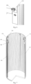
- the simulated storage tank 1 includes a bottom plate 17, a cylinder body 13 on the bottom plate 17, a simulated spent fuel grid 16 within the cylinder body 13, and an inner top cover 12 and an outer top cover 11 located at the top of the cylinder body 13 and independent from each other, wherein two penetration holes are arranged on the inner top cover 12, the siphon block 14 and the inflatable block 15 located on both sides of the cylinder body 13 are nested in two penetration holes respectively (as shown in Fig. 2 ) .
- the outer top cover 11 and the inner top cover 12 are mutually independent circular cover plates for simulating automatic welding and cutting process operation.
- the siphon block 14 and the inflatable block 15 are independent from each other and are positioned on both sides of the cylinder body 13 respectively and are fixedly connected by welding.
- An independent small cover plate is arranged on the penetration hole of the inner top cover 12, and each small cover plate is connected with the inner top cover 12 by welding.
- the siphon block 14 and the inflatable block 15 are provided with quick connectors inside for simulating the operation of filling and draining the spent fuel storage tank with gas, pumping and vacuum drying and filling with helium gas.
- the bottom plate 17 is provided with a water collecting tank.
- the drain pipe and the siphon block 14 are fixed by screw thread to drain the boron-containing water in the tank through a siphon effect.
- the simulated spent fuel grid 16 is located inside the cylinder body 13, the simulated spent fuel grid 16 and the bottom plate 17 can be fixedly connected by welding or fastening, and the simulated spent fuel grid 6 and the cylinder body 13 can be fixed by filling or supporting.
- the outer top cover 11 is provided with a first body 111, a first cable hole 113 extending through the first body 111, and a first cable penetrator 114 disposed in the first cable hole 113.
- the first penetrator 114 seals the first cable hole 113 through a welding or threaded connection.
- the weld groove 112 can adopt V-type groove with different structure forms to simulate the automatic welding operation of the storage tank cover plate and the cutting and retrieving operation of the cover plate.
- the first cable hole 113 may be provided with one or more, and in the embodiment shown in Fig. 3 , four first cable holes 113 are provided.
- the first cable penetrator 114 is a two-step cylinder defining a cable penetrates passage in a middle thereof, which is used for connecting the cable which penetrates from the inner top cover 12 to the electric heater 3 through the outer top cover 11.
- the inner top cover 12 includes a second body 121, a siphon block perforating hole and an inflatable block perforating hole 122 provided on the second body 121, and a second cable hole 124 and a second cable penetrator 125 arranged corresponding to the first cable hole 113 and the first cable penetrator 114, and the second cable hole 124 is provided with a cover plate 123.
- the siphon block and the inflatable block have two perforating holes 122, which are equidistant distributed at both ends through the center of the cover plate 123, and are used for sleeving the siphon block 14 and the inflatable block 15 respectively.
- the inner side wall 131 of the cylinder body 13 is provided with an inner top cover support 132 for supporting the inner top cover 12, and the top of the inner top cover support 132 is provided with a support screw 133, the support screw 133 penetrates the bolting groove 126 arranged on the inner top cover 12, to fix the inner top cover 12 via bolt connection.
- the inner top cover 12 is provided with a bolting groove 126, a clamp groove 128 above the bolting groove 126, and a bolting groove cover plate 127.
- the bolting groove 126 is provided with a perforated hole
- the top of the inner top cover support 132 is provided with a supporting screw 133, which passes through the perforated hole and fixes the inner top cover 12 to the cylinder 13 through a bolt thread connection.
- the clamp groove 128 is sleeved on the inner top cover support 132, to support and fix the inner top cover 12.
- each bolting groove 126 defines a perforated hole, for use in the full-load and no-load tests of the spent fuel assemblies shown in Figs. 3 and 4 .
- the support screw of the inner top cover is passed through the perforated hole, and a bolt is mounted on the upper part of the inner top cover 12, to fix the inner top cover 12 in the cylinder body 13, to ensure that the simulated spent fuel assembly 2 does not slip out in horizontal operation and protect the simulated spent fuel grid 16.
- the siphon block 14 includes a siphon connection block 141, a drain pipe 143, and a quick connector 142 connecting the siphon connection block 141 and the drain pipe 143.
- the difference between the inflatable block 15 and the siphon block 14 lies only in the absence of a drain pipe 143. In this manner, the device can be used for simulating the operation of inflatable drainage, vacuum drying and helium filling.
- the simulated spent fuel grid 16 includes several storage chambers, each storage chamber containing a group of simulated spent fuel assemblies 2.
- the simulated spent fuel grid 16 may consist of integral panels or single division plates welded together.
- the simulated spent fuel grid 16 includes totally storage chambers, each containing a group of simulated spent fuel assemblies 2.
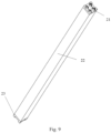
- the simulated spent fuel assembly 2 includes an upper tube seat 21, a lower tube seat 23, and a square tube 22 between the upper tube seat 21 and the lower tube seat 23, the upper tube seat 21, the square tube 22 and the lower tube seat 23 are fixedly connected by welding, and are generally rectangular bodies with square cross sections.
- the square tube 22 is provided with a cross bracket 25 and divided into four storage units, each of which stores an electric heating rod 24.
- a cross bracket 25 is nested at the outside of each electric heating rod 24 from the top, middle and bottom positions.
- the electric heating rod 24 preferably is made from stainless steel, with a cylindrical middle section and two spherical crowns at two ends.
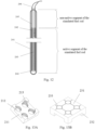
- the electric heating rod 24 includes a housing 241, a heating wire fixing rod 244 seated in the housing 241, and an electric heating wire 242 arranged around the heating wire fixing rod 244, wherein a filling insulation material 243(such as magnesium oxide) is arranged between the housing 241 and the electric heating wire 242, and the cable 246 connecting the electric heating wire 242 is provided with a protective sleeve 245.
- the electric heating wire 242 is a U-shaped loop coiled around the vertical heating wire fixing rod 244 and located inside the housing 241 of the electric heating rod 24.
- the spent fuel rods in nuclear power station are equipped with a compression spring at the upper end thereof and no fuel pellets release heat. Therefore, the upper part of the inner cavity of the electric heating rod 24 of the present invention has a hollow structure, which is used for simulating the non-active heating segment of the spent fuel rod.
- the size of the non-active segment can be verified according to different types of spent fuel assembly. For example, the size of the non-active segment can be about 170cm and the size of the active segment can be about 3662cm. According to the decay heat characteristics of spent fuel assembly, the power range of each group of electric heating rods 24 is from 0.6kw to 2kw.
- the upper tube seat 21 is a square metal member located on the top of the square tube 22.
- the upper tube seat 21 is provided with a base seat 211, a cable wire hole 212 corresponding to the cable, and a protective platform 213 arranged on the outer edge of the base seat 211.
- the lower tube seat 23 is a square metal member positioned at the bottom of the square tube 22.
- the lower tube seat 23 includes a base seat 231, a support leg 232 for supporting the base seat 231, and a holding slot 233 for sleeving the cross bracket 25.
- the welding machine is arranged on the top of the inner top cover 12, and the inner top cover 12 and the cylinder 13 are sealed by welding to simulate the automatic welding operation under the hot state environment.
- the siphon block 14 and the exhaust block 15 are connected with the vacuum drying system to simulate the vacuum drying operation under the hot state environment; then the cutting machine is arranged on the top of the inner cover 12, and the welding seam of the inner cover 12 is cut, simulation of hot environment in the cutting operation.
- the simulated spent fuel storage tank for a nuclear power station can be used for the transfer and storage test.
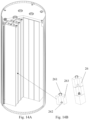
- Figs. 14A and 14B show the cross sectional views of the simulated storage tank for the operation test, which can simulate the real load of the spent fuel assembly and be used for the transfer and storage test and skill training of the spent fuel tank.
- the simulated storage tank includes an inner top cover 12, a cylinder body 13, a siphon block 14, an inflatable block 15, a simulated spent fuel grid 16 and a bottom plate 17.
- the inner top cover 12 is fixed to the cylinder body 13 only by a support screw bolt, and no welding is required. There is no cable penetrator on the inner top cover 12.
- the simulated spent fuel assembly 2 includes an upper tube seat 21, a square tube 22, lower tube seat 23, an electric heating rod 24, a cross bracket 25, and an assembly test block 26.
- the assembly test block 26 is a metal cylinder with square cross section, which is located in four storage chambers of the cross bracket 25.
- the weight of different types of spent fuel assemblies is simulated by layer by layer stacking, in order to complete the spent fuel tank hoisting, transfer and storage process operation.
- the assembly test block 26 is provided with a lifting handle 261, a bottom hole 262 and a main body 263.
- the lifting handle 261 is used for stacking operation, and the bottom hole 262 is used for stacking and nesting the lifting handle 261 step by step.
- the test method includes:
- the simulated spent fuel storage tank for a nuclear power station of the present invention can be used for thermal property identification and operation training test.
- the arrangement state and the thermal power of spent fuel assembly can be precisely simulated according to the actual loading and storage quantity and the heat release quantity of the spent fuel assemblies, and the thermal property identification of a spent fuel storage tank is achieved.
- the simulated spent fuel storage tank for a nuclear power station of the present invention can also be used to simulate vacuum drying, automatic welding, and cutting and retrieval operations in a real heating environment, to simulate a real spent fuel assembly load in order to perform storage tank transfer and storage operations, such that the skill level of operators can be improved, thereby preventing the occurrence of incidents caused by human factors.
Landscapes
- Engineering & Computer Science (AREA)
- Physics & Mathematics (AREA)
- Theoretical Computer Science (AREA)
- General Engineering & Computer Science (AREA)
- High Energy & Nuclear Physics (AREA)
- Business, Economics & Management (AREA)
- Educational Administration (AREA)
- Educational Technology (AREA)
- General Physics & Mathematics (AREA)
- Plasma & Fusion (AREA)
- Monitoring And Testing Of Nuclear Reactors (AREA)
Abstract
Description
- The present invention generally relates to nuclear power plants and, more particularly, relates to a simulated spent fuel storage tank for a nuclear power station.
- In view of the insufficient wet storage capacity of spent fuel pool in nuclear power plant, due to the inherent safety and modular storage economy arising from passive natural ventilation, spent fuel dry storage technology has been widely used in the world. A typical technical feature of spent fuel dry storage is that the spent fuel assembly is enclosed in sealed helium filled spent fuel storage tank and the spent fuel storage tank is stored in a concrete module via a transfer container, and the passive natural ventilation cooling is carried out by using natural ventilation.
- In order to ensure the thermal safety, the prior art has carried out the normal and accident numerical simulation analysis to ensure that the safety limit requirements are met. In terms of safety function, thermal numerical simulation has the advantages of convenient modeling, fast calculation, good visualization effect and low cost. However, due to the restriction of the complexity of equipment components and environmental conditions, it is necessary to simplify the calculation of boundary and material properties, and there is a deviation from the actual situation. In addition, due to the influence of structural discretization and the limitation of empirical formulas, there is a lack of physical thermal performance tests to verify the reliability of the calculated results.
- In terms of operational functions, the prior art needs to complete the welding of the spent fuel storage tanks, vacuum drying, module storage and the cutting and retrieval operations of spent fuel assemblies. On one hand, it is necessary to identify the process operation to prove the rationality of the equipment design and the manufacturing reliability. On the other hand, the lack of spent fuel storage tanks for skills training has led to insufficient operational skills of operators. For example, in the case of storage operation, when the spent fuel storage tank is lifted vertically or pushed into the module horizontally, once the deviation of the horizontal and vertical face-to-face will occur, the storage tank will jam and collide easily, which will bring about the safety risk.
- In view of the foregoing, what is needed, therefore, is to provide a simulated spent fuel storage tank for nuclear power station, so as to meet the practical requirements of thermal performance and process operation qualification of the spent fuel storage tank and skills training of the operator.
- One object of the present invention is to overcome the disadvantages of the prior art and provides a simulated spent fuel storage tank for nuclear power plant, which can meet the practical requirements of thermal performance and process operation qualification of spent fuel storage tank and skills training of operator.
- According to one embodiment of the present invention, a simulated spent fuel storage tank for nuclear power station includes a simulated storage tank, simulated spent fuel assemblies received in the simulated storage tank, and an electric heater, wherein the simulated spent fuel assemblies are electrically connected to the electric heater (3) by cables.
- According to one embodiment of the present invention, the simulated storage tank includes a bottom plate, a cylinder body arranged on the bottom plate, a simulated spent fuel grid in the cylinder body, and an inner top cover and an outer top cover independent from each other seated on a top of the cylinder body, wherein the inner top cover is provided with two bolting grooves, and a siphon block and a inflatable block at two sides of the cylinder body are inserted in the two bolting grooves respectively.
- According to one embodiment of the present invention, the bolting groove is provided with a layer of independent cover plate, and the cover plate is welded to the inner top cover.
- According to one embodiment of the present invention, an inner top cover support for supporting the inner top cover is provided on a top of the inner sidewall of the cylinder body, and a support screw is arranged on a top of the inner top cover support, and the support screw penetrates a bolting groove defined in the inner top cover to fix the inner top cover via a bolt.
- According to one embodiment of the present invention, the inner top cover is provided with a bolting groove, a clamp groove located above the bolting groove, and a bolting groove cover plate, the bolting groove is provided with a through hole, and the support screw on the top of the inner top cover support passes through the through hole and couples the inner top cover to the cylinder body via bolt thread connection, with the clamp groove sleeving on the inner top cover support for fixing the inner top cover support.
- According to one embodiment of the present invention, the outer top cover is formed with a first body, a first cable hole extending through the first body and a first cable penetrator disposed in the first cable hole, wherein the first cable penetrator seals the first cable hole via welding or via thread connection.
- According to one embodiment of the present invention, the first cable penetrator is a two-step cylinder with a cable penetrating passage in a middle thereof, for connecting a cable running through the inner top cover to the electric heater through the outer top cover.
- According to one embodiment of the present invention, the inner top cover includes a second body, a siphon block through hole and an inflatable block through hole defined in the second body, and a second cable hole and a second cable penetrator corresponding to the first cable hole and the first cable penetrator, and the second cable hole is provided with a cover plate.
- According to one embodiment of the present invention, the siphon block includes a siphon connection block, a drain pipe, and a quick connector for connecting the siphon connection block and the drain pipe.
- According to one embodiment of the present invention, the simulated spent fuel grid includes a plurality of storage chambers, with each storage chamber containing a set of simulated spent fuel assemblies, the simulated spent fuel assembly includes an upper tube seat, a lower tube seat, and a square tube between the upper tube seat and the lower tube seat, the square tube is provided with a cross bracket to divide the square tube into four storage units, and each storage unit stores an electric heating rod.
- According to one embodiment of the present invention, the electric heating rod includes a housing, a heating wire fixing rod seated in the housing, and an electric heating wire set around the heating wire fixing rod, wherein a filling insulation material is arranged between the housing and the electric heating wire, and the cable connecting the electric heating wire is formed with a protective sleeve.
- According to one embodiment of the present invention, the upper tube seat is provided with a base seat, a cable wire hole corresponding to the cable, and a protective platform arranged on an outer edge of the base seat.
- According to one embodiment of the present invention, the lower tube seat includes a base seat, a support leg for supporting the base seat, and a holding slot for sleeving and fixing the cross bracket.
- Compared with the prior art, the simulated spent fuel storage tank for the nuclear power plant of the invention can be used for thermal identification and operation training tests, and is based on the actual loading, storage quantity and heat release of the spent fuel assembly, it can accurately simulate the layout state and thermal power of the spent fuel assembly, and realize the thermal performance appraisal of the spent fuel storage tank, the problem that the existing spent fuel storage system cannot be verified by numerical simulation is solved. The simulated spent fuel storage tank for the nuclear power plant can also simulate vacuum drying, automatic welding and cutting and retrieving operations under the real heating environment, and can also simulate the load of the real spent fuel assembly to carry out the transfer and storage operations of the storage tank, the utility model can improve the skill level of the operator and avoid the occurrence of human-related events.
- In order to explain the technical solution of the embodiments of the present invention clearly, a brief introduction to the drawings required in the embodiments will be described as following. It should be understood that the drawings show only some embodiments of the present invention and, therefore, should not be seen as a limitation to the scope of the present invention. To one ordinary skilled in the art, other relevant drawings can also be obtained without creative work on the basis of the drawings.
-
Fig. 1 is a partially cross-sectional view of a simulated spent fuel storage tank for a nuclear power station according to one embodiment of the present invention; -
Fig. 2 is the top view of the simulated spent fuel storage tank for a nuclear power station of the present invention, in which the electric heater has been removed; -
Fig. 3 is a partially cross-sectional view of an outer top cover of the simulated spent fuel storage tank for a nuclear power station of the present invention; -
Fig. 4 is a partially cross-sectional view of an inner top cover of the simulated spent fuel storage tank for a nuclear power station of the present invention; -
Fig. 5 is another partially cross-sectional view of an inner top cover of the simulated spent fuel storage tank for a nuclear power station of the present invention; -
Fig. 6 is a partially assembled view of the inner top cover and the cylinder support in the simulated spent fuel storage tank for a nuclear power station of the present invention; -
Fig. 7 is a partially cross-sectional view of a cylinder body of the simulated spent fuel storage tank for a nuclear power station of the present invention; -
Fig. 8 is a perspective view of a simulated spent fuel grid in the simulated spent fuel storage tank for a nuclear power station of the present invention; -
Fig. 9 is a perspective view of a simulated spent fuel assembly in the simulated spent fuel storage tank for a nuclear power station of the present invention, showing an external structure of the simulated spent fuel assembly; -
Fig. 10 is a perspective view of the simulated spent fuel assembly in the simulated spent fuel storage tank for a nuclear power station of the present invention, showing the internal structure of the simulated spent fuel assembly; -
Fig. 11 is a cross-sectional view of the simulated spent fuel assembly in the simulated spent fuel storage tank for a nuclear power station of the present invention; -
Fig. 12 is a cross-sectional view of an electric heating rod in the simulated spent fuel storage tank for a nuclear power station of the present invention; -
Figs. 13A and 13B are perspective views of upper and lower tube seats of the simulated spent fuel assembly in the simulated spent fuel storage tank for a nuclear power station of the present invention; and -
Figs. 14A and 14B are perspective views of a simulated storage tank and an assembly test block of the simulated spent fuel storage tank for a nuclear power station of the present invention for use in load test. - The technical solution of the embodiments of the present invention will be described clearly and completely in combination with the drawings. Obviously, the embodiments described are only a part of the embodiments of the present invention, not all embodiments. Therefore, the following detailed description of embodiments of the present invention provided in the attached drawings is not intended to limit the scope of the present invention, but merely represents selected embodiments of the present invention. Based on the embodiments of the present invention, other embodiments obtained by one ordinary skilled in the art without creative work also fall within the scope of the present invention.
- Referring to
Fig. 1 , one embodiment of the present invention provides a simulated spent fuel storage tank for a nuclear power plant including a simulatedstorage tank 1, a simulated spentfuel assembly 2 contained in the simulatedstorage tank 1, and anelectric heater 3, wherein the simulated spentfuel assembly 2 is electrically connected with theelectric heater 3 via a cable to realize the electric heating function of the simulated spentfuel assembly 2. - Referring to
Figs. 1 and2 , the simulatedstorage tank 1 includes abottom plate 17, acylinder body 13 on thebottom plate 17, a simulated spentfuel grid 16 within thecylinder body 13, and aninner top cover 12 and anouter top cover 11 located at the top of thecylinder body 13 and independent from each other, wherein two penetration holes are arranged on theinner top cover 12, thesiphon block 14 and theinflatable block 15 located on both sides of thecylinder body 13 are nested in two penetration holes respectively (as shown inFig. 2 ) . Theouter top cover 11 and theinner top cover 12 are mutually independent circular cover plates for simulating automatic welding and cutting process operation. Thesiphon block 14 and theinflatable block 15 are independent from each other and are positioned on both sides of thecylinder body 13 respectively and are fixedly connected by welding. An independent small cover plate is arranged on the penetration hole of theinner top cover 12, and each small cover plate is connected with theinner top cover 12 by welding. - The
siphon block 14 and theinflatable block 15 are provided with quick connectors inside for simulating the operation of filling and draining the spent fuel storage tank with gas, pumping and vacuum drying and filling with helium gas. Thebottom plate 17 is provided with a water collecting tank. The drain pipe and thesiphon block 14 are fixed by screw thread to drain the boron-containing water in the tank through a siphon effect. The simulated spentfuel grid 16 is located inside thecylinder body 13, the simulated spentfuel grid 16 and thebottom plate 17 can be fixedly connected by welding or fastening, and the simulated spent fuel grid 6 and thecylinder body 13 can be fixed by filling or supporting. - Referring to
Fig. 3 , the outertop cover 11 is provided with afirst body 111, afirst cable hole 113 extending through thefirst body 111, and afirst cable penetrator 114 disposed in thefirst cable hole 113. Thefirst penetrator 114 seals thefirst cable hole 113 through a welding or threaded connection. Theweld groove 112 can adopt V-type groove with different structure forms to simulate the automatic welding operation of the storage tank cover plate and the cutting and retrieving operation of the cover plate. Thefirst cable hole 113 may be provided with one or more, and in the embodiment shown inFig. 3 , four first cable holes 113 are provided. Thefirst cable penetrator 114 is a two-step cylinder defining a cable penetrates passage in a middle thereof, which is used for connecting the cable which penetrates from the innertop cover 12 to theelectric heater 3 through the outertop cover 11. - Referring to
Figs. 4 and 5 , the innertop cover 12 includes asecond body 121, a siphon block perforating hole and an inflatableblock perforating hole 122 provided on thesecond body 121, and asecond cable hole 124 and asecond cable penetrator 125 arranged corresponding to thefirst cable hole 113 and thefirst cable penetrator 114, and thesecond cable hole 124 is provided with acover plate 123. The siphon block and the inflatable block have two perforatingholes 122, which are equidistant distributed at both ends through the center of thecover plate 123, and are used for sleeving the siphonblock 14 and theinflatable block 15 respectively. - Referring to
Figs. 6 and 7 , theinner side wall 131 of thecylinder body 13 is provided with an innertop cover support 132 for supporting the innertop cover 12, and the top of the innertop cover support 132 is provided with asupport screw 133, thesupport screw 133 penetrates the boltinggroove 126 arranged on the innertop cover 12, to fix the innertop cover 12 via bolt connection. - Referring to
Figs. 4 and7 , the innertop cover 12 is provided with a boltinggroove 126, aclamp groove 128 above the boltinggroove 126, and a boltinggroove cover plate 127. The boltinggroove 126 is provided with a perforated hole, and the top of the innertop cover support 132 is provided with a supportingscrew 133, which passes through the perforated hole and fixes the innertop cover 12 to thecylinder 13 through a bolt thread connection. In installation of the innertop cover 12, theclamp groove 128 is sleeved on the innertop cover support 132, to support and fix the innertop cover 12. - Referring to
Fig. 4 , there are four boltinggrooves 126, uniformly distributed in concentric, each boltinggroove 126 defines a perforated hole, for use in the full-load and no-load tests of the spent fuel assemblies shown inFigs. 3 and4 . The support screw of the inner top cover is passed through the perforated hole, and a bolt is mounted on the upper part of the innertop cover 12, to fix the innertop cover 12 in thecylinder body 13, to ensure that the simulated spentfuel assembly 2 does not slip out in horizontal operation and protect the simulated spentfuel grid 16. - Referring to
Fig. 7 , the siphonblock 14 includes a siphon connection block 141, adrain pipe 143, and aquick connector 142 connecting the siphon connection block 141 and thedrain pipe 143. The difference between theinflatable block 15 and the siphonblock 14 lies only in the absence of adrain pipe 143. In this manner, the device can be used for simulating the operation of inflatable drainage, vacuum drying and helium filling. - Referring to
Fig. 8 , the simulated spentfuel grid 16 includes several storage chambers, each storage chamber containing a group of simulated spentfuel assemblies 2. The simulated spentfuel grid 16 may consist of integral panels or single division plates welded together. In the illustrated embodiment, the simulated spentfuel grid 16 includes totally storage chambers, each containing a group of simulated spentfuel assemblies 2. - Referring to
Figs. 9 to 11 , the simulated spentfuel assembly 2 includes anupper tube seat 21, alower tube seat 23, and asquare tube 22 between theupper tube seat 21 and thelower tube seat 23, theupper tube seat 21, thesquare tube 22 and thelower tube seat 23 are fixedly connected by welding, and are generally rectangular bodies with square cross sections. Thesquare tube 22 is provided with across bracket 25 and divided into four storage units, each of which stores anelectric heating rod 24. To facilitate fixing, across bracket 25 is nested at the outside of eachelectric heating rod 24 from the top, middle and bottom positions. Theelectric heating rod 24 preferably is made from stainless steel, with a cylindrical middle section and two spherical crowns at two ends. - Referring to
Fig. 12 , theelectric heating rod 24 includes ahousing 241, a heatingwire fixing rod 244 seated in thehousing 241, and anelectric heating wire 242 arranged around the heatingwire fixing rod 244, wherein a filling insulation material 243(such as magnesium oxide) is arranged between thehousing 241 and theelectric heating wire 242, and thecable 246 connecting theelectric heating wire 242 is provided with aprotective sleeve 245. In the illustrated embodiment, theelectric heating wire 242 is a U-shaped loop coiled around the vertical heatingwire fixing rod 244 and located inside thehousing 241 of theelectric heating rod 24. - In order to improve the accuracy of thermal performance verification of the spent fuel storage tanks, in actual operation process, the spent fuel rods in nuclear power station are equipped with a compression spring at the upper end thereof and no fuel pellets release heat. Therefore, the upper part of the inner cavity of the
electric heating rod 24 of the present invention has a hollow structure, which is used for simulating the non-active heating segment of the spent fuel rod. The size of the non-active segment can be verified according to different types of spent fuel assembly. For example, the size of the non-active segment can be about 170cm and the size of the active segment can be about 3662cm. According to the decay heat characteristics of spent fuel assembly, the power range of each group ofelectric heating rods 24 is from 0.6kw to 2kw. - Referring to
Figs. 13A and 13B , theupper tube seat 21 is a square metal member located on the top of thesquare tube 22. Theupper tube seat 21 is provided with abase seat 211, acable wire hole 212 corresponding to the cable, and aprotective platform 213 arranged on the outer edge of thebase seat 211. There are four cable wire holes 212, corresponding to theelectric heating rods 24, for pulling out thecables 246 from the top of the simulated spentfuel assembly 2 and connecting with the cable penetrator on the top cover. Thelower tube seat 23 is a square metal member positioned at the bottom of thesquare tube 22. Thelower tube seat 23 includes abase seat 231, asupport leg 232 for supporting thebase seat 231, and a holdingslot 233 for sleeving thecross bracket 25. - 1. The simulated spent fuel storage tank for a nuclear power station of the present invention can be used for thermal performance identification test, and the test method includes the steps of:
- placing an
electric heating rod 24 in the simulated spentfuel assembly 2, and encapsulating theupper tube seat 21 and thesquare tube 22; - installing the simulated spent
fuel assembly 2 in storage units of simulated spentfuel grid 16; - collecting and leading out all of the cables of the simulated spent
fuel assemblies 2 from the cable penetrator of the innertop cover 12, each eight simulated spentfuel assemblies 2 being set as one group; - sealing the inner
top cover 12 and thecylinder body 13 by welding; - welding the cable penetrator of the inner
top cover 12; - filling helium gas into the simulated storage tank through an
inflatable block 15 to discharge the air in the tank from the bottom of the drainage pipe; - sealing and welding the siphon
block 14, theinflatable block 15 and the outertop cover 11; - connecting all the cables of the simulated spent
fuel assemblies 2 in advance and pulling out the cables from the penetrator of the outertop cover 11; - connecting and sealing the outer
top cover 11 and thecylinder body 13; - connecting the collected cables to the
electric heater 3; - simulating the spent fuel assemblies with different heat release rate by adjusting the power of each group of electric heating rods in accordance with the spent fuel management strategy of the nuclear power station;
- setting temperature monitoring points on the outside of the spent fuel storage tank according to requirement, comparing the results with the results of thermal numerical simulation analysis, so as to verify the consistency and reliability of the calculated results.
- placing an
- 2. The simulated spent fuel storage tank for a nuclear power station of the present invention can also be simultaneously used for technological tests and skills training such as vacuum drying, automatic welding, cutting and retrieval in the hot environment:
- placing the
electric heating rod 24 inside the simulated spentfuel assembly 2, encapsulating theupper tube seat 21 and thesquare tube 22; - installing the simulated spent
fuel assembly 2 inside the storage units of the simulated spentfuel grid 16; - collecting and leading out all of the cables of the simulated spent
fuel assemblies 2 from the cable penetrator of the innertop cover 12, each eight simulated spentfuel assemblies 2 being set as one group; - connecting all cables collected to the
electric heater 3; - simulating the spent fuel assemblies with corresponding heat release rate by adjusting the power of each group of electric heating rods in accordance with the spent fuel management strategy of the nuclear power station; and
- filling water into the simulated storage tank by the siphon
block 14.
- placing the
- The welding machine is arranged on the top of the inner
top cover 12, and the innertop cover 12 and thecylinder 13 are sealed by welding to simulate the automatic welding operation under the hot state environment. Filling helium gas into the simulated tank through theexhaust block 15 to drain water away from the siphonblock 14 to simulate the operation of charging and draining; The siphonblock 14 and theexhaust block 15 are connected with the vacuum drying system to simulate the vacuum drying operation under the hot state environment; then the cutting machine is arranged on the top of theinner cover 12, and the welding seam of theinner cover 12 is cut, simulation of hot environment in the cutting operation. - 3. The simulated spent fuel storage tank for a nuclear power station can be used for the transfer and storage test.
-
Figs. 14A and 14B show the cross sectional views of the simulated storage tank for the operation test, which can simulate the real load of the spent fuel assembly and be used for the transfer and storage test and skill training of the spent fuel tank. - The simulated storage tank includes an inner
top cover 12, acylinder body 13, a siphonblock 14, aninflatable block 15, a simulated spentfuel grid 16 and abottom plate 17. The innertop cover 12 is fixed to thecylinder body 13 only by a support screw bolt, and no welding is required. There is no cable penetrator on the innertop cover 12. - The simulated spent
fuel assembly 2 includes anupper tube seat 21, asquare tube 22,lower tube seat 23, anelectric heating rod 24, across bracket 25, and anassembly test block 26. Theassembly test block 26 is a metal cylinder with square cross section, which is located in four storage chambers of thecross bracket 25. The weight of different types of spent fuel assemblies is simulated by layer by layer stacking, in order to complete the spent fuel tank hoisting, transfer and storage process operation. Theassembly test block 26 is provided with alifting handle 261, abottom hole 262 and amain body 263. The lifting handle 261 is used for stacking operation, and thebottom hole 262 is used for stacking and nesting the lifting handle 261 step by step. - When used for spent fuel assembly transfer storage load test, there is no need to weld the top cover and the cable penetrator. The test method includes:
- First, a modular test block is used to place the
cross brackets 25 in the four storage units in a step-by-step stacking manner; - Second, a screw at the top of the support of the inner cover of the
cylinder 13 is passed through the through hole; - Finally, a bolt is used on the upper part of the inner
top cover 12 to secure the innertop cover 12 in thecylinder body 13, to ensure that the simulated spentfuel assembly 2 does not slip out in horizontal operation. - Compared with the prior art, the simulated spent fuel storage tank for a nuclear power station of the present invention can be used for thermal property identification and operation training test. The arrangement state and the thermal power of spent fuel assembly can be precisely simulated according to the actual loading and storage quantity and the heat release quantity of the spent fuel assemblies, and the thermal property identification of a spent fuel storage tank is achieved. The simulated spent fuel storage tank for a nuclear power station of the present invention can also be used to simulate vacuum drying, automatic welding, and cutting and retrieval operations in a real heating environment, to simulate a real spent fuel assembly load in order to perform storage tank transfer and storage operations, such that the skill level of operators can be improved, thereby preventing the occurrence of incidents caused by human factors.
- The above described embodiments are only preferred embodiments of the present invention, and are not intended to limit the scope of the present invention. Any modification, equivalent replacement and improvement within the spirit and principle of the present invention should be included in the protection scope of the present invention.
Claims (13)
- A simulated spent fuel storage tank for nuclear power station, characterized in that the simulated spent fuel storage tank for nuclear power station comprises a simulated storage tank (1), simulated spent fuel assemblies (2) received in the simulated storage tank (1), and an electric heater (3), wherein the simulated spent fuel assemblies (2) are electrically connected to the electric heater (3) by cables.
- The simulated spent fuel storage tank for nuclear power station according to claim 1, characterized in that the simulated storage tank (1) comprises a bottom plate (17), a cylinder body (13) arranged on the bottom plate (17), a simulated spent fuel grid (16) in the cylinder body (13), and an inner top cover (12) and an outer top cover (11) independent from each other seated on a top of the cylinder body (13), wherein the inner top cover (12) is provided with two bolting grooves, and a siphon block (14) and a inflatable block (15) at two sides of the cylinder body (13) are inserted in the two bolting grooves respectively.
- The simulated spent fuel storage tank for nuclear power station according to claim 2, characterized in that the bolting groove is provided with a layer of independent cover plate, and the cover plate is welded to the inner top cover (12).
- The simulated spent fuel storage tank for nuclear power station according to claim 2, characterized in that an inner top cover support (132) for supporting the inner top cover (12) is provided on a top of the inner sidewall (131) of the cylinder body (13), and a support screw (133) is arranged on a top of the inner top cover support (132), and the support screw (133) penetrates a bolting groove (126) defined in the inner top cover (12) to fix the inner top cover (12) via a bolt.
- The simulated spent fuel storage tank for nuclear power station according to claim 4, characterized in that the inner top cover (12) is provided with a bolting groove (126), a clamp groove (128) located above the bolting groove (126), and a bolting groove cover plate (127), the bolting groove (126) is provided with a through hole, and the support screw (133) on the top of the inner top cover support (132) passes through the through hole and couples the inner top cover (12) to the cylinder body (13) via bolt thread connection, with the clamp groove (128) sleeving on the inner top cover support (132) for fixing the inner top cover support (132).
- The simulated spent fuel storage tank for nuclear power station according to claim 2, characterized in that the outer top cover (11) is formed with a first body (111), a first cable hole (113) extending through the first body (111), and a first cable penetrator (114) disposed in the first cable hole (113), wherein the first cable penetrator (114) seals the first cable hole (113) via welding or thread connection.
- The simulated spent fuel storage tank for nuclear power station according to claim 6, characterized in that the first cable penetrator (114) is a two-step cylinder with a cable penetrating passage in a middle thereof, for connecting a cable running through the inner top cover (12) to the electric heater (3) through the outer top cover (11).
- The simulated spent fuel storage tank for nuclear power station according to claim 6, characterized in that the inner top cover (12) comprises a second body (121), a siphon block through hole and an inflatable block through hole defined in the second body (121), and a second cable hole (124) and a second cable penetrator (125) corresponding to the first cable hole (113) and the first cable penetrator (114), and the second cable hole (124) is provided with a cover plate.
- The simulated spent fuel storage tank for nuclear power station according to claim 2, characterized in that the siphon block (14) comprises a siphon connection block (141), a drain pipe (143), and a quick connector (142) for connecting the siphon connection block (141) and the drain pipe (143).
- The simulated spent fuel storage tank for nuclear power station according to claim 2, characterized in that the simulated spent fuel grid (16) comprises a plurality of storage chambers, with each storage chamber containing a set of simulated spent fuel assemblies (2), the simulated spent fuel assembly (2) comprises an upper tube seat (21), a lower tube seat (23), and a square tube (22) between the upper tube seat (21) and the lower tube seat (23), the square tube (22) is provided with a cross bracket (25) to divide the square tube (22) into four storage units, and each storage unit stores an electric heating rod (24).
- The simulated spent fuel storage tank for nuclear power station according to claim 10, characterized in that the electric heating rod (24) comprises a housing (241), a heating wire fixing rod (244) seated in the housing (241), and an electric heating wire (242) set around the heating wire fixing rod (244), wherein a filling insulation material (243) is arranged between the housing (241) and the electric heating wire (242), and the cable (246) connecting the electric heating wire (242) is formed with a protective sleeve (245).
- The simulated spent fuel storage tank for nuclear power station according to claim 10, characterized in that the upper tube seat (21) is provided with a base seat (211), a cable wire hole (212) corresponding to the cable (246), and a protective platform (213) arranged on an outer edge of the base seat (211).
- The simulated spent fuel storage tank for nuclear power station according to claim 10, characterized in that the lower tube seat (23) comprises a base seat (231), a support leg (232) for supporting the base seat (231), and a holding slot (233) for sleeving and fixing the cross bracket (25).
Applications Claiming Priority (2)
| Application Number | Priority Date | Filing Date | Title |
|---|---|---|---|
| CN202011096864.XA CN112635085B (en) | 2020-10-14 | 2020-10-14 | Simulated spent fuel storage tank for nuclear power station |
| PCT/CN2020/134729 WO2021227470A1 (en) | 2020-10-14 | 2020-12-09 | Simulated spent fuel storage tank for nuclear power station |
Publications (3)
| Publication Number | Publication Date |
|---|---|
| EP4243033A1 true EP4243033A1 (en) | 2023-09-13 |
| EP4243033A4 EP4243033A4 (en) | 2024-11-20 |
| EP4243033B1 EP4243033B1 (en) | 2026-02-18 |
Family
ID=75302899
Family Applications (1)
| Application Number | Title | Priority Date | Filing Date |
|---|---|---|---|
| EP20935478.6A Active EP4243033B1 (en) | 2020-10-14 | 2020-12-09 | Simulated spent fuel storage tank for nuclear power station |
Country Status (3)
| Country | Link |
|---|---|
| EP (1) | EP4243033B1 (en) |
| CN (1) | CN112635085B (en) |
| WO (1) | WO2021227470A1 (en) |
Families Citing this family (1)
| Publication number | Priority date | Publication date | Assignee | Title |
|---|---|---|---|---|
| CN115229470B (en) * | 2022-08-29 | 2023-07-18 | 华能山东石岛湾核电有限公司 | A disassembly device and method |
Family Cites Families (7)
| Publication number | Priority date | Publication date | Assignee | Title |
|---|---|---|---|---|
| CN105261402B (en) * | 2015-09-07 | 2017-11-17 | 深圳中广核工程设计有限公司 | Spent nuclear fuel in nuclear power plant dry storage fuel tank |
| CN106229018A (en) * | 2016-08-17 | 2016-12-14 | 中国核电工程有限公司 | A kind of heater |
| JP6985188B2 (en) * | 2018-03-19 | 2021-12-22 | 株式会社神戸製鋼所 | Heat transfer test equipment for containers used to transport and / or store spent fuel |
| CN208317038U (en) * | 2018-05-29 | 2019-01-01 | 华北电力大学 | A kind of novel electric heating stick |
| CN109060319A (en) * | 2018-05-29 | 2018-12-21 | 华北电力大学 | A kind of experimental rig and method for nuclear power station spent fuel reservoir nozzle sensibility |
| CN209674898U (en) * | 2018-11-19 | 2019-11-22 | 清华大学天津高端装备研究院 | A kind of spent fuel geological storage tank |
| CN210403223U (en) * | 2019-06-18 | 2020-04-24 | 清华大学天津高端装备研究院 | Heater for spent fuel geological storage temperature test |
-
2020
- 2020-10-14 CN CN202011096864.XA patent/CN112635085B/en active Active
- 2020-12-09 WO PCT/CN2020/134729 patent/WO2021227470A1/en not_active Ceased
- 2020-12-09 EP EP20935478.6A patent/EP4243033B1/en active Active
Also Published As
| Publication number | Publication date |
|---|---|
| EP4243033B1 (en) | 2026-02-18 |
| CN112635085B (en) | 2022-05-31 |
| CN112635085A (en) | 2021-04-09 |
| WO2021227470A1 (en) | 2021-11-18 |
| EP4243033A4 (en) | 2024-11-20 |
Similar Documents
| Publication | Publication Date | Title |
|---|---|---|
| US8718220B2 (en) | Manifold system for the ventilated storage of high level waste and a method of using the same to store high level waste in a below-grade environment | |
| JP5784515B2 (en) | Reactor fuel removal method and apparatus | |
| EP4243033B1 (en) | Simulated spent fuel storage tank for nuclear power station | |
| US20150377756A1 (en) | Water jet peening compressive residual stress test method, test device, and test facility | |
| JP6670005B2 (en) | Post-Use Nuclear Fuel Passive Cooling System Using Heat Pipe | |
| Kakodkar | Evolution of nuclear reactor containments in India: Addressing the present day challenges | |
| JPH11281786A (en) | Reactor containment vessel | |
| JPH03115998A (en) | Method and structure for shielding radiation from reactor internals in storage state | |
| JP2005099013A (en) | Lid assembly | |
| CN108665985A (en) | A kind of equivalent fuel assembly of bunkering screen work shock test | |
| WO2025167112A1 (en) | Offshore nuclear power platform and reactor-compartment arrangement structure of offshore nuclear power platform | |
| Suzuki et al. | ROSA-V large scale test facility (LSTF) system description for the third and fourth simulated fuel assemblies | |
| CN108362459A (en) | A kind of 1x9 types spent fuel storage rack shock test part | |
| CN108645584A (en) | A kind of 3x3 types spent fuel storage rack shock test part | |
| US9375813B2 (en) | Nozzle repairing method and nuclear reactor vessel | |
| US10600519B2 (en) | Nuclear reactor module | |
| CN208505562U (en) | A 3x3 type spent fuel storage grid seismic test piece | |
| JP5916371B2 (en) | Underwater plate bending apparatus and underwater reracing method using the apparatus | |
| CN209674898U (en) | A kind of spent fuel geological storage tank | |
| US20030076917A1 (en) | Device for storage of hazardous material | |
| Estevez-Albuja et al. | AP1000® passive cooling containment analysis of a double-ended LBLOCA with a 3D GOTHIC model | |
| CN220984183U (en) | Water tank device of nuclear reactor containment and nuclear reactor containment equipment | |
| CN118486231A (en) | Nuclear power station fuel pool presentation device | |
| CN216928047U (en) | Safety shell | |
| KR20160050464A (en) | Method of specimen test unit of the reactor vessel and specimen test unit of the reactor vessel |
Legal Events
| Date | Code | Title | Description |
|---|---|---|---|
| STAA | Information on the status of an ep patent application or granted ep patent |
Free format text: STATUS: THE INTERNATIONAL PUBLICATION HAS BEEN MADE |
|
| PUAI | Public reference made under article 153(3) epc to a published international application that has entered the european phase |
Free format text: ORIGINAL CODE: 0009012 |
|
| STAA | Information on the status of an ep patent application or granted ep patent |
Free format text: STATUS: REQUEST FOR EXAMINATION WAS MADE |
|
| 17P | Request for examination filed |
Effective date: 20230512 |
|
| AK | Designated contracting states |
Kind code of ref document: A1 Designated state(s): AL AT BE BG CH CY CZ DE DK EE ES FI FR GB GR HR HU IE IS IT LI LT LU LV MC MK MT NL NO PL PT RO RS SE SI SK SM TR |
|
| DAV | Request for validation of the european patent (deleted) | ||
| DAX | Request for extension of the european patent (deleted) | ||
| REG | Reference to a national code |
Ref country code: DE Ref legal event code: R079 Free format text: PREVIOUS MAIN CLASS: G21C0017060000 Ipc: G21F0005012000 Ref country code: DE Ref legal event code: R079 Ref document number: 602020067323 Country of ref document: DE Free format text: PREVIOUS MAIN CLASS: G21C0017060000 Ipc: G21F0005012000 |
|
| A4 | Supplementary search report drawn up and despatched |
Effective date: 20241017 |
|
| RIC1 | Information provided on ipc code assigned before grant |
Ipc: G09B 9/00 20060101ALI20241011BHEP Ipc: G21F 5/06 20060101ALI20241011BHEP Ipc: G21F 5/012 20060101AFI20241011BHEP |
|
| GRAP | Despatch of communication of intention to grant a patent |
Free format text: ORIGINAL CODE: EPIDOSNIGR1 |
|
| STAA | Information on the status of an ep patent application or granted ep patent |
Free format text: STATUS: GRANT OF PATENT IS INTENDED |
|
| INTG | Intention to grant announced |
Effective date: 20250710 |
|
| GRAS | Grant fee paid |
Free format text: ORIGINAL CODE: EPIDOSNIGR3 |
|
| RAP3 | Party data changed (applicant data changed or rights of an application transferred) |
Owner name: CHINA NUCLEAR POWER ENGINEERING CO., LTD. Owner name: GUANGDONG NUCLEAR POWER JOINT VENTURE CO., LTD. Owner name: CHINA GENERAL NUCLEAR POWER CORPORATION Owner name: CGN POWER CO., LTD. |
|
| GRAA | (expected) grant |
Free format text: ORIGINAL CODE: 0009210 |
|
| STAA | Information on the status of an ep patent application or granted ep patent |
Free format text: STATUS: THE PATENT HAS BEEN GRANTED |
|
| AK | Designated contracting states |
Kind code of ref document: B1 Designated state(s): AL AT BE BG CH CY CZ DE DK EE ES FI FR GB GR HR HU IE IS IT LI LT LU LV MC MK MT NL NO PL PT RO RS SE SI SK SM TR |
|
| REG | Reference to a national code |
Ref country code: CH Ref legal event code: F10 Free format text: ST27 STATUS EVENT CODE: U-0-0-F10-F00 (AS PROVIDED BY THE NATIONAL OFFICE) Effective date: 20260218 Ref country code: GB Ref legal event code: FG4D |
|
| REG | Reference to a national code |
Ref country code: IE Ref legal event code: FG4D |
|
| REG | Reference to a national code |
Ref country code: DE Ref legal event code: R096 Ref document number: 602020067323 Country of ref document: DE |