EP4243002A1 - Manipulation simulator and simulation method - Google Patents
Manipulation simulator and simulation method Download PDFInfo
- Publication number
- EP4243002A1 EP4243002A1 EP21903212.5A EP21903212A EP4243002A1 EP 4243002 A1 EP4243002 A1 EP 4243002A1 EP 21903212 A EP21903212 A EP 21903212A EP 4243002 A1 EP4243002 A1 EP 4243002A1
- Authority
- EP
- European Patent Office
- Prior art keywords
- simulated
- blood vessel
- model
- aorta
- vessel
- Prior art date
- Legal status (The legal status is an assumption and is not a legal conclusion. Google has not performed a legal analysis and makes no representation as to the accuracy of the status listed.)
- Pending
Links
Images




Classifications
-
- G—PHYSICS
- G09—EDUCATION; CRYPTOGRAPHY; DISPLAY; ADVERTISING; SEALS
- G09B—EDUCATIONAL OR DEMONSTRATION APPLIANCES; APPLIANCES FOR TEACHING, OR COMMUNICATING WITH, THE BLIND, DEAF OR MUTE; MODELS; PLANETARIA; GLOBES; MAPS; DIAGRAMS
- G09B23/00—Models for scientific, medical, or mathematical purposes, e.g. full-sized devices for demonstration purposes
- G09B23/28—Models for scientific, medical, or mathematical purposes, e.g. full-sized devices for demonstration purposes for medicine
- G09B23/285—Models for scientific, medical, or mathematical purposes, e.g. full-sized devices for demonstration purposes for medicine for injections, endoscopy, bronchoscopy, sigmoidscopy, insertion of contraceptive devices or enemas
-
- G—PHYSICS
- G09—EDUCATION; CRYPTOGRAPHY; DISPLAY; ADVERTISING; SEALS
- G09B—EDUCATIONAL OR DEMONSTRATION APPLIANCES; APPLIANCES FOR TEACHING, OR COMMUNICATING WITH, THE BLIND, DEAF OR MUTE; MODELS; PLANETARIA; GLOBES; MAPS; DIAGRAMS
- G09B19/00—Teaching not covered by other main groups of this subclass
- G09B19/24—Use of tools
-
- G—PHYSICS
- G09—EDUCATION; CRYPTOGRAPHY; DISPLAY; ADVERTISING; SEALS
- G09B—EDUCATIONAL OR DEMONSTRATION APPLIANCES; APPLIANCES FOR TEACHING, OR COMMUNICATING WITH, THE BLIND, DEAF OR MUTE; MODELS; PLANETARIA; GLOBES; MAPS; DIAGRAMS
- G09B23/00—Models for scientific, medical, or mathematical purposes, e.g. full-sized devices for demonstration purposes
- G09B23/28—Models for scientific, medical, or mathematical purposes, e.g. full-sized devices for demonstration purposes for medicine
-
- G—PHYSICS
- G09—EDUCATION; CRYPTOGRAPHY; DISPLAY; ADVERTISING; SEALS
- G09B—EDUCATIONAL OR DEMONSTRATION APPLIANCES; APPLIANCES FOR TEACHING, OR COMMUNICATING WITH, THE BLIND, DEAF OR MUTE; MODELS; PLANETARIA; GLOBES; MAPS; DIAGRAMS
- G09B23/00—Models for scientific, medical, or mathematical purposes, e.g. full-sized devices for demonstration purposes
- G09B23/28—Models for scientific, medical, or mathematical purposes, e.g. full-sized devices for demonstration purposes for medicine
- G09B23/286—Models for scientific, medical, or mathematical purposes, e.g. full-sized devices for demonstration purposes for medicine for scanning or photography techniques, e.g. X-rays, ultrasonics
-
- G—PHYSICS
- G09—EDUCATION; CRYPTOGRAPHY; DISPLAY; ADVERTISING; SEALS
- G09B—EDUCATIONAL OR DEMONSTRATION APPLIANCES; APPLIANCES FOR TEACHING, OR COMMUNICATING WITH, THE BLIND, DEAF OR MUTE; MODELS; PLANETARIA; GLOBES; MAPS; DIAGRAMS
- G09B23/00—Models for scientific, medical, or mathematical purposes, e.g. full-sized devices for demonstration purposes
- G09B23/28—Models for scientific, medical, or mathematical purposes, e.g. full-sized devices for demonstration purposes for medicine
- G09B23/30—Anatomical models
-
- G—PHYSICS
- G09—EDUCATION; CRYPTOGRAPHY; DISPLAY; ADVERTISING; SEALS
- G09B—EDUCATIONAL OR DEMONSTRATION APPLIANCES; APPLIANCES FOR TEACHING, OR COMMUNICATING WITH, THE BLIND, DEAF OR MUTE; MODELS; PLANETARIA; GLOBES; MAPS; DIAGRAMS
- G09B23/00—Models for scientific, medical, or mathematical purposes, e.g. full-sized devices for demonstration purposes
- G09B23/28—Models for scientific, medical, or mathematical purposes, e.g. full-sized devices for demonstration purposes for medicine
- G09B23/30—Anatomical models
- G09B23/303—Anatomical models specially adapted to simulate circulation of bodily fluids
-
- G—PHYSICS
- G09—EDUCATION; CRYPTOGRAPHY; DISPLAY; ADVERTISING; SEALS
- G09B—EDUCATIONAL OR DEMONSTRATION APPLIANCES; APPLIANCES FOR TEACHING, OR COMMUNICATING WITH, THE BLIND, DEAF OR MUTE; MODELS; PLANETARIA; GLOBES; MAPS; DIAGRAMS
- G09B23/00—Models for scientific, medical, or mathematical purposes, e.g. full-sized devices for demonstration purposes
- G09B23/28—Models for scientific, medical, or mathematical purposes, e.g. full-sized devices for demonstration purposes for medicine
- G09B23/30—Anatomical models
- G09B23/34—Anatomical models with removable parts
-
- G—PHYSICS
- G09—EDUCATION; CRYPTOGRAPHY; DISPLAY; ADVERTISING; SEALS
- G09B—EDUCATIONAL OR DEMONSTRATION APPLIANCES; APPLIANCES FOR TEACHING, OR COMMUNICATING WITH, THE BLIND, DEAF OR MUTE; MODELS; PLANETARIA; GLOBES; MAPS; DIAGRAMS
- G09B9/00—Simulators for teaching or training purposes
Definitions
- the present invention relates to a surgical simulator and a simulation method.
- JP 2015-64487 A discloses a surgical simulator used for training in Thoracic Endovascular Aortic Repair in which a stent graft is deployed in a thoracic aorta model mimicking the thoracic aorta of a human body.
- a thoracic aorta aneurysm may recur after an operation to replace a part of the thoracic aorta with an artificial blood vessel.
- Thoracic Endovascular Aortic Repair has enabled percutaneous deployment of a stent graft in a lesion of the thoracic aorta (aneurysm portion or dissected portion) even in retreatment cases.
- a stent graft may be deployed in the descending aorta by Thoracic Endovascular Aortic Repair in the early phase.
- a stent graft may be deployed in the descending aorta by Thoracic Endovascular Aortic Repair in the early phase.
- a surgical simulator disclosed in JP 2015-64487 A is not designed to be used for training to deal with such complicated cases and does not reproduce a feeling of graft insertion which a doctor experiences in a complicated case.
- the surgical simulator disclosed in JP 2015-64487 A is not a tool for learning stenting while actually using a CT scan.
- the invention has been made in light of the problems, and an object of the invention is to provide a surgical simulator and a simulation method that enable simulation of Thoracic Endovascular Aortic Repair for complicated thoracic aorta cases and enable efficient learning of Thoracic Endovascular Aortic Repair.
- An aspect of the invention is a surgical simulator including a blood vessel model, the blood vessel model including an aorta model mimicking a case of replacing a part of the thoracic aorta of a human body with an artificial blood vessel, and the aorta model including a simulated vessel and an artificial blood vessel, or a medical device, connected to the simulated vessel.
- Another aspect of the invention is a simulation method using the surgical simulator, the method involving: a water supplying step for supplying water in the blood vessel model; a guiding step for operating a catheter while the water flows in the blood vessel model to guide a stent graft embedded in a tip of the catheter into the aorta model; and an expanding step for expanding the stent graft after the guiding step.
- the aorta model includes the simulated vessel and the artificial blood vessel, which enables simulation of Thoracic Endovascular Aortic Repair for complicated thoracic aorta cases. Therefore, it is possible to learn Thoracic Endovascular Aortic Repair efficiently.
- a surgical simulator 10 is used for training in Thoracic Endovascular Aortic Repair of the thoracic aorta.
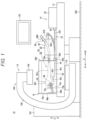
- the surgical simulator 10 includes an operating table 12 installed on a floor 300, a simulator body 14 located on the operating table 12, and a radiography device 16 installed on the floor 300.
- the operating table 12 extends in one direction (direction of arrow X).
- the operating table 12 can move up and down in the height direction (direction of arrow Z).
- the simulator body 14 includes a tank 18, a pump 20, a connection circuit 22, and a blood vessel model 24.
- the tank 18 can be comprised, for example, polyvinyl chloride (PVC).
- PVC polyvinyl chloride
- the tank 18 is disposed at one end of the operating table 12 in the longitudinal direction (direction of arrow X1).
- the tank 18 is located substantially at the center of the operating table 12 in the transverse direction (width direction, direction of arrow Y).
- the tank 18 can have a box shape with an open top.
- the tank 18 is formed of a transparent plastic.
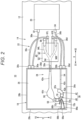
- the tank 18 includes a quadrangular bottom wall 26 (see Fig. 2 ) and first to fourth side walls 28a to 28d protruding in the height direction (direction of arrow Z) from each side of the bottom wall 26.
- the first side wall 28a is located at an end of the bottom wall 26 in a direction of arrow Y1 (one side of the operating table 12 in the transverse direction).
- the second side wall 28b is located at an end of the bottom wall 26 in a direction of arrow Y2 (the other side of the operating table 12 in the transverse direction).
- the third side wall 28c is located at an end of the bottom wall 26 in the direction of arrow X1.
- the fourth side wall 28d is located at an end of the bottom wall 26 in a direction of arrow X2 (opposite to the direction of arrow X1).
- the fourth side wall 28d is provided with a first tube connector 30a, a second tube connector 30b, a third tube connector 30c, a fourth tube connector 30d, and a fifth tube connector 30e.
- the material, shape, and size of the tank 18 are designed appropriately.
- the pump 20 is used for suctioning water in the tank 18 and supplying the water to the blood vessel model 24.
- the pump 20 supplies the water to the blood vessel model 24 in such a manner that pressure comparable to arterial pressure is applied to the blood vessel model 24.
- the pump 20 includes a suction port 32 for suctioning the water and a discharge port 34 for discharging the water.
- the connection circuit 22 is used for circulating the water in the tank 18 through the blood vessel model 24.
- the connection circuit 22 includes a first connecting tube 36a, a second connecting tube 36b, a third connecting tube 36c, and a fourth connecting tube 36d.
- the first connecting tube 36a forms a channel for guiding the water in the tank 18 to the pump 20.
- the first connecting tube 36a connects the first tube connector 30a and the suction port 32 of the pump 20.
- a lumen of the first connecting tube 36a communicates with the tank 18 through the first tube connector 30a.
- the second connecting tube 36b forms a channel for guiding the water discharged from the pump 20 into the blood vessel model 24.
- the second connecting tube 36b connects the discharge port 34 of the pump 20 and the second tube connector 30b.
- the third connecting tube 36c and the fourth connecting tube 36d each form a channel for returning the water supplied to the blood vessel model 24 to the tank 18.
- the third connecting tube 36c connects the third tube connector 30c and a simulated femoral artery 90.
- the fourth connecting tube 36d connects the fourth tube connector 30d and the simulated femoral artery 90.
- the blood vessel model 24 includes an aorta model 38 submerged in the tank 18 and a femoral artery model 40 disposed outside the tank 18.
- the aorta model 38 simulates a case of replacing a part of the thoracic aorta of a human body with an artificial blood vessel.
- the aorta model 38 includes a simulated vessel 42 and an artificial blood vessel 48, or a medical device, connected to the simulated vessel 42.
- the artificial blood vessel 48 is located in a part of the aorta model 38 corresponding to the aortic arch of a human body.
- a first interval L1 between the aorta model 38 and the first side wall 28a is shorter than a second interval L2 between the aorta model 38 and the second side wall 28b.
- the second interval L2 is longer than a height H1 of the second side wall 28b (a length from the bottom wall 26 to a protruding end of the second side wall 28b).
- the aorta model 38 is adjacent to the first side wall 28a. In other words, the aorta model 38 is placed in a position closer to the first side wall 28a (direction of arrow Y1) relative to the center of the tank 18 in the direction of arrow Y.
- the simulated vessel 42 includes a tubular inner wall portion 50 and a tubular outer wall portion 52 on the outer periphery of the inner wall portion 50.
- the inner wall portion 50 and the outer wall portion 52 both include silicone.
- the inner wall portion 50 has a thickness smaller than that of the outer wall portion 52.
- the inner wall portion 50 preferably has a thickness of 0.2 mm or more and 0.7 mm or less, more preferably 0.3 mm or more and 0.6 mm or less, and still more preferably about 0.5 mm.
- the outer wall portion 52 preferably has a thickness of 1.3 mm or more and 2.5 mm or less, more preferably 1.5 mm or more and 2.2 mm or less, and still more preferably about 2.0 mm. Thicknesses of the inner wall portion 50 and the outer wall portion 52 are designed appropriately.
- the inner wall portion 50 has elongation larger than that of the outer wall portion 52.
- the inner wall portion 50 preferably has elongation of 500% or more and 700% or less, more preferably 550% or more and 650% or less, still more preferably about 600%.
- the outer wall portion 52 preferably has elongation of 200% or more and 400% or less, more preferably 250% or more and 350% or less, and still more preferably about 300%. Elongation of each of the inner wall portion 50 and the outer wall portion 52 is designed appropriately.
- the inner wall portion 50 has a tear strength larger than the tear strength of the outer wall portion 52.
- the inner wall portion 50 preferably has a tear strength of 30 kgf or more and 40 kgf or less, and more preferably about 36 kgf.
- the outer wall portion 52 preferably has a tear strength of 10 kgf or more and 20 kgf or less, and more preferably about 17 kgf.
- a surfactant is applied to the inner surface of the inner wall portion 50. Accordingly, when inserting a stent graft 202 which is folded (see Fig. 7 ), it is possible to prevent the stent graft 202 from being stuck in the inner surface of the inner wall portion 50.
- the simulated vessel 42 includes a simulated aortic root 42a, a simulated ascending aorta 42b, a simulated coronary artery 42c, a simulated descending aorta 42d, and a simulated abdominal aorta 42e.
- the simulated aortic root 42a simulates the aortic root of a human body.
- the simulated ascending aorta 42b simulates the ascending aorta of a human body.
- the simulated ascending aorta 42b extends from the simulated aortic root 42a in the direction of arrow X1.
- An elongated end of the simulated ascending aorta 42b (end in the direction of arrow X1) is connected to the artificial blood vessel 48.
- the simulated abdominal aorta 42e simulates the abdominal aorta of a human body.
- the simulated coronary artery 42c simulates the coronary artery of a human body.
- the simulated coronary artery 42c extends from the simulated aortic root 42a in the direction of arrow X2.
- a guiding tube 54 is connected to an elongated end of the simulated coronary artery 42c in a liquid-tight manner.
- the guiding tube 54 is connected to the second tube connector 30b located in the fourth side wall 28d of the tank 18. In other words, a lumen of the guiding tube 54 communicates with a lumen of the second connecting tube 36b through the second tube connector 30b.
- the simulated descending aorta 42d simulates the descending aorta, a part of the aortic arch, of a human body.
- the simulated descending aorta 42d extends in the direction of arrow X.
- An end of the simulated descending aorta 42d in the direction of arrow X1 is connected to the artificial blood vessel 48.
- the simulated abdominal aorta 42e extends from the simulated descending aorta 42d in the direction of arrow X2.
- An extending end of the simulated abdominal aorta 42e is coupled to the fifth tube connector 30e located in the fourth side wall 28d of the tank 18.
- the simulated vessel 42 is provided with an aneurysm portion 56 and a dissected portion 58.
- the aneurysm portion 56 is located at an end of the simulated descending aorta 42d in the direction of arrow X1.
- the dissected portion 58 is located in an intermediate portion of the simulated descending aorta 42d.
- the dissected portion 58 simulates what is called Stanford type B aortic dissection.
- the dissected portion 58 includes a partition wall 62 that partitions a lumen of the simulated descending aorta 42d into a true lumen 60a and a false lumen 60b.
- the partition wall 62 is provided with a hole 64 that allows the true lumen 60a and the false lumen 60b to communicate with each other.
- the artificial blood vessel 48 is connected to the simulated vessel 42 and forms the blood vessel model 24 corresponding to a case of what is called an elephant trunk.
- the artificial blood vessel 48 includes, for example, polyethylene terephthalate (PET), polyurethane, polytetrafluoroethylene (PTFE).
- PET polyethylene terephthalate
- PTFE polytetrafluoroethylene
- the artificial blood vessel 48 includes an artificial blood vessel body 70 that connects the simulated ascending aorta 42b and the simulated descending aorta 42d and includes a first branched tube 72a, a second branched tube 72b, and a third branched tube 72c that extend from the artificial blood vessel body 70 in the direction of arrow X1.
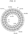
- a first connection 74a connecting the artificial blood vessel body 70 and the simulated ascending aorta 42b includes a first annular connection 76a, a first annular end 78a, a first non-woven fabric 80a, a first suture 82a, and a first sealing member 84a.
- the first annular connection 76a forms an end of the artificial blood vessel body 70.
- the first annular end 78a forms an end of the simulated ascending aorta 42b in the direction of arrow X1.
- the outer periphery of the first annular connection 76a is connected to the inner periphery of the first annular end 78a (inner periphery of the inner wall portion 50).
- the first non-woven fabric 80a is an annular mesh member and is located on the outer periphery of the first annular end 78a (outer periphery of the outer wall portion 52). In other words, in the first connection 74a, the first annular connection 76a, the first annular end 78a, and the first non-woven fabric 80a overlap each other sequentially and radially outward.
- the first non-woven fabric 80a elongates annularly around the outer periphery of the first annular end 78a.
- the first non-woven fabric 80a includes a soft plastic material. Examples of the soft plastic material included in the first non-woven fabric 80a include polyester and other fibers and silicone.
- the first annular connection 76a, the first annular end 78a, and the first non-woven fabric 80a overlapping each other are sewn with the first suture 82a.
- the first suture 82a is located at an end of the first annular end 78a closer to the first branched tube 72a (see Fig. 4 ).
- the first sealing member 84a includes, for example, a plastic material such as silicone.
- the first sealing member 84a covers the first non-woven fabric 80a thoroughly.
- the first sealing member 84a is filled into mesh patterns of the first non-woven fabric 80a.
- the first sealing member 84a covers an end surface of the first annular end 78a (see Fig. 4 ). Note that the first sealing member 84a does not cover the artificial blood vessel body 70 directly.
- a second connection 74b connecting the artificial blood vessel body 70 and the simulated descending aorta 42d includes a second annular connection 76b, a second annular end 78b, a second non-woven fabric 80b, a second suture 82b, and a second sealing member 84b.
- the second annular connection 76b forms an intermediate portion of the artificial blood vessel body 70.
- the second annular end 78b forms an end of the simulated descending aorta 42d in the direction of arrow X1.
- the outer periphery of the second annular connection 76b is connected to the inner periphery of the second annular end 78b (inner periphery of the inner wall portion 50).
- the second non-woven fabric 80b is an annular mesh member and is located on the outer periphery of the second annular end 78b (outer periphery of the outer wall portion 52). In other words, in the second connection 74b, the second annular connection 76b, the second annular end 78b, and the second non-woven fabric 80b overlap each other sequentially and radially outward.
- the second non-woven fabric 80b stretches annularly around the outer periphery of the second annular end 78b.
- the second non-woven fabric 80b includes a soft plastic material. Examples of the soft plastic material included in the second non-woven fabric 80b include polyester and other fibers and silicone.
- the second annular connection 76b, the second annular end 78b, and the second non-woven fabric 80b overlapping each other are sewn with the second suture 82b.
- the second suture 82b is located at an end of the second annular end 78b closer to the third branched tube 72c (see Fig. 4 ).
- the second sealing member 84b includes, for example, a plastic material such as silicone.
- the second sealing member 84b covers the second non-woven fabric 80b thoroughly.
- the second sealing member 84b is filled into mesh patterns of the second non-woven fabric 80b.
- the second sealing member 84b covers an end surface of the second annular end 78b (see Fig. 4 ).
- a first tube 86a is connected to an extending end of the first branched tube 72a in a liquid-tight manner.
- the first tube 86a is provided with a first lock 88a detachably attached to a desired position in the third side wall 28c of the tank 18.
- the first lock 88a has a sucker that sticks to the inner surface of the third side wall 28c.
- a second tube 86b is connected to an extending end of the second branched tube 72b in a liquid-tight manner.
- the second tube 86b is provided with a second lock 88b detachably attached to a desired position in the third side wall 28c of the tank 18.
- the second lock 88b includes a sucker that sticks to the inner surface of the third side wall 28c.
- An extending end of a third branched tube 72c has an opening communicating with the inside of the tank 18.
- This aorta model 38 is manufactured in the following manner. First, 3D data of the thoracic aorta and the abdominal aorta of a patient (data including a thoracic aorta aneurysm and Stanford type B aortic dissection) is created from clinical data (such as DICOM data). Based on the 3D data, a 3D-printed blood vessel mold is created. Then, first silicone is applied to the blood vessel mold to form the inner wall portion 50. Specifically, the blood vessel mold is immersed (dipped) in the first silicone. Accordingly, the inner wall portion 50 of the simulated vessel 42 is formed.
- second silicone is applied to the outer surface of the inner wall portion 50 to form the outer wall portion 52.
- the blood vessel mold provided with the inner wall portion 50 is immersed (dipped) in the second silicone. Accordingly, the outer wall portion 52 of the simulated vessel 42 is formed.
- the blood vessel mold is dissolved and removed from the inner side of the inner wall portion 50.
- a simulated vessel simulating the thoracic aorta and the abdominal aorta of a patient is formed in this manner, and a part of the simulated vessel that corresponds to the aortic arch of a human body is replaced with the artificial blood vessel 48, or a medical device.
- the aorta model 38 including the simulated vessel 42 and the artificial blood vessel 48 is provided.
- the aorta model 38 corresponds to an actual blood vessel having a deficient part which is replaced by the artificial blood vessel 48, or a therapeutic device.
- the femoral artery model 40 is disposed on the operating table 12, being adjacent to the fourth side wall 28d of the tank 18 in the direction of arrow X2.
- the femoral artery model 40 includes a simulated femoral artery 90 and a block 92 embedded with the simulated femoral artery 90.
- the simulated femoral artery 90 is, for example, a tube member molded in an integrated manner using a plastic material such as silicone.
- the simulated femoral artery 90 has transparency.
- the simulated femoral artery 90 includes a coupling tube 94, a simulated left femoral artery 96L, a simulated right femoral artery 96R, a left connecting channel 97L, and a right connecting channel 97R.
- One end of the coupling tube 94 is exposed from the block 92 and coupled to the fifth tube connector 30e.
- a lumen of the coupling tube 94 communicates with a lumen of the simulated abdominal aorta 42e through the fifth tube connector 30e.
- the simulated left femoral artery 96L and the simulated right femoral artery 96R branch and extend from the other end of the coupling tube 94.
- one end of the simulated left femoral artery 96L is connected to the other end of the coupling tube 94.
- One end of the simulated right femoral artery 96R is connected to the other end of the coupling tube 94.
- Other ends of the simulated left femoral artery 96L and the simulated right femoral artery 96R are exposed from the block 92.
- the other end of the simulated left femoral artery 96L is provided with a check valve 98 into which a medical device 200 is inserted (see Fig. 7 ).
- the check valve 98 prevents water leakage from the simulated left femoral artery 96L.
- the left connecting channel 97L branches from a side of the simulated left femoral artery 96L closer to the coupling tube 94 than the check valve 98 and is connected to the third connecting tube 36c.
- the other end of the simulated right femoral artery 96R may be closed or may be provided with a check valve as in the simulated left femoral artery 96L.
- the right connecting channel 97R branches from a side of the simulated right femoral artery 96R closer to the coupling tube 94 and is connected to the fourth connecting tube 36d.
- the block 92 has a cuboid shape.
- the block 92 includes a hard plastic material.
- the block 92 prevents the simulated femoral artery 90 from being elastically deformed radially outward. Accordingly, pressure (arterial pressure) from the pump 20 hardly escapes from the simulated femoral artery 90, and the aorta model 38 pulsates like the actual human aorta.
- An example of the hard plastic material included in the block 92 includes silicone.
- the block 92 has transparency. For this reason, from outside the block 92, a user can visually check the medical device 200 inserted into a lumen of an artery model body. Furthermore, surrounding the simulated femoral artery 90 with the block 92 enhances the durability of the simulated femoral artery 90.
- the radiography device 16 includes a radiography device body 100 disposed on the operating table 12 in the direction of arrow X1 and a display 102 that shows images captured by the radiography device body 100.
- the radiography device body 100 includes a base 104 installed on the floor 300, an arm 106 having a C-shape and rotatable relative to the base 104, a radiation source 108 located at one end of the arm 106, and a detector 110 located at the other end of the arm 106.
- the radiation source 108 irradiates a subject.
- the detector 110 detects the radiation penetrating the subject.
- the radiography device body 100 includes a controller (not illustrated) which creates a radiographic image based on the radiation detected by the detector 110 and causes the display 102 to show the image.
- the display 102 includes, for example, liquid crystal or organic EL.
- This embodiment describes a surgical training in which Stanford type B aortic dissection occurred in the descending aorta after replacing at least a part of the aortic arch with an artificial blood vessel (elephant trunk) is treated by Thoracic Endovascular Aortic Repair.
- the surgical simulator 10 is not limited to such a surgical training.
- the surgical simulator 10 may be applied to any surgical training as long as it is for retreatment of the descending aorta after at least a part of the aortic arch is replaced with an artificial blood vessel (elephant trunk).
- the simulation method involves, as illustrated in Fig. 6 , a preparation step, a setting step, a water supplying step, a guiding step, a radiography step, an expanding step, and a removing step.
- the blood vessel model 24 is prepared.
- a user sets the blood vessel model 24 as illustrated in Fig. 2 .
- the user submerges the aorta model 38 in the tank 18.
- the user places the aorta model 38 in a position shifted in the direction of arrow Y1 from the center of the tank 18 in Y direction.
- the user adjusts locking positions of the first lock 88a and the second lock 88b relative to the third side wall 28c of the tank 18 so as to deploy the aorta model 38 at a desired position and in a desired posture.
- the user supplies water into the blood vessel model 24.
- the user drives the pump 20.
- the pump 20 suctions water stored in the tank 18 through the first connecting tube 36a and discharges into the second connecting tube 36b.
- the water discharged into the second connecting tube 36b is guided to the artificial blood vessel body 70 through the guiding tube 54, the simulated coronary artery 42c, the simulated aortic root 42a, and the simulated ascending aorta 42b.
- the water guided into the artificial blood vessel body 70 diverts into the third branched tube 72c and the simulated descending aorta 42d.
- the water flowing into the third branched tube 72c is led into the tank 18.
- the water flowing into the simulated descending aorta 42d flows into the simulated abdominal aorta 42e and the coupling tube 94, and then, splits into the simulated left femoral artery 96L and the simulated right femoral artery 96R.
- the water flowing into the simulated left femoral artery 96L is returned to the tank 18 through the third connecting tube 36c.
- the water flowing into the simulated right femoral artery 96R is returned to the tank 18 through the fourth connecting tube 36d.
- the user guides the medical device 200 (a catheter 204 having the tip embedded with the stent graft 202) to a lesion of the simulated vessel 42 (dissected portion 58). Specifically, the user inserts the medical device 200 into the simulated left femoral artery 96L from the check valve 98. The user operates the catheter 204 to advance the tip of the catheter 204 (stent graft 202) from the simulated left femoral artery 96L to the simulated descending aorta 42d through the simulated abdominal aorta 42e. At this time, the user inserts the tip of the catheter 204 into a lumen of the artificial blood vessel 48.
- the user drives the radiography device 16 to capture an image of the medical device 200 inside the aorta model 38.
- the arm 106 is rotated (tilted) by a predetermined angle ⁇ relative to the base 104.
- the radiography device body 100 tilts the arm 106 so as to position the radiation source 108 closer to the second side wall 28b and to position the detector 110 closer to the first side wall 28a.
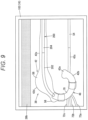
- the radiographic image shows the second side wall 28b (see Fig. 9 ).
- the aorta model 38 is separated from the second side wall 28b by the second interval L2, and the second side wall 28b in the radiographic image does not overlap the medical device 200. Accordingly, the medical device 200 can be checked visually in the radiographic image.
- Step S6 in Fig. 6 while the tip of the catheter 204 (stent graft 202) is placed in a position corresponding to the dissected portion 58 of the simulated descending aorta 42d, the user operates the catheter 204 to expand the stent graft 202.
- one end of the stent graft 202 is pressed against (brought into contact with) the inner surface of the other end of the artificial blood vessel 48.
- an intermediate portion and the other end of the stent graft 202 is pressed against the inner surface of the simulated vessel 42.
- the hole 64 in the partition wall 62 of the dissected portion 58 is closed by the stent graft 202.
- the user removes the catheter 204 from the blood vessel model 24.
- the stent graft 202 deployed may be removed from the blood vessel model 24 together with the catheter 204.
- the inner wall portion 50 of the simulated vessel 42 has elongation larger than that of the outer wall portion 52, which enables relatively smooth removal of the stent graft 202.
- the surgical simulator 10 and the simulation method according to this embodiment have the following effects.
- the blood vessel model 24 includes the aorta model 38 simulating a case of replacing a part of the thoracic aorta of a human body with an artificial blood vessel, and the aorta model 38 includes the simulated vessel 42 and the artificial blood vessel 48, or a medical device, connected to the simulated vessel 42.
- the aorta model 38 since the aorta model 38 includes the simulated vessel 42 and the artificial blood vessel 48, it is possible to simulate Thoracic Endovascular Aortic Repair for a complicated case of replacing a part of the thoracic aorta with an artificial blood vessel. Therefore, it is possible to learn Thoracic Endovascular Aortic Repair efficiently.
- the artificial blood vessel 48 of the aorta model 38 is placed in a part of the aorta model 38 corresponding to at least a part the aortic arch of a human body.
- the first connection 74a between the simulated vessel 42 and the artificial blood vessel 48 of the aorta model 38 includes the first annular end 78a that forms the simulated vessel 42 (simulated ascending aorta 42b) and the first annular connection 76a that forms the artificial blood vessel 48 of the aorta model 38.
- the first annular connection 76a is connected to the first annular end 78a in a liquid-tight manner while being inserted into a lumen of the first annular end 78a.
- the second connection 74b between the simulated vessel 42 and the artificial blood vessel 48 of the aorta model 38 includes the second annular end 78b that forms the simulated vessel 42 (simulated descending aorta 42d) and the second annular connection 76b that forms the artificial blood vessel 48 of the aorta model 38.
- the second annular connection 76b is connected to the second annular end 78b in a liquid-tight manner while being inserted into a lumen of the second annular end 78b.
- Such a configuration makes it possible to prevent the water in the aorta model 38 from leaking from the first connection 74a and the second connection 74b.
- the first connection 74a includes the soft plastic first non-woven fabric 80a located on the outer periphery of the first annular end 78a.
- the first annular connection 76a, the first annular end 78a, and the first non-woven fabric 80a overlapping each other are sewn with the first suture 82a.
- the second connection 74b includes the soft plastic second non-woven fabric 80b located on the outer periphery of the second annular end 78b.
- the second annular connection 76b, the second annular end 78b, and the second non-woven fabric 80b overlapping each other are sewn with the second suture 82b.
- the first connection 74a provided with the first non-woven fabric 80a prevents a tear in the simulated vessel 42 (first annular end 78a) when being sewn with the first suture 82a.
- the second connection 74b provided with the second non-woven fabric 80b also prevents tear in the simulated vessel 42 (second annular end 78b) when being sewn with the second suture 82b.
- the first connection 74a includes the plastic first sealing member 84a included in the first non-woven fabric 80a.
- the second connection 74b includes the plastic second sealing member 84b included in the second non-woven fabric 80b.
- Such a configuration further prevents the water in the aorta model 38 from leaking from the first connection 74a and the second connection 74b.
- the blood vessel model 24 includes the simulated femoral artery 90 mimicking the femoral artery of a human body and the block 92 embedded with the simulated femoral artery 90.
- the simulated vessel 42 and the simulated femoral artery 90 both include a soft plastic material, and the block 92 includes a hard plastic material.
- the block 92 prevents the arterial pressure from escaping from the simulated femoral artery 90. Accordingly, it is possible to pulsate the simulated vessel 42 like the actual thoracic aorta. Furthermore, it is possible to enhance the durability of the simulated femoral artery 90. Particularly, in a case where a simulated vessel composed of a plastic tube is used, the stent graft 202 is inserted into the tube unsmoothly and does not advance in the direction of insertion or causes the simulated vessel kinks. Embedding the simulated femoral artery 90 in a hard plastic enables smooth stent graft insertion into the simulated femoral artery 90.
- the surgical simulator 10 is provided with the tank 18 having a box shape configured to store water and house the aorta model 38 submerged in the water, the connection circuit 22 configured to cause the water in the tank 18 to circulate in the blood vessel model 24, and the pump 20 configured to apply arterial pressure to the water in the blood vessel model 24.
- Such a configuration pulsate the simulated vessel 42 efficiently. Furthermore, even if the water leaks from the connection (the first connection 74a or the second connection 74b) between the artificial blood vessel 48 and the simulated vessel 42, devices disposed outside the tank 18 (such as the operating table 12 and the radiography device 16) are prevented from getting wet.
- the tank 18 includes the bottom wall 26 and includes the first side wall 28a and the second side wall 28b protruding from the bottom wall 26 to face each other.
- the first interval L1 between the aorta model 38 and the first side wall 28a is shorter than the second interval L2 between the aorta model 38 and the second side wall 28b, and the second interval L2 is longer than the height H1 of the second side wall 28b
- the simulated vessel 42 includes the tubular inner wall portion 50 and the tubular outer wall portion 52 on the outer periphery of the inner wall portion 50.
- the inner wall portion 50 and the outer wall portion 52 each includes a soft plastic material, and the inner wall portion 50 has elongation larger than that of the outer wall portion 52.
- the inner wall portion 50 to which the medical device 200 comes into contact during Thoracic Endovascular Aortic Repair stretches in the longitudinal direction (direction of insertion of the medical device 200), and the stent graft 202 is prevented from being stacked in the inner wall portion 50 when inserting the medical device 200 (and even when removing the stent graft 202). Furthermore, when the stent graft 202 expands in diameter, the simulated vessel 42 is prevented from expanding excessively in the radial direction.
- the simulated vessel 42 includes the partition wall 62 configured to partition a lumen of the simulated vessel 42 into the true lumen 60a and the false lumen 60b, and the partition wall 62 is provided with the hole 64 that allows the true lumen 60a and the false lumen 60b to communicate with each other.
- Such a configuration enables reproduction of the dissected portion 58 in the simulated vessel 42.
- the simulation method using the surgical simulator 10 involves: the water supplying step for supplying water in the blood vessel model 24; the guiding step for operating the catheter 204 while the water flows in the blood vessel model 24 to guide the stent graft 202 embedded in the tip of the catheter 204 into the aorta model 38; and the expanding step for expanding the stent graft 202 after the guiding step.
- This simulation method has effects similar to those obtained by the surgical simulator 10.
- the present invention is not limited to the embodiment described above and may be modified in various manners without departing from the gist of the present invention.
- the embodiment discloses a surgical simulator (10) including a blood vessel model (24).
- the blood vessel model includes an aorta model (38) mimicking a case of replacing a part of the thoracic aorta of a human body with an artificial blood vessel.
- the aorta model includes a simulated vessel (42) and an artificial blood vessel (48), or a medical device, connected to the simulated vessel.
- the artificial blood vessel of the aorta model may be located in a part of the aorta model corresponding to at least a part of the aortic arch of a human body.
- the aorta model has a connection (74a and 74b) between the simulated vessel and the artificial blood vessel, and the connection may include an annular end (78a and 78b) that forms the simulated vessel and an annular connection (76a and 76b) that forms the artificial blood vessel of the aorta model.
- the annular connection may be connected to the annular end in a liquid-tight manner while being inserted into a lumen of the annular end.
- connection may include a non-woven fabric (80a and 80b) including a soft plastic and located on outer periphery of the annular end.
- the annular connection, the annular end, and the non-woven fabric may be sewn with a suture (82a and 82b) while overlapping each other.
- connection may include a plastic sealing member (84a and 84b) included in the non-woven fabric.
- the blood vessel model may include a simulated femoral artery (90) simulating the femoral artery of a human body and a block (92) embedded with the simulated femoral artery.
- the simulated vessel and the simulated femoral artery may both include a soft plastic material, and the block may include a hard plastic material.
- the surgical simulator may include a tank (18) having a box shape configured to store water and house the aorta model submerged in the water, a connection circuit (22) configured to cause the water in the tank to circulate in the blood vessel model, and a pump (20) configured to apply arterial pressure to the water in the blood vessel model.
- the tank may include a bottom wall (26) and include a first side wall (28a) and a second side wall (28b) protruding from the bottom wall to face each other.
- the aorta model may have a first interval (L1) between the first side wall.
- the first interval may be shorter than a second interval (L2) between the aorta model and the second side wall, and the second interval may be longer than a height (H1) of the second side wall.
- the simulated vessel may include a tubular inner wall portion (50) and a tubular outer wall portion (52) located on outer periphery of the inner wall portion.
- the inner wall portion and the outer wall portion may both include a soft plastic material, and the inner wall portion may have elongation larger than elongation of the outer wall portion.
- the simulated vessel may include a partition wall (62) configured to partition a lumen of the simulated vessel into a true lumen (60a) and a false lumen (60b), and the partition wall may be provided with a hole (64) that allows the true lumen and the false lumen to communicate with each other.
- the embodiment discloses a simulation method using the aforementioned surgical simulator, the method involving: a water supplying step for supplying water in the blood vessel model; a guiding step for operating a catheter (204) while the water flows in the blood vessel model to guide a stent graft (202) embedded in a tip of the catheter into the aorta model; and an expanding step for expanding the stent graft after the guiding step.
Landscapes
- Engineering & Computer Science (AREA)
- Physics & Mathematics (AREA)
- General Physics & Mathematics (AREA)
- Health & Medical Sciences (AREA)
- Business, Economics & Management (AREA)
- Theoretical Computer Science (AREA)
- Educational Administration (AREA)
- Educational Technology (AREA)
- General Health & Medical Sciences (AREA)
- Mathematical Analysis (AREA)
- Pure & Applied Mathematics (AREA)
- Chemical & Material Sciences (AREA)
- Mathematical Physics (AREA)
- Medical Informatics (AREA)
- Medicinal Chemistry (AREA)
- Algebra (AREA)
- Computational Mathematics (AREA)
- Mathematical Optimization (AREA)
- Radiology & Medical Imaging (AREA)
- Pulmonology (AREA)
- Nuclear Medicine, Radiotherapy & Molecular Imaging (AREA)
- Entrepreneurship & Innovation (AREA)
- Prostheses (AREA)
- Instructional Devices (AREA)
- Management, Administration, Business Operations System, And Electronic Commerce (AREA)
Abstract
Description
- The present invention relates to a surgical simulator and a simulation method.
- For example,
JP 2015-64487 A - In the treatment of thoracic aorta aneurysms, a thoracic aorta aneurysm may recur after an operation to replace a part of the thoracic aorta with an artificial blood vessel. In recent years, with the evolution of therapeutic devices, Thoracic Endovascular Aortic Repair has enabled percutaneous deployment of a stent graft in a lesion of the thoracic aorta (aneurysm portion or dissected portion) even in retreatment cases. Furthermore, in occurrence of Stanford type B aortic dissection in which a wall of the descending aorta is torn and divided into two lumens (a true lumen and a false lumen), a stent graft may be deployed in the descending aorta by Thoracic Endovascular Aortic Repair in the early phase. In this manner, with the progress of therapeutic devices, it has become possible to perform percutaneous treatment even in complicated cases, and at the same time, doctors are required to quickly learn how to operate leading-edge therapeutic devices.
- A surgical simulator disclosed in
JP 2015-64487 A JP 2015-64487 A - The invention has been made in light of the problems, and an object of the invention is to provide a surgical simulator and a simulation method that enable simulation of Thoracic Endovascular Aortic Repair for complicated thoracic aorta cases and enable efficient learning of Thoracic Endovascular Aortic Repair.
- An aspect of the invention is a surgical simulator including a blood vessel model, the blood vessel model including an aorta model mimicking a case of replacing a part of the thoracic aorta of a human body with an artificial blood vessel, and the aorta model including a simulated vessel and an artificial blood vessel, or a medical device, connected to the simulated vessel.
- Another aspect of the invention is a simulation method using the surgical simulator, the method involving: a water supplying step for supplying water in the blood vessel model; a guiding step for operating a catheter while the water flows in the blood vessel model to guide a stent graft embedded in a tip of the catheter into the aorta model; and an expanding step for expanding the stent graft after the guiding step.
- According to the invention, the aorta model includes the simulated vessel and the artificial blood vessel, which enables simulation of Thoracic Endovascular Aortic Repair for complicated thoracic aorta cases. Therefore, it is possible to learn Thoracic Endovascular Aortic Repair efficiently.
-
-
Fig. 1 is a front view of a surgical simulator according to an embodiment of the invention. -
Fig. 2 is a plan view of a simulator body illustrated inFig. 1 . -
Fig. 3 is a partially omitted longitudinal sectional view of an aorta model illustrated inFig. 2 . -
Fig. 4 is a partially enlarged longitudinal sectional view of the aorta model illustrated inFig. 3 . -
Fig. 5 is a transverse cross-sectional view of a first connection (second connection) illustrated inFig. 3 . -
Fig. 6 is a flowchart for describing a simulation method using the surgical simulator ofFig. 1 . -
Fig. 7 is a view for describing a water supplying step and a guiding step. -
Fig. 8 is a view for describing a radiography step. -
Fig. 9 is a view for describing a radiographic image captured in the radiography step. -
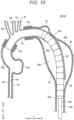
Fig. 10 is a view for describing a simulation method using the surgical simulator according to an embodiment of the invention. - A preferred embodiment of a surgical simulator and a simulation method according to the invention will now be described with reference to the accompanying drawings.
- A
surgical simulator 10 according to an embodiment of the invention is used for training in Thoracic Endovascular Aortic Repair of the thoracic aorta. - As illustrated in
Fig. 1 , thesurgical simulator 10 includes an operating table 12 installed on afloor 300, asimulator body 14 located on the operating table 12, and aradiography device 16 installed on thefloor 300. The operating table 12 extends in one direction (direction of arrow X). The operating table 12 can move up and down in the height direction (direction of arrow Z). - As illustrated in
Figs. 1 and2 , thesimulator body 14 includes atank 18, apump 20, aconnection circuit 22, and ablood vessel model 24. Thetank 18 can be comprised, for example, polyvinyl chloride (PVC). Thetank 18 is disposed at one end of the operating table 12 in the longitudinal direction (direction of arrow X1). - In
Fig. 2 , thetank 18 is located substantially at the center of the operating table 12 in the transverse direction (width direction, direction of arrow Y). Thetank 18 can have a box shape with an open top. Thetank 18 is formed of a transparent plastic. Thetank 18 includes a quadrangular bottom wall 26 (seeFig. 2 ) and first tofourth side walls 28a to 28d protruding in the height direction (direction of arrow Z) from each side of thebottom wall 26. - The
first side wall 28a is located at an end of thebottom wall 26 in a direction of arrow Y1 (one side of the operating table 12 in the transverse direction). Thesecond side wall 28b is located at an end of thebottom wall 26 in a direction of arrow Y2 (the other side of the operating table 12 in the transverse direction). Thethird side wall 28c is located at an end of thebottom wall 26 in the direction of arrow X1. Thefourth side wall 28d is located at an end of thebottom wall 26 in a direction of arrow X2 (opposite to the direction of arrow X1). - The
fourth side wall 28d is provided with afirst tube connector 30a, asecond tube connector 30b, athird tube connector 30c, afourth tube connector 30d, and afifth tube connector 30e. The material, shape, and size of thetank 18 are designed appropriately. - The
pump 20 is used for suctioning water in thetank 18 and supplying the water to theblood vessel model 24. Thepump 20 supplies the water to theblood vessel model 24 in such a manner that pressure comparable to arterial pressure is applied to theblood vessel model 24. Thepump 20 includes asuction port 32 for suctioning the water and adischarge port 34 for discharging the water. - The
connection circuit 22 is used for circulating the water in thetank 18 through theblood vessel model 24. Theconnection circuit 22 includes afirst connecting tube 36a, a second connectingtube 36b, a third connectingtube 36c, and a fourth connectingtube 36d. The first connectingtube 36a forms a channel for guiding the water in thetank 18 to thepump 20. The first connectingtube 36a connects thefirst tube connector 30a and thesuction port 32 of thepump 20. A lumen of the first connectingtube 36a communicates with thetank 18 through thefirst tube connector 30a. The second connectingtube 36b forms a channel for guiding the water discharged from thepump 20 into theblood vessel model 24. The second connectingtube 36b connects thedischarge port 34 of thepump 20 and thesecond tube connector 30b. - The third connecting
tube 36c and the fourth connectingtube 36d each form a channel for returning the water supplied to theblood vessel model 24 to thetank 18. The third connectingtube 36c connects thethird tube connector 30c and a simulatedfemoral artery 90. The fourth connectingtube 36d connects thefourth tube connector 30d and the simulatedfemoral artery 90. - The
blood vessel model 24 includes anaorta model 38 submerged in thetank 18 and afemoral artery model 40 disposed outside thetank 18. - As illustrated in
Figs. 2 and3 , theaorta model 38 simulates a case of replacing a part of the thoracic aorta of a human body with an artificial blood vessel. Theaorta model 38 includes a simulatedvessel 42 and anartificial blood vessel 48, or a medical device, connected to the simulatedvessel 42. In this embodiment, theartificial blood vessel 48 is located in a part of theaorta model 38 corresponding to the aortic arch of a human body. - In
Fig. 8 , a first interval L1 between theaorta model 38 and thefirst side wall 28a is shorter than a second interval L2 between theaorta model 38 and thesecond side wall 28b. The second interval L2 is longer than a height H1 of thesecond side wall 28b (a length from thebottom wall 26 to a protruding end of thesecond side wall 28b). Theaorta model 38 is adjacent to thefirst side wall 28a. In other words, theaorta model 38 is placed in a position closer to thefirst side wall 28a (direction of arrow Y1) relative to the center of thetank 18 in the direction of arrow Y. - As illustrated in
Fig. 3 , thesimulated vessel 42 includes a tubularinner wall portion 50 and a tubularouter wall portion 52 on the outer periphery of theinner wall portion 50. Theinner wall portion 50 and theouter wall portion 52 both include silicone. Theinner wall portion 50 has a thickness smaller than that of theouter wall portion 52. Specifically, theinner wall portion 50 preferably has a thickness of 0.2 mm or more and 0.7 mm or less, more preferably 0.3 mm or more and 0.6 mm or less, and still more preferably about 0.5 mm. Theouter wall portion 52 preferably has a thickness of 1.3 mm or more and 2.5 mm or less, more preferably 1.5 mm or more and 2.2 mm or less, and still more preferably about 2.0 mm. Thicknesses of theinner wall portion 50 and theouter wall portion 52 are designed appropriately. - The
inner wall portion 50 has elongation larger than that of theouter wall portion 52. Specifically, theinner wall portion 50 preferably has elongation of 500% or more and 700% or less, more preferably 550% or more and 650% or less, still more preferably about 600%. Theouter wall portion 52 preferably has elongation of 200% or more and 400% or less, more preferably 250% or more and 350% or less, and still more preferably about 300%. Elongation of each of theinner wall portion 50 and theouter wall portion 52 is designed appropriately. - The
inner wall portion 50 has a tear strength larger than the tear strength of theouter wall portion 52. Specifically, theinner wall portion 50 preferably has a tear strength of 30 kgf or more and 40 kgf or less, and more preferably about 36 kgf. Theouter wall portion 52 preferably has a tear strength of 10 kgf or more and 20 kgf or less, and more preferably about 17 kgf. - A surfactant is applied to the inner surface of the
inner wall portion 50. Accordingly, when inserting astent graft 202 which is folded (seeFig. 7 ), it is possible to prevent thestent graft 202 from being stuck in the inner surface of theinner wall portion 50. - The
simulated vessel 42 includes a simulatedaortic root 42a, asimulated ascending aorta 42b, a simulatedcoronary artery 42c, asimulated descending aorta 42d, and a simulatedabdominal aorta 42e. The simulatedaortic root 42a simulates the aortic root of a human body. Thesimulated ascending aorta 42b simulates the ascending aorta of a human body. Thesimulated ascending aorta 42b extends from the simulatedaortic root 42a in the direction of arrow X1. An elongated end of thesimulated ascending aorta 42b (end in the direction of arrow X1) is connected to theartificial blood vessel 48. The simulatedabdominal aorta 42e simulates the abdominal aorta of a human body. - The simulated
coronary artery 42c simulates the coronary artery of a human body. The simulatedcoronary artery 42c extends from the simulatedaortic root 42a in the direction of arrow X2. InFig. 2 , a guidingtube 54 is connected to an elongated end of the simulatedcoronary artery 42c in a liquid-tight manner. The guidingtube 54 is connected to thesecond tube connector 30b located in thefourth side wall 28d of thetank 18. In other words, a lumen of the guidingtube 54 communicates with a lumen of the second connectingtube 36b through thesecond tube connector 30b. - As illustrated in
Fig. 3 , thesimulated descending aorta 42d simulates the descending aorta, a part of the aortic arch, of a human body. Thesimulated descending aorta 42d extends in the direction of arrow X. An end of thesimulated descending aorta 42d in the direction of arrow X1 is connected to theartificial blood vessel 48. - In
Fig. 2 , the simulatedabdominal aorta 42e extends from thesimulated descending aorta 42d in the direction of arrow X2. An extending end of the simulatedabdominal aorta 42e is coupled to thefifth tube connector 30e located in thefourth side wall 28d of thetank 18. - The
simulated vessel 42 is provided with ananeurysm portion 56 and a dissectedportion 58. Theaneurysm portion 56 is located at an end of thesimulated descending aorta 42d in the direction of arrow X1. The dissectedportion 58 is located in an intermediate portion of thesimulated descending aorta 42d. The dissectedportion 58 simulates what is called Stanford type B aortic dissection. The dissectedportion 58 includes apartition wall 62 that partitions a lumen of thesimulated descending aorta 42d into atrue lumen 60a and afalse lumen 60b. Thepartition wall 62 is provided with ahole 64 that allows thetrue lumen 60a and thefalse lumen 60b to communicate with each other. - In
Fig. 3 , theartificial blood vessel 48 is connected to thesimulated vessel 42 and forms theblood vessel model 24 corresponding to a case of what is called an elephant trunk. Theartificial blood vessel 48 includes, for example, polyethylene terephthalate (PET), polyurethane, polytetrafluoroethylene (PTFE). Theartificial blood vessel 48 includes an artificialblood vessel body 70 that connects thesimulated ascending aorta 42b and thesimulated descending aorta 42d and includes a firstbranched tube 72a, a secondbranched tube 72b, and a thirdbranched tube 72c that extend from the artificialblood vessel body 70 in the direction of arrow X1. - As illustrated in
Figs. 4 and5 , afirst connection 74a connecting the artificialblood vessel body 70 and thesimulated ascending aorta 42b includes a firstannular connection 76a, a firstannular end 78a, a firstnon-woven fabric 80a, afirst suture 82a, and afirst sealing member 84a. The firstannular connection 76a forms an end of the artificialblood vessel body 70. The firstannular end 78a forms an end of thesimulated ascending aorta 42b in the direction of arrow X1. The outer periphery of the firstannular connection 76a is connected to the inner periphery of the firstannular end 78a (inner periphery of the inner wall portion 50). - The first
non-woven fabric 80a is an annular mesh member and is located on the outer periphery of the firstannular end 78a (outer periphery of the outer wall portion 52). In other words, in thefirst connection 74a, the firstannular connection 76a, the firstannular end 78a, and the firstnon-woven fabric 80a overlap each other sequentially and radially outward. The firstnon-woven fabric 80a elongates annularly around the outer periphery of the firstannular end 78a. The firstnon-woven fabric 80a includes a soft plastic material. Examples of the soft plastic material included in the firstnon-woven fabric 80a include polyester and other fibers and silicone. - The first
annular connection 76a, the firstannular end 78a, and the firstnon-woven fabric 80a overlapping each other are sewn with thefirst suture 82a. Thefirst suture 82a is located at an end of the firstannular end 78a closer to the firstbranched tube 72a (seeFig. 4 ). Thefirst sealing member 84a includes, for example, a plastic material such as silicone. Thefirst sealing member 84a covers the firstnon-woven fabric 80a thoroughly. Thefirst sealing member 84a is filled into mesh patterns of the firstnon-woven fabric 80a. Thefirst sealing member 84a covers an end surface of the firstannular end 78a (seeFig. 4 ). Note that thefirst sealing member 84a does not cover the artificialblood vessel body 70 directly. - A
second connection 74b connecting the artificialblood vessel body 70 and thesimulated descending aorta 42d includes a secondannular connection 76b, a secondannular end 78b, a secondnon-woven fabric 80b, asecond suture 82b, and asecond sealing member 84b. The secondannular connection 76b forms an intermediate portion of the artificialblood vessel body 70. The secondannular end 78b forms an end of thesimulated descending aorta 42d in the direction of arrow X1. The outer periphery of the secondannular connection 76b is connected to the inner periphery of the secondannular end 78b (inner periphery of the inner wall portion 50). - The second
non-woven fabric 80b is an annular mesh member and is located on the outer periphery of the secondannular end 78b (outer periphery of the outer wall portion 52). In other words, in thesecond connection 74b, the secondannular connection 76b, the secondannular end 78b, and the secondnon-woven fabric 80b overlap each other sequentially and radially outward. The secondnon-woven fabric 80b stretches annularly around the outer periphery of the secondannular end 78b. The secondnon-woven fabric 80b includes a soft plastic material. Examples of the soft plastic material included in the secondnon-woven fabric 80b include polyester and other fibers and silicone. - The second
annular connection 76b, the secondannular end 78b, and the secondnon-woven fabric 80b overlapping each other are sewn with thesecond suture 82b. Thesecond suture 82b is located at an end of the secondannular end 78b closer to the thirdbranched tube 72c (seeFig. 4 ). Thesecond sealing member 84b includes, for example, a plastic material such as silicone. Thesecond sealing member 84b covers the secondnon-woven fabric 80b thoroughly. Thesecond sealing member 84b is filled into mesh patterns of the secondnon-woven fabric 80b. Thesecond sealing member 84b covers an end surface of the secondannular end 78b (seeFig. 4 ). - As illustrated in
Fig. 3 , the other end of the artificialblood vessel body 70 is inserted into the lumen of thesimulated descending aorta 42d to cover theaneurysm portion 56 from inside. InFig. 2 , afirst tube 86a is connected to an extending end of the firstbranched tube 72a in a liquid-tight manner. Thefirst tube 86a is provided with afirst lock 88a detachably attached to a desired position in thethird side wall 28c of thetank 18. Thefirst lock 88a has a sucker that sticks to the inner surface of thethird side wall 28c. - A
second tube 86b is connected to an extending end of the secondbranched tube 72b in a liquid-tight manner. Thesecond tube 86b is provided with asecond lock 88b detachably attached to a desired position in thethird side wall 28c of thetank 18. Thesecond lock 88b includes a sucker that sticks to the inner surface of thethird side wall 28c. An extending end of a thirdbranched tube 72c has an opening communicating with the inside of thetank 18. - This
aorta model 38 is manufactured in the following manner. First, 3D data of the thoracic aorta and the abdominal aorta of a patient (data including a thoracic aorta aneurysm and Stanford type B aortic dissection) is created from clinical data (such as DICOM data). Based on the 3D data, a 3D-printed blood vessel mold is created. Then, first silicone is applied to the blood vessel mold to form theinner wall portion 50. Specifically, the blood vessel mold is immersed (dipped) in the first silicone. Accordingly, theinner wall portion 50 of thesimulated vessel 42 is formed. - Next, second silicone is applied to the outer surface of the
inner wall portion 50 to form theouter wall portion 52. Specifically, the blood vessel mold provided with theinner wall portion 50 is immersed (dipped) in the second silicone. Accordingly, theouter wall portion 52 of thesimulated vessel 42 is formed. After that, the blood vessel mold is dissolved and removed from the inner side of theinner wall portion 50. A simulated vessel simulating the thoracic aorta and the abdominal aorta of a patient is formed in this manner, and a part of the simulated vessel that corresponds to the aortic arch of a human body is replaced with theartificial blood vessel 48, or a medical device. Through these processes, there is provided theaorta model 38 including thesimulated vessel 42 and theartificial blood vessel 48. In other words, theaorta model 38 corresponds to an actual blood vessel having a deficient part which is replaced by theartificial blood vessel 48, or a therapeutic device. - In
Figs. 1 and2 , thefemoral artery model 40 is disposed on the operating table 12, being adjacent to thefourth side wall 28d of thetank 18 in the direction of arrow X2. Thefemoral artery model 40 includes a simulatedfemoral artery 90 and ablock 92 embedded with the simulatedfemoral artery 90. - The simulated
femoral artery 90 is, for example, a tube member molded in an integrated manner using a plastic material such as silicone. The simulatedfemoral artery 90 has transparency. The simulatedfemoral artery 90 includes acoupling tube 94, a simulated leftfemoral artery 96L, a simulated rightfemoral artery 96R, aleft connecting channel 97L, and aright connecting channel 97R. - One end of the
coupling tube 94 is exposed from theblock 92 and coupled to thefifth tube connector 30e. In other words, a lumen of thecoupling tube 94 communicates with a lumen of the simulatedabdominal aorta 42e through thefifth tube connector 30e. The simulated leftfemoral artery 96L and the simulated rightfemoral artery 96R branch and extend from the other end of thecoupling tube 94. In other words, one end of the simulated leftfemoral artery 96L is connected to the other end of thecoupling tube 94. One end of the simulated rightfemoral artery 96R is connected to the other end of thecoupling tube 94. Other ends of the simulated leftfemoral artery 96L and the simulated rightfemoral artery 96R are exposed from theblock 92. - The other end of the simulated left
femoral artery 96L is provided with acheck valve 98 into which amedical device 200 is inserted (seeFig. 7 ). Thecheck valve 98 prevents water leakage from the simulated leftfemoral artery 96L. Theleft connecting channel 97L branches from a side of the simulated leftfemoral artery 96L closer to thecoupling tube 94 than thecheck valve 98 and is connected to the third connectingtube 36c. The other end of the simulated rightfemoral artery 96R may be closed or may be provided with a check valve as in the simulated leftfemoral artery 96L. Theright connecting channel 97R branches from a side of the simulated rightfemoral artery 96R closer to thecoupling tube 94 and is connected to the fourth connectingtube 36d. - The
block 92 has a cuboid shape. Theblock 92 includes a hard plastic material. In other words, theblock 92 prevents the simulatedfemoral artery 90 from being elastically deformed radially outward. Accordingly, pressure (arterial pressure) from thepump 20 hardly escapes from the simulatedfemoral artery 90, and theaorta model 38 pulsates like the actual human aorta. An example of the hard plastic material included in theblock 92 includes silicone. Theblock 92 has transparency. For this reason, from outside theblock 92, a user can visually check themedical device 200 inserted into a lumen of an artery model body. Furthermore, surrounding the simulatedfemoral artery 90 with theblock 92 enhances the durability of the simulatedfemoral artery 90. - As illustrated in
Fig. 1 , theradiography device 16 includes aradiography device body 100 disposed on the operating table 12 in the direction of arrow X1 and adisplay 102 that shows images captured by theradiography device body 100. Theradiography device body 100 includes a base 104 installed on thefloor 300, anarm 106 having a C-shape and rotatable relative to thebase 104, aradiation source 108 located at one end of thearm 106, and adetector 110 located at the other end of thearm 106. - The
radiation source 108 irradiates a subject. Thedetector 110 detects the radiation penetrating the subject. Theradiography device body 100 includes a controller (not illustrated) which creates a radiographic image based on the radiation detected by thedetector 110 and causes thedisplay 102 to show the image. Thedisplay 102 includes, for example, liquid crystal or organic EL. - Hereinafter described is a simulation method using the
surgical simulator 10 according to this embodiment. This embodiment describes a surgical training in which Stanford type B aortic dissection occurred in the descending aorta after replacing at least a part of the aortic arch with an artificial blood vessel (elephant trunk) is treated by Thoracic Endovascular Aortic Repair. However, thesurgical simulator 10 is not limited to such a surgical training. Thesurgical simulator 10 may be applied to any surgical training as long as it is for retreatment of the descending aorta after at least a part of the aortic arch is replaced with an artificial blood vessel (elephant trunk). - The simulation method according to this embodiment involves, as illustrated in
Fig. 6 , a preparation step, a setting step, a water supplying step, a guiding step, a radiography step, an expanding step, and a removing step. - First, in the preparation step (Step S1), the
blood vessel model 24 is prepared. In the setting step (Step S2), a user sets theblood vessel model 24 as illustrated inFig. 2 . Specifically, in the setting step, the user submerges theaorta model 38 in thetank 18. Herein, the user places theaorta model 38 in a position shifted in the direction of arrow Y1 from the center of thetank 18 in Y direction. Furthermore, the user adjusts locking positions of thefirst lock 88a and thesecond lock 88b relative to thethird side wall 28c of thetank 18 so as to deploy theaorta model 38 at a desired position and in a desired posture. - Next, in the water supplying step (Step S3), the user supplies water into the
blood vessel model 24. Specifically, in the water supplying step, the user drives thepump 20. Accordingly, as illustrated inFig. 7 , thepump 20 suctions water stored in thetank 18 through the first connectingtube 36a and discharges into the second connectingtube 36b. The water discharged into the second connectingtube 36b is guided to the artificialblood vessel body 70 through the guidingtube 54, the simulatedcoronary artery 42c, the simulatedaortic root 42a, and thesimulated ascending aorta 42b. The water guided into the artificialblood vessel body 70 diverts into the thirdbranched tube 72c and thesimulated descending aorta 42d. The water flowing into the thirdbranched tube 72c is led into thetank 18. The water flowing into thesimulated descending aorta 42d flows into the simulatedabdominal aorta 42e and thecoupling tube 94, and then, splits into the simulated leftfemoral artery 96L and the simulated rightfemoral artery 96R. The water flowing into the simulated leftfemoral artery 96L is returned to thetank 18 through the third connectingtube 36c. The water flowing into the simulated rightfemoral artery 96R is returned to thetank 18 through the fourth connectingtube 36d. - After that, in the guiding step (Step S4 in
Fig. 6 ), the user guides the medical device 200 (acatheter 204 having the tip embedded with the stent graft 202) to a lesion of the simulated vessel 42 (dissected portion 58). Specifically, the user inserts themedical device 200 into the simulated leftfemoral artery 96L from thecheck valve 98. The user operates thecatheter 204 to advance the tip of the catheter 204 (stent graft 202) from the simulated leftfemoral artery 96L to thesimulated descending aorta 42d through the simulatedabdominal aorta 42e. At this time, the user inserts the tip of thecatheter 204 into a lumen of theartificial blood vessel 48. - Furthermore, in the radiography step (Step S5), the user drives the
radiography device 16 to capture an image of themedical device 200 inside theaorta model 38. At this time, as illustrated inFig. 8 , thearm 106 is rotated (tilted) by a predetermined angle θ relative to thebase 104. Specifically, theradiography device body 100 tilts thearm 106 so as to position theradiation source 108 closer to thesecond side wall 28b and to position thedetector 110 closer to thefirst side wall 28a. In this case, the radiographic image shows thesecond side wall 28b (seeFig. 9 ). However, theaorta model 38 is separated from thesecond side wall 28b by the second interval L2, and thesecond side wall 28b in the radiographic image does not overlap themedical device 200. Accordingly, themedical device 200 can be checked visually in the radiographic image. - Next, in the expanding step (Step S6 in
Fig. 6 ), while the tip of the catheter 204 (stent graft 202) is placed in a position corresponding to the dissectedportion 58 of thesimulated descending aorta 42d, the user operates thecatheter 204 to expand thestent graft 202. This makes thestent graft 202 expand in diameter as illustrated inFig. 10 . Accordingly, one end of thestent graft 202 is pressed against (brought into contact with) the inner surface of the other end of theartificial blood vessel 48. In addition, an intermediate portion and the other end of thestent graft 202 is pressed against the inner surface of thesimulated vessel 42. In other words, thehole 64 in thepartition wall 62 of the dissectedportion 58 is closed by thestent graft 202. - After that, in the removing step (Step S7 in
Fig. 6 ), the user removes thecatheter 204 from theblood vessel model 24. In this removing step, note that thestent graft 202 deployed may be removed from theblood vessel model 24 together with thecatheter 204. In this case, although thestent graft 202 expands in diameter, theinner wall portion 50 of thesimulated vessel 42 has elongation larger than that of theouter wall portion 52, which enables relatively smooth removal of thestent graft 202. After the removing step, the simulation using thesurgical simulator 10 is complete. - The
surgical simulator 10 and the simulation method according to this embodiment have the following effects. - In the
surgical simulator 10, theblood vessel model 24 includes theaorta model 38 simulating a case of replacing a part of the thoracic aorta of a human body with an artificial blood vessel, and theaorta model 38 includes thesimulated vessel 42 and theartificial blood vessel 48, or a medical device, connected to thesimulated vessel 42. - According to this configuration, since the
aorta model 38 includes thesimulated vessel 42 and theartificial blood vessel 48, it is possible to simulate Thoracic Endovascular Aortic Repair for a complicated case of replacing a part of the thoracic aorta with an artificial blood vessel. Therefore, it is possible to learn Thoracic Endovascular Aortic Repair efficiently. - The
artificial blood vessel 48 of theaorta model 38 is placed in a part of theaorta model 38 corresponding to at least a part the aortic arch of a human body. - With this configuration, it is possible to simulate Thoracic Endovascular Aortic Repair for a case of replacing at least a part of the aortic arch with an artificial blood vessel. In addition, at least a part of the outside of the
artificial blood vessel 48 is not provided with theaorta model 38, and the wall of the plastic blood vessel does not disturb a feeling of inserting thestent graft 202 into theartificial blood vessel 48, which makes it possible to simulate a feeling of the actual thoracic aorta being stretched during Thoracic Endovascular Aortic Repair. - The
first connection 74a between thesimulated vessel 42 and theartificial blood vessel 48 of theaorta model 38 includes the firstannular end 78a that forms the simulated vessel 42 (simulated ascendingaorta 42b) and the firstannular connection 76a that forms theartificial blood vessel 48 of theaorta model 38. The firstannular connection 76a is connected to the firstannular end 78a in a liquid-tight manner while being inserted into a lumen of the firstannular end 78a. Furthermore, thesecond connection 74b between thesimulated vessel 42 and theartificial blood vessel 48 of theaorta model 38 includes the secondannular end 78b that forms the simulated vessel 42 (simulated descendingaorta 42d) and the secondannular connection 76b that forms theartificial blood vessel 48 of theaorta model 38. The secondannular connection 76b is connected to the secondannular end 78b in a liquid-tight manner while being inserted into a lumen of the secondannular end 78b. - Such a configuration makes it possible to prevent the water in the
aorta model 38 from leaking from thefirst connection 74a and thesecond connection 74b. - The
first connection 74a includes the soft plastic firstnon-woven fabric 80a located on the outer periphery of the firstannular end 78a. The firstannular connection 76a, the firstannular end 78a, and the firstnon-woven fabric 80a overlapping each other are sewn with thefirst suture 82a. Thesecond connection 74b includes the soft plastic secondnon-woven fabric 80b located on the outer periphery of the secondannular end 78b. The secondannular connection 76b, the secondannular end 78b, and the secondnon-woven fabric 80b overlapping each other are sewn with thesecond suture 82b. - With this configuration, it is possible to approximate softness of the
first connection 74a and thesecond connection 74b to that of a connection between the actual thoracic aorta and theartificial blood vessel 48. What is more, while maintaining the strength, it is possible to connect the plasticsimulated vessel 42 and theartificial blood vessel 48 which normally cannot adhere to each other. Accordingly, even when arterial pressure is applied to the water in theaorta model 38, theartificial blood vessel 48 is efficiently prevented from slipping from thesimulated vessel 42. In addition, thefirst connection 74a provided with the firstnon-woven fabric 80a prevents a tear in the simulated vessel 42 (firstannular end 78a) when being sewn with thefirst suture 82a. Thesecond connection 74b provided with the secondnon-woven fabric 80b also prevents tear in the simulated vessel 42 (secondannular end 78b) when being sewn with thesecond suture 82b. - The
first connection 74a includes the plasticfirst sealing member 84a included in the firstnon-woven fabric 80a. Thesecond connection 74b includes the plasticsecond sealing member 84b included in the secondnon-woven fabric 80b. - Such a configuration further prevents the water in the
aorta model 38 from leaking from thefirst connection 74a and thesecond connection 74b. - The
blood vessel model 24 includes the simulatedfemoral artery 90 mimicking the femoral artery of a human body and theblock 92 embedded with the simulatedfemoral artery 90. Thesimulated vessel 42 and the simulatedfemoral artery 90 both include a soft plastic material, and theblock 92 includes a hard plastic material. - With this configuration, when arterial pressure is applied to the water in the
blood vessel model 24, theblock 92 prevents the arterial pressure from escaping from the simulatedfemoral artery 90. Accordingly, it is possible to pulsate thesimulated vessel 42 like the actual thoracic aorta. Furthermore, it is possible to enhance the durability of the simulatedfemoral artery 90. Particularly, in a case where a simulated vessel composed of a plastic tube is used, thestent graft 202 is inserted into the tube unsmoothly and does not advance in the direction of insertion or causes the simulated vessel kinks. Embedding the simulatedfemoral artery 90 in a hard plastic enables smooth stent graft insertion into the simulatedfemoral artery 90. - The
surgical simulator 10 is provided with thetank 18 having a box shape configured to store water and house theaorta model 38 submerged in the water, theconnection circuit 22 configured to cause the water in thetank 18 to circulate in theblood vessel model 24, and thepump 20 configured to apply arterial pressure to the water in theblood vessel model 24. - Such a configuration pulsate the
simulated vessel 42 efficiently. Furthermore, even if the water leaks from the connection (thefirst connection 74a or thesecond connection 74b) between theartificial blood vessel 48 and thesimulated vessel 42, devices disposed outside the tank 18 (such as the operating table 12 and the radiography device 16) are prevented from getting wet. - The
tank 18 includes thebottom wall 26 and includes thefirst side wall 28a and thesecond side wall 28b protruding from thebottom wall 26 to face each other. The first interval L1 between theaorta model 38 and thefirst side wall 28a is shorter than the second interval L2 between theaorta model 38 and thesecond side wall 28b, and the second interval L2 is longer than the height H1 of thesecond side wall 28b - With this configuration, when the
aorta model 38 is irradiated obliquely from above (from above thesecond side wall 28b) to capture a radiographic image during Thoracic Endovascular Aortic Repair, it is possible to prevent thesecond side wall 28b from overlapping theaorta model 38 in the radiographic image. - The
simulated vessel 42 includes the tubularinner wall portion 50 and the tubularouter wall portion 52 on the outer periphery of theinner wall portion 50. Theinner wall portion 50 and theouter wall portion 52 each includes a soft plastic material, and theinner wall portion 50 has elongation larger than that of theouter wall portion 52. - With this configuration, the
inner wall portion 50 to which themedical device 200 comes into contact during Thoracic Endovascular Aortic Repair stretches in the longitudinal direction (direction of insertion of the medical device 200), and thestent graft 202 is prevented from being stacked in theinner wall portion 50 when inserting the medical device 200 (and even when removing the stent graft 202). Furthermore, when thestent graft 202 expands in diameter, thesimulated vessel 42 is prevented from expanding excessively in the radial direction. - The
simulated vessel 42 includes thepartition wall 62 configured to partition a lumen of thesimulated vessel 42 into thetrue lumen 60a and thefalse lumen 60b, and thepartition wall 62 is provided with thehole 64 that allows thetrue lumen 60a and thefalse lumen 60b to communicate with each other. - Such a configuration enables reproduction of the dissected
portion 58 in thesimulated vessel 42. - The simulation method using the
surgical simulator 10 involves: the water supplying step for supplying water in theblood vessel model 24; the guiding step for operating thecatheter 204 while the water flows in theblood vessel model 24 to guide thestent graft 202 embedded in the tip of thecatheter 204 into theaorta model 38; and the expanding step for expanding thestent graft 202 after the guiding step. - This simulation method has effects similar to those obtained by the
surgical simulator 10. - The present invention is not limited to the embodiment described above and may be modified in various manners without departing from the gist of the present invention.
- The following description summarizes the embodiment.
- The embodiment discloses a surgical simulator (10) including a blood vessel model (24). The blood vessel model includes an aorta model (38) mimicking a case of replacing a part of the thoracic aorta of a human body with an artificial blood vessel. The aorta model includes a simulated vessel (42) and an artificial blood vessel (48), or a medical device, connected to the simulated vessel.
- In the surgical simulator, the artificial blood vessel of the aorta model may be located in a part of the aorta model corresponding to at least a part of the aortic arch of a human body.
- In the surgical simulator, the aorta model has a connection (74a and 74b) between the simulated vessel and the artificial blood vessel, and the connection may include an annular end (78a and 78b) that forms the simulated vessel and an annular connection (76a and 76b) that forms the artificial blood vessel of the aorta model. The annular connection may be connected to the annular end in a liquid-tight manner while being inserted into a lumen of the annular end.
- In the surgical simulator, the connection may include a non-woven fabric (80a and 80b) including a soft plastic and located on outer periphery of the annular end. The annular connection, the annular end, and the non-woven fabric may be sewn with a suture (82a and 82b) while overlapping each other.
- In the surgical simulator, the connection may include a plastic sealing member (84a and 84b) included in the non-woven fabric.
- In the surgical simulator, the blood vessel model may include a simulated femoral artery (90) simulating the femoral artery of a human body and a block (92) embedded with the simulated femoral artery. The simulated vessel and the simulated femoral artery may both include a soft plastic material, and the block may include a hard plastic material.
- In the surgical simulator, the surgical simulator may include a tank (18) having a box shape configured to store water and house the aorta model submerged in the water, a connection circuit (22) configured to cause the water in the tank to circulate in the blood vessel model, and a pump (20) configured to apply arterial pressure to the water in the blood vessel model.
- In the surgical simulator, the tank may include a bottom wall (26) and include a first side wall (28a) and a second side wall (28b) protruding from the bottom wall to face each other. The aorta model may have a first interval (L1) between the first side wall. The first interval may be shorter than a second interval (L2) between the aorta model and the second side wall, and the second interval may be longer than a height (H1) of the second side wall.
- In the surgical simulator, the simulated vessel may include a tubular inner wall portion (50) and a tubular outer wall portion (52) located on outer periphery of the inner wall portion. The inner wall portion and the outer wall portion may both include a soft plastic material, and the inner wall portion may have elongation larger than elongation of the outer wall portion.
- In the surgical simulator, the simulated vessel may include a partition wall (62) configured to partition a lumen of the simulated vessel into a true lumen (60a) and a false lumen (60b), and the partition wall may be provided with a hole (64) that allows the true lumen and the false lumen to communicate with each other.
- The embodiment discloses a simulation method using the aforementioned surgical simulator, the method involving: a water supplying step for supplying water in the blood vessel model; a guiding step for operating a catheter (204) while the water flows in the blood vessel model to guide a stent graft (202) embedded in a tip of the catheter into the aorta model; and an expanding step for expanding the stent graft after the guiding step.
Claims (11)
- A surgical simulator comprising a blood vessel model,the blood vessel model including an aorta model simulating a case of replacing a part of the thoracic aorta of a human body with an artificial blood vessel, andthe aorta model including a simulated vessel and an artificial blood vessel, or a medical device, connected to the simulated vessel.
- The surgical simulator according to claim 1,
wherein the artificial blood vessel of the aorta model is located in a part of the aorta model corresponding to at least a part of the aortic arch of a human body. - The surgical simulator according to claim 1 or 2,wherein the aorta model includes a connection between the simulated vessel and the artificial blood vessel,the connection includingan annular end that forms the simulated vessel andan annular connection that forms the artificial blood vessel of the aorta model, andthe annular connection being connected to the annular end in a liquid-tight manner while being inserted into a lumen of the annular end.
- The surgical simulator according to claim 3,wherein the connection includes a non-woven fabric including a soft plastic and located on outer periphery of the annular end, andthe annular connection, the annular end, and the non-woven fabric are sewn with a suture while overlapping each other.
- The surgical simulator according to claim 4,
wherein the connection includes a plastic sealing member included in the non-woven fabric. - The surgical simulator according to any one of claims 1 to 5,wherein the blood vessel model includesa simulated femoral artery simulating the femoral artery of a human body anda block embedded with the simulated femoral artery,the simulated vessel and the simulated femoral artery both including a soft plastic material, andthe block including a hard plastic material.
- The surgical simulator according to any one of claims 1 to 6, the surgical simulator comprising:a tank having a box shape configured to store water and house the aorta model submerged in the water;a connection circuit configured to cause the water in the tank to circulate in the blood vessel model; anda pump configured to apply arterial pressure to the water in the blood vessel model.
- The surgical simulator according to claim 7,wherein the tank includesa bottom wall anda first side wall and a second side wall protruding from the bottom wall to face each other, andthe aorta model has a first interval between the aorta model and the first side wall,the first interval being shorter than a second interval between the aorta model and the second side wall, andthe second interval being longer than a height of the second side wall.
- The surgical simulator according to any one of claims 1 to 8,wherein the simulated vessel includesa tubular inner wall portion anda tubular outer wall portion located on outer periphery of the inner wall portion,the inner wall portion and the outer wall portion both including a soft plastic material, andthe inner wall portion having elongation larger than elongation of the outer wall portion.
- The surgical simulator according to any one of claims 1 to 9,wherein the simulated vessel includes a partition wall configured to partition a lumen of the simulated vessel into a true lumen and a false lumen,the partition wall being provided with a hole that allows the true lumen and the false lumen to communicate with each other.
- A simulation method using the surgical simulator according to any one of claims 1 to 10, the method comprising:a water supplying step for supplying water in the blood vessel model;a guiding step for operating a catheter while the water flows in the blood vessel model to guide a stent graft embedded in a tip of the catheter into the aorta model; andan expanding step for expanding the stent graft after the guiding step.
Applications Claiming Priority (2)
| Application Number | Priority Date | Filing Date | Title |
|---|---|---|---|
| JP2020203114 | 2020-12-08 | ||
| PCT/JP2021/043539 WO2022124108A1 (en) | 2020-12-08 | 2021-11-29 | Manipulation simulator and simulation method |
Publications (2)
| Publication Number | Publication Date |
|---|---|
| EP4243002A1 true EP4243002A1 (en) | 2023-09-13 |
| EP4243002A4 EP4243002A4 (en) | 2024-04-10 |
Family
ID=81972943
Family Applications (1)
| Application Number | Title | Priority Date | Filing Date |
|---|---|---|---|
| EP21903212.5A Pending EP4243002A4 (en) | 2020-12-08 | 2021-11-29 | MANIPULATION SIMULATOR AND SIMULATION METHODS |
Country Status (6)
| Country | Link |
|---|---|
| US (1) | US20230245591A1 (en) |
| EP (1) | EP4243002A4 (en) |
| JP (1) | JP7733010B2 (en) |
| CN (1) | CN116324930A (en) |
| TW (1) | TWI787902B (en) |
| WO (1) | WO2022124108A1 (en) |
Family Cites Families (11)
| Publication number | Priority date | Publication date | Assignee | Title |
|---|---|---|---|---|
| US6511325B1 (en) * | 1998-05-04 | 2003-01-28 | Advanced Research & Technology Institute | Aortic stent-graft calibration and training model |
| CN101853600B (en) * | 2009-04-02 | 2014-04-16 | 上海微创医疗器械(集团)有限公司 | Blood vessel model and blood circulation simulating device using same |
| JP4841663B2 (en) * | 2009-09-30 | 2011-12-21 | 仁夫 岡野 | Vascular model for practicing stent graft insertion or aneurysm and suture surgery for aneurysms |
| CN201655119U (en) * | 2009-12-02 | 2010-11-24 | 天津市医学堂科技有限公司 | Thigh model for controlling hemorrhage |
| JP5801119B2 (en) | 2010-09-21 | 2015-10-28 | テルモ株式会社 | Artificial blood vessel system |
| CN202843681U (en) * | 2012-05-14 | 2013-04-03 | 上海微创医疗器械(集团)有限公司 | An intra-operative covered stent |
| CN203179376U (en) * | 2013-04-09 | 2013-09-04 | 张大新 | Simulation artery for arteriopuncture exercise |
| JP6202562B2 (en) | 2013-09-25 | 2017-09-27 | 国立大学法人広島大学 | Simulation system and stent graft installation simulation method |
| JP6408838B2 (en) | 2014-09-09 | 2018-10-17 | テルモ株式会社 | Training equipment |
| JP6595210B2 (en) | 2015-05-08 | 2019-10-23 | 株式会社日本医療機器開発機構 | Aortic valve reconstruction training kit |
| CN105943160B (en) * | 2016-06-30 | 2018-05-25 | 北京工业大学 | Aorta tectorial membrane stent intervenes surgical simulation device |
-
2021
- 2021-07-12 TW TW110125454A patent/TWI787902B/en active
- 2021-11-29 CN CN202180067971.6A patent/CN116324930A/en active Pending
- 2021-11-29 EP EP21903212.5A patent/EP4243002A4/en active Pending
- 2021-11-29 JP JP2022568183A patent/JP7733010B2/en active Active
- 2021-11-29 WO PCT/JP2021/043539 patent/WO2022124108A1/en not_active Ceased
-
2023
- 2023-04-10 US US18/297,958 patent/US20230245591A1/en active Pending
Also Published As
| Publication number | Publication date |
|---|---|
| EP4243002A4 (en) | 2024-04-10 |
| TWI787902B (en) | 2022-12-21 |
| CN116324930A (en) | 2023-06-23 |
| JPWO2022124108A1 (en) | 2022-06-16 |
| US20230245591A1 (en) | 2023-08-03 |
| JP7733010B2 (en) | 2025-09-02 |
| TW202223853A (en) | 2022-06-16 |
| WO2022124108A1 (en) | 2022-06-16 |
Similar Documents
| Publication | Publication Date | Title |
|---|---|---|
| US20210196491A1 (en) | Apparatus and method of placement of a graft or graft system | |
| CN109716419B (en) | Organ model for catheter simulator | |
| EP2772897B1 (en) | Medical training apparatus for catheterization | |
| EP3518824B1 (en) | A vascular graft | |
| US20130226285A1 (en) | Percutaneous heart bypass graft surgery apparatus and method | |
| WO2016158222A1 (en) | Container for catheter simulator and heart model accommodated in said container | |
| EP0646365A1 (en) | Aortic graft, and method and apparatus for repairing an abdominal aortic aneurysm | |
| JP2016057451A (en) | Training equipment | |
| US9993302B2 (en) | Automated vessel repair system, devices and methods | |
| Rynio et al. | A 3D printed aortic arch template to facilitate decision-making regarding the use of an externalized transapical wire during thoracic endovascular aneurysm repair | |
| CN109152632A (en) | System and method with windowing graft and interstitital texture | |
| US20230245591A1 (en) | Surgical simulator and simulation method | |
| EP3113721B1 (en) | Catheter device for fenestrating a stentgraft | |
| JP7382119B2 (en) | Endovascular grafts and methods for repair of dilated aorta | |
| US12246498B2 (en) | Patient specific system and method to repair aortic aneurysms | |
| JP6770875B2 (en) | Stent graft, stent graft set, and stent graft indwelling device | |
| EP3265163B1 (en) | Guide wire with multi-lumen access threads | |
| Meess | Development of Additive Manufactured Abdominal Aortic Aneurysm Phantoms For Minimally Invasive Endovascular Image Guided Procedures | |
| CN119585784A (en) | Surgical training device | |
| WO2025239420A1 (en) | Catheter simulator and heart model | |
| JP2007195580A (en) | Sheath with balloon |
Legal Events
| Date | Code | Title | Description |
|---|---|---|---|
| STAA | Information on the status of an ep patent application or granted ep patent |
Free format text: STATUS: THE INTERNATIONAL PUBLICATION HAS BEEN MADE |
|
| PUAI | Public reference made under article 153(3) epc to a published international application that has entered the european phase |
Free format text: ORIGINAL CODE: 0009012 |
|
| STAA | Information on the status of an ep patent application or granted ep patent |
Free format text: STATUS: REQUEST FOR EXAMINATION WAS MADE |
|
| 17P | Request for examination filed |
Effective date: 20230606 |
|
| AK | Designated contracting states |
Kind code of ref document: A1 Designated state(s): AL AT BE BG CH CY CZ DE DK EE ES FI FR GB GR HR HU IE IS IT LI LT LU LV MC MK MT NL NO PL PT RO RS SE SI SK SM TR |
|
| DAV | Request for validation of the european patent (deleted) | ||
| DAX | Request for extension of the european patent (deleted) | ||
| A4 | Supplementary search report drawn up and despatched |
Effective date: 20240307 |
|
| RIC1 | Information provided on ipc code assigned before grant |
Ipc: G09B 23/34 20060101ALI20240301BHEP Ipc: G09B 23/30 20060101ALI20240301BHEP Ipc: G09B 19/24 20060101ALI20240301BHEP Ipc: G09B 9/00 20060101ALI20240301BHEP Ipc: G09B 23/28 20060101AFI20240301BHEP |