EP4242806A1 - Coordinate input device - Google Patents
Coordinate input device Download PDFInfo
- Publication number
- EP4242806A1 EP4242806A1 EP23152214.5A EP23152214A EP4242806A1 EP 4242806 A1 EP4242806 A1 EP 4242806A1 EP 23152214 A EP23152214 A EP 23152214A EP 4242806 A1 EP4242806 A1 EP 4242806A1
- Authority
- EP
- European Patent Office
- Prior art keywords
- input device
- coordinate input
- rear surface
- disposed
- position detection
- Prior art date
- Legal status (The legal status is an assumption and is not a legal conclusion. Google has not performed a legal analysis and makes no representation as to the accuracy of the status listed.)
- Withdrawn
Links
Images




Classifications
-
- G—PHYSICS
- G06—COMPUTING OR CALCULATING; COUNTING
- G06F—ELECTRIC DIGITAL DATA PROCESSING
- G06F3/00—Input arrangements for transferring data to be processed into a form capable of being handled by the computer; Output arrangements for transferring data from processing unit to output unit, e.g. interface arrangements
- G06F3/01—Input arrangements or combined input and output arrangements for interaction between user and computer
- G06F3/03—Arrangements for converting the position or the displacement of a member into a coded form
- G06F3/033—Pointing devices displaced or positioned by the user, e.g. mice, trackballs, pens or joysticks; Accessories therefor
- G06F3/0354—Pointing devices displaced or positioned by the user, e.g. mice, trackballs, pens or joysticks; Accessories therefor with detection of two-dimensional [2D] relative movements between the device, or an operating part thereof, and a plane or surface, e.g. 2D mice, trackballs, pens or pucks
- G06F3/03545—Pens or stylus
-
- G—PHYSICS
- G06—COMPUTING OR CALCULATING; COUNTING
- G06F—ELECTRIC DIGITAL DATA PROCESSING
- G06F3/00—Input arrangements for transferring data to be processed into a form capable of being handled by the computer; Output arrangements for transferring data from processing unit to output unit, e.g. interface arrangements
- G06F3/01—Input arrangements or combined input and output arrangements for interaction between user and computer
- G06F3/02—Input arrangements using manually operated switches, e.g. using keyboards or dials
- G06F3/0227—Cooperation and interconnection of the input arrangement with other functional units of a computer
-
- G—PHYSICS
- G06—COMPUTING OR CALCULATING; COUNTING
- G06F—ELECTRIC DIGITAL DATA PROCESSING
- G06F1/00—Details not covered by groups G06F3/00 - G06F13/00 and G06F21/00
- G06F1/16—Constructional details or arrangements
- G06F1/1601—Constructional details related to the housing of computer displays, e.g. of CRT monitors, of flat displays
-
- G—PHYSICS
- G06—COMPUTING OR CALCULATING; COUNTING
- G06F—ELECTRIC DIGITAL DATA PROCESSING
- G06F1/00—Details not covered by groups G06F3/00 - G06F13/00 and G06F21/00
- G06F1/16—Constructional details or arrangements
- G06F1/1613—Constructional details or arrangements for portable computers
- G06F1/1626—Constructional details or arrangements for portable computers with a single-body enclosure integrating a flat display, e.g. Personal Digital Assistants [PDAs]
-
- G—PHYSICS
- G06—COMPUTING OR CALCULATING; COUNTING
- G06F—ELECTRIC DIGITAL DATA PROCESSING
- G06F1/00—Details not covered by groups G06F3/00 - G06F13/00 and G06F21/00
- G06F1/16—Constructional details or arrangements
- G06F1/1613—Constructional details or arrangements for portable computers
- G06F1/1633—Constructional details or arrangements of portable computers not specific to the type of enclosures covered by groups G06F1/1615 - G06F1/1626
-
- G—PHYSICS
- G06—COMPUTING OR CALCULATING; COUNTING
- G06F—ELECTRIC DIGITAL DATA PROCESSING
- G06F1/00—Details not covered by groups G06F3/00 - G06F13/00 and G06F21/00
- G06F1/16—Constructional details or arrangements
- G06F1/1613—Constructional details or arrangements for portable computers
- G06F1/1633—Constructional details or arrangements of portable computers not specific to the type of enclosures covered by groups G06F1/1615 - G06F1/1626
- G06F1/1637—Details related to the display arrangement, including those related to the mounting of the display in the housing
- G06F1/1643—Details related to the display arrangement, including those related to the mounting of the display in the housing the display being associated to a digitizer, e.g. laptops that can be used as penpads
-
- G—PHYSICS
- G06—COMPUTING OR CALCULATING; COUNTING
- G06F—ELECTRIC DIGITAL DATA PROCESSING
- G06F1/00—Details not covered by groups G06F3/00 - G06F13/00 and G06F21/00
- G06F1/16—Constructional details or arrangements
- G06F1/1613—Constructional details or arrangements for portable computers
- G06F1/1633—Constructional details or arrangements of portable computers not specific to the type of enclosures covered by groups G06F1/1615 - G06F1/1626
- G06F1/1662—Details related to the integrated keyboard
- G06F1/1671—Special purpose buttons or auxiliary keyboards, e.g. retractable mini keypads, keypads or buttons that remain accessible at closed laptop
-
- G—PHYSICS
- G06—COMPUTING OR CALCULATING; COUNTING
- G06F—ELECTRIC DIGITAL DATA PROCESSING
- G06F1/00—Details not covered by groups G06F3/00 - G06F13/00 and G06F21/00
- G06F1/16—Constructional details or arrangements
- G06F1/1613—Constructional details or arrangements for portable computers
- G06F1/1633—Constructional details or arrangements of portable computers not specific to the type of enclosures covered by groups G06F1/1615 - G06F1/1626
- G06F1/1684—Constructional details or arrangements related to integrated I/O peripherals not covered by groups G06F1/1635 - G06F1/1675
-
- G—PHYSICS
- G06—COMPUTING OR CALCULATING; COUNTING
- G06F—ELECTRIC DIGITAL DATA PROCESSING
- G06F1/00—Details not covered by groups G06F3/00 - G06F13/00 and G06F21/00
- G06F1/16—Constructional details or arrangements
- G06F1/1613—Constructional details or arrangements for portable computers
- G06F1/1633—Constructional details or arrangements of portable computers not specific to the type of enclosures covered by groups G06F1/1615 - G06F1/1626
- G06F1/1684—Constructional details or arrangements related to integrated I/O peripherals not covered by groups G06F1/1635 - G06F1/1675
- G06F1/169—Constructional details or arrangements related to integrated I/O peripherals not covered by groups G06F1/1635 - G06F1/1675 the I/O peripheral being an integrated pointing device, e.g. trackball in the palm rest area, mini-joystick integrated between keyboard keys, touch pads or touch stripes
-
- G—PHYSICS
- G06—COMPUTING OR CALCULATING; COUNTING
- G06F—ELECTRIC DIGITAL DATA PROCESSING
- G06F3/00—Input arrangements for transferring data to be processed into a form capable of being handled by the computer; Output arrangements for transferring data from processing unit to output unit, e.g. interface arrangements
- G06F3/01—Input arrangements or combined input and output arrangements for interaction between user and computer
- G06F3/02—Input arrangements using manually operated switches, e.g. using keyboards or dials
- G06F3/0202—Constructional details or processes of manufacture of the input device
- G06F3/0216—Arrangements for ergonomically adjusting the disposition of keys of a keyboard
-
- G—PHYSICS
- G06—COMPUTING OR CALCULATING; COUNTING
- G06F—ELECTRIC DIGITAL DATA PROCESSING
- G06F3/00—Input arrangements for transferring data to be processed into a form capable of being handled by the computer; Output arrangements for transferring data from processing unit to output unit, e.g. interface arrangements
- G06F3/01—Input arrangements or combined input and output arrangements for interaction between user and computer
- G06F3/03—Arrangements for converting the position or the displacement of a member into a coded form
- G06F3/041—Digitisers, e.g. for touch screens or touch pads, characterised by the transducing means
-
- G—PHYSICS
- G06—COMPUTING OR CALCULATING; COUNTING
- G06F—ELECTRIC DIGITAL DATA PROCESSING
- G06F3/00—Input arrangements for transferring data to be processed into a form capable of being handled by the computer; Output arrangements for transferring data from processing unit to output unit, e.g. interface arrangements
- G06F3/01—Input arrangements or combined input and output arrangements for interaction between user and computer
- G06F3/03—Arrangements for converting the position or the displacement of a member into a coded form
- G06F3/041—Digitisers, e.g. for touch screens or touch pads, characterised by the transducing means
- G06F3/044—Digitisers, e.g. for touch screens or touch pads, characterised by the transducing means by capacitive means
- G06F3/0441—Digitisers, e.g. for touch screens or touch pads, characterised by the transducing means by capacitive means using active external devices, e.g. active pens, for receiving changes in electrical potential transmitted by the digitiser, e.g. tablet driving signals
-
- G—PHYSICS
- G06—COMPUTING OR CALCULATING; COUNTING
- G06F—ELECTRIC DIGITAL DATA PROCESSING
- G06F3/00—Input arrangements for transferring data to be processed into a form capable of being handled by the computer; Output arrangements for transferring data from processing unit to output unit, e.g. interface arrangements
- G06F3/01—Input arrangements or combined input and output arrangements for interaction between user and computer
- G06F3/03—Arrangements for converting the position or the displacement of a member into a coded form
- G06F3/041—Digitisers, e.g. for touch screens or touch pads, characterised by the transducing means
- G06F3/044—Digitisers, e.g. for touch screens or touch pads, characterised by the transducing means by capacitive means
- G06F3/0442—Digitisers, e.g. for touch screens or touch pads, characterised by the transducing means by capacitive means using active external devices, e.g. active pens, for transmitting changes in electrical potential to be received by the digitiser
-
- G—PHYSICS
- G06—COMPUTING OR CALCULATING; COUNTING
- G06F—ELECTRIC DIGITAL DATA PROCESSING
- G06F3/00—Input arrangements for transferring data to be processed into a form capable of being handled by the computer; Output arrangements for transferring data from processing unit to output unit, e.g. interface arrangements
- G06F3/01—Input arrangements or combined input and output arrangements for interaction between user and computer
- G06F3/03—Arrangements for converting the position or the displacement of a member into a coded form
- G06F3/041—Digitisers, e.g. for touch screens or touch pads, characterised by the transducing means
- G06F3/044—Digitisers, e.g. for touch screens or touch pads, characterised by the transducing means by capacitive means
- G06F3/0446—Digitisers, e.g. for touch screens or touch pads, characterised by the transducing means by capacitive means using a grid-like structure of electrodes in at least two directions, e.g. using row and column electrodes
-
- G—PHYSICS
- G06—COMPUTING OR CALCULATING; COUNTING
- G06F—ELECTRIC DIGITAL DATA PROCESSING
- G06F3/00—Input arrangements for transferring data to be processed into a form capable of being handled by the computer; Output arrangements for transferring data from processing unit to output unit, e.g. interface arrangements
- G06F3/01—Input arrangements or combined input and output arrangements for interaction between user and computer
- G06F3/03—Arrangements for converting the position or the displacement of a member into a coded form
- G06F3/041—Digitisers, e.g. for touch screens or touch pads, characterised by the transducing means
- G06F3/044—Digitisers, e.g. for touch screens or touch pads, characterised by the transducing means by capacitive means
- G06F3/0448—Details of the electrode shape, e.g. for enhancing the detection of touches, for generating specific electric field shapes, for enhancing display quality
-
- G—PHYSICS
- G06—COMPUTING OR CALCULATING; COUNTING
- G06F—ELECTRIC DIGITAL DATA PROCESSING
- G06F3/00—Input arrangements for transferring data to be processed into a form capable of being handled by the computer; Output arrangements for transferring data from processing unit to output unit, e.g. interface arrangements
- G06F3/01—Input arrangements or combined input and output arrangements for interaction between user and computer
- G06F3/03—Arrangements for converting the position or the displacement of a member into a coded form
- G06F3/041—Digitisers, e.g. for touch screens or touch pads, characterised by the transducing means
- G06F3/046—Digitisers, e.g. for touch screens or touch pads, characterised by the transducing means by electromagnetic means
-
- G—PHYSICS
- G06—COMPUTING OR CALCULATING; COUNTING
- G06F—ELECTRIC DIGITAL DATA PROCESSING
- G06F3/00—Input arrangements for transferring data to be processed into a form capable of being handled by the computer; Output arrangements for transferring data from processing unit to output unit, e.g. interface arrangements
- G06F3/01—Input arrangements or combined input and output arrangements for interaction between user and computer
- G06F3/048—Interaction techniques based on graphical user interfaces [GUI]
- G06F3/0487—Interaction techniques based on graphical user interfaces [GUI] using specific features provided by the input device, e.g. functions controlled by the rotation of a mouse with dual sensing arrangements, or of the nature of the input device, e.g. tap gestures based on pressure sensed by a digitiser
- G06F3/0488—Interaction techniques based on graphical user interfaces [GUI] using specific features provided by the input device, e.g. functions controlled by the rotation of a mouse with dual sensing arrangements, or of the nature of the input device, e.g. tap gestures based on pressure sensed by a digitiser using a touch-screen or digitiser, e.g. input of commands through traced gestures
- G06F3/04883—Interaction techniques based on graphical user interfaces [GUI] using specific features provided by the input device, e.g. functions controlled by the rotation of a mouse with dual sensing arrangements, or of the nature of the input device, e.g. tap gestures based on pressure sensed by a digitiser using a touch-screen or digitiser, e.g. input of commands through traced gestures for inputting data by handwriting, e.g. gesture or text
-
- G—PHYSICS
- G06—COMPUTING OR CALCULATING; COUNTING
- G06F—ELECTRIC DIGITAL DATA PROCESSING
- G06F2200/00—Indexing scheme relating to G06F1/04 - G06F1/32
- G06F2200/16—Indexing scheme relating to G06F1/16 - G06F1/18
- G06F2200/161—Indexing scheme relating to constructional details of the monitor
- G06F2200/1612—Flat panel monitor
Definitions
- the present disclosure relates to a coordinate input device including a position detection sensor that detects a position indicated by an indicator such as an electronic pen or a finger.
- Coordinate input devices including position detection sensors that detect a position indicated by an indicator such as an electronic pen or a finger are widely used not only for a writing input of characters but also for drawing of animated images and the like.
- a coordinate input device of this type includes a display screen including a flat display made of, for example, a liquid crystal display and is configured such that a trajectory based on the position indicated by the indicator and detected by the position detection sensor is displayed on the display screen or such that display corresponding to an indication input based on the position indicated by the indicator is performed (see Patent Document 1 ( Japanese Patent No. 5808001 ), for example).
- FIG. 8 is a view for describing an example of a conventional coordinate input device of this type.
- a coordinate input device 100 in this example includes a display device part 101, which includes a display screen 101D, and a position detection sensor 102, which detects the position indicated by an electronic pen 200.
- the position detection sensor 102 and the electronic pen 200 use, for example, the electromagnetic induction system. As illustrated in FIG. 8 , the position detection sensor 102 is disposed on a rear side of the display screen 101D in a superimposed manner such that a position detection region of the position detection sensor and a display region of the display screen 101D are superimposed on each other.
- an operator who performs a position indication operation input with the electronic pen 200 holds the electronic pen 200 with his/her hand and performs a coordinate input by performing a position indication input on the display screen 102D, which is an input surface.
- the coordinate input device 100 includes a plurality of operation buttons 103L and a plurality of operation buttons 103R for assistance operation of a position indication input with the electronic pen 200.
- the plurality of operation buttons 103L are disposed on the left side of the display screen 101D so that a right-handed operator can operate the buttons with his/her left hand when the operator performs a position indication input by holding the electronic pen 200 with his/her right hand.
- the plurality of operation buttons 103R are disposed on the right side of the display screen 101D so that a left-handed operator can operate the buttons with his/her right hand when the operator performs a position indication input by holding the electronic pen 200 with his/her left hand.
- the operator holding the electronic pen 200 can operate the operation buttons 103L or 103R with fingers of the hand that does not hold the electronic pen 200.
- Patent Document 1 Japanese Patent No. 5808001
- the plurality of operation buttons 103L and 103R are respectively disposed at the left and right ends of the display screen 102D, which is the input surface of the coordinate input device 100. Therefore, there has been a problem that the casing of the coordinate input device 100 becomes large due to the need for installation spaces for the plurality of these operation buttons 103L and 103R. When the size of the casing is determined, there is a problem that an input surface region (position detection region) of the coordinate input device 100 becomes smaller by installation regions of the operation buttons.
- the plurality of operation buttons 103L and 103R are disposed at different positions on the same side as the display screen 102D, which is the input surface of the coordinate input device 100. Therefore, the operator has been required to operate the operation buttons 103L and 103R by searching for the positions of the operation buttons 103L and 103R that the operator wants to operate and moving his/her fingers while looking at them. This has required the operator to look away from the display screen 103D and check that the positions of the fingers match the positions of the operation buttons 103L and 103R that the operator wants to operate. Therefore, there has been a possibility that the position indication input operation using the indicator such as the electronic pen 200 is temporarily paused, resulting in poor work efficiency.
- a coordinate input device including a position detection sensor which, in operation, detects a position indicated by an indicator, a casing including a rear surface and housing the position detection sensor, the rear surface facing an input surface, the input surface being a surface on which an input operation for inputting the position indicated by the indicator is performed and corresponding to a position detection region of the position detection sensor, and at least one grip part disposed on the rear surface of the casing, in which the at least one grip part includes a projecting portion that projects in a direction intersecting the rear surface and one or more operation parts are disposed on the projecting portion.
- the operation parts are disposed on the grip part disposed on the rear surface of the casing, the operation parts do not need to be disposed on an input surface side. Therefore, the position detection region on the input surface side can be enlarged.
- the operation parts are disposed on the projecting portion of the grip part gripped by an operator, the operator can recognize the operation parts at the same positions as when the operator grips the grip part. Therefore, the operator can recognize the operation parts by the muscle memory. Accordingly, the operator does not need to check the positions of the operation parts with his/her eyes and can perform efficient input work by operating the operation parts on the grip part with a hand opposite to a hand holding the indicator, for example.
- FIGS. 1 and 2 are views for describing the appearance of a coordinate input device 1 according to the present embodiment.
- the coordinate input device 1 according to the present embodiment includes a coordinate input device main body part 10 and a stand part 20 that is coupled to the coordinate input device main body part 10.
- the coordinate input device main body part 10 has a rectangular outer shape and is configured to be thin with a predetermined thickness.
- the coordinate input device main body part 10 has two rectangular surfaces orthogonal to a thickness direction. One surface side thereof is a front surface 10A side, and the other surface side is a rear surface 10B side.
- FIG. 1A is an external perspective view of the coordinate input device 1 as viewed from the front surface 10A side
- FIG. 1B is an external perspective view thereof as viewed from the rear surface 10B side
- FIG. 2A is a rear view of the coordinate input device 1
- FIG. 2B is a left side view of the coordinate input device 1.
- FIG. 3 is an exploded perspective view illustrating an example of an internal configuration of the coordinate input device 1.
- a position detection sensor 12 of a capacitive coupling system Inside a casing 11 of the coordinate input device main body part 10, in this example, as illustrated in FIG. 3 , a position detection sensor 12 of a capacitive coupling system, a display device 13, a position detection sensor 14 of an electromagnetic induction system, a control circuit board 15, and a planar member 16, which is made of a transparent material such as, for example, glass or resin, are arranged in order in a superimposed manner.
- the casing 11 is made of, for example, a synthetic resin.
- a recessed portion is formed in this casing 11 to house the position detection sensor 12, the display device 13, the position detection sensor 14, the control circuit board 15, and so forth.
- An opening side of the recessed portion of the casing 11 is the front surface 10A side of the coordinate input device main body part 10.
- the display device 13 includes a flat display such as a liquid crystal display or an organic EL (electroluminescence) display and includes a display screen 133 in which a large number of display pixels 132 are arranged in an X-axis direction (lateral direction) and a large number of display pixels 132 are arranged in a Y-axis direction (longitudinal direction) orthogonal to the X-axis direction on a display board 131.
- a flat display such as a liquid crystal display or an organic EL (electroluminescence) display and includes a display screen 133 in which a large number of display pixels 132 are arranged in an X-axis direction (lateral direction) and a large number of display pixels 132 are arranged in a Y-axis direction (longitudinal direction) orthogonal to the X-axis direction on a display board 131.
- the position detection sensor 12 of the capacitive coupling system includes, for example, a plurality of linear X conductors and a plurality of linear Y conductors.
- the plurality of linear X conductors are arranged in the X-axis direction, which is the lateral direction of the rectangular outer shape of the coordinate input device main body part 10.
- the plurality of linear Y conductors are arranged in the Y-axis direction (the longitudinal direction of the rectangular outer shape of the coordinate input device main body part 10) so as to orthogonally intersect the plurality of X conductors.
- the position detection sensor 12 is disposed on a front surface side of the display screen 133 of the display device 13 and is disposed such that a position detection region of the position detection sensor 2 and a display region of the display screen 133 of the display device 13 are superimposed on each other.
- the position detection sensor 14 of the electromagnetic induction system includes an X-axis direction loop coil group including a plurality of loop coils arranged in the X-axis direction and a Y-axis direction loop coil group including a plurality of loop coils arranged in the Y-axis direction.
- the position detection sensor 14 is disposed on a rear surface side of the display screen 133 of the display device 13 and is disposed such that a position detection region of the position detection sensor and the display region of the display device 13 are superimposed on each other. Therefore, the position detection sensor 12 and the position detection sensor 14 are in the relationship in which their position detection regions are disposed so as to be superimposed on each other.
- the position detection region of the position detection sensor 12, the position detection region of the position detection sensor 14, and the display region of the display screen 133 of the display device 13 have approximately the same size and are in the relationship in which they are disposed so as to be superimposed on each other.
- a surface 16S on one side of the planar member 16 which is made of a transparent material such as glass or resin, serves as an input surface when an electronic pen 2 or a finger as an example of an indicator performs an input operation for inputting a position indication by contacting the input surface.
- the surface 16S on one side of the planar member is referred to as an input surface 16S of the coordinate input device 1.
- an electronic pen of the electromagnetic induction system is used as the electronic pen 2 to enable a high-definition coordinate input and the position indicated by the electronic pen 2 is detected by the position detection sensor 14.
- the stand part 20 includes a base portion 21, an arm portion 22, and a main body coupling portion 23 which is coupled to the rear surface 10B of the coordinate input device main body part 10.
- the base portion 21 includes, in this example, a planar plate-like body portion 211 and a connecting portion 212 which is connected to the arm portion 22.
- the plate-like body portion 211 of the base portion 21 is placed such that a plate-like surface on a bottom surface side of the plate-like body portion 211 is in contact with a top surface (see FIG. 2B ) of a mounting base TB such as a table or the like on which the coordinate input device 1 is placed.
- the connecting portion 212 is disposed so as to project from a top surface of the plate-like body portion 211.
- the main body coupling portion 23 includes a fixed coupling portion 231 and a connecting portion 232.
- the fixed coupling portion 231 is deposited and fixed at, in this example, substantially the center position of the rear surface 10a of the coordinate input device main body part 10.
- the connecting portion 232 is connected to the arm portion 22.
- the fixed coupling portion 231 has, in this example, a circular plate-like body.
- the connecting portion 232 is disposed so as to project in a direction orthogonal to the rear surface 10B from a surface that is included in the fixed coupling portion 231 having the plate-like body and that is parallel to the rear surface 10B.
- the arm portion 22 is a rectangular plate-like member and is disposed so as to connect the base portion 21 and the main body coupling portion 23.
- the arm portion 22 is shaped such that an end edge thereof on the base portion 21 side and an end edge thereof on the main body coupling portion 23 side are straight lines parallel to each other.
- an end of the arm portion 22 on the base portion 21 side is coupled to and attached to the connecting portion 212 of the base portion 21 in a state in which the arm portion 22 is turnable (swingable) relative to the base portion 21 around a turning axis (not illustrated) in a direction parallel to the straight end edge of the arm portion 22 on the base portion 21 side as indicated by an arrow AR1 in FIGS. 1B and 2B .
- the arm portion 22 is turnably (swingably) attached to the connecting portion 212 of the base portion 21 in a state in which the angle between the arm portion 22 and the base portion 21 can be locked at any position.
- the turning (swinging) of the arm portion 22 relative to the base portion 21 in the direction indicated by the arrow AR1 enables the change of the height position of the coordinate input device main body part 10 relative to the mounting base TB.
- the main body coupling portion 23 is attached to the arm portion 22 by coupling an end of the arm portion on the main body coupling portion 23 side to the connecting portion 232 of the main body coupling portion 23 in a state in which the main body coupling portion 23 is turnable about a turning axis (not illustrated) in a direction parallel to the straight end edge of the arm portion 22 on the main body coupling portion 23 side.
- the main body coupling portion 23 is turnably attached to the arm portion 22 at the connecting portion 232 in a state in which the angle between the main body coupling portion 23 and the arm portion 22 can be locked at any position.
- the coordinate input device main body part 10 to which the main body coupling portion 23 is fixed, is turnable in a tilt direction around the turning axis in the direction parallel to the straight end edge of the arm portion 22 on the main body coupling portion 23 side, that is, around a turning axis AX (see FIG. 1A ), which is the turning center, in the lateral direction at the intermediate position in the longitudinal direction of the coordinate input device main body part 10 having the rectangular outer shape, as indicated by an arrow AR2 in FIGS. 1B and 2B .
- the coordinate input device main body part 10 is configured such that the angle between a front surface direction of the input surface 16S of the coordinate input device main body part 10 and the top surface of the mounting base TB can be changed.
- the position of the turning axis of the turning of the coordinate input device main body part 10 in the tilt direction corresponds to the position at which the main body coupling portion 23 of the stand part 20 is coupled on the rear surface 10B of the coordinate input device main body part 10 and is not limited to the center position in the longitudinal direction as illustrated in FIG. 1A .
- grip parts 30L and 30R are respectively disposed at ends of both the left and right sides near the end edges of the rear surface 10B of the coordinate input device main body part 10, in this example, near the end edges in the lateral direction of the coordinate input device main body part 10.
- the grip part 30L is configured so as to be grippable by a right-handed operator with his/her left hand while the grip part 30R is configured so as to be grippable by a left-handed operator with his/her right hand.
- These grip parts 30L and 30R have similar configurations in this example. In the present embodiment, however, the grip parts 30L and 30R are configured to have a line-symmetrical relationship.
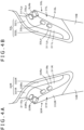
- FIG. 4A illustrates an enlarged perspective view of the grip part 30L at the left end.
- FIG. 4B illustrates an enlarged perspective view of the grip part 30R at the right end.
- the grip parts 30L and 30R include projecting portions 31L and 31R and recessed portions 32L and 32R, respectively.
- the projecting portions 31L and 31R project in a direction intersecting, in this example, orthogonal to the rear surface 10B of the coordinate input device main body part 10.
- the recessed portions 32L and 32R are disposed on the peripheries of the projecting portions 31L and 31R, respectively.
- a plurality of operation buttons 33La, 33Lb, 33Lc, and 33Ld which are examples of a plurality of operation parts, are disposed on the projecting portion 31L of the grip part 30L.
- a plurality of operation buttons 33Ra, 33Rb, 33Rc, and 33Rd which are examples of the plurality of operation parts, are disposed on the projecting portion 31R of the grip part 30R.
- the operation buttons 33La to 33Ld and 33Ra to 33Ld are configured by push button switches. It is noted that the operation buttons are not limited to push button switches and slide switches can be used.
- the grip part 30L is configured such that, in a state in which a right-handed operator performs a position indication operation input on the input surface 16S by holding the electronic pen 2 with the right hand, the right-handed operator can operate the plurality of operation buttons 33La, 33Lb, 33Lc, and 33Ld by putting the left hand around the rear surface 10B from the left end side of the coordinate input device main body part 10.
- the grip part 30R is configured such that, in a state in which a left-handed operator performs a position indication operation input on the input surface 16S by holding the electronic pen 2 with the left hand, the left-handed operator can operate the plurality of operation buttons 33Ra, 33Rb, 33Rc, and 33Rd by putting the right hand around the rear surface 10B from the right end side of the coordinate input device main body part 10.
- the projecting portion 31L is shaped and sized so as to be grippable by the operator with the left hand
- the projecting portion 31R is shaped and sized so as to be grippable by the operator with the right hand.
- the recessed portion 32L is disposed such that, when the operator grips the projecting portion 31L with the left hand, four fingers of the left hand other than the thumb can be inserted into the recessed portion 32L.
- the recessed portion 32R is formed such that, when the operator grips the projecting portion 31R with the right hand, four fingers of the right hand other than the thumb can be inserted into the recessed portion 32R (see FIG. 5 ).
- the projecting portion 31L includes, in this example, a side portion 311L which is in the direction intersecting the rear surface 10B of the coordinate input device main body part 10, and an upper surface portion 312L which faces and is separated from the rear surface 10B of the coordinate input device main body part 10 by a predetermined distance (see FIG. 4B ).
- the projecting portion 31R includes, in this example, a side portion 311R which is in the direction intersecting the rear surface 10B of the coordinate input device main body part 10, and an upper surface portion 312R which faces and is separated from the rear surface 10B of the coordinate input device main body part 10 by a predetermined distance (see FIG. 4A ).
- a side portion of the projecting portion 31L at the left end of the coordinate input device main body part 10 is formed so as to be flush with a side surface at the left end of the casing 11 of the coordinate input device main body part 10 as illustrated in FIGS. 1B , 2A , and 4 .
- a side portion of the projecting portion 31R at the right end of the coordinate input device main body part 10 is formed so as to be flush with a side portion at the right end of the casing 11 of the coordinate input device main body part 10 as illustrated in FIGS. 1B , 2A , and 4 .
- the grip parts 30L and 30R are positioned on an inner side of the rear surface, it may be difficult to reach the grip parts with hands. However, since the grip parts 30L and 30R are respectively disposed at the left end and the right end of the coordinate input device main body part 10 as in this example, the operator can easily operate the operation buttons on the grip part while operating the electronic pen 2.
- a length L (see FIG. 2A ) of each of the projecting portion 31L and the projecting portion 31R in the longitudinal direction of the coordinate input device main body part 10 is larger than a length thereof in the lateral direction of the coordinate input device main body part 10, that is, a width W (see FIG. 2A ) of each of the projecting portion 31L and the projecting portion 31R, and the width W of each of the projecting portion 31L and the projecting portion 31R becomes narrower toward an upward direction in the longitudinal direction of the coordinate input device main body part 10.
- the recessed portions 32L and 32R are respectively disposed on the peripheries of the projecting portions 31L and 31R except for the portions that are respectively flush with the left end and the right end of the coordinate input device main body part 10. That is, upper-side recessed portions 321L and 321R are formed so as to be respectively continuous with recessed portions 322L and 322R in the longitudinal direction. The upper-side recessed portions 321L and 321R are respectively on the peripheries of side portions 311La and 311Ra (see FIG.
- the recessed portions 322L and 322R are respectively formed adjacent to the peripheries of side portions 311Lb and 311Rb in a length L direction along the longitudinal direction of the coordinate input device main body part 10.
- the length L in the longitudinal direction of each of the projecting portions 31L and 31R has a length with which the corresponding projecting portion 31L or 31R can be gripped with three fingers of the middle finger, the ring finger, and the little finger of a hand or has a length larger than that.
- the width W of each of the projecting portions 31L and 31R has a width with which when the corresponding projecting portion 31L or 31R is gripped by putting a hand from the input surface 16S side of the coordinate input device main body part 10, tips of the middle finger, the ring finger, and the little finger of the hand are inserted into the corresponding recessed portion 322L or 322R, and balls of these fingers are in contact with the side portion of the corresponding projecting portion 31L or 31R, as illustrated in FIG. 5 .
- each of the recessed portions 32L and 32R (the length in the extending direction of the width direction of each of the projecting portions 31L and 31R) has, as illustrated in FIG. 5 , a width with which the ball of the index finger of the hand can be positioned on the corresponding side portion 311La or 311Ra and the balls of first joints of the middle finger, the ring finger, and the little finger can be positioned on the corresponding side portion 311Lb or 311Rb.
- the side portions 31 1La and 311Ra are on the upper side of the projecting portions 31L and 31R, respectively.
- the side portions 311Lb and 311Rb are in the length L direction of the projecting portions 31L and 31R, respectively.
- each of the upper surface portions 312L and 312R of the projecting portions 31L and 31R from the bottom of each of the recessed portions 32L and 32R has, as illustrated in FIG. 5 , a height with which the ball of the index finger and the balls of the first joints of the middle finger, the ring finger, and the little finger of the hand can be positioned on the corresponding side portion 311L or 311R of the projecting portions 31L and 31R.
- the height from the bottom of each of the recessed portions 32L and 32R to each of the upper surface portions 312L and 312R of the projecting portions 31L and 31R is not uniform and is configured so as to be different in the length L direction (the longitudinal direction of the coordinate input device main body part 10) of the projecting portions 31L and 31R.
- FIG. 6 is a cross-sectional view taken along line A-A of FIG. 2 and is a cross-sectional view of the grip part 30R at the right end.
- the upper surface portions 312L and 312R of the projecting portions 31L and 31R are configured such that the lower side thereof in the longitudinal direction of the rear surface 10B of the coordinate input device main body part 10 is, in this example, flush with the rear surface 10B of the coordinate input device main body part 10, and such that the height from the bottom of each of the recessed portions 32L and 32R increases more on the upper side of the upper surface portions 312L and 312R such that the upper surface portions 312L and 312R protrude from the rear surface 10B of the coordinate input device main body part 10.
- the recessed portions 32L and 32R are respectively formed adjacent to the peripheries of the projecting portions 31L and 31R in a state in which the bottom surfaces of the recessed portions 32L and 32R are lower than the rear surface 10B.
- angles formed by intersections between the side portions 311L and 311R of the projecting portions 31L and 31R and the respective bottoms of the recessed portions 32L and 32R are configured to be slightly obtuse as illustrated in FIGS. 4 and 6 , and the side portions 311L and 311R of the projecting portions 31L and 31R are configured to be slightly spread out toward the bottoms of the respective recessed portions 32L and 32R.
- the operator can easily grip the projecting portions 31L and 31R with the hand of the operator and can easily press against the side portions 311L and 311R of the projecting portions 31L and 31R with the balls of the fingers.
- the index finger of the left hand is inserted into the side portion 311La on the upper side of the side portion 311L of the projecting portion 31L in the longitudinal direction of the coordinate input device main body part 10, as illustrated in FIG. 5 .
- the grip part 30R is gripped by the right hand, the index finger of the right hand is inserted into the side portion 311Ra on the upper side of the side portion 311R of the projecting portion 31R in the longitudinal direction of the coordinate input device main body part 10.
- the operation buttons 33La and 33Lb and the operation buttons 33La and 33Lb are respectively disposed on the side portions 311La and 311Ra on the upper side of the projecting portions 31L and 31R and at different positions in the height direction of the projecting portions 31L and 31R
- the operation buttons 33La and 33Ra are planar knob switches with their pressing operation surfaces parallel to the respective side portions 311La and 311Ra.
- the operation buttons 33Lb and 33Rb are corner switches that have respective pressing operation surfaces and that can receive a pressing input in the direction intersecting the respective pressing operation surfaces.
- Each of the pressing operation surfaces has two surfaces including a surface parallel to the corresponding side portion 311La or 311Ra and a surface parallel to the corresponding upper surface portion 312L or 312R. It is noted that, since the side portions 311La and 311Ra on the upper side of the projecting portions 31L and 31R are higher than the others, the two operation buttons 33La and 33Lb and the operation buttons 33Ra and 33Rb can be disposed side by side as illustrated in the figure.
- the balls of the first joints of the middle finger, the ring finger, and the little finger of the left hand are in contact with the side portion 311Lb of the projecting portion 31L adjacent to the recessed portion 322L, as illustrated in FIG. 5 .
- the grip part 30R is gripped by the right hand, the balls of the first joints of the middle finger, the ring finger, and the little finger of the left hand are in contact with the side portion 311Lb of the projecting portion 31L adjacent to the recessed portion 322L, as illustrated in FIG. 5 .
- the operation buttons 33Lc and 33Rc are respectively disposed on the side portions 311Lb and 311Rb of the projecting portions 31L and 31R at positions with which the ball of the first joint of the middle figure is in contact
- the operation buttons 33Ld and 33Rd are respectively disposed on the side portions 311Lb and 311Rb of the projecting portions 31L and 31R at positions with which the ball of the first joint of the ring finger is in contact
- the operation buttons 33Lc and 33Rc and the operation buttons 33Ld and 33Rd are planar knob switches with their pressing operation surfaces parallel to the respective side portions 311La and 311Ra.
- Each of the operation buttons 33La to 33Ld and 33Ra to 33Rd is assigned any of various functions of the coordinate input device 1 according to the present embodiment with respect to the pressing operation thereof.
- the function assigned to each of the operation buttons 33La to 33Ld and 33Ra to 33Rd may be predetermined in advance.
- function settings of the operation buttons may be selected from a menu, and the function to each of the operation buttons may be selectively set.
- the menu activation and item selection such as selection and settings of the operation buttons from a menu can be performed on the basis of the result of the detection of the position indicated by a finger of the operator by the position detection sensor 12 of the capacitive coupling system.
- the grip parts 30L and 30R at the left end and the right end of the rear surface 10B of the coordinate input device main body part 10 are used for the left hand of a right-handed operator and for the right hand of a left-handed operator, respectively.
- the operation buttons at the identical positions to each other between the operation buttons 33La to 33Ld of the grip part 30L and the operation buttons 33Ra to 33Rd of the grip part 30R are assigned the identical functions.
- Examples of the functions assigned to the operation buttons 33La to 33Ld of the grip part 30L and the operation buttons 33Ra to 33Rd of the grip part 30R include “redo,” “undo,” “indication of display color intensity,” “resize,” and so forth. Needless to say, however, the examples are not limited thereto.
- the grip parts 30L and 30R are formed separately from the casing 11 of the coordinate input device main body part 10 and are formed so as to be fitted and attached to fitting portions for the grip parts 30L and 31R formed in the casing 11. Needless to say, however, the grip parts 30L and 30R may be formed integrally with portions on the rear surface 10A side of the casing 11 of the coordinate input device main body part 10.
- the operator holds the electronic pen 2 with his/her dominant hand and performs writing or drawing by a position indication input with the electronic pen 2 on the input surface 16S. Then, while performing the position indication input operation with the electronic pen 2, the operator performs a position indication operation on the input surface 16S with a finger of a non-dominant hand at an appropriate timing or grips the grip part 30L or 30R to operate the operation buttons 33La to 33Ld or the operation buttons 33Ra to 33Rd.
- the coordinate input device 1 receives the above-described operation input and performs processing and control corresponding to the operation input in an electrical processing unit.
- FIG. 7 illustrates an example of a configuration of the electrical processing unit of the coordinate input device 1 according to the present embodiment.
- the electronic pen 2 of the electromagnetic induction system includes a resonance circuit 2R as its circuit configuration.
- the resonance circuit 2R includes a position indication coil 2L and a resonance capacitor 2C which is connected in parallel to the position indication coil 2L.
- the position detection sensor 14 includes an X-axis direction loop coil group 141 and a Y-axis direction loop coil group 142, which are formed on the front and back sides of a substrate 140.
- the X-axis direction loop coil group 141 and the Y-axis direction loop coil group 142 are connected to a position detection circuit 151 via a selection circuit 143.
- the selection circuit 143 operates so as to sequentially select one or a plurality of loop coils from the two loop coil groups 141 and 142 in response to the reception of a selection control signal from the position detection circuit 151.
- the position detection circuit 151 transmits an alternating-current signal of a predetermined frequency to the electronic pen 2 through the loop coil(s) selected by the selection circuit 143.
- the electronic pen 2 receives the alternating-current signal from the position detection sensor 14 at the resonance circuit 2R and causes the alternating-current signal to be fed back from the resonance circuit 2R to the position detection sensor 14 through electromagnetic induction coupling.
- the induction voltage generated at the loop coil selected by the selection circuit 143 in response to the signal fed back from the electronic pen 2 is supplied to the position detection circuit 151.
- the position detection circuit 151 calculates the coordinate value of the position indicated by the electronic pen 2 in the X-axis and Y-axis directions of a detection region of the position detection sensor 14.
- the position detection circuit 151 supplies the calculated coordinate value of the position indicated by the electronic pen 2 to a control circuit 150.
- the position detection sensor 12 of the capacitive coupling system includes an X-axis direction linear conductor group 121 and a Y-axis direction linear conductor group 122, which are formed on the front and back of a transparent substrate 120.
- the X-axis direction linear conductor group 121 and the Y-axis direction linear conductor group 122 are connected to a position detection circuit 152 via a selection circuit 123.
- the selection circuit 123 sequentially selects one or a plurality of linear conductors from the Y-axis direction linear conductor group 122 in response to the reception of a selection control signal from the position detection circuit 152 and sequentially supplies a predetermined transmission signal such as a spreading code to the selected linear conductor(s). Then, reception signals of the transmission signals from the X-axis direction linear conductor group are received, and a reception process is performed. By detecting that the reception signal acquired at the position where a finger is present is different from the reception signals at the other positions, the position indicated by the finger is detected. The position detection circuit 152 supplies the detected coordinate value of the position indicated by the finger to the control circuit 150.
- an operation part interface (denoted as "I/F" in FIG. 7 ) 154 is connected to the control circuit 150, and each of the operation buttons 33La to 33Ld of the grip part 30L and each of the operation buttons 33La to 33Ld of the grip part 30R are connected to the operation part interface 154.
- the control circuit 150 has a function of detecting the operated operation button through the operation part interface 154 when any of the operation buttons 33La to 33Ld of the grip part 30L is operated or when any of the operation buttons 33La to 33Ld of the grip part 30L is operated.
- the control circuit 150 generates pen trace information or drawing information based on time-series data of coordinates of the position indicated by the electronic pen 2 and detected by the position detection circuit 151 and supplies the pen trace information or drawing information to a display control circuit 320.
- the display control circuit 320 generates display information based on the received pen trace information or drawing information, supplies the generated display information to the display device 13, and causes the display screen 133 to display the pen trace or drawing image using the electronic pen 2.
- control circuit 150 activates the function set corresponding to the coordinate position indicated by the finger and detected by the position detection circuit 152, generates display information corresponding to the function, and supplies the display information to the display control circuit 153.
- the display control circuit 320 supplies the display information corresponding to the received function to the display device 13 and causes the display screen 133 to display a display image such as a list of function menus or a list of setting items together with the pen trace or drawing image using the electronic pen 2.
- control circuit 150 changes and controls the color and size of the pen trace or the drawing image using the electronic pen 2 or performs control for "redoing” or “undoing” an indication input operation of the electronic pen 2 on the basis of any of the operation buttons 33La to 33Ld of the grip part 30L or any of the operation buttons 33La to 33Ld of the grip part 30L detected through the operation part interface 154.
- the display control circuit 153 reflects the display control corresponding to the control by the control circuit 150 in the display image on the display screen 133 of the display device 3.
- the operator performs a position indication input operation using the electronic pen 2 with one hand while gripping one of the grip parts 30L and 30R with the other hand and operating the operation buttons 33La to 33ld or the operation buttons 33Ra to 33Rd or performing a touch input on the input surface with a finger of the other hand.
- the operator can conveniently perform various function processes while performing a writing input with the electronic pen on the display screen.
- the operator when the operator grips the projecting portion 31L and 31R of the grip parts 30L or 30R with the left or right hand, the operator can not only perform a pressing operation on the operation button 33La or 33Ra or the operation button 33Lb or 33Rb with the index finger but also perform a pressing operation on the operation button 33Lc or 33Rc with the middle finger and the operation button 33Lc or 33Rc with the ring finger, respectively.
- the operator can recognize and correctly operate each of the operation buttons 33La to 33Ld of the grip part 30L or each of the operation buttons 33Ra to 33Rd of the grip part 30R without checking with his/her eyes, in addition to the effect of a muscle memory. Therefore, eve when the operator holds the electronic pen 2 with his/her dominant hand and performs a position indication input operation while gripping the projecting portion 31L or 31R of the grip parts 30L and 30R with the other hand and operates the operation buttons 33La to 33Ld or the operation buttons 33Ra to 33Rd, the operator does not need to operate the operation buttons while checking the positions of the operation buttons with his/her eyes, as before. This enables efficient input work.
- the coordinate input device 1 includes the coordinate input device main body part 10 and the stand part 20.
- the stand part 20 is not an essential constituent component in the coordinate input device according to the present disclosure, and only the coordinate input device main body part 10 may be included.
- the grip parts 30L and 30R are used for a left hand of a right-handed operator and for a right hand of a left-handed operator, respectively, and the operation buttons at the identical positions to each other between the operation buttons 33La to 33Ld of the grip part 30L and the operation buttons 33Ra to 33Rd of the grip part 30R are assigned the identical functions.
- the operation buttons 33La to 33Ld of the grip part 30L may be assigned different functions from the operation buttons 33Ra to 33Rd of the grip part 30R.
- the grip part is disposed at each of the left and right ends in the lateral direction of the coordinate input device main body part 10 having the rectangular outer shape, the grip part may be disposed on only one side. Further, the grip part may be disposed at either or both of the upper and lower ends in the longitudinal direction of the coordinate input device main body part 10 having the rectangular outer shape. Further, the number of grip parts may be three or more, instead of one or two. Further, the positions at which the operation buttons are disposed may be different between different grip parts.
- the grip part may be disposed in the substantial middle of the rear surface of the coordinate input device, instead of an end of the rear surface of the coordinate input device.
- the operation buttons as an example of the operation parts are disposed only on the side portion of the projecting portion of each grip part in the embodiment described above, the operation parts may be disposed on the upper surface portion of the projecting portion or on both the side portion and the upper surface portion thereof.
- each grip part can be configured without the recessed portion by forming the projecting portion from the rear surface of the coordinate input device.
- the operation buttons are used as an example of the operation parts in the embodiment described above, the operation parts are not limited to the operation buttons. Any of the operation parts, such as, for example, a touch sensor (touch panel), a wheel, and a trackball can be used as the operation parts as long as the user can operate them without visually checking. Further, the plurality of operation parts may be a combination of operation buttons, a touch sensor, a trackball, and the like, instead of the same type of operation parts such as a plurality of operation buttons, for example.
- each grip part is not limited to four and may be one. Further, any number of operation parts may be disposed as long as the operation buttons can be recognized by a muscle memory.
- the shape of the projecting portion of each grip part is not limited to the above-described example.
- the shape thereof may be such that a recessed portion is formed in the side portion of the projecting portion according to the position with which a ball of a finger is in contact when the projecting portion is gripped by a hand.
- the shape of the projecting portion is not limited to the shape having the side portion and the upper surface portion as in the example described above and can be a spherical shape, a columnar shape with a polygonal cross section, or various other shapes.
- each grip part may be disposed at any position as long as it is on the rear surface side of the coordinate input device.
- position detection sensors of the electromagnetic induction system and the capacitive coupling system are included in the embodiment described above, only the position detection sensor of one of the systems may be included. Further, needless to say, a position detection sensor of any other system may be used without limiting to the electromagnetic induction system or the capacitive coupling system.
- an electronic pen of a passive system may be used as an indicator with respect to the position detection sensor of the capacitive coupling system.
- the position detection sensor of the capacitive coupling system may use a position detection sensor and an electronic pen of an active capacitive coupling system.
- the coordinate input device includes the display device
- the display device may be a separate body, and the coordinate input device may not include the display device.
Landscapes
- Engineering & Computer Science (AREA)
- Theoretical Computer Science (AREA)
- General Engineering & Computer Science (AREA)
- Physics & Mathematics (AREA)
- Human Computer Interaction (AREA)
- General Physics & Mathematics (AREA)
- Computer Hardware Design (AREA)
- Electromagnetism (AREA)
- Quality & Reliability (AREA)
- Position Input By Displaying (AREA)
- Input From Keyboards Or The Like (AREA)
Abstract
Description
- The present disclosure relates to a coordinate input device including a position detection sensor that detects a position indicated by an indicator such as an electronic pen or a finger.
- Coordinate input devices including position detection sensors that detect a position indicated by an indicator such as an electronic pen or a finger are widely used not only for a writing input of characters but also for drawing of animated images and the like. A coordinate input device of this type includes a display screen including a flat display made of, for example, a liquid crystal display and is configured such that a trajectory based on the position indicated by the indicator and detected by the position detection sensor is displayed on the display screen or such that display corresponding to an indication input based on the position indicated by the indicator is performed (see Patent Document 1 (
Japanese Patent No. 5808001 -
FIG. 8 is a view for describing an example of a conventional coordinate input device of this type. As illustrated inFIG. 8 , a coordinate input device 100 in this example includes adisplay device part 101, which includes adisplay screen 101D, and aposition detection sensor 102, which detects the position indicated by anelectronic pen 200. - The
position detection sensor 102 and theelectronic pen 200 use, for example, the electromagnetic induction system. As illustrated inFIG. 8 , theposition detection sensor 102 is disposed on a rear side of thedisplay screen 101D in a superimposed manner such that a position detection region of the position detection sensor and a display region of thedisplay screen 101D are superimposed on each other. - Moreover, as illustrated in
FIG. 8 , an operator who performs a position indication operation input with theelectronic pen 200 holds theelectronic pen 200 with his/her hand and performs a coordinate input by performing a position indication input on the display screen 102D, which is an input surface. - Moreover, as illustrated in
FIG. 8 , the coordinate input device 100 includes a plurality ofoperation buttons 103L and a plurality ofoperation buttons 103R for assistance operation of a position indication input with theelectronic pen 200. Here, as illustrated inFIG. 8 , the plurality ofoperation buttons 103L are disposed on the left side of thedisplay screen 101D so that a right-handed operator can operate the buttons with his/her left hand when the operator performs a position indication input by holding theelectronic pen 200 with his/her right hand. Further, the plurality ofoperation buttons 103R are disposed on the right side of thedisplay screen 101D so that a left-handed operator can operate the buttons with his/her right hand when the operator performs a position indication input by holding theelectronic pen 200 with his/her left hand. - While performing a position indication with the
electronic pen 200 on the input surface of thecoordinate input device 1, the operator holding theelectronic pen 200 can operate theoperation buttons electronic pen 200. - Patent Document 1:
Japanese Patent No. 5808001 - However, in the coordinate input device 100 according to the above-described example illustrated in
FIG. 8 , the plurality ofoperation buttons operation buttons - Further, in the coordinate input device 100 according to the above-described example illustrated in
FIG. 8 , the plurality ofoperation buttons operation buttons operation buttons operation buttons electronic pen 200 is temporarily paused, resulting in poor work efficiency. - It is an object of the present disclosure to provide a coordinate input device capable of solving the problems described above.
- In order to solve the problems described above, there is provided a coordinate input device including a position detection sensor which, in operation, detects a position indicated by an indicator, a casing including a rear surface and housing the position detection sensor, the rear surface facing an input surface, the input surface being a surface on which an input operation for inputting the position indicated by the indicator is performed and corresponding to a position detection region of the position detection sensor, and at least one grip part disposed on the rear surface of the casing, in which the at least one grip part includes a projecting portion that projects in a direction intersecting the rear surface and one or more operation parts are disposed on the projecting portion.
- In the coordinate input device having the configuration described above, because the operation parts are disposed on the grip part disposed on the rear surface of the casing, the operation parts do not need to be disposed on an input surface side. Therefore, the position detection region on the input surface side can be enlarged.
- Further, because the operation parts are disposed on the projecting portion of the grip part gripped by an operator, the operator can recognize the operation parts at the same positions as when the operator grips the grip part. Therefore, the operator can recognize the operation parts by the muscle memory. Accordingly, the operator does not need to check the positions of the operation parts with his/her eyes and can perform efficient input work by operating the operation parts on the grip part with a hand opposite to a hand holding the indicator, for example.
-
-
FIG. 1 is a perspective view for describing the appearance of a coordinate input device according to an embodiment of the present disclosure. -
FIG. 2 illustrates a rear view and a side view of the coordinate input device according to an embodiment of the present disclosure. -
FIG. 3 is an exploded perspective view illustrating an example of an internal configuration of the coordinate input device according to an embodiment of the present disclosure. -
FIG. 4 is an enlarged perspective view of an example of a configuration of a main portion of the coordinate input device according to an embodiment of the present disclosure. -
FIG. 5 is a view for describing the example of the configuration of the main portion of the coordinate input device according to an the embodiment of the present disclosure. -
FIG. 6 is a cross-sectional view taken along line A-A of the rear view ofFIG. 2A . -
FIG. 7 is a diagram for describing an example of an electrical configuration of the coordinate input device according to an the embodiment of the present disclosure. -
FIG. 8 is a view for describing a conventional coordinate input device. - Hereinafter, a coordinate input device according to an embodiment of the present disclosure is described with reference to the drawings.
-
FIGS. 1 and2 are views for describing the appearance of acoordinate input device 1 according to the present embodiment. Thecoordinate input device 1 according to the present embodiment includes a coordinate input devicemain body part 10 and astand part 20 that is coupled to the coordinate input devicemain body part 10. - In this example, the coordinate input device
main body part 10 has a rectangular outer shape and is configured to be thin with a predetermined thickness. In this example, moreover, the coordinate input devicemain body part 10 has two rectangular surfaces orthogonal to a thickness direction. One surface side thereof is afront surface 10A side, and the other surface side is arear surface 10B side. -
FIG. 1A is an external perspective view of thecoordinate input device 1 as viewed from thefront surface 10A side, andFIG. 1B is an external perspective view thereof as viewed from therear surface 10B side. Further,FIG. 2A is a rear view of thecoordinate input device 1, andFIG. 2B is a left side view of thecoordinate input device 1. Moreover,FIG. 3 is an exploded perspective view illustrating an example of an internal configuration of thecoordinate input device 1. - Inside a
casing 11 of the coordinate input devicemain body part 10, in this example, as illustrated inFIG. 3 , aposition detection sensor 12 of a capacitive coupling system, adisplay device 13, aposition detection sensor 14 of an electromagnetic induction system, acontrol circuit board 15, and aplanar member 16, which is made of a transparent material such as, for example, glass or resin, are arranged in order in a superimposed manner. - The
casing 11 is made of, for example, a synthetic resin. A recessed portion is formed in thiscasing 11 to house theposition detection sensor 12, thedisplay device 13, theposition detection sensor 14, thecontrol circuit board 15, and so forth. An opening side of the recessed portion of thecasing 11 is thefront surface 10A side of the coordinate input devicemain body part 10. After theposition detection sensor 12, thedisplay device 13, theposition detection sensor 14, thecontrol circuit board 15, and so forth are housed in the recessed portion of thecasing 11, the opening side of the recessed portion of thecasing 11 is closed by theplanar member 16, thereby forming the coordinate input devicemain body part 10. - The
display device 13 includes a flat display such as a liquid crystal display or an organic EL (electroluminescence) display and includes adisplay screen 133 in which a large number ofdisplay pixels 132 are arranged in an X-axis direction (lateral direction) and a large number ofdisplay pixels 132 are arranged in a Y-axis direction (longitudinal direction) orthogonal to the X-axis direction on adisplay board 131. - The
position detection sensor 12 of the capacitive coupling system includes, for example, a plurality of linear X conductors and a plurality of linear Y conductors. The plurality of linear X conductors are arranged in the X-axis direction, which is the lateral direction of the rectangular outer shape of the coordinate input devicemain body part 10. The plurality of linear Y conductors are arranged in the Y-axis direction (the longitudinal direction of the rectangular outer shape of the coordinate input device main body part 10) so as to orthogonally intersect the plurality of X conductors. Theposition detection sensor 12 is disposed on a front surface side of thedisplay screen 133 of thedisplay device 13 and is disposed such that a position detection region of theposition detection sensor 2 and a display region of thedisplay screen 133 of thedisplay device 13 are superimposed on each other. - Further, the
position detection sensor 14 of the electromagnetic induction system includes an X-axis direction loop coil group including a plurality of loop coils arranged in the X-axis direction and a Y-axis direction loop coil group including a plurality of loop coils arranged in the Y-axis direction. Theposition detection sensor 14 is disposed on a rear surface side of thedisplay screen 133 of thedisplay device 13 and is disposed such that a position detection region of the position detection sensor and the display region of thedisplay device 13 are superimposed on each other. Therefore, theposition detection sensor 12 and theposition detection sensor 14 are in the relationship in which their position detection regions are disposed so as to be superimposed on each other. - In other words, the position detection region of the
position detection sensor 12, the position detection region of theposition detection sensor 14, and the display region of thedisplay screen 133 of thedisplay device 13 have approximately the same size and are in the relationship in which they are disposed so as to be superimposed on each other. - A contact detection circuit of a capacitive system to which the
position detection sensor 12 is connected, a position detection circuit of the electromagnetic induction system to which theposition detection sensor 14 is connected, a display control circuit of thedisplay device 11, a control circuit which includes a microcomputer for controlling those circuits and monitoring the operation of a plurality of operation buttons described later to generate corresponding control signals, other electronic components, and copper foil wiring patterns are mounted on thecontrol circuit board 15. - A
surface 16S on one side of theplanar member 16, which is made of a transparent material such as glass or resin, serves as an input surface when anelectronic pen 2 or a finger as an example of an indicator performs an input operation for inputting a position indication by contacting the input surface. Hereafter, thesurface 16S on one side of the planar member is referred to as aninput surface 16S of the coordinateinput device 1. It is noted that, in the coordinateinput device 1 according to the present embodiment, an electronic pen of the electromagnetic induction system is used as theelectronic pen 2 to enable a high-definition coordinate input and the position indicated by theelectronic pen 2 is detected by theposition detection sensor 14. - The
stand part 20 includes abase portion 21, anarm portion 22, and a mainbody coupling portion 23 which is coupled to therear surface 10B of the coordinate input devicemain body part 10. - The
base portion 21 includes, in this example, a planar plate-like body portion 211 and a connectingportion 212 which is connected to thearm portion 22. The plate-like body portion 211 of thebase portion 21 is placed such that a plate-like surface on a bottom surface side of the plate-like body portion 211 is in contact with a top surface (seeFIG. 2B ) of a mounting base TB such as a table or the like on which the coordinateinput device 1 is placed. The connectingportion 212 is disposed so as to project from a top surface of the plate-like body portion 211. - The main
body coupling portion 23 includes a fixedcoupling portion 231 and a connectingportion 232. The fixedcoupling portion 231 is deposited and fixed at, in this example, substantially the center position of the rear surface 10a of the coordinate input devicemain body part 10. The connectingportion 232 is connected to thearm portion 22. The fixedcoupling portion 231 has, in this example, a circular plate-like body. The connectingportion 232 is disposed so as to project in a direction orthogonal to therear surface 10B from a surface that is included in the fixedcoupling portion 231 having the plate-like body and that is parallel to therear surface 10B. - The
arm portion 22 is a rectangular plate-like member and is disposed so as to connect thebase portion 21 and the mainbody coupling portion 23. In the present embodiment, thearm portion 22 is shaped such that an end edge thereof on thebase portion 21 side and an end edge thereof on the mainbody coupling portion 23 side are straight lines parallel to each other. - Moreover, an end of the
arm portion 22 on thebase portion 21 side is coupled to and attached to the connectingportion 212 of thebase portion 21 in a state in which thearm portion 22 is turnable (swingable) relative to thebase portion 21 around a turning axis (not illustrated) in a direction parallel to the straight end edge of thearm portion 22 on thebase portion 21 side as indicated by an arrow AR1 inFIGS. 1B and2B . - In this case, the
arm portion 22 is turnably (swingably) attached to the connectingportion 212 of thebase portion 21 in a state in which the angle between thearm portion 22 and thebase portion 21 can be locked at any position. The turning (swinging) of thearm portion 22 relative to thebase portion 21 in the direction indicated by the arrow AR1 enables the change of the height position of the coordinate input devicemain body part 10 relative to the mounting base TB. - Further, the main
body coupling portion 23 is attached to thearm portion 22 by coupling an end of the arm portion on the mainbody coupling portion 23 side to the connectingportion 232 of the mainbody coupling portion 23 in a state in which the mainbody coupling portion 23 is turnable about a turning axis (not illustrated) in a direction parallel to the straight end edge of thearm portion 22 on the mainbody coupling portion 23 side. In this case, the mainbody coupling portion 23 is turnably attached to thearm portion 22 at the connectingportion 232 in a state in which the angle between the mainbody coupling portion 23 and thearm portion 22 can be locked at any position. - Accordingly, the coordinate input device
main body part 10, to which the mainbody coupling portion 23 is fixed, is turnable in a tilt direction around the turning axis in the direction parallel to the straight end edge of thearm portion 22 on the mainbody coupling portion 23 side, that is, around a turning axis AX (seeFIG. 1A ), which is the turning center, in the lateral direction at the intermediate position in the longitudinal direction of the coordinate input devicemain body part 10 having the rectangular outer shape, as indicated by an arrow AR2 inFIGS. 1B and2B . That is, the coordinate input devicemain body part 10 is configured such that the angle between a front surface direction of theinput surface 16S of the coordinate input devicemain body part 10 and the top surface of the mounting base TB can be changed. It is noted that, in this case, the position of the turning axis of the turning of the coordinate input devicemain body part 10 in the tilt direction corresponds to the position at which the mainbody coupling portion 23 of thestand part 20 is coupled on therear surface 10B of the coordinate input devicemain body part 10 and is not limited to the center position in the longitudinal direction as illustrated inFIG. 1A . - In the coordinate
input device 1 according to the present embodiment,grip parts rear surface 10B of the coordinate input devicemain body part 10, in this example, near the end edges in the lateral direction of the coordinate input devicemain body part 10. In the present embodiment, thegrip part 30L is configured so as to be grippable by a right-handed operator with his/her left hand while thegrip part 30R is configured so as to be grippable by a left-handed operator with his/her right hand. Thesegrip parts grip parts FIG. 4A illustrates an enlarged perspective view of thegrip part 30L at the left end.FIG. 4B illustrates an enlarged perspective view of thegrip part 30R at the right end. - It is noted that, in the present embodiment, since the coordinate input device
main body part 10 is held by thestand part 20, a space into which a hand is inserted can be secured on therear surface 10B side of the coordinate input devicemain body part 10. - The
grip parts portions portions portions rear surface 10B of the coordinate input devicemain body part 10. The recessedportions portions portion 31L of thegrip part 30L. Similarly, a plurality of operation buttons 33Ra, 33Rb, 33Rc, and 33Rd, which are examples of the plurality of operation parts, are disposed on the projectingportion 31R of thegrip part 30R. In this example, the operation buttons 33La to 33Ld and 33Ra to 33Ld are configured by push button switches. It is noted that the operation buttons are not limited to push button switches and slide switches can be used. - The
grip part 30L is configured such that, in a state in which a right-handed operator performs a position indication operation input on theinput surface 16S by holding theelectronic pen 2 with the right hand, the right-handed operator can operate the plurality of operation buttons 33La, 33Lb, 33Lc, and 33Ld by putting the left hand around therear surface 10B from the left end side of the coordinate input devicemain body part 10. Further, thegrip part 30R is configured such that, in a state in which a left-handed operator performs a position indication operation input on theinput surface 16S by holding theelectronic pen 2 with the left hand, the left-handed operator can operate the plurality of operation buttons 33Ra, 33Rb, 33Rc, and 33Rd by putting the right hand around therear surface 10B from the right end side of the coordinate input devicemain body part 10. - For this purpose, the projecting
portion 31L is shaped and sized so as to be grippable by the operator with the left hand, and the projectingportion 31R is shaped and sized so as to be grippable by the operator with the right hand. Moreover, the recessedportion 32L is disposed such that, when the operator grips the projectingportion 31L with the left hand, four fingers of the left hand other than the thumb can be inserted into the recessedportion 32L. Further, the recessedportion 32R is formed such that, when the operator grips the projectingportion 31R with the right hand, four fingers of the right hand other than the thumb can be inserted into the recessedportion 32R (seeFIG. 5 ). - The projecting
portion 31L includes, in this example, aside portion 311L which is in the direction intersecting therear surface 10B of the coordinate input devicemain body part 10, and anupper surface portion 312L which faces and is separated from therear surface 10B of the coordinate input devicemain body part 10 by a predetermined distance (seeFIG. 4B ). Similarly, the projectingportion 31R includes, in this example, aside portion 311R which is in the direction intersecting therear surface 10B of the coordinate input devicemain body part 10, and anupper surface portion 312R which faces and is separated from therear surface 10B of the coordinate input devicemain body part 10 by a predetermined distance (seeFIG. 4A ). - Moreover, in this example, in the
grip part 30L disposed at the left end of the coordinate input devicemain body part 10, a side portion of the projectingportion 31L at the left end of the coordinate input devicemain body part 10 is formed so as to be flush with a side surface at the left end of thecasing 11 of the coordinate input devicemain body part 10 as illustrated inFIGS. 1B ,2A , and4 . Further, in this example, in thegrip part 30R disposed at the right end of the coordinate input devicemain body part 10, a side portion of the projectingportion 31R at the right end of the coordinate input devicemain body part 10 is formed so as to be flush with a side portion at the right end of thecasing 11 of the coordinate input devicemain body part 10 as illustrated inFIGS. 1B ,2A , and4 . - If the
grip parts grip parts main body part 10 as in this example, the operator can easily operate the operation buttons on the grip part while operating theelectronic pen 2. - In the present embodiment, a length L (see
FIG. 2A ) of each of the projectingportion 31L and the projectingportion 31R in the longitudinal direction of the coordinate input devicemain body part 10 is larger than a length thereof in the lateral direction of the coordinate input devicemain body part 10, that is, a width W (seeFIG. 2A ) of each of the projectingportion 31L and the projectingportion 31R, and the width W of each of the projectingportion 31L and the projectingportion 31R becomes narrower toward an upward direction in the longitudinal direction of the coordinate input devicemain body part 10. - Moreover, the recessed
portions portions main body part 10. That is, upper-side recessedportions portions portions FIG. 4 ) on the upper side in the longitudinal direction of the coordinate input devicemain body part 10 within theside portions portions rear surface 10B of the coordinate input devicemain body part 10. The recessedportions main body part 10. - As illustrated in
FIG. 5 , the length L in the longitudinal direction of each of the projectingportions portion portions portion input surface 16S side of the coordinate input devicemain body part 10, tips of the middle finger, the ring finger, and the little finger of the hand are inserted into the corresponding recessedportion portion FIG. 5 . - Moreover, the width of each of the recessed
portions portions FIG. 5 , a width with which the ball of the index finger of the hand can be positioned on the corresponding side portion 311La or 311Ra and the balls of first joints of the middle finger, the ring finger, and the little finger can be positioned on the corresponding side portion 311Lb or 311Rb. The side portions 31 1La and 311Ra are on the upper side of the projectingportions portions - Further, the height of each of the
upper surface portions portions portions FIG. 5 , a height with which the ball of the index finger and the balls of the first joints of the middle finger, the ring finger, and the little finger of the hand can be positioned on thecorresponding side portion portions portions upper surface portions portions portions -
FIG. 6 is a cross-sectional view taken along line A-A ofFIG. 2 and is a cross-sectional view of thegrip part 30R at the right end. As illustrated inFIG. 6 as well asFIGS. 1B and4 , theupper surface portions portions rear surface 10B of the coordinate input devicemain body part 10 is, in this example, flush with therear surface 10B of the coordinate input devicemain body part 10, and such that the height from the bottom of each of the recessedportions upper surface portions upper surface portions rear surface 10B of the coordinate input devicemain body part 10. - Moreover, in the present embodiment, as illustrated in
FIGS. 2B and6 , the recessedportions portions portions rear surface 10B. By forming thegrip parts portions rear surface 10B can be suppressed, and the optimum grip can be ensured. - In this case, the angles formed by intersections between the
side portions portions portions FIGS. 4 and6 , and theside portions portions portions portions side portions portions - Moreover, when the
grip part 30L is gripped by the left hand, the index finger of the left hand is inserted into the side portion 311La on the upper side of theside portion 311L of the projectingportion 31L in the longitudinal direction of the coordinate input devicemain body part 10, as illustrated inFIG. 5 . Similarly, when thegrip part 30R is gripped by the right hand, the index finger of the right hand is inserted into the side portion 311Ra on the upper side of theside portion 311R of the projectingportion 31R in the longitudinal direction of the coordinate input devicemain body part 10. - In the present embodiment, as illustrated in
FIGS. 1B ,2A , and4 , the operation buttons 33La and 33Lb and the operation buttons 33La and 33Lb are respectively disposed on the side portions 311La and 311Ra on the upper side of the projectingportions portions upper surface portion portions - Moreover, when the
grip part 30L is gripped by the left hand, the balls of the first joints of the middle finger, the ring finger, and the little finger of the left hand are in contact with the side portion 311Lb of the projectingportion 31L adjacent to the recessedportion 322L, as illustrated inFIG. 5 . Similarly, when thegrip part 30R is gripped by the right hand, the balls of the first joints of the middle finger, the ring finger, and the little finger of the left hand are in contact with the side portion 311Lb of the projectingportion 31L adjacent to the recessedportion 322L, as illustrated inFIG. 5 . - As illustrated in
FIGS. 4A and 4B , in the present embodiment, the operation buttons 33Lc and 33Rc are respectively disposed on the side portions 311Lb and 311Rb of the projectingportions portions - Each of the operation buttons 33La to 33Ld and 33Ra to 33Rd is assigned any of various functions of the coordinate
input device 1 according to the present embodiment with respect to the pressing operation thereof. The function assigned to each of the operation buttons 33La to 33Ld and 33Ra to 33Rd may be predetermined in advance. Alternatively, function settings of the operation buttons may be selected from a menu, and the function to each of the operation buttons may be selectively set. In this example, the menu activation and item selection such as selection and settings of the operation buttons from a menu can be performed on the basis of the result of the detection of the position indicated by a finger of the operator by theposition detection sensor 12 of the capacitive coupling system. - In the present embodiment, as described above, the
grip parts rear surface 10B of the coordinate input devicemain body part 10 are used for the left hand of a right-handed operator and for the right hand of a left-handed operator, respectively. The operation buttons at the identical positions to each other between the operation buttons 33La to 33Ld of thegrip part 30L and the operation buttons 33Ra to 33Rd of thegrip part 30R are assigned the identical functions. - Examples of the functions assigned to the operation buttons 33La to 33Ld of the
grip part 30L and the operation buttons 33Ra to 33Rd of thegrip part 30R include "redo," "undo," "indication of display color intensity," "resize," and so forth. Needless to say, however, the examples are not limited thereto. - It is noted that, in the present embodiment, the
grip parts casing 11 of the coordinate input devicemain body part 10 and are formed so as to be fitted and attached to fitting portions for thegrip parts casing 11. Needless to say, however, thegrip parts rear surface 10A side of thecasing 11 of the coordinate input devicemain body part 10. - In the coordinate
input device 1 configured as described above, the operator holds theelectronic pen 2 with his/her dominant hand and performs writing or drawing by a position indication input with theelectronic pen 2 on theinput surface 16S. Then, while performing the position indication input operation with theelectronic pen 2, the operator performs a position indication operation on theinput surface 16S with a finger of a non-dominant hand at an appropriate timing or grips thegrip part - The coordinate
input device 1 according to the present embodiment receives the above-described operation input and performs processing and control corresponding to the operation input in an electrical processing unit. -
FIG. 7 illustrates an example of a configuration of the electrical processing unit of the coordinateinput device 1 according to the present embodiment. As illustrated inFIG. 7 , theelectronic pen 2 of the electromagnetic induction system includes aresonance circuit 2R as its circuit configuration. Theresonance circuit 2R includes aposition indication coil 2L and aresonance capacitor 2C which is connected in parallel to theposition indication coil 2L. - Moreover, the
position detection sensor 14 includes an X-axis directionloop coil group 141 and a Y-axis direction loop coil group 142, which are formed on the front and back sides of asubstrate 140. The X-axis directionloop coil group 141 and the Y-axis direction loop coil group 142 are connected to aposition detection circuit 151 via aselection circuit 143. Theselection circuit 143 operates so as to sequentially select one or a plurality of loop coils from the twoloop coil groups 141 and 142 in response to the reception of a selection control signal from theposition detection circuit 151. - The
position detection circuit 151 transmits an alternating-current signal of a predetermined frequency to theelectronic pen 2 through the loop coil(s) selected by theselection circuit 143. Theelectronic pen 2 receives the alternating-current signal from theposition detection sensor 14 at theresonance circuit 2R and causes the alternating-current signal to be fed back from theresonance circuit 2R to theposition detection sensor 14 through electromagnetic induction coupling. - The induction voltage generated at the loop coil selected by the
selection circuit 143 in response to the signal fed back from theelectronic pen 2 is supplied to theposition detection circuit 151. On the basis of the level of the voltage value of the induction voltage generated at each loop coil, theposition detection circuit 151 calculates the coordinate value of the position indicated by theelectronic pen 2 in the X-axis and Y-axis directions of a detection region of theposition detection sensor 14. Theposition detection circuit 151 supplies the calculated coordinate value of the position indicated by theelectronic pen 2 to acontrol circuit 150. - The
position detection sensor 12 of the capacitive coupling system includes an X-axis directionlinear conductor group 121 and a Y-axis directionlinear conductor group 122, which are formed on the front and back of atransparent substrate 120. The X-axis directionlinear conductor group 121 and the Y-axis directionlinear conductor group 122 are connected to aposition detection circuit 152 via aselection circuit 123. - Moreover, in this example, the
selection circuit 123 sequentially selects one or a plurality of linear conductors from the Y-axis directionlinear conductor group 122 in response to the reception of a selection control signal from theposition detection circuit 152 and sequentially supplies a predetermined transmission signal such as a spreading code to the selected linear conductor(s). Then, reception signals of the transmission signals from the X-axis direction linear conductor group are received, and a reception process is performed. By detecting that the reception signal acquired at the position where a finger is present is different from the reception signals at the other positions, the position indicated by the finger is detected. Theposition detection circuit 152 supplies the detected coordinate value of the position indicated by the finger to thecontrol circuit 150. - In the coordinate
input device 1 according to the present embodiment, an operation part interface (denoted as "I/F" inFIG. 7 ) 154 is connected to thecontrol circuit 150, and each of the operation buttons 33La to 33Ld of thegrip part 30L and each of the operation buttons 33La to 33Ld of thegrip part 30R are connected to theoperation part interface 154. - The
control circuit 150 has a function of detecting the operated operation button through theoperation part interface 154 when any of the operation buttons 33La to 33Ld of thegrip part 30L is operated or when any of the operation buttons 33La to 33Ld of thegrip part 30L is operated. - Then, the
control circuit 150 generates pen trace information or drawing information based on time-series data of coordinates of the position indicated by theelectronic pen 2 and detected by theposition detection circuit 151 and supplies the pen trace information or drawing information to a display control circuit 320. The display control circuit 320 generates display information based on the received pen trace information or drawing information, supplies the generated display information to thedisplay device 13, and causes thedisplay screen 133 to display the pen trace or drawing image using theelectronic pen 2. - Further, the
control circuit 150 activates the function set corresponding to the coordinate position indicated by the finger and detected by theposition detection circuit 152, generates display information corresponding to the function, and supplies the display information to thedisplay control circuit 153. The display control circuit 320 supplies the display information corresponding to the received function to thedisplay device 13 and causes thedisplay screen 133 to display a display image such as a list of function menus or a list of setting items together with the pen trace or drawing image using theelectronic pen 2. - Moreover, in the present embodiment, the
control circuit 150 changes and controls the color and size of the pen trace or the drawing image using theelectronic pen 2 or performs control for "redoing" or "undoing" an indication input operation of theelectronic pen 2 on the basis of any of the operation buttons 33La to 33Ld of thegrip part 30L or any of the operation buttons 33La to 33Ld of thegrip part 30L detected through theoperation part interface 154. Thedisplay control circuit 153 reflects the display control corresponding to the control by thecontrol circuit 150 in the display image on thedisplay screen 133 of the display device 3. - In the coordinate
input device 1 according to the present embodiment configured as described above, the operator performs a position indication input operation using theelectronic pen 2 with one hand while gripping one of thegrip parts - In this case, as illustrated in
FIG. 5 , when the operator grips the projectingportion grip parts - Therefore, the operator can recognize and correctly operate each of the operation buttons 33La to 33Ld of the
grip part 30L or each of the operation buttons 33Ra to 33Rd of thegrip part 30R without checking with his/her eyes, in addition to the effect of a muscle memory. Therefore, eve when the operator holds theelectronic pen 2 with his/her dominant hand and performs a position indication input operation while gripping the projectingportion grip parts - The coordinate
input device 1 according to the embodiment described above includes the coordinate input devicemain body part 10 and thestand part 20. However, thestand part 20 is not an essential constituent component in the coordinate input device according to the present disclosure, and only the coordinate input devicemain body part 10 may be included. - It is noted that, in the embodiment described above, the
grip parts grip part 30L and the operation buttons 33Ra to 33Rd of thegrip part 30R are assigned the identical functions. However, the operation buttons 33La to 33Ld of thegrip part 30L may be assigned different functions from the operation buttons 33Ra to 33Rd of thegrip part 30R. - Further, although the grip part is disposed at each of the left and right ends in the lateral direction of the coordinate input device
main body part 10 having the rectangular outer shape, the grip part may be disposed on only one side. Further, the grip part may be disposed at either or both of the upper and lower ends in the longitudinal direction of the coordinate input devicemain body part 10 having the rectangular outer shape. Further, the number of grip parts may be three or more, instead of one or two. Further, the positions at which the operation buttons are disposed may be different between different grip parts. - Further, as long as the grip part is disposed at a position that can be reached and gripped by a hand of the operator, the grip part may be disposed in the substantial middle of the rear surface of the coordinate input device, instead of an end of the rear surface of the coordinate input device.
- Further, although the operation buttons as an example of the operation parts are disposed only on the side portion of the projecting portion of each grip part in the embodiment described above, the operation parts may be disposed on the upper surface portion of the projecting portion or on both the side portion and the upper surface portion thereof.
- Further, although the recessed portion is formed adjacent to the projecting portion of each grip part in the embodiment described above, each grip part can be configured without the recessed portion by forming the projecting portion from the rear surface of the coordinate input device.
- Further, although the operation buttons are used as an example of the operation parts in the embodiment described above, the operation parts are not limited to the operation buttons. Any of the operation parts, such as, for example, a touch sensor (touch panel), a wheel, and a trackball can be used as the operation parts as long as the user can operate them without visually checking. Further, the plurality of operation parts may be a combination of operation buttons, a touch sensor, a trackball, and the like, instead of the same type of operation parts such as a plurality of operation buttons, for example.
- Further, the number of operation parts disposed on the projecting portion of each grip part is not limited to four and may be one. Further, any number of operation parts may be disposed as long as the operation buttons can be recognized by a muscle memory.
- Further, the shape of the projecting portion of each grip part is not limited to the above-described example. For example, the shape thereof may be such that a recessed portion is formed in the side portion of the projecting portion according to the position with which a ball of a finger is in contact when the projecting portion is gripped by a hand. Further, the shape of the projecting portion is not limited to the shape having the side portion and the upper surface portion as in the example described above and can be a spherical shape, a columnar shape with a polygonal cross section, or various other shapes.
- Further, the outer shape of the coordinate input device does not have to be a rectangle as in the embodiment described above and may be an oval, a circle, a polygon, or the like. In such cases, each grip part may be disposed at any position as long as it is on the rear surface side of the coordinate input device.
- Further, although both the position detection sensors of the electromagnetic induction system and the capacitive coupling system are included in the embodiment described above, only the position detection sensor of one of the systems may be included. Further, needless to say, a position detection sensor of any other system may be used without limiting to the electromagnetic induction system or the capacitive coupling system.
- It is noted that, instead of a finger only, an electronic pen of a passive system may be used as an indicator with respect to the position detection sensor of the capacitive coupling system. Further, the position detection sensor of the capacitive coupling system may use a position detection sensor and an electronic pen of an active capacitive coupling system.
- Further, although the coordinate input device according to the embodiment described above includes the display device, the display device may be a separate body, and the coordinate input device may not include the display device.
-
- 1: Coordinate input device
- 2: Electronic pen
- 10: Coordinate input device main body part
- 11: Casing
- 12: Position detection sensor
- 13: Display device
- 14: Position detection sensor
- 15: Control circuit board
- 16: Planar member
- 20: Stand part
- 30L and 30R: Grip part
- 31L and 31R: Projecting portion
- 32L and 32R: Recessed portion
- 33La to 33Ld, 33Ra to 33Rd: Operation button
- The various embodiments described above can be combined to provide further embodiments. Aspects of the embodiments can be modified, if necessary to employ concepts of the various patents, applications and publications to provide yet further embodiments.
- These and other changes can be made to the embodiments in light of the above-detailed description. In general, in the following claims, the terms used should not be construed to limit the claims to the specific embodiments disclosed in the specification and the claims, but should be construed to include all possible embodiments along with the full scope of equivalents to which such claims are entitled. Accordingly, the claims are not limited by the disclosure.
Claims (15)
- A coordinate input device, comprising:a position detection sensor which, in operation, detects a position indicated by an indicator;a casing including a rear surface and housing the position detection sensor, the rear surface facing an input surface, the input surface being a surface on which an input operation for inputting the position indicated by the indicator is performed and corresponding to a position detection region of the position detection sensor; andat least one grip part disposed on the rear surface of the casing,wherein the at least one grip part includes a projecting portion that projects in a direction intersecting the rear surface, and one or more operation parts are disposed on the projecting portion.
- The coordinate input device according to claim 1, wherein the at least one grip part is disposed adjacent to an end edge of the rear surface of the casing,
wherein preferably part of a side portion of the projecting portion in the direction intersecting the rear surface is a surface along a side surface of the casing between the rear surface and the input surface. - The coordinate input device according to claim 1, wherein the projecting portion is shaped and sized so as to be grippable by an operator.
- The coordinate input device according to claim 1, wherein the projecting portion is shaped and sized so as to be grippable by an operator, and a recessed portion into which a finger of the operator is inserted when the operator grips the projecting portion is disposed adjacent to at least part of a periphery of the projecting portion on the rear surface,
wherein preferably
the one or more operation parts are disposed on a portion of the projecting portion on the rear surface adjacent to the recessed portion. - The coordinate input device according to claim 1, wherein the one or more operation parts include an operation part disposed on a surface of the projecting portion in the direction intersecting the rear surface.
- The coordinate input device according to claim 1, wherein the one or more operation parts include an operation part disposed across both a side portion of the projecting portion in the direction intersecting the rear surface and an upper surface portion of the projecting portion facing the rear surface.
- The coordinate input device according to claim 1, wherein a stand part holding the casing is disposed on the rear surface such that the input surface is in a direction intersecting a surface on which the coordinate input device is placed and such that a space is created between the rear surface and the surface on which the coordinate input device is placed.
- The coordinate input device according to claim 7, wherein the at least one grip part is disposed near an end edge of the rear surface of the casing in a direction parallel to the surface on which the coordinate input device is placed.
- The coordinate input device according to claim 7, wherein the at least one grip part includes two grip parts, and wherein the two grip parts are disposed adjacent respective opposite end edges of the rear surface of the casing in a direction parallel to the surface on which the coordinate input device is placed.
- The coordinate input device according to claim 9, wherein the one or more operation parts are disposed on the two grip parts disposed adjacent to the respective opposite end edges and the one or more operation parts disposed on each of the two grip parts are assigned identical functions,
or
wherein the one or more operation parts are disposed on the two grip parts disposed adjacent to the respective opposite end edges and the one or more operation parts disposed on each of the two grip parts are assigned different functions. - The coordinate input device according to claim 7, wherein the stand part includes a mechanism which, in operation, changes an angle of the input surface in the direction intersecting the surface on which the coordinate input device is placed.
- The coordinate input device according to claim 1, wherein the one or more operation parts are assigned a function related to an input of the position indicated by the indicator.
- The coordinate input device according to claim 1, further comprising:
a display device including a display screen overlapping with the position detection region of the position detection sensor. - The coordinate input device according to claim 1, wherein the position detection sensor detects the position indicated by the indicator using an electromagnetic induction system, or using a capacitive coupling system.
- The coordinate input device according to claim 1, wherein the one or more operation parts include any of an operation button, a touch sensor, and a trackball, and the one or more operation parts are operatable by a user without the user visually checking the one or more operation parts.
Applications Claiming Priority (1)
| Application Number | Priority Date | Filing Date | Title |
|---|---|---|---|
| JP2022032292A JP2023128145A (en) | 2022-03-03 | 2022-03-03 | coordinate input device |
Publications (1)
| Publication Number | Publication Date |
|---|---|
| EP4242806A1 true EP4242806A1 (en) | 2023-09-13 |
Family
ID=84982335
Family Applications (1)
| Application Number | Title | Priority Date | Filing Date |
|---|---|---|---|
| EP23152214.5A Withdrawn EP4242806A1 (en) | 2022-03-03 | 2023-01-18 | Coordinate input device |
Country Status (4)
| Country | Link |
|---|---|
| US (2) | US12346505B2 (en) |
| EP (1) | EP4242806A1 (en) |
| JP (1) | JP2023128145A (en) |
| CN (1) | CN116700508A (en) |
Families Citing this family (4)
| Publication number | Priority date | Publication date | Assignee | Title |
|---|---|---|---|---|
| JP1713181S (en) * | 2021-06-24 | 2022-04-21 | ||
| JP1739138S (en) * | 2022-07-15 | 2023-03-16 | ||
| JP1734693S (en) * | 2022-07-15 | 2023-01-17 | ||
| TWI826324B (en) * | 2023-05-19 | 2023-12-11 | 寶德科技股份有限公司 | Control grip kit for mobile phones |
Citations (2)
| Publication number | Priority date | Publication date | Assignee | Title |
|---|---|---|---|---|
| EP2446943A1 (en) * | 2010-11-01 | 2012-05-02 | Nintendo Co., Ltd. | Controller device and controller system |
| JP5808001B2 (en) | 2011-07-22 | 2015-11-10 | 株式会社ワコム | Stand for display device |
Family Cites Families (37)
| Publication number | Priority date | Publication date | Assignee | Title |
|---|---|---|---|---|
| US5488575A (en) * | 1989-05-02 | 1996-01-30 | Norand Corporation | Portable work station and data collection terminal including switchable multi purpose touch screen display |
| US5850358A (en) * | 1989-05-03 | 1998-12-15 | Norand Corporation | Portable work station and data collection terminal including switchable multi purpose touch screen display |
| US6144976A (en) * | 1993-02-26 | 2000-11-07 | Norand Corporation | Hand-held data collection computer terminal having power management architecture including switchable multi-purpose input display screen |
| US6049813A (en) * | 1993-02-26 | 2000-04-11 | Intermec Ip Corp. | Portable work station-type data collection system |
| JP2000517445A (en) * | 1996-08-28 | 2000-12-26 | ヴィーア・インコーポレイテッド | Touch screen device and method |
| US20010040551A1 (en) * | 1999-07-29 | 2001-11-15 | Interlink Electronics, Inc. | Hand-held remote computer input peripheral with touch pad used for cursor control and text entry on a separate display |
| US20020093493A1 (en) * | 2001-01-17 | 2002-07-18 | E-Mobile Israel Ltd. | Hand held internet access/personal digital assistant/cellular communication device |
| US20050275625A1 (en) * | 2004-06-15 | 2005-12-15 | Koenig Douglas W | Ergonomic computer input device having pistol-type grip |
| US7450372B2 (en) * | 2006-01-12 | 2008-11-11 | Inventec Corporation | Hanging and desktop dual-purpose computer device |
| JP2007334758A (en) * | 2006-06-16 | 2007-12-27 | Wacom Co Ltd | Coordinate input device and information input device |
| JP5224595B2 (en) * | 2008-02-28 | 2013-07-03 | パナソニック株式会社 | Electronic equipment |
| US20100108409A1 (en) * | 2008-11-06 | 2010-05-06 | Jun Tanaka | Capacitive coupling type touch panel |
| JP5623999B2 (en) * | 2010-08-31 | 2014-11-12 | パナソニック株式会社 | Electronic equipment |
| US8941989B2 (en) * | 2010-09-29 | 2015-01-27 | James W. Pollex | Tablet computer holder and stand |
| WO2012094526A1 (en) * | 2011-01-05 | 2012-07-12 | Mophie, Inc. | Tablet computer stand |
| WO2012169367A1 (en) * | 2011-06-06 | 2012-12-13 | 株式会社ソニー・コンピュータエンタテインメント | Controller device |
| TWI474770B (en) * | 2011-11-03 | 2015-02-21 | Hannspree Inc | Portable electronic module and holder device thereof |
| US8944913B2 (en) * | 2011-12-20 | 2015-02-03 | Wikipad, Inc. | Tablet computer with grip rail and game controller |
| US9995432B1 (en) * | 2012-10-03 | 2018-06-12 | Dimitri Girault | Portable computing tablet holster |
| US11528987B1 (en) * | 2012-10-03 | 2022-12-20 | Dimitri Girault | Portable computing device holster |
| US9081452B2 (en) * | 2012-11-19 | 2015-07-14 | Nokia Technologies Oy | Method, apparatus and computer program for enabling registration of user actuations |
| US9529447B2 (en) * | 2013-01-18 | 2016-12-27 | Microsoft Technology Licensing, Llc | Removable input module |
| US9344135B2 (en) * | 2013-07-08 | 2016-05-17 | Jairo Fiorentino | Holding aid to type on a touch sensitive screen for a mobile phone, personal, hand-held, tablet-shaped, wearable devices and methods of use |
| JP6081324B2 (en) * | 2013-09-05 | 2017-02-15 | シャープ株式会社 | Operation input device, portable information terminal, control method for operation input device, program, and recording medium |
| US9795213B1 (en) * | 2014-03-24 | 2017-10-24 | Xplore Technologies Corp. | Detachable easel with keyboard tray and wireless pairing protocol |
| FR3019058B1 (en) * | 2014-03-27 | 2016-03-18 | Bigben Interactive Sa | ADAPTABLE KNOB FOR TOUCH TABLET |
| EP3151094B1 (en) * | 2014-05-27 | 2019-04-24 | Wacom Co., Ltd. | Indicator detection device and signal processing method thereof |
| US9721242B2 (en) * | 2014-10-28 | 2017-08-01 | Poynt Co. | Payment terminal operation method and system therefor |
| US20170174496A1 (en) * | 2015-12-18 | 2017-06-22 | Taphandles Llc | Beverage tap handle system with embedded display screen |
| US11216032B2 (en) * | 2018-04-27 | 2022-01-04 | Denso Wave Incorporated | Information reading apparatus |
| KR102302394B1 (en) * | 2019-02-11 | 2021-09-16 | 주식회사 하이딥 | Touch pad device and portable computer including thereof |
| WO2020184702A1 (en) * | 2019-03-14 | 2020-09-17 | テイ・エス テック株式会社 | Operation device and vehicle door |
| US11085751B2 (en) * | 2019-11-11 | 2021-08-10 | Hexagon Metrology, Inc. | Ergonomic mobile controller for coordinate measuring machine |
| US11638868B2 (en) * | 2020-02-14 | 2023-05-02 | Valve Corporation | Controller having display with selectable icons |
| US10890944B1 (en) * | 2020-03-02 | 2021-01-12 | Ming-Tsong George Tien | Tablet support stand |
| US12544657B2 (en) * | 2020-03-31 | 2026-02-10 | Sony Interactive Entertainment Inc. | Input device |
| US11561629B1 (en) * | 2021-11-23 | 2023-01-24 | Cirque Corporation | Adjusting cursor speed |
-
2022
- 2022-03-03 JP JP2022032292A patent/JP2023128145A/en active Pending
- 2022-12-23 CN CN202211661460.XA patent/CN116700508A/en active Pending
-
2023
- 2023-01-18 EP EP23152214.5A patent/EP4242806A1/en not_active Withdrawn
- 2023-02-09 US US18/167,000 patent/US12346505B2/en active Active
-
2025
- 2025-05-29 US US19/222,814 patent/US20250291430A1/en active Pending
Patent Citations (2)
| Publication number | Priority date | Publication date | Assignee | Title |
|---|---|---|---|---|
| EP2446943A1 (en) * | 2010-11-01 | 2012-05-02 | Nintendo Co., Ltd. | Controller device and controller system |
| JP5808001B2 (en) | 2011-07-22 | 2015-11-10 | 株式会社ワコム | Stand for display device |
Also Published As
| Publication number | Publication date |
|---|---|
| US20230280844A1 (en) | 2023-09-07 |
| US12346505B2 (en) | 2025-07-01 |
| JP2023128145A (en) | 2023-09-14 |
| US20250291430A1 (en) | 2025-09-18 |
| CN116700508A (en) | 2023-09-05 |
Similar Documents
| Publication | Publication Date | Title |
|---|---|---|
| US12346505B2 (en) | Grip for a coordinate input device | |
| US11934592B2 (en) | Three-dimensional position indicator and three-dimensional position detection system including grip part orthogonal to electronic pen casing | |
| US9892715B2 (en) | Rotating display | |
| US7701442B2 (en) | Automatic orientation-based user interface for an ambiguous handheld device | |
| US10481742B2 (en) | Multi-phase touch-sensing electronic device | |
| US8830189B2 (en) | Device and method for monitoring the object's behavior | |
| TWI399688B (en) | Integrated electromagnetic type and capacitive type input apparatus | |
| US11221688B2 (en) | Input apparatus with relation between pen and finger touches | |
| US10503275B2 (en) | Computing interface system | |
| EP2760308B1 (en) | System comprising an accessory device and an electronic device | |
| US7333086B2 (en) | Dual mode computer mouse | |
| US20140132854A1 (en) | Touch display device | |
| CN109643176A (en) | Stylus, touch-sensing system, touch-sensing controller and touch-sensing method | |
| EP3617834A1 (en) | Method for operating handheld device, handheld device and computer-readable recording medium thereof | |
| US20150220178A1 (en) | Multitouch tools for use with a capacitive touch sensor | |
| US20230333687A1 (en) | Self-Capacitance Device for Object Recognition on Capacitance Touchscreen | |
| US11481049B2 (en) | Divots for enhanced interaction with styluses | |
| US20250377748A1 (en) | Electronic device, program, and input system | |
| US11874955B2 (en) | Electronic device | |
| WO2023188659A1 (en) | Information processing system | |
| CN108958617A (en) | A kind of display methods and terminal of input operation | |
| CN104281251A (en) | Three-dimensional input equipment and input method thereof |
Legal Events
| Date | Code | Title | Description |
|---|---|---|---|
| PUAI | Public reference made under article 153(3) epc to a published international application that has entered the european phase |
Free format text: ORIGINAL CODE: 0009012 |
|
| STAA | Information on the status of an ep patent application or granted ep patent |
Free format text: STATUS: THE APPLICATION HAS BEEN PUBLISHED |
|
| AK | Designated contracting states |
Kind code of ref document: A1 Designated state(s): AL AT BE BG CH CY CZ DE DK EE ES FI FR GB GR HR HU IE IS IT LI LT LU LV MC ME MK MT NL NO PL PT RO RS SE SI SK SM TR |
|
| STAA | Information on the status of an ep patent application or granted ep patent |
Free format text: STATUS: REQUEST FOR EXAMINATION WAS MADE |
|
| 17P | Request for examination filed |
Effective date: 20240312 |
|
| RBV | Designated contracting states (corrected) |
Designated state(s): AL AT BE BG CH CY CZ DE DK EE ES FI FR GB GR HR HU IE IS IT LI LT LU LV MC ME MK MT NL NO PL PT RO RS SE SI SK SM TR |
|
| STAA | Information on the status of an ep patent application or granted ep patent |
Free format text: STATUS: THE APPLICATION HAS BEEN WITHDRAWN |
|
| 18W | Application withdrawn |
Effective date: 20250224 |