EP4242789A1 - Display device - Google Patents
Display device Download PDFInfo
- Publication number
- EP4242789A1 EP4242789A1 EP23155087.2A EP23155087A EP4242789A1 EP 4242789 A1 EP4242789 A1 EP 4242789A1 EP 23155087 A EP23155087 A EP 23155087A EP 4242789 A1 EP4242789 A1 EP 4242789A1
- Authority
- EP
- European Patent Office
- Prior art keywords
- display device
- housing
- cable
- grip portion
- control board
- Prior art date
- Legal status (The legal status is an assumption and is not a legal conclusion. Google has not performed a legal analysis and makes no representation as to the accuracy of the status listed.)
- Granted
Links
Images




Classifications
-
- G—PHYSICS
- G06—COMPUTING OR CALCULATING; COUNTING
- G06F—ELECTRIC DIGITAL DATA PROCESSING
- G06F1/00—Details not covered by groups G06F3/00 - G06F13/00 and G06F21/00
- G06F1/16—Constructional details or arrangements
- G06F1/1613—Constructional details or arrangements for portable computers
- G06F1/1633—Constructional details or arrangements of portable computers not specific to the type of enclosures covered by groups G06F1/1615 - G06F1/1626
- G06F1/1656—Details related to functional adaptations of the enclosure, e.g. to provide protection against EMI, shock, water, or to host detachable peripherals like a mouse or removable expansions units like PCMCIA cards, or to provide access to internal components for maintenance or to removable storage supports like CDs or DVDs, or to mechanically mount accessories
-
- G—PHYSICS
- G06—COMPUTING OR CALCULATING; COUNTING
- G06F—ELECTRIC DIGITAL DATA PROCESSING
- G06F1/00—Details not covered by groups G06F3/00 - G06F13/00 and G06F21/00
- G06F1/16—Constructional details or arrangements
- G06F1/1613—Constructional details or arrangements for portable computers
- G06F1/1626—Constructional details or arrangements for portable computers with a single-body enclosure integrating a flat display, e.g. Personal Digital Assistants [PDAs]
-
- G—PHYSICS
- G06—COMPUTING OR CALCULATING; COUNTING
- G06F—ELECTRIC DIGITAL DATA PROCESSING
- G06F1/00—Details not covered by groups G06F3/00 - G06F13/00 and G06F21/00
- G06F1/16—Constructional details or arrangements
- G06F1/1613—Constructional details or arrangements for portable computers
- G06F1/1633—Constructional details or arrangements of portable computers not specific to the type of enclosures covered by groups G06F1/1615 - G06F1/1626
- G06F1/1635—Details related to the integration of battery packs and other power supplies such as fuel cells or integrated AC adapter
-
- G—PHYSICS
- G06—COMPUTING OR CALCULATING; COUNTING
- G06F—ELECTRIC DIGITAL DATA PROCESSING
- G06F1/00—Details not covered by groups G06F3/00 - G06F13/00 and G06F21/00
- G06F1/16—Constructional details or arrangements
- G06F1/1613—Constructional details or arrangements for portable computers
- G06F1/1633—Constructional details or arrangements of portable computers not specific to the type of enclosures covered by groups G06F1/1615 - G06F1/1626
- G06F1/1656—Details related to functional adaptations of the enclosure, e.g. to provide protection against EMI, shock, water, or to host detachable peripherals like a mouse or removable expansions units like PCMCIA cards, or to provide access to internal components for maintenance or to removable storage supports like CDs or DVDs, or to mechanically mount accessories
- G06F1/1658—Details related to functional adaptations of the enclosure, e.g. to provide protection against EMI, shock, water, or to host detachable peripherals like a mouse or removable expansions units like PCMCIA cards, or to provide access to internal components for maintenance or to removable storage supports like CDs or DVDs, or to mechanically mount accessories related to the mounting of internal components, e.g. disc drive or any other functional module
-
- G—PHYSICS
- G06—COMPUTING OR CALCULATING; COUNTING
- G06F—ELECTRIC DIGITAL DATA PROCESSING
- G06F1/00—Details not covered by groups G06F3/00 - G06F13/00 and G06F21/00
- G06F1/16—Constructional details or arrangements
- G06F1/1613—Constructional details or arrangements for portable computers
- G06F1/1633—Constructional details or arrangements of portable computers not specific to the type of enclosures covered by groups G06F1/1615 - G06F1/1626
- G06F1/1656—Details related to functional adaptations of the enclosure, e.g. to provide protection against EMI, shock, water, or to host detachable peripherals like a mouse or removable expansions units like PCMCIA cards, or to provide access to internal components for maintenance or to removable storage supports like CDs or DVDs, or to mechanically mount accessories
- G06F1/166—Details related to functional adaptations of the enclosure, e.g. to provide protection against EMI, shock, water, or to host detachable peripherals like a mouse or removable expansions units like PCMCIA cards, or to provide access to internal components for maintenance or to removable storage supports like CDs or DVDs, or to mechanically mount accessories related to integrated arrangements for adjusting the position of the main body with respect to the supporting surface, e.g. legs for adjusting the tilt angle
-
- G—PHYSICS
- G06—COMPUTING OR CALCULATING; COUNTING
- G06F—ELECTRIC DIGITAL DATA PROCESSING
- G06F1/00—Details not covered by groups G06F3/00 - G06F13/00 and G06F21/00
- G06F1/16—Constructional details or arrangements
- G06F1/18—Packaging or power distribution
- G06F1/183—Internal mounting support structures, e.g. for supporting printed circuit boards
- G06F1/184—Mounting of motherboards
-
- G—PHYSICS
- G06—COMPUTING OR CALCULATING; COUNTING
- G06F—ELECTRIC DIGITAL DATA PROCESSING
- G06F1/00—Details not covered by groups G06F3/00 - G06F13/00 and G06F21/00
- G06F1/16—Constructional details or arrangements
- G06F1/20—Cooling means
- G06F1/203—Cooling means for portable computers, e.g. for laptops
Definitions
- the display device 100 illustrated in FIGS. 1 and 2 includes a screen 121A of the display 121 on the front face (face on the positive side of the X-axis).
- the display device 100 is connected to an external device (for example, a laptop computer or a smartphone) via a cable 10 and can display various images (moving images or still images) transmitted from the external device via the cable 10 on the screen 121A of the display 121.
- the display device 100 is a relatively thin display device having a built-in battery and portability.
- the display device 100 can be carried together with the external device and connected to the external device at the time of use. In other words, the display device 100 can be used as an extended display device of an external device.
- a touch sensor 122 is overlaid on the screen 121A of the display 121.
- the touch sensor 122 receives various input operations, for example, a selection operation and a handwriting input operation.
- a capacitive touch panel can be used as the touch sensor 122.
- FIG. 4 is a rear view illustrating an internal configuration of the display device 100 according to an embodiment of the present embodiment.
- the battery 133 supplies electric power to drive the display device 100.
- Various rechargeable secondary batteries for example, a lithium-ion battery and a lithium polymer battery
- the display device 100 can be supplied with power from an external device via the cable 10 and the interface portion 123 to charge the battery 133.
- FIG. 7 is a rear view illustrating a second modification of an internal configuration of the display device 100 according to an embodiment of the present disclosure.
Landscapes
- Engineering & Computer Science (AREA)
- Computer Hardware Design (AREA)
- Theoretical Computer Science (AREA)
- General Engineering & Computer Science (AREA)
- Human Computer Interaction (AREA)
- Physics & Mathematics (AREA)
- General Physics & Mathematics (AREA)
- Power Engineering (AREA)
- Devices For Indicating Variable Information By Combining Individual Elements (AREA)
Abstract
Description
- Embodiments of the present disclosure relate to a display device.
- A technique is known in which a heat transfer unit transfers heat generated from a heat generating component inside a housing of an electronic device to a display panel and the heat is radiated from the display panel for the purpose of efficiently releasing heat of a highheat generating component (for example,
Japanese Unexamined Patent Application Publication No. 2006-032615 Japanese Patent No. 4421963 - However, in such a technique, there is a concern that a user may hold a high-temperature portion of the electronic device.
- To solve the above-described problem, an object of the present disclosure is to provide a display device that can prevent a user from holding a high-temperature portion of the display device.
- Embodiments of the present disclosure described herein provide a novel display device including a housing, a screen, and a control board. The housing includes grip portions to be gripped at a right end portion and a left end portion of the housing in a horizontal direction. The screen is on a front face of the housing. The control board controls the display device and is disposed at a position at which the control board does not overlap with the grip portions in a direction orthogonal to the screen.
- A more complete appreciation of embodiments of the present disclosure and many of the attendant advantages and features thereof can be readily obtained and understood from the following detailed description with reference to the accompanying drawings, wherein:
-
FIG. 1 is an external perspective view illustrating a front side of a display device according to an embodiment of the present disclosure; -
FIG. 2 is an external perspective view illustrating a rear side of the display device according to an embodiment of the present disclosure; -
FIG. 3A is a side view of the display device according to an embodiment of the present disclosure; -
FIG. 3B is a rear view of the display device according to an embodiment of the present disclosure; -
FIG. 4 is a rear view illustrating an internal configuration of the display device according to an embodiment of the present disclosure; -
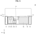
FIG. 5 is a rear view illustrating a first modification of the internal configuration of the display device according to the embodiment of the present disclosure; -
FIG. 6 is a cross-sectional view illustrating the first modification of the internal configuration of the display device according to an embodiment of the present disclosure; -
FIG. 7 is a rear view illustrating a second modification of an internal configuration of the display device according to an embodiment of the present disclosure; -
FIG. 8 is a rear view illustrating a third modification of an internal configuration of the display device according to an embodiment of the present disclosure; -
FIG. 9 is a cross-sectional view illustrating the third modification of the internal configuration of the display device according to an embodiment of the present disclosure; -
FIG. 10 is a rear view illustrating a fourth modification of an internal configuration of the display device according to an embodiment of the present disclosure; -
FIG. 11 is a cross-sectional view illustrating the fourth modification of the internal configuration of the display device according to an embodiment of the present disclosure; and -
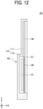
FIG. 12 is a cross-sectional view illustrating a fifth modification of an internal configuration of the display device according to an embodiment of the present disclosure. - The accompanying drawings are intended to depict embodiments of the present disclosure and should not be interpreted to limit the scope thereof. The accompanying drawings are not to be considered as drawn to scale unless explicitly noted. Also, identical or similar reference numerals designate identical or similar components throughout the several views.
- In describing embodiments illustrated in the drawings, specific terminology is employed for the sake of clarity. However, the disclosure of this specification is not intended to be limited to the specific terminology so selected and it is to be understood that each specific element includes all technical equivalents that have a similar function, operate in a similar manner, and achieve a similar result.
- Referring now to the drawings, embodiments of the present disclosure are described below. As used herein, the singular forms "a," "an," and "the" are intended to include the plural forms as well, unless the context clearly indicates otherwise.
- Descriptions are given of an example applicable to embodiments of the present disclosure.
-
FIG. 1 is an external perspective view illustrating a front side of adisplay device 100 according to an embodiment of the present disclosure.FIG. 2 is an external perspective view illustrating a rear side of thedisplay device 100 according to an embodiment of the present disclosure. - In the following description, a direction corresponding to the vertical direction of a
display 121 is referred to as an up-down direction (Z-axis direction). In addition, a direction corresponding to the horizontal direction of thedisplay 121 is referred to as a width direction or a left-right direction (Y-axis direction). Further, a direction corresponding to the depth direction of thedisplay 121 is referred to as a back-and-forth direction (X-axis direction). - Note that a direction (Y-axis positive direction) on the left side when viewed from the rear side (X-axis negative side) of the display is referred to as a left direction, and a direction (Y-axis negative direction) on the right side when viewed from the rear side (X-axis negative side) of the display is referred to as a right direction.
- The
display device 100 illustrated inFIGS. 1 and2 includes ascreen 121A of thedisplay 121 on the front face (face on the positive side of the X-axis). Thedisplay device 100 is connected to an external device (for example, a laptop computer or a smartphone) via acable 10 and can display various images (moving images or still images) transmitted from the external device via thecable 10 on thescreen 121A of thedisplay 121. In other words, thedisplay device 100 is a relatively thin display device having a built-in battery and portability. Thedisplay device 100 can be carried together with the external device and connected to the external device at the time of use. In other words, thedisplay device 100 can be used as an extended display device of an external device. - As illustrated in
FIGS. 1 and2 , thedisplay device 100 includes ahousing 110 that forms the outer shape of thedisplay device 100. Thehousing 110 is made of resin and has a hollow structure. Thehousing 110 includes athin portion 111 and athick portion 112. - The
thin portion 111 is a plate-shaped portion constituting the front side (Z-axis positive side) of thehousing 110. Thethin portion 111 has a horizontally long rectangular shape in a plan view from the front side (X-axis positive direction) or the rear side (X-axis negative direction). Thethin portion 111 is a portion having a relatively thin thickness in the depth direction (X-axis direction). Thethin portion 111 includes thedisplay 121. Arectangular opening 111A is formed in a front face (face on the positive side of the X-axis) of thethin portion 111, and ascreen 121A of thedisplay 121 exposes from the opening 111A. Thedisplay 121 is, for example, an organic electro-luminescence (EL) display or a liquid crystal display. - In the
thin portion 111, atouch sensor 122 is overlaid on thescreen 121A of thedisplay 121. Thetouch sensor 122 receives various input operations, for example, a selection operation and a handwriting input operation. As thetouch sensor 122, for example, a capacitive touch panel can be used. - The
thick portion 112 is a plate-shaped portion constituting the rear side (X-axis negative side) of thehousing 110 and is provided such that thethick portion 112 protrudes backward from a lower portion of the rear face ofthin portion 111. Thethick portion 112 is a portion having a relatively large thickness in the depth direction (X-axis direction). Thethick portion 112 has a horizontally long rectangular shape in a plan view from the rear side (X-axis negative direction). Thethick portion 112 has a vertical width and a horizontal width such that thethick portion 112 does not protrude from thethin portion 111 in a plan view from the rear side (X-axis negative direction). As illustrated inFIG. 4 , thethick portion 112 includes acontrol board 131 and abattery 133. As illustrated inFIG. 3 , aninterface portion 123 to which aconnector 11 of thecable 10 is connected is provided on the rear face of thethick portion 112. Theinterface portion 123 is, i.e., a "terminal" to which theconnector 11 of thecable 10 is connected. - A
switch 134 and aswitch 135 are provided on the left side (Y-axis positive side) of thethick portion 112. Theswitch 134 and theswitch 135 are, for example, a power button, a selection button, a confirmation button, and a return button. -
FIGS. 3A and 3B are a rear view and a side view, respectively, of thedisplay device 100 according to an embodiment of the present disclosure. - As illustrated in
FIG. 3A , arecess 113 is formed on the rear face of thethick portion 112 of thehousing 110. Therecess 113 is a portion recessed forward (X-axis positive direction) having a certain depth. In the example illustrated inFIG. 3A , therecess 113 has a rectangular shape in a plan view from the rear side, but the shape of therecess 113 is not limited to a rectangular shape. - As illustrated in
FIG. 3A , theinterface portions 123 expose in therecess 113 of thethick portion 112. In the example illustrated inFIG. 3A , theinterface portions 123 are disposed in therecess 113 to expose from aninner face 113A on the left side (Y-axis positive side) of therecess 113 of thethick portion 112. - Accordingly, in the
display device 100 according to the present embodiment as illustrated inFIG. 3A , theconnector 11 provided at one end of thecable 10 can be connected to theinterface portion 123 in a state of being disposed in therecess 113. - In other words, in the
display device 100 according to the present embodiment, theconnector 11 of thecable 10 can be connected to theinterface portion 123 without protruding from the side of thehousing 110. - As a result, according to the
display device 100 of the present embodiment, thedisplay device 100 and the external device can be arranged directly next to each other. - Further, since the
display device 100 of the present embodiment can prevent a sudden load from being applied to theconnector 11 of thecable 10, the risk of damaging theinterface portion 123 can be reduced. - The
cable 10 may be, for example, a universal serial bus (USB) cable and a highdefinition multimedia interface® (HDMI) cable. Theinterface portion 123 has a shape fitting into theconnector 11 of thecable 10. - The depth of the recess 113 (depth in the X-axis direction) is larger than any of the thickness of the
connector 11 and the outer diameter of thecable 10. Accordingly, in thedisplay device 100 according to the present embodiment as illustrated inFIG. 3B , the cable 10 (including the connector 11) in therecess 113 can be connected to theinterface portion 123 without protruding to the outer side (X-axis negative side) from the rear face of thethick portion 112. - As a result, the
display device 100 according to the present embodiment can prevent a sudden load from being applied to theconnector 11 of thecable 10 from the rear side of thethick portion 112. - As illustrated in
FIG. 3A , thethick portion 112 includes anoutlet 113B through which thecable 10 can be drawn out from therecess 113 to the upper side of thethick portion 112. To be specific, theoutlet 113B has a groove shape extending upward (in the Z-axis positive direction) from a corner on the upper right side (Z-axis positive side and Y-axis negative side) of therecess 113 and connecting to a space above thethick portion 112. The depth of theoutlet 113B (in the X-axis direction) is the same as the depth of the recess 113 (in the X-axis direction). - As a result, in the
display device 100 according to the present embodiment, thecable 10 can be drawn out from therecess 113 to the upper side of thethick portion 112 without protruding from the rear face of thethick portion 112 to the outside (X-axis negative side). - Further, as illustrated in
FIG. 3A , thethick portion 112 includes afastener 114 to fasten thecable 10 to theoutlet 113B. To be specific, both end portions of thefastener 114 in the left-right direction (Y-axis direction) can be fixed to thethick portion 112 by fitting in a state of straddling theoutlet 113B in the left-right direction (Y-axis direction). - As a result, according to the
display device 100 of the present embodiment, thecable 10 can be fastened to theoutlet 113B by thefastener 114 so that thecable 10 does not fall off from theoutlet 113B. In addition, according to thedisplay device 100 of the present embodiment, even in a case where a load such as being pulled by thecable 10 occurs, the load can be received by thefastener 114. As a result, a risk of damaging theinterface portion 123 can be reduced. - As illustrated in
FIGS. 3A and 3B , thethick portion 112 has anupper face 112A and can guide an arrangement path of thecable 10 drawn out from theoutlet 113B along anupper face 112A of thethick portion 112. - As a result, in the
display device 100 according to the present embodiment, thecable 10 drawn out from theoutlet 113B can be easily arranged on a predetermined arrangement path. - As illustrated in
FIGS. 3A and 3B , thethick portion 112 hasclamps 115 to hold thecable 10 whose arrangement path is guided by theupper face 112A of thethick portion 112. - As a result, the
display device 100 according to the present embodiment can hold thecable 10 pulled out from theoutlet 113B on the predetermined arrangement path. - In the example illustrated in
FIG. 3A , thethick portion 112 includes twoclamps 115 in each of the arrangement path of thecable 10 on the right side (Y-axis negative side) of theoutlet 113B and the arrangement path of thecable 10 on the left side (Y-axis positive side) of theoutlet 113B. - As a result, in the
display device 100 according to the present embodiment, thecable 10 can be held on the arrangement path by the twoclamps 115 in any of the case where the draw-out direction of thecable 10 is left (Y-axis positive direction) and the case where the draw-out direction of thecable 10 is right (Y-axis negative direction). - In the example illustrated in
FIG. 3A , on the rear face of thethick portion 112, theinterface portion 123 is disposed on the left side (Y-axis positive side) of the central portion in the left-right direction (Y-axis direction), while theoutlet 113B is disposed in the central portion in the left-right direction (Y-axis direction). - Accordingly, in the
display device 100 according to the present embodiment, thecable 10 connected to theinterface portion 123 can be easily bent and drawn out from theoutlet 113B (i.e., the center portion in the left-right direction (Y-axis direction)) to the upper side of thethick portion 112. - In addition, in the
display device 100 according to the present embodiment, the draw-out direction of thecable 10 from theoutlet 113B can be set to either the left direction (Y-axis positive direction) or the right direction (Y-axis negative direction). - As described above, in the
display device 100 according to the present embodiment, theoutlet 113B is disposed in the central portion in the right-left direction (Y-axis direction). As a result, the length of a portion of thecable 10 guided along the upper face of thethick portion 112 can be equal between the case where the draw-out direction of thecable 10 from theoutlet 113B is left (Y-axis positive direction) and the case where the draw-out direction is right (Y-axis negative direction). In other words, the length of the portion of thecable 10 drawn out from thehousing 110 to the outside can be equal. As a result, in thedisplay device 100 according to the present embodiment, the required length of thecable 10 can be set to a constant length regardless of whether an external device to be connected to thedisplay device 100 is arranged on the left side or the right side of thedisplay device 100. - In the example illustrated in
FIG. 3A , twointerface portions 123 are disposed side by side in the up-down direction (Z-axis direction) on the Y-axis positive side of theinner face 113A of therecess 113 of thethick portion 112. Accordingly, in thedisplay device 100 according to the present embodiment, twocables 10 can be connected in therecess 113. As a result, two external devices can be connected to thedisplay device 100 via the twocables 10. In the example illustrated inFIG. 3A , theoutlet 113B has a horizontal width (in the right-left direction) larger than twice the outside diameter of thecable 10 such that the twocables 10 can be drawn out side by side. - As illustrated in
FIG. 3A , thedisplay device 100 according to the present embodiment includes astand 136 in thethick portion 112. Thestand 136 can be stored in thethick portion 112. As illustrated inFIG. 3A , thestand 136 includesrotation shafts 136X at an upper end portion of thestand 136, and thestand 136 is provided to be rotatable about therotation shafts 136X. - The
stand 136 has a rectangular frame shape. On the other hand, astorage groove 112B having the same shape as thestand 136 is formed in thethick portion 112. As a result, thedisplay device 100 according to the present embodiment can store thestand 136 in thestorage groove 112B in a manner such that thestand 136 does not protrude from the rear face of thethick portion 112. - As illustrated in
FIGS. 1 and2 , in thedisplay device 100 according to the embodiment, thestand 136 is rotated from the stored state to the opened state, thus allowing thehousing 110 to stand on an installation surface. Thedisplay device 100 according to the present embodiment can adjust the opening angle of thestand 136 to adjust the inclination of thehousing 110 with respect to the installation surface. - The
rotation shafts 136X of thestand 136 are disposed below theupper face 112A of thethick portion 112. Accordingly, in thedisplay device 100 according to the present embodiment, the opening and closing operation of thestand 136 does not interfere with thecable 10 arranged along theupper face 112A of thethick portion 112. - As illustrated in
FIG. 3A , in a case where the direction in which thecable 10 is drawn out from theoutlet 113B is the right direction (Y-axis negative direction), the twoclamps 115 provided on the right side (Y-axis negative side) of theoutlet 113B hold thecable 10. However, the twoclamps 115 provided on the left side (Y-axis positive side) of theoutlet 113B are in a free state. - Then, in the
display device 100 according to the present embodiment, thecable 10 is folded back in the vicinity of the end portion on the right side (Y-axis negative side) of thehousing 110. Thus, the other end portion side of thecable 10 can be held by theclamps 115 provided on the left side (Y-axis positive side) of theoutlet 113B. - As a result, when the
display device 100 according to the present embodiment is not used (e.g., during transportation or storage), thedisplay device 100 can hold thecable 10 and bring thecable 10 into the stored state without protruding thecable 10 from thehousing 110. - In the
display device 100 according to the present embodiment, theconnector 11 at the one end of thecable 10 is connected to theinterface portion 123 without protruding rearward (X-axis negative direction) from therecess 113 of thethick portion 112. Accordingly, a load is less likely to be applied to theconnector 11 at the one end even when thedisplay device 100 is not in use (during transportation or storage). As a result, thedisplay device 100 according to the present embodiment can bring thecable 10 into the stored state with theconnector 11 at the one end being connected to theinterface portion 123. - In the
display device 100 according to the present embodiment, the difference between the thickness of thethick portion 112 and the thickness of thethin portion 111 is larger than the outer diameter of thecable 10. As a result, in thedisplay device 100 according to the present embodiment, the portion of thecable 10 drawn out from theoutlet 113B can be arranged on the rear face of thethin portion 111 on the upper side of thethick portion 112 such that thecable 10 does not protrude to the outer side (X-axis negative side) from the rear face of thethick portion 112. -
FIG. 4 is a rear view illustrating an internal configuration of thedisplay device 100 according to an embodiment of the present embodiment. - As illustrated in
FIG. 4 , thethick portion 112 of thehousing 110 is divided by thestorage groove 112B into a left grip portion R1, an intermediate portion R3, and a right grip portion R2. - To be specific, the
storage groove 112B includes a first storage portion 112Ba and a second storage portion 112Bc. The first storage portion 112Ba is elongated in the vertical direction (Z-axis direction) and stores the left frame portion of thestand 136. The second storage portion 112Bc is elongated in the vertical direction (Z-axis direction) and stores the right frame portion of thestand 136. - The left grip portion R1 of the
thick portion 112 is a portion of thestorage groove 112B on the left side (Y-axis positive side) of the first storage portion 112Ba. The left grip portion R1 has a certain width from the left side face of thehousing 110. The left grip portion R1 is a portion gripped by the right hand of a user when the user grips thehousing 110 with both hands from the front face side (X-axis positive side) of thehousing 110. The left grip portion R1 has a hollow structure. The inner space of the left grip portion R1 is not connected to the inner space of the intermediate portion R3. - The right grip portion R2 of the
thick portion 112 is a portion of thestorage groove 112B on the right side (Y-axis negative side) of the second storage portion 112Bc. The right grip portion R2 has a certain width from the right side face of thehousing 110. The right grip portion R2 is a portion gripped by the left hand of the user when the user grips thehousing 110 with both hands from the front face side (X-axis positive side) of thehousing 110. The right grip portion R2 has a hollow structure. The inner space of the right grip portion R2 is not connected to the inner space of the intermediate portion R3. - The intermediate portion R3 of the
thick portion 112 is a portion between the first storage portion 112Ba and the second storage portion 112Bc of thestorage groove 112B. The intermediate portion R3 has a hollow structure. - As illustrated in
FIG. 4 , thecontrol board 131 and thebattery 133 are disposed inside thethick portion 112. - The
control board 131 is connected to theinterface portion 123, and various electronic components are mounted on thecontrol board 131 to construct a control circuit that controls the operation of thedisplay device 100. In other words, thecontrol board 131 is configured to control thedisplay device 100. - The
battery 133 supplies electric power to drive thedisplay device 100. Various rechargeable secondary batteries (for example, a lithium-ion battery and a lithium polymer battery) are used as thebattery 133. Thedisplay device 100 can be supplied with power from an external device via thecable 10 and theinterface portion 123 to charge thebattery 133. - As illustrated in
FIG. 4 , thecontrol board 131 and thebattery 133, which are high-temperature components, are disposed inside the intermediate portion R3. In other words, in a first example illustrated inFIG. 4 , thecontrol board 131 and thebattery 133, which are high-temperature components, are disposed neither inside the left grip portion R1 nor inside the right grip portion R2. In the first example illustrated inFIG. 4 , no other high-temperature components are disposed inside the left grip portion R1 and the right grip portion R2. - As a result, the
display device 100 according to the present embodiment can prevent the left grip portion R1 and the right grip portion R2, which are touched with a user's hands, from reaching high temperature when the user grips thehousing 110 with both hands from the front face side (X-axis positive side) of thehousing 110. - In addition, since the
display device 100 according to the present embodiment does not actively release the heat generated from thecontrol board 131 and thebattery 133 to thedisplay 121, thedisplay device 100 can prevent thedisplay 121 from being high in temperature. - In particular, the
display device 100 according to the present embodiment includes thestand 136 that has a frame shape, is rotatable, and can be stored in thestorage groove 112B formed on the rear face of thethick portion 112 of thehousing 110. Thethick portion 112 of thehousing 110 is divided by thestorage groove 112B into the left grip portion R1, the right grip portion R2, and the intermediate portion R1 provided between the left grip portion R2 and the right grip portion R3. - In other words, in the
display device 100 according to the present embodiment, thestand 136 is disposed to surround theinterface portion 123, and the left grip portion R1 and the right grip portion R2 are disposed on the outer side of thedisplay device 100 than thestand 136. - Accordingly, in the
display device 100 according to the present embodiment, the left grip portion R1 and the right grip portion R1 can be spatially separated from the intermediate portion R3 by thestorage groove 112B. Such a configuration can reduce the transmission of heat generated from the high-temperature components in the intermediate portion R3 to the left grip portion R1 and the right grip portion R2. - The
display device 100 according to the present embodiment can also prevent thestand 136 from interfering with the user's hands gripping the left grip portion R1 and the right grip portion R2. - It is preferable that each of the left grip portion R1 and the right grip portion R2 has a width equal to or larger than a range in which the user's hand touches. For example, in the present embodiment, each of the left grip portion R1 and the right grip portion R2 has a width equal to or greater than a length from the finger tip to the second joint of the user in view of the situation that a portion from the finger tip to the second joint of the user contacts the left grip portion R1 or the right grip portion R2 when the user grips the
housing 110 with both hands from the front face side (X-axis positive side) of thehousing 110. -
FIG. 5 is a rear view illustrating a first modification of an internal configuration of thedisplay device 100 according to an embodiment of the present disclosure.FIG. 6 is a cross-sectional view illustrating the first modification of the internal configuration of thedisplay device 100 according to an embodiment of the present disclosure. - In the example illustrated in
FIGS. 5 and6 ,electronic components - In the example illustrated in
FIGS. 5 and6 , thedisplay device 100 according to the present embodiment includes a thermalconductive sheet 137 attached to the inner face of thethick portion 112 of thehousing 110 at a position facing the control board 131 (high-temperature component). As the thermalconductive sheet 137, a sheet member made of a material having high thermal conductivity (for example, aluminum foil) is used. - Accordingly, in the
display device 100 according to the present embodiment, heat generated from theelectronic components control board 131 is transmitted to the overall thermalconductive sheet 137. As a result, thedisplay device 100 can prevent the temperature of the intermediate portion R3 of thethick portion 112 of thehousing 110 from being locally increased. Since the user's hand may touch even the intermediate portion R3, the configuration described above is useful. -
FIG. 7 is a rear view illustrating a second modification of an internal configuration of thedisplay device 100 according to an embodiment of the present disclosure. - In the example illustrated in
FIG. 7 , the thermalconductive sheet 137 is attached to a wide region including an area facing the control board 131 (high-temperature component) and an area facing the battery 133 (high-temperature component) on the inner face of thethick portion 112 of thehousing 110. - Accordingly, in the
display device 100 according to the present embodiment, heat generated from thecontrol board 131 and heat generated from thebattery 133 are transmitted to the overall thermalconductive sheet 137 in a wider range than in the first modification. Thus, thedisplay device 100 can prevent the temperature of the intermediate portion R3 of thethick portion 112 of thehousing 110 from being locally increased. -
FIG. 8 is a rear view illustrating a third modification of an internal configuration of thedisplay device 100 according to an embodiment of the present disclosure.FIG. 9 is a cross-sectional view illustrating the third modification of the internal configuration of thedisplay device 100 according to an embodiment of the present disclosure. - In the example illustrated in
FIGS. 8 and9 , thedisplay device 100 according to the present embodiment includes aheat transfer member 138 disposed between the rear face of thedisplay 121 and the rear face of the housing 110 (excluding the left grip portion R1 and the right grip portion R2) facing each other. As theheat transfer member 138, a sheet member made of a material having high thermal conductivity (for example, aluminum foil or heat transfer rubber) is used. - Accordingly, in the
display device 100 according to the present embodiment, heat generated from thedisplay 121 is released to the rear face of the housing 110 (except for the left grip portion R1 and the right grip portion R2) through theheat transfer member 138. As a result, thedisplay device 100 can prevent thedisplay 121 from reaching high temperature. Since thedisplay 121 may be touched by the user's hand for touch operation, the configuration described above is useful. -
FIG. 10 is a rear view illustrating a fourth modification of an internal configuration of thedisplay device 100 according to an embodiment of the present disclosure.FIG. 11 is a cross-sectional view illustrating the fourth modification of the internal configuration of thedisplay device 100 according to an embodiment of the present disclosure. - In the example illustrated in
FIGS. 10 and11 , the rear face of thedisplay 121 and each of the control board 131 (high-temperature component) and the battery 133 (high-temperature component) are opposed to each other. Thedisplay device 100 according to the present embodiment includes a sheet-shapedheat insulator 139 disposed between the rear face of thedisplay 121 and each of thecontrol board 131 and thebattery 133. - Accordingly, the
display device 100 according to the present embodiment can reduce the transmission of heat generated from thecontrol board 131 and the heat generated from thebattery 133 to thedisplay 121. As a result, thedisplay device 100 can prevent thedisplay 121 from reaching high temperature. -
FIG. 12 is a cross-sectional view illustrating a fifth modification of an internal configuration of thedisplay device 100 according to an embodiment of the present disclosure. - In the example illustrated in
FIG. 12 , the rear face of thedisplay 121 and each of the control board 131 (high-temperature component) and the battery 133 (high-temperature component) are opposed to each other, similarly to the fourth modification. Thedisplay device 100 according to the present embodiment includes a sheet-shapedheat insulator 139 disposed between the rear face of thedisplay 121 and each of thecontrol board 131 and thebattery 133. - In the example illustrated in
FIG. 12 , thedisplay device 100 according to present the embodiment further includes theheat transfer member 138 disposed between the rear face of thedisplay 121 and theheat insulator 139, which are opposed to each other. - Accordingly, the
display device 100 according to the present embodiment can reduce the transmission of heat generated from thecontrol board 131 and the heat generated from thebattery 133 to thedisplay 121. As a result, thedisplay device 100 can prevent thedisplay 121 from reaching high temperature. - In addition, the
display device 100 according to the present embodiment can release the heat generated from thedisplay 121 to theheat transfer member 138. As a result, thedisplay device 100 can prevent thedisplay 121 from reaching high temperature. - Although some embodiments of the invention have been described in detail above, the present disclosure is not limited to such specific embodiments, and various modifications and changes can be made within the scope of the gist of the invention described in the claims.
- No component may be provided inside the left grip portion R1 and the right grip portion R2, or a component (for example, a speaker or an antenna unit) that does not reach a high temperature may be provided inside the left grip portion R1 and the right grip portion R2.
- The left grip portion R1 and the right grip portion R2 may be configured such that the user can easily recognize the left grip portion R1 and the right grip portion R2. For example, the left grip portion R1 and the right grip portion R2 may have a shape to which a hand of the user is placed. For example, the left grip portion R1 and the right grip portion R2 may be indicated by a color different from the color of the intermediate portion R3.
Claims (8)
- A display device (100) comprising:a housing (110) including grip portions (R1, R2) to be gripped at a right end portion and a left end portion of the housing (110) in a horizontal direction;a screen (121A) on a front face of the housing (110); anda control board (131) configured to control the display device (100) and disposed at a position at which the control board (131) does not overlap with the grip portions (R1, R2) in a direction orthogonal to the screen (121A).
- The display device (100) according to claim 1, further comprising a battery (133) disposed at a position at which the battery does not overlap with the grip portions (R1, R2) in the direction orthogonal to the screen (121A).
- The display device (100) according to claim 1 or 2, wherein the housing (110) has a rectangular shape in a plan view from a front side or a rear side of the display device (100).
- The display device (100) according to any one of claims 1 to 3, further comprising a thermal conductive sheet (137) attached to an inner face of the housing (110) at a position at which the inner face faces the control board (131) or the battery (133).
- The display device (100) according to any one of claims 1 to 4, further comprising a heat transfer member (138) disposed between a rear face of the screen (121A) and a rear face of the housing (110) that are opposed to each other.
- The display device (100) according to any one of claims 1 to 4, further comprising a heat transfer member (138) disposed between a rear face of the screen (121A) and one of the control board (131) and the battery (133).
- The display device (100) according to any one of claims 1 to 6, further comprising:a storage groove (112B) on a rear face of the housing (110); anda stand (136) being rotatable and having a rectangular frame shape, the stand (136) configured to be stored in the storage groove (112B),wherein the grip portions (R1, R2) are a left grip portion (R1) and a right grip portion (R2),wherein the housing (110) is divided by the storage groove (112B) into the left grip portion (R1), the right grip portion (R2), and an intermediate portion (R3) disposed between the left grip portion (R1) and the right grip portion (R2).
- The display device (100) according to any one of claims 1 to 6, further comprising:a terminal (123) to which a cable (10) is to be connected; anda stand (136) surrounding the terminal (123),wherein the grip portions (R1, R2) are disposed at positions outside the stand in the display device (100).
Applications Claiming Priority (1)
| Application Number | Priority Date | Filing Date | Title |
|---|---|---|---|
| JP2022032712A JP2023128391A (en) | 2022-03-03 | 2022-03-03 | display device |
Publications (2)
| Publication Number | Publication Date |
|---|---|
| EP4242789A1 true EP4242789A1 (en) | 2023-09-13 |
| EP4242789B1 EP4242789B1 (en) | 2026-04-01 |
Family
ID=85175898
Family Applications (1)
| Application Number | Title | Priority Date | Filing Date |
|---|---|---|---|
| EP23155087.2A Active EP4242789B1 (en) | 2022-03-03 | 2023-02-06 | Display device |
Country Status (3)
| Country | Link |
|---|---|
| US (1) | US20230280794A1 (en) |
| EP (1) | EP4242789B1 (en) |
| JP (1) | JP2023128391A (en) |
Families Citing this family (2)
| Publication number | Priority date | Publication date | Assignee | Title |
|---|---|---|---|---|
| JP2024040823A (en) * | 2022-09-13 | 2024-03-26 | 株式会社リコー | display device |
| JP2024050041A (en) | 2022-09-29 | 2024-04-10 | 株式会社リコー | Display device, display control method, program, and display system |
Citations (4)
| Publication number | Priority date | Publication date | Assignee | Title |
|---|---|---|---|---|
| US20010048586A1 (en) * | 2000-05-24 | 2001-12-06 | Ryuichi Itou | Information processing equipment |
| JP2006032615A (en) | 2004-07-15 | 2006-02-02 | Nec Infrontia Corp | Electronic apparatus |
| US20070297124A1 (en) * | 2006-05-15 | 2007-12-27 | Sony Corporation | Information processing device |
| WO2021165366A1 (en) * | 2020-02-21 | 2021-08-26 | Ambu A/S | Portable monitor |
Family Cites Families (4)
| Publication number | Priority date | Publication date | Assignee | Title |
|---|---|---|---|---|
| JP2010081280A (en) * | 2008-09-26 | 2010-04-08 | Hitachi Ltd | Video display apparatus |
| JP2011239170A (en) * | 2010-05-11 | 2011-11-24 | Panasonic Corp | Display device |
| JP2010244569A (en) * | 2010-06-19 | 2010-10-28 | Shunsuke Yoshida | Operation function of notebook computer with handle |
| JP4902015B2 (en) * | 2011-10-07 | 2012-03-21 | 株式会社東芝 | Television receiver and electronic device |
-
2022
- 2022-03-03 JP JP2022032712A patent/JP2023128391A/en active Pending
-
2023
- 2023-01-17 US US18/155,298 patent/US20230280794A1/en active Pending
- 2023-02-06 EP EP23155087.2A patent/EP4242789B1/en active Active
Patent Citations (5)
| Publication number | Priority date | Publication date | Assignee | Title |
|---|---|---|---|---|
| US20010048586A1 (en) * | 2000-05-24 | 2001-12-06 | Ryuichi Itou | Information processing equipment |
| JP2006032615A (en) | 2004-07-15 | 2006-02-02 | Nec Infrontia Corp | Electronic apparatus |
| JP4421963B2 (en) | 2004-07-15 | 2010-02-24 | Necインフロンティア株式会社 | Electronics |
| US20070297124A1 (en) * | 2006-05-15 | 2007-12-27 | Sony Corporation | Information processing device |
| WO2021165366A1 (en) * | 2020-02-21 | 2021-08-26 | Ambu A/S | Portable monitor |
Also Published As
| Publication number | Publication date |
|---|---|
| EP4242789B1 (en) | 2026-04-01 |
| US20230280794A1 (en) | 2023-09-07 |
| JP2023128391A (en) | 2023-09-14 |
Similar Documents
| Publication | Publication Date | Title |
|---|---|---|
| US12242311B2 (en) | Display device | |
| US12560975B2 (en) | Display device | |
| EP4242789B1 (en) | Display device | |
| US7852625B2 (en) | Information processing apparatus | |
| US9192061B2 (en) | Electronic device | |
| US9568949B2 (en) | Electronic apparatus | |
| JP5895509B2 (en) | Electronics | |
| US20140340829A1 (en) | Electronic device | |
| JP2014232849A (en) | Stand for electronic apparatus, and electronic apparatus | |
| US8238119B2 (en) | Electronic device | |
| CN107959735A (en) | Electronic equipment and its manufacture method including battery module | |
| US11075492B2 (en) | Adapter and electronic system having the same | |
| US20140211108A1 (en) | Electronic Device and Stand for Electronic Device | |
| KR20190138972A (en) | Battery with electrode-tabs and electronic device therewith | |
| JP4772907B2 (en) | Electronic equipment and battery pack | |
| JP2020101754A (en) | Imaging device | |
| US20070153461A1 (en) | Portable computer system | |
| US20150305173A1 (en) | Electronic device | |
| EP4676175A1 (en) | Electronic device | |
| US7986513B2 (en) | Battery holding mechanism and electronic device | |
| US7192305B2 (en) | Electronic apparatus including restraint member receiving plug coupled to connector | |
| JP2001102018A (en) | Battery for electronic equipment | |
| CN105304380B (en) | Input unit and electronic equipment | |
| US7957136B2 (en) | Electronic apparatus | |
| US20250372790A1 (en) | Battery exchange system |
Legal Events
| Date | Code | Title | Description |
|---|---|---|---|
| PUAI | Public reference made under article 153(3) epc to a published international application that has entered the european phase |
Free format text: ORIGINAL CODE: 0009012 |
|
| STAA | Information on the status of an ep patent application or granted ep patent |
Free format text: STATUS: REQUEST FOR EXAMINATION WAS MADE |
|
| 17P | Request for examination filed |
Effective date: 20230206 |
|
| AK | Designated contracting states |
Kind code of ref document: A1 Designated state(s): AL AT BE BG CH CY CZ DE DK EE ES FI FR GB GR HR HU IE IS IT LI LT LU LV MC ME MK MT NL NO PL PT RO RS SE SI SK SM TR |
|
| GRAP | Despatch of communication of intention to grant a patent |
Free format text: ORIGINAL CODE: EPIDOSNIGR1 |
|
| STAA | Information on the status of an ep patent application or granted ep patent |
Free format text: STATUS: GRANT OF PATENT IS INTENDED |
|
| INTG | Intention to grant announced |
Effective date: 20250909 |
|
| GRAS | Grant fee paid |
Free format text: ORIGINAL CODE: EPIDOSNIGR3 |
|
| P01 | Opt-out of the competence of the unified patent court (upc) registered |
Free format text: CASE NUMBER: UPC_APP_0019568_4242789/2025 Effective date: 20251229 |
|
| GRAA | (expected) grant |
Free format text: ORIGINAL CODE: 0009210 |
|
| STAA | Information on the status of an ep patent application or granted ep patent |
Free format text: STATUS: THE PATENT HAS BEEN GRANTED |
|
| AK | Designated contracting states |
Kind code of ref document: B1 Designated state(s): AL AT BE BG CH CY CZ DE DK EE ES FI FR GB GR HR HU IE IS IT LI LT LU LV MC ME MK MT NL NO PL PT RO RS SE SI SK SM TR |
|
| REG | Reference to a national code |
Ref country code: CH Ref legal event code: F10 Free format text: ST27 STATUS EVENT CODE: U-0-0-F10-F00 (AS PROVIDED BY THE NATIONAL OFFICE) Effective date: 20260401 Ref country code: GB Ref legal event code: FG4D |
|
| REG | Reference to a national code |
Ref country code: IE Ref legal event code: FG4D |
|
| REG | Reference to a national code |
Ref country code: DE Ref legal event code: R096 Ref document number: 602023014260 Country of ref document: DE |