EP4242714A2 - Optical system for use with a vacuum chamber and associated method - Google Patents
Optical system for use with a vacuum chamber and associated method Download PDFInfo
- Publication number
- EP4242714A2 EP4242714A2 EP23182663.7A EP23182663A EP4242714A2 EP 4242714 A2 EP4242714 A2 EP 4242714A2 EP 23182663 A EP23182663 A EP 23182663A EP 4242714 A2 EP4242714 A2 EP 4242714A2
- Authority
- EP
- European Patent Office
- Prior art keywords
- flexure
- frame
- optical assembly
- coupled
- actuators
- Prior art date
- Legal status (The legal status is an assumption and is not a legal conclusion. Google has not performed a legal analysis and makes no representation as to the accuracy of the status listed.)
- Granted
Links
Images


Classifications
-
- H—ELECTRICITY
- H01—ELECTRIC ELEMENTS
- H01S—DEVICES USING THE PROCESS OF LIGHT AMPLIFICATION BY STIMULATED EMISSION OF RADIATION [LASER] TO AMPLIFY OR GENERATE LIGHT; DEVICES USING STIMULATED EMISSION OF ELECTROMAGNETIC RADIATION IN WAVE RANGES OTHER THAN OPTICAL
- H01S3/00—Lasers, i.e. devices using stimulated emission of electromagnetic radiation in the infrared, visible or ultraviolet wave range
- H01S3/005—Optical devices external to the laser cavity, specially adapted for lasers, e.g. for homogenisation of the beam or for manipulating laser pulses, e.g. pulse shaping
-
- G—PHYSICS
- G02—OPTICS
- G02B—OPTICAL ELEMENTS, SYSTEMS OR APPARATUS
- G02B7/00—Mountings, adjusting means, or light-tight connections, for optical elements
- G02B7/02—Mountings, adjusting means, or light-tight connections, for optical elements for lenses
- G02B7/023—Mountings, adjusting means, or light-tight connections, for optical elements for lenses permitting adjustment
-
- G—PHYSICS
- G02—OPTICS
- G02B—OPTICAL ELEMENTS, SYSTEMS OR APPARATUS
- G02B6/00—Light guides; Structural details of arrangements comprising light guides and other optical elements, e.g. couplings
- G02B6/24—Coupling light guides
- G02B6/42—Coupling light guides with opto-electronic elements
- G02B6/4296—Coupling light guides with opto-electronic elements coupling with sources of high radiant energy, e.g. high power lasers, high temperature light sources
-
- G—PHYSICS
- G02—OPTICS
- G02B—OPTICAL ELEMENTS, SYSTEMS OR APPARATUS
- G02B7/00—Mountings, adjusting means, or light-tight connections, for optical elements
- G02B7/003—Alignment of optical elements
- G02B7/005—Motorised alignment
Definitions
- the present invention relates to the field of optical assemblies, and, more particularly, to an optical system for use with a vacuum chamber and associated method.
- Ion trap quantum computing uses highly precise alignment of the final "atom imager" objective lens. For example, this may include thirty-two telecentric beams targeting an array of thirty-two individual atoms. The location in all three axes (x, y, z) is desirable controlled to within ⁇ 50um, for example. In addition, the beam angle in the x and y direction (pitch and yaw) may be controlled within 10mrad.
- An example for a lens positioner with five degrees of freedom is disclosed in the document US 4 099 852 A .
- An example for an optical system with an adjustment stage is disclosed in the document US 2021 / 055 501 A1 .
- an example for a precision retroreflector positioning apparatus is disclosed in the document US 2006 001 886 A1 .
- An optical system for use with a vacuum chamber may include a target to be positioned within the vacuum chamber, a laser source, and an optical assembly to be positioned within the vacuum chamber between the target and the laser source.
- the optical assembly may include a housing, a frame, a lens carried by the frame, and a plurality of spiral flexures each having a respective proximal end coupled to the frame.
- the optical assembly may include a plurality of flexure actuators, where each flexure actuator is coupled between the housing and a distal end of a respective spiral flexure.
- the optical assembly may comprise a respective threaded flexure tube coupled to a distal end of each of the plurality of spiral flexures.
- Each flexure actuator may comprise a motor having a rotatable threaded output shaft coupled to a respective threaded flexure tube.
- the flexure actuators may be carried within the housing.
- the optical assembly may also comprise a plurality of translation actuators coupled between the housing and the frame.
- the flexure actuators and the translation actuators may be configured to provide five degrees of freedom (DOF) movement for adjustment of the lens.
- DOF degrees of freedom
- the frame may include a pair of elongate passageways orthogonal to one another.
- Each translation actuator may comprise a motor having an eccentric output shaft received within a respective elongate passageway. Similar to the flexure actuators, the plurality of translation actuators may also be carried within the housing.
- the frame may have a rectangular shape defining four corners, for example.
- the proximal end of each spiral flexure is coupled to the frame at a respective corner.
- the target may comprise an atom trap.
- the target may comprise a semiconductor mask.
- the optical assembly may be used in other applications as well.
- a method aspect is directed to a method of steering a laser beam from a laser source to a target within a vacuum chamber.
- the method may include operating a plurality of flexure actuators of an optical assembly within the vacuum chamber between the target and the laser source.
- the optical assembly may comprise a housing, a frame, a lens carried by the frame, and a plurality of spiral flexures each having a respective proximal end coupled to the frame.
- the optical assembly also comprises the plurality of flexure actuators, with each flexure actuator coupled between the housing and a distal end of a respective spiral flexure.
- Ion trap quantum computing requires highly precise alignment of the final "atom imager" objective lens of an optical assembly. There is a desire to move away from re-entrant windows in large vacuum chambers and toward more compact, highly integrated designs having the objective lens inside the vacuum chamber. Thus, minimizing chamber size may be critical to system performance.
- the optical assembly may need to be as small as possible as operation inside the vacuum chamber would typically use remote operation of the lens mount adjustments.
- an optical system is generally designated 102 and is part of a quantum computer 100.
- the optical system 102 includes an optical assembly 104, a laser source and associated acousto-optic modulator (AOM) 106, and a target in the form of atoms (e.g. ions) 108 within an atom trap 110.
- An objective lens 114 is aligned between the laser source 106 and the target 108.
- the optical system 102 satisfies tightly controlled telecentricity, distortion, and spot size requirements.
- the optical system 102 may also be adapted to fiber-coupling for acousto-optic (AO) devices.
- AO acousto-optic
- the ability to provide fiber-coupled acousto-optic modulators (AOMs) may become increasingly important as the quantum computing industry grows.
- optical system 102 allows operation over a large spectrum.
- the optical system 102 may accordingly provide advantages with respect to numerous different types of targets.
- the optical system 102 may provide five degrees of freedom of movement for adjustment, and comprises a parallel flexure system for final objective lens mounting as described in more detail below.
- the z-axis is defined in the direction of the laser source 106 to the target 108.
- the laser source 106 generates a plurality of laser beams 112 that are aimed through the lens 114 to the target 108.
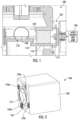
- the optical assembly 104 includes a housing 120, a frame 122, the lens 114 carried by the frame 122, and a plurality of spiral flexures 124a, 124b, 124c, 124d, each having a respective proximal end coupled to the frame 122 as shown in FIG. 2 .
- the spiral flexures 124a, 124b, 124c, 124d operate both as pseudo-spherical joints and as prismatic joints. Accordingly, the five degrees of freedom of movement are advantageously managed in a single stage, as opposed to serially in stacked stages, for example.
- the optical assembly 104 may be cube shaped and have a dimension of approximately 20 millimeters on each side.
- the optical assembly 104 is space-efficient and may be more tightly integrated with the vacuum chamber 116 than current approaches and can also be adapted to fiber-coupling of acousto-optic devices.
- spiral flexures 124a, 124b, 124c, 124d have a high effective aspect ratio, allowing for a large adjustment range of ⁇ x, ⁇ y, ⁇ z: ⁇ .010" (254 ⁇ m) and ⁇ x, ⁇ y: ⁇ 5°.
- a precision of adjustment of the optical assembly 104 is driven in part by the controls design.
- the optical assembly 104 features high precision and includes kinematically adjustments for each degree of freedom.
- the optical assembly 104 may include a plurality of flexure actuators 126a, 126b, 126c, 126d, where each flexure actuator is coupled between the housing 120 and a distal end of a respective spiral flexure.
- Each of the flexure actuators 126a, 126b, 126c, 126d may comprise a respective threaded flexure tube 128a, 128b, 128c, 128d coupled to a distal end of each of the plurality of spiral flexures.
- Each flexure actuator may also comprise a motor 130a, 130b, 130c, 130d having a rotatable threaded output shaft 132a, 132b, 132c, 132d coupled to a respective threaded flexure tube.
- the flexure actuators may be carried within the housing 120 as shown in the illustrated embodiment.
- the optical assembly 104 may also comprise a plurality of translation actuators 134a, 134b coupled between the housing 120 and the frame 122.
- the flexure actuators 126a, 126b, 126c, 126d and the translation actuators 134a, 134b are configured to provide the five degrees of freedom (DOF) movement for adjustment of the lens 114.
- DOF degrees of freedom
- the frame 122 may include a pair of elongate passageways 136a, 136b orthogonal to one another.
- Each translation actuator 134a, 134b may comprise a respective motor 140a, 140b having an eccentric output shaft 138a, 138b received within a respective elongate passageway 136a, 136b. Similar to the flexure actuators, the plurality of translation actuators 134a, 134b may also be carried within the housing 120.
- the frame 122 may have a rectangular shape defining four corners, for example. In this embodiment, the distal end of each of the spiral flexures 124a, 124b, 124c, 124d is coupled to the frame 122 at a respective corner.
- the elongate passageway 136a is configured to engage the eccentric output shaft 138a to shift the frame 122 in the directions 142a, 142b along the x-axis.
- the frame 122 is configured to move in the direction 142a as the eccentric output shaft 138a rotates counter-clockwise.
- the frame is configured to move in the direction 142b as the eccentric output shaft 138b rotates in the opposing clockwise direction.
- the frame 122 can similarly be adjusted along the y-axis.
- the eccentric output shaft 138 is offset from the center of the translation actuator 134a. Accordingly, the eccentric output shaft 138 is configured to move in one of the directions 142a, 142b and consequently moves the frame 122 and lens 114 in the desired direction as the motor 140a rotates.
- the spiral flexure 124a is also shown in a partial cross-sectional view in FIG. 5 .
- the respective corner of the frame 122 is raised or lowered dependent on the direction the threaded output shaft 132a is rotated by the motor 130a.
- the threaded flexure tube 128a rides upwards on the threaded output shaft 132a and away from the housing 122 as the threaded output shaft 132a is rotated in the counter-clockwise direction.
- the threaded flexure tube 128a rides down on the threaded output shaft 132a and towards the housing 122.
- the frame 122 is illustrated in FIG. 6 without the lens 114 or the spiral or translation actuators. As explained above, the frame 122 combines five degrees of freedom of movement into one stage. The focus of the lens 114 is adjusted by actuating one or more of the spiral flexures 124a, 124b, 124c, 124d. For example, as spiral flexure 124c is raised as illustrated in FIG. 7 , the frame 122 moves accordingly to adjust the focus of the lens 114. As those of ordinary skill in the art can appreciate, the frame 122 and consequently the lens 114 can be adjusted in the ⁇ z, ⁇ x, ⁇ y directions using the spiral flexures 124a, 124b, 124c, 124d alone or in combination with each other.
- the alignment of the lens 114 would require three to five stages in series to achieve the alignment of the lens 114.
- the frame 122 achieves synergistic travel and moves similar to a Gough-Stewart platform discussed above. Linearity is driven by force balance among the spiral flexures, not kinematics, and having a relatively high specific stiffness (stiffness per unit mass).
- the spiral flexures 124a, 124b, 124c, 124d allow for relatively large adjustment range in both translation and rotation while efficiently distributing stress.
- the spiral flexures 124a, 124b, 124c, 124d have a unique aspect ratio and may desirably have a specific stiffness due to being almost a full diameter in thickness.
- the optical system 102' may be used in an application where the target comprises a semiconductor mask 108'.
- the laser source 106' is directed to the semiconductor mask 108' with the optical lens assembly 104' therebetween.
- the method may include operating a plurality of flexure actuators of an optical assembly within the vacuum chamber between the target and the laser source.
- the optical assembly may comprise a housing, a frame, a lens carried by the frame, and a plurality of spiral flexures each having a respective proximal end coupled to the frame.
- the optical assembly may also have a plurality of flexure actuators with each flexure actuator coupled between the housing and a distal end of a respective spiral flexure.
- the optical assembly may include a plurality of translation actuators where the flexure actuators and the translation actuators provide five degrees of freedom (DOF) of movement for adjustment of the lens.
- DOF degrees of freedom
- the method 200 includes operating the plurality of spiral flexure actuators of the optical assembly to adjust an angle of the lens, at Block 204, where a respective threaded flexure tube is coupled to a distal end of each of the plurality of spiral flexures, and each flexure actuator comprises a motor having a rotatable threaded output shaft coupled to a respective threaded flexure tube.
- the method includes operating a plurality of translation actuators of the optical assembly to adjust a translation of the lens, where each translation actuator comprises a motor having an eccentric output shaft received within a respective elongate passageway of the frame carrying the lens. The method ends at Block 208.
- an optical assembly to be used between a target positioned within a vacuum chamber and a laser source comprises: a housing; a frame; a lens carried by the frame; a plurality of spiral flexures each having a respective proximal end coupled to the frame; and a plurality of flexure actuators, each flexure actuator coupled between the housing and a distal end of a respective spiral flexure.
- the optical assembly may comprise a respective threaded flexure tube coupled to a distal end of each of the plurality of spiral flexures; and wherein each flexure actuator comprises a motor having a rotatable threaded output shaft coupled to a respective threaded flexure tube.
- the plurality of flexure actuators can be carried within the housing.
- the optical assembly may comprise a plurality of translation actuators coupled between the housing and the frame.
- the plurality of flexure actuators and the plurality of translation actuators can be configured to provide five degrees of freedom (DOF) of movement for adjustment of the lens.
- DOF degrees of freedom
- the frame can include a pair of elongate passageways orthogonal to one another.
- Each translation actuator can comprise a motor having an eccentric output shaft received within a respective elongate passageway.
- the plurality of translation actuators can be carried within the housing.
- the frame may have a rectangular shape defining four corners.
- the proximal end of each spiral flexure can be coupled to the frame at a respective corner.
- a method of steering a laser beam from a laser source to a target within a vacuum chamber comprises: operating a plurality of flexure actuators of an optical assembly within the vacuum chamber between the target and the laser source, the optical assembly comprising a housing, a frame, a lens carried by the frame, a plurality of spiral flexures each having a respective proximal end coupled to the frame, and the plurality of flexure actuators, each flexure actuator coupled between the housing and a distal end of a respective spiral flexure.
- the optical assembly can comprise a respective threaded flexure tube coupled to a distal end of each of the plurality of spiral flexures.
- Each flexure actuator can comprise a motor having a rotatable threaded output shaft coupled to a respective threaded flexure tube.
Landscapes
- Physics & Mathematics (AREA)
- Optics & Photonics (AREA)
- General Physics & Mathematics (AREA)
- Electromagnetism (AREA)
- Engineering & Computer Science (AREA)
- Plasma & Fusion (AREA)
- Lens Barrels (AREA)
- Mounting And Adjusting Of Optical Elements (AREA)
- Manipulator (AREA)
- Laser Beam Processing (AREA)
Abstract
Description
- The present invention relates to the field of optical assemblies, and, more particularly, to an optical system for use with a vacuum chamber and associated method.
- Ion trap quantum computing uses highly precise alignment of the final "atom imager" objective lens. For example, this may include thirty-two telecentric beams targeting an array of thirty-two individual atoms. The location in all three axes (x, y, z) is desirable controlled to within <50um, for example. In addition, the beam angle in the x and y direction (pitch and yaw) may be controlled within 10mrad.
- System architecture often means that these beams travel horizontally to skim the top of the ion trap. A relatively small (e.g., 4.5um) spot size uses a relatively high numerical aperture (NA) objective lens. Further, there may be significant restriction of physical space for the mechanism typically used to adjust the alignment.
- Previous systems attempted to address these problems by using a Gough-Stewart Platform (hexapod) mounted outside the vacuum chamber. Beams were directed to enter the vacuum chamber from below using a relatively large reentrant window. The vertical beam orientation may be desirable to eliminate the overhanging loads (moments) and to center the center of gravity of the lens above the manipulator.
- Despite the existence of such configurations, further advancements in optical systems may be desirable in certain applications, such as quantum computing, for example.
- An example for a lens positioner with five degrees of freedom is disclosed in the document
US 4 099 852 A . An example for an optical system with an adjustment stage is disclosed in the documentUS 2021 / 055 501 A1 . Further, an example for a precision retroreflector positioning apparatus is disclosed in the documentUS 2006 001 886 A1 . - The invention is defined by the independent claims. Further embodiments are defined by the dependent claims.
- An optical system for use with a vacuum chamber may include a target to be positioned within the vacuum chamber, a laser source, and an optical assembly to be positioned within the vacuum chamber between the target and the laser source. The optical assembly may include a housing, a frame, a lens carried by the frame, and a plurality of spiral flexures each having a respective proximal end coupled to the frame. In addition, the optical assembly may include a plurality of flexure actuators, where each flexure actuator is coupled between the housing and a distal end of a respective spiral flexure.
- The optical assembly may comprise a respective threaded flexure tube coupled to a distal end of each of the plurality of spiral flexures. Each flexure actuator may comprise a motor having a rotatable threaded output shaft coupled to a respective threaded flexure tube. In some embodiments, the flexure actuators may be carried within the housing.
- The optical assembly may also comprise a plurality of translation actuators coupled between the housing and the frame. For example, the flexure actuators and the translation actuators may be configured to provide five degrees of freedom (DOF) movement for adjustment of the lens.
- The frame may include a pair of elongate passageways orthogonal to one another. Each translation actuator may comprise a motor having an eccentric output shaft received within a respective elongate passageway. Similar to the flexure actuators, the plurality of translation actuators may also be carried within the housing.
- The frame may have a rectangular shape defining four corners, for example. In this embodiment, the proximal end of each spiral flexure is coupled to the frame at a respective corner.
- In some embodiments, the target may comprise an atom trap. In other embodiments, the target may comprise a semiconductor mask. Of course, the optical assembly may be used in other applications as well.
- A method aspect is directed to a method of steering a laser beam from a laser source to a target within a vacuum chamber. The method may include operating a plurality of flexure actuators of an optical assembly within the vacuum chamber between the target and the laser source. The optical assembly may comprise a housing, a frame, a lens carried by the frame, and a plurality of spiral flexures each having a respective proximal end coupled to the frame. The optical assembly also comprises the plurality of flexure actuators, with each flexure actuator coupled between the housing and a distal end of a respective spiral flexure.
-
-
FIG. 1 is a cross sectional view of a portion of a quantum computer including an optical system according to the invention. -
FIG. 2 is a perspective view of the optical assembly of the optical system ofFIG. 1 . -
FIG. 3 is an exploded perspective view of the optical assembly ofFIG. 2 . -
FIG. 4 is a partial top view of the optical assembly ofFIG. 2 . -
FIG. 5 is a fragmentary view of the optical assembly ofFIG. 2 . -
FIG. 6 is a perspective view of a frame of the optical assembly ofFIG. 2 . -
FIG. 7 is a perspective view of the frame of the optical assembly ofFIG. 2 with the objective lens being adjusted via the spiral flexure. -
FIG. 8 is a block diagram of an optical system where the target is a semiconductor mask according to the invention. -
FIG. 9 is a flowchart of a method of operating the optical system ofFIG. 1 . - The present invention will now be described more fully hereinafter with reference to the accompanying drawings, in which preferred embodiments of the invention are shown. This invention may, however, be embodied in many different forms and should not be construed as limited to the embodiments set forth herein. Rather, these embodiments are provided so that this disclosure will be thorough and complete, and will fully convey the scope of the invention to those skilled in the art. Like numbers refer to like elements throughout.
- Ion trap quantum computing requires highly precise alignment of the final "atom imager" objective lens of an optical assembly. There is a desire to move away from re-entrant windows in large vacuum chambers and toward more compact, highly integrated designs having the objective lens inside the vacuum chamber. Thus, minimizing chamber size may be critical to system performance. The optical assembly may need to be as small as possible as operation inside the vacuum chamber would typically use remote operation of the lens mount adjustments.
- Referring initially to
FIGs. 1 and 2 , an optical system is generally designated 102 and is part of aquantum computer 100. Theoptical system 102 includes anoptical assembly 104, a laser source and associated acousto-optic modulator (AOM) 106, and a target in the form of atoms (e.g. ions) 108 within anatom trap 110. Anobjective lens 114 is aligned between thelaser source 106 and thetarget 108. Theoptical system 102 satisfies tightly controlled telecentricity, distortion, and spot size requirements. Theoptical system 102 may also be adapted to fiber-coupling for acousto-optic (AO) devices. The ability to provide fiber-coupled acousto-optic modulators (AOMs) may become increasingly important as the quantum computing industry grows. - Examples of acousto-optic modulator devices and similar acousto-optic systems are disclosed in the documents
US 9,958,710 B1 US 9,958,711 B1 US 10,466,516 B2 US 10,509,245 B2 US 10,495,943 B2 US 10,754,223 B2 optical system 102 allows operation over a large spectrum. Theoptical system 102 may accordingly provide advantages with respect to numerous different types of targets. - The
optical system 102 may provide five degrees of freedom of movement for adjustment, and comprises a parallel flexure system for final objective lens mounting as described in more detail below. The z-axis is defined in the direction of thelaser source 106 to thetarget 108. Thelaser source 106 generates a plurality oflaser beams 112 that are aimed through thelens 114 to thetarget 108. - The
optical assembly 104 includes ahousing 120, aframe 122, thelens 114 carried by theframe 122, and a plurality ofspiral flexures frame 122 as shown inFIG. 2 . Thespiral flexures optical assembly 104 may be cube shaped and have a dimension of approximately 20 millimeters on each side. Theoptical assembly 104 is space-efficient and may be more tightly integrated with thevacuum chamber 116 than current approaches and can also be adapted to fiber-coupling of acousto-optic devices. - In addition, the
spiral flexures optical assembly 104 is driven in part by the controls design. - Referring now to
FIG. 3 , theoptical assembly 104 features high precision and includes kinematically adjustments for each degree of freedom. In particular, theoptical assembly 104 may include a plurality of flexure actuators 126a, 126b, 126c, 126d, where each flexure actuator is coupled between thehousing 120 and a distal end of a respective spiral flexure. Each of the flexure actuators 126a, 126b, 126c, 126d may comprise a respective threadedflexure tube motor output shaft housing 120 as shown in the illustrated embodiment. - The
optical assembly 104 may also comprise a plurality oftranslation actuators 134a, 134b coupled between thehousing 120 and theframe 122. For example, theflexure actuators translation actuators 134a, 134b are configured to provide the five degrees of freedom (DOF) movement for adjustment of thelens 114. - The
frame 122 may include a pair ofelongate passageways translation actuator 134a, 134b may comprise a respective motor 140a, 140b having aneccentric output shaft elongate passageway translation actuators 134a, 134b may also be carried within thehousing 120. Theframe 122 may have a rectangular shape defining four corners, for example. In this embodiment, the distal end of each of thespiral flexures frame 122 at a respective corner. - Referring now to
FIG. 4 , theelongate passageway 136a is configured to engage theeccentric output shaft 138a to shift theframe 122 in thedirections frame 122 is configured to move in thedirection 142a as theeccentric output shaft 138a rotates counter-clockwise. In a similar manner, the frame is configured to move in thedirection 142b as theeccentric output shaft 138b rotates in the opposing clockwise direction. As those of ordinary skill in the art can appreciate, theframe 122 can similarly be adjusted along the y-axis. - With additional reference to
FIG. 5 , the eccentric output shaft 138 is offset from the center of the translation actuator 134a. Accordingly, the eccentric output shaft 138 is configured to move in one of thedirections frame 122 andlens 114 in the desired direction as the motor 140a rotates. - The
spiral flexure 124a is also shown in a partial cross-sectional view inFIG. 5 . The respective corner of theframe 122 is raised or lowered dependent on the direction the threadedoutput shaft 132a is rotated by themotor 130a. In a particular aspect, the threaded flexure tube 128a rides upwards on the threadedoutput shaft 132a and away from thehousing 122 as the threadedoutput shaft 132a is rotated in the counter-clockwise direction. As the threadedoutput shaft 132a is rotated in the clockwise direction, the threaded flexure tube 128a rides down on the threadedoutput shaft 132a and towards thehousing 122. The result of raising or lowering thespiral flexure 124a is to cause theframe 122 andlens 114 to be adjusted. As those of ordinary skill in the art can appreciate, the direction of rotation and threading of the threaded flexure tube 128a andoutput shaft 132a could be reversed to operate similarly. - The
frame 122 is illustrated inFIG. 6 without thelens 114 or the spiral or translation actuators. As explained above, theframe 122 combines five degrees of freedom of movement into one stage. The focus of thelens 114 is adjusted by actuating one or more of thespiral flexures spiral flexure 124c is raised as illustrated inFIG. 7 , theframe 122 moves accordingly to adjust the focus of thelens 114. As those of ordinary skill in the art can appreciate, theframe 122 and consequently thelens 114 can be adjusted in the Δz, θx, θy directions using thespiral flexures - Typically, the alignment of the
lens 114 would require three to five stages in series to achieve the alignment of thelens 114. However, theframe 122 achieves synergistic travel and moves similar to a Gough-Stewart platform discussed above. Linearity is driven by force balance among the spiral flexures, not kinematics, and having a relatively high specific stiffness (stiffness per unit mass). In addition, thespiral flexures spiral flexures - With reference to
FIG. 8 , the optical system 102' may be used in an application where the target comprises a semiconductor mask 108'. The laser source 106' is directed to the semiconductor mask 108' with the optical lens assembly 104' therebetween. - Referring now to the
flowchart 200 ofFIG. 9 , in accordance with another aspect, is a method of steering a laser beam from a laser source to a target within a vacuum chamber. The method may include operating a plurality of flexure actuators of an optical assembly within the vacuum chamber between the target and the laser source. The optical assembly may comprise a housing, a frame, a lens carried by the frame, and a plurality of spiral flexures each having a respective proximal end coupled to the frame. The optical assembly may also have a plurality of flexure actuators with each flexure actuator coupled between the housing and a distal end of a respective spiral flexure. In addition, the optical assembly may include a plurality of translation actuators where the flexure actuators and the translation actuators provide five degrees of freedom (DOF) of movement for adjustment of the lens. - From the start at
Block 202, themethod 200 includes operating the plurality of spiral flexure actuators of the optical assembly to adjust an angle of the lens, atBlock 204, where a respective threaded flexure tube is coupled to a distal end of each of the plurality of spiral flexures, and each flexure actuator comprises a motor having a rotatable threaded output shaft coupled to a respective threaded flexure tube. Moving to Block 206, the method includes operating a plurality of translation actuators of the optical assembly to adjust a translation of the lens, where each translation actuator comprises a motor having an eccentric output shaft received within a respective elongate passageway of the frame carrying the lens. The method ends atBlock 208. - According to an aspect, an optical assembly to be used between a target positioned within a vacuum chamber and a laser source comprises: a housing; a frame; a lens carried by the frame; a plurality of spiral flexures each having a respective proximal end coupled to the frame; and a plurality of flexure actuators, each flexure actuator coupled between the housing and a distal end of a respective spiral flexure.
- The optical assembly may comprise a respective threaded flexure tube coupled to a distal end of each of the plurality of spiral flexures; and wherein each flexure actuator comprises a motor having a rotatable threaded output shaft coupled to a respective threaded flexure tube.
- The plurality of flexure actuators can be carried within the housing.
- The optical assembly may comprise a plurality of translation actuators coupled between the housing and the frame.
- The plurality of flexure actuators and the plurality of translation actuators can be configured to provide five degrees of freedom (DOF) of movement for adjustment of the lens.
- The frame can include a pair of elongate passageways orthogonal to one another. Each translation actuator can comprise a motor having an eccentric output shaft received within a respective elongate passageway.
- The plurality of translation actuators can be carried within the housing.
- The frame may have a rectangular shape defining four corners. The proximal end of each spiral flexure can be coupled to the frame at a respective corner.
- A method of steering a laser beam from a laser source to a target within a vacuum chamber, comprises: operating a plurality of flexure actuators of an optical assembly within the vacuum chamber between the target and the laser source, the optical assembly comprising a housing, a frame, a lens carried by the frame, a plurality of spiral flexures each having a respective proximal end coupled to the frame, and the plurality of flexure actuators, each flexure actuator coupled between the housing and a distal end of a respective spiral flexure.
- The optical assembly can comprise a respective threaded flexure tube coupled to a distal end of each of the plurality of spiral flexures. Each flexure actuator can comprise a motor having a rotatable threaded output shaft coupled to a respective threaded flexure tube.
Claims (8)
- An optical assembly to be used between a target positioned within a vacuum chamber and a laser source, the optical assembly comprising:a housing;a frame;a lens carried by the frame;a plurality of spiral flexures each having a respective proximal end coupled to the frame;a plurality of flexure actuators, each flexure actuator coupled between the housing and a distal end of a respective spiral flexure; andwherein the optical assembly is characterized in that it comprisesa plurality of translation actuators coupled between the housing and the frame, wherein the frame includes a pair of elongate passageways orthogonal to one another and wherein each translation actuator comprises a motor having an eccentric output shaft received within a respective elongate passageway.
- The optical assembly of claim 1 comprising a respective threaded flexure tube coupled to a distal end of each of the plurality of spiral flexures; and wherein each flexure actuator comprises a motor having a rotatable threaded output shaft coupled to a respective threaded flexure tube.
- The optical assembly of claim 1 wherein the plurality of flexure actuators is carried within the housing.
- The optical assembly of claim 1 wherein the plurality of flexure actuators and the plurality of translation actuators are configured to provide five degrees of freedom (DOF) of movement for adjustment of the lens.
- The optical assembly of claim 1 wherein the plurality of translation actuators is carried within the housing.
- The optical assembly of claim 1 wherein the frame has a rectangular shape defining four corners; and wherein the proximal end of each spiral flexure is coupled to the frame at a respective corner.
- A method of steering a laser beam from a laser source to a target within a vacuum chamber, the method comprising:
operating a plurality of flexure actuators of an optical assembly within the vacuum chamber between the target and the laser source, the optical assembly comprisinga housing,a frame,a lens carried by the frame,a plurality of spiral flexures each having a respective proximal end coupled to the frame,the plurality of flexure actuators, each flexure actuator coupled between the housing and a distal end of a respective spiral flexure,andwherein the method is characterized in that the optical assembly comprisesa plurality of translation actuators coupled between the housing and the frame, wherein the frame includes a pair of elongate passageways orthogonal to one another and wherein each translation actuator comprises a motor having an eccentric output shaft received within a respective elongate passageway. - The method of claim 7 wherein the optical assembly comprises a respective threaded flexure tube coupled to a distal end of each of the plurality of spiral flexures; and wherein each flexure actuator comprises a motor having a rotatable threaded output shaft coupled to a respective threaded flexure tube.
Applications Claiming Priority (2)
| Application Number | Priority Date | Filing Date | Title |
|---|---|---|---|
| US17/545,417 US12040584B2 (en) | 2021-12-08 | 2021-12-08 | Optical system for use with a vacuum chamber and associated method |
| EP22210023.2A EP4194916B1 (en) | 2021-12-08 | 2022-11-28 | Optical system for use with a vacuum chamber and associated method |
Related Parent Applications (2)
| Application Number | Title | Priority Date | Filing Date |
|---|---|---|---|
| EP22210023.2A Division-Into EP4194916B1 (en) | 2021-12-08 | 2022-11-28 | Optical system for use with a vacuum chamber and associated method |
| EP22210023.2A Division EP4194916B1 (en) | 2021-12-08 | 2022-11-28 | Optical system for use with a vacuum chamber and associated method |
Publications (3)
| Publication Number | Publication Date |
|---|---|
| EP4242714A2 true EP4242714A2 (en) | 2023-09-13 |
| EP4242714A3 EP4242714A3 (en) | 2023-10-11 |
| EP4242714B1 EP4242714B1 (en) | 2025-12-31 |
Family
ID=84363583
Family Applications (2)
| Application Number | Title | Priority Date | Filing Date |
|---|---|---|---|
| EP22210023.2A Active EP4194916B1 (en) | 2021-12-08 | 2022-11-28 | Optical system for use with a vacuum chamber and associated method |
| EP23182663.7A Active EP4242714B1 (en) | 2021-12-08 | 2022-11-28 | OPTICAL SYSTEM FOR USE WITH A VACUUM CHAMBER AND ASSOCIATED METHOD |
Family Applications Before (1)
| Application Number | Title | Priority Date | Filing Date |
|---|---|---|---|
| EP22210023.2A Active EP4194916B1 (en) | 2021-12-08 | 2022-11-28 | Optical system for use with a vacuum chamber and associated method |
Country Status (2)
| Country | Link |
|---|---|
| US (3) | US12040584B2 (en) |
| EP (2) | EP4194916B1 (en) |
Citations (9)
| Publication number | Priority date | Publication date | Assignee | Title |
|---|---|---|---|---|
| US4099852A (en) | 1976-10-05 | 1978-07-11 | The United States Of America As Represented By The United States Department Of Energy | Lens positioner with five degrees of freedom |
| US20060001886A1 (en) | 2004-07-01 | 2006-01-05 | Lockheed Martin Corporation | Precision retroreflector positioning apparatus |
| US9958711B1 (en) | 2016-11-03 | 2018-05-01 | Harris Corporation | Control system using a phase modulation capable acousto-optic modulator for diverting laser output intensity noise to a first order laser light beam and related methods |
| US9958710B1 (en) | 2016-11-03 | 2018-05-01 | Harris Corporation | Multi-channel laser system including an acousto-optic modulator (AOM) and related methods |
| US10466516B2 (en) | 2016-11-03 | 2019-11-05 | Harris Corporation | Control system including a beam stabilizer and a phase modulation capable acousto-optic modulator for diverting laser output intensity noise to a first order laser light beam and related methods |
| US10495943B2 (en) | 2016-11-03 | 2019-12-03 | Harris Corporation | Multi-channel phase-capable acousto-optic modulator (AOM) including beam stabilizer and related methods |
| US10509245B2 (en) | 2016-11-03 | 2019-12-17 | Harris Corporation | Multi-channel laser system including an acousto-optic modulator (AOM) with beam stabilizer and related methods |
| US10754223B2 (en) | 2016-11-03 | 2020-08-25 | Harris Corporation | Multi-channel laser system including an acoustic-optic modulator (AOM) with atom trap and related methods |
| US20210055501A1 (en) | 2019-08-23 | 2021-02-25 | Eagle Technology, Llc | Optical system with adjustment stage and associated method |
Family Cites Families (73)
| Publication number | Priority date | Publication date | Assignee | Title |
|---|---|---|---|---|
| US3262360A (en) * | 1964-03-16 | 1966-07-26 | Bausch & Lomb | Tiltable lens mounting for optical projectors |
| JPS5624346Y2 (en) | 1976-10-01 | 1981-06-08 | ||
| SE443428B (en) * | 1983-04-25 | 1986-02-24 | Ingemar Svensson | TELESCOPIC LENGTH ALTERNATIVE POWER CUTTING DEVICE |
| US4655548A (en) | 1984-10-22 | 1987-04-07 | Grumman Aerospace Corporation | Multi-degree of freedom mount |
| US4922159A (en) * | 1988-05-09 | 1990-05-01 | Harris Corporation | Linear precision actuator with accelerometer feedback |
| US4972155A (en) * | 1988-11-29 | 1990-11-20 | Dickey-John Corporation | Weight responsive moisture tester |
| US6141300A (en) * | 1989-06-20 | 2000-10-31 | Discovision Associates | Optical actuator including lens assembly with optical axis having symmetric suspensory forces acting thereon and optical disc system including same |
| DE69032856T2 (en) * | 1989-08-16 | 1999-07-22 | David L. Santa Monica Cailf. Platus | VIBRATION DAMPING SYSTEM |
| US5083757A (en) | 1990-07-05 | 1992-01-28 | General Signal Corporation | Rotational flexure stage |
| US5240457A (en) * | 1992-10-29 | 1993-08-31 | Eaton Corporation | Sealing arrangement for a torque converter vane damper |
| US5522214A (en) * | 1993-07-30 | 1996-06-04 | Stirling Technology Company | Flexure bearing support, with particular application to stirling machines |
| JP3387173B2 (en) * | 1993-10-27 | 2003-03-17 | ソニー株式会社 | Electromagnetic drive |
| US5492313A (en) * | 1994-06-20 | 1996-02-20 | The Aerospace Corporation | Tangential linear flexure bearing |
| JP3545139B2 (en) * | 1996-10-04 | 2004-07-21 | パイオニア株式会社 | Optical pickup and information recording / reproducing device |
| US5986827A (en) * | 1998-06-17 | 1999-11-16 | The Regents Of The University Of California | Precision tip-tilt-piston actuator that provides exact constraint |
| US6144118A (en) * | 1998-09-18 | 2000-11-07 | General Scanning, Inc. | High-speed precision positioning apparatus |
| US6129527A (en) * | 1999-04-16 | 2000-10-10 | Litton Systems, Inc. | Electrically operated linear motor with integrated flexure spring and circuit for use in reciprocating compressor |
| US6263808B1 (en) | 1999-12-09 | 2001-07-24 | Robbins Industries, Inc. | Rotary stepped storage and display and method |
| US6283601B1 (en) * | 2000-04-14 | 2001-09-04 | C Speed Corporation | Optical mirror system with multi-axis rotational control |
| EP1390975A2 (en) | 2000-08-21 | 2004-02-25 | The Board Of Regents, The University Of Texas System | Flexure based translation stage |
| US6603531B1 (en) * | 2000-11-16 | 2003-08-05 | Nikon Corporation | Stage assembly including a reaction assembly that is connected by actuators |
| US6376964B1 (en) | 2001-05-16 | 2002-04-23 | Read-Rite Corporation | Collocated rotating flexure microactuator for dual-stage servo in disk drives |
| US6806991B1 (en) | 2001-08-16 | 2004-10-19 | Zyvex Corporation | Fully released MEMs XYZ flexure stage with integrated capacitive feedback |
| US6813225B2 (en) * | 2001-08-20 | 2004-11-02 | Asm Assembly Automation Limited | Linear motor driven mechanism using flexure bearings for opto-mechanical devices |
| US7093827B2 (en) | 2001-11-08 | 2006-08-22 | Massachusetts Institute Of Technology | Multiple degree of freedom compliant mechanism |
| AU2003217184A1 (en) * | 2002-01-11 | 2003-09-02 | Massachusetts Institute Of Technology | Microcontact printing |
| US6757066B2 (en) | 2002-01-28 | 2004-06-29 | Zygo Corporation | Multiple degree of freedom interferometer |
| US6850675B1 (en) | 2002-02-04 | 2005-02-01 | Siwave, Inc. | Base, payload and connecting structure and methods of making the same |
| US6885116B2 (en) * | 2002-05-06 | 2005-04-26 | Jeffrey G. Knirck | Moving coil linear motor positioning stage with a concentric aperture |
| CN100580545C (en) * | 2003-07-17 | 2010-01-13 | 纽波特股份有限公司 | High resolution dynamic positioning mechanism for sample detection and processing |
| US7632361B2 (en) * | 2004-05-06 | 2009-12-15 | Tini Alloy Company | Single crystal shape memory alloy devices and methods |
| US20050270516A1 (en) * | 2004-06-03 | 2005-12-08 | Molecular Imprints, Inc. | System for magnification and distortion correction during nano-scale manufacturing |
| JP3952049B2 (en) * | 2004-08-12 | 2007-08-01 | コニカミノルタフォトイメージング株式会社 | Shake correction mechanism and imaging apparatus using the same |
| US7187107B2 (en) * | 2004-12-29 | 2007-03-06 | Industrial Technology Research Institute | Closed-loop feedback control positioning stage |
| EP1866689A1 (en) * | 2005-04-08 | 2007-12-19 | Applied Precision, LLC (a Washington corporation) | Microscope stage with flexural axis |
| GB0519251D0 (en) | 2005-09-21 | 2005-10-26 | Univ Hertfordshire | Apparatus and methods for magneto and optical manipulation of atomic beams |
| US7336409B2 (en) * | 2006-03-06 | 2008-02-26 | Inphase Technologies, Inc. | Miniature flexure based scanners for angle multiplexing |
| US7550880B1 (en) * | 2006-04-12 | 2009-06-23 | Motran Industries Inc | Folded spring flexure suspension for linearly actuated devices |
| US7495838B2 (en) * | 2006-07-19 | 2009-02-24 | Inphase Technologies, Inc. | Collimation lens group adjustment for laser system |
| US8768157B2 (en) | 2011-09-28 | 2014-07-01 | DigitalOptics Corporation MEMS | Multiple degree of freedom actuator |
| KR100850544B1 (en) * | 2006-12-13 | 2008-08-05 | 삼성전기주식회사 | Actuator for mobile device |
| US8283837B2 (en) * | 2007-05-17 | 2012-10-09 | Nikon Corporation | Piezoelectric actuator, piezoelectric actuator device, lens barrel, optical device and manufacturing method thereof |
| US7990628B1 (en) | 2007-08-29 | 2011-08-02 | Tessera MEMS Technologies, Inc. | Planar flexure system with high pitch stiffness |
| TWI343164B (en) * | 2007-12-04 | 2011-06-01 | Ind Tech Res Inst | Voice coil motor |
| US8842355B2 (en) | 2007-12-10 | 2014-09-23 | Parker-Hannifin Corporation | Lens shutter and aperture control devices |
| US7749052B2 (en) * | 2008-09-08 | 2010-07-06 | Applied Materials, Inc. | Carrier head using flexure restraints for retaining ring alignment |
| US9164202B2 (en) * | 2010-02-16 | 2015-10-20 | Holochip Corporation | Adaptive optical devices with controllable focal power and aspheric shape |
| US8254045B1 (en) * | 2009-06-05 | 2012-08-28 | Benner Jr William R | High-speed Z-axis focusing device and associated methods |
| JP2013127492A (en) * | 2011-06-09 | 2013-06-27 | Panasonic Corp | Lens actuator |
| JP5405622B2 (en) * | 2011-08-12 | 2014-02-05 | シャープ株式会社 | The camera module |
| WO2013043883A1 (en) | 2011-09-20 | 2013-03-28 | Lockheed Martin Corporation | Extended travel flexure bearing and micro check valve |
| US9057425B2 (en) * | 2011-11-08 | 2015-06-16 | Paul Hendershott | Flexure support apparatus |
| KR101971639B1 (en) * | 2011-11-30 | 2019-08-13 | 엘지이노텍 주식회사 | Voice coil motor |
| KR101989467B1 (en) * | 2011-12-09 | 2019-06-14 | 엘지이노텍 주식회사 | Apparatus and method for compensating hand blur |
| US9134503B2 (en) | 2012-07-06 | 2015-09-15 | Apple Inc. | VCM OIS actuator module |
| TWI548926B (en) * | 2013-05-06 | 2016-09-11 | 台灣東電化股份有限公司 | Tri-axis close-loop feedback controlling module for electromagnetic lens driving device |
| US9810917B2 (en) * | 2014-01-24 | 2017-11-07 | Apple Inc. | Passive damping for optical image stabilization |
| US10534277B2 (en) * | 2014-03-26 | 2020-01-14 | Nikon Corporation | Movable body apparatus, exposure apparatus, manufacturing method of flat panel display, and device manufacturing method |
| US9210306B1 (en) * | 2014-05-31 | 2015-12-08 | Apple Inc. | Method and system for a single frame camera module active alignment tilt correction |
| US9531926B2 (en) * | 2014-11-24 | 2016-12-27 | Apple Inc. | Piezoelectric actuator for camera module |
| KR20160091053A (en) * | 2015-01-23 | 2016-08-02 | 엘지이노텍 주식회사 | Lens moving unit |
| US10365121B2 (en) * | 2015-02-06 | 2019-07-30 | Apple Inc. | Magnetic sensing for auto focus position detection |
| US9781345B1 (en) * | 2015-02-13 | 2017-10-03 | Apple Inc. | Dual camera magnet arrangement |
| KR102311663B1 (en) * | 2015-03-18 | 2021-10-13 | 엘지이노텍 주식회사 | A lens moving unit and a camera module including the same |
| US10382698B2 (en) * | 2015-09-30 | 2019-08-13 | Apple Inc. | Mobile zoom using multiple optical image stabilization cameras |
| US10247954B2 (en) * | 2016-03-29 | 2019-04-02 | Ricoh Imaging Company, Ltd. | Stage apparatus having shake-correction function |
| TWI649595B (en) * | 2017-02-08 | 2019-02-01 | 日商阿爾普士電氣股份有限公司 | Lens driving device |
| KR102130205B1 (en) * | 2017-05-29 | 2020-07-03 | 로무 가부시키가이샤 | Imaging device |
| CN107765391A (en) | 2017-11-27 | 2018-03-06 | 西南石油大学 | A kind of adjustable lens mounting stand of multiple degrees of freedom |
| CN207650474U (en) | 2017-11-27 | 2018-07-24 | 西南石油大学 | A kind of adjustable lens mounting stand of multiple degrees of freedom |
| TWI673531B (en) * | 2018-05-03 | 2019-10-01 | 大陽科技股份有限公司 | Lens assembly actuating module and electronic device |
| US11803047B2 (en) | 2019-02-04 | 2023-10-31 | Thorlabs Measurement Systems Inc. | Actuator and beam steering mechanism using an actuator |
| US11454992B1 (en) * | 2019-05-24 | 2022-09-27 | Meta Platforms Technologies, Llc | Flexure guidance system |
-
2021
- 2021-12-08 US US17/545,417 patent/US12040584B2/en active Active
-
2022
- 2022-11-28 EP EP22210023.2A patent/EP4194916B1/en active Active
- 2022-11-28 EP EP23182663.7A patent/EP4242714B1/en active Active
-
2024
- 2024-06-13 US US18/742,360 patent/US12542410B2/en active Active
-
2026
- 2026-01-08 US US19/443,277 patent/US20260135343A1/en active Pending
Patent Citations (9)
| Publication number | Priority date | Publication date | Assignee | Title |
|---|---|---|---|---|
| US4099852A (en) | 1976-10-05 | 1978-07-11 | The United States Of America As Represented By The United States Department Of Energy | Lens positioner with five degrees of freedom |
| US20060001886A1 (en) | 2004-07-01 | 2006-01-05 | Lockheed Martin Corporation | Precision retroreflector positioning apparatus |
| US9958711B1 (en) | 2016-11-03 | 2018-05-01 | Harris Corporation | Control system using a phase modulation capable acousto-optic modulator for diverting laser output intensity noise to a first order laser light beam and related methods |
| US9958710B1 (en) | 2016-11-03 | 2018-05-01 | Harris Corporation | Multi-channel laser system including an acousto-optic modulator (AOM) and related methods |
| US10466516B2 (en) | 2016-11-03 | 2019-11-05 | Harris Corporation | Control system including a beam stabilizer and a phase modulation capable acousto-optic modulator for diverting laser output intensity noise to a first order laser light beam and related methods |
| US10495943B2 (en) | 2016-11-03 | 2019-12-03 | Harris Corporation | Multi-channel phase-capable acousto-optic modulator (AOM) including beam stabilizer and related methods |
| US10509245B2 (en) | 2016-11-03 | 2019-12-17 | Harris Corporation | Multi-channel laser system including an acousto-optic modulator (AOM) with beam stabilizer and related methods |
| US10754223B2 (en) | 2016-11-03 | 2020-08-25 | Harris Corporation | Multi-channel laser system including an acoustic-optic modulator (AOM) with atom trap and related methods |
| US20210055501A1 (en) | 2019-08-23 | 2021-02-25 | Eagle Technology, Llc | Optical system with adjustment stage and associated method |
Also Published As
| Publication number | Publication date |
|---|---|
| EP4194916B1 (en) | 2025-02-12 |
| EP4242714B1 (en) | 2025-12-31 |
| EP4194916A1 (en) | 2023-06-14 |
| US20260135343A1 (en) | 2026-05-14 |
| US20240332882A1 (en) | 2024-10-03 |
| US12542410B2 (en) | 2026-02-03 |
| US12040584B2 (en) | 2024-07-16 |
| EP4242714A3 (en) | 2023-10-11 |
| US20230178952A1 (en) | 2023-06-08 |
Similar Documents
| Publication | Publication Date | Title |
|---|---|---|
| EP3841418B1 (en) | Mounting devices with integrated alignment adjustment features and locking mechanisms | |
| DE102010031674B4 (en) | Coupling unit for fiber optics | |
| TWI882879B (en) | Electron optical column configured to project an electron beam to a sample | |
| US7361905B2 (en) | Substrate processing apparatus and maintenance method therefor | |
| EP4194916B1 (en) | Optical system for use with a vacuum chamber and associated method | |
| EP3198321B1 (en) | Adjustment system for aligning optical elements or samples in vacuum | |
| DE102022212277A1 (en) | Assembly of an optical system | |
| WO2015120977A1 (en) | Bearing element and system for mounting an optical element | |
| KR102462969B1 (en) | Actuator-assisted positioning systems and methods | |
| JP5844468B2 (en) | Target positioning device, method for driving the target positioning device, and lithography system comprising such a target positioning device | |
| US11555977B2 (en) | Optical system with adjustment stage and associated method | |
| US6693284B2 (en) | Stage apparatus providing multiple degrees of freedom of movement while exhibiting reduced magnetic disturbance of a charged particle beam | |
| WO2026086326A1 (en) | Unlockable inchworm rotary motor, redundant driving mechanism, and unlocking method | |
| JP3403748B2 (en) | Positioning device and table device using the same | |
| US20250208523A1 (en) | Bipod, optical system and projection exposure apparatus | |
| CN119373833B (en) | Flexible parallel platform of directional vibration isolation integration | |
| US20190058237A1 (en) | Apparatus and method for providing linear motion of a device | |
| DE102012202169A1 (en) | Positioning device for positioning mirror of extreme UV projection exposure system for manufacturing semiconductor chip, has magnet conductive sheets and body partially shielding external magnetic field in region of holding device | |
| US20220200181A1 (en) | Connector assembly, system and lithography installation | |
| JP2025047257A (en) | Lens barrel, interchangeable lens, and imaging apparatus | |
| EP4388563A1 (en) | Device and method for controlling movements of an object in an open- and/or closed-loop manner | |
| NL2037271B1 (en) | A positioning system for positioning an object within an XYZ-system of coordinates. | |
| JP2019129211A (en) | Stage mechanism and processor having the same | |
| JPH10289844A (en) | Charged particle beam exposure method and system | |
| CN118789518A (en) | A five-degree-of-freedom nano-motion device and control method thereof |
Legal Events
| Date | Code | Title | Description |
|---|---|---|---|
| PUAI | Public reference made under article 153(3) epc to a published international application that has entered the european phase |
Free format text: ORIGINAL CODE: 0009012 |
|
| STAA | Information on the status of an ep patent application or granted ep patent |
Free format text: STATUS: REQUEST FOR EXAMINATION WAS MADE |
|
| REG | Reference to a national code |
Ref country code: DE Ref legal event code: R079 Free format text: PREVIOUS MAIN CLASS: G02B0007000000 Ipc: G02B0007020000 Ref country code: DE Ref legal event code: R079 Ref document number: 602022028212 Country of ref document: DE Free format text: PREVIOUS MAIN CLASS: G02B0007000000 Ipc: G02B0007020000 |
|
| PUAL | Search report despatched |
Free format text: ORIGINAL CODE: 0009013 |
|
| 17P | Request for examination filed |
Effective date: 20230630 |
|
| AC | Divisional application: reference to earlier application |
Ref document number: 4194916 Country of ref document: EP Kind code of ref document: P |
|
| AK | Designated contracting states |
Kind code of ref document: A2 Designated state(s): AL AT BE BG CH CY CZ DE DK EE ES FI FR GB GR HR HU IE IS IT LI LT LU LV MC ME MK MT NL NO PL PT RO RS SE SI SK SM TR |
|
| AK | Designated contracting states |
Kind code of ref document: A3 Designated state(s): AL AT BE BG CH CY CZ DE DK EE ES FI FR GB GR HR HU IE IS IT LI LT LU LV MC ME MK MT NL NO PL PT RO RS SE SI SK SM TR |
|
| RIC1 | Information provided on ipc code assigned before grant |
Ipc: G02B 7/00 20210101ALI20230907BHEP Ipc: G02B 7/02 20210101AFI20230907BHEP |
|
| GRAP | Despatch of communication of intention to grant a patent |
Free format text: ORIGINAL CODE: EPIDOSNIGR1 |
|
| STAA | Information on the status of an ep patent application or granted ep patent |
Free format text: STATUS: GRANT OF PATENT IS INTENDED |
|
| INTG | Intention to grant announced |
Effective date: 20250702 |
|
| GRAS | Grant fee paid |
Free format text: ORIGINAL CODE: EPIDOSNIGR3 |
|
| GRAA | (expected) grant |
Free format text: ORIGINAL CODE: 0009210 |
|
| STAA | Information on the status of an ep patent application or granted ep patent |
Free format text: STATUS: THE PATENT HAS BEEN GRANTED |
|
| AC | Divisional application: reference to earlier application |
Ref document number: 4194916 Country of ref document: EP Kind code of ref document: P |
|
| AK | Designated contracting states |
Kind code of ref document: B1 Designated state(s): AL AT BE BG CH CY CZ DE DK EE ES FI FR GB GR HR HU IE IS IT LI LT LU LV MC ME MK MT NL NO PL PT RO RS SE SI SK SM TR |
|
| REG | Reference to a national code |
Ref country code: CH Ref legal event code: F10 Free format text: ST27 STATUS EVENT CODE: U-0-0-F10-F00 (AS PROVIDED BY THE NATIONAL OFFICE) Effective date: 20251231 Ref country code: GB Ref legal event code: FG4D |
|
| REG | Reference to a national code |
Ref country code: DE Ref legal event code: R096 Ref document number: 602022028212 Country of ref document: DE |
|
| P01 | Opt-out of the competence of the unified patent court (upc) registered |
Free format text: CASE NUMBER: UPC_APP_0015118_4242714/2025 Effective date: 20251128 |
|
| REG | Reference to a national code |
Ref country code: IE Ref legal event code: FG4D |
|
| REG | Reference to a national code |
Ref country code: LT Ref legal event code: MG9D |
|
| PG25 | Lapsed in a contracting state [announced via postgrant information from national office to epo] |
Ref country code: NO Free format text: LAPSE BECAUSE OF FAILURE TO SUBMIT A TRANSLATION OF THE DESCRIPTION OR TO PAY THE FEE WITHIN THE PRESCRIBED TIME-LIMIT Effective date: 20260331 |
|
| PG25 | Lapsed in a contracting state [announced via postgrant information from national office to epo] |
Ref country code: FI Free format text: LAPSE BECAUSE OF FAILURE TO SUBMIT A TRANSLATION OF THE DESCRIPTION OR TO PAY THE FEE WITHIN THE PRESCRIBED TIME-LIMIT Effective date: 20251231 Ref country code: HR Free format text: LAPSE BECAUSE OF FAILURE TO SUBMIT A TRANSLATION OF THE DESCRIPTION OR TO PAY THE FEE WITHIN THE PRESCRIBED TIME-LIMIT Effective date: 20251231 |
|
| PG25 | Lapsed in a contracting state [announced via postgrant information from national office to epo] |
Ref country code: RS Free format text: LAPSE BECAUSE OF FAILURE TO SUBMIT A TRANSLATION OF THE DESCRIPTION OR TO PAY THE FEE WITHIN THE PRESCRIBED TIME-LIMIT Effective date: 20260331 |
|
| PG25 | Lapsed in a contracting state [announced via postgrant information from national office to epo] |
Ref country code: LV Free format text: LAPSE BECAUSE OF FAILURE TO SUBMIT A TRANSLATION OF THE DESCRIPTION OR TO PAY THE FEE WITHIN THE PRESCRIBED TIME-LIMIT Effective date: 20251231 |
|
| PG25 | Lapsed in a contracting state [announced via postgrant information from national office to epo] |
Ref country code: BG Free format text: LAPSE BECAUSE OF FAILURE TO SUBMIT A TRANSLATION OF THE DESCRIPTION OR TO PAY THE FEE WITHIN THE PRESCRIBED TIME-LIMIT Effective date: 20251231 |
|
| REG | Reference to a national code |
Ref country code: NL Ref legal event code: MP Effective date: 20251231 |
|
| REG | Reference to a national code |
Ref country code: AT Ref legal event code: MK05 Ref document number: 1873912 Country of ref document: AT Kind code of ref document: T Effective date: 20251231 |
|
| PG25 | Lapsed in a contracting state [announced via postgrant information from national office to epo] |
Ref country code: NL Free format text: LAPSE BECAUSE OF FAILURE TO SUBMIT A TRANSLATION OF THE DESCRIPTION OR TO PAY THE FEE WITHIN THE PRESCRIBED TIME-LIMIT Effective date: 20251231 |
|
| PG25 | Lapsed in a contracting state [announced via postgrant information from national office to epo] |
Ref country code: LT Free format text: LAPSE BECAUSE OF FAILURE TO SUBMIT A TRANSLATION OF THE DESCRIPTION OR TO PAY THE FEE WITHIN THE PRESCRIBED TIME-LIMIT Effective date: 20251231 |
|
| PG25 | Lapsed in a contracting state [announced via postgrant information from national office to epo] |
Ref country code: SM Free format text: LAPSE BECAUSE OF FAILURE TO SUBMIT A TRANSLATION OF THE DESCRIPTION OR TO PAY THE FEE WITHIN THE PRESCRIBED TIME-LIMIT Effective date: 20251231 |
|
| PG25 | Lapsed in a contracting state [announced via postgrant information from national office to epo] |
Ref country code: ES Free format text: LAPSE BECAUSE OF FAILURE TO SUBMIT A TRANSLATION OF THE DESCRIPTION OR TO PAY THE FEE WITHIN THE PRESCRIBED TIME-LIMIT Effective date: 20251231 |
|
| PG25 | Lapsed in a contracting state [announced via postgrant information from national office to epo] |
Ref country code: PL Free format text: LAPSE BECAUSE OF FAILURE TO SUBMIT A TRANSLATION OF THE DESCRIPTION OR TO PAY THE FEE WITHIN THE PRESCRIBED TIME-LIMIT Effective date: 20251231 |
|
| PG25 | Lapsed in a contracting state [announced via postgrant information from national office to epo] |
Ref country code: IT Free format text: LAPSE BECAUSE OF FAILURE TO SUBMIT A TRANSLATION OF THE DESCRIPTION OR TO PAY THE FEE WITHIN THE PRESCRIBED TIME-LIMIT Effective date: 20251231 |
|
| PG25 | Lapsed in a contracting state [announced via postgrant information from national office to epo] |
Ref country code: AT Free format text: LAPSE BECAUSE OF FAILURE TO SUBMIT A TRANSLATION OF THE DESCRIPTION OR TO PAY THE FEE WITHIN THE PRESCRIBED TIME-LIMIT Effective date: 20251231 |
|
| PG25 | Lapsed in a contracting state [announced via postgrant information from national office to epo] |
Ref country code: EE Free format text: LAPSE BECAUSE OF FAILURE TO SUBMIT A TRANSLATION OF THE DESCRIPTION OR TO PAY THE FEE WITHIN THE PRESCRIBED TIME-LIMIT Effective date: 20251231 |
|
| PG25 | Lapsed in a contracting state [announced via postgrant information from national office to epo] |
Ref country code: IS Free format text: LAPSE BECAUSE OF FAILURE TO SUBMIT A TRANSLATION OF THE DESCRIPTION OR TO PAY THE FEE WITHIN THE PRESCRIBED TIME-LIMIT Effective date: 20260430 Ref country code: PT Free format text: LAPSE BECAUSE OF FAILURE TO SUBMIT A TRANSLATION OF THE DESCRIPTION OR TO PAY THE FEE WITHIN THE PRESCRIBED TIME-LIMIT Effective date: 20260430 |
|
| PG25 | Lapsed in a contracting state [announced via postgrant information from national office to epo] |
Ref country code: CZ Free format text: LAPSE BECAUSE OF FAILURE TO SUBMIT A TRANSLATION OF THE DESCRIPTION OR TO PAY THE FEE WITHIN THE PRESCRIBED TIME-LIMIT Effective date: 20251231 |
|
| PG25 | Lapsed in a contracting state [announced via postgrant information from national office to epo] |
Ref country code: SK Free format text: LAPSE BECAUSE OF FAILURE TO SUBMIT A TRANSLATION OF THE DESCRIPTION OR TO PAY THE FEE WITHIN THE PRESCRIBED TIME-LIMIT Effective date: 20251231 |
|
| PG25 | Lapsed in a contracting state [announced via postgrant information from national office to epo] |
Ref country code: SE Free format text: LAPSE BECAUSE OF FAILURE TO SUBMIT A TRANSLATION OF THE DESCRIPTION OR TO PAY THE FEE WITHIN THE PRESCRIBED TIME-LIMIT Effective date: 20251231 |