EP4242582A1 - Device and method for calculating behavior of linear structure - Google Patents
Device and method for calculating behavior of linear structure Download PDFInfo
- Publication number
- EP4242582A1 EP4242582A1 EP21889019.2A EP21889019A EP4242582A1 EP 4242582 A1 EP4242582 A1 EP 4242582A1 EP 21889019 A EP21889019 A EP 21889019A EP 4242582 A1 EP4242582 A1 EP 4242582A1
- Authority
- EP
- European Patent Office
- Prior art keywords
- linear structure
- behavior
- optical fiber
- discrete values
- likelihood
- Prior art date
- Legal status (The legal status is an assumption and is not a legal conclusion. Google has not performed a legal analysis and makes no representation as to the accuracy of the status listed.)
- Granted
Links
Images



Classifications
-
- G—PHYSICS
- G01—MEASURING; TESTING
- G01L—MEASURING FORCE, STRESS, TORQUE, WORK, MECHANICAL POWER, MECHANICAL EFFICIENCY, OR FLUID PRESSURE
- G01L1/00—Measuring force or stress, in general
- G01L1/24—Measuring force or stress, in general by measuring variations of optical properties of material when it is stressed, e.g. by photoelastic stress analysis using infrared, visible light, ultraviolet
- G01L1/242—Measuring force or stress, in general by measuring variations of optical properties of material when it is stressed, e.g. by photoelastic stress analysis using infrared, visible light, ultraviolet the material being an optical fibre
-
- G—PHYSICS
- G01—MEASURING; TESTING
- G01M—TESTING STATIC OR DYNAMIC BALANCE OF MACHINES OR STRUCTURES; TESTING OF STRUCTURES OR APPARATUS, NOT OTHERWISE PROVIDED FOR
- G01M5/00—Investigating the elasticity of structures, e.g. deflection of bridges or air-craft wings
- G01M5/0041—Investigating the elasticity of structures, e.g. deflection of bridges or air-craft wings by determining deflection or stress
-
- G—PHYSICS
- G01—MEASURING; TESTING
- G01B—MEASURING LENGTH, THICKNESS OR SIMILAR LINEAR DIMENSIONS; MEASURING ANGLES; MEASURING AREAS; MEASURING IRREGULARITIES OF SURFACES OR CONTOURS
- G01B11/00—Measuring arrangements characterised by the use of optical techniques
- G01B11/16—Measuring arrangements characterised by the use of optical techniques for measuring the deformation in a solid, e.g. optical strain gauge
- G01B11/18—Measuring arrangements characterised by the use of optical techniques for measuring the deformation in a solid, e.g. optical strain gauge using photoelastic elements
-
- G—PHYSICS
- G01—MEASURING; TESTING
- G01B—MEASURING LENGTH, THICKNESS OR SIMILAR LINEAR DIMENSIONS; MEASURING ANGLES; MEASURING AREAS; MEASURING IRREGULARITIES OF SURFACES OR CONTOURS
- G01B11/00—Measuring arrangements characterised by the use of optical techniques
- G01B11/24—Measuring arrangements characterised by the use of optical techniques for measuring contours or curvatures
-
- G—PHYSICS
- G01—MEASURING; TESTING
- G01L—MEASURING FORCE, STRESS, TORQUE, WORK, MECHANICAL POWER, MECHANICAL EFFICIENCY, OR FLUID PRESSURE
- G01L5/00—Apparatus for, or methods of, measuring force, work, mechanical power, or torque, specially adapted for specific purposes
- G01L5/04—Apparatus for, or methods of, measuring force, work, mechanical power, or torque, specially adapted for specific purposes for measuring tension in flexible members, e.g. ropes, cables, wires, threads, belts or bands
- G01L5/10—Apparatus for, or methods of, measuring force, work, mechanical power, or torque, specially adapted for specific purposes for measuring tension in flexible members, e.g. ropes, cables, wires, threads, belts or bands using electrical means
- G01L5/105—Apparatus for, or methods of, measuring force, work, mechanical power, or torque, specially adapted for specific purposes for measuring tension in flexible members, e.g. ropes, cables, wires, threads, belts or bands using electrical means using electro-optical means
-
- G—PHYSICS
- G01—MEASURING; TESTING
- G01M—TESTING STATIC OR DYNAMIC BALANCE OF MACHINES OR STRUCTURES; TESTING OF STRUCTURES OR APPARATUS, NOT OTHERWISE PROVIDED FOR
- G01M5/00—Investigating the elasticity of structures, e.g. deflection of bridges or air-craft wings
- G01M5/0091—Investigating the elasticity of structures, e.g. deflection of bridges or air-craft wings by using electromagnetic excitation or detection
Definitions
- the present disclosure relates to an apparatus and methods for estimating the behavior of a linear structure in water, such as a submarine cable, by means of reflectometry technology using an optical fiber.
- An optical fiber sensor is technology for measuring and analyzing a reflection spectrum of an optical fiber by using OFDR (Optical Frequency Domain Reflectometry) to derive a three-dimensional shape of a measured target.
- Fiber optic sensors are capable of dynamic measurements over long distances.
- OFDR Optical Frequency Domain Reflectometry
- Non Patent Literature 1 As a method suitable for estimating a phenomenon in real time, there exists the example of behavior estimation using sequential data assimilation in which data assimilation is performed for each obtainment of time observation data (see, for example, Non Patent Literature 1.).
- this method employs, as observation data, discrete position information of a linear structure acquired by a global positioning system (GPS) or the like. In order to acquire the position information, it is necessary to receive radio waves in water. Therefore, as the depth in water increases, acquiring the position information becomes problematic and obtaining continuous data in the length direction becomes difficult.
- GPS global positioning system
- Non Patent Literature 1 J. V. Grindheim, I. Revahug, and E. Pedersen, "Utilizing the ensemble kalman filter and ensemble kalman smoother for combined state and parameter estimation of a three dimensional towed underwater cable model", Journal of Offshore Mechanics and Arctic Engineering, Vol. 139, No. 6, p. 061303, 2017 .
- An object of the present disclosure is to enable the behavior of a linear structure in water to be estimated.
- An apparatus and a method according to the present disclosure include:
- the present disclosure enables the behavior of a linear structure in water to be estimated.
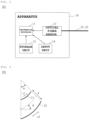
- Fig. 1 illustrates an example of a system configuration according to the present embodiment.
- an apparatus 10 is mounted on a ship 100, and the apparatus 10 is connected to a linear structure 20.
- the apparatus 10 according to the present embodiment is an apparatus that calculates behavior of the linear structure of the present disclosure, and estimates behavior of the linear structure 20, which is present in water, using parameter estimation based on data assimilation which is grounded on a distribution-type optical fiber sensor and Bayesian inference.
- Behavior of the linear structure 20 is, for example, three-dimensional coordinates of the linear structure 20.
- the three-dimensional coordinates of the linear structure 20 can be calculated using the displacement in the rotation direction of the linear structure 20 with respect to the position of at least one point of the linear structure 20 from which the position information can be acquired. Therefore, in the present embodiment, an example in which the behavior of the linear structure 20 is displacement in the rotation direction for each length L of the linear structure 20 is described.
- Fig. 2 illustrates an example of a hardware configuration of the apparatus 10.
- the apparatus 10 of the present embodiment includes an information processor 11, a storage unit 12, an optical fiber sensor 13, and an input unit 14.
- the input unit 14 is any means that enables parameters to be inputted, such as a keyboard or a touch panel.
- the optical fiber sensor 13 is connected to optical fibers 21 and 22 that are arranged along the linear structure 20.
- the optical fiber sensor 13 detects values of strain ⁇ 1 and ⁇ 2 in the two optical fibers 21 and 22.
- An optical fiber sensor using a BOTDR (Brillouin Optical Time Domain Reflectometer) is an example of means for detecting values of strain in the optical fibers 21 and 22, for example. In the following description, a case where the optical fiber sensor 13 is a BOTDR is assumed.
- the information processor 11 calculates behavior of the linear structure 20 by using the strain detected by the optical fiber sensor 13.
- the displacement of the linear structure 20 in the rotation direction can be obtained using the length L of the linear structure 20 and a deflection angle ⁇ [rad] with respect to the length L of the linear structure 20. Therefore, the information processor 11 calculates the deflection angle ⁇ [rad] with respect to each length L of the linear structure 20 by using the values of the strain ⁇ 1 and ⁇ 2 of the linear structure 20.
- the information processor 11 calculates the deflection angle ⁇ [rad] with respect to each length L of the linear structure 20 as the behavior of the linear structure 20 is described.
- the information processor 11 forecasts behavior of the linear structure 20 by using a simulator.
- the information processor 11 uses freely selected parameters to simulate the behavior of the linear structure 20 and calculates the state quantity U(t).
- the information processor 11 uses a state quantity U(t) to calculate displacement in the rotation direction with respect to each length L of the linear structure 20.
- the storage unit 12 stores any data used for the processing by the information processor 11 and stores the processing result of the information processor 11.
- the data used for the processing by the information processor 11 includes a simulation program for forcasting the behavior of the linear structure 20 and parameters used by the simulation program.
- the apparatus 10 according to the present embodiment can also be realized by a computer and a program, and the program can be recorded on a recording medium or provided over a network. Details will be described hereinbelow.
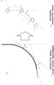
- the two optical fibers 21 and 22 are placed along the linear structure 20 in water, and as illustrated in Fig. 3 , the cores of the optical fibers 21 and 22 are deformed in accordance with the shape of the linear structure 20, and the values of the strain ⁇ 1 and ⁇ 2 are observed by the optical fiber sensor 13.
- the deflection angle ⁇ in Formula (1) corresponds to the displacement in the rotation direction, which is obtained as a simulation forecasted value.
- deflection angles ⁇ 1 and ⁇ 2 using actual measurement correspond to deflection angles ⁇ 1 and ⁇ 2 using simulation forecasted values.
- H is an observation matrix for extracting the displacement of the linear structure 20 in the rotation direction from the state quantity U(t) obtained by simulation.
- w(t) is an observation error.
- the observation error w(t) can be handled by assuming that same follows any probability distribution.
- the observation matrix H is a matrix (N+1) ⁇ 9(N+1).
- the observation data is the deflection angle data y
- a simulation forecasted value u extracted from the state quantity U is the displacement in the rotation direction, but changes can be made as appropriate, according to the combination of the observation data and the simulation forecasted values.
- a merging particle filter is used, and a plurality of particles are replicated according to the likelihood together with observation data, and the ensemble, which is a set of particles, is updated by taking the weighted sum.
- the absolute likelihood of each particle is the infinite product of the observation data likelihood for each element, and for the relative likelihood of each element, a normal distribution, defined by the average value of the displacement in the rotation direction and the standard deviation of the observation error, is assumed and derived as a probability density function of the normal distribution.
- Formulae (4) and (5) are used to calculate the absolute likelihood and the relative likelihood, respectively.
- ⁇ i t ⁇ i t ⁇ i ⁇ i t
- ⁇ (i) (t) and ⁇ (i) (t) represent the absolute likelihood and the relative likelihood of the i-th particle, respectively;
- P n (i) (t) represents the likelihood of the n-th element in the i-th particle,
- t- ⁇ t) represents the displacement in the rotation direction of the n-th element in the i-th particle;
- y n (t) represents the deflection angle of the observation data of the corresponding portion;
- W n (t) represents the observation error of the corresponding portion.
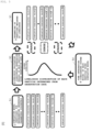
- Fig. 5 illustrates an example of a processing flow of the information processor 11.
- the processing flow of the information processor 11 includes steps S1 to S4.
- the information processor 11 executes step S1, and upon acquiring the observation data, executes steps S2 to S4.
- steps S2 to S4 the information processor 11 executes behavior estimation using the sequential data assimilation method.
- Step S1 The uncertain parameters in the simulation model are represented by a plurality of discrete values, and the behavior of the linear structure 20 is forecasted using each of the discrete values. As a result, a plurality of simulation forecasted values are generated.
- a simulation forecasted value is referred to as a particle.
- Step S2 Upon acquiring the observation data, the likelihood of each particle is calculated using the acquired observation data. At this time, an observation error may be considered as indicated in Formula (4).
- Step S3 At least one of the plurality of discrete values is updated on the basis of the likelihood, and resampling of particles weighted by likelihood is performed.
- Step S4 Time integration of each particle is performed using the simulation model. At this time, system noise may be considered.
- Step S1 In considering dynamic simulation of the linear structure 20, an assumed range of an uncertain parameter (for example, the deflection angle ⁇ ) is represented by discrete values ( ⁇ 1 , ⁇ 2 , whil, ⁇ N ), and a simulation forecasted value is obtained for each case (referred to as a particle).
- the discrete values within the assumed range are inputted from the input unit 14, for example.
- the simulation is performed, for example, by applying each parameter ( ⁇ 1 , ⁇ 2 , whil, ⁇ N ) to a model in which a linear structure, made of elastic rubber (Young's modulus: 5.0 ⁇ 10 5 Pa) having a length of 40 m, a diameter of 0.5 m, and a density of 1000 kg/m3, is hung straight in still water, and the upper end of the linear structure is subjected to single vibration in the horizontal direction with an amplitude of 2 m and a period of about 1.5 s for 10 seconds.
- the state quantity U(t) when each parameter is used is obtained, and the displacement in the horizontal direction with respect to each length L is determined.
- steps S2 to S4 are sequentially repeated.
- Step S2 The information processor 11 compares the obtained observation data with an assumed observation error and each simulation forecasted value, and thus obtains the likelihood of each particle. For example, the absolute likelihood and the relative likelihood for each length L are obtained using Formulae (3) and (4).
- Step S3 Particle resampling is performed using the relative likelihood obtained in step S2 as a weight. For example, when the relative likelihoods of the particles k', k'+1, and k'+2 are high and the relative likelihoods of the other particles are low, the discrete values in the parameter ranges used by the particles k', k'+1, and k'+2 are increased, the discrete values in parameter ranges other than those of the particles k', k'+1, and k'+2 are decreased, and the discrete values ( ⁇ 1 , ⁇ 2 , ......, ⁇ N ) of new parameters are generated. Further, a simulation forecasted value is obtained using each parameter. As a result, a particle using a parameter having a high relative likelihood is calculated.
- Step S4 Time integration using dynamic simulation is performed on the resampled particles. As a result, the simulation forecasted value at the time of acquiring the next observation data is obtained for each element length L.
- the dynamic simulation is performed using, for example, the model used in step S1. The process then returns to step S2.
- steps S2 to S4 are repeated a predetermined number of times, a weighted average of the plurality of particles is taken for each length L of the element.
- the number of repeats of steps S2 to S4 may be a certain number, but the setup may be such that a weighted average of a plurality of particles is taken on the occasion of the relative likelihood being below a certain value.
- any number having a high relative likelihood can be adopted.
- the information processor 11 is capable of performing highly accurate behavior estimation. Furthermore, in the present embodiment, because the strain of the entire vertically long linear structure 20, having a large amount of information, is measured, and the likelihood, taking into account the entire linear structure 20, is calculated using Formula (4), it is possible to attain the advantageous effect of enabling an enhanced forecast accuracy for the linear structure 20.
- the uncertain parameter may be any parameter used in a simulator that forecasts the behavior of the linear structure 20 in water.
- the parameters used in the simulator for estimating behavior of the linear structure 20 in water include the tension T of the linear structure 20, the velocity of the ship 100, the elasticity E of the linear structure 20, the cross-sectional area A of the linear structure 20, the velocity V with respect to the fluid around the linear structure 20, the mass m per unit length of the linear structure 20, the fluid density ⁇ w around the linear structure 20, the resistance coefficient C t in the tangential direction of the linear structure 20, the resistance coefficient Cn in the normal direction with respect to the linear structure 20, the additional mass coefficient Cmf in the fluid acceleration motion, the additional mass coefficient Cmb in the element acceleration motion, the diameter d of the linear structure 20, and the like.
- a particle is generated for each combination of uncertain parameters in step S1, and discrete values of a parameter range are densified for a combination of parameters having a high likelihood in step S3. Accordingly, the present disclosure affords the advantageous effect of enabling an enhanced forecast accuracy for the linear structure 20 by using a combination of high likelihood parameters, even in a case where there are two or more uncertain parameters.
- the present embodiment relates to a simulation result of behavior estimation to which the sequential data assimilation method described in the first embodiment is applied.
- the time division was 0.001 second
- the length L per element was 1 m
- the fluid density was 997 kg/m3
- the coefficients of the tangential resistance coefficient Ct, the normal resistance coefficient Cn, and the additional mass coefficient Cmb were 1.5, 0.03, and 1, respectively.
- the observation data was the deflection angle ⁇ with respect to each length of 1 m obtained from the strain distribution of the linear structure, and the sampling rate was 25 Hz.
- ⁇ 1 is a weight of a particle having the highest relative likelihood
- ⁇ 2 is a weight of a particle having the second highest relative likelihood
- ⁇ 3 is a weight of a particle having the third highest relative likelihood.
- the start of the sequential data assimilation was after 2 seconds from the start of the simulation, and the unknown parameters to be estimated were mode attenuation ratios. It is assumed that the attenuation ratios of the primary mode and the secondary mode are equal.
- Fig. 6 illustrates that the simulation was performed, with the sequential data assimilation unperformed and the mode attenuation ratio retaining the uncertainty of the prior distribution, and a shape estimation result of the linear structure was obtained ten seconds after.
- the vertical axis represents the distance in the depth direction
- the horizontal axis represents the distance in the horizontal direction.
- the coordinates (0, 0) indicate the position of the linear structure 20 fixed to the ship 100 illustrated in Fig. 1 .
- a particularly large uncertain element (estimation error) exists in the region of maximum amplitude in the horizontal direction.
- Fig. 7 illustrates a temporal change in an estimation error where sequential data assimilation was applied. It can be seen that together with the application of sequential data assimilation (after two seconds), the estimation error is significantly reduced and converges to an approximately true value after 8 seconds of application.
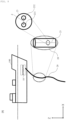
- a state where the cores of the two optical fibers 21 and 22 have the interval d therebetween was described as an example, instead of the optical fibers 21 and 22, one multicore optical fiber 23 in which a plurality of cores 231 and 232 are arranged to have the interval d in the cladding of the optical fiber, as illustrated in Fig. 8 , may be used.
- Fig. 8 illustrates, as an example, the multicore optical fiber 23 which has two cores, the number of cores may be two or more, and the arrangement of the cores may take any form. For example, a four-core fiber having one core at the center and three cores on the outer periphery thereof may be used.
- observation data is sequentially fetched using a distribution-type sensor, highly accurate real-time behavior estimation can be performed. Furthermore, according to the present disclosure, when estimating behavior of a vertically long linear structure having a large amount of information, by measuring the entire strain, the accuracy of the behavior estimation can be enhanced in comparison with a case where the position coordinates of one intermediate point are measured using single point measurement.
- the present disclosure can be applied to the information communication industry.
Landscapes
- Physics & Mathematics (AREA)
- General Physics & Mathematics (AREA)
- Engineering & Computer Science (AREA)
- Aviation & Aerospace Engineering (AREA)
- Electromagnetism (AREA)
- Length Measuring Devices By Optical Means (AREA)
- Optical Transform (AREA)
Abstract
Description
- The present disclosure relates to an apparatus and methods for estimating the behavior of a linear structure in water, such as a submarine cable, by means of reflectometry technology using an optical fiber.
- A method for detecting the behavior of a linear structure in water, such as a submarine cable, by using an optical fiber sensor has been proposed. An optical fiber sensor is technology for measuring and analyzing a reflection spectrum of an optical fiber by using OFDR (Optical Frequency Domain Reflectometry) to derive a three-dimensional shape of a measured target. Fiber optic sensors are capable of dynamic measurements over long distances. However, in the monitoring of a linear structure in water, there is the problem of an accumulation of errors due to integral calculations along the optical fiber.
- In addition, as a method suitable for estimating a phenomenon in real time, there exists the example of behavior estimation using sequential data assimilation in which data assimilation is performed for each obtainment of time observation data (see, for example,
Non Patent Literature 1.). However, this method employs, as observation data, discrete position information of a linear structure acquired by a global positioning system (GPS) or the like. In order to acquire the position information, it is necessary to receive radio waves in water. Therefore, as the depth in water increases, acquiring the position information becomes problematic and obtaining continuous data in the length direction becomes difficult. - Non Patent Literature 1: J. V. Grindheim, I. Revahug, and E. Pedersen, "Utilizing the ensemble kalman filter and ensemble kalman smoother for combined state and parameter estimation of a three dimensional towed underwater cable model", Journal of Offshore Mechanics and Arctic Engineering, Vol. 139, No. 6, p. 061303, 2017.
- An object of the present disclosure is to enable the behavior of a linear structure in water to be estimated.
- An apparatus and a method according to the present disclosure include:
- expressing at least one parameter in a plurality of discrete values, and forecasting behavior of a linear structure by using each of the discrete values;
- acquiring behavior of the linear structure detected using an optical fiber;
- calculating a likelihood between the forecasted behavior of the linear structure and the acquired behavior of the linear structure;
- updating at least one of the plurality of discrete values on the basis of the likelihood; and
- calculating behavior of the linear structure by using the updated plurality of discrete values.
- The present disclosure enables the behavior of a linear structure in water to be estimated.
-
-
Fig. 1 illustrates an example of a system configuration of the present disclosure. -
Fig. 2 illustrates an example of a hardware configuration of the apparatus of the present disclosure. -
Fig. 3 illustrates an example of a modified image of two cores. -
Fig. 4 illustrates an example of displacement in a rotation direction. -
Fig. 5 illustrates an example of a flow describing the method of the present disclosure. -
Fig. 6 illustrates a behavior estimation result of a linear structure in a case where the present disclosure is not used. -
Fig. 7 illustrates a behavior estimation result of a linear structure in a case where the present disclosure is used. -
Fig. 8 illustrates an example of a system configuration of the present disclosure. - Hereinafter, embodiments of the present disclosure will be described in detail with reference to the drawings. Note that the present disclosure is not limited to the following embodiments. These examples are merely examples, and the present disclosure can be carried out in a variety of forms obtained through modifications and improvements based on the knowledge of those skilled in the art. Note that components having the same reference signs in the present specification and the drawings indicate the same components.
-
Fig. 1 illustrates an example of a system configuration according to the present embodiment. In the system according to the present embodiment, anapparatus 10 is mounted on aship 100, and theapparatus 10 is connected to alinear structure 20. Theapparatus 10 according to the present embodiment is an apparatus that calculates behavior of the linear structure of the present disclosure, and estimates behavior of thelinear structure 20, which is present in water, using parameter estimation based on data assimilation which is grounded on a distribution-type optical fiber sensor and Bayesian inference. - Behavior of the
linear structure 20 is, for example, three-dimensional coordinates of thelinear structure 20. The three-dimensional coordinates of thelinear structure 20 can be calculated using the displacement in the rotation direction of thelinear structure 20 with respect to the position of at least one point of thelinear structure 20 from which the position information can be acquired. Therefore, in the present embodiment, an example in which the behavior of thelinear structure 20 is displacement in the rotation direction for each length L of thelinear structure 20 is described. -
Fig. 2 illustrates an example of a hardware configuration of theapparatus 10. Theapparatus 10 of the present embodiment includes aninformation processor 11, astorage unit 12, anoptical fiber sensor 13, and aninput unit 14. Theinput unit 14 is any means that enables parameters to be inputted, such as a keyboard or a touch panel. Theoptical fiber sensor 13 is connected tooptical fibers linear structure 20. - The
optical fiber sensor 13 detects values of strain ε1 and ε2 in the twooptical fibers optical fibers optical fiber sensor 13 is a BOTDR is assumed. - The
information processor 11 calculates behavior of thelinear structure 20 by using the strain detected by theoptical fiber sensor 13. The displacement of thelinear structure 20 in the rotation direction can be obtained using the length L of thelinear structure 20 and a deflection angle θ[rad] with respect to the length L of thelinear structure 20. Therefore, theinformation processor 11 calculates the deflection angle θ[rad] with respect to each length L of thelinear structure 20 by using the values of the strain ε1 and ε2 of thelinear structure 20. Hereinafter, an example in which theinformation processor 11 calculates the deflection angle θ[rad] with respect to each length L of thelinear structure 20 as the behavior of thelinear structure 20 is described. - Furthermore, the
information processor 11 forecasts behavior of thelinear structure 20 by using a simulator. For example, theinformation processor 11 uses freely selected parameters to simulate the behavior of thelinear structure 20 and calculates the state quantity U(t). Theinformation processor 11 uses a state quantity U(t) to calculate displacement in the rotation direction with respect to each length L of thelinear structure 20. - In addition to the values of the strain ε1 and ε2 detected by the
optical fiber sensor 13, thestorage unit 12 stores any data used for the processing by theinformation processor 11 and stores the processing result of theinformation processor 11. The data used for the processing by theinformation processor 11 includes a simulation program for forcasting the behavior of thelinear structure 20 and parameters used by the simulation program. Theapparatus 10 according to the present embodiment can also be realized by a computer and a program, and the program can be recorded on a recording medium or provided over a network. Details will be described hereinbelow. - The two
optical fibers linear structure 20 in water, and as illustrated inFig. 3 , the cores of theoptical fibers linear structure 20, and the values of the strain ε1 and ε2 are observed by theoptical fiber sensor 13. The deflection angle θ[rad], obtained by integrating the curvature of thelinear structure 20 in water over a length L[m], is represented by Formula (1) including the distance d[m] between the cores of theoptical fibers
[Formula 1]
- When the length L is the unit length for forecasting the behavior of the
linear structure 20, the deflection angle θ in Formula (1) corresponds to the displacement in the rotation direction, which is obtained as a simulation forecasted value. For example, as illustrated inFig. 4 , deflection angles θ1 and θ2 using actual measurement correspond to deflection angles θ1 and θ2 using simulation forecasted values. - Given that the observation data of a strain distribution detected by the
optical fiber sensor 13 is converted into deflection angle data y(t) for each length L, Formula (2) is derived.
[Formula 2]
- Here, H is an observation matrix for extracting the displacement of the
linear structure 20 in the rotation direction from the state quantity U(t) obtained by simulation. w(t) is an observation error. The observation error w(t) can be handled by assuming that same follows any probability distribution. - The observation matrix H is represented by the following formula.
[Formula 3]
- When the deflection angle θ of the
linear structure 20 is calculated, the observation matrix H is a matrix (N+1) × 9(N+1). In the present embodiment, an example is illustrated in which the observation data is the deflection angle data y, and a simulation forecasted value u extracted from the state quantity U is the displacement in the rotation direction, but changes can be made as appropriate, according to the combination of the observation data and the simulation forecasted values. - In the sequential data assimilation method, a merging particle filter is used, and a plurality of particles are replicated according to the likelihood together with observation data, and the ensemble, which is a set of particles, is updated by taking the weighted sum. The absolute likelihood of each particle is the infinite product of the observation data likelihood for each element, and for the relative likelihood of each element, a normal distribution, defined by the average value of the displacement in the rotation direction and the standard deviation of the observation error, is assumed and derived as a probability density function of the normal distribution.
- Formulae (4) and (5) are used to calculate the absolute likelihood and the relative likelihood, respectively.
[Formula 4]

- Here, λ(i)(t) and γ(i)(t) represent the absolute likelihood and the relative likelihood of the i-th particle, respectively; Pn (i)(t) represents the likelihood of the n-th element in the i-th particle, un (i)(t|t-Δt) represents the displacement in the rotation direction of the n-th element in the i-th particle; yn(t) represents the deflection angle of the observation data of the corresponding portion; and Wn(t) represents the observation error of the corresponding portion.
-
Fig. 5 illustrates an example of a processing flow of theinformation processor 11. The processing flow of theinformation processor 11 includes steps S1 to S4. Theinformation processor 11 executes step S1, and upon acquiring the observation data, executes steps S2 to S4. In steps S2 to S4, theinformation processor 11 executes behavior estimation using the sequential data assimilation method. - Step S1: The uncertain parameters in the simulation model are represented by a plurality of discrete values, and the behavior of the
linear structure 20 is forecasted using each of the discrete values. As a result, a plurality of simulation forecasted values are generated. In the present disclosure, a simulation forecasted value is referred to as a particle. - Step S2: Upon acquiring the observation data, the likelihood of each particle is calculated using the acquired observation data. At this time, an observation error may be considered as indicated in Formula (4).
- Step S3: At least one of the plurality of discrete values is updated on the basis of the likelihood, and resampling of particles weighted by likelihood is performed.
- Step S4: Time integration of each particle is performed using the simulation model. At this time, system noise may be considered.
- Hereinafter, each step will be described in detail.
- Step S1: In considering dynamic simulation of the
linear structure 20, an assumed range of an uncertain parameter (for example, the deflection angle θ) is represented by discrete values (θ1, θ2, ......, θN), and a simulation forecasted value is obtained for each case (referred to as a particle). The discrete values within the assumed range are inputted from theinput unit 14, for example. The simulation is performed, for example, by applying each parameter (θ1, θ2, ......, θN) to a model in which a linear structure, made of elastic rubber (Young's modulus: 5.0 × 10⁵ Pa) having a length of 40 m, a diameter of 0.5 m, and a density of 1000 kg/m3, is hung straight in still water, and the upper end of the linear structure is subjected to single vibration in the horizontal direction with an amplitude of 2 m and a period of about 1.5 s for 10 seconds. As a result, the state quantity U(t) when each parameter is used is obtained, and the displacement in the horizontal direction with respect to each length L is determined. - Once the
optical fiber sensor 13 detects the values of the strain ε1 and ε2 and theinformation processor 11 calculates the deflection angle θ to obtain the observation data for each length L, steps S2 to S4 are sequentially repeated. - Step S2: The
information processor 11 compares the obtained observation data with an assumed observation error and each simulation forecasted value, and thus obtains the likelihood of each particle. For example, the absolute likelihood and the relative likelihood for each length L are obtained using Formulae (3) and (4). - Step S3: Particle resampling is performed using the relative likelihood obtained in step S2 as a weight. For example, when the relative likelihoods of the particles k',
k'+ 1, andk'+ 2 are high and the relative likelihoods of the other particles are low, the discrete values in the parameter ranges used by the particles k',k'+ 1, andk'+ 2 are increased, the discrete values in parameter ranges other than those of the particles k',k'+ 1, andk'+ 2 are decreased, and the discrete values (θ1, θ2, ......, θN) of new parameters are generated. Further, a simulation forecasted value is obtained using each parameter. As a result, a particle using a parameter having a high relative likelihood is calculated. - Step S4: Time integration using dynamic simulation is performed on the resampled particles. As a result, the simulation forecasted value at the time of acquiring the next observation data is obtained for each element length L. The dynamic simulation is performed using, for example, the model used in step S1. The process then returns to step S2.
- After steps S2 to S4 are repeated a predetermined number of times, a weighted average of the plurality of particles is taken for each length L of the element. Here, the number of repeats of steps S2 to S4 may be a certain number, but the setup may be such that a weighted average of a plurality of particles is taken on the occasion of the relative likelihood being below a certain value. In addition, as the number of particles whose the weighted average is taken, any number having a high relative likelihood can be adopted.
- As described hereinabove, in the present embodiment, because the observation data by the
optical fiber sensor 13 is sequentially fetched in step S2, theinformation processor 11 is capable of performing highly accurate behavior estimation. Furthermore, in the present embodiment, because the strain of the entire vertically longlinear structure 20, having a large amount of information, is measured, and the likelihood, taking into account the entirelinear structure 20, is calculated using Formula (4), it is possible to attain the advantageous effect of enabling an enhanced forecast accuracy for thelinear structure 20. - In the present embodiment, an example in which the uncertain parameter is the deflection angle θ is illustrated, but the uncertain parameter may be any parameter used in a simulator that forecasts the behavior of the
linear structure 20 in water. For example, the parameters used in the simulator for estimating behavior of thelinear structure 20 in water include the tension T of thelinear structure 20, the velocity of theship 100, the elasticity E of thelinear structure 20, the cross-sectional area A of thelinear structure 20, the velocity V with respect to the fluid around thelinear structure 20, the mass m per unit length of thelinear structure 20, the fluid density ρw around thelinear structure 20, the resistance coefficient Ct in the tangential direction of thelinear structure 20, the resistance coefficient Cn in the normal direction with respect to thelinear structure 20, the additional mass coefficient Cmf in the fluid acceleration motion, the additional mass coefficient Cmb in the element acceleration motion, the diameter d of thelinear structure 20, and the like. - Note that, in a case where there are two or more uncertain parameters, a particle is generated for each combination of uncertain parameters in step S1, and discrete values of a parameter range are densified for a combination of parameters having a high likelihood in step S3. Accordingly, the present disclosure affords the advantageous effect of enabling an enhanced forecast accuracy for the
linear structure 20 by using a combination of high likelihood parameters, even in a case where there are two or more uncertain parameters. - The present embodiment relates to a simulation result of behavior estimation to which the sequential data assimilation method described in the first embodiment is applied.
- The advantageous effect of the behavior estimation was verified using a model in which a
linear structure 20 made of elastic rubber (Young's modulus: 5.0 × 10⁵ Pa), having a length of 40 m, a diameter of 0.5 m, and a density of 1000 kg/m3, is hung straight in still water, and the upper end of the linear structure was subjected to single vibration in the horizontal direction with an amplitude of 2 m and a period of about 1.5 s for 10 seconds. - For the simulation, the time division was 0.001 second, the length L per element was 1 m, the fluid density was 997 kg/m3, and the coefficients of the tangential resistance coefficient Ct, the normal resistance coefficient Cn, and the additional mass coefficient Cmb were 1.5, 0.03, and 1, respectively. The observation data was the deflection angle θ with respect to each length of 1 m obtained from the strain distribution of the linear structure, and the sampling rate was 25 Hz.
- The number of weighted averages taken in the merging particle filter was 3, and the weighting factor was set as [Formula 6]

- Here, α1 is a weight of a particle having the highest relative likelihood, α2 is a weight of a particle having the second highest relative likelihood, and α3 is a weight of a particle having the third highest relative likelihood.
- The start of the sequential data assimilation was after 2 seconds from the start of the simulation, and the unknown parameters to be estimated were mode attenuation ratios. It is assumed that the attenuation ratios of the primary mode and the secondary mode are equal.
-
Fig. 6 illustrates that the simulation was performed, with the sequential data assimilation unperformed and the mode attenuation ratio retaining the uncertainty of the prior distribution, and a shape estimation result of the linear structure was obtained ten seconds after. The vertical axis represents the distance in the depth direction, and the horizontal axis represents the distance in the horizontal direction. The coordinates (0, 0) indicate the position of thelinear structure 20 fixed to theship 100 illustrated inFig. 1 . In light ofFig 6 , it can be seen that a particularly large uncertain element (estimation error) exists in the region of maximum amplitude in the horizontal direction. -
Fig. 7 illustrates a temporal change in an estimation error where sequential data assimilation was applied. It can be seen that together with the application of sequential data assimilation (after two seconds), the estimation error is significantly reduced and converges to an approximately true value after 8 seconds of application. - Note that although, in the above-described embodiment, a state where the cores of the two
optical fibers optical fibers optical fiber 23 in which a plurality ofcores Fig. 8 , may be used. Moreover, althoughFig. 8 illustrates, as an example, the multicoreoptical fiber 23 which has two cores, the number of cores may be two or more, and the arrangement of the cores may take any form. For example, a four-core fiber having one core at the center and three cores on the outer periphery thereof may be used. - Because, according to the present disclosure, observation data is sequentially fetched using a distribution-type sensor, highly accurate real-time behavior estimation can be performed. Furthermore, according to the present disclosure, when estimating behavior of a vertically long linear structure having a large amount of information, by measuring the entire strain, the accuracy of the behavior estimation can be enhanced in comparison with a case where the position coordinates of one intermediate point are measured using single point measurement.
- The present disclosure can be applied to the information communication industry.
-
- 10 Apparatus
- 11 Information processor
- 12 Storage unit
- 13 Optical fiber sensor
- 14 Input unit
- 20 Linear structure
- 21, 22 Optical fiber
- 23 Multicore optical fiber
- 231, 232 Core
- 100 Ship
Claims (7)
- An apparatus that:expresses at least one parameter in a plurality of discrete values, and forecasts behavior of a linear structure by using each of the discrete values;acquires behavior of the linear structure detected using an optical fiber;calculates a likelihood between the forecasted behavior of the linear structure and the acquired behavior of the linear structure;updates at least one of the plurality of discrete values on the basis of the likelihood; andcalculates behavior of the linear structure by using the updated plurality of discrete values.
- The apparatus according to claim 1, comprising:an optical fiber sensor in which an optical fiber is arranged along the linear structure and that detects strain of the optical fiber,wherein the behavior of the linear structure is acquired by calculating a deflection angle with respect to each unit length of the linear structure, on the basis of the strain detected by the optical fiber sensor.
- The apparatus according to claim 2,wherein the optical fiber sensor detects the strain of a plurality of optical fibers arranged along the linear structure, andcalculates the deflection angle with respect to each unit length of the linear structure, on the basis of a difference in the strain per unit length of the plurality of optical fibers.
- The apparatus according to claim 2,wherein the optical fiber sensor detects the strain of a plurality of cores included in a multi-core optical fiber arranged along the linear structure, andcalculates the deflection angle with respect to each unit length of the linear structure, on the basis of a difference in the strain per unit length of the plurality of cores.
- The apparatus according to any of claims 2 to 4,wherein the forecasted behavior of the linear structure is displacement in a rotation direction with respect to each unit length of the linear structure, andwherein the likelihood is calculated, on the basis of the forecasted displacement in the rotation direction with respect to each unit length of the linear structure and the calculated deflection angle with respect to each unit length of the linear structure.
- The apparatus according to any of claims 1 to 5,wherein behaviors of the linear structure are forecasted by using the updated plurality of discrete values,wherein weighting according to the likelihood is applied to the forecasted behaviors of the linear structure, andwherein the behavior of the linear structure is calculated by taking an average of the weighted behaviors of the linear structure.
- A method, comprising:expressing at least one parameter in a plurality of discrete values, and forecasting behavior of a linear structure by using each of the discrete values;acquiring behavior of the linear structure detected using an optical fiber;calculating a likelihood between the forecasted behavior of the linear structure and the acquired behavior of the linear structure;updating at least one of the plurality of discrete values on the basis of the likelihood; andcalculating behavior of the linear structure by using the updated plurality of discrete values.
Applications Claiming Priority (2)
| Application Number | Priority Date | Filing Date | Title |
|---|---|---|---|
| JP2020185198 | 2020-11-05 | ||
| PCT/JP2021/038481 WO2022097466A1 (en) | 2020-11-05 | 2021-10-18 | Device and method for calculating behavior of linear structure |
Publications (4)
| Publication Number | Publication Date |
|---|---|
| EP4242582A1 true EP4242582A1 (en) | 2023-09-13 |
| EP4242582A4 EP4242582A4 (en) | 2024-09-25 |
| EP4242582B1 EP4242582B1 (en) | 2025-09-24 |
| EP4242582B8 EP4242582B8 (en) | 2025-11-05 |
Family
ID=81457195
Family Applications (1)
| Application Number | Title | Priority Date | Filing Date |
|---|---|---|---|
| EP21889019.2A Active EP4242582B8 (en) | 2020-11-05 | 2021-10-18 | Device and method for calculating behavior of linear structure |
Country Status (4)
| Country | Link |
|---|---|
| US (1) | US12467805B2 (en) |
| EP (1) | EP4242582B8 (en) |
| JP (1) | JP7627912B2 (en) |
| WO (1) | WO2022097466A1 (en) |
Families Citing this family (1)
| Publication number | Priority date | Publication date | Assignee | Title |
|---|---|---|---|---|
| US20250060213A1 (en) * | 2021-12-24 | 2025-02-20 | Nippon Telegraph And Telephone Corporation | Shape measurement system and shape measurement method |
Family Cites Families (6)
| Publication number | Priority date | Publication date | Assignee | Title |
|---|---|---|---|---|
| JP2006145388A (en) * | 2004-11-19 | 2006-06-08 | Shimizu Corp | Device and method for measuring bending of boring hole |
| US8773650B2 (en) * | 2009-09-18 | 2014-07-08 | Intuitive Surgical Operations, Inc. | Optical position and/or shape sensing |
| WO2012037319A2 (en) * | 2010-09-17 | 2012-03-22 | Luna Innovations Incorporated | Compensating for non-ideal multi-core optical fiber structure |
| US8972310B2 (en) * | 2012-03-12 | 2015-03-03 | The Boeing Company | Method for identifying structural deformation |
| CN110435812A (en) * | 2012-05-30 | 2019-11-12 | 赛创尼克株式会社 | Control method for monitoring by real-time measurement of marine structures |
| US11067387B2 (en) * | 2014-02-28 | 2021-07-20 | Koninklijke Philips N.V. | Adaptive instrument kinematic model optimization for optical shape sensed instruments |
-
2021
- 2021-10-18 US US18/034,899 patent/US12467805B2/en active Active
- 2021-10-18 EP EP21889019.2A patent/EP4242582B8/en active Active
- 2021-10-18 WO PCT/JP2021/038481 patent/WO2022097466A1/en not_active Ceased
- 2021-10-18 JP JP2022560701A patent/JP7627912B2/en active Active
Also Published As
| Publication number | Publication date |
|---|---|
| US20240019323A1 (en) | 2024-01-18 |
| US12467805B2 (en) | 2025-11-11 |
| EP4242582B8 (en) | 2025-11-05 |
| JP7627912B2 (en) | 2025-02-07 |
| EP4242582B1 (en) | 2025-09-24 |
| JPWO2022097466A1 (en) | 2022-05-12 |
| EP4242582A4 (en) | 2024-09-25 |
| WO2022097466A1 (en) | 2022-05-12 |
Similar Documents
| Publication | Publication Date | Title |
|---|---|---|
| US12061083B2 (en) | System and method for wave prediction | |
| Liu et al. | Turning telecommunication fiber‐optic cables into distributed acoustic sensors for vibration‐based bridge health monitoring | |
| Bao et al. | Integrated ARMA model method for damage detection of subsea pipeline system | |
| Wolfram et al. | On the estimation of Morison force coefficients and their predictive accuracy for very rough circular cylinders | |
| EP3926320B1 (en) | Aerial optical fiber cable inspection method, aerial optical fiber cable inspection device, and program | |
| CN118393424B (en) | A high-precision underwater acoustic positioning method and system | |
| KR102728368B1 (en) | Method and system for sea state evaluation based on sensor fusion data of ship | |
| US20130282285A1 (en) | Method and device for determining the movements of a fluid from remote measurements of radial velocities | |
| CN112001559A (en) | A Deformation Monitoring and Prediction Method | |
| Chen et al. | DIC‐Based Operational Modal Analysis of Bridges | |
| JP6521777B2 (en) | Tsunami monitoring system | |
| US20260043827A1 (en) | Correction of turbulence intensity | |
| EP3708992B1 (en) | Estimating device, estimating method, and program storing medium | |
| Ma et al. | Simultaneous Estimation of Submerged Floating Tunnel Displacement and Mooring Cable Tension through FIR Filter‐Based Strain and Acceleration Fusion | |
| EP4242582B1 (en) | Device and method for calculating behavior of linear structure | |
| Iliopoulos et al. | Continuous fatigue assessment of offshore wind turbines using a stress prediction technique | |
| Katakami et al. | Immediate and high‐precision hypocentral determination for earthquake early warning applications using distributed acoustic sensing | |
| CN121112914B (en) | Pile foundation landing section submarine cable scouring length monitoring method and system based on optical fiber sensing | |
| JP5007391B2 (en) | Tsunami source estimation method, tsunami height prediction method, and related technologies | |
| KR102388378B1 (en) | Apparatus and method for analysising seismic response based on deep learning | |
| CN118393600A (en) | Method and system for estimating effective elastic thickness of rock ring | |
| Akhmerov et al. | Acoustic energy mapping method for acousto-optical non-destructive testing system with automated positioning | |
| Kojima et al. | Estimation of Subsea Line Structure Behavior Based on Sequential Data Assimilation With Distributed Sensing | |
| Kwon | Uncertainty of bridge flutter velocity measured at wind tunnel tests | |
| CN120802271B (en) | A Method and System for Measuring Extremely Shallow Waters Using a Tilt-Mounted Single-Beam Echo Sounder |
Legal Events
| Date | Code | Title | Description |
|---|---|---|---|
| STAA | Information on the status of an ep patent application or granted ep patent |
Free format text: STATUS: THE INTERNATIONAL PUBLICATION HAS BEEN MADE |
|
| PUAI | Public reference made under article 153(3) epc to a published international application that has entered the european phase |
Free format text: ORIGINAL CODE: 0009012 |
|
| STAA | Information on the status of an ep patent application or granted ep patent |
Free format text: STATUS: REQUEST FOR EXAMINATION WAS MADE |
|
| 17P | Request for examination filed |
Effective date: 20230329 |
|
| AK | Designated contracting states |
Kind code of ref document: A1 Designated state(s): AL AT BE BG CH CY CZ DE DK EE ES FI FR GB GR HR HU IE IS IT LI LT LU LV MC MK MT NL NO PL PT RO RS SE SI SK SM TR |
|
| DAV | Request for validation of the european patent (deleted) | ||
| DAX | Request for extension of the european patent (deleted) | ||
| REG | Reference to a national code |
Ref country code: DE Ref legal event code: R079 Free format text: PREVIOUS MAIN CLASS: G01B0021000000 Ipc: G01L0005105000 Ref document number: 602021039318 Country of ref document: DE |
|
| A4 | Supplementary search report drawn up and despatched |
Effective date: 20240826 |
|
| RIC1 | Information provided on ipc code assigned before grant |
Ipc: G01B 11/16 20060101ALI20240820BHEP Ipc: G01M 5/00 20060101ALI20240820BHEP Ipc: G01L 5/105 20200101AFI20240820BHEP |
|
| GRAP | Despatch of communication of intention to grant a patent |
Free format text: ORIGINAL CODE: EPIDOSNIGR1 |
|
| STAA | Information on the status of an ep patent application or granted ep patent |
Free format text: STATUS: GRANT OF PATENT IS INTENDED |
|
| INTG | Intention to grant announced |
Effective date: 20250513 |
|
| GRAS | Grant fee paid |
Free format text: ORIGINAL CODE: EPIDOSNIGR3 |
|
| GRAA | (expected) grant |
Free format text: ORIGINAL CODE: 0009210 |
|
| STAA | Information on the status of an ep patent application or granted ep patent |
Free format text: STATUS: THE PATENT HAS BEEN GRANTED |
|
| GRAT | Correction requested after decision to grant or after decision to maintain patent in amended form |
Free format text: ORIGINAL CODE: EPIDOSNCDEC |
|
| AK | Designated contracting states |
Kind code of ref document: B1 Designated state(s): AL AT BE BG CH CY CZ DE DK EE ES FI FR GB GR HR HU IE IS IT LI LT LU LV MC MK MT NL NO PL PT RO RS SE SI SK SM TR |
|
| REG | Reference to a national code |
Ref country code: GB Ref legal event code: FG4D |
|
| REG | Reference to a national code |
Ref country code: CH Ref legal event code: EP |
|
| RAP4 | Party data changed (patent owner data changed or rights of a patent transferred) |
Owner name: NTT, INC. Owner name: THE UNIVERSITY OF TOKYO |
|
| REG | Reference to a national code |
Ref country code: CH Ref legal event code: Q17 Free format text: ST27 STATUS EVENT CODE: U-0-0-Q10-Q17 (AS PROVIDED BY THE NATIONAL OFFICE) Effective date: 20251008 |
|
| REG | Reference to a national code |
Ref country code: DE Ref legal event code: R096 Ref document number: 602021039318 Country of ref document: DE |
|
| REG | Reference to a national code |
Ref country code: IE Ref legal event code: FG4D |
|
| PGFP | Annual fee paid to national office [announced via postgrant information from national office to epo] |
Ref country code: DE Payment date: 20251023 Year of fee payment: 5 |
|
| PGFP | Annual fee paid to national office [announced via postgrant information from national office to epo] |
Ref country code: GB Payment date: 20251103 Year of fee payment: 5 |
|
| PG25 | Lapsed in a contracting state [announced via postgrant information from national office to epo] |
Ref country code: NO Free format text: LAPSE BECAUSE OF FAILURE TO SUBMIT A TRANSLATION OF THE DESCRIPTION OR TO PAY THE FEE WITHIN THE PRESCRIBED TIME-LIMIT Effective date: 20251224 |
|
| REG | Reference to a national code |
Ref country code: LT Ref legal event code: MG9D |
|
| PGFP | Annual fee paid to national office [announced via postgrant information from national office to epo] |
Ref country code: AT Payment date: 20260113 Year of fee payment: 5 |
|
| PG25 | Lapsed in a contracting state [announced via postgrant information from national office to epo] |
Ref country code: FI Free format text: LAPSE BECAUSE OF FAILURE TO SUBMIT A TRANSLATION OF THE DESCRIPTION OR TO PAY THE FEE WITHIN THE PRESCRIBED TIME-LIMIT Effective date: 20250924 |
|
| PG25 | Lapsed in a contracting state [announced via postgrant information from national office to epo] |
Ref country code: HR Free format text: LAPSE BECAUSE OF FAILURE TO SUBMIT A TRANSLATION OF THE DESCRIPTION OR TO PAY THE FEE WITHIN THE PRESCRIBED TIME-LIMIT Effective date: 20250924 |
|
| PGFP | Annual fee paid to national office [announced via postgrant information from national office to epo] |
Ref country code: FR Payment date: 20251103 Year of fee payment: 5 |
|
| PG25 | Lapsed in a contracting state [announced via postgrant information from national office to epo] |
Ref country code: GR Free format text: LAPSE BECAUSE OF FAILURE TO SUBMIT A TRANSLATION OF THE DESCRIPTION OR TO PAY THE FEE WITHIN THE PRESCRIBED TIME-LIMIT Effective date: 20251225 |
|
| PG25 | Lapsed in a contracting state [announced via postgrant information from national office to epo] |
Ref country code: SE Free format text: LAPSE BECAUSE OF FAILURE TO SUBMIT A TRANSLATION OF THE DESCRIPTION OR TO PAY THE FEE WITHIN THE PRESCRIBED TIME-LIMIT Effective date: 20250924 |
|
| PG25 | Lapsed in a contracting state [announced via postgrant information from national office to epo] |
Ref country code: LV Free format text: LAPSE BECAUSE OF FAILURE TO SUBMIT A TRANSLATION OF THE DESCRIPTION OR TO PAY THE FEE WITHIN THE PRESCRIBED TIME-LIMIT Effective date: 20250924 |
|
| PG25 | Lapsed in a contracting state [announced via postgrant information from national office to epo] |
Ref country code: BG Free format text: LAPSE BECAUSE OF FAILURE TO SUBMIT A TRANSLATION OF THE DESCRIPTION OR TO PAY THE FEE WITHIN THE PRESCRIBED TIME-LIMIT Effective date: 20250924 |
|
| PG25 | Lapsed in a contracting state [announced via postgrant information from national office to epo] |
Ref country code: RS Free format text: LAPSE BECAUSE OF FAILURE TO SUBMIT A TRANSLATION OF THE DESCRIPTION OR TO PAY THE FEE WITHIN THE PRESCRIBED TIME-LIMIT Effective date: 20251224 |
|
| REG | Reference to a national code |
Ref country code: NL Ref legal event code: MP Effective date: 20250924 |
|
| PG25 | Lapsed in a contracting state [announced via postgrant information from national office to epo] |
Ref country code: NL Free format text: LAPSE BECAUSE OF FAILURE TO SUBMIT A TRANSLATION OF THE DESCRIPTION OR TO PAY THE FEE WITHIN THE PRESCRIBED TIME-LIMIT Effective date: 20250924 |
|
| REG | Reference to a national code |
Ref country code: AT Ref legal event code: MK05 Ref document number: 1840661 Country of ref document: AT Kind code of ref document: T Effective date: 20250924 |
|
| PG25 | Lapsed in a contracting state [announced via postgrant information from national office to epo] |
Ref country code: SM Free format text: LAPSE BECAUSE OF FAILURE TO SUBMIT A TRANSLATION OF THE DESCRIPTION OR TO PAY THE FEE WITHIN THE PRESCRIBED TIME-LIMIT Effective date: 20250924 |
|
| PG25 | Lapsed in a contracting state [announced via postgrant information from national office to epo] |
Ref country code: ES Free format text: LAPSE BECAUSE OF FAILURE TO SUBMIT A TRANSLATION OF THE DESCRIPTION OR TO PAY THE FEE WITHIN THE PRESCRIBED TIME-LIMIT Effective date: 20250924 |
|
| PG25 | Lapsed in a contracting state [announced via postgrant information from national office to epo] |
Ref country code: AT Free format text: LAPSE BECAUSE OF FAILURE TO SUBMIT A TRANSLATION OF THE DESCRIPTION OR TO PAY THE FEE WITHIN THE PRESCRIBED TIME-LIMIT Effective date: 20250924 |
|
| PG25 | Lapsed in a contracting state [announced via postgrant information from national office to epo] |
Ref country code: IT Free format text: LAPSE BECAUSE OF FAILURE TO SUBMIT A TRANSLATION OF THE DESCRIPTION OR TO PAY THE FEE WITHIN THE PRESCRIBED TIME-LIMIT Effective date: 20250924 Ref country code: RO Free format text: LAPSE BECAUSE OF FAILURE TO SUBMIT A TRANSLATION OF THE DESCRIPTION OR TO PAY THE FEE WITHIN THE PRESCRIBED TIME-LIMIT Effective date: 20250924 |
|
| PG25 | Lapsed in a contracting state [announced via postgrant information from national office to epo] |
Ref country code: IS Free format text: LAPSE BECAUSE OF FAILURE TO SUBMIT A TRANSLATION OF THE DESCRIPTION OR TO PAY THE FEE WITHIN THE PRESCRIBED TIME-LIMIT Effective date: 20260124 |
|
| PG25 | Lapsed in a contracting state [announced via postgrant information from national office to epo] |
Ref country code: CZ Free format text: LAPSE BECAUSE OF FAILURE TO SUBMIT A TRANSLATION OF THE DESCRIPTION OR TO PAY THE FEE WITHIN THE PRESCRIBED TIME-LIMIT Effective date: 20250924 Ref country code: PT Free format text: LAPSE BECAUSE OF FAILURE TO SUBMIT A TRANSLATION OF THE DESCRIPTION OR TO PAY THE FEE WITHIN THE PRESCRIBED TIME-LIMIT Effective date: 20260126 |
|
| PG25 | Lapsed in a contracting state [announced via postgrant information from national office to epo] |
Ref country code: PL Free format text: LAPSE BECAUSE OF FAILURE TO SUBMIT A TRANSLATION OF THE DESCRIPTION OR TO PAY THE FEE WITHIN THE PRESCRIBED TIME-LIMIT Effective date: 20250924 |
|
| PG25 | Lapsed in a contracting state [announced via postgrant information from national office to epo] |
Ref country code: SK Free format text: LAPSE BECAUSE OF FAILURE TO SUBMIT A TRANSLATION OF THE DESCRIPTION OR TO PAY THE FEE WITHIN THE PRESCRIBED TIME-LIMIT Effective date: 20250924 |
|
| REG | Reference to a national code |
Ref country code: CH Ref legal event code: H13 Free format text: ST27 STATUS EVENT CODE: U-0-0-H10-H13 (AS PROVIDED BY THE NATIONAL OFFICE) Effective date: 20260527 |
|
| PG25 | Lapsed in a contracting state [announced via postgrant information from national office to epo] |
Ref country code: LU Free format text: LAPSE BECAUSE OF NON-PAYMENT OF DUE FEES Effective date: 20251018 |
|
| REG | Reference to a national code |
Ref country code: BE Ref legal event code: MM Effective date: 20251031 |
|
| REG | Reference to a national code |
Ref country code: DE Ref legal event code: R097 Ref document number: 602021039318 Country of ref document: DE |
|
| PG25 | Lapsed in a contracting state [announced via postgrant information from national office to epo] |
Ref country code: LT Free format text: LAPSE BECAUSE OF FAILURE TO SUBMIT A TRANSLATION OF THE DESCRIPTION OR TO PAY THE FEE WITHIN THE PRESCRIBED TIME-LIMIT Effective date: 20250924 Ref country code: MC Free format text: LAPSE BECAUSE OF FAILURE TO SUBMIT A TRANSLATION OF THE DESCRIPTION OR TO PAY THE FEE WITHIN THE PRESCRIBED TIME-LIMIT Effective date: 20250924 |
|
| PG25 | Lapsed in a contracting state [announced via postgrant information from national office to epo] |
Ref country code: DK Free format text: LAPSE BECAUSE OF FAILURE TO SUBMIT A TRANSLATION OF THE DESCRIPTION OR TO PAY THE FEE WITHIN THE PRESCRIBED TIME-LIMIT Effective date: 20250924 |
|
| PG25 | Lapsed in a contracting state [announced via postgrant information from national office to epo] |
Ref country code: CH Free format text: LAPSE BECAUSE OF NON-PAYMENT OF DUE FEES Effective date: 20251031 Ref country code: BE Free format text: LAPSE BECAUSE OF NON-PAYMENT OF DUE FEES Effective date: 20251031 |
|
| PLBE | No opposition filed within time limit |
Free format text: ORIGINAL CODE: 0009261 |
|
| STAA | Information on the status of an ep patent application or granted ep patent |
Free format text: STATUS: NO OPPOSITION FILED WITHIN TIME LIMIT |
|
| REG | Reference to a national code |
Ref country code: CH Ref legal event code: L10 Free format text: ST27 STATUS EVENT CODE: U-0-0-L10-L00 (AS PROVIDED BY THE NATIONAL OFFICE) Effective date: 20260805 |