EP4242554A1 - Regenerator of temperature, heat pump including such a regenerator and method of implementing thereof - Google Patents
Regenerator of temperature, heat pump including such a regenerator and method of implementing thereof Download PDFInfo
- Publication number
- EP4242554A1 EP4242554A1 EP22160602.3A EP22160602A EP4242554A1 EP 4242554 A1 EP4242554 A1 EP 4242554A1 EP 22160602 A EP22160602 A EP 22160602A EP 4242554 A1 EP4242554 A1 EP 4242554A1
- Authority
- EP
- European Patent Office
- Prior art keywords
- elastomeric material
- regenerator
- box
- temperature
- tubes
- Prior art date
- Legal status (The legal status is an assumption and is not a legal conclusion. Google has not performed a legal analysis and makes no representation as to the accuracy of the status listed.)
- Pending
Links
Images


Classifications
-
- F—MECHANICAL ENGINEERING; LIGHTING; HEATING; WEAPONS; BLASTING
- F25—REFRIGERATION OR COOLING; COMBINED HEATING AND REFRIGERATION SYSTEMS; HEAT PUMP SYSTEMS; MANUFACTURE OR STORAGE OF ICE; LIQUEFACTION SOLIDIFICATION OF GASES
- F25B—REFRIGERATION MACHINES, PLANTS OR SYSTEMS; COMBINED HEATING AND REFRIGERATION SYSTEMS; HEAT PUMP SYSTEMS
- F25B23/00—Machines, plants or systems, with a single mode of operation not covered by groups F25B1/00 - F25B21/00, e.g. using selective radiation effect
-
- F—MECHANICAL ENGINEERING; LIGHTING; HEATING; WEAPONS; BLASTING
- F25—REFRIGERATION OR COOLING; COMBINED HEATING AND REFRIGERATION SYSTEMS; HEAT PUMP SYSTEMS; MANUFACTURE OR STORAGE OF ICE; LIQUEFACTION SOLIDIFICATION OF GASES
- F25B—REFRIGERATION MACHINES, PLANTS OR SYSTEMS; COMBINED HEATING AND REFRIGERATION SYSTEMS; HEAT PUMP SYSTEMS
- F25B21/00—Machines, plants or systems, using electric or magnetic effects
Definitions
- the present invention concerns the field of heat pumps and more particularly relates to a regenerator of temperature and a method of implementing thereof.
- caloric materials see their entropy vary on either an electromagnetic field or mechanical stress/pressure.
- the development of more performant materials is accompanied by the need for adequate heat engine design, as well experimental proof of concepts.
- Several breakthrough from a system point of view were achieved using especially magnetocaloric and elastocaloric metallic compounds, or electrocaloric ceramics. This went in parallel to the discovery of materials exhibiting especially high magneto/electro or elastocaloric activity, such as magnetocaloric Heusler alloys, ferroelectric multilayer ceramics or barocaloric elastomeric materials.
- Caloric materials exhibit time variations of temperature when driven cyclically.
- a system is required to convert it into a spatial gradient, i.e. to move heat from a cold spot to a hot spot.
- One solution consists of physically moving the caloric material in contact with heat source or heat sink (single stage systems).
- regenerative systems attracted a lot of attention since it both solves the time to space conversion issue, but also permits a temperature span of the system higher than the adiabatic temperature change of the material. It consists of moving a heat transfer fluid in contact with the active material with a cyclic motion for transporting heat from the cold reservoir to the active material, and from the active material to the hot reservoir.
- the necessary very large deformation >500%) remains an issue to implement either single-stage or regenerative systems.
- the objective is achieved by a specific design of an efficient regenerator of temperature based on a plurality of elastomeric material tubes, cyclically stretched along their axis, with a heat transfer fluid flowing inside the tubes.
- This design also solves the problem of the grip of the plurality of elastomeric material tubes, that should withstand the axial stress induced by the tubes stretching (>MPa).
- the invention is directed to a regenerator of temperature comprising a plurality of N elastomeric material tubes, at least one actuator, a first and a second box, each having a bottom with a plurality N of holes therein, their respective bottoms facing each other, each hole of the first box being in fluid communication with a hole of the second box by means of one elastomeric material tube, each end of the elastomeric material tube being sealingly anchored in its respective hole, at least one of the first or second boxes being translatable by at least one actuator so that the plurality of elastomeric material tubes undergoes successively stretching and release conditions, means for sucking into said box and then discharging from said box the fluid flowing through the elastomeric material tubes.
- At least one of the first or second boxes may have plunger means therein for sucking into said box and then discharging from said box the fluid flowing through the elastomeric material tubes
- the first box is disposed above the second box, the first and second boxes being aligned along a substantially vertical axis, only the second box having piston means.
- the cooling power is proportional to the number of tubes N that can be increased to reach targeted cooling power.
- the outer diameter of the elastomeric material tubes may range from 2 mm to 5 mm at a non-stretched state.
- the internal diameter of the elastomeric material tubes may range from 1 mm to 3 mm at a non-stretched state.
- the elastomeric material may be weakly cross-linked elastomer, including natural or artificial rubber.
- Elastomeric materials are defined for the purpose of the present invention as polymers with viscoelasticity (i.e., both viscosity and elasticity) and with weak intermolecular forces, generally low Young's modulus and high failure strain compared with other materials. Such materials have rubber-like properties.
- Each of the monomers which link to form the polymer is usually a compound of several elements among carbon, hydrogen, oxygen and silicon.
- Elastomers are amorphous polymers maintained above their glass transition temperature, so that considerable molecular reconformation, without breaking of covalent bonds, is feasible. At ambient temperatures, such rubbers are thus relatively compliant (E ⁇ 3 MPa) and deformable.
- Thermoplastic elastomers are materials that combine many of the attributes and features of both vulcanized thermoset rubber and thermoplastic materials. Hence, they present an elastomeric behavior while being processed as a thermoplastic polymer. Most thermoplastic elastomers are co-polymers having rigid and flexible moieties in their back-bone. The synthesis of these elastomers, either by chain-growth or step-growth polymerization, results in a wide spectra of thermoplastic elastomers.
- Rubber-like solids with elastic properties are called elastomers. Polymer chains are held together in these materials by relatively weak intermolecular bonds, which permit the polymers to stretch in response to macroscopic stresses.
- Elastomers are usually thermosets (requiring vulcanization) but may also be thermoplastic (see thermoplastic elastomer).
- the long polymer chains cross-link during curing, i.e., vulcanizing.
- the molecular structure of elastomers can be imagined as a 'spaghetti and meatball' structure, with the meatballs signifying cross-links.
- the elasticity is derived from the ability of the long chains to reconfigure themselves to distribute an applied stress.
- the covalent cross-linkages ensure that the elastomer will return to its original configuration when the stress is removed. As a result of this extreme flexibility, elastomers can reversibly extend from 5-700%, depending on the specific material. Without the cross-linkages or with short, uneasily reconfigured chains, the applied stress would result in a permanent deformation.
- the length of the elastomeric material tubes may range from 20 mm to 50 mm at a non-stretched state.
- each bottom of the first and second boxes is constituted of a plate, for example of acrylonitrile butadiene styrene, each end of the elastomeric material tubes being sealingly anchored in his respective hole, each hole being preferably of conical shape, by means of a hollow cone preferably made of polymer.
- each bottom may be coated with a layer of sealing material preferably of epoxy resin and preferably according a thickness around 10 mm.
- the first and the second boxes may be each enclosed in an adiabatic chamber.
- the first and/or the second boxes comprises a first and a second outputs intended to connect the inside of said box with a fluid loop.
- the invention is otherwise directed to a heat pump comprising a first and a second heat exchangers, a first and a second pumps, a first and a second fluid loops passing respectively through said heat exchangers and said pumps and being each provided with a first and a second fluid junctions, wherein said heat pump includes a regenerator of temperature according to the invention, the first and the second boxes each comprising a first and a second outputs, said regenerator of temperature being in fluid communication with fluid loops by means of said first and a second outputs connected respectively with said first and second fluid junctions.
- the fluid loops may be used for controlling the temperature of the first and second boxes to the temperature of the heat source and heat sink respectively.
- the heat sink may be ambient temperature room, whereas the heat source may be a closed volume being therefore refrigerated by the system.
- the fluid circulating in the loop is a liquid selected from the list defined by water, oils, mixture of water and glycol, charged water.
- the invention is otherwise directed to a method of implementing a regenerator of temperature according to the invention, and in order to cool down a fluid at the cold end, contained in the second box of the regenerator, and to warm up a fluid at the hot end, contained in the first box of the regenerator, characterized in that:
- the release conditions of the plurality of elastomeric material tubes correspond to an extension ranging from 300% to 400% of the initial length, while the stretched conditions of the plurality of elastomeric material tubes correspond to strain ranging from 500% to 600% of the initial length.
- alternative embodiments of the invention can be particularly considered that comprise only a selection of the described features, isolated from the other described features (even if this selection is isolated within a sentence comprising these other features), if this selection of features is sufficient to provide a technical advantage or to differentiate the invention from the prior art.
- This selection comprises at least one feature, preferably functional without structural details, or with only part of the structural details if this part only is sufficient to provide a technical advantage or to differentiate the invention from the prior art.
- the regenerator of temperature comprises a plurality of N elastomeric material tubes 1, two actuators 23, 33, a first 2 and a second 3 boxes, each having a bottom 20, 30 with a plurality N of holes 201, 301 therein.
- each hole 201 of the first 2 box being in fluid communication with a hole 301 of the second 3 box by means of one elastomeric material tube 1.
- Each end of the elastomeric material tube is sealingly anchored in his respective hole 201, 301 as depicted on Fig. 2 and Fig. 3 .
- Elastomeric materials are defined for the purpose of the present invention as polymers with viscoelasticity (i.e., both viscosity and elasticity) and with weak intermolecular forces, generally low Young's modulus and high failure strain compared with other materials. Such materials have rubber-like properties.
- Each of the monomers which link to form the polymer is usually a compound of several elements among carbon, hydrogen, oxygen and silicon.
- Elastomers are amorphous polymers maintained above their glass transition temperature, so that considerable molecular reconformation, without breaking of covalent bonds, is feasible. At ambient temperatures, such rubbers are thus relatively compliant (E ⁇ 3 MPa) and deformable.
- Rubber-like solids with elastic properties are called elastomers. Polymer chains are held together in these materials by relatively weak intermolecular bonds, which permit the polymers to stretch in response to macroscopic stresses.
- Elastomers are usually thermosets (requiring vulcanization) but may also be thermoplastic (see thermoplastic elastomer).
- the long polymer chains cross-link during curing, i.e., vulcanizing.
- the molecular structure of elastomers can be imagined as a 'spaghetti and meatball' structure, with the meatballs signifying cross-links.
- the elasticity is derived from the ability of the long chains to reconfigure themselves to distribute an applied stress.
- the covalent cross-linkages ensure that the elastomer will return to its original configuration when the stress is removed. As a result of this extreme flexibility, elastomers can reversibly extend from 5-700%, depending on the specific material. Without the cross-linkages or with short, uneasily reconfigured chains, the applied stress would result in a permanent deformation.
- Thermoplastic elastomers are materials that combine many of the attributes and features of both vulcanized thermoset rubber and thermoplastic materials. Hence, they present an elastomeric behavior while being processed as a thermoplastic polymer. Most thermoplastic elastomers are co-polymers having rigid and flexible moieties in their back-bone. The synthesis of these elastomers, either by chain-growth or step-growth polymerization, results in a wide spectra of thermoplastic elastomers.
- the first and second boxes are respectively translatable by the actuator 23, 33 so that the plurality of elastomeric material tubes 1 undergoes successively stretching and a release conditions under loads provided by the actuator 23.
- the first box is disposed above the second box, so that the first 2 and second 3 boxes are aligned along a substantially vertical axis and only the second box located under the first box is provided with piston means 35 and actuator 36, for sucking into said box and then discharging from said box the fluid flowing through the elastomeric material tubes.
- the fluid contained in the first box 2 can flow through the tubes into the second box 3 and flows back into the first box under the action of piston means 35 actuated by the actuator 36.
- a pump 53 could be used for sucking into second box 3 and then discharging from said box the fluid flowing through the elastomeric material tubes.
- first 2 and second 3 boxes may be aligned along a substantially horizontal axis, with first and second plunger means associated to each boxes with dedicated actuators.
- the outer diameter of the elastomeric material tubes ranges advantageously from 2 mm to 5 mm at a non-stretched state.
- the internal diameter of the elastomeric material tubes ranges advantageously from 1 mm to 3 mm at a non-stretched state.
- the length of the elastomeric material tubes ranges advantageously from 20 mm to 50 mm at a non-stretched state.
- each bottom 20, 30 of the first 2 and second 3 boxes is constituted of a plate preferably of acrylonitrile butadiene styrene.
- each end of the elastomeric material tubes is achieved by complementarity of form between the holes 201, 301 and hollow cones 202, 302 inserted into the elastomeric material tubes 1.
- Each hole 201, 301 may be preferably of conical shape to enhance the sealability.
- This assembly by complementarity of form makes it possible to fix the end of the tubes to the bottom by minimizing the constraints on the tubes and by maximizing the sealing area defined by defined the external surface of the tubes and the thickness of the holes.
- each bottom 20, 30 is coated with a layer of sealing material 203, 303 preferably of epoxy resin and preferably according a thickness around 10 mm.
- This layer 203, 303 permits to maintain the portion of the tubes coming out of the holes and permits to avoid concentrations of stresses in this area.
- This layer prevents the tubes from tearing and allows for more than 10 000 stretching cycles.
- the first and the second boxes are each enclosed in an adiabatic chamber 24, 34.
- the first 2 and the second 3 boxes comprises a first 21, 31 and a second 22, 32 outputs intended to connect the inside of said box with a fluid loop 4, 5.
- the implementation in a heat pump as described in Fig. 1 implies at least a heat exchanger 44, 54, a pump 43, 53 (as a diaphragm pump for example), a fluid loop 4, 5 passing respectively through said heat exchanger and said pump.
- Each fluid loop 4, 5 is provided with a first 41, 51 and a second 42, 52 fluid junctions, respectively in fluid communication with the first 21, 31 and a second 22, 32 outputs of the regenerator of temperature.
- the heat pump comprises a first and a second fluid loops 4, 5 passing respectively through heat exchangers 44, 54 and pumps 43, 53.
- Fluid loops 4, 5 are each provided with a first 41, 51 and a second 42, 52 fluid junctions, and are in fluid communication with the regenerator by means respectively of the first 21, 31 and second 22, 32 outputs connected respectively with the first 41, 51 and second 42, 52 fluid junctions.
- the fluid loops 4 and 5 are used for controlling the temperature of the first 2 and second 3 boxes to the temperature of the heat source and heat sink respectively.
- the heat sink may be ambient temperature room, whereas the heat source may be a closed volume being therefore refrigerated by the system.
- the heat pump is intended to work with a liquid selected from the list defined by water, oils, mixture of water and glycol, charged water.
- the elastomeric material may be weakly cross-linked elastomer, natural or artificial rubber.
- the method comprises the following steps as shown in Fig. 4 :
- the release conditions of the plurality of elastomeric material tubes 1 correspond to an extension ranging from 300% to 400% of the initial length, while the stretched conditions of the plurality of elastomeric material tubes 1 correspond to strain ranging from 500% to 600% of the initial length.
- a length of 1.5 m of rubber tube was first stretched up to an elongation of 6 (i.e., 9 m) and maintained stretched for several minutes. After the release of the stretching, the tube was cut into regular small length tubes of 50 mm. Each tube was mounted into the printed ABS plate 20, 30 with holes 201, 301. The ends of the tubes were then anchored onto each plate as described above by inserting elastomeric material conical tubes 202, 302, so that the rubber tubes are pressed between ABS plate 20, 30 and the conical tube 202, 302. The tubes were stretched to an elongation of 4. Epoxy resin 203, 303 was poured onto the ABS plate 20, 30 on both ends to fix the outer position of the rubber tubes 1.
- the tubes were stretched until an elongation of 6, and a second layer of epoxy was poured onto both ends, so that the total thickness of the epoxy resin reaches ⁇ 1cm.
- the tube diameter from the boundary of the epoxy was already at its final diameter, ensuring the homogeneity of the elastocaloric effect along the length of the tube.
- the fixing plates at both ends were then attached to the boxes 2, 3.
- the device was first tested without heat transfer fluid.
- the surface temperature of the rubber tubes was measured with an infrared camera (Optris Xi400, Berlin, Germany). Under cyclic elongation between 4 and 6, the adiabatic temperature change was measured ⁇ 3.8 K.
- the inner diameter of the tubes when stretched was determined by the change in the regenerator fluid volume during stretching and assuming that the volume of the rubber body is independent of the stretching.
- the stretching of the 55 rubber tubes 1 was done thanks to the linear actuator 23 (MISUMI RSDG306, Tokyo, Japan), and the motion of the fluid was given by the actuator 36 (MISUMI RSD112, Tokyo, Japan) pushing a piston pump acting as the plunger means 35.
- the box 3 was kept at a fixed position, only the box 2 was translated. Therefore, the actuator 33 was not used.
- Two laser displacement sensors (Panasonic displacement sensors HG-C1400 and HG-C1100-P, Kadoma, Japan) were added to measure the displacement of the two actuators 23, 36.
- the boxes 2, 3 were added at the ends of the regenerator. Their volume was 6.4 mL each.
- the fluid loop 5 was not added to the experimental setup intended to the characterization of the heat pump prototype only.
- conical shape diffusors (not represented in the figures) were added.
- the upper box 2 was kept open, to ensure that the pressure remains constant, and that the gravity can move back the fluid down when the plunger means 35 moves down thanks to the actuator 36.
- the fluid was chosen to be pure water.
- the fluid inside the upper box 2 was circulated through a fluid loop 4, to keep the upper box 2 inner temperature as close to room temperature as possible.
- a force sensor (Vishay Tedea Huntleigh load cell #615, Malvern, PA, USA) was mounted. It was used for measuring the mechanical work of the actuator 23 stretching the rubber tubes 1.
- the temperature was measured at several locations using two thermocouples: inside the upper box 2 and inside the lower box 3.
- Fig. 1 served as basis for an experimental setup, along with typical waveforms used for the refrigeration device characterization in Fig. 5 .
- the characterization of the refrigeration prototype included measurement of the temperature span, which was directly obtained by the thermocouples measurements.
- the heating power of the resistance placed in the insulated lower box 3 was measured.
- a voltage was applied to the heating resistance as a constant value during the characterization.
- Fig. 5 (a) shows a schematic view of the energy balance with heat and energy flowing into and out of the regenerator and where ⁇ M is the average mechanical power of the actuator stretching the tubes, Q ⁇ H is the heat power dissipated by the hot heat exchanger, Q ⁇ L heat power transferred from the ambient room to the cold tubes due to heat loss around the rubber tubes, Q ⁇ C heat power generated by the heating resistance in the bottom box.
- the device was tested at a frequency of 0.1Hz, with a displacement of the fluid inside the tubes of 240 mm on the one hand (waveforms given in Fig 5(b) ), and a displacement of the fluid inside the tubes of 80 mm on the other hand (waveforms given in Fig 5(c) ).
- a maximum temperature span of 4.7 K was obtained, i.e. the temperature of the lower box 3 decreased 4.7 K below room temperature. Heating powers of 0.6 W, 1.1 W and 1.7 W were then tested; leading to a decrease of the temperature span down to 1.3 K.
- Fig. 5 (d) shows the time signals of the temperature of the upper and lower boxes 2, 3, along with the heating power in the lower box 3 indicated as text.
- a maximum temperature span of 8.2 K was obtained, i.e. the temperature of the lower box 3 decreased 8.2 K below room temperature. Heating powers of 0.6 W and 1.0 W were then tested; leading to a cancellation of the temperature span.
- Fig. 5 (e) shows the time signals of the temperature of the upper and lower boxes 2, 3, along with the heating power in the lower box 3 indicated as text.
- Fig. 5 (f) shows the heat pump characteristic, i.e. cooling power vs. temperature span for both displacements of the fluid inside the tubes
- Fig. 5 (g) shows the Coefficient of Performance vs. temperature span for both settings of the displacement of the fluid inside the tubes.
- the cooling power per unit of mass of natural rubber tubes reaches up to 220 W.kg -1 and the temperature span of the system up to 8.2 K.
- the selection of the displacement of the fluid may be modified to adjust the targeted power and temperature span.
- regenerator geometries may be developed to further enhance the cooling power (by increasing the number of tubes) or the temperature span (by modifying the elastomeric material tubes diameters and length).
- the regenerator according to the invention permits a caloric cooling as an alternative to conventional vapor compression systems, in so far as the Total Equivalent Warming Impact (TEWI) index may be reduced by 50%-80% compared to vapor compression systems ( Aprea, International Journal of Heat and Technology, 2018 ).
- TEWI Total Equivalent Warming Impact
- the regenerator according to the invention permits moreover to enhance the compactness of the device and presents a high COP (>3).
- elastocaloric polymer such as rubber are renewable, low cost and present a low CO 2 footprint of elastomeric material fabrication (10 to 100 less than that of titanium alloys).
Landscapes
- Engineering & Computer Science (AREA)
- Physics & Mathematics (AREA)
- Mechanical Engineering (AREA)
- Thermal Sciences (AREA)
- General Engineering & Computer Science (AREA)
- Reciprocating Pumps (AREA)
- Heat-Exchange Devices With Radiators And Conduit Assemblies (AREA)
Abstract
Description
- The present invention concerns the field of heat pumps and more particularly relates to a regenerator of temperature and a method of implementing thereof.
- In the framework of potential refrigeration alternatives, caloric materials see their entropy vary on either an electromagnetic field or mechanical stress/pressure. The development of more performant materials is accompanied by the need for adequate heat engine design, as well experimental proof of concepts. Several breakthrough from a system point of view were achieved using especially magnetocaloric and elastocaloric metallic compounds, or electrocaloric ceramics. This went in parallel to the discovery of materials exhibiting especially high magneto/electro or elastocaloric activity, such as magnetocaloric Heusler alloys, ferroelectric multilayer ceramics or barocaloric elastomeric materials.
- One of the driving force of this research is the potential low Global Warming Potential of caloric-materials based devices and refrigeration solutions. This could even potentially challenge the current tradeoff between performance, toxicity and environmental issue of refrigerant gases. Among all the caloric materials, elastomeric materials as an active material could even be more effective thanks to their low CO2 footprint for their fabrication compared to metallic compounds. In addition, the availability of the materials is a key factor, for a large scale refrigeration alternative. It should be preferred materials based on abundant elements, or even coming from renewable resources (i.e. some of the elastomeric materials).
- Regarding elastomeric materials, a few achievements were presented, like the inflation of membranes and the use of torsional deformation to induce especially large elastocaloric activity. Although much promising, the upscaling possibility of these devices remains an open issue, for example when considering not only the volume of ther active material, but also its displacement during actuation. Uniaxially stretched soft elastomeric materials was proved to exhibit significant elastocaloric activity (ΔT>10°C), but the large required deformation makes it impractical for caloric cooling. Working from a pre-elongated state may lead to lower but still large activity (ΔT~3-4°C) and with an excellent fatigue life (stable until >100k cycles) as good as NiTi materials in compression. It should be noted also that different recycling routes exits for reuse of elastomeric materials in blends, or it can be used as filler materials for other applications.
- Caloric materials exhibit time variations of temperature when driven cyclically. A system is required to convert it into a spatial gradient, i.e. to move heat from a cold spot to a hot spot. One solution consists of physically moving the caloric material in contact with heat source or heat sink (single stage systems). Alternatively, regenerative systems attracted a lot of attention since it both solves the time to space conversion issue, but also permits a temperature span of the system higher than the adiabatic temperature change of the material. It consists of moving a heat transfer fluid in contact with the active material with a cyclic motion for transporting heat from the cold reservoir to the active material, and from the active material to the hot reservoir. For elastomeric materials, the necessary very large deformation (>500%) remains an issue to implement either single-stage or regenerative systems.
- Therefore, it appeared necessary to solve the limiting issue of the large strain of elastomeric materials.
- The objective is achieved by a specific design of an efficient regenerator of temperature based on a plurality of elastomeric material tubes, cyclically stretched along their axis, with a heat transfer fluid flowing inside the tubes. This design also solves the problem of the grip of the plurality of elastomeric material tubes, that should withstand the axial stress induced by the tubes stretching (>MPa).
- More precisely, the invention is directed to a regenerator of temperature comprising a plurality of N elastomeric material tubes, at least one actuator, a first and a second box, each having a bottom with a plurality N of holes therein, their respective bottoms facing each other, each hole of the first box being in fluid communication with a hole of the second box by means of one elastomeric material tube, each end of the elastomeric material tube being sealingly anchored in its respective hole, at least one of the first or second boxes being translatable by at least one actuator so that the plurality of elastomeric material tubes undergoes successively stretching and release conditions, means for sucking into said box and then discharging from said box the fluid flowing through the elastomeric material tubes.
- Optional, additional or alternative features of the invention are set forth hereafter.
- According to a preferred embodiment, at least one of the first or second boxes may have plunger means therein for sucking into said box and then discharging from said box the fluid flowing through the elastomeric material tubes
- According to a preferred embodiment, the first box is disposed above the second box, the first and second boxes being aligned along a substantially vertical axis, only the second box having piston means.
- Advantageously, the plurality of elastomeric material tubes may comprise more than N = 15 elastomeric material tubes, thereby involving N holes for each box bottom. The cooling power is proportional to the number of tubes N that can be increased to reach targeted cooling power.
- Preferably, the outer diameter of the elastomeric material tubes may range from 2 mm to 5 mm at a non-stretched state.
- Preferably, the internal diameter of the elastomeric material tubes may range from 1 mm to 3 mm at a non-stretched state.
- Preferably, the elastomeric material may be weakly cross-linked elastomer, including natural or artificial rubber.
- Elastomeric materials are defined for the purpose of the present invention as polymers with viscoelasticity (i.e., both viscosity and elasticity) and with weak intermolecular forces, generally low Young's modulus and high failure strain compared with other materials. Such materials have rubber-like properties.
- Each of the monomers which link to form the polymer is usually a compound of several elements among carbon, hydrogen, oxygen and silicon. Elastomers are amorphous polymers maintained above their glass transition temperature, so that considerable molecular reconformation, without breaking of covalent bonds, is feasible. At ambient temperatures, such rubbers are thus relatively compliant (E ≈ 3 MPa) and deformable.
- Thermoplastic elastomers are materials that combine many of the attributes and features of both vulcanized thermoset rubber and thermoplastic materials. Hence, they present an elastomeric behavior while being processed as a thermoplastic polymer. Most thermoplastic elastomers are co-polymers having rigid and flexible moieties in their back-bone. The synthesis of these elastomers, either by chain-growth or step-growth polymerization, results in a wide spectra of thermoplastic elastomers.
- Rubber-like solids with elastic properties are called elastomers. Polymer chains are held together in these materials by relatively weak intermolecular bonds, which permit the polymers to stretch in response to macroscopic stresses.
- Elastomers are usually thermosets (requiring vulcanization) but may also be thermoplastic (see thermoplastic elastomer). The long polymer chains cross-link during curing, i.e., vulcanizing. The molecular structure of elastomers can be imagined as a 'spaghetti and meatball' structure, with the meatballs signifying cross-links. The elasticity is derived from the ability of the long chains to reconfigure themselves to distribute an applied stress. The covalent cross-linkages ensure that the elastomer will return to its original configuration when the stress is removed. As a result of this extreme flexibility, elastomers can reversibly extend from 5-700%, depending on the specific material. Without the cross-linkages or with short, uneasily reconfigured chains, the applied stress would result in a permanent deformation.
- Advantageously, the length of the elastomeric material tubes may range from 20 mm to 50 mm at a non-stretched state.
- According to another preferred embodiment, each bottom of the first and second boxes is constituted of a plate, for example of acrylonitrile butadiene styrene, each end of the elastomeric material tubes being sealingly anchored in his respective hole, each hole being preferably of conical shape, by means of a hollow cone preferably made of polymer.
- Advantageously, the outside face of each bottom may be coated with a layer of sealing material preferably of epoxy resin and preferably according a thickness around 10 mm.
- Advantageously, the first and the second boxes may be each enclosed in an adiabatic chamber.
- According to a specific implementation, the first and/or the second boxes comprises a first and a second outputs intended to connect the inside of said box with a fluid loop.
- The invention is otherwise directed to a heat pump comprising a first and a second heat exchangers, a first and a second pumps, a first and a second fluid loops passing respectively through said heat exchangers and said pumps and being each provided with a first and a second fluid junctions, wherein said heat pump includes a regenerator of temperature according to the invention, the first and the second boxes each comprising a first and a second outputs, said regenerator of temperature being in fluid communication with fluid loops by means of said first and a second outputs connected respectively with said first and second fluid junctions.
- The fluid loops may be used for controlling the temperature of the first and second boxes to the temperature of the heat source and heat sink respectively. The heat sink may be ambient temperature room, whereas the heat source may be a closed volume being therefore refrigerated by the system.
- Optional, additional or alternative features of the invention are set forth hereafter.
- Preferably, the fluid circulating in the loop is a liquid selected from the list defined by water, oils, mixture of water and glycol, charged water.
- The invention is otherwise directed to a method of implementing a regenerator of temperature according to the invention, and in order to cool down a fluid at the cold end, contained in the second box of the regenerator, and to warm up a fluid at the hot end, contained in the first box of the regenerator, characterized in that:
- A first step is carried out during which the fluid contained in the first box is directed to the second box by flowing into the plurality of elastomeric material tubes, the plurality of elastomeric material tubes being under release conditions,
- A second step is carried out during which the plurality of elastomeric material tubes is stretched,
- A third step is carried out during which the fluid contained in the second box is directed to the first box by flowing into the plurality of elastomeric material stretched tubes,
- A fourth step is carried out during which the plurality of elastomeric material tubes is released.
- According to a preferred embodiment, the release conditions of the plurality of elastomeric material tubes correspond to an extension ranging from 300% to 400% of the initial length, while the stretched conditions of the plurality of elastomeric material tubes correspond to strain ranging from 500% to 600% of the initial length.
- Further advantages and features of the invention will become apparent from reading the detailed description of non-limiting implementations and embodiments, and with reference to the following accompanying drawings, in which:
-
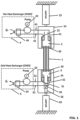
Fig. 1 is a schematic overview of a heat pump including a regenerator of temperature according to a specific embodiment of the invention; -
Fig. 2 is a perspective view of a detail of a regenerator of temperature according to a specific embodiment of the invention; -
Fig. 3 is a cross sectional view of a detail of a regenerator of temperature according to the afore mentioned specific embodiment of the invention; -
Fig. 4 is a schematic overview of the operating principle of a regenerator of temperature according to a specific embodiment of the invention; -
Fig. 5 shows (a) a schematic of the heat and energy balance, (b) waveforms for elastomeric material tubes length (stretching) and velocity of the fluid for a forward displacement of the fluid of 80mm, (c) waveforms for elastomeric material tubes length (stretching) and velocity of the fluid for a forward displacement of the fluid of 240mm (d) resulting temperatures Tupper of the upper box and Tlower of the lower box for a fluid displacement of 80mm, and for various heating power in the lower box, (e) resulting temperatures Tupper of the upper box and Tlower of the lower box for a fluid displacement of 240mm, and for various heating power in the lower box. - For the sake of clarity and conciseness, the reference signs in the figures correspond to the same elements.
- With the embodiments described hereafter being non-limiting, alternative embodiments of the invention can be particularly considered that comprise only a selection of the described features, isolated from the other described features (even if this selection is isolated within a sentence comprising these other features), if this selection of features is sufficient to provide a technical advantage or to differentiate the invention from the prior art.
- This selection comprises at least one feature, preferably functional without structural details, or with only part of the structural details if this part only is sufficient to provide a technical advantage or to differentiate the invention from the prior art.
- Furthermore, the various features, forms, alternative embodiments and embodiments of the invention can be associated with each other according to various combinations, insofar as they are not incompatible or exclusive of each other.
- According to the embodiment of
Fig. 1 , the regenerator of temperature comprises a plurality of Nelastomeric material tubes 1, twoactuators - The respective bottoms of the
first box 2 and the second 3 box facing each other, each hole 201 of the first 2 box being in fluid communication with a hole 301 of the second 3 box by means of oneelastomeric material tube 1. - Each end of the elastomeric material tube is sealingly anchored in his respective hole 201, 301 as depicted on
Fig. 2 and Fig. 3 . - Elastomeric materials are defined for the purpose of the present invention as polymers with viscoelasticity (i.e., both viscosity and elasticity) and with weak intermolecular forces, generally low Young's modulus and high failure strain compared with other materials. Such materials have rubber-like properties.
- Each of the monomers which link to form the polymer is usually a compound of several elements among carbon, hydrogen, oxygen and silicon. Elastomers are amorphous polymers maintained above their glass transition temperature, so that considerable molecular reconformation, without breaking of covalent bonds, is feasible. At ambient temperatures, such rubbers are thus relatively compliant (E ≈ 3 MPa) and deformable.
- Rubber-like solids with elastic properties are called elastomers. Polymer chains are held together in these materials by relatively weak intermolecular bonds, which permit the polymers to stretch in response to macroscopic stresses.
- Elastomers are usually thermosets (requiring vulcanization) but may also be thermoplastic (see thermoplastic elastomer). The long polymer chains cross-link during curing, i.e., vulcanizing. The molecular structure of elastomers can be imagined as a 'spaghetti and meatball' structure, with the meatballs signifying cross-links. The elasticity is derived from the ability of the long chains to reconfigure themselves to distribute an applied stress. The covalent cross-linkages ensure that the elastomer will return to its original configuration when the stress is removed. As a result of this extreme flexibility, elastomers can reversibly extend from 5-700%, depending on the specific material. Without the cross-linkages or with short, uneasily reconfigured chains, the applied stress would result in a permanent deformation.
- Thermoplastic elastomers are materials that combine many of the attributes and features of both vulcanized thermoset rubber and thermoplastic materials. Hence, they present an elastomeric behavior while being processed as a thermoplastic polymer. Most thermoplastic elastomers are co-polymers having rigid and flexible moieties in their back-bone. The synthesis of these elastomers, either by chain-growth or step-growth polymerization, results in a wide spectra of thermoplastic elastomers.
- According to the embodiment of
Fig. 1 , the first and second boxes are respectively translatable by theactuator elastomeric material tubes 1 undergoes successively stretching and a release conditions under loads provided by theactuator 23. - According to the embodiment of
Fig. 1 , the first box is disposed above the second box, so that the first 2 and second 3 boxes are aligned along a substantially vertical axis and only the second box located under the first box is provided with piston means 35 andactuator 36, for sucking into said box and then discharging from said box the fluid flowing through the elastomeric material tubes. - Due to the principle of gravity, the fluid contained in the
first box 2 can flow through the tubes into thesecond box 3 and flows back into the first box under the action of piston means 35 actuated by theactuator 36. - According to another embodiment not represented on the figures, a
pump 53 could be used for sucking intosecond box 3 and then discharging from said box the fluid flowing through the elastomeric material tubes. - According to another embodiment not represented on the figures, the first 2 and second 3 boxes may be aligned along a substantially horizontal axis, with first and second plunger means associated to each boxes with dedicated actuators.
- To obtain an efficient coefficient of performance (COP) and as established by the following test results, the
plurality 1 of elastomeric material tubes comprises preferably more than N = 15 elastomeric material tubes, thereby involving N holes 201, 301 for each bottom 20, 30. - Likewise, the outer diameter of the elastomeric material tubes ranges advantageously from 2 mm to 5 mm at a non-stretched state.
- Likewise, the internal diameter of the elastomeric material tubes ranges advantageously from 1 mm to 3 mm at a non-stretched state.
- Likewise, the length of the elastomeric material tubes ranges advantageously from 20 mm to 50 mm at a non-stretched state.
- According to a particular embodiment depicted on
Fig. 2 and 3 , each bottom 20, 30 of the first 2 and second 3 boxes is constituted of a plate preferably of acrylonitrile butadiene styrene. - The anchoring of each end of the elastomeric material tubes is achieved by complementarity of form between the holes 201, 301 and hollow cones 202, 302 inserted into the
elastomeric material tubes 1. Each hole 201, 301 may be preferably of conical shape to enhance the sealability. - This assembly by complementarity of form makes it possible to fix the end of the tubes to the bottom by minimizing the constraints on the tubes and by maximizing the sealing area defined by defined the external surface of the tubes and the thickness of the holes.
- To improve the sealability of the boxes, the outside face of each bottom 20, 30 is coated with a layer of sealing material 203, 303 preferably of epoxy resin and preferably according a thickness around 10 mm.
- This layer 203, 303 permits to maintain the portion of the tubes coming out of the holes and permits to avoid concentrations of stresses in this area.
- This layer prevents the tubes from tearing and allows for more than 10 000 stretching cycles.
- To avoid heat transfers between the inside of the boxes and the ambient, the first and the second boxes are each enclosed in an
adiabatic chamber - In order to implement the regenerator of temperature in a heat pump, the first 2 and the second 3 boxes comprises a first 21, 31 and a second 22, 32 outputs intended to connect the inside of said box with a
fluid loop 4, 5. - The implementation in a heat pump as described in
Fig. 1 implies at least aheat exchanger pump 43, 53 (as a diaphragm pump for example), afluid loop 4, 5 passing respectively through said heat exchanger and said pump. Eachfluid loop 4, 5 is provided with a first 41, 51 and a second 42, 52 fluid junctions, respectively in fluid communication with the first 21, 31 and a second 22, 32 outputs of the regenerator of temperature. - According to the embodiment depicted on
Fig. 1 , the heat pump comprises a first and asecond fluid loops 4, 5 passing respectively throughheat exchangers -
Fluid loops 4, 5 are each provided with a first 41, 51 and a second 42, 52 fluid junctions, and are in fluid communication with the regenerator by means respectively of the first 21, 31 and second 22, 32 outputs connected respectively with the first 41, 51 and second 42, 52 fluid junctions. - The
fluid loops 4 and 5 are used for controlling the temperature of the first 2 and second 3 boxes to the temperature of the heat source and heat sink respectively. The heat sink may be ambient temperature room, whereas the heat source may be a closed volume being therefore refrigerated by the system. - The heat pump is intended to work with a liquid selected from the list defined by water, oils, mixture of water and glycol, charged water.
- The elastomeric material may be weakly cross-linked elastomer, natural or artificial rubber.
- Turning now to the method of implementing a regenerator of temperature according to the invention, and in order to move the heat from the
box 3 to thebox 2, the method comprises the following steps as shown inFig. 4 : - A first step I is carried out during which the fluid contained in the
box 2 is directed to thebox 3 by flowing into the plurality ofelastomeric material tubes 1, the plurality ofelastomeric material tubes 1 being under release conditions, - A second step II is carried out during which the plurality of
elastomeric material tubes 1 is stretched, - A third step III is carried out during which the fluid contained in the
box 3 is directed to thefirst box 2 by flowing into the plurality of elastomeric material stretchedtubes 1, - A fourth step IV is carried out during which the plurality of
elastomeric material tubes 1 is released. - In order to improve the coefficient of performance (COP), the release conditions of the plurality of
elastomeric material tubes 1 correspond to an extension ranging from 300% to 400% of the initial length, while the stretched conditions of the plurality ofelastomeric material tubes 1 correspond to strain ranging from 500% to 600% of the initial length. - The features above described have been established by several tests and experimentations developed hereinafter, and based on one regenerator of temperature according to the invention.
- For the prototype fabrication, commercial grade of natural rubber tubes were selected (Omega Engineering, Norwalk, Connecticut, USA), reference OMEGAFLEX Natural Latex TYGR-18116-100.
Table 1 : Prototype dimensions, material properties, and heat pump performances Specific gravity of natural rubber tubes 0.95 Tensile strength of natural rubber tubes 24.1 MPa Elongation at break of the tubes 750% Number of tubes 55 Total mass of rubber tubes (g) 10.9 Initial internal diameter (mm) 1.59 Initial external diameter (mm) 3.18 Fully stretched internal diameter (mm) 0.77 Fully stretched external diameter (mm) 1.46 Initial Length (mm) 30 Fully stretched length (mm) 170 ΔTadiabatic (°C) 3.8 Total fluid displacement in the tubes (mm) 80 240 Cooling power (W) 0 1.0 0 1.7 Temperature span (K) 8.2 -0.2 4.7 1.3 Mechanical losses (W) 0.34 0.27 0.36 0.30 COP 0 3.7 0 5.8 Extrapolated maximum cooling power 1.0 W 2.4 W Extrapolated maximum temperature span 8.2 K 4.7 K Extrapolated COP at no temperature span 3.6 7.8 - Initially, a length of 1.5 m of rubber tube was first stretched up to an elongation of 6 (i.e., 9 m) and maintained stretched for several minutes. After the release of the stretching, the tube was cut into regular small length tubes of 50 mm. Each tube was mounted into the printed
ABS plate ABS plate ABS plate rubber tubes 1. - The tubes were stretched until an elongation of 6, and a second layer of epoxy was poured onto both ends, so that the total thickness of the epoxy resin reaches ~1cm. The tube diameter from the boundary of the epoxy was already at its final diameter, ensuring the homogeneity of the elastocaloric effect along the length of the tube. The device consisted of N=55 natural rubber tubes. The dimensions of the regenerator and the properties of the natural rubber are given in Table 1. The fixing plates at both ends were then attached to the
boxes - The device was first tested without heat transfer fluid. For this elastocaloric effect characterization, the surface temperature of the rubber tubes was measured with an infrared camera (Optris Xi400, Berlin, Germany). Under cyclic elongation between 4 and 6, the adiabatic temperature change was measured ~3.8 K. The inner diameter of the tubes when stretched was determined by the change in the regenerator fluid volume during stretching and assuming that the volume of the rubber body is independent of the stretching.
- The stretching of the 55
rubber tubes 1 was done thanks to the linear actuator 23 (MISUMI RSDG306, Tokyo, Japan), and the motion of the fluid was given by the actuator 36 (MISUMI RSD112, Tokyo, Japan) pushing a piston pump acting as the plunger means 35. In this experiment, thebox 3 was kept at a fixed position, only thebox 2 was translated. Therefore, theactuator 33 was not used. Two laser displacement sensors (Panasonic displacement sensors HG-C1400 and HG-C1100-P, Kadoma, Japan) were added to measure the displacement of the twoactuators boxes bottom box 3 was thermally insulated and a heating resistance of R=96 mΩ was added as heat source for testing purpose only. Thefluid loop 5 was not added to the experimental setup intended to the characterization of the heat pump prototype only. Inside theboxes upper box 2 was kept open, to ensure that the pressure remains constant, and that the gravity can move back the fluid down when the plunger means 35 moves down thanks to theactuator 36. The fluid was chosen to be pure water. - The fluid inside the
upper box 2 was circulated through a fluid loop 4, to keep theupper box 2 inner temperature as close to room temperature as possible. At the bottom of the entire system a force sensor (Vishay Tedea Huntleigh load cell #615, Malvern, PA, USA) was mounted. It was used for measuring the mechanical work of theactuator 23 stretching therubber tubes 1. - For testing of the elastocaloric refrigeration device, the temperature was measured at several locations using two thermocouples: inside the
upper box 2 and inside thelower box 3. -
Fig. 1 served as basis for an experimental setup, along with typical waveforms used for the refrigeration device characterization inFig. 5 . - The characterization of the refrigeration prototype included measurement of the temperature span, which was directly obtained by the thermocouples measurements. For the cooling power, the heating power of the resistance placed in the insulated
lower box 3 was measured. A voltage was applied to the heating resistance as a constant value during the characterization. The generated power was considered equivalent to the cooling power Q̇C (in watts). Due to thermal losses in the system, the regenerator actually pumps more heat than that produced by the resistance, so that its measure is an underestimation of the true cooling power of the device. It was therefore estimated in the worst case by the measured voltage on the resistance:
- The mechanical work of the
rubber tubes 1 was determined by the average over one period of the mechanical power:
- The coefficient of performance (COP) for the refrigeration was determined by:

-
Fig. 5 (a) shows a schematic view of the energy balance with heat and energy flowing into and out of the regenerator and where Ẇ M is the average mechanical power of the actuator stretching the tubes, Q̇H is the heat power dissipated by the hot heat exchanger, Q̇L heat power transferred from the ambient room to the cold tubes due to heat loss around the rubber tubes, Q̇C heat power generated by the heating resistance in the bottom box. - The device was tested at a frequency of 0.1Hz, with a displacement of the fluid inside the tubes of 240 mm on the one hand (waveforms given in
Fig 5(b) ), and a displacement of the fluid inside the tubes of 80 mm on the other hand (waveforms given inFig 5(c) ). - For a fluid displacement of 240mm, a maximum temperature span of 4.7 K was obtained, i.e. the temperature of the
lower box 3 decreased 4.7 K below room temperature. Heating powers of 0.6 W, 1.1 W and 1.7 W were then tested; leading to a decrease of the temperature span down to 1.3 K.Fig. 5 (d) shows the time signals of the temperature of the upper andlower boxes lower box 3 indicated as text. - For a fluid displacement of 80mm, a maximum temperature span of 8.2 K was obtained, i.e. the temperature of the
lower box 3 decreased 8.2 K below room temperature. Heating powers of 0.6 W and 1.0 W were then tested; leading to a cancellation of the temperature span.Fig. 5 (e) shows the time signals of the temperature of the upper andlower boxes lower box 3 indicated as text. - Table 1 gives numerical values of the experimental measurements.
-
Fig. 5 (f) shows the heat pump characteristic, i.e. cooling power vs. temperature span for both displacements of the fluid inside the tubes, andFig. 5 (g) shows the Coefficient of Performance vs. temperature span for both settings of the displacement of the fluid inside the tubes. - The cooling power per unit of mass of natural rubber tubes reaches up to 220 W.kg-1 and the temperature span of the system up to 8.2 K. The selection of the displacement of the fluid may be modified to adjust the targeted power and temperature span.
- It is worth to notice that, based on the principles described above, other regenerator geometries may be developed to further enhance the cooling power (by increasing the number of tubes) or the temperature span (by modifying the elastomeric material tubes diameters and length).
- To sum up, the regenerator according to the invention permits a caloric cooling as an alternative to conventional vapor compression systems, in so far as the Total Equivalent Warming Impact (TEWI) index may be reduced by 50%-80% compared to vapor compression systems (Aprea, International Journal of Heat and Technology, 2018).
- The regenerator according to the invention permits moreover to enhance the compactness of the device and presents a high COP (>3).
- Among caloric cooling systems, elastocaloric polymer such as rubber are renewable, low cost and present a low CO2 footprint of elastomeric material fabrication (10 to 100 less than that of titanium alloys).
Claims (15)
- A regenerator of temperature comprising a plurality of N elastomeric material tubes (1), at least one actuator (23, 33), a first (2) and a second (3) boxes, each having a bottom (20, 30) with a plurality N of holes (201, 301) therein, their respective bottoms facing each other, each hole (201) of the first (2) box being in fluid communication with a hole (301) of the second (3) box by means of one elastomeric material tube (1), each end of the elastomeric material tube being sealingly anchored in his respective hole (201, 301), at least one of the first or second boxes being translatable by the at least one actuator (23, 33) so that the plurality of elastomeric material tubes (1) undergoes successively stretching and release conditions, means (35, 36; 53) for sucking into said box and then discharging from said box the fluid flowing through the elastomeric material tubes.
- A regenerator of temperature as claimed in claim 1, characterized in that at least one of the first or second boxes has plunger means (35) therein actuated by the actuator (36) for sucking into said box and then discharging from said box the fluid flowing through the elastomeric material tubes.
- A regenerator of temperature as claimed in any one of the preceding claims, characterized in that the plurality (1) of elastomeric material tubes comprises more than N = 15 elastomeric material tubes, thereby involving N holes (201, 301) for each bottom (20, 30).
- A regenerator of temperature as claimed in any one of the preceding claims, characterized in that the thickness of the elastomeric material tubes ranges from 2 mm to 5 mm at a non-stretched state.
- A regenerator of temperature as claimed in any one of the preceding claims, characterized in that the internal diameter of the elastomeric material tubes ranges from 1 mm to 3 mm at a non-stretched state.
- A regenerator of temperature as claimed in any one of the preceding claims, characterized in that the length of the elastomeric material tubes ranges from 20 mm to 50 mm at a non-stretched state.
- A regenerator of temperature as claimed in any one of the preceding claims, characterized in that each bottom (20, 30) of the first (2) and second (3) boxes is constituted of a plate, each end of the elastomeric material tubes being sealingly anchored in his respective hole (201, 301), each hole (201, 301) being preferably of conical shape, by means of a hollow cone (202, 302).
- A regenerator of temperature as claimed in the preceding claim, characterized in that the outside face of each bottom (20, 30) is coated with a layer of sealing material preferably of epoxy resin (203, 303) and preferably according a thickness around 10 mm.
- A regenerator of temperature as claimed in any one of the preceding claims, characterized in that the first (2) and the second (3) boxes are each enclosed in an adiabatic chamber (24, 34).
- A regenerator of temperature as claimed in any one of the preceding claims, characterized in that at least one of the first (2) and the second (3) boxes comprises a first (21, 31) and a second (22, 32) outputs intended to connect the inside of said box with a fluid loop (4, 5).
- A regenerator of temperature as claimed in any of the preceding claims, characterized in that the elastomeric material is chosen within weakly cross-linked elastomers, including natural and artificial rubber.
- A heat pump comprising at a first and a second heat exchangers (44, 54), a first and a second pumps (43, 53), a first and a second fluid loops (4, 5) passing respectively through said heat exchangers and said pumps and being each provided with a first (41, 51) and a second (42, 52) fluid junctions, characterized in that said heat pump includes a regenerator of temperature as claimed in claim 10, said regenerator of temperature being in fluid communication with the fluid loops (4, 5) by means of the first (21, 31) and the second (22, 32) outputs connected respectively with the first (41, 51) and the second (42, 52) fluid junctions.
- A heat pump as claimed in the preceding claim, characterized in that the fluid circulating in the loop is a liquid selected from the list defined by water, oils, mixture of water and glycol, charged water.
- Method of implementing a regenerator of temperature according to any one of claims 1 to 11, and in order to cool down a fluid contained in the second box (3) of the regenerator, and to warm up a fluid contained in the first box (2) of the regenerator, characterized in that:- A first step I is carried out during which the fluid contained in the first box (2) is directed to the second box (3) by flowing into the plurality of elastomeric material tubes (1), the plurality of elastomeric material tubes (1) being under release conditions,- A second step II is carried out during which the plurality of elastomeric material tubes (1) is stretched,- A third step III is carried out during which the fluid contained in the second box (3) is directed to the first box (2) by flowing into the plurality of elastomeric material stretched tubes (1),- A fourth step IV is carried out during which the plurality of elastomeric material tubes (1) is released.
- Method of implementing a regenerator of temperature according to claim 14, characterized in that the release conditions of the plurality of elastomeric material tubes (1) correspond to an extension ranging from 300% to 400% of the initial length, while the stretched conditions of the plurality of elastomeric material tubes (1) correspond to strain ranging from 500% to 600% of the initial length.
Priority Applications (5)
| Application Number | Priority Date | Filing Date | Title |
|---|---|---|---|
| EP22160602.3A EP4242554A1 (en) | 2022-03-07 | 2022-03-07 | Regenerator of temperature, heat pump including such a regenerator and method of implementing thereof |
| JP2024553383A JP2025508554A (en) | 2022-03-07 | 2023-03-03 | Heat pump including heat recovery device and heat exchanger and method of carrying out the same |
| PCT/EP2023/055434 WO2023169951A1 (en) | 2022-03-07 | 2023-03-03 | Regenerator of temperature, heat pump including such a regenerator and method of implementing thereof |
| US18/844,640 US20250180254A1 (en) | 2022-03-07 | 2023-03-03 | Regenerator of temperature, heat pump including such a regenerator and method of implementing thereof |
| CN202380026065.0A CN119032246A (en) | 2022-03-07 | 2023-03-03 | Temperature regenerator, heat pump including the same, and implementation method of the temperature regenerator |
Applications Claiming Priority (1)
| Application Number | Priority Date | Filing Date | Title |
|---|---|---|---|
| EP22160602.3A EP4242554A1 (en) | 2022-03-07 | 2022-03-07 | Regenerator of temperature, heat pump including such a regenerator and method of implementing thereof |
Publications (1)
| Publication Number | Publication Date |
|---|---|
| EP4242554A1 true EP4242554A1 (en) | 2023-09-13 |
Family
ID=80682927
Family Applications (1)
| Application Number | Title | Priority Date | Filing Date |
|---|---|---|---|
| EP22160602.3A Pending EP4242554A1 (en) | 2022-03-07 | 2022-03-07 | Regenerator of temperature, heat pump including such a regenerator and method of implementing thereof |
Country Status (5)
| Country | Link |
|---|---|
| US (1) | US20250180254A1 (en) |
| EP (1) | EP4242554A1 (en) |
| JP (1) | JP2025508554A (en) |
| CN (1) | CN119032246A (en) |
| WO (1) | WO2023169951A1 (en) |
Families Citing this family (2)
| Publication number | Priority date | Publication date | Assignee | Title |
|---|---|---|---|---|
| DE102022210435B4 (en) * | 2022-09-30 | 2025-09-11 | Volkswagen Aktiengesellschaft | Elastocaloric heat pump and motor vehicle with elastocaloric heat pump |
| CN119085163B (en) * | 2024-08-01 | 2026-05-12 | 东南大学 | Compression heat exchange integrated device of compression card refrigerating system |
Family Cites Families (2)
| Publication number | Priority date | Publication date | Assignee | Title |
|---|---|---|---|---|
| US3111167A (en) * | 1960-12-29 | 1963-11-19 | Young Radiator Co | Stamped header shell-and-tube heat exchanger |
| US11703257B2 (en) * | 2019-10-01 | 2023-07-18 | Board Of Regents, The University Of Texas System | Methods for torsional refrigeration by twisted, coiled, and supercoiled fibers and systems thereof |
-
2022
- 2022-03-07 EP EP22160602.3A patent/EP4242554A1/en active Pending
-
2023
- 2023-03-03 US US18/844,640 patent/US20250180254A1/en active Pending
- 2023-03-03 JP JP2024553383A patent/JP2025508554A/en active Pending
- 2023-03-03 WO PCT/EP2023/055434 patent/WO2023169951A1/en not_active Ceased
- 2023-03-03 CN CN202380026065.0A patent/CN119032246A/en active Pending
Non-Patent Citations (2)
| Title |
|---|
| SUXIN QIANA ET AL: "A review of elastocaloric cooling: Materials, cycles and system integrations", vol. 64, 1 January 2016 (2016-01-01), pages 1 - 19, XP008180804, ISSN: 0140-7007, Retrieved from the Internet <URL:http://ac.els-cdn.com/S0140700715003783/1-s2.0-S0140700715003783-main.pdf?_tid=d 0aabdda-4749-11e6-a8fb-00000aab0f02&acdnat=1468229484_48270f438c7ba0049e64cf1b24 9383c5> [retrieved on 20220809] * |
| XIE ZHONGJIAN ET AL: "Comparison of elastocaloric effect of natural rubber with other caloric effects on different-scale cooling application cases", APPLIED THERMAL ENGINEERING, PERGAMON, OXFORD, GB, vol. 111, 30 September 2016 (2016-09-30), pages 914 - 926, XP029845173, ISSN: 1359-4311, DOI: 10.1016/J.APPLTHERMALENG.2016.09.164 * |
Also Published As
| Publication number | Publication date |
|---|---|
| US20250180254A1 (en) | 2025-06-05 |
| JP2025508554A (en) | 2025-03-26 |
| WO2023169951A1 (en) | 2023-09-14 |
| CN119032246A (en) | 2024-11-26 |
Similar Documents
| Publication | Publication Date | Title |
|---|---|---|
| US20250180254A1 (en) | Regenerator of temperature, heat pump including such a regenerator and method of implementing thereof | |
| Ianniciello et al. | Long life elastocaloric regenerator operating under compression | |
| Sebald et al. | High-performance polymer-based regenerative elastocaloric cooler | |
| US6628040B2 (en) | Electroactive polymer thermal electric generators | |
| Yang et al. | Design, fabrication, and testing of micromachined silicone rubber membrane valves | |
| KR101707599B1 (en) | Stirling cycle transducer for converting between thermal energy and mechanical energy | |
| US8025297B2 (en) | Bellows with alternating layers of high and low compliance material for dynamic applications | |
| Shin et al. | Development of hydraulic linear actuator using thin film SMA | |
| JPH08507597A (en) | Ultra-small Stirling cycle cryocooler and engine | |
| SE509730C2 (en) | Load-bearing gas-pressurized damping or padding device and method for producing a load-taking gas-pressurized and resilient damping device | |
| JP2010503377A (en) | System and method for generating electricity using a chemical heat engine and piezoelectric material | |
| US20160084544A1 (en) | Solid-state heating or cooling systems, devices, and methods | |
| US20190242624A1 (en) | Thermoacoustic device | |
| CN116888810A (en) | Cooling structure between battery cells, battery modules and battery packs | |
| CN116002076B (en) | Semiconductor temperature control-based double-pass shape memory hinge device and application method thereof | |
| Lu et al. | A quintuple-bimorph tenfold-chamber piezoelectric pump used in water-cooling system of electronic chip | |
| US11047335B2 (en) | Membrane stirling engine | |
| JP2005274101A (en) | Thermoacoustic device | |
| Haissoune et al. | Critical parameters governing elastocaloric effect in polyisoprene rubbers for solid-state cooling | |
| CN115772323A (en) | Flexible composite material with shearing hardening characteristic and shape memory function, intelligent reinforced protective equipment and preparation method | |
| Chaiwongsa et al. | Experimental investigation on the performance of the air-based standing wave thermoacoustic refrigerator using heat pipe as heat exchangers | |
| US20100293968A1 (en) | Piezo-hydraulic compressor/pressure oscillator for cryogenic cooling and other applications | |
| Catalini | Development of cooling systems with active elastocaloric regenerators | |
| Bégot et al. | A novel model and design of a MEMS Stirling cooler for local refrigeration | |
| WO2025152734A1 (en) | Elastocaloric cooling device |
Legal Events
| Date | Code | Title | Description |
|---|---|---|---|
| PUAI | Public reference made under article 153(3) epc to a published international application that has entered the european phase |
Free format text: ORIGINAL CODE: 0009012 |
|
| STAA | Information on the status of an ep patent application or granted ep patent |
Free format text: STATUS: THE APPLICATION HAS BEEN PUBLISHED |
|
| AK | Designated contracting states |
Kind code of ref document: A1 Designated state(s): AL AT BE BG CH CY CZ DE DK EE ES FI FR GB GR HR HU IE IS IT LI LT LU LV MC MK MT NL NO PL PT RO RS SE SI SK SM TR |
|
| STAA | Information on the status of an ep patent application or granted ep patent |
Free format text: STATUS: REQUEST FOR EXAMINATION WAS MADE |
|
| 17P | Request for examination filed |
Effective date: 20240313 |
|
| RBV | Designated contracting states (corrected) |
Designated state(s): AL AT BE BG CH CY CZ DE DK EE ES FI FR GB GR HR HU IE IS IT LI LT LU LV MC MK MT NL NO PL PT RO RS SE SI SK SM TR |
|
| STAA | Information on the status of an ep patent application or granted ep patent |
Free format text: STATUS: EXAMINATION IS IN PROGRESS |
|
| 17Q | First examination report despatched |
Effective date: 20250730 |