EP4242495A1 - Driving assistance system and method - Google Patents
Driving assistance system and method Download PDFInfo
- Publication number
- EP4242495A1 EP4242495A1 EP22305270.5A EP22305270A EP4242495A1 EP 4242495 A1 EP4242495 A1 EP 4242495A1 EP 22305270 A EP22305270 A EP 22305270A EP 4242495 A1 EP4242495 A1 EP 4242495A1
- Authority
- EP
- European Patent Office
- Prior art keywords
- work vehicle
- clutch
- service brake
- slope
- driving assistance
- Prior art date
- Legal status (The legal status is an assumption and is not a legal conclusion. Google has not performed a legal analysis and makes no representation as to the accuracy of the status listed.)
- Granted
Links
Images

Classifications
-
- B—PERFORMING OPERATIONS; TRANSPORTING
- B60—VEHICLES IN GENERAL
- B60T—VEHICLE BRAKE CONTROL SYSTEMS OR PARTS THEREOF; BRAKE CONTROL SYSTEMS OR PARTS THEREOF, IN GENERAL; ARRANGEMENT OF BRAKING ELEMENTS ON VEHICLES IN GENERAL; PORTABLE DEVICES FOR PREVENTING UNWANTED MOVEMENT OF VEHICLES; VEHICLE MODIFICATIONS TO FACILITATE COOLING OF BRAKES
- B60T7/00—Brake-action initiating means
- B60T7/12—Brake-action initiating means for automatic initiation; for initiation not subject to will of driver or passenger
-
- F—MECHANICAL ENGINEERING; LIGHTING; HEATING; WEAPONS; BLASTING
- F16—ENGINEERING ELEMENTS AND UNITS; GENERAL MEASURES FOR PRODUCING AND MAINTAINING EFFECTIVE FUNCTIONING OF MACHINES OR INSTALLATIONS; THERMAL INSULATION IN GENERAL
- F16H—GEARING
- F16H63/00—Control outputs from the control unit to change-speed- or reversing-gearings for conveying rotary motion or to other devices than the final output mechanism
- F16H63/40—Control outputs from the control unit to change-speed- or reversing-gearings for conveying rotary motion or to other devices than the final output mechanism comprising signals other than signals for actuating the final output mechanisms
- F16H63/46—Signals to a clutch outside the gearbox
-
- B—PERFORMING OPERATIONS; TRANSPORTING
- B60—VEHICLES IN GENERAL
- B60W—CONJOINT CONTROL OF VEHICLE SUB-UNITS OF DIFFERENT TYPE OR DIFFERENT FUNCTION; CONTROL SYSTEMS SPECIALLY ADAPTED FOR HYBRID VEHICLES; ROAD VEHICLE DRIVE CONTROL SYSTEMS FOR PURPOSES NOT RELATED TO THE CONTROL OF A PARTICULAR SUB-UNIT
- B60W30/00—Purposes of road vehicle drive control systems not related to the control of a particular sub-unit, e.g. of systems using conjoint control of vehicle sub-units
- B60W30/18—Propelling the vehicle
- B60W30/18009—Propelling the vehicle related to particular drive situations
- B60W30/18109—Braking
- B60W30/18118—Hill holding
-
- F—MECHANICAL ENGINEERING; LIGHTING; HEATING; WEAPONS; BLASTING
- F16—ENGINEERING ELEMENTS AND UNITS; GENERAL MEASURES FOR PRODUCING AND MAINTAINING EFFECTIVE FUNCTIONING OF MACHINES OR INSTALLATIONS; THERMAL INSULATION IN GENERAL
- F16D—COUPLINGS FOR TRANSMITTING ROTATION; CLUTCHES; BRAKES
- F16D48/00—External control of clutches
- F16D48/06—Control by electric or electronic means, e.g. of fluid pressure
-
- F—MECHANICAL ENGINEERING; LIGHTING; HEATING; WEAPONS; BLASTING
- F16—ENGINEERING ELEMENTS AND UNITS; GENERAL MEASURES FOR PRODUCING AND MAINTAINING EFFECTIVE FUNCTIONING OF MACHINES OR INSTALLATIONS; THERMAL INSULATION IN GENERAL
- F16H—GEARING
- F16H63/00—Control outputs from the control unit to change-speed- or reversing-gearings for conveying rotary motion or to other devices than the final output mechanism
- F16H63/40—Control outputs from the control unit to change-speed- or reversing-gearings for conveying rotary motion or to other devices than the final output mechanism comprising signals other than signals for actuating the final output mechanisms
- F16H63/48—Signals to a parking brake or parking lock; Control of parking locks or brakes being part of the transmission
-
- B—PERFORMING OPERATIONS; TRANSPORTING
- B60—VEHICLES IN GENERAL
- B60T—VEHICLE BRAKE CONTROL SYSTEMS OR PARTS THEREOF; BRAKE CONTROL SYSTEMS OR PARTS THEREOF, IN GENERAL; ARRANGEMENT OF BRAKING ELEMENTS ON VEHICLES IN GENERAL; PORTABLE DEVICES FOR PREVENTING UNWANTED MOVEMENT OF VEHICLES; VEHICLE MODIFICATIONS TO FACILITATE COOLING OF BRAKES
- B60T2201/00—Particular use of vehicle brake systems; Special systems using also the brakes; Special software modules within the brake system controller
- B60T2201/06—Hill holder; Start aid systems on inclined road
-
- B—PERFORMING OPERATIONS; TRANSPORTING
- B60—VEHICLES IN GENERAL
- B60T—VEHICLE BRAKE CONTROL SYSTEMS OR PARTS THEREOF; BRAKE CONTROL SYSTEMS OR PARTS THEREOF, IN GENERAL; ARRANGEMENT OF BRAKING ELEMENTS ON VEHICLES IN GENERAL; PORTABLE DEVICES FOR PREVENTING UNWANTED MOVEMENT OF VEHICLES; VEHICLE MODIFICATIONS TO FACILITATE COOLING OF BRAKES
- B60T2210/00—Detection or estimation of road or environment conditions; Detection or estimation of road shapes
- B60T2210/20—Road shapes
-
- B—PERFORMING OPERATIONS; TRANSPORTING
- B60—VEHICLES IN GENERAL
- B60T—VEHICLE BRAKE CONTROL SYSTEMS OR PARTS THEREOF; BRAKE CONTROL SYSTEMS OR PARTS THEREOF, IN GENERAL; ARRANGEMENT OF BRAKING ELEMENTS ON VEHICLES IN GENERAL; PORTABLE DEVICES FOR PREVENTING UNWANTED MOVEMENT OF VEHICLES; VEHICLE MODIFICATIONS TO FACILITATE COOLING OF BRAKES
- B60T2260/00—Interaction of vehicle brake system with other systems
- B60T2260/09—Complex systems; Conjoint control of two or more vehicle active control systems
-
- B—PERFORMING OPERATIONS; TRANSPORTING
- B60—VEHICLES IN GENERAL
- B60Y—INDEXING SCHEME RELATING TO ASPECTS CROSS-CUTTING VEHICLE TECHNOLOGY
- B60Y2200/00—Type of vehicle
- B60Y2200/20—Off-Road Vehicles
- B60Y2200/22—Agricultural vehicles
- B60Y2200/221—Tractors
-
- F—MECHANICAL ENGINEERING; LIGHTING; HEATING; WEAPONS; BLASTING
- F16—ENGINEERING ELEMENTS AND UNITS; GENERAL MEASURES FOR PRODUCING AND MAINTAINING EFFECTIVE FUNCTIONING OF MACHINES OR INSTALLATIONS; THERMAL INSULATION IN GENERAL
- F16D—COUPLINGS FOR TRANSMITTING ROTATION; CLUTCHES; BRAKES
- F16D2500/00—External control of clutches by electric or electronic means
- F16D2500/10—System to be controlled
- F16D2500/104—Clutch
- F16D2500/10406—Clutch position
- F16D2500/10412—Transmission line of a vehicle
-
- F—MECHANICAL ENGINEERING; LIGHTING; HEATING; WEAPONS; BLASTING
- F16—ENGINEERING ELEMENTS AND UNITS; GENERAL MEASURES FOR PRODUCING AND MAINTAINING EFFECTIVE FUNCTIONING OF MACHINES OR INSTALLATIONS; THERMAL INSULATION IN GENERAL
- F16D—COUPLINGS FOR TRANSMITTING ROTATION; CLUTCHES; BRAKES
- F16D2500/00—External control of clutches by electric or electronic means
- F16D2500/30—Signal inputs
- F16D2500/31—Signal inputs from the vehicle
- F16D2500/3108—Vehicle speed
-
- F—MECHANICAL ENGINEERING; LIGHTING; HEATING; WEAPONS; BLASTING
- F16—ENGINEERING ELEMENTS AND UNITS; GENERAL MEASURES FOR PRODUCING AND MAINTAINING EFFECTIVE FUNCTIONING OF MACHINES OR INSTALLATIONS; THERMAL INSULATION IN GENERAL
- F16D—COUPLINGS FOR TRANSMITTING ROTATION; CLUTCHES; BRAKES
- F16D2500/00—External control of clutches by electric or electronic means
- F16D2500/30—Signal inputs
- F16D2500/312—External to the vehicle
- F16D2500/3124—Driving conditions, e.g. climbing hills, cornering, traffic
-
- F—MECHANICAL ENGINEERING; LIGHTING; HEATING; WEAPONS; BLASTING
- F16—ENGINEERING ELEMENTS AND UNITS; GENERAL MEASURES FOR PRODUCING AND MAINTAINING EFFECTIVE FUNCTIONING OF MACHINES OR INSTALLATIONS; THERMAL INSULATION IN GENERAL
- F16D—COUPLINGS FOR TRANSMITTING ROTATION; CLUTCHES; BRAKES
- F16D2500/00—External control of clutches by electric or electronic means
- F16D2500/50—Problem to be solved by the control system
- F16D2500/508—Relating driving conditions
- F16D2500/50825—Hill climbing or descending
-
- F—MECHANICAL ENGINEERING; LIGHTING; HEATING; WEAPONS; BLASTING
- F16—ENGINEERING ELEMENTS AND UNITS; GENERAL MEASURES FOR PRODUCING AND MAINTAINING EFFECTIVE FUNCTIONING OF MACHINES OR INSTALLATIONS; THERMAL INSULATION IN GENERAL
- F16H—GEARING
- F16H59/00—Control inputs to control units of change-speed- or reversing-gearings for conveying rotary motion
- F16H59/60—Inputs being a function of ambient conditions
- F16H59/66—Road conditions, e.g. slope, slippery
- F16H2059/663—Road slope
-
- F—MECHANICAL ENGINEERING; LIGHTING; HEATING; WEAPONS; BLASTING
- F16—ENGINEERING ELEMENTS AND UNITS; GENERAL MEASURES FOR PRODUCING AND MAINTAINING EFFECTIVE FUNCTIONING OF MACHINES OR INSTALLATIONS; THERMAL INSULATION IN GENERAL
- F16H—GEARING
- F16H2312/00—Driving activities
- F16H2312/04—Holding or hillholding
-
- F—MECHANICAL ENGINEERING; LIGHTING; HEATING; WEAPONS; BLASTING
- F16—ENGINEERING ELEMENTS AND UNITS; GENERAL MEASURES FOR PRODUCING AND MAINTAINING EFFECTIVE FUNCTIONING OF MACHINES OR INSTALLATIONS; THERMAL INSULATION IN GENERAL
- F16H—GEARING
- F16H2312/00—Driving activities
- F16H2312/16—Coming to a halt
-
- F—MECHANICAL ENGINEERING; LIGHTING; HEATING; WEAPONS; BLASTING
- F16—ENGINEERING ELEMENTS AND UNITS; GENERAL MEASURES FOR PRODUCING AND MAINTAINING EFFECTIVE FUNCTIONING OF MACHINES OR INSTALLATIONS; THERMAL INSULATION IN GENERAL
- F16H—GEARING
- F16H59/00—Control inputs to control units of change-speed- or reversing-gearings for conveying rotary motion
- F16H59/36—Inputs being a function of speed
- F16H59/44—Inputs being a function of speed dependent on machine speed, e.g. the vehicle speed
-
- F—MECHANICAL ENGINEERING; LIGHTING; HEATING; WEAPONS; BLASTING
- F16—ENGINEERING ELEMENTS AND UNITS; GENERAL MEASURES FOR PRODUCING AND MAINTAINING EFFECTIVE FUNCTIONING OF MACHINES OR INSTALLATIONS; THERMAL INSULATION IN GENERAL
- F16H—GEARING
- F16H59/00—Control inputs to control units of change-speed- or reversing-gearings for conveying rotary motion
- F16H59/50—Inputs being a function of the status of the machine, e.g. position of doors or safety belts
- F16H59/54—Inputs being a function of the status of the machine, e.g. position of doors or safety belts dependent on signals from the brakes, e.g. parking brakes
Definitions
- the present disclosure relates to the field of driving assistance, and more particularly to a driving assistance system for a work vehicle such as a tractor.
- Work vehicles must meet safety and productivity requirements in all the tasks to which they are assigned. For instance, when a work vehicle is stopped on a slope, it must be able to resume moving in a simple and reliable manner. This includes, among others, reducing or even preventing rollback.
- the object of the present invention is to at least substantially remedy the above-mentioned drawbacks.
- the present disclosure relates to a driving assistance system for a work vehicle comprising a service brake configured to decelerate the work vehicle upon actuation of the service brake, a parking brake and a transmission including a clutch, the driving assistance system comprising a controller configured to:
- the work vehicle may an agricultural vehicle or a construction vehicle, such as a tractor, a mower or the like (a groundcare vehicle), a telehandler, etc.
- a work vehicle comprises a service brake, which is actuable by a driver of the work vehicle and is configured, upon actuation, to decelerate the work vehicle, i.e. to decrease its speed with respect to the ground. Eventually, the work vehicle may come to a complete stop, in which case a continued actuation of the service brake would keep the vehicle stationary.
- the parking brake is configured to maintain the vehicle stopped without a continued actuation thereof.
- the parking brake may be configured to be switched between an activated position and a deactivated position, and able to be left in the activated position without further actuation thereof, as opposed to the service brake which is released as soon as actuation thereof is released.
- the parking brake may not be able to decelerate the vehicle.
- a service brake and a parking brake are each known per se in the art and both are conventionally provided on vehicles.
- the parking brake is configured to be automatically activated and deactivated, and thus may be referred to as an assisted parking brake or an automatic parking brake.
- the vehicle has a transmission: torque between the driving power source (e.g. engine, electric motor or the like) and the wheels is transmitted through the transmission.
- a clutch is to be disengaged when the driver wants to change the shift, and then reengaged.
- the controller is configured to disengage the clutch when the work vehicle speed is less than a speed threshold and the service brake is actuated. Disengaging the clutch when speed gets low is usual in vehicles in order to prevent stalling, but is generally performed by pressing a dedicated pedal. In contrast, in the above driving assistance system, the controller disengages the clutch irrespective of whether the driver actuates the clutch pedal. Therefore, the vehicle can be stopped by operating only the service brake actuator. Likewise, the controller is configured to reengage the clutch when the service brake is released, so that the driver can resume moving the vehicle by operating only the service brake actuator. Thus stopping and restarting of the work vehicle are facilitated.
- the controller is configured to detect a slope situation, or more precisely to obtain a slope value representative of the slope of a surface on which the vehicle has stopped.
- the slope value may indicate directly the slope as an angle, or may be expressed in another unit which, after a calibration known per se, would represent the slope.
- the parking brake is automatically activated, and is automatically deactivated after the driver has released the service brake actuator, specifically when a predetermined delay after release of the service brake has elapsed, the predetermined delay being greater than the time required to reengage the clutch, or when reengagement of the clutch has reached a predetermined value.
- Reengagement of the clutch measures the ability of the clutch to transmit torque between an input and an output thereof.
- the parking brake is maintained until the clutch has been reengaged at least to a certain value, which is calibrated as desired to counter the tendency of the work vehicle to rollback.
- the driving assistance system judiciously couples operation of the service brake, the clutch and the parking brake in order to enable the driver to safely drive the work vehicle, with limited or no uncontrolled movements, while operating the work vehicle in a simple manner (in this case, using only the service brake actuator) and while relying on existing components of the work vehicle, such as classical service brake, clutch and parking brake, thus limiting the cost and complexity increase.
- the controller is configured to determine the slope value based on a stroke of a service brake actuator or on a pressure within the service brake.
- a dedicated slope sensor is not needed, so that complexity and cost of the work vehicle is not increased.
- the stroke of the service brake actuator or a pressure within the service brake e.g. a hydraulic pressure when the service brake includes a hydraulic mechanism
- the work vehicle further comprises an angle sensor configured to output information representative of an angle of the work vehicle with respect to horizontal, and wherein the controller is configured to determine the slope value based on an output of the angle sensor.
- the angle sensor may provide a more accurate measure of the slope, and possibly an indication of the direction of the slope (e.g. forwards or backwards).
- the angle sensor may be used alone or as a complement to the above-mentioned stroke or pressure.
- the controller is configured to determine that the service brake has been released based on a stroke of a service brake actuator or on a pressure within the service brake. For instance, the controller may determine that the service brake has been released when the stroke or pressure is less than a threshold.
- the predetermined value is a value of a pressure within an engagement mechanism of the clutch.
- the predetermined value is the threshold at which the parking brake is deactivated.
- the pressure may be the hydraulic pressure.
- the driving assistance system further comprises an input device configured to enable a user to input settings for the controller.
- the input device may comprise a button, a lever, a switch, a touch panel, a communication device configured to connect to an external terminal, etc.
- the input device is configured to enable a user to turn on/off said automatic activation and deactivation of the parking brake. Therefore, the user (or driver) may turn on the automatic activation/deactivation of the parking brake when the vehicle is driven on a sloped ground, and may turn off said automatic activation/deactivation when the driver does not need it, for instance when the vehicle is driven on roads and the driver may suddenly brake without being on a slope, or when the vehicle is driven with a loader. In the latter case, the driver may look for reactivity despite frequent brake actuations; thus, in these circumstances, automatically activating the parking brake may not be suitable. Therefore, the driving assistance system is able to adapt to all driving situations.
- the input device is configured to enable a user to calibrate the slope threshold.
- the slope threshold is the value from which the parking brake is activated when the vehicle is stopped. Therefore, the user may adapt the automatic behavior of the work vehicle to his needs and driving habits.
- the input device is configured to set the slope threshold at a value chosen by the user within a list of preset values. Therefore, calibration is easy and corresponds to safe and standard settings.
- the input device is configured to record, as the slope threshold, a value corresponding to an actuation of a service brake actuator.
- the slope value is determined based on the stroke of a service brake actuator or on a pressure within the service brake
- the driver may calibrate the slope threshold by calibrating directly the detected quantity, e.g. the stroke or the pressure respectively.
- the service brake actuator is set to a given stroke, and a pressure within the service brake is set to a given value, and the stroke and/or the pressure value may be recorded to identify the desired slope threshold. Therefore, the driving assistance system is highly configurable and the settings may optionally be input in a plurality of manners.
- the driving assistance system not only enables the driver to safely drive the work vehicle in a simple and inexpensive manner, but also provides the work vehicle with much versatility and flexibility, such that every driver can perform the desired working tasks, depending on the work implement used, as per his best convenience.
- the present disclosure is further related to a driving assistance method for a work vehicle comprising a service brake configured to decelerate the work vehicle upon actuation of the service brake, a parking brake and a transmission including a clutch, the driving assistance method comprising:
- the driving assistance method may be carried out by the above-described driving assistance system, and may further include further steps corresponding to some or all of the above-described optional features.
- the present disclosure is further related to a computer program including instructions for executing the steps of the above described driving assistance method when said program is executed by a computer.
- This program can use any programming language and take the form of source code, object code or a code intermediate between source code and object code, such as a partially compiled form, or any other desirable form.
- the present disclosure is further related to a recording medium readable by a computer and having recorded thereon a computer program including instructions for executing the steps of the above described driving assistance method.
- the recording medium can be any entity or device capable of storing the program.
- the medium can include storage means such as a ROM, for example a CD ROM or a microelectronic circuit ROM, or magnetic storage means, for example a diskette (floppy disk) or a hard disk.
- the recording medium can be an integrated circuit in which the program is incorporated, the circuit being adapted to execute the method in question or to be used in its execution.
- a work vehicle 10 is diagrammatically illustrated in Fig. 1 .
- Systems of the work vehicle 10 which are not relevant to the present disclosure are omitted and may be provided as known in the art.
- the work vehicle 10 may comprise a work implement, a trailer, etc.
- the work vehicle 10 comprises wheels 12, generally two front wheels and two rear wheels. More or less wheels may be provided.
- the work vehicle 10 comprises a service brake 20.
- the service brake 20 is configured to decelerate the work vehicle 10 upon actuation.
- the service brake 20 may comprise a service brake actuator 22 and a service brake mechanism 24.
- the service brake actuator 22 is actuable by a driver of the work vehicle 10.
- the service brake mechanism 24 receives an input from the service brake actuator 22 and acts on the wheels 12 (or an axle, or a shaft connected to the wheels 12) accordingly to decelerate the work vehicle 10.
- the service brake 20 itself may be implemented as known per se in the art.
- the service brake actuator 22 may comprise a pedal.
- the service brake mechanism 24 may comprise a hydraulic system.
- the work vehicle 10 further comprises a parking brake 26 distinct from the service brake 20.
- the parking brake 26 is configured, when activated, to keep the work vehicle 10 stopped, irrespective of the actuation of any other system of the work vehicle 10.
- the parking brake 26 is actuable by a user of the work vehicle 10.
- the parking brake 26 itself may be implemented as known per se in the art.
- the work vehicle 10 further comprises a driving power source 36 such as an engine, an electric motor or the like.
- the driving power source 36 may include one or several engines, electric motors or the like, or a combination thereof.
- the work vehicle 10 is provided with a transmission 28, such as a power shift transmission, configured to transmit torque from the driving power source 36 to the wheels 12.
- the power shift transmission as opposed to a continuous variable transmission, enables the user to select a shift among a plurality of discrete shifts, which may be implemented by corresponding gears, as known per se in the art.
- the transmission 28 includes a clutch 30.
- the clutch 30 may comprise an engagement mechanism 32, configured to engage or disengage an input component connected to the driving power source 36 to/from an output component connected to the wheels 12.
- an engagement mechanism 32 configured to engage or disengage an input component connected to the driving power source 36 to/from an output component connected to the wheels 12.
- the clutch 30 may comprise a clutch actuator 34, actuable by a user of the work vehicle 10, and configured to transmit an engagement or disengagement signal to the engagement mechanism 32.
- the clutch actuator 34 may be a clutch pedal.
- the work vehicle 10 is provided with a driving assistance system which comprises a controller 40.
- the controller 40 may be a dedicated controller or may be common to other systems of the work vehicle 10.
- the controller 40 may be connected to the service brake actuator 22.
- the controller 40 may be configured to receive a value indicative of the stroke of the service brake actuator 22. Based on that stroke, the controller 40 may be configured to determine a slope on which the work vehicle 10 is stopped: for instance, the driver needs to apply a relatively great force to the service brake actuator 22, hence to move it along a relatively great stroke, in order to maintain the work vehicle 10 stopped on a steep slope. Conversely, the driver needs to apply only a relatively small force to the service actuator 22, hence to move it along a relatively short stroke, in order to maintain the work vehicle 10 stopped on a gentle slope.
- the controller 40 may be connected to the service brake mechanism 24.
- the controller 40 may be configured to receive a value indicative of the pressure within the service brake 20, in particular within the service brake mechanism 24 or at an interface between the service brake mechanism 24 and the service brake actuator 22. Based on that pressure, the controller 40 may be configured to determine a slope on which the work vehicle 10 is stopped: for instance, the driver needs a relatively high braking force of the service brake mechanism 24, hence a relatively high pressure within the service brake 20, in order to maintain the work vehicle 10 stopped on a steep slope. Conversely, the driver needs a relatively low braking force of the service brake mechanism 24, hence a relatively low pressure within the service brake 20, in order to maintain the work vehicle 10 stopped on a gentle slope.
- the connection between the controller 40 and at least one of the service brake actuator 22 and the service brake mechanism 24 allows inter alia the controller to determine a slope value, i.e. value representative of the slope of a surface on which the vehicle has stopped. Based on the same principles, the controller 40 may be configured to determine that the service brake 20 has been released based on a stroke of the service brake actuator 22 and/or on a pressure within the service brake 20.
- the controller 40 may be connected to the parking brake 26.
- the controller 40 is configured to automatically activate or deactivate the parking brake 26 under certain circumstances, as will be detailed hereinafter.
- the controller 40 may be configured to automatically activate the parking brake 26 when the driver leaves his seat.
- the controller 40 may be connected to the clutch 30, in particular to the engagement mechanism 32.
- the controller 40 is configured to automatically engage or disengage the clutch 30 under certain circumstances, as will be detailed hereinafter. Note that, in this embodiment, the connection between the controller 40 and the engagement mechanism 32 bypasses the clutch actuator 34: thus, when engagement or disengagement of the clutch 30 is managed by the controller 40, no operation of the clutch actuator 34 is required, which facilitates operation of the work vehicle 10 for the driver.
- the work vehicle 10 may comprise a speed sensor 42, configured to determine a speed of the work vehicle 10.
- a speed sensor 42 may be configured to output the speed of the work vehicle 10 or to output a comparison result between the speed of the work vehicle 10 and one or more given values, e.g. thresholds.
- the controller 40 may be connected to the speed sensor 42 in order to determine whether a speed of the work vehicle 10 is less than a speed threshold.
- the speed threshold may be less than 5 kilometers per hour (kph), preferably less than 2 kph, preferably less than 1 kph.
- the work vehicle 10 may comprise an angle sensor 44 configured to output information representative of an angle of the work vehicle with respect to horizontal.
- Angle sensors for vehicles are known per se in the art.
- the slope value may be determined by the controller 40 through an output of any one of the service brake actuator 22, the service brake mechanism 24 and the slope sensor 44, or a combination thereof in order to make the determination more accurate and/or reliable.
- the work vehicle 10 may comprise an input device 46 for a user to input settings for the controller 40.
- the input device 46 is diagrammatically illustrated as a touch panel, the input device 46 may be any other means enabling the user to tune settings of the controller 40, as mentioned above.
- the input device 46 is such that it is accessible to a standard user or driver of the work vehicle 10, and not only to shops or dealers.
- the controller 40 has the hardware configuration of a computer: it comprises inter alia a processor, a memory and communications means with the other devices to which it is connected, as described above and enabling the controller 40 to acquire values to these devices.
- the memory forms a recording medium which can be read by the processor and on which a computer program is stored, the computer program comprising instructions for carrying out the driving assistance method 100 which will be described with reference to Fig. 2 .
- FIG. 2 is a flowchart illustrating the driving assistance method 100 (hereinafter "the method") according to an embodiment. As shown in frame E1 of Fig. 2 , as an initial situation, it is assumed that the work vehicle 10 is driving on an upward slope and that the driver wants to stop on that slope. The driving assistance method 100 is to be applied in real time, repeatedly during operation of the work vehicle 10.
- the method evaluates whether the service brake 20 has been actuated. If the service brake 20 has not been actuated (NO), the method terminates. Conversely, if the service brake 20 has been actuated (YES), it should result in a speed decrease of the work vehicle 10 as shown in frame E2, and the method proceeds to step 104.
- the method determines whether the work vehicle speed is less than a speed threshold. As discussed above, this determination may be carried out by the controller 40, e.g. based on the output of the speed sensor 42. If the work vehicle speed is greater than the threshold (NO), the method repeats step 104, as the work vehicle 10 is still moving too quickly to stop. In other words, the method waits for the work vehicle 10 to be close to stopping, or to be stopped altogether. When the work vehicle 10 has stopped or nearly stopped, i.e. when the work vehicle speed is less than the speed threshold (YES), the method proceeds to step 106.
- step 106 since the work vehicle speed is less than a speed threshold and the service brake is actuated, the controller 40 disengages the clutch 30. Under these circumstances, the work vehicle 10 is brought to a stop. This situation is illustrated in frame E3. Then, the method proceeds to step 108.
- the controller 40 obtains a slope value representative of the slope of a surface on which the work vehicle 10 has stopped.
- the slope value may be obtained by the controller as discussed above. Since the ways for obtaining the slope value are independent of the clutch 30, the slope value may be obtained before disengaging the clutch at step 106, simultaneously thereto, or afterwards as illustrated.
- the controller 40 determines whether the slope value is greater than a slope threshold at step 110. If the slope value is greater than the slope threshold at step 110 (YES), the method proceeds to step 112. Otherwise (NO), the method proceeds directly to step 114.
- the controller 40 automatically activates the parking brake 26 at step 112, as illustrated in frame E4.
- the slope is steeper than the slope threshold, it is determined that the parking brake 26 will be helpful for the work vehicle 10 to resume moving, especially moving forward, and the parking brake 26 is automatically activated by the controller 40.
- the condition on the clutch 30 being disengaged ensures that the parking brake is not activated while the clutch 30 transmits torque from the driving power source 26 to the wheels 12, which is likely to lead to stalling.
- the controller 40 may not automatically activate the parking brake 26, because the parking brake 26 would not be required for the work vehicle 10 to resume moving, and may even slow down the operation of the work vehicle 10.
- step 114 the method determines whether the service brake 20 has been released. That is, the method determines whether the driver wants the work vehicle 10 to resume moving. Service brake release detection may take place as described above. An arbitrary long time may elapse between steps 112 and 114, insofar as the parking brake 26 has been activated or the user keeps the service brake 20 actuated. As long as the service brake has not been released (NO at step 114), step 114 is repeated.
- step 118 the method checks whether the parking brake was activated. If the parking brake was not activated (NO), then the method terminates, as the work vehicle 10 is capable of moving as soon as the clutch 30 has been reengaged.
- step 112 the controller 40 does not deactivate the parking brake immediately, but the method proceeds to step 120, in which the controller 40 waits for a predetermined delay after release of the service brake 20, the predetermined delay being greater than the time required to reengage the clutch 30, or waits for reengagement of the clutch 30 to reach a predetermined value.
- said predetermined value represents a degree of reengagement of the clutch 30, as reengagement is a continuous process between two extreme states, namely the clutch 30 being fully engaged and the clutch 30 being fully disengaged.
- the predetermined value may be a value of a pressure within the engagement mechanism 32.
- the predetermined delay may be tuned to be long enough to enable reengagement of the clutch 30, but short enough in order to prevent stalling of the work vehicle 10.
- the starting point of the predetermined delay is the release of the service brake 20, e.g. when the service brake actuator 22 is released up to a certain level (i.e. the stroke of the service brake actuator 22 reaches a threshold), or when a pressure within the service brake 20 reaches a threshold.
- the starting point of the predetermined delay may be when the reengagement of the clutch 30 reaches a predetermined value.
- Either the predetermined delay or the predetermined value may be constant or variable as a function of other parameters, such as the slope value, the parking brake oil temperature where applicable, etc.
- step 122 the controller 40 deactivates the parking brake 26. This situation is illustrated by frame E6. Afterwards, the driving assistance method 100 terminates, as the work vehicle 10 is able to resume moving with a limited or no rollback, as shown in frame E7.
- the driving assistance method 100 has been described with reference to the controller 40 and the embodiment of the work vehicle 10 as detailed in Fig. 1 , the driving assistance method is not limited to that embodiment and may be carried out by other means that the controller 40.
- the input device 46 enables the user to turn on/off said automatic activation and deactivation of the parking brake 26.
- the input device 46 may include a physical switch or the like, or a virtual switch which can be operated by the touch panel or another control present in the work vehicle (joystick, etc.).
- Fig. 2 represents a case in which the automatic activation and deactivation of the parking brake 26 is turned on.
- the controller 40 may ignore steps 110 and 112 so that the parking brake 26 is not automatically activated, whatever the slope value.
- Step 118 may be ignored too or may be carried out, but since the parking brake was not activated (NO in step 118), the deactivation thereof is not necessary, and steps 120 and 122 are not carried out in either case.
- step 110 relies on a comparison with a slope threshold.
- the slope threshold may be constant, e.g. set by the manufacturer.
- the user may be able to calibrate the slope threshold, e.g. through the input device.
- the input device 46 may give the user options within a list of preset values (e.g. light, medium and hard sensitivity).
- the values may themselves be constant, e.g. set by the manufacturer.
- the user may select the slope threshold which is the best adapted to his way of driving the work vehicle 10 and to his operational needs.
- the slope threshold may be selected not among discrete values but within a continuous range, for a more accurate calibration.
- the desired slope threshold may be input manually into the input device 46.
- the input device 46 may otherwise be configured to record, as the slope threshold, a value corresponding to an actuation of the service brake actuator 22.
- a value corresponding to an actuation of the service brake actuator 22 may be a stroke value or a pressure value, and is representative of a slope.
- the user may perform a calibration operation of the slope threshold by starting a calibration phase on the input device 46, actuating the service brake actuator 22 to a desired level (e.g. stroke or pressure), and to make the input device 46 record the value at which the service brake actuator 22 is being actuated.
- a desired level e.g. stroke or pressure
- the input device 46 e.g. in case of a touch panel, or another device, may display the recorded value, or even the current value to which the service brake actuator 22 is being actuated, to facilitate calibration.
- Fig. 1 illustrates some connections between the different components
- Fig. 2 presents steps of the driving assistance method in a certain order
- the skilled person can modify this order in a technically appropriate manner while still carrying out the relevant steps of the method.
- individual characteristics of the different illustrated/mentioned embodiments may be combined in additional embodiments. Therefore, the description and the drawings should be considered in an illustrative rather than in a restrictive sense.
Landscapes
- Engineering & Computer Science (AREA)
- General Engineering & Computer Science (AREA)
- Mechanical Engineering (AREA)
- Transportation (AREA)
- Physics & Mathematics (AREA)
- Fluid Mechanics (AREA)
- Automation & Control Theory (AREA)
- Regulating Braking Force (AREA)
- Control Of Driving Devices And Active Controlling Of Vehicle (AREA)
- Hydraulic Clutches, Magnetic Clutches, Fluid Clutches, And Fluid Joints (AREA)
Abstract
- disengage the clutch when the work vehicle speed is less than a speed threshold and the service brake is actuated, whereby the work vehicle is brought to a stop;
- obtain a slope value representative of the slope of a surface on which the work vehicle has stopped;
- automatically activate the parking brake when the clutch has been disengaged and the slope value is greater than a slope threshold;
- reengage the clutch when the service brake is released, while maintaining the parking brake activated;
- automatically deactivate the parking brake when a predetermined delay after release of the service brake has elapsed, the predetermined delay being greater than the time required to reengage the clutch, or when reengagement of the clutch has reached a predetermined value.
Description
- The present disclosure relates to the field of driving assistance, and more particularly to a driving assistance system for a work vehicle such as a tractor.
- Work vehicles must meet safety and productivity requirements in all the tasks to which they are assigned. For instance, when a work vehicle is stopped on a slope, it must be able to resume moving in a simple and reliable manner. This includes, among others, reducing or even preventing rollback.
- In this perspective, hill start assistance systems have been proposed, such as in
US patent 10,316,959 - The object of the present invention is to at least substantially remedy the above-mentioned drawbacks.
- In this respect, the present disclosure relates to a driving assistance system for a work vehicle comprising a service brake configured to decelerate the work vehicle upon actuation of the service brake, a parking brake and a transmission including a clutch, the driving assistance system comprising a controller configured to:
- disengage the clutch when the work vehicle speed is less than a speed threshold and the service brake is actuated, whereby the work vehicle is brought to a stop;
- obtain a slope value representative of the slope of a surface on which the work vehicle has stopped;
- automatically activate the parking brake when the clutch has been disengaged and the slope value is greater than a slope threshold;
- reengage the clutch when the service brake is released, while maintaining the parking brake activated;
- automatically deactivate the parking brake when a predetermined delay after release of the service brake has elapsed, the predetermined delay being greater than the time required to reengage the clutch, or when reengagement of the clutch has reached a predetermined value.
- The work vehicle may an agricultural vehicle or a construction vehicle, such as a tractor, a mower or the like (a groundcare vehicle), a telehandler, etc.
- A work vehicle comprises a service brake, which is actuable by a driver of the work vehicle and is configured, upon actuation, to decelerate the work vehicle, i.e. to decrease its speed with respect to the ground. Eventually, the work vehicle may come to a complete stop, in which case a continued actuation of the service brake would keep the vehicle stationary.
- In contrast, the parking brake is configured to maintain the vehicle stopped without a continued actuation thereof. For instance, the parking brake may be configured to be switched between an activated position and a deactivated position, and able to be left in the activated position without further actuation thereof, as opposed to the service brake which is released as soon as actuation thereof is released. Besides, the parking brake may not be able to decelerate the vehicle.
- A service brake and a parking brake are each known per se in the art and both are conventionally provided on vehicles. The parking brake is configured to be automatically activated and deactivated, and thus may be referred to as an assisted parking brake or an automatic parking brake.
- The vehicle has a transmission: torque between the driving power source (e.g. engine, electric motor or the like) and the wheels is transmitted through the transmission. A clutch is to be disengaged when the driver wants to change the shift, and then reengaged.
- As mentioned above, the controller is configured to disengage the clutch when the work vehicle speed is less than a speed threshold and the service brake is actuated. Disengaging the clutch when speed gets low is usual in vehicles in order to prevent stalling, but is generally performed by pressing a dedicated pedal. In contrast, in the above driving assistance system, the controller disengages the clutch irrespective of whether the driver actuates the clutch pedal. Therefore, the vehicle can be stopped by operating only the service brake actuator. Likewise, the controller is configured to reengage the clutch when the service brake is released, so that the driver can resume moving the vehicle by operating only the service brake actuator. Thus stopping and restarting of the work vehicle are facilitated.
- In order to prevent rollback on slopes, the controller is configured to detect a slope situation, or more precisely to obtain a slope value representative of the slope of a surface on which the vehicle has stopped. The slope value may indicate directly the slope as an angle, or may be expressed in another unit which, after a calibration known per se, would represent the slope.
- If the slope is greater than a slope threshold, i.e. if there is a risk of rollback, the parking brake is automatically activated, and is automatically deactivated after the driver has released the service brake actuator, specifically when a predetermined delay after release of the service brake has elapsed, the predetermined delay being greater than the time required to reengage the clutch, or when reengagement of the clutch has reached a predetermined value. Reengagement of the clutch measures the ability of the clutch to transmit torque between an input and an output thereof.
- Therefore, although the service brake has been released, the parking brake is maintained until the clutch has been reengaged at least to a certain value, which is calibrated as desired to counter the tendency of the work vehicle to rollback.
- As a consequence, the driving assistance system judiciously couples operation of the service brake, the clutch and the parking brake in order to enable the driver to safely drive the work vehicle, with limited or no uncontrolled movements, while operating the work vehicle in a simple manner (in this case, using only the service brake actuator) and while relying on existing components of the work vehicle, such as classical service brake, clutch and parking brake, thus limiting the cost and complexity increase.
- In the present disclosure, although the example of rollback is given, this notion can be generalized to encompass any movement of the work vehicle in the direction of the slope and possibly contrary to the desired driving direction, or more generally to any uncontrolled movement of the work vehicle due to gravity.
- Optionally, the controller is configured to determine the slope value based on a stroke of a service brake actuator or on a pressure within the service brake. In these embodiments, a dedicated slope sensor is not needed, so that complexity and cost of the work vehicle is not increased. The stroke of the service brake actuator or a pressure within the service brake (e.g. a hydraulic pressure when the service brake includes a hydraulic mechanism) are representative of the driver's force necessary to bring the work vehicle to a stop on that slope and to maintain the work vehicle stopped. The greater the slope, the greater the stroke or pressure.
- Optionally, the work vehicle further comprises an angle sensor configured to output information representative of an angle of the work vehicle with respect to horizontal, and wherein the controller is configured to determine the slope value based on an output of the angle sensor. In these embodiments, the angle sensor may provide a more accurate measure of the slope, and possibly an indication of the direction of the slope (e.g. forwards or backwards). The angle sensor may be used alone or as a complement to the above-mentioned stroke or pressure.
- Optionally, the controller is configured to determine that the service brake has been released based on a stroke of a service brake actuator or on a pressure within the service brake. For instance, the controller may determine that the service brake has been released when the stroke or pressure is less than a threshold.
- Optionally, the predetermined value is a value of a pressure within an engagement mechanism of the clutch. The predetermined value is the threshold at which the parking brake is deactivated. For instance, if the engagement mechanism of the clutch includes hydraulic components, the pressure may be the hydraulic pressure.
- Optionally, the driving assistance system further comprises an input device configured to enable a user to input settings for the controller. The input device may comprise a button, a lever, a switch, a touch panel, a communication device configured to connect to an external terminal, etc.
- Optionally, the input device is configured to enable a user to turn on/off said automatic activation and deactivation of the parking brake. Therefore, the user (or driver) may turn on the automatic activation/deactivation of the parking brake when the vehicle is driven on a sloped ground, and may turn off said automatic activation/deactivation when the driver does not need it, for instance when the vehicle is driven on roads and the driver may suddenly brake without being on a slope, or when the vehicle is driven with a loader. In the latter case, the driver may look for reactivity despite frequent brake actuations; thus, in these circumstances, automatically activating the parking brake may not be suitable. Therefore, the driving assistance system is able to adapt to all driving situations.
- Optionally, the input device is configured to enable a user to calibrate the slope threshold. The slope threshold is the value from which the parking brake is activated when the vehicle is stopped. Therefore, the user may adapt the automatic behavior of the work vehicle to his needs and driving habits.
- Optionally, the input device is configured to set the slope threshold at a value chosen by the user within a list of preset values. Therefore, calibration is easy and corresponds to safe and standard settings.
- Optionally, alternatively or in addition, the input device is configured to record, as the slope threshold, a value corresponding to an actuation of a service brake actuator. In particular, when the slope value is determined based on the stroke of a service brake actuator or on a pressure within the service brake, the driver may calibrate the slope threshold by calibrating directly the detected quantity, e.g. the stroke or the pressure respectively. By actuating the service brake actuator to the desired threshold, the service brake actuator is set to a given stroke, and a pressure within the service brake is set to a given value, and the stroke and/or the pressure value may be recorded to identify the desired slope threshold. Therefore, the driving assistance system is highly configurable and the settings may optionally be input in a plurality of manners.
- All in all, the driving assistance system not only enables the driver to safely drive the work vehicle in a simple and inexpensive manner, but also provides the work vehicle with much versatility and flexibility, such that every driver can perform the desired working tasks, depending on the work implement used, as per his best convenience.
- The present disclosure is further related to a driving assistance method for a work vehicle comprising a service brake configured to decelerate the work vehicle upon actuation of the service brake, a parking brake and a transmission including a clutch, the driving assistance method comprising:
- disengaging the clutch when the work vehicle speed is less than a speed threshold and the service brake is actuated, whereby the work vehicle is brought to a stop;
- obtaining a slope value representative of the slope of a surface on which the work vehicle has stopped;
- automatically activating the parking brake when the clutch has been disengaged and the slope value is greater than a slope threshold;
- reengaging the clutch when the service brake is released, while maintaining the parking brake activated;
- automatically deactivating the parking brake when a predetermined delay after release of the service brake has elapsed, the predetermined delay being greater than the time required to reengage the clutch, or when reengagement of the clutch has reached a predetermined value.
- The driving assistance method may be carried out by the above-described driving assistance system, and may further include further steps corresponding to some or all of the above-described optional features.
- The present disclosure is further related to a computer program including instructions for executing the steps of the above described driving assistance method when said program is executed by a computer. This program can use any programming language and take the form of source code, object code or a code intermediate between source code and object code, such as a partially compiled form, or any other desirable form.
- The present disclosure is further related to a recording medium readable by a computer and having recorded thereon a computer program including instructions for executing the steps of the above described driving assistance method. The recording medium can be any entity or device capable of storing the program. For example, the medium can include storage means such as a ROM, for example a CD ROM or a microelectronic circuit ROM, or magnetic storage means, for example a diskette (floppy disk) or a hard disk.
- Alternatively, the recording medium can be an integrated circuit in which the program is incorporated, the circuit being adapted to execute the method in question or to be used in its execution.
- The invention and advantages thereof will be better understood upon reading the detailed description which follows, of embodiments given as non-limiting examples. This description refers to the appended drawings, wherein:
-
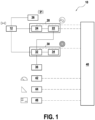
Fig. 1 is a diagram illustrating a work vehicle according to an embodiment; -
Fig. 2 is a flowchart illustrating a driving assistance method according to an embodiment. - A
work vehicle 10 is diagrammatically illustrated inFig. 1 . Systems of thework vehicle 10 which are not relevant to the present disclosure are omitted and may be provided as known in the art. For instance, as a work vehicle, thework vehicle 10 may comprise a work implement, a trailer, etc. - The
work vehicle 10 comprises wheels 12, generally two front wheels and two rear wheels. More or less wheels may be provided. - The
work vehicle 10 comprises aservice brake 20. Theservice brake 20 is configured to decelerate thework vehicle 10 upon actuation. To this end, theservice brake 20 may comprise aservice brake actuator 22 and aservice brake mechanism 24. Theservice brake actuator 22 is actuable by a driver of thework vehicle 10. Theservice brake mechanism 24 receives an input from theservice brake actuator 22 and acts on the wheels 12 (or an axle, or a shaft connected to the wheels 12) accordingly to decelerate thework vehicle 10. Theservice brake 20 itself may be implemented as known per se in the art. For instance, theservice brake actuator 22 may comprise a pedal. For instance, theservice brake mechanism 24 may comprise a hydraulic system. - The
work vehicle 10 further comprises aparking brake 26 distinct from theservice brake 20. Theparking brake 26 is configured, when activated, to keep thework vehicle 10 stopped, irrespective of the actuation of any other system of thework vehicle 10. Theparking brake 26 is actuable by a user of thework vehicle 10. Theparking brake 26 itself may be implemented as known per se in the art. - The
work vehicle 10 further comprises a drivingpower source 36 such as an engine, an electric motor or the like. The drivingpower source 36 may include one or several engines, electric motors or the like, or a combination thereof. Thework vehicle 10 is provided with a transmission 28, such as a power shift transmission, configured to transmit torque from the drivingpower source 36 to the wheels 12. The power shift transmission, as opposed to a continuous variable transmission, enables the user to select a shift among a plurality of discrete shifts, which may be implemented by corresponding gears, as known per se in the art. - In particular, the transmission 28 includes a clutch 30. The clutch 30 may comprise an
engagement mechanism 32, configured to engage or disengage an input component connected to the drivingpower source 36 to/from an output component connected to the wheels 12. When the clutch 30 is engaged (or closed), torque is transmitted from the drivingpower source 36 to the wheels 12 via the transmission 28. Conversely, when the clutch 30 is disengaged (or open), torque from the drivingpower source 36 is not transmitted to the wheels 12 via the transmission 28. - The clutch 30 may comprise a
clutch actuator 34, actuable by a user of thework vehicle 10, and configured to transmit an engagement or disengagement signal to theengagement mechanism 32. For instance, theclutch actuator 34 may be a clutch pedal. - The
work vehicle 10 is provided with a driving assistance system which comprises acontroller 40. Thecontroller 40 may be a dedicated controller or may be common to other systems of thework vehicle 10. - As illustrated in
Fig. 1 , thecontroller 40 may be connected to theservice brake actuator 22. For instance, thecontroller 40 may be configured to receive a value indicative of the stroke of theservice brake actuator 22. Based on that stroke, thecontroller 40 may be configured to determine a slope on which thework vehicle 10 is stopped: for instance, the driver needs to apply a relatively great force to theservice brake actuator 22, hence to move it along a relatively great stroke, in order to maintain thework vehicle 10 stopped on a steep slope. Conversely, the driver needs to apply only a relatively small force to theservice actuator 22, hence to move it along a relatively short stroke, in order to maintain thework vehicle 10 stopped on a gentle slope. - Besides, as illustrated in
Fig. 1 , thecontroller 40 may be connected to theservice brake mechanism 24. For instance, thecontroller 40 may be configured to receive a value indicative of the pressure within theservice brake 20, in particular within theservice brake mechanism 24 or at an interface between theservice brake mechanism 24 and theservice brake actuator 22. Based on that pressure, thecontroller 40 may be configured to determine a slope on which thework vehicle 10 is stopped: for instance, the driver needs a relatively high braking force of theservice brake mechanism 24, hence a relatively high pressure within theservice brake 20, in order to maintain thework vehicle 10 stopped on a steep slope. Conversely, the driver needs a relatively low braking force of theservice brake mechanism 24, hence a relatively low pressure within theservice brake 20, in order to maintain thework vehicle 10 stopped on a gentle slope. - The connection between the
controller 40 and at least one of theservice brake actuator 22 and theservice brake mechanism 24 allows inter alia the controller to determine a slope value, i.e. value representative of the slope of a surface on which the vehicle has stopped. Based on the same principles, thecontroller 40 may be configured to determine that theservice brake 20 has been released based on a stroke of theservice brake actuator 22 and/or on a pressure within theservice brake 20. - Besides, the
controller 40 may be connected to theparking brake 26. Thecontroller 40 is configured to automatically activate or deactivate theparking brake 26 under certain circumstances, as will be detailed hereinafter. Besides, for instance, thecontroller 40 may be configured to automatically activate theparking brake 26 when the driver leaves his seat. - Besides, the
controller 40 may be connected to the clutch 30, in particular to theengagement mechanism 32. Thecontroller 40 is configured to automatically engage or disengage the clutch 30 under certain circumstances, as will be detailed hereinafter. Note that, in this embodiment, the connection between thecontroller 40 and theengagement mechanism 32 bypasses the clutch actuator 34: thus, when engagement or disengagement of the clutch 30 is managed by thecontroller 40, no operation of theclutch actuator 34 is required, which facilitates operation of thework vehicle 10 for the driver. - The
work vehicle 10 may comprise aspeed sensor 42, configured to determine a speed of thework vehicle 10. Direct and indirect speed sensors are known in the art. Thespeed sensor 42 may be configured to output the speed of thework vehicle 10 or to output a comparison result between the speed of thework vehicle 10 and one or more given values, e.g. thresholds. Thecontroller 40 may be connected to thespeed sensor 42 in order to determine whether a speed of thework vehicle 10 is less than a speed threshold. For instance, the speed threshold may be less than 5 kilometers per hour (kph), preferably less than 2 kph, preferably less than 1 kph. - The
work vehicle 10 may comprise anangle sensor 44 configured to output information representative of an angle of the work vehicle with respect to horizontal. Angle sensors for vehicles are known per se in the art. As indicated above, the slope value may be determined by thecontroller 40 through an output of any one of theservice brake actuator 22, theservice brake mechanism 24 and theslope sensor 44, or a combination thereof in order to make the determination more accurate and/or reliable. - The
work vehicle 10 may comprise aninput device 46 for a user to input settings for thecontroller 40. Although theinput device 46 is diagrammatically illustrated as a touch panel, theinput device 46 may be any other means enabling the user to tune settings of thecontroller 40, as mentioned above. Preferably, theinput device 46 is such that it is accessible to a standard user or driver of thework vehicle 10, and not only to shops or dealers. - In this embodiment, the
controller 40 has the hardware configuration of a computer: it comprises inter alia a processor, a memory and communications means with the other devices to which it is connected, as described above and enabling thecontroller 40 to acquire values to these devices. The memory forms a recording medium which can be read by the processor and on which a computer program is stored, the computer program comprising instructions for carrying out the drivingassistance method 100 which will be described with reference toFig. 2 . -
Figure 2 is a flowchart illustrating the driving assistance method 100 (hereinafter "the method") according to an embodiment. As shown in frame E1 ofFig. 2 , as an initial situation, it is assumed that thework vehicle 10 is driving on an upward slope and that the driver wants to stop on that slope. The drivingassistance method 100 is to be applied in real time, repeatedly during operation of thework vehicle 10. - At
step 102, the method evaluates whether theservice brake 20 has been actuated. If theservice brake 20 has not been actuated (NO), the method terminates. Conversely, if theservice brake 20 has been actuated (YES), it should result in a speed decrease of thework vehicle 10 as shown in frame E2, and the method proceeds to step 104. - At
step 104, the method determines whether the work vehicle speed is less than a speed threshold. As discussed above, this determination may be carried out by thecontroller 40, e.g. based on the output of thespeed sensor 42. If the work vehicle speed is greater than the threshold (NO), the method repeatsstep 104, as thework vehicle 10 is still moving too quickly to stop. In other words, the method waits for thework vehicle 10 to be close to stopping, or to be stopped altogether. When thework vehicle 10 has stopped or nearly stopped, i.e. when the work vehicle speed is less than the speed threshold (YES), the method proceeds to step 106. - At
step 106, since the work vehicle speed is less than a speed threshold and the service brake is actuated, thecontroller 40 disengages the clutch 30. Under these circumstances, thework vehicle 10 is brought to a stop. This situation is illustrated in frame E3. Then, the method proceeds to step 108. - At
step 108, thecontroller 40 obtains a slope value representative of the slope of a surface on which thework vehicle 10 has stopped. The slope value may be obtained by the controller as discussed above. Since the ways for obtaining the slope value are independent of the clutch 30, the slope value may be obtained before disengaging the clutch atstep 106, simultaneously thereto, or afterwards as illustrated. - After obtaining the slope value, the
controller 40 determines whether the slope value is greater than a slope threshold atstep 110. If the slope value is greater than the slope threshold at step 110 (YES), the method proceeds to step 112. Otherwise (NO), the method proceeds directly to step 114. - When the clutch has been disengaged at
step 106 and the slope value obtained atstep 108 is greater than a slope threshold, as determined instep 110, thecontroller 40 automatically activates theparking brake 26 atstep 112, as illustrated in frame E4. In other words, when the slope is steeper than the slope threshold, it is determined that theparking brake 26 will be helpful for thework vehicle 10 to resume moving, especially moving forward, and theparking brake 26 is automatically activated by thecontroller 40. The condition on the clutch 30 being disengaged ensures that the parking brake is not activated while the clutch 30 transmits torque from the drivingpower source 26 to the wheels 12, which is likely to lead to stalling. - Conversely, when the slope value is less than the slope threshold, i.e. the slope is relatively gentle, the
controller 40 may not automatically activate theparking brake 26, because theparking brake 26 would not be required for thework vehicle 10 to resume moving, and may even slow down the operation of thework vehicle 10. - After activating the
parking brake 26, or after determining that the slope value is less than the slope threshold, the method proceeds to step 114. Atstep 114, the method determines whether theservice brake 20 has been released. That is, the method determines whether the driver wants thework vehicle 10 to resume moving. Service brake release detection may take place as described above. An arbitrary long time may elapse betweensteps parking brake 26 has been activated or the user keeps theservice brake 20 actuated. As long as the service brake has not been released (NO at step 114),step 114 is repeated. - Otherwise, when the service brake has been released (YES at step 114), the clutch 30 is reengaged by the
controller 40 atstep 116, while maintaining theparking brake 26 activated. This is illustrated in frame E5. - Then, at
step 118, the method checks whether the parking brake was activated. If the parking brake was not activated (NO), then the method terminates, as thework vehicle 10 is capable of moving as soon as the clutch 30 has been reengaged. - Otherwise, if the
parking brake 26 was activated (YES), for instance atstep 112, thecontroller 40 does not deactivate the parking brake immediately, but the method proceeds to step 120, in which thecontroller 40 waits for a predetermined delay after release of theservice brake 20, the predetermined delay being greater than the time required to reengage the clutch 30, or waits for reengagement of the clutch 30 to reach a predetermined value. - For instance, said predetermined value represents a degree of reengagement of the clutch 30, as reengagement is a continuous process between two extreme states, namely the clutch 30 being fully engaged and the clutch 30 being fully disengaged. For example, if the
engagement mechanism 32 of the clutch 30 includes hydraulic components or the like, the predetermined value may be a value of a pressure within theengagement mechanism 32. - The predetermined delay may be tuned to be long enough to enable reengagement of the clutch 30, but short enough in order to prevent stalling of the
work vehicle 10. The starting point of the predetermined delay is the release of theservice brake 20, e.g. when theservice brake actuator 22 is released up to a certain level (i.e. the stroke of theservice brake actuator 22 reaches a threshold), or when a pressure within theservice brake 20 reaches a threshold. In a variant, the starting point of the predetermined delay may be when the reengagement of the clutch 30 reaches a predetermined value. - Either the predetermined delay or the predetermined value may be constant or variable as a function of other parameters, such as the slope value, the parking brake oil temperature where applicable, etc.
- When the predetermined delay after release of the
service brake 20 has elapsed, or when reengagement of the clutch 30 has reached the predetermined value, the driving assistance method proceeds to step 122, in which thecontroller 40 deactivates theparking brake 26. This situation is illustrated by frame E6. Afterwards, the drivingassistance method 100 terminates, as thework vehicle 10 is able to resume moving with a limited or no rollback, as shown in frame E7. - Although the driving
assistance method 100 has been described with reference to thecontroller 40 and the embodiment of thework vehicle 10 as detailed inFig. 1 , the driving assistance method is not limited to that embodiment and may be carried out by other means that thecontroller 40. - In some embodiments, the
input device 46 enables the user to turn on/off said automatic activation and deactivation of theparking brake 26. To this end, theinput device 46 may include a physical switch or the like, or a virtual switch which can be operated by the touch panel or another control present in the work vehicle (joystick, etc.). -
Fig. 2 represents a case in which the automatic activation and deactivation of theparking brake 26 is turned on. When it is turned off, thecontroller 40 may ignoresteps parking brake 26 is not automatically activated, whatever the slope value. Step 118 may be ignored too or may be carried out, but since the parking brake was not activated (NO in step 118), the deactivation thereof is not necessary, and steps 120 and 122 are not carried out in either case. - Besides,
step 110 relies on a comparison with a slope threshold. In some embodiments, the slope threshold may be constant, e.g. set by the manufacturer. In other embodiments, the user may be able to calibrate the slope threshold, e.g. through the input device. - For instance, the
input device 46 may give the user options within a list of preset values (e.g. light, medium and hard sensitivity). The values may themselves be constant, e.g. set by the manufacturer. Thus, the user may select the slope threshold which is the best adapted to his way of driving thework vehicle 10 and to his operational needs. - In another example, the slope threshold may be selected not among discrete values but within a continuous range, for a more accurate calibration. The desired slope threshold may be input manually into the
input device 46. However, theinput device 46 may otherwise be configured to record, as the slope threshold, a value corresponding to an actuation of theservice brake actuator 22. As detailed above, a value corresponding to an actuation of theservice brake actuator 22 may be a stroke value or a pressure value, and is representative of a slope. - Thus, for example, the user may perform a calibration operation of the slope threshold by starting a calibration phase on the
input device 46, actuating theservice brake actuator 22 to a desired level (e.g. stroke or pressure), and to make theinput device 46 record the value at which theservice brake actuator 22 is being actuated. Optionally, theinput device 46, e.g. in case of a touch panel, or another device, may display the recorded value, or even the current value to which theservice brake actuator 22 is being actuated, to facilitate calibration. - Although the present disclosure refers to specific exemplary embodiments, modifications may be provided to these examples without departing from the general scope of the invention as defined by the claims. For instance, although
Fig. 1 illustrates some connections between the different components, the actual connections may be carried out in a different way in order to yield the same functions. As another example, althoughFig. 2 presents steps of the driving assistance method in a certain order, the skilled person can modify this order in a technically appropriate manner while still carrying out the relevant steps of the method. More generally, individual characteristics of the different illustrated/mentioned embodiments may be combined in additional embodiments. Therefore, the description and the drawings should be considered in an illustrative rather than in a restrictive sense.
Claims (13)
- A driving assistance system for a work vehicle (10) comprising a service brake (20) configured to decelerate the work vehicle (10) upon actuation of the service brake (20), a parking brake (26) and a transmission (28) including a clutch (30), the driving assistance system comprising a controller (40) configured to:- disengage the clutch (30) when the work vehicle speed is less than a speed threshold and the service brake (20) is actuated, whereby the work vehicle (10) is brought to a stop;- obtain a slope value representative of the slope of a surface on which the work vehicle (10) has stopped;- automatically activate the parking brake (26) when the clutch (30) has been disengaged and the slope value is greater than a slope threshold;- reengage the clutch (30) when the service brake (20) is released, while maintaining the parking brake (26) activated;- automatically deactivate the parking brake (26) when a predetermined delay after release of the service brake (20) has elapsed, the predetermined delay being greater than the time required to reengage the clutch (30), or when reengagement of the clutch (30) has reached a predetermined value.
- The driving assistance system of claim 1, wherein the controller (40) is configured to determine the slope value based on a stroke of a service brake actuator (22) or on a pressure within the service brake (20).
- The driving assistance system of claim 1 or 2, wherein the work vehicle further comprises an angle sensor (44) configured to output information representative of an angle of the work vehicle (10) with respect to horizontal, and wherein the controller (40) is configured to determine the slope value based on an output of the angle sensor (44).
- The driving assistance system of any one of claims 1 to 3, wherein the controller (40) is configured to determine that the service brake (20) has been released based on a stroke of a service brake actuator (22) or on a pressure within the service brake (20).
- The driving assistance system of any one of claims 1 to 4, wherein the predetermined value is a value of a pressure within an engagement mechanism (32) of the clutch (30).
- The driving assistance system of any one of claims 1 to 5, further comprising an input device (46) configured to enable a user to input settings for the controller (40).
- The driving assistance system of claim 6, wherein the input device (46) is configured to enable a user to turn on/off said automatic activation and deactivation of the parking brake (26).
- The driving assistance system of claim 6 or 7, wherein the input device (46) is configured to enable a user to calibrate the slope threshold.
- The driving assistance system of claim 8, wherein the input device (46) is configured to set the slope threshold at a value chosen by the user within a list of preset values.
- The driving assistance system of claim 8 or 9, wherein the input device (46) is configured to record, as the slope threshold, a value corresponding to an actuation of a service brake actuator (22).
- A driving assistance method (100) for a work vehicle (10) comprising a service brake (20) configured to decelerate the work vehicle upon actuation of the service brake, a parking brake (26) and a transmission (28) including a clutch (30), the driving assistance method comprising:- disengaging the clutch (30) when the work vehicle speed is less than a speed threshold and the service brake (20) is actuated, whereby the work vehicle (10) is brought to a stop;- obtaining a slope value representative of the slope of a surface on which the work vehicle (10) has stopped;- automatically activating the parking brake (26) when the clutch (30) has been disengaged and the slope value is greater than a slope threshold;- reengaging the clutch (30) when the service brake (20) is released, while maintaining the parking brake (26) activated;- automatically deactivating the parking brake (26) when a predetermined delay after release of the service brake (20) has elapsed, the predetermined delay being greater than the time required to reengage the clutch (30), or when reengagement of the clutch (30) has reached a predetermined value.
- A computer program including instructions for executing the steps of the method of claim 11 when said program is executed by a computer.
- A recording medium readable by a computer and having recorded thereon a computer program including instructions for executing the steps of the method of claim 11.
Priority Applications (3)
| Application Number | Priority Date | Filing Date | Title |
|---|---|---|---|
| EP22305270.5A EP4242495B1 (en) | 2022-03-10 | 2022-03-10 | Driving assistance system and method |
| JP2023018964A JP2023133151A (en) | 2022-03-10 | 2023-02-10 | Driving support system and driving support method |
| US18/111,030 US12415485B2 (en) | 2022-03-10 | 2023-02-17 | Driving assistance system and method |
Applications Claiming Priority (1)
| Application Number | Priority Date | Filing Date | Title |
|---|---|---|---|
| EP22305270.5A EP4242495B1 (en) | 2022-03-10 | 2022-03-10 | Driving assistance system and method |
Publications (2)
| Publication Number | Publication Date |
|---|---|
| EP4242495A1 true EP4242495A1 (en) | 2023-09-13 |
| EP4242495B1 EP4242495B1 (en) | 2025-03-26 |
Family
ID=80952478
Family Applications (1)
| Application Number | Title | Priority Date | Filing Date |
|---|---|---|---|
| EP22305270.5A Active EP4242495B1 (en) | 2022-03-10 | 2022-03-10 | Driving assistance system and method |
Country Status (3)
| Country | Link |
|---|---|
| US (1) | US12415485B2 (en) |
| EP (1) | EP4242495B1 (en) |
| JP (1) | JP2023133151A (en) |
Families Citing this family (1)
| Publication number | Priority date | Publication date | Assignee | Title |
|---|---|---|---|---|
| DE102022213831A1 (en) * | 2022-12-19 | 2024-06-20 | Zf Cv Systems Global Gmbh | Method for braking control of a vehicle combination and braking control system for operating this method |
Citations (4)
| Publication number | Priority date | Publication date | Assignee | Title |
|---|---|---|---|---|
| US20100094513A1 (en) * | 2007-03-16 | 2010-04-15 | Zf Friedrichshafen Ag | Method for starting control unit of a motor vehicle |
| US20170219092A1 (en) * | 2016-01-29 | 2017-08-03 | CNH Industrial America, LLC | System and method for controlling a work vehicle transmission based on the detection of unintended vehicle motion |
| EP3470707A1 (en) * | 2017-10-13 | 2019-04-17 | CNH Industrial Italia S.p.A. | Method for controlling a transmission provided with brake to clutch functionality |
| US20210380084A1 (en) * | 2020-06-04 | 2021-12-09 | Caterpillar Underground Mining Pty. Ltd. | Method and control system for controlling machine |
Family Cites Families (41)
| Publication number | Priority date | Publication date | Assignee | Title |
|---|---|---|---|---|
| JPS59140153A (en) * | 1983-01-31 | 1984-08-11 | Mazda Motor Corp | Motor-driven parking brake device |
| DE19950034B4 (en) * | 1999-10-16 | 2019-09-26 | Robert Bosch Gmbh | Method and device for controlling a brake system |
| US6530450B2 (en) * | 2000-08-09 | 2003-03-11 | Deluca Michael | Fault reactive securely stopped vehicle method and apparatus |
| DE10063063A1 (en) * | 2000-12-18 | 2002-06-20 | Lucas Varity Gmbh | Method and system for controlling braking equipment that can be activated when a motor vehicle is stationary |
| US7074161B2 (en) * | 2001-05-08 | 2006-07-11 | Continental Teves, Inc. | Method for assisting a vehicle to start on a slope |
| DE10135744A1 (en) * | 2001-07-21 | 2003-02-06 | Zahnradfabrik Friedrichshafen | Arrangement for preventing vehicle from rolling backwards, has brake that acts on vehicle gearbox operated while vehicle is stationary or almost stationary in addition to vehicle brakes |
| FR2828450B1 (en) * | 2001-08-07 | 2003-10-03 | Renault | STARTING ASSISTANCE DEVICE FOR A MOTOR VEHICLE |
| US7032697B2 (en) * | 2002-05-30 | 2006-04-25 | Hyeongcheol Lee | Drive control system for vehicles with an auxiliary driving system |
| DE10244024A1 (en) * | 2002-09-21 | 2004-04-01 | Zf Friedrichshafen Ag | Method and device for preventing unintentional rolling away of a stationary vehicle |
| DE10250719A1 (en) * | 2002-10-31 | 2004-05-19 | Robert Bosch Gmbh | Method and device for controlling the brake system of a motor vehicle |
| SE524510C2 (en) * | 2002-12-30 | 2004-08-17 | Volvo Lastvagnar Ab | Method and device for starting uphill |
| US7136735B2 (en) * | 2003-10-02 | 2006-11-14 | General Motors Corporation | Adaptive hill hold for automobile applications by redundant clutch apply |
| DE102004017635A1 (en) * | 2004-04-10 | 2005-10-27 | Daimlerchrysler Ag | hill holder |
| DE102004030795B4 (en) * | 2004-06-25 | 2020-09-17 | Robert Bosch Gmbh | Rollback limitation for a motor vehicle |
| DE102004039866B3 (en) * | 2004-08-17 | 2006-02-09 | Siemens Ag | Control system for the parking brake of a brake system of a motor vehicle |
| WO2006067125A1 (en) * | 2004-12-20 | 2006-06-29 | Continental Teves Ag & Co. Ohg | Starting-traction control |
| JP2006224743A (en) * | 2005-02-16 | 2006-08-31 | Advics:Kk | Braking force holding control device |
| JP2007309486A (en) * | 2006-05-22 | 2007-11-29 | Toyota Motor Corp | Vehicle start control device |
| DE102007006700B4 (en) * | 2007-02-10 | 2020-09-24 | Bayerische Motoren Werke Aktiengesellschaft | Brake control system for motor vehicles |
| FR2914894B1 (en) * | 2007-04-12 | 2009-07-17 | Peugeot Citroen Automobiles Sa | DRIVING ASSISTANCE SYSTEM IN THE SLOPES FOR A MOTOR VEHICLE |
| FR2915158B1 (en) * | 2007-04-19 | 2009-10-02 | Renault Sas | METHOD FOR ASSISTING AT THE SIDE MANEUVER FOR A VEHICLE |
| FR2920381B1 (en) * | 2007-08-31 | 2009-10-30 | Renault Sas | SYSTEM AND METHOD FOR CONTROLLING THE LOOSENING OF AN AUTOMATIC PARKING BRAKE DEVICE ONBOARD A MOTOR VEHICLE |
| FR2921453B1 (en) * | 2007-09-25 | 2010-02-26 | Renault Sas | METHOD FOR STARTING ASSISTANCE ON THE SIDE OF A MOTORIZED VEHICLE |
| DE102008020844B4 (en) * | 2008-04-25 | 2024-09-26 | Bayerische Motoren Werke Aktiengesellschaft | Locking function for temporarily holding a ready-to-use motor vehicle at a standstill |
| US8078378B2 (en) * | 2008-12-31 | 2011-12-13 | Volvo Group North America, Inc. | Hill start assist system |
| DE102010002626A1 (en) * | 2010-03-05 | 2011-09-08 | Continental Teves Ag & Co. Ohg | Operating method for a motor vehicle, in particular comprising an electronically controlled and / or regulated parking brake system |
| DE102010028074A1 (en) * | 2010-04-22 | 2011-10-27 | Zf Friedrichshafen Ag | Method for assisting the driver of a motor vehicle during startup operations |
| CN103140394B (en) * | 2010-09-23 | 2015-06-24 | 大陆-特韦斯贸易合伙股份公司及两合公司 | Retaining function for a motor vehicle |
| DE102010050101B4 (en) * | 2010-10-29 | 2019-11-21 | Knorr-Bremse Systeme für Nutzfahrzeuge GmbH | Pressure-medium-actuated braking device of a vehicle with implemented in a brake control control routines Berggasfahrhilfe- or creep suppression function |
| JP5737740B2 (en) * | 2010-11-24 | 2015-06-17 | Udトラックス株式会社 | Clutch disengagement control mechanism for mechanical automatic transmission |
| US8543303B2 (en) * | 2011-02-01 | 2013-09-24 | Rollfree Tek, Llc | Anti-rollback control system for hybrid and conventional powertrain vehicles |
| JP5477316B2 (en) * | 2011-03-16 | 2014-04-23 | 株式会社アドヴィックス | Vehicle sliding-down state determination device and vehicle control device including the same |
| US9206562B2 (en) * | 2012-03-08 | 2015-12-08 | Caterpillar Paving Products Inc. | Grade propulsion system and method |
| GB2516498B (en) * | 2013-07-25 | 2017-06-14 | Jaguar Land Rover Ltd | Vehicle control system and method |
| JP2017114244A (en) * | 2015-12-22 | 2017-06-29 | ローベルト ボッシュ ゲゼルシャフト ミット ベシュレンクテル ハフツング | Control apparatus and control method |
| US9821778B2 (en) * | 2016-02-23 | 2017-11-21 | Honda Motor Co., Ltd. | Vehicle control system |
| JP2017178142A (en) * | 2016-03-31 | 2017-10-05 | 株式会社小松製作所 | Work vehicle |
| US10421456B2 (en) * | 2017-02-20 | 2019-09-24 | Ford Global Technologies, Llc | Customized electric parking brake response to maintain engine auto-stop with brake released |
| JP7242435B2 (en) * | 2019-06-11 | 2023-03-20 | 株式会社クボタ | work vehicle |
| EP4033124A4 (en) * | 2019-09-18 | 2023-08-23 | Kubota Corporation | COMMERCIAL VEHICLE |
| US11623619B2 (en) * | 2019-12-10 | 2023-04-11 | Bendix Commercial Vehicle Systems Llc | Parking brake apparatus and method therefor |
-
2022
- 2022-03-10 EP EP22305270.5A patent/EP4242495B1/en active Active
-
2023
- 2023-02-10 JP JP2023018964A patent/JP2023133151A/en active Pending
- 2023-02-17 US US18/111,030 patent/US12415485B2/en active Active
Patent Citations (5)
| Publication number | Priority date | Publication date | Assignee | Title |
|---|---|---|---|---|
| US20100094513A1 (en) * | 2007-03-16 | 2010-04-15 | Zf Friedrichshafen Ag | Method for starting control unit of a motor vehicle |
| US20170219092A1 (en) * | 2016-01-29 | 2017-08-03 | CNH Industrial America, LLC | System and method for controlling a work vehicle transmission based on the detection of unintended vehicle motion |
| US10316959B2 (en) | 2016-01-29 | 2019-06-11 | Cnh Industrial America Llc | System and method for controlling a work vehicle transmission based on the detection of unintended vehicle motion |
| EP3470707A1 (en) * | 2017-10-13 | 2019-04-17 | CNH Industrial Italia S.p.A. | Method for controlling a transmission provided with brake to clutch functionality |
| US20210380084A1 (en) * | 2020-06-04 | 2021-12-09 | Caterpillar Underground Mining Pty. Ltd. | Method and control system for controlling machine |
Also Published As
| Publication number | Publication date |
|---|---|
| JP2023133151A (en) | 2023-09-22 |
| EP4242495B1 (en) | 2025-03-26 |
| US20230286475A1 (en) | 2023-09-14 |
| US12415485B2 (en) | 2025-09-16 |
Similar Documents
| Publication | Publication Date | Title |
|---|---|---|
| US7407463B2 (en) | Method and system for controlling a braking system equipped with an electric parking brake | |
| US8224540B2 (en) | Apparatus and method for inching using a continuously variable transmission | |
| US11040724B2 (en) | Vehicle driving force control apparatus | |
| US6959969B2 (en) | System and method for controlling a brake | |
| EP2544930B1 (en) | Method and computer programme product for control of a vehicle power train and service brake system | |
| JPH0217734B2 (en) | ||
| US12415485B2 (en) | Driving assistance system and method | |
| JP6721573B2 (en) | Manual auxiliary drive and braking torque control | |
| KR100852991B1 (en) | Start-off prevention system and brake control method when braking the work machine | |
| US11472410B2 (en) | System and method for actuator initiated launch or line lock control | |
| US11180901B2 (en) | Work vehicle | |
| EP2079602B1 (en) | A system and a method for controlling an operation of starting a motor vehicle standing still. | |
| US20140324258A1 (en) | Speed Control System for Motor Vehicles | |
| US20080021627A1 (en) | Method And Computer Program At A Vehicle For Adjusting The Distance To A Vehicle Ahead | |
| CN108349502B (en) | Driver assistance device for a motor vehicle and method for operating a motor vehicle | |
| EP2021215B1 (en) | Operation control system | |
| GB2555166B (en) | An apparatus, method and computer program for providing parking assistance within a vehicle | |
| US7344012B2 (en) | Transmission brake control assembly | |
| US12606131B2 (en) | Vehicle control device | |
| WO2006098672A1 (en) | A system and a method for controlling the operation of a vehicle engine | |
| US11473633B2 (en) | Method for controlling an automated starter clutch in a drive train of a motor vehicle | |
| JP2569981B2 (en) | Braking force holding device | |
| JP4396485B2 (en) | Vehicle control device | |
| JPH0375774B2 (en) | ||
| US20180347646A1 (en) | Actuation of a clutch of a motor vehicle |
Legal Events
| Date | Code | Title | Description |
|---|---|---|---|
| PUAI | Public reference made under article 153(3) epc to a published international application that has entered the european phase |
Free format text: ORIGINAL CODE: 0009012 |
|
| STAA | Information on the status of an ep patent application or granted ep patent |
Free format text: STATUS: THE APPLICATION HAS BEEN PUBLISHED |
|
| AK | Designated contracting states |
Kind code of ref document: A1 Designated state(s): AL AT BE BG CH CY CZ DE DK EE ES FI FR GB GR HR HU IE IS IT LI LT LU LV MC MK MT NL NO PL PT RO RS SE SI SK SM TR |
|
| STAA | Information on the status of an ep patent application or granted ep patent |
Free format text: STATUS: REQUEST FOR EXAMINATION WAS MADE |
|
| 17P | Request for examination filed |
Effective date: 20231012 |
|
| RBV | Designated contracting states (corrected) |
Designated state(s): AL AT BE BG CH CY CZ DE DK EE ES FI FR GB GR HR HU IE IS IT LI LT LU LV MC MK MT NL NO PL PT RO RS SE SI SK SM TR |
|
| GRAP | Despatch of communication of intention to grant a patent |
Free format text: ORIGINAL CODE: EPIDOSNIGR1 |
|
| STAA | Information on the status of an ep patent application or granted ep patent |
Free format text: STATUS: GRANT OF PATENT IS INTENDED |
|
| GRAJ | Information related to disapproval of communication of intention to grant by the applicant or resumption of examination proceedings by the epo deleted |
Free format text: ORIGINAL CODE: EPIDOSDIGR1 |
|
| STAA | Information on the status of an ep patent application or granted ep patent |
Free format text: STATUS: REQUEST FOR EXAMINATION WAS MADE |
|
| INTG | Intention to grant announced |
Effective date: 20240917 |
|
| GRAP | Despatch of communication of intention to grant a patent |
Free format text: ORIGINAL CODE: EPIDOSNIGR1 |
|
| STAA | Information on the status of an ep patent application or granted ep patent |
Free format text: STATUS: GRANT OF PATENT IS INTENDED |
|
| INTC | Intention to grant announced (deleted) | ||
| INTG | Intention to grant announced |
Effective date: 20241025 |
|
| GRAS | Grant fee paid |
Free format text: ORIGINAL CODE: EPIDOSNIGR3 |
|
| GRAA | (expected) grant |
Free format text: ORIGINAL CODE: 0009210 |
|
| STAA | Information on the status of an ep patent application or granted ep patent |
Free format text: STATUS: THE PATENT HAS BEEN GRANTED |
|
| AK | Designated contracting states |
Kind code of ref document: B1 Designated state(s): AL AT BE BG CH CY CZ DE DK EE ES FI FR GB GR HR HU IE IS IT LI LT LU LV MC MK MT NL NO PL PT RO RS SE SI SK SM TR |
|
| REG | Reference to a national code |
Ref country code: GB Ref legal event code: FG4D |
|
| REG | Reference to a national code |
Ref country code: CH Ref legal event code: EP |
|
| REG | Reference to a national code |
Ref country code: DE Ref legal event code: R096 Ref document number: 602022012231 Country of ref document: DE |
|
| REG | Reference to a national code |
Ref country code: IE Ref legal event code: FG4D |
|
| PG25 | Lapsed in a contracting state [announced via postgrant information from national office to epo] |
Ref country code: RS Free format text: LAPSE BECAUSE OF FAILURE TO SUBMIT A TRANSLATION OF THE DESCRIPTION OR TO PAY THE FEE WITHIN THE PRESCRIBED TIME-LIMIT Effective date: 20250626 |
|
| PG25 | Lapsed in a contracting state [announced via postgrant information from national office to epo] |
Ref country code: FI Free format text: LAPSE BECAUSE OF FAILURE TO SUBMIT A TRANSLATION OF THE DESCRIPTION OR TO PAY THE FEE WITHIN THE PRESCRIBED TIME-LIMIT Effective date: 20250326 |
|
| REG | Reference to a national code |
Ref country code: LT Ref legal event code: MG9D |
|
| PG25 | Lapsed in a contracting state [announced via postgrant information from national office to epo] |
Ref country code: NO Free format text: LAPSE BECAUSE OF FAILURE TO SUBMIT A TRANSLATION OF THE DESCRIPTION OR TO PAY THE FEE WITHIN THE PRESCRIBED TIME-LIMIT Effective date: 20250626 |
|
| PG25 | Lapsed in a contracting state [announced via postgrant information from national office to epo] |
Ref country code: HR Free format text: LAPSE BECAUSE OF FAILURE TO SUBMIT A TRANSLATION OF THE DESCRIPTION OR TO PAY THE FEE WITHIN THE PRESCRIBED TIME-LIMIT Effective date: 20250326 |
|
| PG25 | Lapsed in a contracting state [announced via postgrant information from national office to epo] |
Ref country code: LV Free format text: LAPSE BECAUSE OF FAILURE TO SUBMIT A TRANSLATION OF THE DESCRIPTION OR TO PAY THE FEE WITHIN THE PRESCRIBED TIME-LIMIT Effective date: 20250326 |
|
| PG25 | Lapsed in a contracting state [announced via postgrant information from national office to epo] |
Ref country code: BG Free format text: LAPSE BECAUSE OF FAILURE TO SUBMIT A TRANSLATION OF THE DESCRIPTION OR TO PAY THE FEE WITHIN THE PRESCRIBED TIME-LIMIT Effective date: 20250326 Ref country code: GR Free format text: LAPSE BECAUSE OF FAILURE TO SUBMIT A TRANSLATION OF THE DESCRIPTION OR TO PAY THE FEE WITHIN THE PRESCRIBED TIME-LIMIT Effective date: 20250627 |
|
| REG | Reference to a national code |
Ref country code: NL Ref legal event code: MP Effective date: 20250326 |
|
| PG25 | Lapsed in a contracting state [announced via postgrant information from national office to epo] |
Ref country code: NL Free format text: LAPSE BECAUSE OF FAILURE TO SUBMIT A TRANSLATION OF THE DESCRIPTION OR TO PAY THE FEE WITHIN THE PRESCRIBED TIME-LIMIT Effective date: 20250326 |
|
| PG25 | Lapsed in a contracting state [announced via postgrant information from national office to epo] |
Ref country code: SE Free format text: LAPSE BECAUSE OF FAILURE TO SUBMIT A TRANSLATION OF THE DESCRIPTION OR TO PAY THE FEE WITHIN THE PRESCRIBED TIME-LIMIT Effective date: 20250326 |
|
| REG | Reference to a national code |
Ref country code: AT Ref legal event code: MK05 Ref document number: 1779263 Country of ref document: AT Kind code of ref document: T Effective date: 20250326 |
|
| PG25 | Lapsed in a contracting state [announced via postgrant information from national office to epo] |
Ref country code: SM Free format text: LAPSE BECAUSE OF FAILURE TO SUBMIT A TRANSLATION OF THE DESCRIPTION OR TO PAY THE FEE WITHIN THE PRESCRIBED TIME-LIMIT Effective date: 20250326 |
|
| PG25 | Lapsed in a contracting state [announced via postgrant information from national office to epo] |
Ref country code: PT Free format text: LAPSE BECAUSE OF FAILURE TO SUBMIT A TRANSLATION OF THE DESCRIPTION OR TO PAY THE FEE WITHIN THE PRESCRIBED TIME-LIMIT Effective date: 20250728 Ref country code: ES Free format text: LAPSE BECAUSE OF FAILURE TO SUBMIT A TRANSLATION OF THE DESCRIPTION OR TO PAY THE FEE WITHIN THE PRESCRIBED TIME-LIMIT Effective date: 20250326 |
|
| PG25 | Lapsed in a contracting state [announced via postgrant information from national office to epo] |
Ref country code: IT Free format text: LAPSE BECAUSE OF FAILURE TO SUBMIT A TRANSLATION OF THE DESCRIPTION OR TO PAY THE FEE WITHIN THE PRESCRIBED TIME-LIMIT Effective date: 20250326 Ref country code: PL Free format text: LAPSE BECAUSE OF FAILURE TO SUBMIT A TRANSLATION OF THE DESCRIPTION OR TO PAY THE FEE WITHIN THE PRESCRIBED TIME-LIMIT Effective date: 20250326 |
|
| PG25 | Lapsed in a contracting state [announced via postgrant information from national office to epo] |
Ref country code: AT Free format text: LAPSE BECAUSE OF FAILURE TO SUBMIT A TRANSLATION OF THE DESCRIPTION OR TO PAY THE FEE WITHIN THE PRESCRIBED TIME-LIMIT Effective date: 20250326 |
|
| PG25 | Lapsed in a contracting state [announced via postgrant information from national office to epo] |
Ref country code: EE Free format text: LAPSE BECAUSE OF FAILURE TO SUBMIT A TRANSLATION OF THE DESCRIPTION OR TO PAY THE FEE WITHIN THE PRESCRIBED TIME-LIMIT Effective date: 20250326 |
|
| PG25 | Lapsed in a contracting state [announced via postgrant information from national office to epo] |
Ref country code: RO Free format text: LAPSE BECAUSE OF FAILURE TO SUBMIT A TRANSLATION OF THE DESCRIPTION OR TO PAY THE FEE WITHIN THE PRESCRIBED TIME-LIMIT Effective date: 20250326 |
|
| PG25 | Lapsed in a contracting state [announced via postgrant information from national office to epo] |
Ref country code: SK Free format text: LAPSE BECAUSE OF FAILURE TO SUBMIT A TRANSLATION OF THE DESCRIPTION OR TO PAY THE FEE WITHIN THE PRESCRIBED TIME-LIMIT Effective date: 20250326 |
|
| PG25 | Lapsed in a contracting state [announced via postgrant information from national office to epo] |
Ref country code: IS Free format text: LAPSE BECAUSE OF FAILURE TO SUBMIT A TRANSLATION OF THE DESCRIPTION OR TO PAY THE FEE WITHIN THE PRESCRIBED TIME-LIMIT Effective date: 20250726 |
|
| REG | Reference to a national code |
Ref country code: DE Ref legal event code: R097 Ref document number: 602022012231 Country of ref document: DE |
|
| PG25 | Lapsed in a contracting state [announced via postgrant information from national office to epo] |
Ref country code: DK Free format text: LAPSE BECAUSE OF FAILURE TO SUBMIT A TRANSLATION OF THE DESCRIPTION OR TO PAY THE FEE WITHIN THE PRESCRIBED TIME-LIMIT Effective date: 20250326 |
|
| PG25 | Lapsed in a contracting state [announced via postgrant information from national office to epo] |
Ref country code: CZ Free format text: LAPSE BECAUSE OF FAILURE TO SUBMIT A TRANSLATION OF THE DESCRIPTION OR TO PAY THE FEE WITHIN THE PRESCRIBED TIME-LIMIT Effective date: 20250326 |
|
| PLBE | No opposition filed within time limit |
Free format text: ORIGINAL CODE: 0009261 |
|
| STAA | Information on the status of an ep patent application or granted ep patent |
Free format text: STATUS: NO OPPOSITION FILED WITHIN TIME LIMIT |
|
| REG | Reference to a national code |
Ref country code: CH Ref legal event code: L10 Free format text: ST27 STATUS EVENT CODE: U-0-0-L10-L00 (AS PROVIDED BY THE NATIONAL OFFICE) Effective date: 20260211 |
|
| 26N | No opposition filed |
Effective date: 20260105 |
|
| PGFP | Annual fee paid to national office [announced via postgrant information from national office to epo] |
Ref country code: DE Payment date: 20260128 Year of fee payment: 5 |
|
| PGFP | Annual fee paid to national office [announced via postgrant information from national office to epo] |
Ref country code: FR Payment date: 20260209 Year of fee payment: 5 |