EP4242488A1 - Chain - Google Patents
Chain Download PDFInfo
- Publication number
- EP4242488A1 EP4242488A1 EP23160482.8A EP23160482A EP4242488A1 EP 4242488 A1 EP4242488 A1 EP 4242488A1 EP 23160482 A EP23160482 A EP 23160482A EP 4242488 A1 EP4242488 A1 EP 4242488A1
- Authority
- EP
- European Patent Office
- Prior art keywords
- chain
- pins
- bushings
- sliding
- surface layer
- Prior art date
- Legal status (The legal status is an assumption and is not a legal conclusion. Google has not performed a legal analysis and makes no representation as to the accuracy of the status listed.)
- Granted
Links
Images




Classifications
-
- F—MECHANICAL ENGINEERING; LIGHTING; HEATING; WEAPONS; BLASTING
- F16—ENGINEERING ELEMENTS AND UNITS; GENERAL MEASURES FOR PRODUCING AND MAINTAINING EFFECTIVE FUNCTIONING OF MACHINES OR INSTALLATIONS; THERMAL INSULATION IN GENERAL
- F16G—BELTS, CABLES, OR ROPES, PREDOMINANTLY USED FOR DRIVING PURPOSES; CHAINS; FITTINGS PREDOMINANTLY USED THEREFOR
- F16G13/00—Chains
- F16G13/02—Driving-chains
- F16G13/06—Driving-chains with links connected by parallel driving-pins with or without rollers so-called open links
-
- C—CHEMISTRY; METALLURGY
- C21—METALLURGY OF IRON
- C21D—MODIFYING THE PHYSICAL STRUCTURE OF FERROUS METALS; GENERAL DEVICES FOR HEAT TREATMENT OF FERROUS OR NON-FERROUS METALS OR ALLOYS; MAKING METAL MALLEABLE, e.g. BY DECARBURISATION OR TEMPERING
- C21D1/00—General methods or devices for heat treatment, e.g. annealing, hardening, quenching or tempering
- C21D1/06—Surface hardening
-
- C—CHEMISTRY; METALLURGY
- C21—METALLURGY OF IRON
- C21D—MODIFYING THE PHYSICAL STRUCTURE OF FERROUS METALS; GENERAL DEVICES FOR HEAT TREATMENT OF FERROUS OR NON-FERROUS METALS OR ALLOYS; MAKING METAL MALLEABLE, e.g. BY DECARBURISATION OR TEMPERING
- C21D9/00—Heat treatment, e.g. annealing, hardening, quenching or tempering, adapted for particular articles; Furnaces therefor
- C21D9/0087—Heat treatment, e.g. annealing, hardening, quenching or tempering, adapted for particular articles; Furnaces therefor for chains, for chain links
-
- F—MECHANICAL ENGINEERING; LIGHTING; HEATING; WEAPONS; BLASTING
- F16—ENGINEERING ELEMENTS AND UNITS; GENERAL MEASURES FOR PRODUCING AND MAINTAINING EFFECTIVE FUNCTIONING OF MACHINES OR INSTALLATIONS; THERMAL INSULATION IN GENERAL
- F16G—BELTS, CABLES, OR ROPES, PREDOMINANTLY USED FOR DRIVING PURPOSES; CHAINS; FITTINGS PREDOMINANTLY USED THEREFOR
- F16G13/00—Chains
- F16G13/02—Driving-chains
- F16G13/08—Driving-chains with links closely interposed on the joint pins
-
- F—MECHANICAL ENGINEERING; LIGHTING; HEATING; WEAPONS; BLASTING
- F16—ENGINEERING ELEMENTS AND UNITS; GENERAL MEASURES FOR PRODUCING AND MAINTAINING EFFECTIVE FUNCTIONING OF MACHINES OR INSTALLATIONS; THERMAL INSULATION IN GENERAL
- F16G—BELTS, CABLES, OR ROPES, PREDOMINANTLY USED FOR DRIVING PURPOSES; CHAINS; FITTINGS PREDOMINANTLY USED THEREFOR
- F16G15/00—Chain couplings, Shackles; Chain joints; Chain links; Chain bushes
- F16G15/12—Chain links
-
- C—CHEMISTRY; METALLURGY
- C22—METALLURGY; FERROUS OR NON-FERROUS ALLOYS; TREATMENT OF ALLOYS OR NON-FERROUS METALS
- C22C—ALLOYS
- C22C38/00—Ferrous alloys, e.g. steel alloys
-
- F—MECHANICAL ENGINEERING; LIGHTING; HEATING; WEAPONS; BLASTING
- F16—ENGINEERING ELEMENTS AND UNITS; GENERAL MEASURES FOR PRODUCING AND MAINTAINING EFFECTIVE FUNCTIONING OF MACHINES OR INSTALLATIONS; THERMAL INSULATION IN GENERAL
- F16G—BELTS, CABLES, OR ROPES, PREDOMINANTLY USED FOR DRIVING PURPOSES; CHAINS; FITTINGS PREDOMINANTLY USED THEREFOR
- F16G13/00—Chains
- F16G13/02—Driving-chains
- F16G13/06—Driving-chains with links connected by parallel driving-pins with or without rollers so-called open links
- F16G13/07—Driving-chains with links connected by parallel driving-pins with or without rollers so-called open links the links being of identical shape, e.g. cranked
Definitions
- the present invention relates to a chain that includes at least a plurality of link plates and a plurality of pins as the chain components.
- Chains used in a chain drive system include roller chains, bushing chains, and silent chains, which are made up of inner links and outer links respectively including a plurality of inner plates and outer plates arranged in the chain width direction, these inner links and outer links alternately and pivotably coupled together by pins along the longitudinal direction of the chain.
- Japanese Patent Application Publication No. 2008-281027 describes a chain having pins covered with a chromium or vanadium carbide layer for better resistance to wear-induced elongation under the use of lubricating oil containing carbon soot, and for retarding abnormal wear caused by oil film shortage.
- Chain components without surface hardening have a sliding surface hardness (HV) in the range of 800 to 1000, for example. Therefore, contaminants such as silicon or alumina particles, if contained in the lubricating oil, may accelerate wear on the sliding surfaces of the chain components having a lower hardness than silicon or alumina, and may cause chain elongation.
- HV sliding surface hardness
- the present invention was made in view of the circumstances described above, its object being to provide a chain that has excellent wear resistance and can minimize chain elongation, reduce vibration and noise, and improve drive efficiency.
- the present invention solves the above problem by providing a chain including at least a plurality of link plates and a plurality of pins as chain components, the pins and mutually sliding chain components sliding against the pins being formed with a hardened surface layer containing one of Cr carbide, Ti carbide, V carbide, Nb carbide, Cr nitride, Ti nitride, V nitride, and Nb nitride on part or all of respective sliding surfaces.
- the pins and mutually sliding chain components sliding against the pins are formed with a hardened surface layer containing one of Cr carbide, Ti carbide, V carbide, Nb carbide, Cr nitride, Ti nitride, V nitride, and Nb nitride on part or all of respective sliding surfaces.
- the hardened surface layer minimizes wear caused by the sliding contact between the pins and the mutually sliding chain components, and thus can retard chain elongation.
- Minimized chain elongation ensures correct meshing with sprockets, which prevents loss of drive efficiency and reduces vibration and noise.
- any physical contaminants that got in between the sliding surfaces of pins and mutually sliding chain components can be readily released, and lubricating oil can be retained more easily on the sliding surface of the mutually sliding chain components. This can further improve the wear resistance of the pins and the mutually sliding chain components, and help retard chain elongation more reliably.
- the configuration set forth in claim 4 further ensures the effect of retarding chain elongation by improved wear resistance.
- wear on the sliding surfaces of the pins and mutually sliding chain components caused by physical contaminants can be reliably prevented even when contaminants such as silicon or alumina particles for example are contained in the lubricating oil, because the hardened surface layer of the pins and the hardened surface layer of the mutually sliding chain components each have a higher hardness than the contaminants.
- the bushings retain a certain sliding surface roughness even after some wear due to the sliding contact with the pins so that the bushings can provide the effect of releasing contaminants that get in between the pins and the bushings and the effect of retaining lubricating oil on the sliding surface of the bushings for a prolonged time.
- the intended wear resistance can be maintained.
- FIG. 1 is a cross-sectional view illustrating part of one configuration example of a chain according to a first embodiment of the present invention.
- This chain 100 is configured as a roller chain and includes outer link plates 111, inner link plates 121, pins 115, bushings 125, and rollers 130 as the chain components.
- the chain 100 includes: a plurality of outer links 110 each made up of a pair of left and right outer link plates 111 and a pair of front and rear pins 115 coupled thereto; a plurality of inner links 120 each made up of a pair of left and right inner link plates 121 disposed between the pair of left and right outer link plates 111 and a pair of front and rear cylindrical bushings 125 coupled thereto; and rollers 130 fitted on the bushings 125.
- These plurality of outer links 110 and inner links 120 are alternately and pivotably coupled together along the longitudinal direction of the chain by the pins 115 inserted in the bushings 125.
- the pins 115, and bushings 125 which are mutually sliding chain components sliding against the pins 115, are formed with hardened surface layers 116 and 126 as shown in FIG. 2 containing one of Cr carbide, Ti carbide, V carbide, Nb carbide, Cr nitride, Ti nitride, V nitride, and Nb nitride on their entire sliding surfaces.
- the pins 115 in the chain 100 of this embodiment have the hardened surface layer 116 covering their entire outer circumferential surface
- the hardened surface layer 116 may cover at least part of the outer circumferential surface of the pins 115 that slides against the inner circumferential surface of the bushings 125.
- the bushings 125 have the hardened surface layer 126 covering their inner circumferential surface, which is the sliding surface that slides against the outer circumferential surface of the pins 115.
- the hardened surface layer may also be provided to both end faces of the bushings 125 that make contact with inner side faces of the outer link plates 111, and to an outer circumferential surface of the bushings 125 that makes contact with an inner circumferential surface of the rollers 130.
- the hardened surface layers 116 and 126 should preferably have a thickness of 2 um or more and 30 um or less, for example, for ensuring good wear resistance and improved resistance to wear-induced chain elongation.
- the hardened surface layer 116 of the pins 115 should preferably have a smaller sliding surface roughness than that of the hardened surface layer 126 of the bushings 125.
- the sliding surface roughness Rk of the hardened surface layer 116 of the pins 115 should preferably be 0.04 um to 0.30 um
- the sliding surface roughness Rk of the hardened surface layer 126 of the bushings 125 should preferably be 0.8 um to 2.0 um.
- the sliding surface roughness Rk here refers to the effective load roughness as defined by JIS B0671-2:2002. Other surface roughness parameters may be employed, as long as the ranges of Rk values specified above are substantially covered.
- the hardened surface layer 116 of the pins 115 and the hardened surface layer 126 of the bushings 125 should preferably each have a sliding surface hardness (HV) of 1600 or more and 3500 or less. This hardness is higher than that of silicon or alumina, so that abrasive wear on the respective sliding surfaces of the pins 115 and bushings 125 caused by physical contaminants can be reliably prevented even when high-hardness contaminants such as silicon or alumina particles are contained in the lubricating oil.
- HV sliding surface hardness
- the bushings 125 in the chain 100 of this embodiment are cylindrical, with its inner circumferential surface conforming to a cylindrical circumferential surface.
- the bushings 125 should have a concave inner circumferential surface as shown in FIG. 3 .
- This configuration allows the bushing 125 to keep its sliding surface roughness even after some wear caused by the sliding contact with the pin 115, and therefore any physical contaminants that got in between the outer circumferential surface of the pins 115 and the inner circumferential surface of the bushings 125 can be readily released, and the lubricating oil can be retained more easily on the sliding surface of the bushings 125.
- the wear resistance of the pins 115 and bushings 125 can thus be further improved.
- the chain according to the present invention may be configured as a bushing chain as shown in FIG. 4 and FIG. 5 , which is similar to the roller chain according to the first embodiment but without the rollers on the bushings 125 of the inner links 120.
- the components in FIG. 4 and FIG. 5 that are the same as those of the roller chain according to the first embodiment are given the same reference numerals for convenience of description.
- the chain 100 includes outer link plates 111, inner link plates 121, pins 115, and bushings 125.
- the pins 115, and bushings 125 which are mutually sliding chain components sliding against the pins 115, are formed with hardened surface layers 116 and 126 containing one of Cr carbide, Ti carbide, V carbide, Nb carbide, Cr nitride, Ti nitride, V nitride, and Nb nitride on their entire sliding surfaces.
- the pins 115 in the chain of this embodiment have the hardened surface layer 116 covering their entire outer circumferential surface
- the hardened surface layer 116 may cover at least part of the outer circumferential surface of the pins 115 that slides against the inner circumferential surface of the bushings 125.
- the bushings 125 have the hardened surface layer 126 covering their inner circumferential surface, which is the sliding surface that slides against the outer circumferential surface of the pins 115.
- the hardened surface layer may also be provided to both end faces of the bushings 125 that make contact with inner side faces of the outer link plates 111, and to an outer circumferential surface of the bushings 125 that makes contact with an inner circumferential surface of the rollers 130.
- the bushings 125 in the chain 100 of this embodiment should also preferably have a concave inner circumferential surface.
- FIG. 6 is a cross-sectional view illustrating part of one configuration example of a chain according to a third embodiment of the present invention.
- This chain 100 is configured as a silent chain and includes outer link plates 111, middle link plates 140, inner link plates 121, and pins 115 as the chain components.
- the chain 100 of this embodiment is made up of a plurality of outer links 110 that form guide rows, a plurality of inner links 120 that form non-guide rows, and pins 115 that couple together the outer links 110 and inner links 120 adjacent each other in the longitudinal direction alternately and pivotably along the longitudinal direction of the chain.
- the outer links 110 each include a pair of left and right outer link plates 111 formed with a pair of front and rear pin holes, and a middle link plate 140 disposed between the pair of left and right outer link plates 111 and formed with a pair of front and rear pin holes.
- the inner links 120 each include a pair of left and right inner link plates 121 each disposed between the outer link plate 111 and the middle link plate 140 and formed with a pair of front and rear pin holes.
- outer links 110 and inner links 120 are coupled together pivotably by the pins 115 with both ends fixedly pressed into the pin holes of the outer link plates 111, passed through the pin holes of the middle link plate 140, and loosely fitted in the pin holes of the inner link plates 121.
- each outer link 110 has one middle link plate 140 and each inner link 120 has a pair of inner link plates 121.
- the chain may be configured with outer links 110 having two or more middle link plates 140 and inner links 120 having two or more pairs of inner link plates 121.
- the pins 115, and inner link plates 121 which are mutually sliding chain components sliding against the pins 115, are formed with hardened surface layers 116 and 122 as shown in FIG. 7 containing one of Cr carbide, Ti carbide, V carbide, Nb carbide, Cr nitride, Ti nitride, V nitride, and Nb nitride on their entire sliding surfaces.
- the hardened surface layer 116 may cover at least part of the outer circumferential surface of the pins 115 that slides against the inner circumferential surface of the pin holes in the inner link plates 121.
- the inner link plates 121 have the hardened surface layer 122 covering the inner circumferential surface of the pin holes, which is the sliding surface that slides against the outer circumferential surface of the pins 115.
- the hardened surface layer may also be provided to both side faces of the inner link plates 121 that face the inner side faces of the outer link plates 111 and side faces of the middle link plate 140.
- the chain according to the present invention is configured as a silent chain, it may be configured to include bushings 125 that are fitted on the pins 115 as shown in FIG. 8 to FIG. 11 , i.e., as a bushed silent chain.
- FIG. 8 is a cross-sectional view illustrating part of one configuration example of a chain according to a fourth embodiment of the present invention.
- This chain 100 is configured as a bushed silent chain and includes outer link plates 111, inner link plates 121, pins 115, and bushings 125 as the chain components.
- the chain 100 of this embodiment includes: a plurality of outer links 110 each made up of a pair of left and right outer link plates 111 and a pair of front and rear pins 115 coupled thereto; and a plurality of inner links 120 each made up of a plurality of inner link plates 121 disposed between the pair of left and right outer link plates 111 and a pair of front and rear cylindrical bushings 125 coupled thereto.
- These plurality of outer links 110 and inner links 120 are alternately and pivotably coupled together along the longitudinal direction of the chain by the pins 115 inserted in the bushings 125.
- the pins 115, and bushings 125 which are mutually sliding chain components sliding against the pins 115, are formed with hardened surface layers 116 and 126 as shown in FIG. 9 containing one of Cr carbide, Ti carbide, V carbide, Nb carbide, Cr nitride, Ti nitride, V nitride, and Nb nitride on their entire sliding surfaces.
- the pins 115 in the chain 100 of this embodiment have the hardened surface layer 116 covering their entire outer circumferential surface
- the hardened surface layer 116 may cover at least part of the outer circumferential surface of the pins 115 that slides against the inner circumferential surface of the bushings 125.
- the bushings 125 have the hardened surface layer 126 covering the inner circumferential surface, which is the sliding surface that slides against the outer circumferential surface of the pins 115.
- the hardened surface layer may also be provided to both end faces of the bushings 125 that make contact with inner side faces of the outer link plates 111, and to an outer circumferential surface of the bushings 125.
- the bushings 125 in the chain 100 of this embodiment should also preferably have a concave inner circumferential surface.
- FIG. 10 is a cross-sectional view illustrating part of one configuration example of a chain according to a fifth embodiment of the present invention.
- This chain 100 is configured as a bushed silent chain and includes outer link plates 111, middle link plates 140, inner link plates 121, pins 115, and bushings 125 as the chain components.
- the chain 100 of this embodiment is made up of a plurality of outer links 110 that form guide rows, and a plurality of inner links 120 that form non-guide rows.
- the outer links 110 each include a pair of left and right outer link plates 111 formed with a pair of front and rear pin holes, a pair of front and rear pins 115 pressed into the pin holes of the outer link plates 111 and fixed at both ends, and a middle link plate 140 disposed between the pair of left and right outer link plates 111 with the pins 115 passed through the pair of front and rear pin holes.
- the inner links 120 each include a plurality of inner link plates 121 each disposed between the outer link plate 111 and the middle link plate 140 and formed with a pair of front and rear pin holes, and bushings 125 fixedly pressed into the pin holes in each inner link plate 121.
- These plurality of outer links 110 and inner links 120 are alternately and pivotably coupled together along the longitudinal direction of the chain by the pins 115 inserted in the bushings 125.
- the pins 115, and bushings 125 which are mutually sliding chain components sliding against the pins 115, are formed with hardened surface layers 116 and 126 as shown in FIG. 11 containing one of Cr carbide, Ti carbide, V carbide, Nb carbide, Cr nitride, Ti nitride, V nitride, and Nb nitride on their entire sliding surfaces.
- the pins 115 in the chain 100 of this embodiment have the hardened surface layer 116 covering their entire outer circumferential surface
- the hardened surface layer may cover at least part of the outer circumferential surface of the pins 115 that slides against the inner circumferential surface of the bushings 125.
- the bushings 125 have the hardened surface layer 126 covering their inner circumferential surface, which is the sliding surface that slides against the outer circumferential surface of the pins 115.
- the hardened surface layer may also be provided to both end faces of the bushings 125 that make contact with inner side faces of the outer link plates 111 and one side face of the middle link plate 140, and to an outer circumferential surface of the bushings 125.
- the bushings 125 in the chain 100 of this embodiment should also preferably have a concave inner circumferential surface.
- a roller chain with the configuration shown in FIG. 1 and FIG. 2 according to the present invention was prepared for the test (hereinafter referred to as Invention Product 1).
- the chain has an 8 mm pitch.
- the hardened surface layer formed on each of the outer circumferential surface of the pins and the inner circumferential surface of the bushings of the Invention Product 1 was 15 um thick and contained a chromium carbide layer or a vanadium carbide layer.
- the sliding surface hardness of the hardened surface layer was adjusted to a Vickers hardness number of 2500 HV.
- the sliding surface roughness Rk on the hardened surface layer of the pins and the sliding surface roughness Rk on the hardened surface layer of the bushings were adjusted to the range of 0.04 um to 0.30 um and 0.8 um to 2.0 um, respectively.
- Roller chains having the same configuration as that of the Invention Product 1 except that the hardened surface layer of the pins and the hardened surface layer of the bushings both have a sliding surface hardness of 1900 HV (hereinafter referred to as Invention Product 2), and except that the hardened surface layer of the pins and the hardened surface layer of the bushings both have a sliding surface hardness of 3200 HV (hereinafter referred to as Invention Product 3), were prepared.
- Invention Product 2 the hardened surface layer of the pins and the hardened surface layer of the bushings both have a sliding surface hardness of 3200 HV
- Comparison Product 1 a roller chain having the same configuration as that of the Invention Product 1 except that the hardened surface layer of the pins has a sliding surface roughness Rk of 0.04 um and the hardened surface layer of the bushings has a sliding surface roughness Rk of 0.73 um was prepared (hereinafter referred to as Comparison Product 1).
- Comparison Product 2 a roller chain having the same configuration as that of the Invention Product 1 except that the hardened surface layer of the pins has a sliding surface roughness Rk of 0.36 um was prepared (hereinafter referred to as Comparison Product 2).
- Comparison Product 3 a roller chain having the same configuration as that of the Invention Product 1 except that the hardened surface layer of the bushings has a sliding surface roughness Rk of 2.4 um was prepared (hereinafter referred to as Comparison Product 3).
- roller chain according to the first embodiment, and bushed silent chains according to the fourth and fifth embodiments were described as being configured with the bushings being fixedly pressed into the inner link plates at both ends.
- the bushings need not necessarily be fixedly pressed into the inner link plates.
Landscapes
- Engineering & Computer Science (AREA)
- General Engineering & Computer Science (AREA)
- Mechanical Engineering (AREA)
- Chemical & Material Sciences (AREA)
- Crystallography & Structural Chemistry (AREA)
- Thermal Sciences (AREA)
- Physics & Mathematics (AREA)
- Materials Engineering (AREA)
- Metallurgy (AREA)
- Organic Chemistry (AREA)
- Chain Conveyers (AREA)
- Devices For Conveying Motion By Means Of Endless Flexible Members (AREA)
- Heat Treatment Of Articles (AREA)
- Solid-Phase Diffusion Into Metallic Material Surfaces (AREA)
Abstract
Description
- The present invention relates to a chain that includes at least a plurality of link plates and a plurality of pins as the chain components.
- Chains used in a chain drive system include roller chains, bushing chains, and silent chains, which are made up of inner links and outer links respectively including a plurality of inner plates and outer plates arranged in the chain width direction, these inner links and outer links alternately and pivotably coupled together by pins along the longitudinal direction of the chain.
- To minimize wear of chain components in contact with each other in these various chains for better durability, it is the practice to fine-tune the respective surface roughnesses of the pins and mutually sliding chain components that slide against the pins, the surface treatment of the pins, and the forming method of the mutually sliding chain components.
- For example,
Japanese Patent Application Publication No. 2008-281027 - In conventional chains, the sliding surface of only one of the two chain components sliding against each other is treated with surface hardening, which increases aggressiveness of this chain component to the other chain component. This accelerates wear caused by the sliding contact between the chain components, and results in chain elongation.
- Chain components without surface hardening have a sliding surface hardness (HV) in the range of 800 to 1000, for example. Therefore, contaminants such as silicon or alumina particles, if contained in the lubricating oil, may accelerate wear on the sliding surfaces of the chain components having a lower hardness than silicon or alumina, and may cause chain elongation.
- Surface-treating chain components that slide against each other to improve the surface roughness of sliding surfaces of the chain will cause the lubricating oil to be retained less easily on the sliding surfaces, and accelerate abrasive wear when foreign substance or contaminant gets in between the sliding surfaces, which may eventually lead to chain elongation.
- The present invention was made in view of the circumstances described above, its object being to provide a chain that has excellent wear resistance and can minimize chain elongation, reduce vibration and noise, and improve drive efficiency.
- The present invention solves the above problem by providing a chain including at least a plurality of link plates and a plurality of pins as chain components, the pins and mutually sliding chain components sliding against the pins being formed with a hardened surface layer containing one of Cr carbide, Ti carbide, V carbide, Nb carbide, Cr nitride, Ti nitride, V nitride, and Nb nitride on part or all of respective sliding surfaces.
- According to the chain set forth in claim 1, the pins and mutually sliding chain components sliding against the pins are formed with a hardened surface layer containing one of Cr carbide, Ti carbide, V carbide, Nb carbide, Cr nitride, Ti nitride, V nitride, and Nb nitride on part or all of respective sliding surfaces. The hardened surface layer minimizes wear caused by the sliding contact between the pins and the mutually sliding chain components, and thus can retard chain elongation.
- Minimized chain elongation ensures correct meshing with sprockets, which prevents loss of drive efficiency and reduces vibration and noise.
- According to the configuration set forth in claim 2, wear caused by the sliding contact between pins and bushings is minimized in sliding parts formed by bushings and pins in a bushing chain, roller chain, or bushed silent chain, so that chain elongation is retarded.
- According to the configuration set forth in claim 3, any physical contaminants that got in between the sliding surfaces of pins and mutually sliding chain components can be readily released, and lubricating oil can be retained more easily on the sliding surface of the mutually sliding chain components. This can further improve the wear resistance of the pins and the mutually sliding chain components, and help retard chain elongation more reliably.
- The configuration set forth in claim 4 further ensures the effect of retarding chain elongation by improved wear resistance.
- According to the configuration set forth in claim 5, wear on the sliding surfaces of the pins and mutually sliding chain components caused by physical contaminants can be reliably prevented even when contaminants such as silicon or alumina particles for example are contained in the lubricating oil, because the hardened surface layer of the pins and the hardened surface layer of the mutually sliding chain components each have a higher hardness than the contaminants.
- According to the configuration set forth in claim 6, the bushings retain a certain sliding surface roughness even after some wear due to the sliding contact with the pins so that the bushings can provide the effect of releasing contaminants that get in between the pins and the bushings and the effect of retaining lubricating oil on the sliding surface of the bushings for a prolonged time. Thus the intended wear resistance can be maintained.
-
-
FIG. 1 is a cross-sectional view illustrating part of one configuration example of a chain according to a first embodiment of the present invention; -
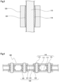
FIG. 2 is an enlarged view illustrating the part encircled with a broken line inFIG. 1 ; -
FIG. 3 is a schematic cross-sectional view illustrating an alternative configuration example of bushing; -
FIG. 4 is a cross-sectional view illustrating part of one configuration example of a chain according to a second embodiment of the present invention; -
FIG. 5 is an enlarged view illustrating the part encircled with a broken line inFIG. 4 ; -
FIG. 6 is a cross-sectional view illustrating part of one configuration example of a chain according to a third embodiment of the present invention; -
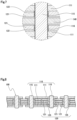
FIG. 7 is an enlarged view illustrating the part encircled with a broken line inFIG. 6 ; -
FIG. 8 is a cross-sectional view illustrating part of one configuration example of a chain according to a fourth embodiment of the present invention; -
FIG. 9 is an enlarged view illustrating the part encircled with a broken line inFIG. 8 ; -
FIG. 10 is a cross-sectional view illustrating part of one configuration example of a chain according to a fifth embodiment of the present invention; and -
FIG. 11 is an enlarged view illustrating the part encircled with a broken line inFIG. 10 . - Below, the chain according to the embodiments of the present invention is described with reference to the drawings.
-
FIG. 1 is a cross-sectional view illustrating part of one configuration example of a chain according to a first embodiment of the present invention. - This
chain 100 is configured as a roller chain and includesouter link plates 111,inner link plates 121,pins 115,bushings 125, androllers 130 as the chain components. - The
chain 100 includes: a plurality ofouter links 110 each made up of a pair of left and rightouter link plates 111 and a pair of front andrear pins 115 coupled thereto; a plurality ofinner links 120 each made up of a pair of left and rightinner link plates 121 disposed between the pair of left and rightouter link plates 111 and a pair of front and rearcylindrical bushings 125 coupled thereto; androllers 130 fitted on thebushings 125. These plurality ofouter links 110 andinner links 120 are alternately and pivotably coupled together along the longitudinal direction of the chain by thepins 115 inserted in thebushings 125. - In the
chain 100 according to this embodiment, thepins 115, andbushings 125, which are mutually sliding chain components sliding against thepins 115, are formed with hardenedsurface layers FIG. 2 containing one of Cr carbide, Ti carbide, V carbide, Nb carbide, Cr nitride, Ti nitride, V nitride, and Nb nitride on their entire sliding surfaces. - These materials, when used as the hardened surface layer, can provide a high surface hardness and reduce wear, compared to
pins 115 made of a material hardened simply by a thermal process. Since thepins 115 as well as thebushings 125 are respectively formed with the hardenedsurface layers surface layers pins 115 andbushings 125 suffer less wear from mutual sliding. Thus elongation of thechain 100 is minimized. - While the
pins 115 in thechain 100 of this embodiment have the hardenedsurface layer 116 covering their entire outer circumferential surface, the hardenedsurface layer 116 may cover at least part of the outer circumferential surface of thepins 115 that slides against the inner circumferential surface of thebushings 125. - The
bushings 125 have the hardenedsurface layer 126 covering their inner circumferential surface, which is the sliding surface that slides against the outer circumferential surface of thepins 115. In an alternative configuration, the hardened surface layer may also be provided to both end faces of thebushings 125 that make contact with inner side faces of theouter link plates 111, and to an outer circumferential surface of thebushings 125 that makes contact with an inner circumferential surface of therollers 130. - The hardened
surface layers - The hardened
surface layer 116 of thepins 115 should preferably have a smaller sliding surface roughness than that of the hardenedsurface layer 126 of thebushings 125. Specifically, the sliding surface roughness Rk of the hardenedsurface layer 116 of thepins 115 should preferably be 0.04 um to 0.30 um, and the sliding surface roughness Rk of the hardenedsurface layer 126 of thebushings 125 should preferably be 0.8 um to 2.0 um. - Abrasive wear and oil film shortage can be effectively retarded by making the sliding surface roughness of the hardened
surface layer 116 of thepins 115 smaller than that of the hardenedsurface layer 126 of thebushings 125. The sliding surface roughness values of the hardenedsurface layers pins 115 and thebushings 125 being set within the respective ranges above also allow any physical contaminants that got in between the outer circumferential surface of thepins 115 and the inner circumferential surface of thebushings 125 to be readily released, and keep the lubricating oil retained more easily on the sliding surface of thebushings 125. This helps improve the wear resistance of thepins 115 and bushings 125 and minimize elongation of thechain 100. - The sliding surface roughness Rk here refers to the effective load roughness as defined by JIS B0671-2:2002. Other surface roughness parameters may be employed, as long as the ranges of Rk values specified above are substantially covered.
- The hardened
surface layer 116 of thepins 115 and the hardenedsurface layer 126 of thebushings 125 should preferably each have a sliding surface hardness (HV) of 1600 or more and 3500 or less. This hardness is higher than that of silicon or alumina, so that abrasive wear on the respective sliding surfaces of thepins 115 andbushings 125 caused by physical contaminants can be reliably prevented even when high-hardness contaminants such as silicon or alumina particles are contained in the lubricating oil. - The
bushings 125 in thechain 100 of this embodiment are cylindrical, with its inner circumferential surface conforming to a cylindrical circumferential surface. Preferably, thebushings 125 should have a concave inner circumferential surface as shown inFIG. 3 . This configuration allows thebushing 125 to keep its sliding surface roughness even after some wear caused by the sliding contact with thepin 115, and therefore any physical contaminants that got in between the outer circumferential surface of thepins 115 and the inner circumferential surface of thebushings 125 can be readily released, and the lubricating oil can be retained more easily on the sliding surface of thebushings 125. The wear resistance of thepins 115 andbushings 125 can thus be further improved. - While the chain described above is configured as a roller chain, the present invention is not limited to roller chains.
- For example, the chain according to the present invention may be configured as a bushing chain as shown in
FIG. 4 andFIG. 5 , which is similar to the roller chain according to the first embodiment but without the rollers on thebushings 125 of theinner links 120. The components inFIG. 4 andFIG. 5 that are the same as those of the roller chain according to the first embodiment are given the same reference numerals for convenience of description. - The
chain 100 according to this embodiment includesouter link plates 111,inner link plates 121, pins 115, andbushings 125. Thepins 115, andbushings 125, which are mutually sliding chain components sliding against thepins 115, are formed with hardened surface layers 116 and 126 containing one of Cr carbide, Ti carbide, V carbide, Nb carbide, Cr nitride, Ti nitride, V nitride, and Nb nitride on their entire sliding surfaces. - While the
pins 115 in the chain of this embodiment have the hardenedsurface layer 116 covering their entire outer circumferential surface, thehardened surface layer 116 may cover at least part of the outer circumferential surface of thepins 115 that slides against the inner circumferential surface of thebushings 125. - The
bushings 125 have the hardenedsurface layer 126 covering their inner circumferential surface, which is the sliding surface that slides against the outer circumferential surface of thepins 115. In an alternative configuration, the hardened surface layer may also be provided to both end faces of thebushings 125 that make contact with inner side faces of theouter link plates 111, and to an outer circumferential surface of thebushings 125 that makes contact with an inner circumferential surface of therollers 130. - The
bushings 125 in thechain 100 of this embodiment should also preferably have a concave inner circumferential surface. -
FIG. 6 is a cross-sectional view illustrating part of one configuration example of a chain according to a third embodiment of the present invention. - This
chain 100 is configured as a silent chain and includesouter link plates 111,middle link plates 140,inner link plates 121, and pins 115 as the chain components. - More specifically, the
chain 100 of this embodiment is made up of a plurality ofouter links 110 that form guide rows, a plurality ofinner links 120 that form non-guide rows, and pins 115 that couple together theouter links 110 andinner links 120 adjacent each other in the longitudinal direction alternately and pivotably along the longitudinal direction of the chain. Theouter links 110 each include a pair of left and rightouter link plates 111 formed with a pair of front and rear pin holes, and amiddle link plate 140 disposed between the pair of left and rightouter link plates 111 and formed with a pair of front and rear pin holes. Theinner links 120 each include a pair of left and rightinner link plates 121 each disposed between theouter link plate 111 and themiddle link plate 140 and formed with a pair of front and rear pin holes. - These plurality of
outer links 110 andinner links 120 are coupled together pivotably by thepins 115 with both ends fixedly pressed into the pin holes of theouter link plates 111, passed through the pin holes of themiddle link plate 140, and loosely fitted in the pin holes of theinner link plates 121. - In the
chain 100 of this embodiment, eachouter link 110 has onemiddle link plate 140 and eachinner link 120 has a pair ofinner link plates 121. Instead, the chain may be configured withouter links 110 having two or moremiddle link plates 140 andinner links 120 having two or more pairs ofinner link plates 121. - In the
chain 100 according to this embodiment, thepins 115, andinner link plates 121, which are mutually sliding chain components sliding against thepins 115, are formed with hardened surface layers 116 and 122 as shown inFIG. 7 containing one of Cr carbide, Ti carbide, V carbide, Nb carbide, Cr nitride, Ti nitride, V nitride, and Nb nitride on their entire sliding surfaces. - While the
pins 115 have the hardenedsurface layer 116 covering their entire outer circumferential surface, thehardened surface layer 116 may cover at least part of the outer circumferential surface of thepins 115 that slides against the inner circumferential surface of the pin holes in theinner link plates 121. - The
inner link plates 121 have the hardenedsurface layer 122 covering the inner circumferential surface of the pin holes, which is the sliding surface that slides against the outer circumferential surface of thepins 115. In an alternative configuration, the hardened surface layer may also be provided to both side faces of theinner link plates 121 that face the inner side faces of theouter link plates 111 and side faces of themiddle link plate 140. - In the case where the chain according to the present invention is configured as a silent chain, it may be configured to include
bushings 125 that are fitted on thepins 115 as shown inFIG. 8 to FIG. 11 , i.e., as a bushed silent chain. -
FIG. 8 is a cross-sectional view illustrating part of one configuration example of a chain according to a fourth embodiment of the present invention. - This
chain 100 is configured as a bushed silent chain and includesouter link plates 111,inner link plates 121, pins 115, andbushings 125 as the chain components. - More specifically, the
chain 100 of this embodiment includes: a plurality ofouter links 110 each made up of a pair of left and rightouter link plates 111 and a pair of front andrear pins 115 coupled thereto; and a plurality ofinner links 120 each made up of a plurality ofinner link plates 121 disposed between the pair of left and rightouter link plates 111 and a pair of front and rearcylindrical bushings 125 coupled thereto. These plurality ofouter links 110 andinner links 120 are alternately and pivotably coupled together along the longitudinal direction of the chain by thepins 115 inserted in thebushings 125. - In the
chain 100 according to this embodiment, thepins 115, andbushings 125, which are mutually sliding chain components sliding against thepins 115, are formed with hardened surface layers 116 and 126 as shown inFIG. 9 containing one of Cr carbide, Ti carbide, V carbide, Nb carbide, Cr nitride, Ti nitride, V nitride, and Nb nitride on their entire sliding surfaces. - While the
pins 115 in thechain 100 of this embodiment have the hardenedsurface layer 116 covering their entire outer circumferential surface, thehardened surface layer 116 may cover at least part of the outer circumferential surface of thepins 115 that slides against the inner circumferential surface of thebushings 125. - The
bushings 125 have the hardenedsurface layer 126 covering the inner circumferential surface, which is the sliding surface that slides against the outer circumferential surface of thepins 115. In an alternative configuration, the hardened surface layer may also be provided to both end faces of thebushings 125 that make contact with inner side faces of theouter link plates 111, and to an outer circumferential surface of thebushings 125. - The
bushings 125 in thechain 100 of this embodiment should also preferably have a concave inner circumferential surface. -
FIG. 10 is a cross-sectional view illustrating part of one configuration example of a chain according to a fifth embodiment of the present invention. - This
chain 100 is configured as a bushed silent chain and includesouter link plates 111,middle link plates 140,inner link plates 121, pins 115, andbushings 125 as the chain components. - More specifically, the
chain 100 of this embodiment is made up of a plurality ofouter links 110 that form guide rows, and a plurality ofinner links 120 that form non-guide rows. - The
outer links 110 each include a pair of left and rightouter link plates 111 formed with a pair of front and rear pin holes, a pair of front andrear pins 115 pressed into the pin holes of theouter link plates 111 and fixed at both ends, and amiddle link plate 140 disposed between the pair of left and rightouter link plates 111 with thepins 115 passed through the pair of front and rear pin holes. - The
inner links 120 each include a plurality ofinner link plates 121 each disposed between theouter link plate 111 and themiddle link plate 140 and formed with a pair of front and rear pin holes, andbushings 125 fixedly pressed into the pin holes in eachinner link plate 121. - These plurality of
outer links 110 andinner links 120 are alternately and pivotably coupled together along the longitudinal direction of the chain by thepins 115 inserted in thebushings 125. - In the
chain 100 according to this embodiment, thepins 115, andbushings 125, which are mutually sliding chain components sliding against thepins 115, are formed with hardened surface layers 116 and 126 as shown inFIG. 11 containing one of Cr carbide, Ti carbide, V carbide, Nb carbide, Cr nitride, Ti nitride, V nitride, and Nb nitride on their entire sliding surfaces. - While the
pins 115 in thechain 100 of this embodiment have the hardenedsurface layer 116 covering their entire outer circumferential surface, the hardened surface layer may cover at least part of the outer circumferential surface of thepins 115 that slides against the inner circumferential surface of thebushings 125. - The
bushings 125 have the hardenedsurface layer 126 covering their inner circumferential surface, which is the sliding surface that slides against the outer circumferential surface of thepins 115. In an alternative configuration, the hardened surface layer may also be provided to both end faces of thebushings 125 that make contact with inner side faces of theouter link plates 111 and one side face of themiddle link plate 140, and to an outer circumferential surface of thebushings 125. - The
bushings 125 in thechain 100 of this embodiment should also preferably have a concave inner circumferential surface. - Below, a wear test carried out to investigate the characteristics of the chain according to the present invention is described.
- A roller chain with the configuration shown in
FIG. 1 and FIG. 2 according to the present invention was prepared for the test (hereinafter referred to as Invention Product 1). The chain has an 8 mm pitch. - The hardened surface layer formed on each of the outer circumferential surface of the pins and the inner circumferential surface of the bushings of the Invention Product 1 was 15 um thick and contained a chromium carbide layer or a vanadium carbide layer. The sliding surface hardness of the hardened surface layer was adjusted to a Vickers hardness number of 2500 HV. The sliding surface roughness Rk on the hardened surface layer of the pins and the sliding surface roughness Rk on the hardened surface layer of the bushings were adjusted to the range of 0.04 um to 0.30 um and 0.8 um to 2.0 um, respectively.
- Roller chains having the same configuration as that of the Invention Product 1 except that the hardened surface layer of the pins and the hardened surface layer of the bushings both have a sliding surface hardness of 1900 HV (hereinafter referred to as Invention Product 2), and except that the hardened surface layer of the pins and the hardened surface layer of the bushings both have a sliding surface hardness of 3200 HV (hereinafter referred to as Invention Product 3), were prepared.
- Further, a roller chain having the same configuration as that of the Invention Product 1 except that the hardened surface layer of the pins has a sliding surface roughness Rk of 0.04 um and the hardened surface layer of the bushings has a sliding surface roughness Rk of 0.73 um was prepared (hereinafter referred to as Comparison Product 1).
- Further, a roller chain having the same configuration as that of the Invention Product 1 except that the hardened surface layer of the pins has a sliding surface roughness Rk of 0.36 um was prepared (hereinafter referred to as Comparison Product 2).
- Further, a roller chain having the same configuration as that of the Invention Product 1 except that the hardened surface layer of the bushings has a sliding surface roughness Rk of 2.4 um was prepared (hereinafter referred to as Comparison Product 3).
- Moreover, a roller chain having the same configuration as that of the Invention Product 1 except that the hardened surface layer is formed only on the outer circumferential surface of the pins and not on the inner circumferential surface of the bushings was prepared (hereinafter referred to as Normal Product).
- A wear test was conducted with the following test conditions on the Invention Products 1 to 3, Comparison Products 1 to 3, and Normal Product, and relative values of the total amount of wear on the pins and bushings in each of the Invention Products 1 to 3 and Comparison Products 1 to 3 were determined relative to the total amount of wear on the pins and bushings in the Normal Product, which is taken as 100%. The results are shown in Table 1 below.
Wear-Induced Elongation Test Conditions - Number of Sprocket Teeth: 18 × 36
- Rotation Speed: 3000 r/min
- Lubricating Oil: Contaminated oil, prepared by adding 11 mass% silicon particles (average size 17 µm) and 9 mass% alumina particles (average size 17 µm) in normal engine oil.
- Oil Amount: 1 L/min
- The results of the chain elongation test conducted on the invention products and the normal product and comparison products for comparison are based only on the outcome of a chain elongation test that was conducted using normal motor test equipment under the above conditions. The above test is a highly reproducible method commonly used in the art and therefore it is assumed that other test methods will produce results with a similar tendency.
[Table 1] Total Amount of Wear (Relative Value) Invention Product 1 53 [%] Invention Product 2 61 [%] Invention Product 3 66 [%] Comparison Product 1 80 [%] Comparison Product 2 71 [%] Comparison Product 3 76 [%] - As is clear from the results shown in Table 1, it was confirmed that the amount of wear could be significantly reduced in Invention Products 1 to 3 compared to Normal Product. An almost 1/2 reduction in the amount of wear was confirmed in Invention Product 1 in particular as compared to the normal product.
- The amount of wear in each of Comparison Products 1 to 3 was smaller than that of the normal product, but larger than that of Invention Products 1 to 3, which confirmed poorer wear resistance of the pins and bushings.
- While embodiments of the present invention have been described in detail, the present invention is not limited to the embodiments described above and may be carried out with various design changes without departing from the scope of the present invention set forth in the claims.
- For example, the roller chain according to the first embodiment, and bushed silent chains according to the fourth and fifth embodiments were described as being configured with the bushings being fixedly pressed into the inner link plates at both ends. As long as the chain is configured such that the inner link plates are arranged at fixed intervals, the bushings need not necessarily be fixedly pressed into the inner link plates.
Claims (6)
- A chain comprising at least a plurality of link plates and a plurality of pins as chain components,
the pins and mutually sliding chain components sliding against the pins being formed with a hardened surface layer containing one of Cr carbide, Ti carbide, V carbide, Nb carbide, Cr nitride, Ti nitride, V nitride, and Nb nitride on part or all of respective sliding surfaces. - The chain according to claim 1, wherein the chain components include bushings fitted on the pins,
the mutually sliding chain components being the bushings. - The chain according to claim 1 or 2, wherein the hardened surface layer of the pins has a smaller sliding surface roughness than the hardened surface layer of the mutually sliding chain components.
- The chain according to claim 3, wherein the hardened surface layer of the pins has a sliding surface roughness Rk of 0.04 um to 0.30 um, and
the hardened surface layer of the mutually sliding chain components has a sliding surface roughness Rk of 0.8 um to 2.0 um. - The chain according to any one of claims 1 to 4, wherein the hardened surface layer of the pins and the hardened surface layer of the mutually sliding chain components each have a sliding surface hardness of 1600 HV or more and 3500 HV or less.
- The chain according to claim 2, wherein the bushings have a concave inner circumferential surface.
Applications Claiming Priority (1)
| Application Number | Priority Date | Filing Date | Title |
|---|---|---|---|
| JP2022037131A JP7801572B2 (en) | 2022-03-10 | 2022-03-10 | chain |
Publications (2)
| Publication Number | Publication Date |
|---|---|
| EP4242488A1 true EP4242488A1 (en) | 2023-09-13 |
| EP4242488B1 EP4242488B1 (en) | 2024-05-29 |
Family
ID=85511122
Family Applications (1)
| Application Number | Title | Priority Date | Filing Date |
|---|---|---|---|
| EP23160482.8A Active EP4242488B1 (en) | 2022-03-10 | 2023-03-07 | Chain |
Country Status (6)
| Country | Link |
|---|---|
| US (1) | US12595838B2 (en) |
| EP (1) | EP4242488B1 (en) |
| JP (1) | JP7801572B2 (en) |
| CN (1) | CN116733907A (en) |
| DK (1) | DK4242488T3 (en) |
| TW (1) | TW202342900A (en) |
Families Citing this family (1)
| Publication number | Priority date | Publication date | Assignee | Title |
|---|---|---|---|---|
| CN114718989A (en) * | 2020-12-22 | 2022-07-08 | 株式会社椿本链条 | chain |
Citations (3)
| Publication number | Priority date | Publication date | Assignee | Title |
|---|---|---|---|---|
| EP1970596A1 (en) * | 2007-03-12 | 2008-09-17 | Honda Motor Co., Ltd. | Chain |
| GB2449152A (en) * | 2007-05-08 | 2008-11-12 | Tsubakimoto Chain Co | Chain where the surface roughness of the pins is smaller than the surface roughness of the bushings |
| JP6920607B2 (en) * | 2015-08-28 | 2021-08-18 | 株式会社椿本チエイン | chain |
Family Cites Families (9)
| Publication number | Priority date | Publication date | Assignee | Title |
|---|---|---|---|---|
| US3831240A (en) * | 1971-04-02 | 1974-08-27 | Caterpillar Tractor Co | Method of installing vented plugs in pin bores |
| JPS61184246A (en) * | 1985-02-06 | 1986-08-16 | Daido Kogyo Co Ltd | Corrosion resistant chain |
| JP2951257B2 (en) * | 1996-02-26 | 1999-09-20 | 株式会社椿本チエイン | Low noise chain with oil groove |
| ITMO20020104A1 (en) * | 2002-04-24 | 2003-10-24 | Pro 2 Srl | ARTICULATED CHAIN |
| US6869244B2 (en) * | 2002-12-17 | 2005-03-22 | Caterpillar Inc | Articulated pin joint for a track chain |
| US20090017950A1 (en) * | 2007-07-12 | 2009-01-15 | Montanari Sandro | Flexibile bicycle chain |
| US20100035714A1 (en) * | 2007-07-12 | 2010-02-11 | Montanari Sandro | Flexible Bicycle Chain |
| WO2009040915A1 (en) | 2007-09-27 | 2009-04-02 | Daido Kogyo Co., Ltd. | Link chain |
| US20180283496A1 (en) * | 2017-03-28 | 2018-10-04 | Tsubakimoto Chain Co. | Chain component and chain |
-
2022
- 2022-03-10 JP JP2022037131A patent/JP7801572B2/en active Active
-
2023
- 2023-02-08 CN CN202310081319.0A patent/CN116733907A/en active Pending
- 2023-02-22 TW TW112106364A patent/TW202342900A/en unknown
- 2023-03-06 US US18/117,965 patent/US12595838B2/en active Active
- 2023-03-07 EP EP23160482.8A patent/EP4242488B1/en active Active
- 2023-03-07 DK DK23160482.8T patent/DK4242488T3/en active
Patent Citations (4)
| Publication number | Priority date | Publication date | Assignee | Title |
|---|---|---|---|---|
| EP1970596A1 (en) * | 2007-03-12 | 2008-09-17 | Honda Motor Co., Ltd. | Chain |
| GB2449152A (en) * | 2007-05-08 | 2008-11-12 | Tsubakimoto Chain Co | Chain where the surface roughness of the pins is smaller than the surface roughness of the bushings |
| JP2008281027A (en) | 2007-05-08 | 2008-11-20 | Tsubakimoto Chain Co | Chain for automobile engine |
| JP6920607B2 (en) * | 2015-08-28 | 2021-08-18 | 株式会社椿本チエイン | chain |
Also Published As
| Publication number | Publication date |
|---|---|
| JP2023132039A (en) | 2023-09-22 |
| US20230287963A1 (en) | 2023-09-14 |
| CN116733907A (en) | 2023-09-12 |
| JP7801572B2 (en) | 2026-01-19 |
| US12595838B2 (en) | 2026-04-07 |
| EP4242488B1 (en) | 2024-05-29 |
| TW202342900A (en) | 2023-11-01 |
| DK4242488T3 (en) | 2024-06-24 |
Similar Documents
| Publication | Publication Date | Title |
|---|---|---|
| JP3199225B2 (en) | Silent chain | |
| KR102203306B1 (en) | Sliding member, chain link, and chain comprising said link | |
| EP1455115B1 (en) | Power transmission chain with ceramic joint components | |
| US6179741B1 (en) | Random engagement roller chain sprocket with cushion rings and root relief for improved noise characteristics | |
| EP1881231B1 (en) | Chain for use in automobile engine | |
| EP1980642B1 (en) | Sliding part | |
| US20080227575A1 (en) | Chain | |
| US20060094551A1 (en) | Silent chain and method of producing same | |
| JP2002130384A (en) | Silent chain of locker pin type | |
| EP4242488B1 (en) | Chain | |
| US20080280716A1 (en) | Chain for use in automobile engine | |
| US6805646B2 (en) | Double-sided meshing type silent chain | |
| US7546725B2 (en) | Silent chain | |
| US20020132690A1 (en) | Silent chain | |
| US20060032207A1 (en) | Process for making a roller chain | |
| EP0982515A1 (en) | Silent chain having links with sheared apertures and vanadium carbide coated pins | |
| US20030087747A1 (en) | Wear-resistant coating and silent chain coated with same | |
| US20090191998A1 (en) | Toothed belt drive for the use with oil | |
| US20080125262A1 (en) | Chain for use in automobile engine | |
| EP1610030B1 (en) | Power transmission chain | |
| JP4456396B2 (en) | Method for forming hard carbide layer, and roller chain and silent chain obtained by this method | |
| CN113574291B (en) | Chain transmission device | |
| EP1907725B1 (en) | Link chain having nitrided bearing face with oxidation coating |
Legal Events
| Date | Code | Title | Description |
|---|---|---|---|
| PUAI | Public reference made under article 153(3) epc to a published international application that has entered the european phase |
Free format text: ORIGINAL CODE: 0009012 |
|
| STAA | Information on the status of an ep patent application or granted ep patent |
Free format text: STATUS: THE APPLICATION HAS BEEN PUBLISHED |
|
| AK | Designated contracting states |
Kind code of ref document: A1 Designated state(s): AL AT BE BG CH CY CZ DE DK EE ES FI FR GB GR HR HU IE IS IT LI LT LU LV MC ME MK MT NL NO PL PT RO RS SE SI SK SM TR |
|
| STAA | Information on the status of an ep patent application or granted ep patent |
Free format text: STATUS: REQUEST FOR EXAMINATION WAS MADE |
|
| 17P | Request for examination filed |
Effective date: 20230925 |
|
| RBV | Designated contracting states (corrected) |
Designated state(s): AL AT BE BG CH CY CZ DE DK EE ES FI FR GB GR HR HU IE IS IT LI LT LU LV MC ME MK MT NL NO PL PT RO RS SE SI SK SM TR |
|
| RIC1 | Information provided on ipc code assigned before grant |
Ipc: F16G 13/06 20060101AFI20231013BHEP |
|
| GRAP | Despatch of communication of intention to grant a patent |
Free format text: ORIGINAL CODE: EPIDOSNIGR1 |
|
| STAA | Information on the status of an ep patent application or granted ep patent |
Free format text: STATUS: GRANT OF PATENT IS INTENDED |
|
| INTG | Intention to grant announced |
Effective date: 20231220 |
|
| GRAS | Grant fee paid |
Free format text: ORIGINAL CODE: EPIDOSNIGR3 |
|
| GRAA | (expected) grant |
Free format text: ORIGINAL CODE: 0009210 |
|
| STAA | Information on the status of an ep patent application or granted ep patent |
Free format text: STATUS: THE PATENT HAS BEEN GRANTED |
|
| AK | Designated contracting states |
Kind code of ref document: B1 Designated state(s): AL AT BE BG CH CY CZ DE DK EE ES FI FR GB GR HR HU IE IS IT LI LT LU LV MC ME MK MT NL NO PL PT RO RS SE SI SK SM TR |
|
| REG | Reference to a national code |
Ref country code: CH Ref legal event code: EP |
|
| REG | Reference to a national code |
Ref country code: IE Ref legal event code: FG4D |
|
| REG | Reference to a national code |
Ref country code: DE Ref legal event code: R096 Ref document number: 602023000111 Country of ref document: DE |
|
| REG | Reference to a national code |
Ref country code: DK Ref legal event code: T3 Effective date: 20240618 |
|
| REG | Reference to a national code |
Ref country code: NL Ref legal event code: FP |
|
| REG | Reference to a national code |
Ref country code: LT Ref legal event code: MG9D |
|
| PG25 | Lapsed in a contracting state [announced via postgrant information from national office to epo] |
Ref country code: IS Free format text: LAPSE BECAUSE OF FAILURE TO SUBMIT A TRANSLATION OF THE DESCRIPTION OR TO PAY THE FEE WITHIN THE PRESCRIBED TIME-LIMIT Effective date: 20240929 |
|
| PG25 | Lapsed in a contracting state [announced via postgrant information from national office to epo] |
Ref country code: BG Free format text: LAPSE BECAUSE OF FAILURE TO SUBMIT A TRANSLATION OF THE DESCRIPTION OR TO PAY THE FEE WITHIN THE PRESCRIBED TIME-LIMIT Effective date: 20240529 |
|
| PG25 | Lapsed in a contracting state [announced via postgrant information from national office to epo] |
Ref country code: HR Free format text: LAPSE BECAUSE OF FAILURE TO SUBMIT A TRANSLATION OF THE DESCRIPTION OR TO PAY THE FEE WITHIN THE PRESCRIBED TIME-LIMIT Effective date: 20240529 Ref country code: FI Free format text: LAPSE BECAUSE OF FAILURE TO SUBMIT A TRANSLATION OF THE DESCRIPTION OR TO PAY THE FEE WITHIN THE PRESCRIBED TIME-LIMIT Effective date: 20240529 |
|
| PG25 | Lapsed in a contracting state [announced via postgrant information from national office to epo] |
Ref country code: GR Free format text: LAPSE BECAUSE OF FAILURE TO SUBMIT A TRANSLATION OF THE DESCRIPTION OR TO PAY THE FEE WITHIN THE PRESCRIBED TIME-LIMIT Effective date: 20240830 |
|
| REG | Reference to a national code |
Ref country code: AT Ref legal event code: MK05 Ref document number: 1690893 Country of ref document: AT Kind code of ref document: T Effective date: 20240529 |
|
| PG25 | Lapsed in a contracting state [announced via postgrant information from national office to epo] |
Ref country code: ES Free format text: LAPSE BECAUSE OF FAILURE TO SUBMIT A TRANSLATION OF THE DESCRIPTION OR TO PAY THE FEE WITHIN THE PRESCRIBED TIME-LIMIT Effective date: 20240529 |
|
| PG25 | Lapsed in a contracting state [announced via postgrant information from national office to epo] |
Ref country code: AT Free format text: LAPSE BECAUSE OF FAILURE TO SUBMIT A TRANSLATION OF THE DESCRIPTION OR TO PAY THE FEE WITHIN THE PRESCRIBED TIME-LIMIT Effective date: 20240529 |
|
| PG25 | Lapsed in a contracting state [announced via postgrant information from national office to epo] |
Ref country code: PL Free format text: LAPSE BECAUSE OF FAILURE TO SUBMIT A TRANSLATION OF THE DESCRIPTION OR TO PAY THE FEE WITHIN THE PRESCRIBED TIME-LIMIT Effective date: 20240529 |
|
| PG25 | Lapsed in a contracting state [announced via postgrant information from national office to epo] |
Ref country code: LV Free format text: LAPSE BECAUSE OF FAILURE TO SUBMIT A TRANSLATION OF THE DESCRIPTION OR TO PAY THE FEE WITHIN THE PRESCRIBED TIME-LIMIT Effective date: 20240529 |
|
| PG25 | Lapsed in a contracting state [announced via postgrant information from national office to epo] |
Ref country code: PL Free format text: LAPSE BECAUSE OF FAILURE TO SUBMIT A TRANSLATION OF THE DESCRIPTION OR TO PAY THE FEE WITHIN THE PRESCRIBED TIME-LIMIT Effective date: 20240529 Ref country code: NO Free format text: LAPSE BECAUSE OF FAILURE TO SUBMIT A TRANSLATION OF THE DESCRIPTION OR TO PAY THE FEE WITHIN THE PRESCRIBED TIME-LIMIT Effective date: 20240829 Ref country code: LV Free format text: LAPSE BECAUSE OF FAILURE TO SUBMIT A TRANSLATION OF THE DESCRIPTION OR TO PAY THE FEE WITHIN THE PRESCRIBED TIME-LIMIT Effective date: 20240529 Ref country code: IS Free format text: LAPSE BECAUSE OF FAILURE TO SUBMIT A TRANSLATION OF THE DESCRIPTION OR TO PAY THE FEE WITHIN THE PRESCRIBED TIME-LIMIT Effective date: 20240929 Ref country code: HR Free format text: LAPSE BECAUSE OF FAILURE TO SUBMIT A TRANSLATION OF THE DESCRIPTION OR TO PAY THE FEE WITHIN THE PRESCRIBED TIME-LIMIT Effective date: 20240529 Ref country code: GR Free format text: LAPSE BECAUSE OF FAILURE TO SUBMIT A TRANSLATION OF THE DESCRIPTION OR TO PAY THE FEE WITHIN THE PRESCRIBED TIME-LIMIT Effective date: 20240830 Ref country code: FI Free format text: LAPSE BECAUSE OF FAILURE TO SUBMIT A TRANSLATION OF THE DESCRIPTION OR TO PAY THE FEE WITHIN THE PRESCRIBED TIME-LIMIT Effective date: 20240529 Ref country code: ES Free format text: LAPSE BECAUSE OF FAILURE TO SUBMIT A TRANSLATION OF THE DESCRIPTION OR TO PAY THE FEE WITHIN THE PRESCRIBED TIME-LIMIT Effective date: 20240529 Ref country code: BG Free format text: LAPSE BECAUSE OF FAILURE TO SUBMIT A TRANSLATION OF THE DESCRIPTION OR TO PAY THE FEE WITHIN THE PRESCRIBED TIME-LIMIT Effective date: 20240529 Ref country code: AT Free format text: LAPSE BECAUSE OF FAILURE TO SUBMIT A TRANSLATION OF THE DESCRIPTION OR TO PAY THE FEE WITHIN THE PRESCRIBED TIME-LIMIT Effective date: 20240529 Ref country code: RS Free format text: LAPSE BECAUSE OF FAILURE TO SUBMIT A TRANSLATION OF THE DESCRIPTION OR TO PAY THE FEE WITHIN THE PRESCRIBED TIME-LIMIT Effective date: 20240829 |
|
| PG25 | Lapsed in a contracting state [announced via postgrant information from national office to epo] |
Ref country code: EE Free format text: LAPSE BECAUSE OF FAILURE TO SUBMIT A TRANSLATION OF THE DESCRIPTION OR TO PAY THE FEE WITHIN THE PRESCRIBED TIME-LIMIT Effective date: 20240529 |
|
| PG25 | Lapsed in a contracting state [announced via postgrant information from national office to epo] |
Ref country code: CZ Free format text: LAPSE BECAUSE OF FAILURE TO SUBMIT A TRANSLATION OF THE DESCRIPTION OR TO PAY THE FEE WITHIN THE PRESCRIBED TIME-LIMIT Effective date: 20240529 |
|
| PG25 | Lapsed in a contracting state [announced via postgrant information from national office to epo] |
Ref country code: SK Free format text: LAPSE BECAUSE OF FAILURE TO SUBMIT A TRANSLATION OF THE DESCRIPTION OR TO PAY THE FEE WITHIN THE PRESCRIBED TIME-LIMIT Effective date: 20240529 Ref country code: RO Free format text: LAPSE BECAUSE OF FAILURE TO SUBMIT A TRANSLATION OF THE DESCRIPTION OR TO PAY THE FEE WITHIN THE PRESCRIBED TIME-LIMIT Effective date: 20240529 |
|
| PG25 | Lapsed in a contracting state [announced via postgrant information from national office to epo] |
Ref country code: SM Free format text: LAPSE BECAUSE OF FAILURE TO SUBMIT A TRANSLATION OF THE DESCRIPTION OR TO PAY THE FEE WITHIN THE PRESCRIBED TIME-LIMIT Effective date: 20240529 |
|
| PG25 | Lapsed in a contracting state [announced via postgrant information from national office to epo] |
Ref country code: SM Free format text: LAPSE BECAUSE OF FAILURE TO SUBMIT A TRANSLATION OF THE DESCRIPTION OR TO PAY THE FEE WITHIN THE PRESCRIBED TIME-LIMIT Effective date: 20240529 Ref country code: SK Free format text: LAPSE BECAUSE OF FAILURE TO SUBMIT A TRANSLATION OF THE DESCRIPTION OR TO PAY THE FEE WITHIN THE PRESCRIBED TIME-LIMIT Effective date: 20240529 Ref country code: RO Free format text: LAPSE BECAUSE OF FAILURE TO SUBMIT A TRANSLATION OF THE DESCRIPTION OR TO PAY THE FEE WITHIN THE PRESCRIBED TIME-LIMIT Effective date: 20240529 Ref country code: EE Free format text: LAPSE BECAUSE OF FAILURE TO SUBMIT A TRANSLATION OF THE DESCRIPTION OR TO PAY THE FEE WITHIN THE PRESCRIBED TIME-LIMIT Effective date: 20240529 Ref country code: CZ Free format text: LAPSE BECAUSE OF FAILURE TO SUBMIT A TRANSLATION OF THE DESCRIPTION OR TO PAY THE FEE WITHIN THE PRESCRIBED TIME-LIMIT Effective date: 20240529 |
|
| PG25 | Lapsed in a contracting state [announced via postgrant information from national office to epo] |
Ref country code: IT Free format text: LAPSE BECAUSE OF FAILURE TO SUBMIT A TRANSLATION OF THE DESCRIPTION OR TO PAY THE FEE WITHIN THE PRESCRIBED TIME-LIMIT Effective date: 20240529 |
|
| REG | Reference to a national code |
Ref country code: DE Ref legal event code: R097 Ref document number: 602023000111 Country of ref document: DE |
|
| PLBE | No opposition filed within time limit |
Free format text: ORIGINAL CODE: 0009261 |
|
| STAA | Information on the status of an ep patent application or granted ep patent |
Free format text: STATUS: NO OPPOSITION FILED WITHIN TIME LIMIT |
|
| PG25 | Lapsed in a contracting state [announced via postgrant information from national office to epo] |
Ref country code: SI Free format text: LAPSE BECAUSE OF FAILURE TO SUBMIT A TRANSLATION OF THE DESCRIPTION OR TO PAY THE FEE WITHIN THE PRESCRIBED TIME-LIMIT Effective date: 20240529 |
|
| 26N | No opposition filed |
Effective date: 20250303 |
|
| PG25 | Lapsed in a contracting state [announced via postgrant information from national office to epo] |
Ref country code: SE Free format text: LAPSE BECAUSE OF FAILURE TO SUBMIT A TRANSLATION OF THE DESCRIPTION OR TO PAY THE FEE WITHIN THE PRESCRIBED TIME-LIMIT Effective date: 20240529 |
|
| PG25 | Lapsed in a contracting state [announced via postgrant information from national office to epo] |
Ref country code: MC Free format text: LAPSE BECAUSE OF FAILURE TO SUBMIT A TRANSLATION OF THE DESCRIPTION OR TO PAY THE FEE WITHIN THE PRESCRIBED TIME-LIMIT Effective date: 20240529 |
|
| PG25 | Lapsed in a contracting state [announced via postgrant information from national office to epo] |
Ref country code: LU Free format text: LAPSE BECAUSE OF NON-PAYMENT OF DUE FEES Effective date: 20250307 |
|
| REG | Reference to a national code |
Ref country code: BE Ref legal event code: MM Effective date: 20250331 |
|
| PG25 | Lapsed in a contracting state [announced via postgrant information from national office to epo] |
Ref country code: FR Free format text: LAPSE BECAUSE OF NON-PAYMENT OF DUE FEES Effective date: 20250331 |
|
| PG25 | Lapsed in a contracting state [announced via postgrant information from national office to epo] |
Ref country code: BE Free format text: LAPSE BECAUSE OF NON-PAYMENT OF DUE FEES Effective date: 20250331 |
|
| PG25 | Lapsed in a contracting state [announced via postgrant information from national office to epo] |
Ref country code: IE Free format text: LAPSE BECAUSE OF NON-PAYMENT OF DUE FEES Effective date: 20250307 |
|
| PGFP | Annual fee paid to national office [announced via postgrant information from national office to epo] |
Ref country code: NL Payment date: 20260213 Year of fee payment: 4 |
|
| PGFP | Annual fee paid to national office [announced via postgrant information from national office to epo] |
Ref country code: DK Payment date: 20260313 Year of fee payment: 4 Ref country code: DE Payment date: 20260128 Year of fee payment: 4 |