EP4242111A1 - Method and apparatus for controlling electrical machines operating with a turbine engine - Google Patents
Method and apparatus for controlling electrical machines operating with a turbine engine Download PDFInfo
- Publication number
- EP4242111A1 EP4242111A1 EP23159522.4A EP23159522A EP4242111A1 EP 4242111 A1 EP4242111 A1 EP 4242111A1 EP 23159522 A EP23159522 A EP 23159522A EP 4242111 A1 EP4242111 A1 EP 4242111A1
- Authority
- EP
- European Patent Office
- Prior art keywords
- electrical machine
- engine
- power
- aircraft
- mode
- Prior art date
- Legal status (The legal status is an assumption and is not a legal conclusion. Google has not performed a legal analysis and makes no representation as to the accuracy of the status listed.)
- Pending
Links
Images



Classifications
-
- B—PERFORMING OPERATIONS; TRANSPORTING
- B64—AIRCRAFT; AVIATION; COSMONAUTICS
- B64D—EQUIPMENT FOR FITTING IN OR TO AIRCRAFT; FLIGHT SUITS; PARACHUTES; ARRANGEMENT OR MOUNTING OF POWER PLANTS OR PROPULSION TRANSMISSIONS IN AIRCRAFT
- B64D31/00—Power plant control systems; Arrangement of power plant control systems in aircraft
- B64D31/02—Initiating means
- B64D31/06—Initiating means actuated automatically
-
- B—PERFORMING OPERATIONS; TRANSPORTING
- B64—AIRCRAFT; AVIATION; COSMONAUTICS
- B64D—EQUIPMENT FOR FITTING IN OR TO AIRCRAFT; FLIGHT SUITS; PARACHUTES; ARRANGEMENT OR MOUNTING OF POWER PLANTS OR PROPULSION TRANSMISSIONS IN AIRCRAFT
- B64D31/00—Power plant control systems; Arrangement of power plant control systems in aircraft
-
- B—PERFORMING OPERATIONS; TRANSPORTING
- B64—AIRCRAFT; AVIATION; COSMONAUTICS
- B64D—EQUIPMENT FOR FITTING IN OR TO AIRCRAFT; FLIGHT SUITS; PARACHUTES; ARRANGEMENT OR MOUNTING OF POWER PLANTS OR PROPULSION TRANSMISSIONS IN AIRCRAFT
- B64D27/00—Arrangement or mounting of power plants in aircraft; Aircraft characterised by the type or position of power plants
- B64D27/02—Aircraft characterised by the type or position of power plants
- B64D27/30—Aircraft characterised by electric power plants
- B64D27/33—Hybrid electric aircraft
-
- B—PERFORMING OPERATIONS; TRANSPORTING
- B64—AIRCRAFT; AVIATION; COSMONAUTICS
- B64D—EQUIPMENT FOR FITTING IN OR TO AIRCRAFT; FLIGHT SUITS; PARACHUTES; ARRANGEMENT OR MOUNTING OF POWER PLANTS OR PROPULSION TRANSMISSIONS IN AIRCRAFT
- B64D31/00—Power plant control systems; Arrangement of power plant control systems in aircraft
- B64D31/16—Power plant control systems; Arrangement of power plant control systems in aircraft for electric power plants
- B64D31/18—Power plant control systems; Arrangement of power plant control systems in aircraft for electric power plants for hybrid-electric power plants
-
- B—PERFORMING OPERATIONS; TRANSPORTING
- B64—AIRCRAFT; AVIATION; COSMONAUTICS
- B64D—EQUIPMENT FOR FITTING IN OR TO AIRCRAFT; FLIGHT SUITS; PARACHUTES; ARRANGEMENT OR MOUNTING OF POWER PLANTS OR PROPULSION TRANSMISSIONS IN AIRCRAFT
- B64D35/00—Transmitting power from power plants to propellers or rotors; Arrangements of transmissions
- B64D35/02—Transmitting power from power plants to propellers or rotors; Arrangements of transmissions specially adapted for specific power plants
- B64D35/021—Transmitting power from power plants to propellers or rotors; Arrangements of transmissions specially adapted for specific power plants for electric power plants
-
- B—PERFORMING OPERATIONS; TRANSPORTING
- B64—AIRCRAFT; AVIATION; COSMONAUTICS
- B64D—EQUIPMENT FOR FITTING IN OR TO AIRCRAFT; FLIGHT SUITS; PARACHUTES; ARRANGEMENT OR MOUNTING OF POWER PLANTS OR PROPULSION TRANSMISSIONS IN AIRCRAFT
- B64D35/00—Transmitting power from power plants to propellers or rotors; Arrangements of transmissions
- B64D35/02—Transmitting power from power plants to propellers or rotors; Arrangements of transmissions specially adapted for specific power plants
- B64D35/021—Transmitting power from power plants to propellers or rotors; Arrangements of transmissions specially adapted for specific power plants for electric power plants
- B64D35/022—Transmitting power from power plants to propellers or rotors; Arrangements of transmissions specially adapted for specific power plants for electric power plants of hybrid-electric type
- B64D35/023—Transmitting power from power plants to propellers or rotors; Arrangements of transmissions specially adapted for specific power plants for electric power plants of hybrid-electric type of series-parallel type
-
- B—PERFORMING OPERATIONS; TRANSPORTING
- B64—AIRCRAFT; AVIATION; COSMONAUTICS
- B64D—EQUIPMENT FOR FITTING IN OR TO AIRCRAFT; FLIGHT SUITS; PARACHUTES; ARRANGEMENT OR MOUNTING OF POWER PLANTS OR PROPULSION TRANSMISSIONS IN AIRCRAFT
- B64D35/00—Transmitting power from power plants to propellers or rotors; Arrangements of transmissions
- B64D35/02—Transmitting power from power plants to propellers or rotors; Arrangements of transmissions specially adapted for specific power plants
- B64D35/021—Transmitting power from power plants to propellers or rotors; Arrangements of transmissions specially adapted for specific power plants for electric power plants
- B64D35/022—Transmitting power from power plants to propellers or rotors; Arrangements of transmissions specially adapted for specific power plants for electric power plants of hybrid-electric type
- B64D35/024—Transmitting power from power plants to propellers or rotors; Arrangements of transmissions specially adapted for specific power plants for electric power plants of hybrid-electric type of series type
-
- F—MECHANICAL ENGINEERING; LIGHTING; HEATING; WEAPONS; BLASTING
- F01—MACHINES OR ENGINES IN GENERAL; ENGINE PLANTS IN GENERAL; STEAM ENGINES
- F01D—NON-POSITIVE DISPLACEMENT MACHINES OR ENGINES, e.g. STEAM TURBINES
- F01D15/00—Adaptations of machines or engines for special use; Combinations of engines with devices driven thereby
- F01D15/10—Adaptations for driving, or combinations with, electric generators
-
- F—MECHANICAL ENGINEERING; LIGHTING; HEATING; WEAPONS; BLASTING
- F02—COMBUSTION ENGINES; HOT-GAS OR COMBUSTION-PRODUCT ENGINE PLANTS
- F02C—GAS-TURBINE PLANTS; AIR INTAKES FOR JET-PROPULSION PLANTS; CONTROLLING FUEL SUPPLY IN AIR-BREATHING JET-PROPULSION PLANTS
- F02C7/00—Features, components parts, details or accessories, not provided for in, or of interest apart form groups F02C1/00 - F02C6/00; Air intakes for jet-propulsion plants
- F02C7/32—Arrangement, mounting, or driving, of auxiliaries
-
- F—MECHANICAL ENGINEERING; LIGHTING; HEATING; WEAPONS; BLASTING
- F02—COMBUSTION ENGINES; HOT-GAS OR COMBUSTION-PRODUCT ENGINE PLANTS
- F02C—GAS-TURBINE PLANTS; AIR INTAKES FOR JET-PROPULSION PLANTS; CONTROLLING FUEL SUPPLY IN AIR-BREATHING JET-PROPULSION PLANTS
- F02C7/00—Features, components parts, details or accessories, not provided for in, or of interest apart form groups F02C1/00 - F02C6/00; Air intakes for jet-propulsion plants
- F02C7/36—Power transmission arrangements between the different shafts of the gas turbine plant, or between the gas-turbine plant and the power user
-
- F—MECHANICAL ENGINEERING; LIGHTING; HEATING; WEAPONS; BLASTING
- F05—INDEXING SCHEMES RELATING TO ENGINES OR PUMPS IN VARIOUS SUBCLASSES OF CLASSES F01-F04
- F05D—INDEXING SCHEME FOR ASPECTS RELATING TO NON-POSITIVE-DISPLACEMENT MACHINES OR ENGINES, GAS-TURBINES OR JET-PROPULSION PLANTS
- F05D2220/00—Application
- F05D2220/70—Application in combination with
- F05D2220/76—Application in combination with an electrical generator
-
- F—MECHANICAL ENGINEERING; LIGHTING; HEATING; WEAPONS; BLASTING
- F05—INDEXING SCHEMES RELATING TO ENGINES OR PUMPS IN VARIOUS SUBCLASSES OF CLASSES F01-F04
- F05D—INDEXING SCHEME FOR ASPECTS RELATING TO NON-POSITIVE-DISPLACEMENT MACHINES OR ENGINES, GAS-TURBINES OR JET-PROPULSION PLANTS
- F05D2240/00—Components
- F05D2240/40—Use of a multiplicity of similar components
-
- F—MECHANICAL ENGINEERING; LIGHTING; HEATING; WEAPONS; BLASTING
- F05—INDEXING SCHEMES RELATING TO ENGINES OR PUMPS IN VARIOUS SUBCLASSES OF CLASSES F01-F04
- F05D—INDEXING SCHEME FOR ASPECTS RELATING TO NON-POSITIVE-DISPLACEMENT MACHINES OR ENGINES, GAS-TURBINES OR JET-PROPULSION PLANTS
- F05D2260/00—Function
- F05D2260/84—Redundancy
-
- F—MECHANICAL ENGINEERING; LIGHTING; HEATING; WEAPONS; BLASTING
- F05—INDEXING SCHEMES RELATING TO ENGINES OR PUMPS IN VARIOUS SUBCLASSES OF CLASSES F01-F04
- F05D—INDEXING SCHEME FOR ASPECTS RELATING TO NON-POSITIVE-DISPLACEMENT MACHINES OR ENGINES, GAS-TURBINES OR JET-PROPULSION PLANTS
- F05D2270/00—Control
- F05D2270/30—Control parameters, e.g. input parameters
- F05D2270/335—Output power or torque
Definitions
- Aircraft engines are typically coupled to electrical machines (e.g., motor generators) that provide power to the engine and/or take power from the engine to operate electrical devices in the aircraft.
- electrical machines e.g., motor generators
- the efficient operation of these devices allows the aircraft to operate properly, for example, by providing adequate thrust at takeoff of the aircraft and also maintaining adequate electrical power for the operation of internal electrical systems of the aircraft at all times.
- Next-generation turbofan and turboprop aircraft engines have a significant increase in required power generation capability.
- the approaches described herein provide electrified propulsion systems with multi-engine and multi-spool (shaft) power extraction as well as the ability to transfer power from one spool to another.
- Such electric architectures may or may not include an additional energy storage device to receive or provide electrical power.
- the approaches presented herein provide a control methodology for managing the interactions between the engine thrust control and the electrical machine control.
- these approaches utilize an array of electric machines applied to various independent main engine spools or shafts to optimize engine cycle performance while meeting aircraft electrical power demands. Since the control methodology considers a multiple array of electrical machines attached to independent engine shafts from an engine system level, electrical power can be extracted from one main shaft (e.g., operate as a generator) and applied as mechanical power to another main shaft (e.g., operating as a motor).
- the approaches provided herein are agnostic to electric architectures that choose to have an integrated battery or other external power source.
- the deterministic torque/power scheduling also allows for a feedforward disturbance rejection integrated with the primary engine control for tighter thrust holding.
- These approaches meet the increasing electric power consumption demands of the engine and the aircraft while minimizing impact to primary control of the engine. Further, these approaches provide deterministic power transfer and power split scheduling for better propulsion system efficiency.
- the approaches provided herein provide improved transient capability and operability by integrating engine and electric machine power management. The present approaches improve time on the wing of the engine due to reducing cycle temperature and improve thrust control due to disturbance rejection logic of electrical power demands.
- the present approaches additionally provide direct-feedback available for thrust control integration, and local supervisor level optimization. These approaches are agnostic to aircraft electric machine (EM) architecture (e.g., battery vs no battery or external energy source or sink).
- EM electric machine
- an approach for operating electrical machine associated with an aircraft engine includes determining a first mode to operate a first electrical machine and a second mode to operate a second electrical machine, the first electrical machine coupled to a first shaft of an engine and the second electrical machine coupled to a second shaft of an engine.
- the first electrical machine is operated according to the first mode and the second electrical machine is operated according to the second mode.
- a power split of operation of the first electrical machine and the second electrical machine is determined.
- the operation of the first electrical machine and the second electrical machine are controlled according to the power split.
- the power split is optimized to protect operating constraints of the engine and the safety of aircraft components while delivering required thrust to the engine.
- the first engine shaft supplies mechanical power to the first electrical machine operating in the first mode and electrical power is supplied to the aircraft and to the second electrical machine on the second shaft of the engine.
- the second mode comprises a torque mode in which the second electrical machine supplies power to the engine.
- determining the power split of operation utilizes a table.
- operating conditions of the aircraft are applied to the table to obtain the power split of operation.
- the power split of operation is determined.
- the first mode and the second mode are selected based on characteristics of the first electrical machine and the second electrical machine.
- the first mode and second mode may be selected on characteristics such as machine size or operating speed.
- the aircraft components comprise aircraft instruments such as environmental systems and communication systems.
- the required thrust is received from a cockpit system operated by a pilot or from an aircraft management system (AMS). For instance, the pilot my operate a lever to indicate the desired thrust.
- AMS aircraft management system
- the first electrical machine and the second electrical machine are operated so as to produce stepwise and gradual changes.
- the amount of torque or electrical power may be increased or decreased gradually rather than according to large steps.
- a system comprises a first electrical machine coupled to a first shaft of an engine of an aircraft; a second electrical machine coupled to a second shaft of the engine of the aircraft; and a controller coupled to the first electrical machine and the second electrical machine.
- the controller is configured to: determine a first mode to operate the first electrical machine and a second mode to operate the second electrical machine, and operate the first electrical machine according to the first mode and the second electrical machine according to the second mode; determine a power split of operation of the first electrical machine and the second electrical machine; and control the operation of the first electrical machine and the second electrical machine according to the power split, the power split being optimized to protect operating constraints of the engine and the safety of aircraft components while delivering required thrust to the engine.
- Approximating language is applied to modify any quantitative representation that could permissibly vary without resulting in a change in the basic function to which it is related. Accordingly, a value modified by a term or terms such as “about”, “approximately”, and “substantially”, are not to be limited to the precise value specified. In at least some instances, the approximating language may correspond to the precision of an instrument for measuring the value, or the precision of the methods or machines for constructing or manufacturing the components and/or systems. For example, the approximating language may refer to being within a 10 percent margin.
- the system 100 includes a controller (e.g., full authority digital engine control (FADEC) controller) 102, an aircraft engine 104, a first electrical machine 106 with a first power converter 108, a second electrical machine 110 with a second power converter 112, an nth electrical machine 114 with an nth power converter 116, a shared electrical bus118, and aircraft (and aircraft systems) 120.
- controller e.g., full authority digital engine control (FADEC) controller
- FADEC full authority digital engine control
- the controller 102 is coupled to the first power converter 108, the second power converter 112 and the nth power converter 116.
- controller refers broadly to any microcontroller, computer, or processor-based device with processor, memory, and programmable input/output peripherals, which is generally designed to govern the operation of other components and devices. It is further understood to include common accompanying accessory devices, including memory, transceivers for communication with other components and devices, etc. These architectural options are well known and understood in the art and require no further description here.
- the controller 102 may be configured (for example, by using corresponding programming stored in a memory as will be well understood by those skilled in the art) to carry out one or more of the steps, actions, and/or functions described herein.
- the controller 102 may include a memory that includes computer instructions that implement any of the functions described herein.
- the aircraft engine 104 includes various components of an aircraft engine.
- the aircraft engine includes shafts a compressor section, a combustion section, and a turbine section.
- Separate mechanical shafts (or spools) 160, 162, and 164 couple to components in these sections.
- the separate mechanical shafts 160, 162, and 164 are also mechanically coupled to the first electrical machine 106, the second electrical machine 110, and the nth electrical machine 114.
- the separate mechanical shafts 160, 162, and 164 supply torque to the aircraft engine 104 when a particular electrical machine operates in torque mode.
- the separate mechanical shafts 160, 162, and 164 supply torque from the aircraft engine 104 to a particular electrical machine when the electrical machine operates in voltage mode.
- the first electrical machine 106, the second electrical machine 110, and the nth electrical machine 114 are motor and/or generator devices. In some aspects of operation these devices operate as motors, that is, the devices operate in a torque mode and provide torque to the aircraft engine 104. In other examples, the devices operate as electric generators and provide electrical power to the shared electrical bus 118.
- the first electrical machine is coupled to a first shaft of an engine and the second electrical machine is coupled to a second shaft of an engine, for example.
- the first power converter 108, the second power converter 112, and nth power converter 116 are configured by the controller 102 to cause their associated electrical machines 106, 110, and 114 operate in different modes and according to different operating parameters.
- the controller 102 instructs the first power converter 108, the second power converter 112, or the nth power converter 116 to operate in voltage mode or torque mode.
- Voltage mode is typically assigned to the electric machine with the greatest capacity for holding electrical bus voltage and supplies electrical energy from the aircraft engine 104 to the shared electrical bus 118.
- Torque mode is typically assigned to the electric machine (and associated shaft) where it is most beneficial for the controller 102 to directly schedule and supplies energy to the aircraft engine 104 from a particular electrical machine.
- the first power converter 108, the second power converter 112, and nth power converter 116 comprise electrical and/or electronic components that operate associated electrical machines 106, 110, and 114 according to different modes of operations. These components may be analog or digital components and may include controllers (e.g., microprocessors). The controller 102 configures (e.g., sets, sends instructions, or otherwise alters) these components so that the electrical machines 106, 110, and 114 operate in the selected mode.
- controllers e.g., microprocessors
- the shared electrical bus 118 comprises wires, buses, cables, or other connections that transmit power from one location to another location.
- the shared electrical bus 118 may also include transmission components such as transistors, resistors, capacitors, switches, repeaters, or other electrical or electronic components that facilitate the transmission of holding of electrical power.
- the aircraft (and aircraft systems) 120 may include the aircraft itself, other engines, and aircraft systems and components such as batteries, de-icing systems, communication systems, lighting systems, environmental systems to mention a few examples that use or consume or hold electrical power.
- the controller 102 configures the first power converter 108 to hold a shared electrical bus voltage on the shared electrical bus 118 using the first electrical machine 106.
- the controller 102 configures the second power converter 112 to generate a controller-commanded torque to the aircraft engine 104 using the second electrical machine 110.
- the controller 102 configures the nth power converter 116 to generate or otherwise create or produce a controller-commanded torque to the aircraft engine 104 using the nth electrical machine 114.
- Connections 146 from the aircraft engine 104 to the first electrical machine 106, the second electrical machine 110, or the nth electrical machine 114 represent power extracted from the corresponding separate mechanical shafts 160, 162, and 164 of the aircraft engine 104 that is used to generate electrical power when the first electrical machine 106, the second electrical machine 110, or the nth electrical machine 114 are operated in voltage mode.
- the first electrical machine 106 is operated in voltage mode.
- Connections 148 from the first electrical machine 106, the second electrical machine 110, or the nth electrical machine 114 to the aircraft engine 104 represent power injected into the corresponding separate mechanical shafts 160, 162, and 164 into the aircraft engine 104 when the first electrical machine 106, the second electrical machine 110, or the nth electrical machine 114 are operated in torque mode.
- Connections 150 between the first electrical machine 106, the second electrical machine 110, or the nth electrical machine 114 and the shared electrical bus represent electrical power delivered to or extracted from the shared electrical bus 118.
- Connection 152 represents the aircraft (and aircraft systems) 120 drawing power from the shared electrical bus 118.
- Connection 154 represents the aircraft (and aircraft systems) 120 providing power to the shared electrical bus 118 (which may couple to a battery or another engine).
- Connection 156 the thrust delivered by the aircraft engine 104 to the aircraft (and aircraft systems) 120.
- the controller 102 determines a first mode (e.g., voltage mode) to operate the first electrical machine 106 and a second mode (e.g., torque mode) to operate the second electrical machine 110.
- the first electrical machine 106 is operated according to the first mode and the second electrical machine 110 is operated according to the second mode using the first power converter 108 and the second power converter 112, respectively.
- a power split of operation of the first electrical machine 106 and the second electrical machine 110 is determined.
- the operation of the first electrical machine 106 and the second electrical machine 110 are controlled by the first power converter 108 and the second power converter 112 as instructed by the controller 102 according to the power split.
- the power split is optimized by the controller 102 to protect operating constraints of the engine and the safety of aircraft components while delivering required thrust to the engine.
- the power split specifies the total power to be maintained at the shared electrical bus 118 and how much is to be supplied or drawn by each of the electrical machines 106 and 110.
- the power split dynamically changes over time. For instance, if one electrical machine draws more power from the shared electrical bus 118 to supply this power to the engine during takeoff, the other electrical machine compensates by providing more electrical power to the shared electrical bus 118 so that the amount of power at the shared electrical bus 118 stays constant or substantially constant.
- the controller 102 issues appropriate commands as needed to the first electrical machine 106 and the second electrical machine 110 to effect these operations. These commands may include the mode that an electrical machine is to operate but also amounts of torque or electrical energy that are needed.
- the power converters/electrical machines may be operated in different modes.
- one power converter/electrical machine is a leader and the other is a follower.
- the first power converter 108 is operated in torque mode (as a leader).
- the second power converter 112 is operated in voltage mode (as a follower).
- Constraints e.g., constraints related to an electrical machine or the aircraft engine 104, etc.
- the second power converter is a follower power converter and regulates a bus voltage on the shared electrical bus 118 as alternating current (AC) load varies on the shared electrical bus 118.
- the AC load may vary, in examples, based upon the number and type of aircraft systems being powered.
- both the first power converter 108 and the second power converter 112 operate in voltage mode.
- both the first power converter 108 and the second power converter 112 operate in torque mode.
- a battery and/or AC supply may be used to supply power to the shared electrical bus 118.
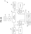
- FIG. 2A one example of a system 250 for controlling electrical devices in a turbine engine is described. It will be appreciated that this system shows an aircraft with two engines.
- the system includes a cockpit 252, an aircraft management system (AMS) 254, a global supervisor 258, a first controller (e.g., a FADEC controller) 256, a second controller (e.g., a FADEC controller) 260, a first engine 262, a first power converter 264, a first electrical machine 266, a second power converter 268, a second electrical machine 270, a second engine 272, a third power converter 274, a third electrical machine 276, a fourth power converter 278, a fourth electrical machine 280, a shared electrical bus 282, energy sources or sinks 284, and aircraft systems 286.
- AMS aircraft management system
- a global supervisor 258 e.g., a first controller (e.g., a FADEC controller) 256
- a second controller e.g., a FADEC controller
- the first controller e.g., a FADEC controller
- the second controller e.g., a FADEC controller
- the first controller is coupled to the first engine 262 to control the engine cycle of the first engine 262.
- the second controller e.g., a FADEC controller
- the second controller is coupled to the second engine 272 to control the engine cycle of the second engine 272.
- the cockpit 252 is where the pilot and other aircraft personnel are located and actuate levers, buttons, or other controls to operate the aircraft. These controls are coupled to the AMS 254, which may include computers or electronic devices that accept controls and pass these to the global supervisor 258.
- the global supervisor may be a controller and operates to determine, for example, how much thrust the first engine 262 will provide as compared to the second engine 272.
- the operation and functionality of the first controller (e.g., a FADEC controller) 256, the second controller (e.g., a FADEC controller) 260, the first engine 262, the first power converter 264, the first electrical machine 266, the second power converter 268, the second electrical machine 270, the second engine 272, the third power converter 274, the third electrical machine 276, the fourth power converter 278, and the fourth electrical machine 280 are the same as similarly-named elements with respect to FIG. 1 and will not be repeated here.
- the first electrical machine 266, the second electrical machine 270, the third electrical machine 276, and the fourth electrical machine 280 couple to the shared electrical bus 282 which is similar to the shared electrical bus described with respect to FIG. 1 .
- the shared electrical bus 282 couples to energy sources or sinks 284 and aircraft systems 286.
- Energy sources or sinks 284 may include batteries or other generators.
- Aircraft systems 286 may include internal aircraft systems that require electrical power such a lighting systems, air conditioning systems, or communication systems to mention a few examples.
- the total system thrust and electrical load levels are set by the aircraft.
- the pilot in the cockpit 252 pushes a lever to indicate a thrust desired.
- the thrust may be set automatically.
- the AMS 254 converts this into electronic commands, which are sent to the global supervisor 258.
- step 204 electric and thrust commands are allocated to each propulsion system by the global supervisor.
- the global supervisor determines how much of the power is to be provided by each of the first engine 262 and the second engine 272.
- the ideal or preferred split between the shafts is determined by the first controller (e.g., a FADEC controller) 256 for the first engine 262 and by the second controller (e.g., a FADEC controller) 260 for the second engine 272.
- the first controller e.g., a FADEC controller
- the second controller e.g., a FADEC controller
- individual electrical machines are set to torque mode or voltage mode by the first controller (e.g., a FADEC controller) 256 and the second controller (e.g., a FADEC controller) 260.
- first controller e.g., a FADEC controller
- second controller e.g., a FADEC controller
- the first controller (e.g., a FADEC controller) 256 and the second controller (e.g., a FADEC controller) 260 determine torque set points for their respective electrical machines (the first electrical machine 266, the second electrical machine 270, the third electrical machine 276, and the fourth electrical machine 280) if the electrical machine is being operated in torque mode.
- the power converters are configured to operate the electrical machines for torque control from the ideal power split and their operation is potentially limited by engine and/or electric machine constraints.
- the electrical machine converts the torque commands to electrical current commands and extracts power from the first engine 262 or second engine 272 and/or injects power into the first engine 262 or second engine 272.
- the conversion may involve converting a torque command from a digital format to an analog (e.g., electrical current) format.
- the electrical current may be used to actuate portions of the electrical machine to supply torque to the first engine 262 or the second engine 272.
- the electrical machine For electrical machines operating in voltage mode, the electrical machine generates the current to preserve the voltage on the shared electrical bus 282.
- electrical machines operating in voltage mode may supply power to the aircraft systems 286 via the shared electrical bus 282.
- Electrical machines operating in voltage mode may supply current to batteries (energy sources or sinks 284).
- the thrust and power required are delivered to the aircraft and sensors provide feedback to the first controller (e.g., a FADEC controller) 256 and the second controller (e.g., a FADEC controller) 260.
- the feedback can be used by the first controller (e.g., a FADEC controller) 256 and the second controller (e.g., a FADEC controller) 260 to fine-tune operations.
- a first mode to operate a first electrical machine and a second mode to operate a second electrical machine are determined, for example, by a controller such as a FADEC controller.
- the first electrical machine is coupled to a first shaft of an engine and the second electrical machine coupled to a first shaft of an engine.
- Voltage mode is typically assigned to the electric machine with the greatest capacity for holding electrical bus voltage. This assignment could mean the electrical machine is sized larger than other motor-generator systems. This could also mean that the selected electrical machine is able to perform faster and/or at a more rapid rate.
- Torque mode is typically assigned to the electric electrical machine (and associated shaft) where it is most beneficial for the engine controller to directly schedule. This assignment could be used to achieve the above steady-state and transient power split. This assignment can be used to satisfy constraints, both from the electric machines and from the engine. In aspects, torque mode is deterministic meaning that all possible values of the torque mode setpoint are bound within a predetermined operating space or range.
- a first engine shaft supplies mechanical power to the first electrical machine operating in a first or torque mode.
- Electrical power is supplied to the aircraft and to the second electrical machine on the second shaft of the engine in a second or voltage mode.
- this is not encompassing of the operation of the torque mode.
- the electrical machine operating in torque mode could, at sometimes also generate power, instead of consuming power.
- an electrical machine operating in voltage mode could be consuming power as opposed to generating power, if another electrical machine operating in torque mode is generating power.
- the first electrical machine is operated according to the first mode and the second electrical machine is operated according to the second mode.
- a power split of operation of the first electrical machine and the second electrical machine is determined.
- the power split is set according to desired steady-state power split (shaft power extraction) and is first set based on optimal efficiency of the engine.
- the exact power split may be obtained using at table look up as a function of operating condition such as aircraft altitude, Mach (speed), or temperature.
- the power split can also be selected using an embedded model (e.g., mathematical or machine learning model) that is capable of estimating turbomachinery efficiency. Splitting power extraction/injection between shafts allows for migration along component maps.
- the transient power split is set based on desired improved transient performance (e.g., faster acceleration/deceleration) or improved operability margin. This power split may be set using a table look-up scheduled as a function of throttle plus the operating condition.
- the operation of the first electrical machine and the second electrical machine is controlled according to the power split.
- the power split is optimized to protect operating constraints of the engine and the safety of aircraft components while delivering required thrust to the engine.
- FIG. 4 and FIG. 5 two graphs describing illustrative embodiments of the invention are described. These graphs show how the two electrical machines are operated.
- FIG. 4 shows a line 402 representing the thrust needed from an electrical machine, and a line labeled 416 indicates the total amount of power needed or requested by the aircraft.
- Time 1 (indicated by the lead line labelled 404) is the time at which a steady state power is provided to the aircraft before the thrust is requested (e.g., by the pilot).
- Time 2 is the time at which thrust is requested (for example, by a pilot) for an amount of thrust so that the aircraft can take off.
- a controller e.g., a FADEC controller
- Constraints on the engine e.g., operational constraints related to temperature or pressure) limit the amount of torque that can actually be applied to the engine(s).
- Rate limits e.g., rate limiting torque
- maximum electric machine torque e.g., being a function of speed
- other engine operability limits e.g., electric machine drivetrain mechanical constraints (e.g., maximum gearbox torque or power output), or leader-follower constraint (e.g., a leader electrical machine demand respects constraints of a follower electrical machine).
- leader-follower constraint e.g., a leader electrical machine demand respects constraints of a follower electrical machine.
- a power split specifying torque amounts to be created is determined using torque mode for some electrical machines and voltage mode electrical machines.
- an amount of torque is supplied by the torque mode electrical machines (within limits set by operating constraints) while the voltage mode electrical machines maintain the shared electrical bus voltage at a constant or substantially constant value.
- Time 3 (indicated by the lead line labelled 408) is the time when the requested thrust is being supplied to the aircraft engine(s).
- Time 4 (indicated by the lead line labelled 410) is a point in time when a new constant power is being provided to the aircraft and the aircraft has taken off.
- FIG. 5 shows the power split between the two electrical machines showing power (extracted or inserted) on the y-axis and time on the x-axis.
- the top line 412 shows power associated with a first electrical machine and a bottom line 414 shows power associated with a second electrical machine.
- a line 416 indicates the total power provided to the aircraft.
- Time 1 (indicated by the lead line labelled 404) power is being drawn from the engine by the first electrical machine and the second electrical machine.
- the second electrical machine supplies less power until at time 406 when it crosses the x-axis so that power in the form of torque is being supplied to the engine. It can be seen that the first electrical machine supplies more electricity to the power bus so that the overall power stays the same.
- the second electrical machine supplies torque to the engine from time 406 (the time when thrust is requested for example by a pilot requesting thrust so that the aircraft is taking off) until time 418 until the maximum power 430 from this torque is achieved.
- the first electrical machine continues to supply power to the power bus until this maximum power 432 is reached.
- the maximum powers are being supplied (to the electrical bus for the first electrical machine) and torque to the eying (for the second electrical machine).
- Lines 434 and 436 are ideal maximum powers but have been lowered because of operating constraints of the engine.
- the second electrical machine is operated to supply less torque because the engine needs less torque. Similarly, the first electrical machine supplies less power to the power bus.
- Time 410 is a point in time when a new constant power is provided to the aircraft.
- the aircraft is taken off and requires no additional thrust. It can be seen that the first electrical machine is supplying more power at time 4 that time 1 after the process has been completed.
- the electrical machine operates between an electrical power state 602, a mechanical power state 604, and a speed state 606.
- the electrical machine may operate to maintain a bus voltage, provide power to the engine, or control to a specific speed.
- electrical power is provided to aircraft systems.
- mechanical power state 604 torque is provided to the shaft of the engine to provide additional power to the engine.
- speed state 606 the operation of the electrical machine is controlled so that the engine operates at a specific speed. It can be seen that the approaches described elsewhere herein will cause a particular electrical machine to operate according to these states.
- at takeoff the aircraft may enter the mechanical power state 604 and this may transition to the electrical power state 602 to provide power to aircraft systems and to the speed state 606 to maintain a speed after takeoff.
- the approaches provided herein are agnostic to electric architectures that choose to have an integrated battery or other external power source. These approaches meet the increasing electric power consumption demands of the engine and the aircraft while minimizing impact to primary control of the engine. Further, these approaches provide deterministic power transfer and power split scheduling for better propulsion system efficiency.
- the approaches provided herein provide improved transient capability and operability by integrating engine and electric machine power management. The present approaches improve time on the wing of the engine due to reducing cycle temperature and improve thrust control due to disturbance rejection logic of electrical power demands.
- controllers may implement the various functionality described herein.
- a controller can include but is not limited to a processor, a memory, and one or more input and/or output (I/O) device interface(s) that are communicatively coupled via a local interface.
- the local interface can include, for example but not limited to, one or more buses and/or other wired or wireless connections.
- the processor may be a hardware device for executing software, particularly software stored in a memory.
- the processor can be a custom made or commercially available processor, a central processing unit (CPU), an auxiliary processor among several processors associated with the computing device, a semiconductorbased microprocessor (in the form of a microchip or chip set) or generally any device for executing software instructions.
- CPU central processing unit
- auxiliary processor among several processors associated with the computing device
- semiconductorbased microprocessor in the form of a microchip or chip set
- the memory devices described herein can include any one or combination of volatile memory elements (e.g., random access memory (RAM), such as dynamic RAM (DRAM), static RAM (SRAM), synchronous dynamic RAM (SDRAM), video RAM (VRAM), and so forth) and/or nonvolatile memory elements (e.g., read only memory (ROM), hard drive, tape, CD-ROM, and so forth).
- volatile memory elements e.g., random access memory (RAM), such as dynamic RAM (DRAM), static RAM (SRAM), synchronous dynamic RAM (SDRAM), video RAM (VRAM), and so forth
- nonvolatile memory elements e.g., read only memory (ROM), hard drive, tape, CD-ROM, and so forth
- ROM read only memory
- the memory can also have a distributed architecture, where various components are situated remotely from one another, but can be accessed by the processor.
- the controllers may implement the functions described herein in any combination of hardware and software (e.g., with the software being executed by a controller).
- the software may be stored in any memory device and may include one or more separate programs, each of which includes an ordered listing of executable instructions for implementing the functions described herein. When constructed as a source program, the program is translated via a compiler, assembler, interpreter, or the like, which may or may not be included within the memory.
- any of the approaches described herein can be implemented at least in part as computer instructions stored on a computer media (e.g., a computer memory as described above) and these instructions can be executed on a controller such as a microprocessor.
- a controller such as a microprocessor.
- these approaches can be implemented as any combination of electronic hardware and/or software.
- a system comprising: a first electrical machine coupled to a first shaft of an engine of an aircraft; a second electrical machine coupled to a second shaft of the engine of the aircraft; a controller coupled to the first electrical machine and the second electrical machine, the controller configured to: determine a first mode to operate the first electrical machine and a second mode to operate the second electrical machine, and operate the first electrical machine according to the first mode and the second electrical machine according to the second mode; determine a power split of operation of the first electrical machine and the second electrical machine; control an operation of the first electrical machine and the second electrical machine according to the power split of operation, the power split of operation being managed to protect operating constraints of the engine while meeting electrical power demands of the aircraft, while also maintaining desired engine thrust to the aircraft.
- the second mode comprises a torque mode in which the second electrical machine supplies mechanical power to the second shaft of the engine.
- the second mode comprises a torque mode in which the second electrical machine supplies power to the engine.
- first mode and the second mode are selected based on characteristics of the first electrical machine and the second electrical machine.
- a method (e.g. of operating electrical machine associated with an aircraft engine), the method comprising: determining a first mode to operate a first electrical machine and a second mode to operate a second electrical machine, the first electrical machine coupled to a first shaft of an engine of an aircraft and the second electrical machine coupled to a second shaft of the engine of the aircraft; operating the first electrical machine according to the first mode and the second electrical machine according to the second mode; determining a power split of operation of the first electrical machine and the second electrical machine; controlling an operation of the first electrical machine and the second electrical machine according to the power split of operation, the power split of operation being managed to protect operating constraints of the engine while meeting electrical power demands of the aircraft, while maintaining desired engine thrust to the aircraft.
- the second mode comprises a torque mode in which the second electrical machine supplies mechanical power to the second shaft of the engine.
- the second mode comprises a torque mode in which the second electrical machine supplies power to the engine.
- first mode and the second mode are selected based on characteristics of the first electrical machine and the second electrical machine.
- a non-transitory, machine-accessible storage medium having computer instructions and wherein the instructions are configured, when executed by a controller, to cause the controller to: determine a first mode to operate a first electrical machine and a second mode to operate a second electrical machine, the first electrical machine coupled to a first shaft of an engine of an aircraft and the second electrical machine coupled to a second shaft of the engine of the aircraft; operate the first electrical machine according to the first mode and the second electrical machine according to the second mode; determine a power split of operation of the first electrical machine and the second electrical machine; control an operation of the first electrical machine and the second electrical machine according to the power split of operation, the power split of operation being managed to protect operating constraints of the engine while meeting electrical power demands of the aircraft, while maintaining desired engine thrust to the aircraft.
- the second mode comprises a torque mode in which the second electrical machine supplies power to the engine.
Landscapes
- Engineering & Computer Science (AREA)
- Mechanical Engineering (AREA)
- Aviation & Aerospace Engineering (AREA)
- Chemical & Material Sciences (AREA)
- Combustion & Propulsion (AREA)
- General Engineering & Computer Science (AREA)
- Control Of Electric Motors In General (AREA)
- Control Of Multiple Motors (AREA)
Abstract
Description
- These teachings relate generally to turbine engines and more particularly to controlling the operation of components associated with turbine engines.
- Aircraft engines are typically coupled to electrical machines (e.g., motor generators) that provide power to the engine and/or take power from the engine to operate electrical devices in the aircraft. The efficient operation of these devices allows the aircraft to operate properly, for example, by providing adequate thrust at takeoff of the aircraft and also maintaining adequate electrical power for the operation of internal electrical systems of the aircraft at all times.
- Various needs are at least partially met through provision of the method and apparatus for managing the operation of electrical machines in a turbine engine described in the following detailed description, particularly when studied in conjunction with the drawings. A full and enabling disclosure of the aspects of the present description, including the best mode thereof, directed to one of ordinary skill in the art, is set forth in the specification, which refers to the appended figures, in which:
-
FIG. 1 comprises a diagram as configured in accordance with various embodiments of these teachings; -
FIG. 2A comprises a diagram as configured in accordance with various embodiments of these teachings; -
FIG. 2B comprises a flowchart as configured in accordance with various embodiments of these teachings; -
FIG. 3 comprises a flowchart as configured in accordance with various embodiments of these teachings; -
FIG. 4 comprises a diagram as configured in accordance with various embodiments of these teachings; -
FIG. 5 comprises a diagram as configured in accordance with various embodiments of these teachings; -
FIG. 6 comprises a diagram as configured in accordance with various embodiments of these teachings. - Elements in the figures are illustrated for simplicity and clarity and have not necessarily been drawn to scale. For example, the dimensions and/or relative positioning of some of the elements in the figures may be exaggerated relative to other elements to help to improve understanding of various embodiments of the present teachings. Also, common but well-understood elements that are useful or necessary in a commercially feasible embodiment are often not depicted in order to facilitate a less obstructed view of these various embodiments of the present teachings. Certain actions and/or steps may be described or depicted in a particular order of occurrence while those skilled in the art will understand that such specificity with respect to sequence is not actually required.
- Next-generation turbofan and turboprop aircraft engines have a significant increase in required power generation capability. The approaches described herein provide electrified propulsion systems with multi-engine and multi-spool (shaft) power extraction as well as the ability to transfer power from one spool to another. Such electric architectures may or may not include an additional energy storage device to receive or provide electrical power.
- The approaches presented herein provide a control methodology for managing the interactions between the engine thrust control and the electrical machine control. In certain aspects, these approaches utilize an array of electric machines applied to various independent main engine spools or shafts to optimize engine cycle performance while meeting aircraft electrical power demands. Since the control methodology considers a multiple array of electrical machines attached to independent engine shafts from an engine system level, electrical power can be extracted from one main shaft (e.g., operate as a generator) and applied as mechanical power to another main shaft (e.g., operating as a motor). Thus, the approaches provided herein are agnostic to electric architectures that choose to have an integrated battery or other external power source.
- Advantageously, the deterministic torque/power scheduling also allows for a feedforward disturbance rejection integrated with the primary engine control for tighter thrust holding. These approaches meet the increasing electric power consumption demands of the engine and the aircraft while minimizing impact to primary control of the engine. Further, these approaches provide deterministic power transfer and power split scheduling for better propulsion system efficiency. The approaches provided herein provide improved transient capability and operability by integrating engine and electric machine power management. The present approaches improve time on the wing of the engine due to reducing cycle temperature and improve thrust control due to disturbance rejection logic of electrical power demands.
- The present approaches additionally provide direct-feedback available for thrust control integration, and local supervisor level optimization. These approaches are agnostic to aircraft electric machine (EM) architecture (e.g., battery vs no battery or external energy source or sink).
- In many of these embodiments, an approach for operating electrical machine associated with an aircraft engine includes determining a first mode to operate a first electrical machine and a second mode to operate a second electrical machine, the first electrical machine coupled to a first shaft of an engine and the second electrical machine coupled to a second shaft of an engine. The first electrical machine is operated according to the first mode and the second electrical machine is operated according to the second mode. A power split of operation of the first electrical machine and the second electrical machine is determined. The operation of the first electrical machine and the second electrical machine are controlled according to the power split. The power split is optimized to protect operating constraints of the engine and the safety of aircraft components while delivering required thrust to the engine.
- In aspects, the first engine shaft supplies mechanical power to the first electrical machine operating in the first mode and electrical power is supplied to the aircraft and to the second electrical machine on the second shaft of the engine. In other aspects, the second mode comprises a torque mode in which the second electrical machine supplies power to the engine. In other examples, determining the power split of operation utilizes a table.
- In other examples, operating conditions of the aircraft are applied to the table to obtain the power split of operation. In still other examples, the power split of operation is determined.
- In still other aspects, the first mode and the second mode are selected based on characteristics of the first electrical machine and the second electrical machine. For example, the first mode and second mode may be selected on characteristics such as machine size or operating speed.
- In other examples, the aircraft components comprise aircraft instruments such as environmental systems and communication systems.
- In some other examples, the required thrust is received from a cockpit system operated by a pilot or from an aircraft management system (AMS). For instance, the pilot my operate a lever to indicate the desired thrust.
- In yet other examples, the first electrical machine and the second electrical machine are operated so as to produce stepwise and gradual changes. For example, the amount of torque or electrical power may be increased or decreased gradually rather than according to large steps.
- In others of these embodiments, a system comprises a first electrical machine coupled to a first shaft of an engine of an aircraft; a second electrical machine coupled to a second shaft of the engine of the aircraft; and a controller coupled to the first electrical machine and the second electrical machine. The controller is configured to: determine a first mode to operate the first electrical machine and a second mode to operate the second electrical machine, and operate the first electrical machine according to the first mode and the second electrical machine according to the second mode; determine a power split of operation of the first electrical machine and the second electrical machine; and control the operation of the first electrical machine and the second electrical machine according to the power split, the power split being optimized to protect operating constraints of the engine and the safety of aircraft components while delivering required thrust to the engine.
- The terms and expressions used herein have the ordinary technical meaning as is accorded to such terms and expressions by persons skilled in the technical field as set forth above except where different specific meanings have otherwise been set forth herein. The word "or" when used herein shall be interpreted as having a disjunctive construction rather than a conjunctive construction unless otherwise specifically indicated. The terms "coupled," "fixed," "attached to," and the like refer to both direct coupling, fixing, or attaching, as well as indirect coupling, fixing, or attaching through one or more intermediate components or features, unless otherwise specified herein.
- The singular forms "a", "an", and "the" include plural references unless the context clearly dictates otherwise.
- Approximating language, as used herein throughout the specification and claims, is applied to modify any quantitative representation that could permissibly vary without resulting in a change in the basic function to which it is related. Accordingly, a value modified by a term or terms such as "about", "approximately", and "substantially", are not to be limited to the precise value specified. In at least some instances, the approximating language may correspond to the precision of an instrument for measuring the value, or the precision of the methods or machines for constructing or manufacturing the components and/or systems. For example, the approximating language may refer to being within a 10 percent margin.
- The foregoing and other benefits may become clearer upon making a thorough review and study of the following detailed description.
- Referring now to
FIG. 1 , one example of asystem 100 for controlling electrical devices in a turbine engine is described. Thesystem 100 includes a controller (e.g., full authority digital engine control (FADEC) controller) 102, anaircraft engine 104, a firstelectrical machine 106 with afirst power converter 108, a secondelectrical machine 110 with asecond power converter 112, an nthelectrical machine 114 with annth power converter 116, a shared electrical bus118, and aircraft (and aircraft systems) 120. "N" is an integer numbers and, in many of the examples described herein, N=2. - The
controller 102 is coupled to thefirst power converter 108, thesecond power converter 112 and thenth power converter 116. It will be appreciated that, as used herein, the term "controller" refers broadly to any microcontroller, computer, or processor-based device with processor, memory, and programmable input/output peripherals, which is generally designed to govern the operation of other components and devices. It is further understood to include common accompanying accessory devices, including memory, transceivers for communication with other components and devices, etc. These architectural options are well known and understood in the art and require no further description here. Thecontroller 102 may be configured (for example, by using corresponding programming stored in a memory as will be well understood by those skilled in the art) to carry out one or more of the steps, actions, and/or functions described herein. Thecontroller 102 may include a memory that includes computer instructions that implement any of the functions described herein. - The
aircraft engine 104 includes various components of an aircraft engine. For example, the aircraft engine includes shafts a compressor section, a combustion section, and a turbine section. Separate mechanical shafts (or spools) 160, 162, and 164 couple to components in these sections. The separatemechanical shafts electrical machine 106, the secondelectrical machine 110, and the nthelectrical machine 114. The separatemechanical shafts aircraft engine 104 when a particular electrical machine operates in torque mode. The separatemechanical shafts aircraft engine 104 to a particular electrical machine when the electrical machine operates in voltage mode. - The first
electrical machine 106, the secondelectrical machine 110, and the nthelectrical machine 114 are motor and/or generator devices. In some aspects of operation these devices operate as motors, that is, the devices operate in a torque mode and provide torque to theaircraft engine 104. In other examples, the devices operate as electric generators and provide electrical power to the sharedelectrical bus 118. The first electrical machine is coupled to a first shaft of an engine and the second electrical machine is coupled to a second shaft of an engine, for example. - The
first power converter 108, thesecond power converter 112, andnth power converter 116 are configured by thecontroller 102 to cause their associatedelectrical machines controller 102 instructs thefirst power converter 108, thesecond power converter 112, or thenth power converter 116 to operate in voltage mode or torque mode. Voltage mode is typically assigned to the electric machine with the greatest capacity for holding electrical bus voltage and supplies electrical energy from theaircraft engine 104 to the sharedelectrical bus 118. Torque mode is typically assigned to the electric machine (and associated shaft) where it is most beneficial for thecontroller 102 to directly schedule and supplies energy to theaircraft engine 104 from a particular electrical machine. - The
first power converter 108, thesecond power converter 112, andnth power converter 116 comprise electrical and/or electronic components that operate associatedelectrical machines controller 102 configures (e.g., sets, sends instructions, or otherwise alters) these components so that theelectrical machines - The shared
electrical bus 118 comprises wires, buses, cables, or other connections that transmit power from one location to another location. The sharedelectrical bus 118 may also include transmission components such as transistors, resistors, capacitors, switches, repeaters, or other electrical or electronic components that facilitate the transmission of holding of electrical power. - The aircraft (and aircraft systems) 120 may include the aircraft itself, other engines, and aircraft systems and components such as batteries, de-icing systems, communication systems, lighting systems, environmental systems to mention a few examples that use or consume or hold electrical power.
- In one example of the operation of the system of
FIG. 1 , atstep 140, thecontroller 102 configures thefirst power converter 108 to hold a shared electrical bus voltage on the sharedelectrical bus 118 using the firstelectrical machine 106. Atstep 142, thecontroller 102 configures thesecond power converter 112 to generate a controller-commanded torque to theaircraft engine 104 using the secondelectrical machine 110. At step 144, thecontroller 102 configures thenth power converter 116 to generate or otherwise create or produce a controller-commanded torque to theaircraft engine 104 using the nthelectrical machine 114. -
Connections 146 from theaircraft engine 104 to the firstelectrical machine 106, the secondelectrical machine 110, or the nthelectrical machine 114 represent power extracted from the corresponding separatemechanical shafts aircraft engine 104 that is used to generate electrical power when the firstelectrical machine 106, the secondelectrical machine 110, or the nthelectrical machine 114 are operated in voltage mode. In this specific example, the firstelectrical machine 106 is operated in voltage mode. -
Connections 148 from the firstelectrical machine 106, the secondelectrical machine 110, or the nthelectrical machine 114 to theaircraft engine 104 represent power injected into the corresponding separatemechanical shafts aircraft engine 104 when the firstelectrical machine 106, the secondelectrical machine 110, or the nthelectrical machine 114 are operated in torque mode. In this specific example, the secondelectrical machine 110 and the nthelectrical machine 114 are operated in torque mode and N=3. -
Connections 150 between the firstelectrical machine 106, the secondelectrical machine 110, or the nthelectrical machine 114 and the shared electrical bus represent electrical power delivered to or extracted from the sharedelectrical bus 118.Connection 152 represents the aircraft (and aircraft systems) 120 drawing power from the sharedelectrical bus 118.Connection 154 represents the aircraft (and aircraft systems) 120 providing power to the shared electrical bus 118 (which may couple to a battery or another engine).Connection 156 the thrust delivered by theaircraft engine 104 to the aircraft (and aircraft systems) 120. - In another example of the operation of
FIG. 1 and assuming only two electrical machines (N=2), thecontroller 102 determines a first mode (e.g., voltage mode) to operate the firstelectrical machine 106 and a second mode (e.g., torque mode) to operate the secondelectrical machine 110. The firstelectrical machine 106 is operated according to the first mode and the secondelectrical machine 110 is operated according to the second mode using thefirst power converter 108 and thesecond power converter 112, respectively. A power split of operation of the firstelectrical machine 106 and the secondelectrical machine 110 is determined. The operation of the firstelectrical machine 106 and the secondelectrical machine 110 are controlled by thefirst power converter 108 and thesecond power converter 112 as instructed by thecontroller 102 according to the power split. The power split is optimized by thecontroller 102 to protect operating constraints of the engine and the safety of aircraft components while delivering required thrust to the engine. - The power split specifies the total power to be maintained at the shared
electrical bus 118 and how much is to be supplied or drawn by each of theelectrical machines electrical bus 118 to supply this power to the engine during takeoff, the other electrical machine compensates by providing more electrical power to the sharedelectrical bus 118 so that the amount of power at the sharedelectrical bus 118 stays constant or substantially constant. Thecontroller 102 issues appropriate commands as needed to the firstelectrical machine 106 and the secondelectrical machine 110 to effect these operations. These commands may include the mode that an electrical machine is to operate but also amounts of torque or electrical energy that are needed. - It will be appreciated that the power converters/electrical machines may be operated in different modes. In a first example, one power converter/electrical machine is a leader and the other is a follower. To take one example, the
first power converter 108 is operated in torque mode (as a leader). Thesecond power converter 112 is operated in voltage mode (as a follower). Constraints (e.g., constraints related to an electrical machine or theaircraft engine 104, etc.) are mapped to the firstelectrical machine 106 via commands generated by thecontroller 102, and the firstelectrical machine 106 becomes the leader in producing torque. The second power converter is a follower power converter and regulates a bus voltage on the sharedelectrical bus 118 as alternating current (AC) load varies on the sharedelectrical bus 118. The AC load may vary, in examples, based upon the number and type of aircraft systems being powered. - In another example, both the
first power converter 108 and thesecond power converter 112 operate in voltage mode. - In still another example, both the
first power converter 108 and thesecond power converter 112 operate in torque mode. A battery and/or AC supply may be used to supply power to the sharedelectrical bus 118. - Referring to
FIG. 2A , one example of asystem 250 for controlling electrical devices in a turbine engine is described. It will be appreciated that this system shows an aircraft with two engines. The system includes acockpit 252, an aircraft management system (AMS) 254, aglobal supervisor 258, a first controller (e.g., a FADEC controller) 256, a second controller (e.g., a FADEC controller) 260, afirst engine 262, afirst power converter 264, a firstelectrical machine 266, asecond power converter 268, a secondelectrical machine 270, asecond engine 272, athird power converter 274, a thirdelectrical machine 276, afourth power converter 278, a fourthelectrical machine 280, a sharedelectrical bus 282, energy sources or sinks 284, andaircraft systems 286. The first controller (e.g., a FADEC controller) 256 is coupled to thefirst engine 262 to control the engine cycle of thefirst engine 262. The second controller (e.g., a FADEC controller) 260 is coupled to thesecond engine 272 to control the engine cycle of thesecond engine 272. - The
cockpit 252 is where the pilot and other aircraft personnel are located and actuate levers, buttons, or other controls to operate the aircraft. These controls are coupled to theAMS 254, which may include computers or electronic devices that accept controls and pass these to theglobal supervisor 258. The global supervisor may be a controller and operates to determine, for example, how much thrust thefirst engine 262 will provide as compared to thesecond engine 272. The operation and functionality of the first controller (e.g., a FADEC controller) 256, the second controller (e.g., a FADEC controller) 260, thefirst engine 262, thefirst power converter 264, the firstelectrical machine 266, thesecond power converter 268, the secondelectrical machine 270, thesecond engine 272, thethird power converter 274, the thirdelectrical machine 276, thefourth power converter 278, and the fourthelectrical machine 280 are the same as similarly-named elements with respect toFIG. 1 and will not be repeated here. The firstelectrical machine 266, the secondelectrical machine 270, the thirdelectrical machine 276, and the fourthelectrical machine 280 couple to the sharedelectrical bus 282 which is similar to the shared electrical bus described with respect toFIG. 1 . The sharedelectrical bus 282 couples to energy sources or sinks 284 andaircraft systems 286. Energy sources or sinks 284 may include batteries or other generators.Aircraft systems 286 may include internal aircraft systems that require electrical power such a lighting systems, air conditioning systems, or communication systems to mention a few examples. - Referring now
FIG. 2B , atstep 202 the total system thrust and electrical load levels are set by the aircraft. For example, the pilot in thecockpit 252 pushes a lever to indicate a thrust desired. In other examples, the thrust may be set automatically. TheAMS 254 converts this into electronic commands, which are sent to theglobal supervisor 258. - At
step 204, electric and thrust commands are allocated to each propulsion system by the global supervisor. The global supervisor determines how much of the power is to be provided by each of thefirst engine 262 and thesecond engine 272. - At
step 206, the ideal or preferred split between the shafts is determined by the first controller (e.g., a FADEC controller) 256 for thefirst engine 262 and by the second controller (e.g., a FADEC controller) 260 for thesecond engine 272. - At
step 208, individual electrical machines (the firstelectrical machine 266, the secondelectrical machine 270, the thirdelectrical machine 276, and the fourth electrical machine 280) are set to torque mode or voltage mode by the first controller (e.g., a FADEC controller) 256 and the second controller (e.g., a FADEC controller) 260. - At
step 210, the first controller (e.g., a FADEC controller) 256 and the second controller (e.g., a FADEC controller) 260 determine torque set points for their respective electrical machines (the firstelectrical machine 266, the secondelectrical machine 270, the thirdelectrical machine 276, and the fourth electrical machine 280) if the electrical machine is being operated in torque mode. The power converters are configured to operate the electrical machines for torque control from the ideal power split and their operation is potentially limited by engine and/or electric machine constraints. - At
step 212, for electrical machines operating in torque mode, the electrical machine converts the torque commands to electrical current commands and extracts power from thefirst engine 262 orsecond engine 272 and/or injects power into thefirst engine 262 orsecond engine 272. For example, the conversion may involve converting a torque command from a digital format to an analog (e.g., electrical current) format. The electrical current may be used to actuate portions of the electrical machine to supply torque to thefirst engine 262 or thesecond engine 272. - At
step 214, for electrical machines operating in voltage mode, the electrical machine generates the current to preserve the voltage on the sharedelectrical bus 282. For example, electrical machines operating in voltage mode may supply power to theaircraft systems 286 via the sharedelectrical bus 282. Electrical machines operating in voltage mode may supply current to batteries (energy sources or sinks 284). - At
step 216, the thrust and power required are delivered to the aircraft and sensors provide feedback to the first controller (e.g., a FADEC controller) 256 and the second controller (e.g., a FADEC controller) 260. In aspects, the feedback can be used by the first controller (e.g., a FADEC controller) 256 and the second controller (e.g., a FADEC controller) 260 to fine-tune operations. - Referring now to
FIG. 3 , one example of a system for operating electrical machines is described. Atstep 302, a first mode to operate a first electrical machine and a second mode to operate a second electrical machine are determined, for example, by a controller such as a FADEC controller. The first electrical machine is coupled to a first shaft of an engine and the second electrical machine coupled to a first shaft of an engine. - Voltage mode is typically assigned to the electric machine with the greatest capacity for holding electrical bus voltage. This assignment could mean the electrical machine is sized larger than other motor-generator systems. This could also mean that the selected electrical machine is able to perform faster and/or at a more rapid rate.
- Torque mode is typically assigned to the electric electrical machine (and associated shaft) where it is most beneficial for the engine controller to directly schedule. This assignment could be used to achieve the above steady-state and transient power split. This assignment can be used to satisfy constraints, both from the electric machines and from the engine. In aspects, torque mode is deterministic meaning that all possible values of the torque mode setpoint are bound within a predetermined operating space or range.
- In examples, a first engine shaft supplies mechanical power to the first electrical machine operating in a first or torque mode. Electrical power is supplied to the aircraft and to the second electrical machine on the second shaft of the engine in a second or voltage mode. However, this is not encompassing of the operation of the torque mode. For instance, the electrical machine operating in torque mode could, at sometimes also generate power, instead of consuming power. Also, an electrical machine operating in voltage mode could be consuming power as opposed to generating power, if another electrical machine operating in torque mode is generating power.
- At
step 304, the first electrical machine is operated according to the first mode and the second electrical machine is operated according to the second mode. - At
step 306, a power split of operation of the first electrical machine and the second electrical machine is determined. The aspects, the power split is set according to desired steady-state power split (shaft power extraction) and is first set based on optimal efficiency of the engine. The exact power split may be obtained using at table look up as a function of operating condition such as aircraft altitude, Mach (speed), or temperature. The power split can also be selected using an embedded model (e.g., mathematical or machine learning model) that is capable of estimating turbomachinery efficiency. Splitting power extraction/injection between shafts allows for migration along component maps. In aspects, the transient power split is set based on desired improved transient performance (e.g., faster acceleration/deceleration) or improved operability margin. This power split may be set using a table look-up scheduled as a function of throttle plus the operating condition. - At
step 308, the operation of the first electrical machine and the second electrical machine is controlled according to the power split. The power split is optimized to protect operating constraints of the engine and the safety of aircraft components while delivering required thrust to the engine. - Referring now to
FIG. 4 andFIG. 5 , two graphs describing illustrative embodiments of the invention are described. These graphs show how the two electrical machines are operated. -
FIG. 4 shows aline 402 representing the thrust needed from an electrical machine, and a line labeled 416 indicates the total amount of power needed or requested by the aircraft. - Time 1 (indicated by the lead line labelled 404) is the time at which a steady state power is provided to the aircraft before the thrust is requested (e.g., by the pilot).
- Time 2 (indicated by the lead line labelled 406) is the time at which thrust is requested (for example, by a pilot) for an amount of thrust so that the aircraft can take off. To increase the acceleration capacity, a controller (e.g., a FADEC controller) commands torque injection into a designated engine shaft using electrical machines configured to operate in torque mode and letting voltage mode-configured electrical machines maintain a shared bus voltage (which supplies power to other aircraft systems. Constraints on the engine (e.g., operational constraints related to temperature or pressure) limit the amount of torque that can actually be applied to the engine(s). Other limits include rate limits (e.g., rate limiting torque), maximum electric machine torque (e.g., being a function of speed), other engine operability limits, electric machine drivetrain mechanical constraints (e.g., maximum gearbox torque or power output), or leader-follower constraint (e.g., a leader electrical machine demand respects constraints of a follower electrical machine). Other examples are possible.
- A power split specifying torque amounts to be created is determined using torque mode for some electrical machines and voltage mode electrical machines. In other words, an amount of torque is supplied by the torque mode electrical machines (within limits set by operating constraints) while the voltage mode electrical machines maintain the shared electrical bus voltage at a constant or substantially constant value.
- Time 3 (indicated by the lead line labelled 408) is the time when the requested thrust is being supplied to the aircraft engine(s).
- Time 4 (indicated by the lead line labelled 410) is a point in time when a new constant power is being provided to the aircraft and the aircraft has taken off.
-
FIG. 5 shows the power split between the two electrical machines showing power (extracted or inserted) on the y-axis and time on the x-axis. - The
top line 412 shows power associated with a first electrical machine and abottom line 414 shows power associated with a second electrical machine. Aline 416 indicates the total power provided to the aircraft. - At Time 1 (indicated by the lead line labelled 404) power is being drawn from the engine by the first electrical machine and the second electrical machine. At time (indicated by the line labeled 418) the second electrical machine supplies less power until at
time 406 when it crosses the x-axis so that power in the form of torque is being supplied to the engine. It can be seen that the first electrical machine supplies more electricity to the power bus so that the overall power stays the same. - The second electrical machine supplies torque to the engine from time 406 (the time when thrust is requested for example by a pilot requesting thrust so that the aircraft is taking off) until
time 418 until themaximum power 430 from this torque is achieved. Similarly, the first electrical machine continues to supply power to the power bus until thismaximum power 432 is reached. Attime 408, the maximum powers are being supplied (to the electrical bus for the first electrical machine) and torque to the eying (for the second electrical machine). -
Lines - At
time 420, the second electrical machine is operated to supply less torque because the engine needs less torque. Similarly, the first electrical machine supplies less power to the power bus. -
Time 410 is a point in time when a new constant power is provided to the aircraft. The aircraft is taken off and requires no additional thrust. It can be seen that the first electrical machine is supplying more power at time 4 thattime 1 after the process has been completed. - Referring now to
FIG. 6 , a state machine of an electrical machine is described. In this example, the electrical machine operates between anelectrical power state 602, amechanical power state 604, and aspeed state 606. The electrical machine may operate to maintain a bus voltage, provide power to the engine, or control to a specific speed. In theelectrical power state 602, electrical power is provided to aircraft systems. In themechanical power state 604, torque is provided to the shaft of the engine to provide additional power to the engine. In thespeed state 606, the operation of the electrical machine is controlled so that the engine operates at a specific speed. It can be seen that the approaches described elsewhere herein will cause a particular electrical machine to operate according to these states. In one example, at takeoff the aircraft may enter themechanical power state 604 and this may transition to theelectrical power state 602 to provide power to aircraft systems and to thespeed state 606 to maintain a speed after takeoff. - Advantageously, the approaches provided herein are agnostic to electric architectures that choose to have an integrated battery or other external power source. These approaches meet the increasing electric power consumption demands of the engine and the aircraft while minimizing impact to primary control of the engine. Further, these approaches provide deterministic power transfer and power split scheduling for better propulsion system efficiency. The approaches provided herein provide improved transient capability and operability by integrating engine and electric machine power management. The present approaches improve time on the wing of the engine due to reducing cycle temperature and improve thrust control due to disturbance rejection logic of electrical power demands.
- It should be understood that the controllers (e.g., the controller 102) provided herein may implement the various functionality described herein. In terms of hardware architecture, such a controller can include but is not limited to a processor, a memory, and one or more input and/or output (I/O) device interface(s) that are communicatively coupled via a local interface. The local interface can include, for example but not limited to, one or more buses and/or other wired or wireless connections. The processor may be a hardware device for executing software, particularly software stored in a memory. The processor can be a custom made or commercially available processor, a central processing unit (CPU), an auxiliary processor among several processors associated with the computing device, a semiconductorbased microprocessor (in the form of a microchip or chip set) or generally any device for executing software instructions.
- The memory devices described herein can include any one or combination of volatile memory elements (e.g., random access memory (RAM), such as dynamic RAM (DRAM), static RAM (SRAM), synchronous dynamic RAM (SDRAM), video RAM (VRAM), and so forth) and/or nonvolatile memory elements (e.g., read only memory (ROM), hard drive, tape, CD-ROM, and so forth). Moreover, the memory may incorporate electronic, magnetic, optical, and/or other types of storage media. The memory can also have a distributed architecture, where various components are situated remotely from one another, but can be accessed by the processor.
- The controllers may implement the functions described herein in any combination of hardware and software (e.g., with the software being executed by a controller). The software may be stored in any memory device and may include one or more separate programs, each of which includes an ordered listing of executable instructions for implementing the functions described herein. When constructed as a source program, the program is translated via a compiler, assembler, interpreter, or the like, which may or may not be included within the memory.
- It will be appreciated that any of the approaches described herein can be implemented at least in part as computer instructions stored on a computer media (e.g., a computer memory as described above) and these instructions can be executed on a controller such as a microprocessor. However, as mentioned, these approaches can be implemented as any combination of electronic hardware and/or software.
- Further aspects of the invention are provided by the subject matter of the following clauses:
A system, the system comprising: a first electrical machine coupled to a first shaft of an engine of an aircraft; a second electrical machine coupled to a second shaft of the engine of the aircraft; a controller coupled to the first electrical machine and the second electrical machine, the controller configured to: determine a first mode to operate the first electrical machine and a second mode to operate the second electrical machine, and operate the first electrical machine according to the first mode and the second electrical machine according to the second mode; determine a power split of operation of the first electrical machine and the second electrical machine; control an operation of the first electrical machine and the second electrical machine according to the power split of operation, the power split of operation being managed to protect operating constraints of the engine while meeting electrical power demands of the aircraft, while also maintaining desired engine thrust to the aircraft. - The system of any preceding clause, wherein the first engine shaft supplies mechanical power to the first electrical machine operating in the first mode and electrical power is supplied to the aircraft and to the second electrical machine on the second shaft of the engine.
- The system of any preceding clause, wherein the second mode comprises a torque mode in which the second electrical machine supplies mechanical power to the second shaft of the engine.
- The system of any preceding clause, wherein the second mode comprises a torque mode in which the second electrical machine supplies power to the engine.
- The system of any preceding clause, wherein the power split of operation is determined according to a table.
- The system of any preceding clause, wherein operating conditions of the aircraft are applied to the table to obtain the power split of operation.
- The system of any preceding clause, wherein the power split of operation is determined by a model.
- The system of any preceding clause, wherein the first mode and the second mode are selected based on characteristics of the first electrical machine and the second electrical machine.
- The system of any preceding clause, wherein the aircraft components comprise aircraft instruments.
- The system of any of the preceding cause, wherein the first electrical machine or the second electrical machine provide electrical power to aircraft instruments.
- The system of any preceding clause, wherein the aircraft instruments comprise environmental systems and communication systems.
- The system of any preceding clause, wherein the desired engine thrust is received from a cockpit system operated by a pilot.
- A method (e.g. of operating electrical machine associated with an aircraft engine), the method comprising: determining a first mode to operate a first electrical machine and a second mode to operate a second electrical machine, the first electrical machine coupled to a first shaft of an engine of an aircraft and the second electrical machine coupled to a second shaft of the engine of the aircraft; operating the first electrical machine according to the first mode and the second electrical machine according to the second mode; determining a power split of operation of the first electrical machine and the second electrical machine; controlling an operation of the first electrical machine and the second electrical machine according to the power split of operation, the power split of operation being managed to protect operating constraints of the engine while meeting electrical power demands of the aircraft, while maintaining desired engine thrust to the aircraft.
- The method of any preceding clause, wherein the first engine shaft supplies mechanical power to the first electrical machine operating in the first mode and electrical power is supplied to the aircraft and to the second electrical machine on the second shaft of the engine.
- The method of any preceding clause, wherein the second mode comprises a torque mode in which the second electrical machine supplies mechanical power to the second shaft of the engine.
- The method of any preceding clause, wherein the second mode comprises a torque mode in which the second electrical machine supplies power to the engine.
- The method of any preceding clause, wherein determining the power split of operation utilizes a table.
- The method of any preceding clause, wherein operating conditions of the aircraft are applied to the table to obtain the power split of operation.
- The method of any preceding clause, wherein determining the power split of operation utilizes a model.
- The method of any preceding clause, wherein the first mode and the second mode are selected based on characteristics of the first electrical machine and the second electrical machine.
- The method of any preceding clause, wherein the first electrical machine or the second electrical machine provide electrical power to aircraft instruments.
- The method of any of preceding clause, wherein the aircraft components comprise aircraft instruments of the aircraft.
- The method of any of preceding clause wherein the aircraft instruments comprise environmental systems and communication systems.
- The method of any preceding clause, further comprising receiving the desired engine thrust from a cockpit system operated by a pilot.
- A non-transitory, machine-accessible storage medium having computer instructions and wherein the instructions are configured, when executed by a controller, to cause the controller to: determine a first mode to operate a first electrical machine and a second mode to operate a second electrical machine, the first electrical machine coupled to a first shaft of an engine of an aircraft and the second electrical machine coupled to a second shaft of the engine of the aircraft; operate the first electrical machine according to the first mode and the second electrical machine according to the second mode; determine a power split of operation of the first electrical machine and the second electrical machine; control an operation of the first electrical machine and the second electrical machine according to the power split of operation, the power split of operation being managed to protect operating constraints of the engine while meeting electrical power demands of the aircraft, while maintaining desired engine thrust to the aircraft.
- The non-transitory, machine-accessible storage medium of any preceding clause, wherein the first engine shaft supplies mechanical power to the first electrical machine operating in the first mode and electrical power is supplied to the aircraft and to the second electrical machine on the second shaft of the engine.
- The non-transitory, machine-accessible storage medium of any preceding clause, wherein the second mode comprises a torque mode in which the second electrical machine supplies power to the engine.
- The non-transitory, machine-accessible storage medium of any preceding clause, wherein determining the power split of operation utilizes a table.
- The non-transitory, machine-accessible storage medium of any preceding clause, wherein operating conditions of the aircraft are applied to the table to obtain the power split of operation.
- The non-transitory, machine-accessible storage medium of any preceding clause, wherein determining the power split of operation utilizes a model.
- The non-transitory, machine-accessible storage medium of any preceding clause, wherein the first mode and the second mode are selected based on characteristics of the first electrical machine and the second electrical machine.
- The non-transitory, machine-accessible storage medium of any preceding clause, wherein the first electrical machine or the second electrical machine provide electrical power to aircraft instruments.
- The non-transitory, machine-accessible storage medium of any of the preceding clause, wherein the aircraft components comprise aircraft instruments of the aircraft.
- The non-transitory, machine-accessible storage medium of any preceding clause, wherein the instructions are further configured, when executed by the controller, to cause the controller to receive the desired engine thrust from a cockpit system operated by a pilot.
- Those skilled in the art will recognize that a wide variety of modifications, alterations, and combinations can be made with respect to the above-described embodiments without departing from the scope of the invention, and that such modifications, alterations, and combinations are to be viewed as being within the ambit of the inventive concept.
Claims (15)
- A system, the system comprising:a first electrical machine (106) coupled to a first shaft (160) of an engine (104) of an aircraft;a second electrical machine (110) coupled to a second shaft (162) of the engine (104) of the aircraft;a controller coupled to the first electrical machine (106) and the second electrical machine (110), the controller (102) configured to:- determine a first mode to operate the first electrical machine (106) and a second mode to operate the second electrical machine (110), and operate the first electrical machine (106) according to the first mode and the second electrical machine (110) according to the second mode;- determine a power split of operation of the first electrical machine (106) and the second electrical machine (110);- control an operation of the first electrical machine (106) and the second electrical machine (110) according to the power split of operation, the power split of operation being managed to protect operating constraints of the engine (104) while meeting electrical power demands of the aircraft, while also maintaining desired engine thrust to the aircraft.
- The system of claim 1, wherein the first shaft (160) of the engine (104) supplies mechanical power to the first electrical machine (106) operating in the first mode and electrical power is supplied to the aircraft and to the second electrical machine (110) on the second shaft (162) of the engine (104).
- The system of any preceding claim, wherein the second mode comprises a torque mode in which the second electrical machine (110) supplies mechanical power to the second shaft (162) of the engine (104).
- The system of any preceding claim, wherein the power split of operation is determined by a model.
- The system of any preceding claim, wherein the first mode and the second mode are selected based on characteristics of the first electrical machine (106) and the second electrical machine (110).
- The system of any preceding claim, wherein the first electrical machine (106) or the second electrical machine provide (110) electrical power to aircraft instruments.
- The system of claim 6 wherein the aircraft instruments comprise environmental systems and communication systems.
- The system of any preceding claim, wherein the desired engine thrust is received from a cockpit system operated by a pilot.
- A method, the method comprising:determining a first mode to operate a first electrical machine (106) and a second mode to operate a second electrical machine (110), the first electrical machine coupled to a first shaft (160) of an engine (104) of an aircraft and the second electrical machine (110) coupled to a second shaft (162) of the engine (104) of the aircraft;operating the first electrical machine (106) according to the first mode and the second electrical machine (110) according to the second mode;
determining a power split of operation of the first electrical machine (106) and the second electrical machine (110);controlling an operation of the first electrical machine (106) and the second electrical machine (110) according to the power split of operation, the power split of operation being managed to protect operating constraints of the engine (104) while meeting electrical power demands of the aircraft, while maintaining desired engine thrust to the aircraft. - The method of claim 9, wherein the first shaft (160) of the engine (104) supplies mechanical power to the first electrical machine (106) operating in the first mode and electrical power is supplied to the aircraft and to the second electrical machine (110) on the second shaft (162) of the engine (104).
- The method of claim 9, wherein the second mode comprises a torque mode in which the second electrical machine (110) supplies mechanical power to the second shaft (162) of the engine (104).
- The method of claim 9 or 10, wherein the first mode and the second mode are selected based on characteristics of the first electrical machine (106) and the second electrical machine (110).
- The method of any of claims 9 to 12, wherein the first electrical machine(106) or the second electrical machine (110) provide electrical power to aircraft instruments.
- The method of claim 13 wherein the aircraft instruments comprise environmental systems and communication systems.
- The method of any of claims 9 to 14, further comprising receiving the desired engine thrust from a cockpit system operated by a pilot.
Applications Claiming Priority (1)
| Application Number | Priority Date | Filing Date | Title |
|---|---|---|---|
| US17/687,832 US12459659B2 (en) | 2022-03-07 | 2022-03-07 | Method and apparatus for controlling electrical machines operating with a turbine engine |
Publications (1)
| Publication Number | Publication Date |
|---|---|
| EP4242111A1 true EP4242111A1 (en) | 2023-09-13 |
Family
ID=85415469
Family Applications (1)
| Application Number | Title | Priority Date | Filing Date |
|---|---|---|---|
| EP23159522.4A Pending EP4242111A1 (en) | 2022-03-07 | 2023-03-01 | Method and apparatus for controlling electrical machines operating with a turbine engine |
Country Status (3)
| Country | Link |
|---|---|
| US (1) | US12459659B2 (en) |
| EP (1) | EP4242111A1 (en) |
| CN (1) | CN116714770A (en) |
Families Citing this family (4)
| Publication number | Priority date | Publication date | Assignee | Title |
|---|---|---|---|---|
| US12031479B2 (en) * | 2020-08-31 | 2024-07-09 | General Electric Company | Hybrid electric propulsion system load share |
| US12006880B2 (en) | 2022-09-12 | 2024-06-11 | General Electric Company | High bandwidth control of turbofan/turboprop thrust response using embedded electric machines |
| KR20260035831A (en) * | 2023-07-10 | 2026-03-13 | 아처 에비에이션 인크. | System and method for flight control of an aircraft |
| US12459660B1 (en) * | 2024-11-15 | 2025-11-04 | Rolls-Royce Corporation | Limited slip torque-limiter coupling |
Citations (5)
| Publication number | Priority date | Publication date | Assignee | Title |
|---|---|---|---|---|
| US20060225431A1 (en) * | 2005-04-08 | 2006-10-12 | United Technologies Corporation | Electrically coupled supercharger for a gas turbine engine |
| US20170335710A1 (en) * | 2016-05-18 | 2017-11-23 | Rolls-Royce North American Technologies, Inc. | Control of low pressure generator for gas turbine engine |
| US10583931B2 (en) * | 2013-12-30 | 2020-03-10 | Rolls-Royce North American Technologies, Inc. | System and method for coordinated control of a power system |
| US20200392906A1 (en) * | 2019-06-12 | 2020-12-17 | Rolls-Royce Plc | Deceleration of a gas turbine |
| US20220063824A1 (en) * | 2020-08-31 | 2022-03-03 | General Electric Company | Hybrid electric propulsion system load share |
Family Cites Families (106)
| Publication number | Priority date | Publication date | Assignee | Title |
|---|---|---|---|---|
| US4425614A (en) | 1969-12-09 | 1984-01-10 | Adaptronics, Inc. | Self-organizing control system |
| US3686485A (en) | 1970-11-03 | 1972-08-22 | Barber Colman Co | Thrust controller for propulsion systems with commonly driven, controllable pitch propellers |
| US3750782A (en) | 1971-10-08 | 1973-08-07 | Ford Motor Co | High speed overrunning clutch |
| EP0839285B1 (en) | 1994-12-14 | 2001-07-18 | United Technologies Corporation | Compressor stall and surge control using airflow asymmetry measruement |
| US6059522A (en) | 1996-04-17 | 2000-05-09 | United Technologies Corporation | Compressor stall diagnostics and avoidance |
| US7011498B2 (en) | 1998-04-03 | 2006-03-14 | Athena Technologies, Inc. | Optimization method for power generation systems |
| US6010303A (en) | 1998-08-05 | 2000-01-04 | United Technologies Corporation | Apparatus and method of predicting aerodynamic and aeromechanical instabilities in turbofan engines |
| US6644009B2 (en) | 2001-12-20 | 2003-11-11 | General Electric Co. | Methods and apparatus for operating gas turbine engines |
| KR100436178B1 (en) | 2002-08-23 | 2004-06-16 | 한국항공우주연구원 | Thrust System of Airship by using Electric Energy |
| US6909263B2 (en) | 2002-10-23 | 2005-06-21 | Honeywell International Inc. | Gas turbine engine starter-generator exciter starting system and method including a capacitance circuit element |
| US7174714B2 (en) * | 2004-12-13 | 2007-02-13 | Caterpillar Inc | Electric turbocompound control system |
| US7698942B2 (en) | 2006-05-12 | 2010-04-20 | Curtiss-Wright Flow Control Corporation | Turbine engine stall warning system |
| NZ576624A (en) | 2006-10-24 | 2011-02-25 | Vestas Wind Sys As | A method for damping tower oscillations, an active stall controlled wind turbine and use hereof |
| US8036805B2 (en) | 2007-07-13 | 2011-10-11 | Honeywell International Inc. | Distributed engine control system |
| FR2920410B1 (en) | 2007-09-03 | 2009-10-30 | Airbus France Sas | DISTRIBUTED ARCHITECTURE BETWEEN A FADEC AND AVIONIC COMPONENTS |
| US20100138089A1 (en) | 2009-07-01 | 2010-06-03 | Ise Corporation | Hybrid electric vehicle system and method for initiating and operating a hybrid vehicle in a limited operation mode |
| FR2956163B1 (en) | 2010-02-10 | 2012-02-17 | Aircelle Sa | CONTROL SYSTEM OF AN AIRCRAFT |
| FR2968716B1 (en) | 2010-12-13 | 2012-12-28 | Turbomeca | METHOD FOR CONTROLLING THE ELECTRIC GENERATION APPLIED TO AN AIRCRAFT GAS TURBINE AND TURBOMOTOR IMPLEMENTING SUCH A METHOD |
| US9327600B1 (en) | 2011-09-06 | 2016-05-03 | Neeme Systems Solutions, Inc. | Aircraft utilities and power distribution system |
| US9267438B2 (en) | 2011-10-11 | 2016-02-23 | Pratt & Whitney Canada Corp. | Starting of aircraft engine |
| US8880249B2 (en) | 2011-12-30 | 2014-11-04 | General Electric Company | System, method, and computer program for an integrated human-machine interface (HMI) of an engine-generator |
| US20130247579A1 (en) | 2012-03-26 | 2013-09-26 | General Electric Company | Method of startup control for a gas turbine system operating in a fired deceleration shutdown process mode |
| EP2926026A1 (en) | 2012-11-28 | 2015-10-07 | LORD Corporation | Vibration damping devices, systems, and methods for aircraft |
| US9889746B2 (en) | 2012-12-01 | 2018-02-13 | General Electric Company | System and method for reducing fuel consumption in a vehicle |
| CN103850802B (en) | 2012-12-04 | 2016-04-20 | 中航商用航空发动机有限责任公司 | Based on electronic controller and the FADEC system of time triggered agreement TTP/C bus |
| US9257838B2 (en) | 2012-12-17 | 2016-02-09 | Ge Aviation Systems Llc | Circuit and method for allocating power among generators |
| JP5899133B2 (en) | 2013-02-01 | 2016-04-06 | 株式会社日立製作所 | 2-shaft gas turbine |
| EP2971696B1 (en) * | 2013-03-13 | 2018-01-10 | Rolls-Royce Corporation | Engine health monitoring and power allocation control for a turbine engine using electric generators |
| WO2014143218A1 (en) * | 2013-03-13 | 2014-09-18 | Rolls-Royce North American Technologies, Inc. | Gas turbine engine and electrical system comprising electrical buses |
| EP2969761B1 (en) | 2013-03-14 | 2020-04-01 | Rolls-Royce Corporation | Intelligent integrated propulsion control system and method |
| US9533636B2 (en) | 2013-10-11 | 2017-01-03 | The Boeing Company | Remote modular equipment center architecture |
| FR3015779B1 (en) | 2013-12-20 | 2015-12-25 | Renault Sas | ELECTRIC ENERGY STORAGE ASSEMBLY FOR A HYBRID OR ELECTRIC VEHICLE |
| US9428267B2 (en) | 2014-01-06 | 2016-08-30 | Sikorsky Aircraft Corporation | In-flight mechanically assisted turbine engine starting system |
| CN103835881B (en) | 2014-03-05 | 2016-09-28 | 沈阳华创风能有限公司 | Independent pitch system based on electronic effective damping and change oar method |
| FR3019215B1 (en) | 2014-03-27 | 2019-05-31 | Safran Helicopter Engines | ASSISTANCE DEVICE FOR AN AIRCRAFT FREE TURBINE TURBOMACHINE COMPRISING AT LEAST TWO FREE TURBINE TURBINES |
| US10436059B2 (en) | 2014-05-12 | 2019-10-08 | Simmonds Precision Products, Inc. | Rotating stall detection through ratiometric measure of the sub-synchronous band spectrum |
| US9441547B2 (en) | 2014-06-02 | 2016-09-13 | United Technologies Corporation | Model-based optimal control for stall margin limit protection in an aircraft engine |
| US9643729B2 (en) | 2014-06-20 | 2017-05-09 | Electronair Llc | Energy cell regenerative system for electrically powered aircraft |
| FR3024707B1 (en) | 2014-08-07 | 2018-03-23 | Turbomeca | FAST ASSISTANCE DEVICE FOR AN AIRCRAFT FREE TURBINE TURBINE |
| FR3025252B1 (en) | 2014-08-29 | 2021-10-29 | Microturbo | DEVICE AND METHOD FOR STARTING A GAS TURBINE, METHOD FOR REGULATING THE ROTATION SPEED OF A GAS TURBINE, AND ASSOCIATED GAS TURBINE AND TURBOMOTOR |
| JP2017527059A (en) | 2014-08-29 | 2017-09-14 | ズーナム エアロ,インコーポレイテッド | System and method for implementing a regional air traffic network using a hybrid electric airplane |
| BR112017016361A2 (en) | 2015-02-18 | 2018-03-27 | Ge Aviation Systems Llc | ? aircraft departure and generation system, method of controlling an aircraft and aircraft departure and generation system? |
| US10961915B2 (en) | 2015-04-15 | 2021-03-30 | Sikorsky Aircraft Corporation | Systems and methods for starting an engine |
| DE102015105787A1 (en) | 2015-04-15 | 2016-10-20 | Johann Schwöller | Electric drive for an aircraft and hybrid system for an aircraft |
| GB2538081B (en) | 2015-05-06 | 2017-08-16 | Rolls Royce Plc | Apparatus and methods for controlling velocity of aircraft during landing roll-out and/or taxiing |
| US20170044989A1 (en) | 2015-08-14 | 2017-02-16 | General Electric Company | Gas turbine engine stall margin management |
| FR3044714B1 (en) | 2015-12-08 | 2020-08-28 | Airbus Group Sas | HYBRID POWER OR PUSH GENERATOR AND VEHICLE CONTAINING SUCH A GENERATOR |
| US10450886B2 (en) | 2015-12-22 | 2019-10-22 | General Electric Company | Hybrid propulsion system including a chemically rechargeable ultra-capacitor |
| US10392119B2 (en) | 2016-04-11 | 2019-08-27 | General Electric Company | Electric propulsion engine for an aircraft |
| CA2958382A1 (en) * | 2016-05-09 | 2017-11-09 | Rolls-Royce Corporation | Multiple engine condition matching via electrical power extraction control |
| US11686212B2 (en) | 2016-05-24 | 2023-06-27 | General Electric Company | Turbine engine and method of cooling |
| US10093428B2 (en) | 2016-08-22 | 2018-10-09 | General Electric Company | Electric propulsion system |
| US10023319B2 (en) | 2016-09-07 | 2018-07-17 | United Technologies Corporation | Gas turbine engine with progressive stall recovery |
| US10737798B2 (en) | 2016-09-12 | 2020-08-11 | Ansel Misfeldt | Integrated feedback to flight controller |
| US10641179B2 (en) | 2016-11-07 | 2020-05-05 | General Electric Company | System and method for starting gas turbine engines |
| GB2556092B (en) | 2016-11-18 | 2019-03-06 | Ge Aviat Systems Ltd | Electrical power system for aircraft using fuel cells and an energy storage device |
| US10947819B2 (en) * | 2016-12-08 | 2021-03-16 | Schlumberger Technology Corporation | Active alternator control in a downhole tool string |
| GB2558228B (en) | 2016-12-22 | 2020-05-20 | Rolls Royce Plc | Aircraft electrically-assisted propulsion control system |
| US20180319283A1 (en) | 2017-05-08 | 2018-11-08 | Bell Helicopter Textron Inc. | Aircraft Power System |
| US11230385B2 (en) | 2017-06-08 | 2022-01-25 | General Electric Company | Hybrid-electric propulsion system for an aircraft |
| US10676199B2 (en) | 2017-06-12 | 2020-06-09 | General Electric Company | Propulsion system for an aircraft |
| US10442547B2 (en) | 2017-06-22 | 2019-10-15 | General Electric Company | Engine and electrical machine health monitoring |
| US11008111B2 (en) | 2017-06-26 | 2021-05-18 | General Electric Company | Propulsion system for an aircraft |
| US10823078B2 (en) | 2017-06-28 | 2020-11-03 | General Electric Company | Systems and methods for starting a turbine engine |
| US10569759B2 (en) | 2017-06-30 | 2020-02-25 | General Electric Company | Propulsion system for an aircraft |
| US10711693B2 (en) | 2017-07-12 | 2020-07-14 | General Electric Company | Gas turbine engine with an engine rotor element turning device |
| GB2568093A (en) | 2017-11-06 | 2019-05-08 | Rolls Royce Plc | Multi-shaft gas turbine engine |
| US10644630B2 (en) | 2017-11-28 | 2020-05-05 | General Electric Company | Turbomachine with an electric machine assembly and method for operation |
| US10718231B2 (en) | 2017-12-15 | 2020-07-21 | General Electric Company | Method and system for mitigating bowed rotor operation of gas turbine engine |
| US10906634B2 (en) | 2018-01-22 | 2021-02-02 | Hamilton Sunstrand Corporation | Electric vehicle management architecture |
| GB2570475B (en) * | 2018-01-26 | 2020-04-08 | Rolls Royce Plc | Cabin blower system |
| US10378452B1 (en) | 2018-02-26 | 2019-08-13 | The Boeing Company | Hybrid turbine jet engines and methods of operating the same |
| US20190323426A1 (en) | 2018-04-19 | 2019-10-24 | The Boeing Company | Supercharging systems for aircraft engines |
| GB201807771D0 (en) | 2018-05-14 | 2018-06-27 | Rolls Royce Plc | Hybrid electric aircraft propulsion system |
| US11623757B2 (en) | 2018-06-08 | 2023-04-11 | Embraer S.A. | Hybrid electric taxi system (HETS) or full electric taxi system (FETS) |
| US11149649B2 (en) | 2018-08-17 | 2021-10-19 | Raytheon Technologies Corporation | Hybrid gas turbine engine system powered warm-up |
| US20200056551A1 (en) | 2018-08-20 | 2020-02-20 | United Technologies Corporation | Aircraft engine idle suppressor and method |
| US11097849B2 (en) | 2018-09-10 | 2021-08-24 | General Electric Company | Aircraft having an aft engine |
| US11199137B2 (en) | 2018-09-26 | 2021-12-14 | Raytheon Technologies Corporation | Gas turbine engine system cooldown |
| US11566567B2 (en) | 2018-12-10 | 2023-01-31 | Raytheon Technologies Corporation | Low pressure compressor control for a gas turbine engine |
| US11473496B2 (en) | 2019-02-05 | 2022-10-18 | Raytheon Technologies Corporation | Transient operation control of a hybrid gas turbine engine |
| US11892003B2 (en) | 2019-03-06 | 2024-02-06 | General Electric Company | Application of machine learning to process high-frequency sensor signals of a turbine engine |
| US11761378B2 (en) * | 2019-05-13 | 2023-09-19 | Rolls-Royce Corporation | Bleed air charged cooling system with turbo-generator |
| US11548651B2 (en) | 2019-07-25 | 2023-01-10 | Raytheon Technologies Corporation | Asymmeiric hybrid aircraft idle |
| US11549464B2 (en) | 2019-07-25 | 2023-01-10 | Raytheon Technologies Corporation | Hybrid gas turbine engine starting control |
| US12092038B2 (en) * | 2019-08-13 | 2024-09-17 | Rtx Corporation | Rotor dynamics accommodation using electrical power assist |
| US20210108569A1 (en) | 2019-10-15 | 2021-04-15 | General Electric Company | Gas turbine engine with clutch assembly |
| GB202012078D0 (en) | 2020-08-04 | 2020-09-16 | Rolls Royce Plc | Aircraft hybrid propulsion system |
| US11725594B2 (en) | 2020-08-31 | 2023-08-15 | General Electric Company | Hybrid electric engine speed regulation |
| US12618335B2 (en) | 2020-08-31 | 2026-05-05 | General Electric Company | In-flight hybrid electric engine shutdown |
| FR3127025B1 (en) | 2021-09-10 | 2024-03-08 | Safran Aircraft Engines | Flexibilities in a gearbox turbomachine |
| FR3127024B1 (en) | 2021-09-10 | 2024-03-08 | Safran Aircraft Engines | Flexibilities in a gearbox turbomachine |
| FR3127269B1 (en) | 2021-09-17 | 2023-09-08 | Safran Aircraft Engines | AIRCRAFT TURBOMACHINE WITH OFF-AXLE PROPELLER |
| FR3129432B1 (en) | 2021-11-19 | 2023-11-24 | Safran Aircraft Engines | MOUNTING MODULE FOR A TURBOMACHINE FAN BLADE |
| FR3129375B1 (en) | 2021-11-25 | 2026-01-30 | Safran | ELECTRICAL POWER CONVERSION AND TRANSPORT SYSTEM FOR THE INTERNAL HYBRIDIZATION OF AN AIRCRAFT TURBOMACHINE |
| FR3130323B1 (en) | 2021-12-13 | 2024-08-23 | Safran Aircraft Engines | TURBOMACHINE FOR AIRCRAFT COMPRISING AN ELECTRIC MACHINE |
| FR3130313B1 (en) | 2021-12-15 | 2025-02-28 | Safran Aircraft Engines | Method for managing the torque of a turbomachine |
| FR3130896B1 (en) | 2021-12-17 | 2023-12-15 | Safran Aircraft Engines | AIRCRAFT TURBOMACHINE |
| FR3130897B1 (en) | 2021-12-17 | 2023-11-24 | Safran Aircraft Engines | AIRCRAFT TURBOMACHINE |
| FR3130877B1 (en) | 2021-12-20 | 2024-10-25 | Safran Aircraft Engines | FLUID TRANSFER DEVICE WITH HYDRAULIC AND MECHANICAL CONNECTION MEANS |
| FR3130894B1 (en) | 2021-12-20 | 2024-09-06 | Safran Aircraft Engines | TURBOMACHINE MODULE EQUIPPED WITH VARIABLE PITCH BLADES AND AN ANNULAR INTERFACE SHELL |
| FR3130875B1 (en) | 2021-12-20 | 2024-08-09 | Safran Aircraft Engines | TURBOMACHINE MODULE EQUIPPED WITH VARIABLE PITCHING VANES AND AN OIL TRANSFER DEVICE |
| FR3130879B1 (en) | 2021-12-22 | 2024-11-08 | Safran Aircraft Engines | TURBOMACHINE SUBASSEMBLY COMPRISING A GOOSENECK WITH IMPROVED CONFIGURATION AND TURBOMACHINE COMPRISING SUCH A SUBASSEMBLY |
| FR3132743B1 (en) | 2022-02-14 | 2024-03-08 | Safran Aircraft Engines | Turbomachine assembly including a casing |
| US12025061B2 (en) | 2022-04-04 | 2024-07-02 | General Electric Company | Gas turbine engine with fuel cell assembly |
| US12006880B2 (en) | 2022-09-12 | 2024-06-11 | General Electric Company | High bandwidth control of turbofan/turboprop thrust response using embedded electric machines |
-
2022
- 2022-03-07 US US17/687,832 patent/US12459659B2/en active Active
-
2023
- 2023-03-01 EP EP23159522.4A patent/EP4242111A1/en active Pending
- 2023-03-06 CN CN202310204595.1A patent/CN116714770A/en active Pending
Patent Citations (5)
| Publication number | Priority date | Publication date | Assignee | Title |
|---|---|---|---|---|
| US20060225431A1 (en) * | 2005-04-08 | 2006-10-12 | United Technologies Corporation | Electrically coupled supercharger for a gas turbine engine |
| US10583931B2 (en) * | 2013-12-30 | 2020-03-10 | Rolls-Royce North American Technologies, Inc. | System and method for coordinated control of a power system |
| US20170335710A1 (en) * | 2016-05-18 | 2017-11-23 | Rolls-Royce North American Technologies, Inc. | Control of low pressure generator for gas turbine engine |
| US20200392906A1 (en) * | 2019-06-12 | 2020-12-17 | Rolls-Royce Plc | Deceleration of a gas turbine |
| US20220063824A1 (en) * | 2020-08-31 | 2022-03-03 | General Electric Company | Hybrid electric propulsion system load share |
Also Published As
| Publication number | Publication date |
|---|---|
| US12459659B2 (en) | 2025-11-04 |
| CN116714770A (en) | 2023-09-08 |
| US20230278719A1 (en) | 2023-09-07 |
Similar Documents
| Publication | Publication Date | Title |
|---|---|---|
| US12459659B2 (en) | Method and apparatus for controlling electrical machines operating with a turbine engine | |
| US11548651B2 (en) | Asymmeiric hybrid aircraft idle | |
| US11078850B2 (en) | Method for allocating power in an electrical power system architecture | |
| CA2905233C (en) | Intelligent integrated control system and method | |
| US11125104B2 (en) | Hybrid electric aircraft propulsion system | |
| EP2971594B1 (en) | Hybrid turbo electric aero-propulsion system control | |
| US7605483B2 (en) | Integrated electrical power extraction for aircraft engines | |
| EP2889452B1 (en) | System and method for coordinated control of a power system | |
| EP2930335B1 (en) | Fuel-air ratio control of gas turbine engines | |
| US20120318914A1 (en) | Aircraft power systems and methods | |
| US11437813B2 (en) | System controller for a hybrid aircraft propulsion system | |
| US20220332429A1 (en) | Aircraft electrical power distribution | |
| US20230234715A1 (en) | Hybrid power system | |
| US11884172B2 (en) | Battery charging for hybrid electric powerplants | |
| EP3832096A1 (en) | Electrical assistance system for a turbomachine of an aircraft, method of operating a turbomachine of an aircraft, and aircraft | |
| EP4102046A1 (en) | Hybrid electric idle transition for aircraft | |
| Connolly et al. | Modeling and control design for a turboelectric single aisle aircraft propulsion system | |
| Kratz et al. | Turbine electrified energy management for single aisle aircraft | |
| Malpica et al. | Flight dynamics conceptual design exploration of multirotor evtol | |
| EP4173958B1 (en) | Power extraction control for descent in a hybrid electric propulsion system | |
| US12258141B2 (en) | Hybrid electric single engine descent energy management | |
| CN117401171B (en) | A method and device for mode switching in the transition phase of a high-speed aircraft's power system | |
| US12214896B2 (en) | Electrical supply system of an aircraft | |
| EP4497688A2 (en) | Aircraft hybrid electric propulsion and attitude controller | |
| CN117597506A (en) | Method for controlling energy settings of hybrid propulsion systems |
Legal Events
| Date | Code | Title | Description |
|---|---|---|---|
| PUAI | Public reference made under article 153(3) epc to a published international application that has entered the european phase |
Free format text: ORIGINAL CODE: 0009012 |
|
| STAA | Information on the status of an ep patent application or granted ep patent |
Free format text: STATUS: THE APPLICATION HAS BEEN PUBLISHED |
|
| AK | Designated contracting states |
Kind code of ref document: A1 Designated state(s): AL AT BE BG CH CY CZ DE DK EE ES FI FR GB GR HR HU IE IS IT LI LT LU LV MC ME MK MT NL NO PL PT RO RS SE SI SK SM TR |
|
| STAA | Information on the status of an ep patent application or granted ep patent |
Free format text: STATUS: REQUEST FOR EXAMINATION WAS MADE |
|
| 17P | Request for examination filed |
Effective date: 20240311 |
|
| RBV | Designated contracting states (corrected) |
Designated state(s): AL AT BE BG CH CY CZ DE DK EE ES FI FR GB GR HR HU IE IS IT LI LT LU LV MC ME MK MT NL NO PL PT RO RS SE SI SK SM TR |
|
| STAA | Information on the status of an ep patent application or granted ep patent |
Free format text: STATUS: EXAMINATION IS IN PROGRESS |
|
| 17Q | First examination report despatched |
Effective date: 20250130 |
|
| REG | Reference to a national code |
Ref country code: DE Ref legal event code: R079 Free format text: PREVIOUS MAIN CLASS: B64D0027240000 Ipc: B64D0027330000 |
|
| GRAP | Despatch of communication of intention to grant a patent |
Free format text: ORIGINAL CODE: EPIDOSNIGR1 |
|
| RIC1 | Information provided on ipc code assigned before grant |
Ipc: B64D 27/33 20240101AFI20260311BHEP Ipc: B64D 31/06 20060101ALI20260311BHEP Ipc: B64D 31/18 20240101ALI20260311BHEP Ipc: B64D 35/021 20240101ALI20260311BHEP Ipc: B64D 35/023 20250101ALI20260311BHEP Ipc: B64D 35/024 20250101ALI20260311BHEP Ipc: F01D 15/10 20060101ALI20260311BHEP Ipc: F02C 7/32 20060101ALI20260311BHEP Ipc: F02C 7/36 20060101ALI20260311BHEP Ipc: B64D 27/02 20060101ALN20260311BHEP |
|
| STAA | Information on the status of an ep patent application or granted ep patent |
Free format text: STATUS: GRANT OF PATENT IS INTENDED |
|
| RIC1 | Information provided on ipc code assigned before grant |
Ipc: B64D 27/33 20240101AFI20260331BHEP Ipc: B64D 31/06 20060101ALI20260331BHEP Ipc: B64D 31/18 20240101ALI20260331BHEP Ipc: B64D 35/021 20240101ALI20260331BHEP Ipc: B64D 35/023 20250101ALI20260331BHEP Ipc: B64D 35/024 20250101ALI20260331BHEP Ipc: F01D 15/10 20060101ALI20260331BHEP Ipc: F02C 7/32 20060101ALI20260331BHEP Ipc: F02C 7/36 20060101ALI20260331BHEP Ipc: B64D 27/02 20060101ALN20260331BHEP |