EP4242097A1 - Outboard motor capable of being tilted up and trimmed in, and marine vessel therewith - Google Patents
Outboard motor capable of being tilted up and trimmed in, and marine vessel therewith Download PDFInfo
- Publication number
- EP4242097A1 EP4242097A1 EP23156258.8A EP23156258A EP4242097A1 EP 4242097 A1 EP4242097 A1 EP 4242097A1 EP 23156258 A EP23156258 A EP 23156258A EP 4242097 A1 EP4242097 A1 EP 4242097A1
- Authority
- EP
- European Patent Office
- Prior art keywords
- main body
- marine vessel
- outboard motor
- stern
- rotating shaft
- Prior art date
- Legal status (The legal status is an assumption and is not a legal conclusion. Google has not performed a legal analysis and makes no representation as to the accuracy of the status listed.)
- Granted
Links
Images





Classifications
-
- B—PERFORMING OPERATIONS; TRANSPORTING
- B63—SHIPS OR OTHER WATERBORNE VESSELS; RELATED EQUIPMENT
- B63B—SHIPS OR OTHER WATERBORNE VESSELS; EQUIPMENT FOR SHIPPING
- B63B1/00—Hydrodynamic or hydrostatic features of hulls or of hydrofoils
- B63B1/16—Hydrodynamic or hydrostatic features of hulls or of hydrofoils deriving additional lift from hydrodynamic forces
- B63B1/24—Hydrodynamic or hydrostatic features of hulls or of hydrofoils deriving additional lift from hydrodynamic forces of hydrofoil type
-
- B—PERFORMING OPERATIONS; TRANSPORTING
- B63—SHIPS OR OTHER WATERBORNE VESSELS; RELATED EQUIPMENT
- B63H—MARINE PROPULSION OR STEERING
- B63H20/00—Outboard propulsion units, e.g. outboard motors or Z-drives; Arrangements thereof on vessels
- B63H20/08—Means enabling movement of the position of the propulsion element, e.g. for trim, tilt or steering; Control of trim or tilt
- B63H20/12—Means enabling steering
-
- B—PERFORMING OPERATIONS; TRANSPORTING
- B63—SHIPS OR OTHER WATERBORNE VESSELS; RELATED EQUIPMENT
- B63H—MARINE PROPULSION OR STEERING
- B63H20/00—Outboard propulsion units, e.g. outboard motors or Z-drives; Arrangements thereof on vessels
- B63H20/08—Means enabling movement of the position of the propulsion element, e.g. for trim, tilt or steering; Control of trim or tilt
- B63H20/10—Means enabling trim or tilt, or lifting of the propulsion element when an obstruction is hit; Control of trim or tilt
- B63H20/106—Means enabling lifting of the propulsion element in a substantially vertical, linearly sliding movement
-
- B—PERFORMING OPERATIONS; TRANSPORTING
- B63—SHIPS OR OTHER WATERBORNE VESSELS; RELATED EQUIPMENT
- B63H—MARINE PROPULSION OR STEERING
- B63H20/00—Outboard propulsion units, e.g. outboard motors or Z-drives; Arrangements thereof on vessels
- B63H20/14—Transmission between propulsion power unit and propulsion element
- B63H20/18—Transmission between propulsion power unit and propulsion element allowing movement of the propulsion element about a longitudinal axis, e.g. the through transom shaft
-
- B—PERFORMING OPERATIONS; TRANSPORTING
- B63—SHIPS OR OTHER WATERBORNE VESSELS; RELATED EQUIPMENT
- B63H—MARINE PROPULSION OR STEERING
- B63H20/00—Outboard propulsion units, e.g. outboard motors or Z-drives; Arrangements thereof on vessels
- B63H20/14—Transmission between propulsion power unit and propulsion element
- B63H20/22—Transmission between propulsion power unit and propulsion element allowing movement of the propulsion element about at least a horizontal axis without disconnection of the drive, e.g. using universal joints
-
- B—PERFORMING OPERATIONS; TRANSPORTING
- B63—SHIPS OR OTHER WATERBORNE VESSELS; RELATED EQUIPMENT
- B63H—MARINE PROPULSION OR STEERING
- B63H21/00—Use of propulsion power plant or units on vessels
- B63H21/12—Use of propulsion power plant or units on vessels the vessels being motor-driven
- B63H21/17—Use of propulsion power plant or units on vessels the vessels being motor-driven by electric motor
Definitions
- the present invention relates to an outboard motor capable of being tilted up and trimmed in, and a marine vessel therewith.
- an outboard motor 90 includes an outboard motor main body 91 incorporating a power source therein, and a bracket 93 provided with a tilt shaft 92.
- the bracket 93 is attached to a stern 98 of a hull 94 of a marine vessel, and the outboard motor main body 91 is attached to the bracket 93 so as to rotate about the tilt shaft 92. Note that in FIG. 9A to FIG.
- the left side in the figures corresponds to a forward direction of the marine vessel
- the right side in the figures corresponds to a rearward direction of the marine vessel
- the upper side in the figures corresponds to an upper direction of the marine vessel
- the lower side in the figures corresponds to a lower direction of the marine vessel.
- the tilt shaft 92 extends in the crosswise direction of the marine vessel, and hence the outboard motor main body 91 rotates about the tilt shaft 92 counterclockwise as viewed in the drawing (tilt-up) such that an upper portion 91a moves forward and downward and a lower portion 91b moves rearward and upward ( FIG.
- FIG. 9A or rotates about the tilt shaft 92 clockwise as viewed in the drawing (trim-in) such that the upper portion 91a moves rearward and downward and the lower portion 91b moves forward and upward ( FIG. 9B ) (see, for example, Japanese Laid-open Patent Publication (Kokai) No. H01-317893 ).
- a reciprocating engine 95 which is an internal combustion engine, has been used as a power source for the outboard motor 90.
- the reciprocating engine 95 is disposed such that a crankshaft lies along the vertical direction and a cylinder head 96 lies behind a cylinder block 97 ( FIG. 9A ).
- a crankshaft lies along the vertical direction
- a cylinder head 96 lies behind a cylinder block 97 ( FIG. 9A ).
- lubricating oil for a cylinder in the cylinder block 97 may be burned in a fuel chamber without going back to a crankcase, and as a result, the reciprocating engine 95 may blow white smoke. For this reason, in the outboard motor 90 using the reciprocating engine 95, it is difficult for the outboard motor main body 91 to trim in to a great extent.
- the outboard motor 90 As the power source of the outboard motor 90, it has also been studied to replace an internal combustion engine with an electric motor as with the automobile. If the power source of the outboard motor 90 is replaced with an electric motor, the combustion of the lubricating oil described above will never happen, which will make it unnecessary to limit the amount of trim-in so as to prevent the white smoke. Trim-in has a significant effect on posture control in the pitch direction while the marine vessel is sailing, and hence in the outboard motor 90 using an electric motor as the power source, the outboard motor main body 91 is required to be trimmed in to a great extent from the standpoint of increasing the degree of freedom in posture control.
- the outboard motor main body 91 is required to be tilted up to a great extent since priority is given to lifting the outboard motor main body 91 out of water when the marine vessel is anchored at a pier or the like for a long period of time. Accordingly, in a conventional technique, by placing the tilt shaft 92 in the vicinity of the upper portion 91a of the outboard motor main body 91, even if the outboard motor main body 91 is tilted up to a great extent, the amount of movement to forward of the upper portion 91a of the outboard motor main body 91 is kept small so that the upper portion 91a of the outboard motor main body 91 is prevented from interfering with the hull 94 ( FIG. 9B ).
- the tilt shaft 92 is placed in the vicinity of the upper portion 91a of the outboard motor main body 91, the lower portion 91b of the outboard motor main body 91 moves forward by a large amount when the outboard motor main body 91 is trimmed in, and therefore, even when the amount of trim-in is increased only a little, the lower portion 91b of the outboard motor main body 91 may interfere with the hull 94 ( FIG. 9C ).
- an outboard motor having the features of the independent claim 1 As an alternative solution of said object, it is provided an outboard motor having the features of the independent claim 12 or an outboard motor having the features of the independent claim 13. Preferred embodiments are laid down in the dependent claims.
- an outboard motor comprising a main body that incorporates a power source therein, and a bracket that includes a rotating shaft, wherein the bracket is to be attached to a stern of a hull of a marine vessel, wherein: the main body is attached to the bracket so as to be able to rotate a first rotation and a second rotation; a propeller shaft for rotating a propeller is provided at a lower portion of the main body; in the first rotation, the main body rotates about the rotating shaft such that an upper portion of the main body moves toward the front of the marine vessel and a lower portion of the main body moves toward the rear of the marine vessel; in the second rotation, the main body rotates about the rotating shaft such that the upper portion of the main body moves toward the rear of the marine vessel and the lower portion of the main body moves toward the front of the marine vessel; and while the marine vessel is sailing, a first distance from the rotating shaft to an upper end of the stern with respect to a vertical direction of the marine vessel is equal to or longer than a second
- an outboard motor comprising a main body that incorporates a power source therein, and a bracket that includes a rotating shaft, wherein the bracket is to be attached to a stern of a hull of a marine vessel, wherein: the main body is attached to the bracket so as to be able to rotate a first rotation and a second rotation; in the first rotation, the main body rotates about the rotating shaft such that an upper portion of the main body moves toward the front of the marine vessel and a lower portion of the main body moves toward the rear of the marine vessel; in the second rotation, the main body rotates about the rotating shaft such that the upper portion of the main body moves toward the rear of the marine vessel and the lower portion of the main body moves toward the front of the marine vessel; and with respect to a vertical direction of the marine vessel, the rotating shaft is disposed closer to a lower end of the stern than to an upper end of the stern.
- an outboard motor comprising a main body that incorporates a power source therein, and a bracket that includes a rotating shaft, wherein the bracket is to be attached to a stern of a hull of a marine vessel, wherein: the main body is attached to the bracket so as to be able to rotate a first rotation and a second rotation; in the first rotation, the main body rotates about the rotating shaft such that an upper portion of the main body moves toward the front of the marine vessel and a lower portion of the main body moves toward the rear of the marine vessel; in the second rotation, the main body rotates about the rotating shaft such that the upper portion of the main body moves toward the rear of the marine vessel and the lower portion of the main body moves toward the front of the marine vessel; and with respect to a vertical direction of the marine vessel, the rotating shaft is disposed closer to a lower end of the main body than to an upper end of the main body.
- the rotating shaft of the main body of the outboard motor is disposed closer to the bottom with respect to the vertical direction of the marine vessel.
- the amount of the forward movement of the lower portion of the main body when the outboard motor is rotated about the rotating shaft such that the lower portion of the main body of the outboard motor moves forward of the marine vessel (trimmed in) is small, and hence even if the amount of trim-in is increased, the lower portion of the main body can be prevented from interfering with the hull. As a result, the main body of the outboard motor can be trimmed in to a great extent.
- FIG. 1 is a side view of a marine vessel 10 to which an outboard motor 13 according to the first preferred embodiment is applied.
- FIG. 2 is a side view useful in explaining the outline of a configuration of the outboard motor 13 according to the first preferred embodiment.
- the marine vessel 10 is, for example, a plaining boat, and includes a hull 11 and at least one, for example, two outboard motors 13 as marine propulsion devices to be attached to a stern 12 of the hull 11.
- a cabin 14 also serving as a cockpit is disposed in the hull 11.
- FIG. 1 shows the marine vessel 10 in a plaining state, the marine vessel 10 is not limited to a planing boat, but may be, for example, a relatively small marine vessel of a displacement type.
- the left side in the figures corresponds to a forward direction of the marine vessel 10
- the right side in the figures corresponds to a rearward direction of the marine vessel 10
- the upper side in the figures corresponds to an upper direction of the marine vessel 10
- the lower side in the figures corresponds to a lower direction of the marine vessel 10
- a depth direction in the figures corresponds to a right direction of the marine vessel 10
- a front direction in the figures corresponds to a left direction of the marine vessel 10.
- the outboard motor 13 includes an outboard motor main body 16 incorporating an electric motor 15 as a power source therein, a bracket 18 provided with a tilt shaft 17 (rotating shaft), and a lift mechanism 19 attached to the stern 12 of the hull 11.
- the electric motor 15 is disposed in an upper portion 16a.
- the outboard motor main body 16 further includes a propeller 20 and a propeller shaft 21 for rotating the propeller 20, disposed in a lower portion 16b, and a drive shaft 22 that transmits a driving force of the electric motor 15 to the propeller shaft 21.
- the propeller 20 rotated by the driving force of the electric motor 15 applies a propulsive force to the marine vessel 10.
- the propeller shaft 21 is disposed along the fore-and-aft of the marine vessel 10, and the drive shaft 22 is disposed along the vertical direction of the marine vessel 10
- a steering mechanism (not illustrated) is provided in the outboard motor 13, and by swinging the outboard motor 13 in the crosswise direction of the marine vessel 10 with respect to the hull 11, adjusts the direction in which a propulsive force generated by the outboard motor 13 acts with respect to the crosswise direction.
- the bracket 18 is attached to the stern 12 of the hull 11 via the lift mechanism 19, wherein the lift mechanism 19 moves the bracket 18 with respect to the vertical direction of the marine vessel 10.
- the outboard motor main body 16 is attached to the bracket 18. As a result, the lift mechanism 19 moves the outboard motor main body 16 via the bracket 18 with respect to the vertical direction of the marine vessel 10.
- the outboard motor main body 16 is attached to the bracket 18 rotatably about the tilt shaft 17.
- the tilt shaft 17 extends in the crosswise direction of the marine vessel 10, and hence the outboard motor main body 16 rotates about the tilt shaft 17 counterclockwise as viewed in the drawing (first rotation) such that the upper portion 16a moves forward and downward of the marine vessel 10 and the lower portion 16b moves rearward and upward of the marine vessel 10, or rotates about the tilt shaft 17 clockwise as viewed in the drawing (second rotation) such that the upper portion 16a moves rearward and downward of the marine vessel 10 and the lower portion 16b moves forward and upward of the marine vessel 10.
- first rotation will be referred to as "tilt-up”
- the second rotation will be referred to as "trim-in”.
- the bracket 18 comprises a rotational mechanism, such as a power tilt trim (not illustrated), including a hydraulic actuator for tilting up the outboard motor main body 16 and a hydraulic actuator for trimming in the outboard motor main body 16.
- the lift mechanism 19 includes a hydraulic actuator (not illustrated) for moving up and down the bracket 18.
- the lift mechanism 19 adjusts (changes) the position of the outboard motor main body 16 with respect to the vertical direction via the bracket 18 so that the propeller 20 can be entirely submerged under the water surface.
- the distance L6 from the tilt shaft 17 to the lower end of the stern 12 with respect to the vertical direction is equal to or shorter than the distance L1 (first distance) from the tilt shaft 17 to the upper end of the stern 12 with respect to the vertical direction.
- the tilt shaft 17 is closer to the lower end of the stern 12 than to the upper end of the stern 12 with respect to the vertical direction.
- the distance L2 (second distance) from the tilt shaft 17 to the propeller shaft 21 with respect to the vertical direction is equal to or shorter than the distance L1.
- the distance L4 from the tilt shaft 17 to the lower end of the outboard motor main body 16 with respect to the vertical direction is equal to or shorter than the distance L3 from the tilt shaft 17 to the upper end of the outboard motor main body 16 with respect to the vertical direction.
- the tilt shaft 17 is closer to the lower end of the outboard motor main body 16 than to the upper end of the outboard motor main body 16 with respect to the vertical direction.
- the distance L5 from the rear end of the stern 12 to the tilt shaft 17 with respect to the fore-and-aft direction is greater than zero.
- the tilt shaft 17 is disposed at more rear than the rear end of the stern 12 with respect to the fore-and-aft direction.
- FIGS. 3A to 3C are views useful in explaining trim-in and tilt-up of the outboard motor main body 16 in the first preferred embodiment.
- the outboard motor main body 16 that has not been trimmed in or tilted up is held by the bracket 18 such that the drive shaft 22 lies along the vertical direction.
- the power tilt trim of the bracket 18 rotates the outboard motor main body 16 clockwise as viewed in the drawing with respect to the tilt shaft 17 ( FIG. 3B ).
- the tilt shaft 17 is closer to the lower end of the stern 12 than to the upper end of the stern 12, and the distance L2 from the tilt shaft 17 to the propeller shaft 21 with respect to the vertical direction is equal to or shorter than the distance L1 from the tilt shaft 17 to the upper end of the stern 12 with respect to the vertical direction.
- the tilt shaft 17 is disposed closer to the bottom, and in the outboard motor main body 16, the tilt shaft 17 is closer to the lower end of the outboard motor main body 16 than to the upper end of the outboard motor main body 16.
- the distance from the tilt shaft 17 to the lower end of the outboard motor main body 16 is short, and hence the amount of the forward movement of the lower portion 16b of the outboard motor main body 16 when the outboard motor main body 16 is trimmed in about the tilt shaft 17, is small.
- the amount of trim-in is increased, the interference of the lower portion 16b with the stern 12 can be prevented, and the outboard motor main body 16 can be trimmed in to a great extent.
- the tilt shaft 17 is disposed at more rear than the rear end of the stern 12 with respect to the fore-and-aft direction, as described above.
- the outboard motor main body 16 is away from the stern 12, which makes the lower portion 16b less likely to interfere with the stern 12 when the outboard motor main body 16 is trimmed in about the tilt shaft 17. Therefore, placing the tilt shaft 17 at more rear than the rear end of the stern 12 with respect to the fore-and-aft direction contributes to achieving a great trim-in of the outboard motor main body 16.
- the great trim-in of the outboard motor main body 16 can be achieved.
- the position of the tilt shaft 17 while the marine vessel 10 is sailing is set such that the maximum rotational angle ⁇ 1 (maximum trim-in angle) is equal to or greater than 20° ( ⁇ 1 ⁇ 20°), more preferably equal to or greater than 30° ( ⁇ 1 ⁇ 30°), wherein at the maximum rotational angle ⁇ 1 , the lower portion 16b of the outboard motor main body 16 does not interfere with the stern 12 of the hull 11 or the bracket 18 when the outboard motor main body 16 is rotated clockwise as viewed in the drawings with respect to the tilt shaft 17 from the state in which the drive shaft 22 lies along the vertical direction (neutral state).
- the outboard motor main body 16 is lifted out of water.
- the lift mechanism 19 raises the outboard motor main body 16 to its uppermost position via the bracket 18, and further, the power tilt trim of the bracket 18 tilts up the outboard motor main body 16 with respect to the tilt shaft 17 ( FIG. 3C ).
- the tilt shaft 17 is positioned closer to the upper side, and hence even if the amount of tilt-up is increased, the upper portion 16a of the outboard motor main body 16 can be prevented from interfering with the stern 12, by which the great tilt-up of the outboard motor main body 16 can be achieved.
- the lower portion 16b of the outboard motor main body 16 can be relatively moved upward to a great extent, enabling the propeller 20 to reliably leave water.
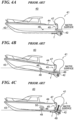
- FIGS. 4A to 4C are views useful in explaining shift of a state of a planing boat equipped with an outboard motor including a conventional reciprocating engine to a planing state.
- a wave is generated due to cutwater of a bow 43 of the planing boat 40, a hull 44 of the planing boat 40 is raised by the wave crest, and a stern 45 of the planing boat 40 falls into a wave hollow, causing the planing boat 40 to be into a hump state in which the bow 43 to be raised relatively ( FIG. 4B ).
- the resistance, wave-making resistance, and viscous resistance acting on the hull 44 increase, making it difficult for the vessel speed to increase, and therefore, no lift is generated at the vessel's bottom, making it difficult for the planing boat 40 to go into the planing state.
- a pitching moment (a counterclockwise moment as viewed in the drawings) as to lower the bow 43 should be generated about a center of gravity 46 of the hull 44 by the propulsive force f.
- the outboard motor 41 of the conventional planing boat 40 is allowed to be trimmed in up to only about 4° about a tilt shaft 47 as described above, and the loading direction of the propulsive force f generated by the propeller 42 provided in a lower portion of the outboard motor 41 is kept below the center of gravity 46.
- a pitching moment 48 generated about the center of gravity 46 by the propulsive force f is a moment clockwise as viewed in the drawings and acts on the hull 44 to raise the bow 43. Note that the pitching moment 48 is indicated by white arrows in the drawings.
- the conventional planing boat 40 is equipped with a trim tab 49 as a posture control plate at the stern 45.
- the trim tab 49 rotates at the stern 45 with respect to the vertical direction of the planing boat 40.
- lift force L is generated in the vicinity of the bow 45 by the trim tab 49 being lowered.
- the lift force L generates a pitching moment 50 (a moment counterclockwise as viewed in the drawing) as to lower the bow 43 about the center of gravity 46 ( FIG. 4C ).
- the bow is lowered, ending the hump state.
- the resistance acting on the hull 44 is decreased to increase the vessel speed, and the lift force generated at the vessel's bottom enables the planing boat 40 to go into the planing state.
- the pitching moment 50 is indicated by a hatched arrow in the drawing.
- FIGS. 5A to 5C are views useful in explaining a shift of a state of a marine vessel 10 equipped with the outboard motor 13 including the electric motor 15 according to the first preferred embodiment, to the planing state.
- the outboard motor 13 is hardly trimmed in, and the loading direction (acting direction) of a propulsive force F generated by the propeller 20 of the outboard motor 13 is parallel or substantially parallel to the water surface ( FIG. 5A ).
- the loading direction of the propulsive force F is indicated by dot-dashed lines, and the water surface is indicated by a solid line.
- the position of the tilt shaft 17 while the marine vessel 10 is sailing is set such that the maximum rotational angle ⁇ 1 is equal to or greater than 20° ( ⁇ 1 ⁇ 20°), and more preferably equal to or greater than 30° ( ⁇ 1 ⁇ 30°).
- the outboard motor main body 16 can be trimmed in to a great extent, and accordingly, the loading direction of the propulsive force F can be turned upward to a great extent.
- the loading direction of the propulsive force F generated by the propeller 20 can be shifted above a center of gravity 24, and hence a pitching moment 25 generated about the center of gravity 24 by the propulsive force F is counterclockwise as viewed in the drawing and acts on the hull 11 to lower the bow 23 ( FIG. 5C ).
- the pitching moment 25 is indicated by a white arrow in the drawing.
- the outboard motor main body 16 can be trimmed in to a great extent, and the propulsive force F can therefore generate the pitching moment 25 for lowering the bow 23.
- the propulsive force F can therefore generate the pitching moment 25 for lowering the bow 23.
- it can eliminate a necessity of use a trim tab for the purpose of ending the hump state, and therefore eliminate the necessity of a trim tab to be placed in the marine vessel 10.
- required output of the electric motor 15 can be reduced, and upsizing of the electric motor 15 can be avoided.
- the second preferred embodiment differs from the first preferred embodiment in that a marine vessel 60 is a hydrofoil boat, not a planing boat.
- the other configurations and operations are basically the same as those of the first preferred embodiment described above, and hence the corresponding configurations and operations will not be described.
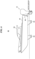
- FIG. 6 is a side view of a marine vessel 60 to which an outboard motor 13 according to the second preferred embodiment is applied.
- FIG. 7 is a side view useful in explaining the outline of a configuration of the outboard motor 13 according to the second preferred embodiment.
- the marine vessel 60 is a hydrofoil, and includes a hull 61 and at least one, for example, two outboard motors 13 as marine propulsion devices to be attached to a stern 62 of the hull 61.
- a cabin 63 also serving as a cockpit is disposed in the hull 61.
- FIG. 6 shows the marine vessel 60 in a foilborne sailing state, but the marine vessel 60 is not limited to the hydrofoil, and may be, for example, a relatively small marine vessel of a displacement type equipped with hydrovanes.
- the marine vessel 60 further has hydrovanes 64.
- the hydrovanes 64 may be configured to be accommodatable into the hull 61.
- the number of hydrovanes 64 is not limited; however, it is preferred that at least two hydrovanes 64 are disposed side by side in the fore-and-aft direction of the marine vessel 60.
- the left side in the figures corresponds to a forward direction of the marine vessel 60
- the right side in the figures corresponds to a rearward direction of the marine vessel 60
- the upper side in the figures corresponds to an upper direction of the marine vessel 60
- the lower side in the figures corresponds to a lower direction of the marine vessel 60
- a depth direction in the figures corresponds to a right direction of the marine vessel 60
- a front direction in the figures corresponds to a left direction of the marine vessel 60.
- the lift mechanism 19 of the outboard motor 13 adjusts the position of the outboard motor main body 16 with respect to the vertical direction via the bracket 18 so that the propeller 20 can be entirely submerged under the water surface.
- the bottom of the marine vessel 60 while foilborne-sailing entirely floats over the water surface as shown in FIG. 6 , which requires the lift mechanism 19 to move the propeller 20 downward to a lower position than the outboard motor 13 (the first preferred embodiment) provided in the marine vessel 10, which is a planing boat.
- the lift mechanism 19 moves the outboard motor main body 16 downward to a lower position, than the position of the outboard motor main body 16 while the marine vessel 10 is sailing (the first preferred embodiment).
- the tilt shaft 17 of the bracket 18 lies at a lower position than the lower end of the stern 62, wherein the distance L6 from the lower end of the stern 62 to the tilt shaft 17 with respect to the vertical direction is equal to or shorter than the distance L1 from the upper end of the stern 62 to the tilt shaft 17.
- the tilt shaft 17 is closer to the lower end of the stern 62 than to the upper end of the stern 62 with respect to the vertical direction.
- the distance L2 from the tilt shaft 17 to the propeller shaft 21 with respect to the vertical direction is equal to or shorter than the distance L1.
- the distance L1 is twice or more as long as the distance L2.
- the outboard motor 13 has the same structure, and hence as with the first preferred embodiment, the distance L4 from the tilt shaft 17 to the lower end of the outboard motor main body 16 with respect to the vertical direction is equal to or shorter than the distance L3 from the tilt shaft 17 to the upper end of the outboard motor main body 16 with respect to the vertical direction.
- the tilt shaft 17 is positioned closer to the bottom. Further, the distance L5 from the rear end of the stern 62 to the tilt shaft 17 with respect to the fore-and-aft direction is greater than zero, as with the first preferred embodiment.
- FIGS. 8A to 8C are views useful in explaining trim-in and tilt-up of the outboard motor main body 16 in the second preferred embodiment.
- the outboard motor main body 16 that has not been trimmed in or tilted up is held by the bracket 18 such that the drive shaft 22 lies along the vertical direction.
- the power tilt trim of the bracket 18 rotates the outboard motor main body 16 clockwise as viewed in the drawing with respect to the tilt shaft 17 ( FIG. 8B ).
- the tilt shaft 17 is disposed closer to the bottom, and the tilt shaft 17 is closer to the lower end of the outboard motor main body 16 than to the upper end of the outboard motor main body 16.
- the amount of the forward movement of the lower portion 16b of the outboard motor main body 16 when the outboard motor main body 16 is trimmed in about the tilt shaft 17, is small.
- the outboard motor main body 16 can be trimmed in to a great extent.
- the position of the tilt shaft 17 while the marine vessel 60 is foilborne-sailing is set such that the maximum trim-in angle ⁇ 1 is equal to or greater than 20° ( ⁇ 1 ⁇ 20°), more preferably equal to or greater than 30° ( ⁇ 1 ⁇ 30°).
- the tilt shaft 17 is moved to a lower position than in the first preferred embodiment, and hence in the second preferred embodiment, the lower portion 16b of the outboard motor main body 16 gets further away from the stern 62 of the hull 61.
- the lower portion 16b of the outboard motor main body 16 is further away from the stern 62 than in the first preferred embodiment, and hence the outboard motor main body 16 can be trimmed in to a greater extent.
- the maximum trim-in angle ⁇ 1 may be set to a greater value than the maximum trim-in angle ⁇ 1 in the first preferred embodiment.
- the lift mechanism 19 raises the outboard motor main body 16 to its uppermost position, and also tilts up the outboard motor main body 16 with respect to the tilt shaft 17 ( FIG. 8C ).
- the outboard motor 13 may be equipped with any of the following in place of an electric motor as a power source: an internal combustion engine in which lubricating oil never goes back to a crankcase and burns even if the outboard motor main body 16 is trimmed in to a great extent, such as a rotary engine and a reciprocating engine disposed such that its cylinder head is never positioned below a cylinder block when the outboard motor main body 16 is trimmed in.
- an internal combustion engine in which lubricating oil never goes back to a crankcase and burns even if the outboard motor main body 16 is trimmed in to a great extent, such as a rotary engine and a reciprocating engine disposed such that its cylinder head is never positioned below a cylinder block when the outboard motor main body 16 is trimmed in.
Landscapes
- Chemical & Material Sciences (AREA)
- Engineering & Computer Science (AREA)
- Combustion & Propulsion (AREA)
- Mechanical Engineering (AREA)
- Ocean & Marine Engineering (AREA)
- Physics & Mathematics (AREA)
- Fluid Mechanics (AREA)
- Actuator (AREA)
- Gear Transmission (AREA)
- Connection Of Motors, Electrical Generators, Mechanical Devices, And The Like (AREA)
Abstract
Description
- The present invention relates to an outboard motor capable of being tilted up and trimmed in, and a marine vessel therewith.
- A relatively small marine vessel such as a planing boat has an outboard motor as a propulsion device. As shown in
FIG. 9A , anoutboard motor 90 includes an outboard motormain body 91 incorporating a power source therein, and abracket 93 provided with atilt shaft 92. Thebracket 93 is attached to astern 98 of ahull 94 of a marine vessel, and the outboard motormain body 91 is attached to thebracket 93 so as to rotate about thetilt shaft 92. Note that inFIG. 9A to FIG. 9C , the left side in the figures corresponds to a forward direction of the marine vessel, the right side in the figures corresponds to a rearward direction of the marine vessel, the upper side in the figures corresponds to an upper direction of the marine vessel, and the lower side in the figures corresponds to a lower direction of the marine vessel. Thetilt shaft 92 extends in the crosswise direction of the marine vessel, and hence the outboard motormain body 91 rotates about thetilt shaft 92 counterclockwise as viewed in the drawing (tilt-up) such that anupper portion 91a moves forward and downward and alower portion 91b moves rearward and upward (FIG. 9A ), or rotates about thetilt shaft 92 clockwise as viewed in the drawing (trim-in) such that theupper portion 91a moves rearward and downward and thelower portion 91b moves forward and upward (FIG. 9B ) (see, for example,Japanese Laid-open Patent Publication (Kokai) No. H01-317893 - Conventionally, a reciprocating engine 95, which is an internal combustion engine, has been used as a power source for the
outboard motor 90. In anupper portion 91a of the outboard motormain body 91, the reciprocating engine 95 is disposed such that a crankshaft lies along the vertical direction and acylinder head 96 lies behind a cylinder block 97 (FIG. 9A ). Thus, when the outboard motormain body 91 is trimmed in to a great extent, at least a part of thecylinder head 96 becomes positioned at a lower position than the cylinder block 97. Therefore, lubricating oil for a cylinder in the cylinder block 97 may be burned in a fuel chamber without going back to a crankcase, and as a result, the reciprocating engine 95 may blow white smoke. For this reason, in theoutboard motor 90 using the reciprocating engine 95, it is difficult for the outboard motormain body 91 to trim in to a great extent. - Implementation of carbon-free mobile bodies as one of means for achieving recently-advocated SDGs (Sustainable Development Goals) has been pursued, and as a power source for an automobile which is as an example of mobile bodies, an internal combustion engine is being increasingly replaced with an electric motor.
- As the power source of the
outboard motor 90, it has also been studied to replace an internal combustion engine with an electric motor as with the automobile. If the power source of theoutboard motor 90 is replaced with an electric motor, the combustion of the lubricating oil described above will never happen, which will make it unnecessary to limit the amount of trim-in so as to prevent the white smoke. Trim-in has a significant effect on posture control in the pitch direction while the marine vessel is sailing, and hence in theoutboard motor 90 using an electric motor as the power source, the outboard motormain body 91 is required to be trimmed in to a great extent from the standpoint of increasing the degree of freedom in posture control. - On the other hand, for the
conventional outboard motor 90, the outboard motormain body 91 is required to be tilted up to a great extent since priority is given to lifting the outboard motormain body 91 out of water when the marine vessel is anchored at a pier or the like for a long period of time. Accordingly, in a conventional technique, by placing thetilt shaft 92 in the vicinity of theupper portion 91a of the outboard motormain body 91, even if the outboard motormain body 91 is tilted up to a great extent, the amount of movement to forward of theupper portion 91a of the outboard motormain body 91 is kept small so that theupper portion 91a of the outboard motormain body 91 is prevented from interfering with the hull 94 (FIG. 9B ). - However, if the
tilt shaft 92 is placed in the vicinity of theupper portion 91a of the outboard motormain body 91, thelower portion 91b of the outboard motormain body 91 moves forward by a large amount when the outboard motormain body 91 is trimmed in, and therefore, even when the amount of trim-in is increased only a little, thelower portion 91b of the outboard motormain body 91 may interfere with the hull 94 (FIG. 9C ). Thus, in theconventional outboard motor 90, it is difficult to increase the amount (angle) of the trim-in of the outboard motormain body 91, and the outboard motormain body 91 is allowed to be trimmed in up to only about 4° about thetilt shaft 92. Namely, there is room for improvement regarding the amount of trim-in that can be achieved. - It is the object of the present invention to provide an outboard motor that can achieve a great trim-in of the main body of the outboard motor.
- According to the present invention said object is solved by an outboard motor having the features of the
independent claim 1. As an alternative solution of said object, it is provided an outboard motor having the features of theindependent claim 12 or an outboard motor having the features of theindependent claim 13. Preferred embodiments are laid down in the dependent claims. - According to a preferred embodiment, an outboard motor comprising a main body that incorporates a power source therein, and a bracket that includes a rotating shaft, wherein the bracket is to be attached to a stern of a hull of a marine vessel, wherein: the main body is attached to the bracket so as to be able to rotate a first rotation and a second rotation; a propeller shaft for rotating a propeller is provided at a lower portion of the main body; in the first rotation, the main body rotates about the rotating shaft such that an upper portion of the main body moves toward the front of the marine vessel and a lower portion of the main body moves toward the rear of the marine vessel; in the second rotation, the main body rotates about the rotating shaft such that the upper portion of the main body moves toward the rear of the marine vessel and the lower portion of the main body moves toward the front of the marine vessel; and while the marine vessel is sailing, a first distance from the rotating shaft to an upper end of the stern with respect to a vertical direction of the marine vessel is equal to or longer than a second distance from the rotating shaft to the propeller shaft with respect to the vertical direction of the marine vessel.
- According to another preferred embodiment, an outboard motor comprising a main body that incorporates a power source therein, and a bracket that includes a rotating shaft, wherein the bracket is to be attached to a stern of a hull of a marine vessel, wherein: the main body is attached to the bracket so as to be able to rotate a first rotation and a second rotation; in the first rotation, the main body rotates about the rotating shaft such that an upper portion of the main body moves toward the front of the marine vessel and a lower portion of the main body moves toward the rear of the marine vessel; in the second rotation, the main body rotates about the rotating shaft such that the upper portion of the main body moves toward the rear of the marine vessel and the lower portion of the main body moves toward the front of the marine vessel; and with respect to a vertical direction of the marine vessel, the rotating shaft is disposed closer to a lower end of the stern than to an upper end of the stern.
- According to another preferred embodiment, an outboard motor comprising a main body that incorporates a power source therein, and a bracket that includes a rotating shaft, wherein the bracket is to be attached to a stern of a hull of a marine vessel, wherein: the main body is attached to the bracket so as to be able to rotate a first rotation and a second rotation; in the first rotation, the main body rotates about the rotating shaft such that an upper portion of the main body moves toward the front of the marine vessel and a lower portion of the main body moves toward the rear of the marine vessel; in the second rotation, the main body rotates about the rotating shaft such that the upper portion of the main body moves toward the rear of the marine vessel and the lower portion of the main body moves toward the front of the marine vessel; and with respect to a vertical direction of the marine vessel, the rotating shaft is disposed closer to a lower end of the main body than to an upper end of the main body.
- According to the configuration described above,: while the marine vessel is sailing, the first distance from the rotating shaft to the upper end of the stern with respect to the vertical direction of the marine vessel is equal to or longer than the second distance from the rotating shaft to the propeller shaft with respect to the vertical direction of the marine vessel; the rotating shaft is disposed closer to the lower end of the stern than to the upper end of the stern with respect to the vertical direction of the marine vessel; or the rotating shaft is disposed closer to the lower end of the main body than to the upper end of the main body with respect to the vertical direction of the marine vessel. Namely, the rotating shaft of the main body of the outboard motor is disposed closer to the bottom with respect to the vertical direction of the marine vessel. Therefore, the amount of the forward movement of the lower portion of the main body when the outboard motor is rotated about the rotating shaft such that the lower portion of the main body of the outboard motor moves forward of the marine vessel (trimmed in) is small, and hence even if the amount of trim-in is increased, the lower portion of the main body can be prevented from interfering with the hull. As a result, the main body of the outboard motor can be trimmed in to a great extent.
- Further features of the present teaching will become apparent from the following description of a preferred embodiment (with reference to the attached drawings).
- The above and other elements, features, steps, characteristics and advantages of the present teaching will become more apparent from the following detailed description of the preferred embodiment with reference to the attached drawings.
-
-
FIG. 1 is a side view of a marine vessel to which an outboard motor according to a first preferred embodiment is applied. -
FIG. 2 is a side view useful in explaining the outline of a configuration of the outboard motor according to the first preferred embodiment. -
FIGS. 3A to 3C are views useful in explaining trim-in and tilt-up of an outboard motor main body in the first preferred embodiment. -
FIGS. 4A to 4C are views useful in explaining shift of a state of a planing boat equipped with an outboard motor including a conventional reciprocating engine to a planing state. -
FIGS. 5A to 5C are views useful in explaining a shift of a state of a marine vessel equipped with an outboard motor including an electric motor according to the first preferred embodiment, to the planing state. -
FIG. 6 is a side view of a marine vessel to which an outboard motor according to a second preferred embodiment is applied. -
FIG. 7 is a side view useful in explaining the outline of a configuration of the outboard motor according to the second preferred embodiment. -
FIGS. 8A to 8C are views useful in explaining trim-in and tilt-up of an outboard motor main body in the second preferred embodiment. -
FIGS. 9A to 9C are views useful in explaining trim-in and tilt-up of a conventional outboard motor main body. - Hereafter, preferred embodiments will be described with reference to the drawings. A description will now be given of a first preferred embodiment.
-
FIG. 1 is a side view of amarine vessel 10 to which anoutboard motor 13 according to the first preferred embodiment is applied.FIG. 2 is a side view useful in explaining the outline of a configuration of theoutboard motor 13 according to the first preferred embodiment. - The
marine vessel 10 is, for example, a plaining boat, and includes ahull 11 and at least one, for example, twooutboard motors 13 as marine propulsion devices to be attached to astern 12 of thehull 11. Acabin 14 also serving as a cockpit is disposed in thehull 11. AlthoughFIG. 1 shows themarine vessel 10 in a plaining state, themarine vessel 10 is not limited to a planing boat, but may be, for example, a relatively small marine vessel of a displacement type. - Note that in the drawings to be referred to below, the left side in the figures corresponds to a forward direction of the
marine vessel 10, the right side in the figures corresponds to a rearward direction of themarine vessel 10, the upper side in the figures corresponds to an upper direction of themarine vessel 10, and the lower side in the figures corresponds to a lower direction of themarine vessel 10, a depth direction in the figures corresponds to a right direction of themarine vessel 10, and a front direction in the figures corresponds to a left direction of themarine vessel 10. - The
outboard motor 13 includes an outboard motormain body 16 incorporating anelectric motor 15 as a power source therein, abracket 18 provided with a tilt shaft 17 (rotating shaft), and alift mechanism 19 attached to the stern 12 of thehull 11. In the outboard motormain body 16, theelectric motor 15 is disposed in anupper portion 16a. The outboard motormain body 16 further includes apropeller 20 and apropeller shaft 21 for rotating thepropeller 20, disposed in alower portion 16b, and adrive shaft 22 that transmits a driving force of theelectric motor 15 to thepropeller shaft 21. Thepropeller 20 rotated by the driving force of theelectric motor 15 applies a propulsive force to themarine vessel 10. Thepropeller shaft 21 is disposed along the fore-and-aft of themarine vessel 10, and thedrive shaft 22 is disposed along the vertical direction of themarine vessel 10 - A steering mechanism (not illustrated) is provided in the
outboard motor 13, and by swinging theoutboard motor 13 in the crosswise direction of themarine vessel 10 with respect to thehull 11, adjusts the direction in which a propulsive force generated by theoutboard motor 13 acts with respect to the crosswise direction. - The
bracket 18 is attached to the stern 12 of thehull 11 via thelift mechanism 19, wherein thelift mechanism 19 moves thebracket 18 with respect to the vertical direction of themarine vessel 10. The outboard motormain body 16 is attached to thebracket 18. As a result, thelift mechanism 19 moves the outboard motormain body 16 via thebracket 18 with respect to the vertical direction of themarine vessel 10. - The outboard motor
main body 16 is attached to thebracket 18 rotatably about thetilt shaft 17. Thetilt shaft 17 extends in the crosswise direction of themarine vessel 10, and hence the outboard motormain body 16 rotates about thetilt shaft 17 counterclockwise as viewed in the drawing (first rotation) such that theupper portion 16a moves forward and downward of themarine vessel 10 and thelower portion 16b moves rearward and upward of themarine vessel 10, or rotates about thetilt shaft 17 clockwise as viewed in the drawing (second rotation) such that theupper portion 16a moves rearward and downward of themarine vessel 10 and thelower portion 16b moves forward and upward of themarine vessel 10. Note that the first rotation will be referred to as "tilt-up", and the second rotation will be referred to as "trim-in". - The
bracket 18 comprises a rotational mechanism, such as a power tilt trim (not illustrated), including a hydraulic actuator for tilting up the outboard motormain body 16 and a hydraulic actuator for trimming in the outboard motormain body 16. Thelift mechanism 19 includes a hydraulic actuator (not illustrated) for moving up and down thebracket 18. - While the
marine vessel 10 is sailing, thelift mechanism 19 adjusts (changes) the position of the outboard motormain body 16 with respect to the vertical direction via thebracket 18 so that thepropeller 20 can be entirely submerged under the water surface. At this time, the distance L6 from thetilt shaft 17 to the lower end of the stern 12 with respect to the vertical direction is equal to or shorter than the distance L1 (first distance) from thetilt shaft 17 to the upper end of the stern 12 with respect to the vertical direction. Namely, thetilt shaft 17 is closer to the lower end of the stern 12 than to the upper end of the stern 12 with respect to the vertical direction. Moreover, the distance L2 (second distance) from thetilt shaft 17 to thepropeller shaft 21 with respect to the vertical direction is equal to or shorter than the distance L1. Further, the distance L4 from thetilt shaft 17 to the lower end of the outboard motormain body 16 with respect to the vertical direction is equal to or shorter than the distance L3 from thetilt shaft 17 to the upper end of the outboard motormain body 16 with respect to the vertical direction. Namely, thetilt shaft 17 is closer to the lower end of the outboard motormain body 16 than to the upper end of the outboard motormain body 16 with respect to the vertical direction. In addition, the distance L5 from the rear end of the stern 12 to thetilt shaft 17 with respect to the fore-and-aft direction is greater than zero. Namely, thetilt shaft 17 is disposed at more rear than the rear end of the stern 12 with respect to the fore-and-aft direction. -
FIGS. 3A to 3C are views useful in explaining trim-in and tilt-up of the outboard motormain body 16 in the first preferred embodiment. - As shown in
FIG. 3A , while themarine vessel 10 is sailing, the outboard motormain body 16 that has not been trimmed in or tilted up is held by thebracket 18 such that thedrive shaft 22 lies along the vertical direction. When a vessel operator or the like instructs to trim in the outboard motormain body 16, the power tilt trim of thebracket 18 rotates the outboard motormain body 16 clockwise as viewed in the drawing with respect to the tilt shaft 17 (FIG. 3B ). - Here, as described above, with respect to the vertical direction, the
tilt shaft 17 is closer to the lower end of the stern 12 than to the upper end of the stern 12, and the distance L2 from thetilt shaft 17 to thepropeller shaft 21 with respect to the vertical direction is equal to or shorter than the distance L1 from thetilt shaft 17 to the upper end of the stern 12 with respect to the vertical direction. Namely, thetilt shaft 17 is disposed closer to the bottom, and in the outboard motormain body 16, thetilt shaft 17 is closer to the lower end of the outboard motormain body 16 than to the upper end of the outboard motormain body 16. Thus, the distance from thetilt shaft 17 to the lower end of the outboard motormain body 16 is short, and hence the amount of the forward movement of thelower portion 16b of the outboard motormain body 16 when the outboard motormain body 16 is trimmed in about thetilt shaft 17, is small. As a result, even if the amount of trim-in is increased, the interference of thelower portion 16b with the stern 12 can be prevented, and the outboard motormain body 16 can be trimmed in to a great extent. - Moreover, in the present preferred embodiment, the
tilt shaft 17 is disposed at more rear than the rear end of the stern 12 with respect to the fore-and-aft direction, as described above. In this arrangement, the outboard motormain body 16 is away from the stern 12, which makes thelower portion 16b less likely to interfere with the stern 12 when the outboard motormain body 16 is trimmed in about thetilt shaft 17. Therefore, placing thetilt shaft 17 at more rear than the rear end of the stern 12 with respect to the fore-and-aft direction contributes to achieving a great trim-in of the outboard motormain body 16. - In this way, in the present preferred embodiment, the great trim-in of the outboard motor
main body 16 can be achieved. Specifically, the position of thetilt shaft 17 while themarine vessel 10 is sailing is set such that the maximum rotational angle θ1 (maximum trim-in angle) is equal to or greater than 20° (θ1 ≥ 20°), more preferably equal to or greater than 30° (θ1 ≥ 30°), wherein at the maximum rotational angle θ1, thelower portion 16b of the outboard motormain body 16 does not interfere with the stern 12 of thehull 11 or thebracket 18 when the outboard motormain body 16 is rotated clockwise as viewed in the drawings with respect to thetilt shaft 17 from the state in which thedrive shaft 22 lies along the vertical direction (neutral state). - To anchor the
marine vessel 10 at a pier for a long period of time for storage, the outboard motormain body 16 is lifted out of water. In this case, thelift mechanism 19 raises the outboard motormain body 16 to its uppermost position via thebracket 18, and further, the power tilt trim of thebracket 18 tilts up the outboard motormain body 16 with respect to the tilt shaft 17 (FIG. 3C ). At this time, with the upward movement of thebracket 18, thetilt shaft 17 is positioned closer to the upper side, and hence even if the amount of tilt-up is increased, theupper portion 16a of the outboard motormain body 16 can be prevented from interfering with the stern 12, by which the great tilt-up of the outboard motormain body 16 can be achieved. As a result, thelower portion 16b of the outboard motormain body 16 can be relatively moved upward to a great extent, enabling thepropeller 20 to reliably leave water. -
FIGS. 4A to 4C are views useful in explaining shift of a state of a planing boat equipped with an outboard motor including a conventional reciprocating engine to a planing state. - When a
conventional planing boat 40 is sailing at low speed, lift force is hardly generated at a vessel's bottom, and hence as with a marine vessel of a displacement type, water draft has a predetermined depth. At this time, anoutboard motor 41 is hardly trimmed in, and the loading direction (acting direction) of a propulsive force f generated by apropeller 42 of theoutboard motor 41 is parallel or substantially parallel to the water surface (FIG. 4A ). Note that inFIG. 4A to FIG. 4C , the loading direction of the propulsive force f is indicated by dot-dashed lines, and the water surface is indicated by a solid line. - When the vessel speed increases, a wave is generated due to cutwater of a
bow 43 of the planingboat 40, ahull 44 of the planingboat 40 is raised by the wave crest, and a stern 45 of the planingboat 40 falls into a wave hollow, causing the planingboat 40 to be into a hump state in which thebow 43 to be raised relatively (FIG. 4B ). In the hump state, the resistance, wave-making resistance, and viscous resistance acting on thehull 44 increase, making it difficult for the vessel speed to increase, and therefore, no lift is generated at the vessel's bottom, making it difficult for the planingboat 40 to go into the planing state. To end the hump state, for example, a pitching moment (a counterclockwise moment as viewed in the drawings) as to lower thebow 43 should be generated about a center ofgravity 46 of thehull 44 by the propulsive force f. - However, the
outboard motor 41 of theconventional planing boat 40 is allowed to be trimmed in up to only about 4° about atilt shaft 47 as described above, and the loading direction of the propulsive force f generated by thepropeller 42 provided in a lower portion of theoutboard motor 41 is kept below the center ofgravity 46. As a result, a pitchingmoment 48 generated about the center ofgravity 46 by the propulsive force f is a moment clockwise as viewed in the drawings and acts on thehull 44 to raise thebow 43. Note that the pitchingmoment 48 is indicated by white arrows in the drawings. - Accordingly, the
conventional planing boat 40 is equipped with atrim tab 49 as a posture control plate at the stern 45. Thetrim tab 49 rotates at the stern 45 with respect to the vertical direction of the planingboat 40. In theconventional planing boat 40, lift force L is generated in the vicinity of thebow 45 by thetrim tab 49 being lowered. The lift force L generates a pitching moment 50 (a moment counterclockwise as viewed in the drawing) as to lower thebow 43 about the center of gravity 46 (FIG. 4C ). As a result, the bow is lowered, ending the hump state. As a result, the resistance acting on thehull 44 is decreased to increase the vessel speed, and the lift force generated at the vessel's bottom enables the planingboat 40 to go into the planing state. Note that the pitchingmoment 50 is indicated by a hatched arrow in the drawing. - When the
trim tab 49 is lowered, the resistance acting on thetrim tab 49 increases, and hence the reciprocating engine of theoutboard motor 41 is required to have high power output, leading to upsizing of the reciprocating engine and upsizing of theoutboard motor 41. On the other hand, in themarine vessel 10 equipped with theoutboard motor 13 using theelectric motor 15 according to the present preferred embodiment, it is unnecessary to use a trim tab so as to end the hump state. A detailed description thereof will be given below. -
FIGS. 5A to 5C are views useful in explaining a shift of a state of amarine vessel 10 equipped with theoutboard motor 13 including theelectric motor 15 according to the first preferred embodiment, to the planing state. - As with the plaining
boat 40, when themarine vessel 10 is sailing at low speed, lift force is hardly generated at the vessel's bottom, and hence water draft has a predetermined depth. At this time, theoutboard motor 13 is hardly trimmed in, and the loading direction (acting direction) of a propulsive force F generated by thepropeller 20 of theoutboard motor 13 is parallel or substantially parallel to the water surface (FIG. 5A ). Note that inFIG. 5A to FIG. 5C , the loading direction of the propulsive force F is indicated by dot-dashed lines, and the water surface is indicated by a solid line. - When the vessel speed increases, a wave is generated due to cutwater of a
bow 23 of themarine vessel 10, causing themarine vessel 10 to be into a hump state in which thebow 23 to be raised relatively (FIG. 5B ). As described above, in theoutboard motor 13, the position of thetilt shaft 17 while themarine vessel 10 is sailing is set such that the maximum rotational angle θ1 is equal to or greater than 20° (θ1 ≥ 20°), and more preferably equal to or greater than 30° (θ1 ≥ 30°). As a result, the outboard motormain body 16 can be trimmed in to a great extent, and accordingly, the loading direction of the propulsive force F can be turned upward to a great extent. Thus, the loading direction of the propulsive force F generated by thepropeller 20 can be shifted above a center ofgravity 24, and hence apitching moment 25 generated about the center ofgravity 24 by the propulsive force F is counterclockwise as viewed in the drawing and acts on thehull 11 to lower the bow 23 (FIG. 5C ). Note that the pitchingmoment 25 is indicated by a white arrow in the drawing. - That is, in the present preferred embodiment, the outboard motor
main body 16 can be trimmed in to a great extent, and the propulsive force F can therefore generate thepitching moment 25 for lowering thebow 23. As a result, it can eliminate a necessity of use a trim tab for the purpose of ending the hump state, and therefore eliminate the necessity of a trim tab to be placed in themarine vessel 10. Moreover, required output of theelectric motor 15 can be reduced, and upsizing of theelectric motor 15 can be avoided. - A description will now be given of a second preferred embodiment. The second preferred embodiment differs from the first preferred embodiment in that a
marine vessel 60 is a hydrofoil boat, not a planing boat. The other configurations and operations are basically the same as those of the first preferred embodiment described above, and hence the corresponding configurations and operations will not be described. -
FIG. 6 is a side view of amarine vessel 60 to which anoutboard motor 13 according to the second preferred embodiment is applied.FIG. 7 is a side view useful in explaining the outline of a configuration of theoutboard motor 13 according to the second preferred embodiment. - The
marine vessel 60 is a hydrofoil, and includes ahull 61 and at least one, for example, twooutboard motors 13 as marine propulsion devices to be attached to a stern 62 of thehull 61. Acabin 63 also serving as a cockpit is disposed in thehull 61.FIG. 6 shows themarine vessel 60 in a foilborne sailing state, but themarine vessel 60 is not limited to the hydrofoil, and may be, for example, a relatively small marine vessel of a displacement type equipped with hydrovanes. - The
marine vessel 60 further hashydrovanes 64. Thehydrovanes 64 may be configured to be accommodatable into thehull 61. The number ofhydrovanes 64 is not limited; however, it is preferred that at least twohydrovanes 64 are disposed side by side in the fore-and-aft direction of themarine vessel 60. When the speed of themarine vessel 60 increases, lift force generated by thehydrovanes 64 increases, causing thehull 61 to leave water and causing themarine vessel 60 to go into the foilborne sailing state. - Note that in the drawings to be referred to below, the left side in the figures corresponds to a forward direction of the
marine vessel 60, the right side in the figures corresponds to a rearward direction of themarine vessel 60, the upper side in the figures corresponds to an upper direction of themarine vessel 60, and the lower side in the figures corresponds to a lower direction of themarine vessel 60, a depth direction in the figures corresponds to a right direction of themarine vessel 60, and a front direction in the figures corresponds to a left direction of themarine vessel 60. - As with the first preferred embodiment, while the
marine vessel 60 is foilborne-sailing, thelift mechanism 19 of theoutboard motor 13 adjusts the position of the outboard motormain body 16 with respect to the vertical direction via thebracket 18 so that thepropeller 20 can be entirely submerged under the water surface. The bottom of themarine vessel 60 while foilborne-sailing entirely floats over the water surface as shown inFIG. 6 , which requires thelift mechanism 19 to move thepropeller 20 downward to a lower position than the outboard motor 13 (the first preferred embodiment) provided in themarine vessel 10, which is a planing boat. - Specifically, in order to move the
propeller 20 downward, thelift mechanism 19 moves the outboard motormain body 16 downward to a lower position, than the position of the outboard motormain body 16 while themarine vessel 10 is sailing (the first preferred embodiment). Thus, in the second preferred embodiment, as distinct from the first preferred embodiment, thetilt shaft 17 of thebracket 18 lies at a lower position than the lower end of the stern 62, wherein the distance L6 from the lower end of the stern 62 to thetilt shaft 17 with respect to the vertical direction is equal to or shorter than the distance L1 from the upper end of the stern 62 to thetilt shaft 17. In other words, also in the second preferred embodiment, thetilt shaft 17 is closer to the lower end of the stern 62 than to the upper end of the stern 62 with respect to the vertical direction. Moreover, the distance L2 from thetilt shaft 17 to thepropeller shaft 21 with respect to the vertical direction is equal to or shorter than the distance L1. Specifically, the distance L1 is twice or more as long as the distance L2. Note that in the first preferred embodiment and the second preferred embodiment, theoutboard motor 13 has the same structure, and hence as with the first preferred embodiment, the distance L4 from thetilt shaft 17 to the lower end of the outboard motormain body 16 with respect to the vertical direction is equal to or shorter than the distance L3 from thetilt shaft 17 to the upper end of the outboard motormain body 16 with respect to the vertical direction. Namely, also in the second preferred embodiment, thetilt shaft 17 is positioned closer to the bottom. Further, the distance L5 from the rear end of the stern 62 to thetilt shaft 17 with respect to the fore-and-aft direction is greater than zero, as with the first preferred embodiment. -
FIGS. 8A to 8C are views useful in explaining trim-in and tilt-up of the outboard motormain body 16 in the second preferred embodiment. - As shown in
FIG.8A , while themarine vessel 60 is foilborne-sailing, the outboard motormain body 16 that has not been trimmed in or tilted up is held by thebracket 18 such that thedrive shaft 22 lies along the vertical direction. When a vessel operator or the like instructs to trim in the outboard motormain body 16, the power tilt trim of thebracket 18 rotates the outboard motormain body 16 clockwise as viewed in the drawing with respect to the tilt shaft 17 (FIG. 8B ). - As described above, also in the second preferred embodiment, the
tilt shaft 17 is disposed closer to the bottom, and thetilt shaft 17 is closer to the lower end of the outboard motormain body 16 than to the upper end of the outboard motormain body 16. Thus, the amount of the forward movement of thelower portion 16b of the outboard motormain body 16 when the outboard motormain body 16 is trimmed in about thetilt shaft 17, is small. As a result, as with the first preferred embodiment, the outboard motormain body 16 can be trimmed in to a great extent. Also in the second embodiment, the position of thetilt shaft 17 while themarine vessel 60 is foilborne-sailing is set such that the maximum trim-in angle θ1 is equal to or greater than 20° (θ1 ≥ 20°), more preferably equal to or greater than 30° (θ1 ≥ 30°). Note that in the second preferred embodiment, thetilt shaft 17 is moved to a lower position than in the first preferred embodiment, and hence in the second preferred embodiment, thelower portion 16b of the outboard motormain body 16 gets further away from the stern 62 of thehull 61. In the second preferred embodiment, thelower portion 16b of the outboard motormain body 16 is further away from the stern 62 than in the first preferred embodiment, and hence the outboard motormain body 16 can be trimmed in to a greater extent. Accordingly, in the second preferred embodiment, the maximum trim-in angle θ1 may be set to a greater value than the maximum trim-in angle θ1 in the first preferred embodiment. - Note that as with the first preferred embodiment, to anchor the
marine vessel 60 at a pier for a long period of time, thelift mechanism 19 raises the outboard motormain body 16 to its uppermost position, and also tilts up the outboard motormain body 16 with respect to the tilt shaft 17 (FIG. 8C ). - As an alternative with regard to the embodiment, the
outboard motor 13 may be equipped with any of the following in place of an electric motor as a power source: an internal combustion engine in which lubricating oil never goes back to a crankcase and burns even if the outboard motormain body 16 is trimmed in to a great extent, such as a rotary engine and a reciprocating engine disposed such that its cylinder head is never positioned below a cylinder block when the outboard motormain body 16 is trimmed in.
Claims (14)
- An outboard motor (13) configured to be attached to a marine vessel (10, 60) having a hull (11, 61) with a stern (12, 62), comprising:a main body (16) that incorporates a power source (15) therein; anda bracket (18) that includes a rotating shaft (17), wherein the bracket (18) is configured to be attached to the stern (12, 62), whereinthe main body (16) is attached to the bracket (18) so as to be able to rotate a first rotation and a second rotation about the rotation shaft (17),a propeller shaft (21) for rotating a propeller (20) is provided at a lower portion (16b) of the main body (16),in the first rotation, the main body (16) rotates about the rotating shaft (17) such that an upper portion (16a) of the main body (16) with regard to a vertical direction of the marine vessel (10, 60) moves toward the stern (12, 62) of the marine vessel (10, 60) and a lower portion (16b) of the main body (16) with regard to a vertical direction of the marine vessel (10, 60) moves away from the stern (12, 62) of the marine vessel (10, 60),in the second rotation, the main body (16) rotates about the rotating shaft (17) such that the upper portion (16a) of the main body (16) moves away from the stern (12, 62) of the marine vessel (10, 60) and the lower portion (16b) of the main body (16) moves toward the stern (12, 62) of the marine vessel (10, 60), andwhile the marine vessel (10, 60) is sailing, a first distance (L1) from the rotating shaft (17) to an upper end of the stern (12, 62) with respect to a vertical direction of the marine vessel (10, 60) is equal to or longer than a second distance (L2) from the rotating shaft (17) to the propeller shaft (21) with respect to the vertical direction of the marine vessel (10, 60).
- The outboard motor (13) according to claim 1, wherein while the marine vessel (10, 60) is sailing, the first distance (L1) is twice or more as long as the second distance (L2).
- The outboard motor (13) according to claim 1 or 2, wherein with respect to a fore-and-aft direction of the hull (11, 61), the rotating shaft (17) is disposed at more rear than a rear end of the stern (12, 62).
- The outboard motor (13) according to at least one of the claims 1 to 3, wherein in the second rotation, the main body (16) rotates about the rotating shaft (17) by a rotation angle of 20° or more.
- The outboard motor (13) according to at least one of the claims 1 to 4, wherein in the second rotation, the main body (16) rotates about the rotating shaft (17) by a rotation angle of 30° or more.
- The outboard motor (13) according to at least one of the claims 1 to 5, wherein a posture control plate that rotates with respect the vertical direction of the marine vessel (10, 60) is not disposed at the stern (12, 62) of the hull (11, 61).
- The outboard motor (13) according to at least one of the claims 1 to 6, further comprising a lift mechanism (19) that is configured to move the main body (16) with respect to the vertical direction of the marine vessel (10, 60).
- The outboard motor (13) according to claim 7, wherein the lift mechanism (19) is configured for changing a position of the main body (16) with respect to the vertical direction of the marine vessel (60) while the marine vessel (60) is sailing.
- The outboard motor (13) according to claim 7 or 8, wherein the marine vessel (60) comprises hydrovanes (64), and the lift mechanism (19) is configured to move the main body (16) downward to a lower side of the hull (11, 61) while the marine vessel (60) is foilborne-sailing.
- The outboard motor (13) according to at least one of the claims 7 to 9, wherein the lift mechanism (19) is configured to raise the main body (16), and the main body (16) rotates the first rotation.
- The outboard motor (13) according to at least one of the claims claim 1 to 10, wherein the power source is an electric motor (15).
- An outboard motor (13) configured to be attached to a marine vessel (10, 60) having a hull (11, 61) with a stern (12, 62), comprising:a main body (16) that incorporates a power source (15) therein; anda bracket (18) that includes a rotating shaft (17), wherein the bracket (18) is configured to be attached to the stern (12, 62), whereinthe main body (16) is attached to the bracket (18) so as to be able to rotate a first rotation and a second rotation about the rotation shaft (17),in the first rotation, the main body (16) rotates about the rotating shaft (17) such that an upper portion (16a) of the main body (16) with regard to a vertical direction of the marine vessel (10, 60) moves toward the stern (12, 62) of the marine vessel (10, 60) and a lower portion (16b) of the main body (16) with regard to a vertical direction of the marine vessel (10, 60) moves away from the stern (12, 62) of the marine vessel (10, 60),in the second rotation, the main body (16) rotates about the rotating shaft (17) such that the upper portion (16a) of the main body (16) moves away from the stern (12, 62) of the marine vessel (10, 60) and the lower portion (16b) of the main body (16) moves toward the stern (12, 62) of the marine vessel (10, 60), andwith respect to the vertical direction of the marine vessel (10, 60), the rotating shaft (17) is disposed closer to a lower end of the stern (12, 62) than to an upper end of the stern (12, 62).
- An outboard motor (13) configured to be attached to a marine vessel (10, 60) having a hull (11, 61) with a stern (12, 62), comprising:a main body (16) that incorporates a power source (15) therein; anda bracket (18) that includes a rotating shaft (17), wherein the bracket (18) is configured to be attached to the stern (12, 62), whereinthe main body (16) is attached to the bracket (18) so as to be able to rotate a first rotation and a second rotation,in the first rotation, the main body (16) rotates about the rotating shaft (17) such that an upper portion (16a) of the main body (16) with regard to a vertical direction of the marine vessel (10, 60) moves toward the stern (12, 62) of the marine vessel (10, 60) and a lower portion (16b) of the main body (16) with regard to a vertical direction of the marine vessel (10, 60) moves away from the stern (12, 62) of the marine vessel (10, 60),in the second rotation, the main body (16) rotates about the rotating shaft (17) such that the upper portion (16a) of the main body (16) moves away from the stern (12, 62) of the marine vessel (10, 60) and the lower portion (16b) of the main body (16) moves toward the stern (12, 62) of the marine vessel (10, 60), andwith respect to the vertical direction of the marine vessel (10, 60), the rotating shaft (17) is disposed closer to a lower end of the main body (16) than to an upper end of the main body (16).
- A marine vessel (10, 60) equipped with an outboard motor (13) according to at least one of the claims 1 to 13.
Applications Claiming Priority (1)
| Application Number | Priority Date | Filing Date | Title |
|---|---|---|---|
| JP2022036644A JP2023131734A (en) | 2022-03-09 | 2022-03-09 | Outboard motors and ships |
Publications (2)
| Publication Number | Publication Date |
|---|---|
| EP4242097A1 true EP4242097A1 (en) | 2023-09-13 |
| EP4242097B1 EP4242097B1 (en) | 2026-05-06 |
Family
ID=85227285
Family Applications (1)
| Application Number | Title | Priority Date | Filing Date |
|---|---|---|---|
| EP23156258.8A Active EP4242097B1 (en) | 2022-03-09 | 2023-02-13 | Outboard motor capable of being tilted up and trimmed in, and marine vessel therewith |
Country Status (3)
| Country | Link |
|---|---|
| US (1) | US20230286634A1 (en) |
| EP (1) | EP4242097B1 (en) |
| JP (1) | JP2023131734A (en) |
Families Citing this family (4)
| Publication number | Priority date | Publication date | Assignee | Title |
|---|---|---|---|---|
| US12326735B2 (en) * | 2021-07-23 | 2025-06-10 | Seakeeper, Inc. | Dynamic active control system with engine control |
| EP4198011B1 (en) * | 2021-12-17 | 2024-07-31 | Evonik Oxeno GmbH & Co. KG | Method for hydroformylation of olefins using pt and dpephos |
| EP4198008B1 (en) * | 2021-12-17 | 2024-07-31 | Evonik Oxeno GmbH & Co. KG | Method for hydroformylation of olefins using pt and iodine |
| ES2991131T3 (en) * | 2021-12-17 | 2024-12-03 | Evonik Oxeno Gmbh & Co Kg | Procedure for the hydroformylation of olefins using Pt and bromine |
Citations (4)
| Publication number | Priority date | Publication date | Assignee | Title |
|---|---|---|---|---|
| JPH01317893A (en) | 1988-06-17 | 1989-12-22 | Sanshin Ind Co Ltd | Device for tilting ship propeller |
| US20160368579A1 (en) * | 2014-02-26 | 2016-12-22 | Kurt D. Willows | System and apparatus for outboard watercraft trim control |
| WO2021032277A1 (en) * | 2019-08-19 | 2021-02-25 | Volvo Penta Corporation | Hydrofoil system and marine vessel |
| US20210086875A1 (en) * | 2019-09-24 | 2021-03-25 | Yamaha Hatsudoki Kabushiki Kaisha | Posture control system for hull, posture control method for the hull, and marine vessel |
Family Cites Families (11)
| Publication number | Priority date | Publication date | Assignee | Title |
|---|---|---|---|---|
| US1021408A (en) * | 1911-07-17 | 1912-03-26 | Jewel Electric Co | Boat steering and propelling device. |
| US1789415A (en) * | 1929-11-08 | 1931-01-20 | Phillips Price Eugene | Outboard motor for boats |
| US1894710A (en) * | 1931-03-28 | 1933-01-17 | Charles B Samuelson | Outboard propelling motor for boats |
| US2079871A (en) * | 1935-07-03 | 1937-05-11 | Harold W Price | Outboard motor |
| US2928630A (en) * | 1955-09-12 | 1960-03-15 | Cletus G Hartman | Assembly for supporting an outboard motor |
| US3145003A (en) * | 1962-08-28 | 1964-08-18 | Mcculloch Corp | Outboard motor mounting |
| US3421723A (en) * | 1968-02-01 | 1969-01-14 | David T Holt | Elevator bracket for outboard motor |
| US3948472A (en) * | 1974-05-03 | 1976-04-06 | Outboard Marine Corporation | Mounting arrangement for small outboard motors |
| NL7714478A (en) * | 1977-01-07 | 1978-07-11 | Ferodo Sa | DEVICE FOR MOUNTING A PROPELLER TO A FLOATING VEHICLE. |
| US5100349A (en) * | 1990-12-10 | 1992-03-31 | Perkins Leroy G | Jack and trim transom plate |
| US20110111654A1 (en) * | 2009-11-12 | 2011-05-12 | Porta Scott S | Outboard motor mounting process and apparatus |
-
2022
- 2022-03-09 JP JP2022036644A patent/JP2023131734A/en active Pending
-
2023
- 2023-02-10 US US18/108,063 patent/US20230286634A1/en active Pending
- 2023-02-13 EP EP23156258.8A patent/EP4242097B1/en active Active
Patent Citations (4)
| Publication number | Priority date | Publication date | Assignee | Title |
|---|---|---|---|---|
| JPH01317893A (en) | 1988-06-17 | 1989-12-22 | Sanshin Ind Co Ltd | Device for tilting ship propeller |
| US20160368579A1 (en) * | 2014-02-26 | 2016-12-22 | Kurt D. Willows | System and apparatus for outboard watercraft trim control |
| WO2021032277A1 (en) * | 2019-08-19 | 2021-02-25 | Volvo Penta Corporation | Hydrofoil system and marine vessel |
| US20210086875A1 (en) * | 2019-09-24 | 2021-03-25 | Yamaha Hatsudoki Kabushiki Kaisha | Posture control system for hull, posture control method for the hull, and marine vessel |
Also Published As
| Publication number | Publication date |
|---|---|
| JP2023131734A (en) | 2023-09-22 |
| US20230286634A1 (en) | 2023-09-14 |
| EP4242097B1 (en) | 2026-05-06 |
Similar Documents
| Publication | Publication Date | Title |
|---|---|---|
| EP4242097B1 (en) | Outboard motor capable of being tilted up and trimmed in, and marine vessel therewith | |
| US12552513B2 (en) | System for controlling a marine vessel using a single operator command | |
| US4597742A (en) | Trimming arrangement for planing hulls | |
| EP1777153B1 (en) | Marine vessel and marine drive combination | |
| US7707956B2 (en) | Wake control mechanism | |
| US10001784B2 (en) | Small boat posture control apparatus | |
| US4757971A (en) | Automatic engine lift for outboard motors | |
| EP4017793B1 (en) | Hydrofoil system and marine vessel | |
| JP2002316687A (en) | Ship hydrofoil equipment | |
| US6431927B1 (en) | Outboard propeller drive system for watercraft | |
| US4810218A (en) | Marine propulsion device | |
| US4889507A (en) | Outboard propulsion unit supporting system | |
| US4843993A (en) | Ship having a stern screw and a method of operating the ship | |
| JPH0776000B2 (en) | Propulsion device for ships | |
| JP2023044490A (en) | Hybrid ship propulsion machine | |
| US4836811A (en) | Transom extension mounting assembly for outboard motors | |
| US12559202B2 (en) | Marine propulsion system and marine vessel comprising a marine propulsion system | |
| JPH0911987A (en) | Trim and tilt equipment for marine propulsion | |
| JP3009546U (en) | Stuttering variable ship | |
| JP2000062693A (en) | Hydrotilt device | |
| JPH0417834B2 (en) | ||
| JP2023095388A (en) | Ship propulsion systems and ships | |
| US12583567B2 (en) | Small marine vessel capable in which action position of thrust force is changeable | |
| EP4493457B1 (en) | A cavitation controlled rudderless propulsion system | |
| JP2008162331A (en) | Outboard motor bracket device |
Legal Events
| Date | Code | Title | Description |
|---|---|---|---|
| PUAI | Public reference made under article 153(3) epc to a published international application that has entered the european phase |
Free format text: ORIGINAL CODE: 0009012 |
|
| STAA | Information on the status of an ep patent application or granted ep patent |
Free format text: STATUS: THE APPLICATION HAS BEEN PUBLISHED |
|
| AK | Designated contracting states |
Kind code of ref document: A1 Designated state(s): AL AT BE BG CH CY CZ DE DK EE ES FI FR GB GR HR HU IE IS IT LI LT LU LV MC ME MK MT NL NO PL PT RO RS SE SI SK SM TR |
|
| P01 | Opt-out of the competence of the unified patent court (upc) registered |
Effective date: 20231127 |
|
| STAA | Information on the status of an ep patent application or granted ep patent |
Free format text: STATUS: REQUEST FOR EXAMINATION WAS MADE |
|
| 17P | Request for examination filed |
Effective date: 20240312 |
|
| RBV | Designated contracting states (corrected) |
Designated state(s): AL AT BE BG CH CY CZ DE DK EE ES FI FR GB GR HR HU IE IS IT LI LT LU LV MC ME MK MT NL NO PL PT RO RS SE SI SK SM TR |
|
| GRAP | Despatch of communication of intention to grant a patent |
Free format text: ORIGINAL CODE: EPIDOSNIGR1 |
|
| STAA | Information on the status of an ep patent application or granted ep patent |
Free format text: STATUS: GRANT OF PATENT IS INTENDED |
|
| INTG | Intention to grant announced |
Effective date: 20260202 |
|
| GRAS | Grant fee paid |
Free format text: ORIGINAL CODE: EPIDOSNIGR3 |
|
| GRAA | (expected) grant |
Free format text: ORIGINAL CODE: 0009210 |
|
| STAA | Information on the status of an ep patent application or granted ep patent |
Free format text: STATUS: THE PATENT HAS BEEN GRANTED |
|
| AK | Designated contracting states |
Kind code of ref document: B1 Designated state(s): AL AT BE BG CH CY CZ DE DK EE ES FI FR GB GR HR HU IE IS IT LI LT LU LV MC ME MK MT NL NO PL PT RO RS SE SI SK SM TR |
|
| REG | Reference to a national code |
Ref country code: CH Ref legal event code: F10 Free format text: ST27 STATUS EVENT CODE: U-0-0-F10-F00 (AS PROVIDED BY THE NATIONAL OFFICE) Effective date: 20260506 Ref country code: GB Ref legal event code: FG4D |