EP4242083A1 - Vehicle power dynamic control system and method - Google Patents
Vehicle power dynamic control system and method Download PDFInfo
- Publication number
- EP4242083A1 EP4242083A1 EP21881628.8A EP21881628A EP4242083A1 EP 4242083 A1 EP4242083 A1 EP 4242083A1 EP 21881628 A EP21881628 A EP 21881628A EP 4242083 A1 EP4242083 A1 EP 4242083A1
- Authority
- EP
- European Patent Office
- Prior art keywords
- key point
- accelerator pedal
- power
- vehicle
- slope
- Prior art date
- Legal status (The legal status is an assumption and is not a legal conclusion. Google has not performed a legal analysis and makes no representation as to the accuracy of the status listed.)
- Pending
Links
Images


Classifications
-
- B—PERFORMING OPERATIONS; TRANSPORTING
- B60—VEHICLES IN GENERAL
- B60L—PROPULSION OF ELECTRICALLY-PROPELLED VEHICLES; SUPPLYING ELECTRIC POWER FOR AUXILIARY EQUIPMENT OF ELECTRICALLY-PROPELLED VEHICLES; ELECTRODYNAMIC BRAKE SYSTEMS FOR VEHICLES IN GENERAL; MAGNETIC SUSPENSION OR LEVITATION FOR VEHICLES; MONITORING OPERATING VARIABLES OF ELECTRICALLY-PROPELLED VEHICLES; ELECTRIC SAFETY DEVICES FOR ELECTRICALLY-PROPELLED VEHICLES
- B60L15/00—Methods, circuits, or devices for controlling the traction-motor speed of electrically-propelled vehicles
- B60L15/20—Methods, circuits, or devices for controlling the traction-motor speed of electrically-propelled vehicles for control of the vehicle or its driving motor to achieve a desired performance, e.g. speed, torque, programmed variation of speed
- B60L15/2045—Methods, circuits, or devices for controlling the traction-motor speed of electrically-propelled vehicles for control of the vehicle or its driving motor to achieve a desired performance, e.g. speed, torque, programmed variation of speed for optimising the use of energy
-
- B—PERFORMING OPERATIONS; TRANSPORTING
- B60—VEHICLES IN GENERAL
- B60W—CONJOINT CONTROL OF VEHICLE SUB-UNITS OF DIFFERENT TYPE OR DIFFERENT FUNCTION; CONTROL SYSTEMS SPECIALLY ADAPTED FOR HYBRID VEHICLES; ROAD VEHICLE DRIVE CONTROL SYSTEMS FOR PURPOSES NOT RELATED TO THE CONTROL OF A PARTICULAR SUB-UNIT
- B60W20/00—Control systems specially adapted for hybrid vehicles
- B60W20/10—Controlling the power contribution of each of the prime movers to meet required power demand
- B60W20/12—Controlling the power contribution of each of the prime movers to meet required power demand using control strategies taking into account route information
-
- B—PERFORMING OPERATIONS; TRANSPORTING
- B60—VEHICLES IN GENERAL
- B60W—CONJOINT CONTROL OF VEHICLE SUB-UNITS OF DIFFERENT TYPE OR DIFFERENT FUNCTION; CONTROL SYSTEMS SPECIALLY ADAPTED FOR HYBRID VEHICLES; ROAD VEHICLE DRIVE CONTROL SYSTEMS FOR PURPOSES NOT RELATED TO THE CONTROL OF A PARTICULAR SUB-UNIT
- B60W10/00—Conjoint control of vehicle sub-units of different type or different function
- B60W10/04—Conjoint control of vehicle sub-units of different type or different function including control of propulsion units
- B60W10/06—Conjoint control of vehicle sub-units of different type or different function including control of propulsion units including control of combustion engines
-
- B—PERFORMING OPERATIONS; TRANSPORTING
- B60—VEHICLES IN GENERAL
- B60W—CONJOINT CONTROL OF VEHICLE SUB-UNITS OF DIFFERENT TYPE OR DIFFERENT FUNCTION; CONTROL SYSTEMS SPECIALLY ADAPTED FOR HYBRID VEHICLES; ROAD VEHICLE DRIVE CONTROL SYSTEMS FOR PURPOSES NOT RELATED TO THE CONTROL OF A PARTICULAR SUB-UNIT
- B60W10/00—Conjoint control of vehicle sub-units of different type or different function
- B60W10/04—Conjoint control of vehicle sub-units of different type or different function including control of propulsion units
- B60W10/08—Conjoint control of vehicle sub-units of different type or different function including control of propulsion units including control of electric propulsion units, e.g. motors or generators
-
- B—PERFORMING OPERATIONS; TRANSPORTING
- B60—VEHICLES IN GENERAL
- B60L—PROPULSION OF ELECTRICALLY-PROPELLED VEHICLES; SUPPLYING ELECTRIC POWER FOR AUXILIARY EQUIPMENT OF ELECTRICALLY-PROPELLED VEHICLES; ELECTRODYNAMIC BRAKE SYSTEMS FOR VEHICLES IN GENERAL; MAGNETIC SUSPENSION OR LEVITATION FOR VEHICLES; MONITORING OPERATING VARIABLES OF ELECTRICALLY-PROPELLED VEHICLES; ELECTRIC SAFETY DEVICES FOR ELECTRICALLY-PROPELLED VEHICLES
- B60L2240/00—Control parameters of input or output; Target parameters
- B60L2240/10—Vehicle control parameters
- B60L2240/14—Acceleration
- B60L2240/16—Acceleration longitudinal
-
- B—PERFORMING OPERATIONS; TRANSPORTING
- B60—VEHICLES IN GENERAL
- B60L—PROPULSION OF ELECTRICALLY-PROPELLED VEHICLES; SUPPLYING ELECTRIC POWER FOR AUXILIARY EQUIPMENT OF ELECTRICALLY-PROPELLED VEHICLES; ELECTRODYNAMIC BRAKE SYSTEMS FOR VEHICLES IN GENERAL; MAGNETIC SUSPENSION OR LEVITATION FOR VEHICLES; MONITORING OPERATING VARIABLES OF ELECTRICALLY-PROPELLED VEHICLES; ELECTRIC SAFETY DEVICES FOR ELECTRICALLY-PROPELLED VEHICLES
- B60L2240/00—Control parameters of input or output; Target parameters
- B60L2240/10—Vehicle control parameters
- B60L2240/14—Acceleration
- B60L2240/18—Acceleration lateral
-
- B—PERFORMING OPERATIONS; TRANSPORTING
- B60—VEHICLES IN GENERAL
- B60L—PROPULSION OF ELECTRICALLY-PROPELLED VEHICLES; SUPPLYING ELECTRIC POWER FOR AUXILIARY EQUIPMENT OF ELECTRICALLY-PROPELLED VEHICLES; ELECTRODYNAMIC BRAKE SYSTEMS FOR VEHICLES IN GENERAL; MAGNETIC SUSPENSION OR LEVITATION FOR VEHICLES; MONITORING OPERATING VARIABLES OF ELECTRICALLY-PROPELLED VEHICLES; ELECTRIC SAFETY DEVICES FOR ELECTRICALLY-PROPELLED VEHICLES
- B60L2240/00—Control parameters of input or output; Target parameters
- B60L2240/10—Vehicle control parameters
- B60L2240/26—Vehicle weight
-
- B—PERFORMING OPERATIONS; TRANSPORTING
- B60—VEHICLES IN GENERAL
- B60L—PROPULSION OF ELECTRICALLY-PROPELLED VEHICLES; SUPPLYING ELECTRIC POWER FOR AUXILIARY EQUIPMENT OF ELECTRICALLY-PROPELLED VEHICLES; ELECTRODYNAMIC BRAKE SYSTEMS FOR VEHICLES IN GENERAL; MAGNETIC SUSPENSION OR LEVITATION FOR VEHICLES; MONITORING OPERATING VARIABLES OF ELECTRICALLY-PROPELLED VEHICLES; ELECTRIC SAFETY DEVICES FOR ELECTRICALLY-PROPELLED VEHICLES
- B60L2240/00—Control parameters of input or output; Target parameters
- B60L2240/40—Drive Train control parameters
- B60L2240/42—Drive Train control parameters related to electric machines
- B60L2240/423—Torque
-
- B—PERFORMING OPERATIONS; TRANSPORTING
- B60—VEHICLES IN GENERAL
- B60L—PROPULSION OF ELECTRICALLY-PROPELLED VEHICLES; SUPPLYING ELECTRIC POWER FOR AUXILIARY EQUIPMENT OF ELECTRICALLY-PROPELLED VEHICLES; ELECTRODYNAMIC BRAKE SYSTEMS FOR VEHICLES IN GENERAL; MAGNETIC SUSPENSION OR LEVITATION FOR VEHICLES; MONITORING OPERATING VARIABLES OF ELECTRICALLY-PROPELLED VEHICLES; ELECTRIC SAFETY DEVICES FOR ELECTRICALLY-PROPELLED VEHICLES
- B60L2240/00—Control parameters of input or output; Target parameters
- B60L2240/60—Navigation input
- B60L2240/64—Road conditions
- B60L2240/642—Slope of road
-
- B—PERFORMING OPERATIONS; TRANSPORTING
- B60—VEHICLES IN GENERAL
- B60L—PROPULSION OF ELECTRICALLY-PROPELLED VEHICLES; SUPPLYING ELECTRIC POWER FOR AUXILIARY EQUIPMENT OF ELECTRICALLY-PROPELLED VEHICLES; ELECTRODYNAMIC BRAKE SYSTEMS FOR VEHICLES IN GENERAL; MAGNETIC SUSPENSION OR LEVITATION FOR VEHICLES; MONITORING OPERATING VARIABLES OF ELECTRICALLY-PROPELLED VEHICLES; ELECTRIC SAFETY DEVICES FOR ELECTRICALLY-PROPELLED VEHICLES
- B60L2250/00—Driver interactions
- B60L2250/26—Driver interactions by pedal actuation
-
- B—PERFORMING OPERATIONS; TRANSPORTING
- B60—VEHICLES IN GENERAL
- B60L—PROPULSION OF ELECTRICALLY-PROPELLED VEHICLES; SUPPLYING ELECTRIC POWER FOR AUXILIARY EQUIPMENT OF ELECTRICALLY-PROPELLED VEHICLES; ELECTRODYNAMIC BRAKE SYSTEMS FOR VEHICLES IN GENERAL; MAGNETIC SUSPENSION OR LEVITATION FOR VEHICLES; MONITORING OPERATING VARIABLES OF ELECTRICALLY-PROPELLED VEHICLES; ELECTRIC SAFETY DEVICES FOR ELECTRICALLY-PROPELLED VEHICLES
- B60L2250/00—Driver interactions
- B60L2250/26—Driver interactions by pedal actuation
- B60L2250/28—Accelerator pedal thresholds
-
- B—PERFORMING OPERATIONS; TRANSPORTING
- B60—VEHICLES IN GENERAL
- B60W—CONJOINT CONTROL OF VEHICLE SUB-UNITS OF DIFFERENT TYPE OR DIFFERENT FUNCTION; CONTROL SYSTEMS SPECIALLY ADAPTED FOR HYBRID VEHICLES; ROAD VEHICLE DRIVE CONTROL SYSTEMS FOR PURPOSES NOT RELATED TO THE CONTROL OF A PARTICULAR SUB-UNIT
- B60W2540/00—Input parameters relating to occupants
- B60W2540/10—Accelerator pedal position
-
- B—PERFORMING OPERATIONS; TRANSPORTING
- B60—VEHICLES IN GENERAL
- B60W—CONJOINT CONTROL OF VEHICLE SUB-UNITS OF DIFFERENT TYPE OR DIFFERENT FUNCTION; CONTROL SYSTEMS SPECIALLY ADAPTED FOR HYBRID VEHICLES; ROAD VEHICLE DRIVE CONTROL SYSTEMS FOR PURPOSES NOT RELATED TO THE CONTROL OF A PARTICULAR SUB-UNIT
- B60W2552/00—Input parameters relating to infrastructure
- B60W2552/15—Road slope, i.e. the inclination of a road segment in the longitudinal direction
-
- B—PERFORMING OPERATIONS; TRANSPORTING
- B60—VEHICLES IN GENERAL
- B60W—CONJOINT CONTROL OF VEHICLE SUB-UNITS OF DIFFERENT TYPE OR DIFFERENT FUNCTION; CONTROL SYSTEMS SPECIALLY ADAPTED FOR HYBRID VEHICLES; ROAD VEHICLE DRIVE CONTROL SYSTEMS FOR PURPOSES NOT RELATED TO THE CONTROL OF A PARTICULAR SUB-UNIT
- B60W2710/00—Output or target parameters relating to a particular sub-units
- B60W2710/06—Combustion engines, Gas turbines
- B60W2710/0666—Engine torque
-
- B—PERFORMING OPERATIONS; TRANSPORTING
- B60—VEHICLES IN GENERAL
- B60W—CONJOINT CONTROL OF VEHICLE SUB-UNITS OF DIFFERENT TYPE OR DIFFERENT FUNCTION; CONTROL SYSTEMS SPECIALLY ADAPTED FOR HYBRID VEHICLES; ROAD VEHICLE DRIVE CONTROL SYSTEMS FOR PURPOSES NOT RELATED TO THE CONTROL OF A PARTICULAR SUB-UNIT
- B60W2710/00—Output or target parameters relating to a particular sub-units
- B60W2710/08—Electric propulsion units
- B60W2710/083—Torque
-
- Y—GENERAL TAGGING OF NEW TECHNOLOGICAL DEVELOPMENTS; GENERAL TAGGING OF CROSS-SECTIONAL TECHNOLOGIES SPANNING OVER SEVERAL SECTIONS OF THE IPC; TECHNICAL SUBJECTS COVERED BY FORMER USPC CROSS-REFERENCE ART COLLECTIONS [XRACs] AND DIGESTS
- Y02—TECHNOLOGIES OR APPLICATIONS FOR MITIGATION OR ADAPTATION AGAINST CLIMATE CHANGE
- Y02T—CLIMATE CHANGE MITIGATION TECHNOLOGIES RELATED TO TRANSPORTATION
- Y02T10/00—Road transport of goods or passengers
- Y02T10/60—Other road transportation technologies with climate change mitigation effect
- Y02T10/72—Electric energy management in electromobility
Definitions
- the present invention relates to the technical field of vehicle control, in particular to a dynamic control system and method for power of a vehicle.
- Power output characteristics of a vehicle are generally determined by a power output curve, which is a function curve with an accelerator pedal stepping-on depth as a variable and a torque output by an engine or a motor as an output.
- a power output curve which is a function curve with an accelerator pedal stepping-on depth as a variable and a torque output by an engine or a motor as an output.
- the power output curve of the vehicle is fixed, and some high-end car models may have a plurality of power output curves.
- a control system where a plurality of power output curves are pre-stored and correspond to the most suitable terrain, different situations such as ordinary ground, muddy ground, snow, and sand ahead of a vehicle are recognized by using an artificial intelligence method, and a power output curve of the vehicle is switched to corresponding different power output curves, to achieve the adaptability of the vehicle to different roads and the better economy or comfort.
- characteristics are generally pre-stored in a plurality of fixed curves, and external environments are roughly classified and correspond to them.
- the number of pre-stored fixed curves is generally limited, and the actual external environments vary widely, so that the external environments can only be roughly classified and cannot be precisely matched during matching in major types, and the adaptability is also limited.
- the present invention provides a dynamic control system and method for power of a vehicle, which can generate a power output curve for a next road segment in real time according to an electronic horizon system and accelerator pedal depth information of a vehicle, thereby ensuring smooth driving of a driver, and making the vehicle more adaptive to different terrains.
- a dynamic control system for power of a vehicle includes:
- the power controller includes a power output curve generation module; and the power output curve generation module includes:
- coordinates of the first key point are expressed as (A1 + D, T1 + ⁇ T + mgsin(i)), where T1 represents a torque, corresponding to an accelerator pedal depth A1, on the linear curve for flat-road running; ⁇ T represents a torque increment, corresponding to an accelerator pedal depth change intensity D, on the linear curve for flat-road running; i represents a front slope output by the electronic horizon system; m represents the mass of the vehicle; and g represents a gravitational acceleration.
- the power controller further includes an accelerator change intensity generation module; and the accelerator change intensity generation module is configured to obtain the accelerator pedal depth change intensity D, and specifically includes:
- coordinates of the second key point are expressed as (1 - mgsin(i) / M, M); and if a front slope output by the electronic horizon system is smaller than 0, coordinates of the second key point are expressed as (1, M + mgsin(i)), where M represents a maximum torque that is capable of being output by the engine or the motor; i represents the front slope output by the electronic horizon system; m represents the mass of the vehicle; and g represents a gravitational acceleration.
- the power controller further includes a curve switching module; and the curve switching module is configured to switch a linear curve for flat-road running to the power output curve.
- the power controller further includes a torque output module; and the torque output module is configured to calculate a corresponding torque according to a current slope, a current accelerator pedal depth, and the power output curve, and to control the engine/motor of the vehicle to output the torque.
- a dynamic control method for power of a vehicle includes:
- the fitting out a power output curve for entering a next slope according to the geographic slope information and the accelerator pedal depth information includes:
- coordinates of the first key point are expressed as (A1 + D, T1 + ⁇ T + mgsin(i)), where T1 represents a torque, corresponding to an accelerator pedal depth A1, on the linear curve for flat-road running; ⁇ T represents a torque increment, corresponding to an accelerator pedal depth change intensity D, on the linear curve for flat-road running; i represents a front slope output by the electronic horizon system; m represents the mass of the vehicle; and g represents a gravitational acceleration;
- coordinates of the second key point are expressed as (1 - mgsin(i) / M, M); and if a front slope output by the electronic horizon system is smaller than 0, coordinates of the second key point are expressed as (1, M + mgsin(i)), where M represents a maximum torque that is capable of being output by the engine or the motor.
- the present invention has the following beneficial effects: According to the present invention, for different geographic slopes, a method for pre-storing a fixed power curve is not used, and the most suitable power output curve before entering the next slope is dynamically calculated according to a front terrain slope predicted by the electronic horizon system, the accelerator pedal depth (throttle opening) of the vehicle before entering the slope, and the average accelerator pedal depth change intensity of the driver in a historical journey, thereby ensuring that the driver, in different slope terrains, can obtain the same accelerated driving experience under the same accelerator pedal depth, ensuring smooth driving of the driver, facilitating the energy consumption economy of the vehicle, making the vehicle more adaptive to different terrains.
- a dynamic control system for power of a vehicle includes:
- the power controller 30 includes a power output curve generation module 301; and the power output curve generation module 301 includes:
- coordinates of the first key point are expressed as (A1 + D, T1 + ⁇ T + mgsin(i)), where T1 represents a torque, corresponding to an accelerator pedal depth A1, on the linear curve for flat-road running; ⁇ T represents a torque increment, corresponding to an accelerator pedal depth change intensity D, on the linear curve for flat-road running; i represents a front slope output by the electronic horizon system 10; m represents the mass of the vehicle; and g represents a gravitational acceleration.
- the power controller 30 further includes an accelerator change intensity generation module 302; and the accelerator change intensity generation module 302 is configured to obtain the accelerator pedal depth change intensity D, and specifically includes:
- coordinates of the second key point are expressed as (1 - mgsin(i) / M, M); and if the front slope output by the electronic horizon system 10 is smaller than 0, the coordinates of the second key point are expressed as (1, M + mgsin(i)), where M represents a maximum torque that is capable of being output by the engine or the motor; i represents the front slope output by the electronic horizon system 10; m represents the mass of the vehicle; and g represents a gravitational acceleration.
- the power controller 30 further includes a curve switching module 303; and the curve switching module 303 is configured to switch a linear curve for flat-road running to the power output curve.
- the power controller 30 further includes a torque output module 304; and the torque output module 304 is configured to calculate a corresponding torque according to a current slope, a current accelerator pedal depth, and the power output curve, and to control the engine/motor 40 of the vehicle to output the torque.
- a dynamic control method for power of a vehicle includes:
- the power output curve of the vehicle is set as a default linear mode suitable for flat-road running.
- an output torque is T
- an accelerator pedal depth is A
- a maximum torque that is capable of being output by the engine or the motor is M
- the step S203 specifically includes: S2031: obtaining a front slope i from the electronic horizon system; and obtaining an accelerator pedal depth set as A1 before entering a slope.
- S2032 obtaining a first key point, that is a point 1 as shown in FIG. 4 .
- the meaning of the first key point is that it is required to maintain the same driving performance as that on a flat road on the slope i, that is, an acceleration that can be obtained by the vehicle due to an accelerator pedal depth change on the slope is equal to an acceleration obtained by the same accelerator pedal depth change on the flat road. In this way, the driving experience and the driving stability can be ensured.
- a vehicle accelerator change is D
- a corresponding torque change is ⁇ T
- the torque change should be ⁇ T + mgsin(i), so that it can be ensured that the driver obtains the same driving experience as that on the flat road when running on the slope i. That is, on the basis of obtaining an increment value ⁇ T corresponding to the accelerator change D in an original power curve (i.e., a linear curve for flat-road running, and the linear curve is a default curve), a force of mgsin(i) needs to be superimposed.
- an original power curve i.e., a linear curve for flat-road running, and the linear curve is a default curve
- S2033 obtaining a second key point, that is a point 2 as shown in FIG. 4 .
- a linear change about the same as a slope of a flat-road mode should be maintained, so that the same driving experience as that in the flat-road mode can continue being maintained.
- S2034 obtaining a third key point, that is a point 3 as shown in FIG. 4 .
- the third key point is the accelerator pedal depth and the torque (A1, T1) on the original power curve before entering the slope.
- S2035 obtaining a fourth key point, that is a point 4 as shown in FIG. 4 .
- the fourth key point is (0, 0), that is, when the accelerator pedal depth is maintained to be 0, the output torque is 0.
- S2036 fitting out the power output curve based on the first key point, the second key point, the third key point, and the fourth key point by third-order curve fitting or other curve fitting manners.
- FIG. 4 is an example of a real-time power output curve for going uphill (the slope i > 0). It may be seen that when the power output curve is switched, the vehicle runs on the third key point, without suddenly changing the power situation and affecting the driving smoothness.
- the acceleration obtained when going uphill is the same as that on the flat road, which facilitates the driver to maintain a consistent driving feeling, avoids the problem of excessive fuel consumption of transmission downshift possibly due to insufficient acceleration at the habitual accelerator depth on the flat road, and objectively has certain economical efficiency.
- FIG. 5 is an example of a real-time power output curve for going downhill (the slope i ⁇ 0). It may be seen that when the power output curve is switched, the vehicle runs on the third key point, without suddenly changing the power situation and affecting the driving smoothness.
- the driver steps on the accelerator to obtain the acceleration, and the high-probability habitual accelerator change point D is reached, the acceleration obtained when going downhill is the same as that on the flat road, and the output torque is reduced, so that the fuel consumption is reduced under the condition of maintaining the consistent driving feeling. Meanwhile, when the accelerator is stepped on to the maximum, the acceleration obtained is the same, but the maximum torque will not be output, thereby ensuring the economical efficiency.
- a method for obtaining an average accelerator pedal depth change intensity D of the vehicle includes: Step one: continuously acquiring an accelerator pedal depth signal during flat-road running from the electronic horizon system, determining the monotonicity of the signal, and extracting continuous monotonically increasing or decreasing intervals.
- Step two filtering too short and too long monotonic intervals (two ends of each of the intervals may be set to be a first preset value and a second preset value), to eliminate the volatility and slow trend effects of human operation.
- Step three obtaining an absolute value of a difference between a first value and a final value of each of the monotonic intervals, to serve as a primary accelerator pedal depth change intensity.
- Step four when the number of extracted accelerator change intensities reaches a lower limit K (i.e., a third preset value, and K is not less than 100), calculating the average accelerator pedal depth change intensity D, where D represents an average acceleration or deceleration habit of the driver on the flat road.
- K i.e., a third preset value, and K is not less than 100
- a dynamic control system and method for power of a vehicle In a dynamic control system and method for power of a vehicle according to the present invention, geographic slope information of a road ahead is obtained by using an electronic horizon system, a power output curve for a next road segment is generated in real time according to the geographic slope information of the electronic horizon system and accelerator pedal depth information of a vehicle, and an engine/a motor of the vehicle is controlled to output a torque according to the power output curve; and such a method for obtaining the most suitable power output curve before entering a next slope through dynamic calculation to implement dynamic control of the power of the vehicle can ensure smooth driving of a driver, facilitate the energy consumption economy of the vehicle, and make the vehicle more adaptive to different terrains.
- the electronic horizon system is a database system that may provide the vehicle with accurate real-time information of the road ahead, and the geographic slope information of the road ahead can be accurately obtained by the electronic horizon system; and the present invention is convenient to implement in industry with the aid of the electronic horizon system and a vehicle-mounted device, and various components such as a power controller and an accelerator pedal are also convenient to process in industry.
Landscapes
- Engineering & Computer Science (AREA)
- Chemical & Material Sciences (AREA)
- Combustion & Propulsion (AREA)
- Transportation (AREA)
- Mechanical Engineering (AREA)
- Power Engineering (AREA)
- Automation & Control Theory (AREA)
- Hybrid Electric Vehicles (AREA)
- Electric Propulsion And Braking For Vehicles (AREA)
- Control Of Vehicle Engines Or Engines For Specific Uses (AREA)
Abstract
Description
- The present invention relates to the technical field of vehicle control, in particular to a dynamic control system and method for power of a vehicle.
- Power output characteristics of a vehicle are generally determined by a power output curve, which is a function curve with an accelerator pedal stepping-on depth as a variable and a torque output by an engine or a motor as an output. In general, the power output curve of the vehicle is fixed, and some high-end car models may have a plurality of power output curves. For example, in a Chinese patent
CN201710288538.0 - To solve the technical problems in the prior art, the present invention provides a dynamic control system and method for power of a vehicle, which can generate a power output curve for a next road segment in real time according to an electronic horizon system and accelerator pedal depth information of a vehicle, thereby ensuring smooth driving of a driver, and making the vehicle more adaptive to different terrains.
- To solve the technical problems, the present invention adopts the following technical solutions: a dynamic control system for power of a vehicle includes:
- an electronic horizon system, configured to obtain geographic slope information of a road ahead of a vehicle based on an advanced driver assistance system (ADAS) map and to send the geographic slope information to a power controller;
- an accelerator pedal, configured to output accelerator pedal depth information to the power controller; and
- the power controller, configured to receive the geographic slope information sent by the electronic horizon system and the accelerator pedal depth information sent by the accelerator pedal, to fit out a power output curve, with an accelerator pedal depth as an abscissa and an output torque as an ordinate, for entering a next slope in the road ahead according to the geographic slope information and the accelerator pedal depth information and perform switching, and to control an engine/a motor of the vehicle to output the torque according to the power output curve.
- As a preferred solution of the present invention, the power controller includes a power output curve generation module; and the power output curve generation module includes:
- a first key point obtaining unit, configured to obtain a first key point for fitting the power output curve, where the first key point is a point where the vehicle runs on a slope, and when the vehicle runs on the first key point, a same accelerator change depth as that on a flat road is capable of being used to obtain a same acceleration as that when running on the flat road;
- a second key point obtaining unit, configured to obtain a second key point for fitting the power output curve, where the second key point is a point for maximizing an accelerator pedal depth, or the second key point is a point for maximizing the output torque;
- a third key point obtaining unit, configured to obtain a third key point for fitting the power output curve, where the third key point is a point obtained according to a linear curve for flat-road running before the vehicle enters the slope;
- a fourth key point obtaining unit, configured to obtain a fourth key point for fitting the power output curve, where the fourth key point is a zero point (0, 0), that is, the accelerator pedal depth is 0, and the output torque is 0; and
- a fitting unit, configured to fit out the power output curve based on the first key point, the second key point, the third key point, and the fourth key point.
- As a preferred solution of the present invention, coordinates of the first key point are expressed as (A1 + D, T1 + ΔT + mgsin(i)), where T1 represents a torque, corresponding to an accelerator pedal depth A1, on the linear curve for flat-road running; ΔT represents a torque increment, corresponding to an accelerator pedal depth change intensity D, on the linear curve for flat-road running; i represents a front slope output by the electronic horizon system; m represents the mass of the vehicle; and g represents a gravitational acceleration.
- As a preferred solution of the present invention, the power controller further includes an accelerator change intensity generation module; and the accelerator change intensity generation module is configured to obtain the accelerator pedal depth change intensity D, and specifically includes:
- a monotonic interval obtaining unit, configured to continuously acquire an accelerator pedal depth signal during flat-road running, to determine the monotonicity of the signal, and to extract continuous monotonically increasing or decreasing intervals;
- a monotonic interval filtering unit, configured to filter the monotonic intervals with the number of greater than a first preset value or smaller than a second preset value;
- an absolute value obtaining unit, configured to obtain an absolute value of a difference between a first value and a final value of each of the monotonic intervals, to serve as a primary accelerator pedal depth change intensity; and
- an average accelerator change intensity obtaining unit, configured to determine whether the number of accelerator pedal depth change intensities obtained by the absolute value obtaining unit is greater than a third preset value, where if the number of accelerator pedal depth change intensities obtained by the absolute value obtaining unit is greater than the third preset value, an average value is calculated.
- As a preferred solution of the present invention, if a front slope output by the electronic horizon system is greater than 0, coordinates of the second key point are expressed as (1 - mgsin(i) / M, M); and if a front slope output by the electronic horizon system is smaller than 0, coordinates of the second key point are expressed as (1, M + mgsin(i)), where M represents a maximum torque that is capable of being output by the engine or the motor; i represents the front slope output by the electronic horizon system; m represents the mass of the vehicle; and g represents a gravitational acceleration.
- As a preferred solution of the present invention, the power controller further includes a curve switching module; and the curve switching module is configured to switch a linear curve for flat-road running to the power output curve.
- As a preferred solution of the present invention, the power controller further includes a torque output module; and the torque output module is configured to calculate a corresponding torque according to a current slope, a current accelerator pedal depth, and the power output curve, and to control the engine/motor of the vehicle to output the torque.
- A dynamic control method for power of a vehicle includes:
- obtaining, by an electronic horizon system, geographic slope information of a road ahead of a vehicle based on an ADAS map, and sending the geographic slope information to a power controller;
- outputting, by an accelerator pedal, accelerator pedal depth information to the power controller;
- receiving, by the power controller, the geographic slope information sent by the electronic horizon system and the accelerator pedal depth information sent by the accelerator pedal, fitting out a power output curve for entering a next slope according to the geographic slope information and the accelerator pedal depth information and performing switching, and controlling an engine/a motor of the vehicle to output a torque according to the power output curve, where an abscissa of the power output curve is an accelerator pedal depth, and an ordinate of the power output curve is the torque output by the engine/motor.
- As a preferred solution of the present invention, the fitting out a power output curve for entering a next slope according to the geographic slope information and the accelerator pedal depth information includes:
- obtaining a first key point for fitting the power output curve, where the first key point is a point where the vehicle runs on a slope, and when the vehicle runs on the first key point, a same accelerator change depth as that on a flat road is capable of being used to obtain a same acceleration as that when running on the flat road;
- obtaining a second key point for fitting the power output curve, where the second key point is a point for maximizing the accelerator pedal depth, or the second key point is a point for maximizing the output torque;
- obtaining a third key point for fitting the power output curve, where the third key point is a point obtained according to a linear curve for flat-road running before the vehicle enters the slope;
- obtaining a fourth key point for fitting the power output curve, where the fourth key point is a zero point (0, 0), that is, the accelerator pedal depth is 0, and the output torque is 0; and
- fitting out the power output curve based on the first key point, the second key point, the third key point, and the fourth key point.
- As a preferred solution of the present invention, coordinates of the first key point are expressed as (A1 + D, T1 + ΔT + mgsin(i)), where T1 represents a torque, corresponding to an accelerator pedal depth A1, on the linear curve for flat-road running; ΔT represents a torque increment, corresponding to an accelerator pedal depth change intensity D, on the linear curve for flat-road running; i represents a front slope output by the electronic horizon system; m represents the mass of the vehicle; and g represents a gravitational acceleration;
- if a front slope output by the electronic horizon system is greater than 0, coordinates of the second key point are expressed as (1 - mgsin(i) / M, M); and if a front slope output by the electronic horizon system is smaller than 0, coordinates of the second key point are expressed as (1, M + mgsin(i)), where M represents a maximum torque that is capable of being output by the engine or the motor.
- Due to the use of the above technical solutions, compared with the prior art, the present invention has the following beneficial effects:
According to the present invention, for different geographic slopes, a method for pre-storing a fixed power curve is not used, and the most suitable power output curve before entering the next slope is dynamically calculated according to a front terrain slope predicted by the electronic horizon system, the accelerator pedal depth (throttle opening) of the vehicle before entering the slope, and the average accelerator pedal depth change intensity of the driver in a historical journey, thereby ensuring that the driver, in different slope terrains, can obtain the same accelerated driving experience under the same accelerator pedal depth, ensuring smooth driving of the driver, facilitating the energy consumption economy of the vehicle, making the vehicle more adaptive to different terrains. -
-
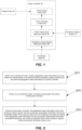
FIG. 1 is a structural block diagram of a dynamic control system for power of a vehicle according to the present invention; -
FIG. 2 is a flowchart of a dynamic control method for power of a vehicle according to the present invention; -
FIG. 3 is a schematic diagram of a power output curve when a vehicle according to the present invention is just started; -
FIG. 4 is a schematic diagram of a power output curve output at an uphill road segment by a power curve generation module of a dynamic control system for power of a vehicle according to the present invention; -
FIG. 5 is a schematic diagram of a power output curve output at a downhill road segment by a power curve generation module of a dynamic control system for power of a vehicle according to the present invention. - The technical solutions of the present invention are described in detail below with reference to the accompanying drawings and the embodiments.
- As shown in
FIG. 1 , in one aspect, a dynamic control system for power of a vehicle according to the present invention includes: - an electronic horizon system 10, configured to obtain geographic slope information of a road ahead of a vehicle based on an ADAS map and to send the geographic slope information to a
power controller 30; - an
accelerator pedal 20, configured to output accelerator pedal depth information to thepower controller 30; and - the
power controller 30, configured to receive the geographic slope information sent by the electronic horizon system 10 and the accelerator pedal depth information sent by theaccelerator pedal 20, to fit out a power output curve, with an accelerator pedal depth as an abscissa and an output torque of an engine/amotor 40 as an ordinate, for entering a next slope in the road ahead according to the geographic slope information and the accelerator pedal depth information and perform switching, and to control the engine/motor 40 of the vehicle to output the torque according to the power output curve. - Further, the
power controller 30 includes a power outputcurve generation module 301; and the power outputcurve generation module 301 includes: - a first key point obtaining unit, configured to obtain a first key point for fitting the power output curve, where the first key point is a point where the vehicle runs on a slope, and when the vehicle runs on the first key point, a same accelerator change depth as that on a flat road is capable of being used to obtain a same acceleration as that when running on the flat road;
- a second key point obtaining unit, configured to obtain a second key point for fitting the power output curve, where the second key point is a point for maximizing an accelerator pedal depth, or the second key point is a point for maximizing the output torque;
- a third key point obtaining unit, configured to obtain a third key point for fitting the power output curve, where the third key point is a point obtained according to a linear curve for flat-road running before the vehicle enters the slope;
- a fourth key point obtaining unit, configured to obtain a fourth key point for fitting the power output curve, where the fourth key point is a zero point (0, 0), that is, the accelerator pedal depth is 0, and the output torque is 0; and
- a fitting unit, configured to fit out the power output curve based on the first key point, the second key point, the third key point, and the fourth key point.
- In this embodiment, coordinates of the first key point are expressed as (A1 + D, T1 + ΔT + mgsin(i)), where T1 represents a torque, corresponding to an accelerator pedal depth A1, on the linear curve for flat-road running; ΔT represents a torque increment, corresponding to an accelerator pedal depth change intensity D, on the linear curve for flat-road running; i represents a front slope output by the electronic horizon system 10; m represents the mass of the vehicle; and g represents a gravitational acceleration.
- The
power controller 30 further includes an accelerator changeintensity generation module 302; and the accelerator changeintensity generation module 302 is configured to obtain the accelerator pedal depth change intensity D, and specifically includes: - a monotonic interval obtaining unit, configured to continuously acquire an accelerator pedal depth signal during flat-road running, to determine the monotonicity of the signal, and to extract continuous monotonically increasing or decreasing intervals;
- a monotonic interval filtering unit, configured to filter the monotonic intervals with the number of greater than a first preset value or smaller than a second preset value;
- an absolute value obtaining unit, configured to obtain an absolute value of a difference between a first value and a final value of each of the monotonic intervals, to serve as a primary accelerator pedal depth change intensity; and
- an average accelerator change intensity obtaining unit, configured to determine whether the number of accelerator pedal depth change intensities obtained by the absolute value obtaining unit is greater than a third preset value, where if the number of accelerator pedal depth change intensities obtained by the absolute value obtaining unit is greater than the third preset value, an average value is calculated.
- In this embodiment, if a front slope output by the electronic horizon system 10 is greater than 0, coordinates of the second key point are expressed as (1 - mgsin(i) / M, M); and if the front slope output by the electronic horizon system 10 is smaller than 0, the coordinates of the second key point are expressed as (1, M + mgsin(i)), where M represents a maximum torque that is capable of being output by the engine or the motor; i represents the front slope output by the electronic horizon system 10; m represents the mass of the vehicle; and g represents a gravitational acceleration.
- Further, the
power controller 30 further includes acurve switching module 303; and thecurve switching module 303 is configured to switch a linear curve for flat-road running to the power output curve. - The
power controller 30 further includes atorque output module 304; and thetorque output module 304 is configured to calculate a corresponding torque according to a current slope, a current accelerator pedal depth, and the power output curve, and to control the engine/motor 40 of the vehicle to output the torque. - As shown in
FIG. 2 , in another aspect, a dynamic control method for power of a vehicle according to the present invention includes: - S201: obtaining, by an electronic horizon system, geographic slope information of a road ahead of a vehicle based on an ADAS map and to send the geographic slope information to a power controller;
- S202: outputting, by an accelerator pedal, accelerator pedal depth information to the power controller; and
- S203: receiving, by the power controller, the geographic slope information sent by the electronic horizon system and the accelerator pedal depth information sent by the accelerator pedal, fitting out a power output curve for entering a next slope according to the geographic slope information and the accelerator pedal depth information and performing switching, and controlling an engine/a motor of the vehicle to output a torque according to the power output curve, where an abscissa of the power output curve is an accelerator pedal depth, and an ordinate of the power output curve is the torque output by the engine/motor.
- It should be noted that when the vehicle is just started, the power output curve of the vehicle is set as a default linear mode suitable for flat-road running. As shown in
FIG. 3 , if it is assumed that an output torque is T, an accelerator pedal depth is A, and a maximum torque that is capable of being output by the engine or the motor is M, a power output curve function (that is, the linear curve for flat-road running) is as follows:
- As shown in
FIG. 4 andFIG. 5 , in this embodiment, the step S203 specifically includes:
S2031: obtaining a front slope i from the electronic horizon system; and obtaining an accelerator pedal depth set as A1 before entering a slope. - S2032: obtaining a first key point, that is a
point ① as shown inFIG. 4 . The meaning of the first key point is that it is required to maintain the same driving performance as that on a flat road on the slope i, that is, an acceleration that can be obtained by the vehicle due to an accelerator pedal depth change on the slope is equal to an acceleration obtained by the same accelerator pedal depth change on the flat road. In this way, the driving experience and the driving stability can be ensured. - On the slope i, according to a flat road statistics habit, during acceleration of a driver, generally a vehicle accelerator change is set as D (an accelerator pedal depth change intensity), and a corresponding torque change is set as ΔT', so that an obtained acceleration is a' = ΔT' / m - gsin(i), where m is the mass of the vehicle, and g is a gravitational acceleration. It may be seen that when i > 0, that is, when the vehicle goes uphill, the acceleration under the same accelerator will decrease, while when i < 0, that is, when the vehicle goes downhill, the acceleration under the same accelerator will increase.
- On the flat road, a vehicle accelerator change is D, a corresponding torque change is ΔT, and an acceleration obtained by the vehicle is a' = ΔT / m.
- To make a = a', that is, ΔT' / m - gsin(i) = ΔT / m, ΔT' = ΔT + mgsin(i) may be obtained.
- It may be seen from the above that when the accelerator change increases by D relative to a current value, the torque change should be ΔT + mgsin(i), so that it can be ensured that the driver obtains the same driving experience as that on the flat road when running on the slope i. That is, on the basis of obtaining an increment value ΔT corresponding to the accelerator change D in an original power curve (i.e., a linear curve for flat-road running, and the linear curve is a default curve), a force of mgsin(i) needs to be superimposed.
- Therefore, coordinates (A1 + D, T1 + ΔT + mgsin(i)) of the first key point of the power output curve are obtained, where T1 represents a torque, corresponding to an accelerator pedal depth A1, on the original power curve, and ΔT is a torque increment, corresponding to the vehicle accelerator change D, on the original power curve
- S2033: obtaining a second key point, that is a
point ② as shown inFIG. 4 . When the accelerator change after the first key point continues increasing, a linear change about the same as a slope of a flat-road mode should be maintained, so that the same driving experience as that in the flat-road mode can continue being maintained. The slope of the flat-road mode is M equal to a vertical axis divided by a horizontal axis, and (M - 0) / (1 - 0) = M, so that the second half of the power output curve is obtained as follows:
- When mgsin(i) <= 0, A = 1 is substituted into the formula (1) to calculate a corresponding vertical axis T value, and coordinates (1, M + mgsin(i)) of the second key point are obtained; or otherwise, T = M is substituted into the formula (1) to calculate a corresponding horizontal axis A value, and coordinates (1 - mgsin(i) / M, M) of the second key point are obtained.
- S2034: obtaining a third key point, that is a
point ③ as shown inFIG. 4 . The third key point is the accelerator pedal depth and the torque (A1, T1) on the original power curve before entering the slope. - S2035: obtaining a fourth key point, that is a
point ④ as shown inFIG. 4 . The fourth key point is (0, 0), that is, when the accelerator pedal depth is maintained to be 0, the output torque is 0. - S2036: fitting out the power output curve based on the first key point, the second key point, the third key point, and the fourth key point by third-order curve fitting or other curve fitting manners.
-
FIG. 4 is an example of a real-time power output curve for going uphill (the slope i > 0). It may be seen that when the power output curve is switched, the vehicle runs on the third key point, without suddenly changing the power situation and affecting the driving smoothness. When the driver steps on the accelerator to obtain the acceleration, and the high-probability habitual accelerator change point D is reached, the acceleration obtained when going uphill is the same as that on the flat road, which facilitates the driver to maintain a consistent driving feeling, avoids the problem of excessive fuel consumption of transmission downshift possibly due to insufficient acceleration at the habitual accelerator depth on the flat road, and objectively has certain economical efficiency. -
FIG. 5 is an example of a real-time power output curve for going downhill (the slope i < 0). It may be seen that when the power output curve is switched, the vehicle runs on the third key point, without suddenly changing the power situation and affecting the driving smoothness. When the driver steps on the accelerator to obtain the acceleration, and the high-probability habitual accelerator change point D is reached, the acceleration obtained when going downhill is the same as that on the flat road, and the output torque is reduced, so that the fuel consumption is reduced under the condition of maintaining the consistent driving feeling. Meanwhile, when the accelerator is stepped on to the maximum, the acceleration obtained is the same, but the maximum torque will not be output, thereby ensuring the economical efficiency. - In this embodiment, a method for obtaining an average accelerator pedal depth change intensity D of the vehicle includes:
Step one: continuously acquiring an accelerator pedal depth signal during flat-road running from the electronic horizon system, determining the monotonicity of the signal, and extracting continuous monotonically increasing or decreasing intervals. - Step two: filtering too short and too long monotonic intervals (two ends of each of the intervals may be set to be a first preset value and a second preset value), to eliminate the volatility and slow trend effects of human operation.
- Step three: obtaining an absolute value of a difference between a first value and a final value of each of the monotonic intervals, to serve as a primary accelerator pedal depth change intensity.
- Step four: when the number of extracted accelerator change intensities reaches a lower limit K (i.e., a third preset value, and K is not less than 100), calculating the average accelerator pedal depth change intensity D, where D represents an average acceleration or deceleration habit of the driver on the flat road.
- The above are only the preferred embodiments of the present invention and are not intended to limit the present invention in any form. Although the present invention has been disclosed with the preferred embodiments as above, the preferred embodiments are not intended to limit the present invention. Any of those skilled in the art may make many possible changes and modifications to the technical solutions of the present invention by using the technical content disclosed above, or modify them to equivalent embodiments without departing from the scope of the technical solutions of the present invention. Therefore, any simple amendments, equivalent changes and modifications made to the above embodiments according to the technical essence of the present invention without departing from the content of the technical solutions of the present invention fall within the scope of protection of the technical solutions of the present invention.
- In a dynamic control system and method for power of a vehicle according to the present invention, geographic slope information of a road ahead is obtained by using an electronic horizon system, a power output curve for a next road segment is generated in real time according to the geographic slope information of the electronic horizon system and accelerator pedal depth information of a vehicle, and an engine/a motor of the vehicle is controlled to output a torque according to the power output curve; and such a method for obtaining the most suitable power output curve before entering a next slope through dynamic calculation to implement dynamic control of the power of the vehicle can ensure smooth driving of a driver, facilitate the energy consumption economy of the vehicle, and make the vehicle more adaptive to different terrains. The electronic horizon system is a database system that may provide the vehicle with accurate real-time information of the road ahead, and the geographic slope information of the road ahead can be accurately obtained by the electronic horizon system; and the present invention is convenient to implement in industry with the aid of the electronic horizon system and a vehicle-mounted device, and various components such as a power controller and an accelerator pedal are also convenient to process in industry.
Claims (10)
- A dynamic control system for power of a vehicle, characterized by comprising:an electronic horizon system, configured to obtain geographic slope information of a road ahead of a vehicle based on an advanced driver assistance system (ADAS) map and to send the geographic slope information to a power controller;an accelerator pedal, configured to output accelerator pedal depth information to the power controller; andthe power controller, configured to receive the geographic slope information sent by the electronic horizon system and the accelerator pedal depth information sent by the accelerator pedal, to fit out a power output curve, with an accelerator pedal depth as an abscissa and an output torque as an ordinate, for entering a next slope in the road ahead according to the geographic slope information and the accelerator pedal depth information and perform switching, and to control an engine/a motor of the vehicle to output the torque according to the power output curve.
- The dynamic control system for power of a vehicle according to claim 1, characterized in that the power controller comprises a power output curve generation module; and the power output curve generation module comprises:a first key point obtaining unit, configured to obtain a first key point for fitting the power output curve, where the first key point is a point where the vehicle runs on a slope, and when the vehicle runs on the first key point, a same accelerator change depth as that on a flat road is capable of being used to obtain a same acceleration as that when running on the flat road;a second key point obtaining unit, configured to obtain a second key point for fitting the power output curve, wherein the second key point is a point for maximizing an accelerator pedal depth, or the second key point is a point for maximizing the output torque;a third key point obtaining unit, configured to obtain a third key point for fitting the power output curve, where the third key point is a point obtained according to a linear curve for flat-road running before the vehicle enters the slope;a fourth key point obtaining unit, configured to obtain a fourth key point for fitting the power output curve, wherein the fourth key point is a zero point (0, 0), that is, the accelerator pedal depth is 0, and the output torque is 0; anda fitting unit, configured to fit out the power output curve based on the first key point, the second key point, the third key point, and the fourth key point.
- The dynamic control system for power of a vehicle according to claim 2, characterized in that coordinates of the first key point are expressed as (A1 + D, T1 + ΔT + mgsin(i)), wherein T1 represents a torque, corresponding to an accelerator pedal depth A1, on the linear curve for flat-road running; ΔT represents a torque increment, corresponding to an accelerator pedal depth change intensity D, on the linear curve for flat-road running; i represents a front slope output by the electronic horizon system; m represents the mass of the vehicle; and g represents a gravitational acceleration.
- The dynamic control system for power of a vehicle according to claim 3, characterized in that the power controller further comprises an accelerator change intensity generation module; and the accelerator change intensity generation module is configured to obtain the accelerator pedal depth change intensity D, and specifically comprises:a monotonic interval obtaining unit, configured to continuously acquire an accelerator pedal depth signal during flat-road running, to determine the monotonicity of the signal, and to extract continuous monotonically increasing or decreasing intervals;a monotonic interval filtering unit, configured to filter the monotonic intervals with the number of greater than a first preset value or smaller than a second preset value;an absolute value obtaining unit, configured to obtain an absolute value of a difference between a first value and a final value of each of the monotonic intervals, to serve as a primary accelerator pedal depth change intensity; andan average accelerator change intensity obtaining unit, configured to determine whether the number of accelerator pedal depth change intensities obtained by the absolute value obtaining unit is greater than a third preset value, wherein if the number of accelerator pedal depth change intensities obtained by the absolute value obtaining unit is greater than the third preset value, an average value is calculated.
- The dynamic control system for power of a vehicle according to claim 2, characterized in that if a front slope output by the electronic horizon system is greater than 0, coordinates of the second key point are expressed as (1 - mgsin(i) / M, M); and if a front slope output by the electronic horizon system is smaller than 0, coordinates of the second key point are expressed as (1, M + mgsin(i)), wherein M represents a maximum torque that is capable of being output by the engine or the motor; i represents the front slope output by the electronic horizon system; m represents the mass of the vehicle; and g represents a gravitational acceleration.
- The dynamic control system for power of a vehicle according to claim 1, characterized in that the power controller further comprises a curve switching module; and the curve switching module is configured to switch a linear curve for flat-road running to the power output curve.
- The dynamic control system for power of a vehicle according to claim 1, characterized in that the power controller further comprises a torque output module; and the torque output module is configured to calculate a corresponding torque according to a current slope, a current accelerator pedal depth, and the power output curve, and to control the engine/motor of the vehicle to output the torque.
- A dynamic control method for power of a vehicle, characterized by comprising:obtaining, by an electronic horizon system, geographic slope information of a road ahead of a vehicle based on an ADAS map, and sending the geographic slope information to a power controller;outputting, by an accelerator pedal, accelerator pedal depth information to the power controller;receiving, by the power controller, the geographic slope information sent by the electronic horizon system and the accelerator pedal depth information sent by the accelerator pedal, fitting out a power output curve for entering a next slope according to the geographic slope information and the accelerator pedal depth information and performing switching, and controlling an engine/a motor of the vehicle to output a torque according to the power output curve, wherein an abscissa of the power output curve is an accelerator pedal depth, and an ordinate of the power output curve is the torque output by the engine/motor.
- The dynamic control method for power of a vehicle according to claim 8, characterized in that the fitting out a power output curve for entering a next slope according to the geographic slope information and the accelerator pedal depth information comprises:obtaining a first key point for fitting the power output curve, where the first key point is a point where the vehicle runs on a slope, and when the vehicle runs on the first key point, a same accelerator change depth as that on a flat road is capable of being used to obtain a same acceleration as that when running on the flat road;obtaining a second key point for fitting the power output curve, wherein the second key point is a point for maximizing the accelerator pedal depth, or the second key point is a point for maximizing the output torque;obtaining a third key point for fitting the power output curve, where the third key point is a point obtained according to a linear curve for flat-road running before the vehicle enters the slope;obtaining a fourth key point for fitting the power output curve, wherein the fourth key point is a zero point (0, 0), that is, the accelerator pedal depth is 0, and the output torque is 0; andfitting out the power output curve based on the first key point, the second key point, the third key point, and the fourth key point.
- The dynamic control method for power of a vehicle according to claim 9, characterized in that coordinates of the first key point are expressed as (A1 + D, T1 + ΔT + mgsin(i)), wherein T1 represents a torque, corresponding to an accelerator pedal depth A1, on the linear curve for flat-road running; ΔT represents a torque increment, corresponding to an accelerator pedal depth change intensity D, on the linear curve for flat-road running; i represents a front slope output by the electronic horizon system; m represents the mass of the vehicle; and g represents a gravitational acceleration;
if a front slope output by the electronic horizon system is greater than 0, coordinates of the second key point are expressed as (1 - mgsin(i) / M, M); and if a front slope output by the electronic horizon system is smaller than 0, coordinates of the second key point are expressed as (1, M + mgsin(i)), where M represents a maximum torque that is capable of being output by the engine or the motor.
Applications Claiming Priority (2)
| Application Number | Priority Date | Filing Date | Title |
|---|---|---|---|
| CN202011140952.5A CN114379376B (en) | 2020-10-22 | 2020-10-22 | Vehicle dynamic control system and method |
| PCT/CN2021/109236 WO2022083208A1 (en) | 2020-10-22 | 2021-07-29 | Vehicle power dynamic control system and method |
Publications (2)
| Publication Number | Publication Date |
|---|---|
| EP4242083A1 true EP4242083A1 (en) | 2023-09-13 |
| EP4242083A4 EP4242083A4 (en) | 2024-12-18 |
Family
ID=81194775
Family Applications (1)
| Application Number | Title | Priority Date | Filing Date |
|---|---|---|---|
| EP21881628.8A Pending EP4242083A4 (en) | 2020-10-22 | 2021-07-29 | SYSTEM AND METHOD FOR DYNAMIC VEHICLE POWER CONTROL |
Country Status (4)
| Country | Link |
|---|---|
| US (1) | US12441293B2 (en) |
| EP (1) | EP4242083A4 (en) |
| CN (1) | CN114379376B (en) |
| WO (1) | WO2022083208A1 (en) |
Families Citing this family (5)
| Publication number | Priority date | Publication date | Assignee | Title |
|---|---|---|---|---|
| CN114872706A (en) * | 2022-05-06 | 2022-08-09 | 恒大恒驰新能源汽车研究院(上海)有限公司 | A vehicle control method, device, electronic device and storage medium |
| CN115031748A (en) * | 2022-05-26 | 2022-09-09 | 芜湖宏景电子股份有限公司 | Automobile oil quantity indicating system based on automatic navigation |
| JP2025523637A (en) * | 2022-06-30 | 2025-07-23 | 深▲ジェン▼引望智能技術有限公司 | Acceleration compensation method and device, and vehicle |
| CN115246382B (en) * | 2022-09-21 | 2022-12-13 | 清研军融通用装备(苏州)有限公司 | Control method for speed of hybrid electric vehicle |
| DE102024132590A1 (en) | 2024-11-08 | 2026-05-13 | Dr. Ing. H.C. F. Porsche Aktiengesellschaft | Computer-implemented method for operating at least one vehicle |
Family Cites Families (27)
| Publication number | Priority date | Publication date | Assignee | Title |
|---|---|---|---|---|
| DE10210795B4 (en) * | 2002-03-12 | 2020-03-19 | Volkswagen Ag | Driving behavior switchover |
| JP3906717B2 (en) * | 2002-03-19 | 2007-04-18 | トヨタ自動車株式会社 | Accelerator opening setting device and vehicle equipped with the same |
| JP2004204832A (en) * | 2002-11-05 | 2004-07-22 | Nissan Motor Co Ltd | Vehicle driving force control device |
| JP4239725B2 (en) * | 2003-07-30 | 2009-03-18 | トヨタ自動車株式会社 | Vehicle and vehicle control method |
| JP2005333729A (en) * | 2004-05-20 | 2005-12-02 | Moric Co Ltd | Drive controller for electric vehicle |
| JP4539267B2 (en) | 2004-09-28 | 2010-09-08 | アイシン精機株式会社 | Shift control device for automatic transmission |
| US9457811B2 (en) * | 2009-09-17 | 2016-10-04 | Ford Global Technologies, Llc | Brake assisted vehicle engine restart on a road grade |
| JP5743134B2 (en) | 2010-11-26 | 2015-07-01 | Udトラックス株式会社 | Auxiliary braking device for vehicle |
| KR101230903B1 (en) * | 2010-12-08 | 2013-02-07 | 현대자동차주식회사 | Control method for creep torque of electric vehicle |
| JP5417386B2 (en) * | 2011-07-01 | 2014-02-12 | 日立オートモティブシステムズ株式会社 | Vehicle motion control device |
| US8935080B2 (en) * | 2012-01-26 | 2015-01-13 | Ford Global Technologies, Llc | Engine response adjustment |
| DE102012222482B4 (en) | 2012-12-06 | 2025-04-30 | Bayerische Motoren Werke Aktiengesellschaft | Method and device for improved switching between accelerator pedal characteristics |
| CA2836450A1 (en) * | 2013-12-16 | 2015-06-16 | Thomson Power, Inc. | Electric vehicle power management driver control system |
| CN104494599B (en) * | 2014-01-30 | 2015-11-25 | 比亚迪股份有限公司 | Vehicle and slide back-feed control method |
| US9428193B2 (en) * | 2014-05-21 | 2016-08-30 | Ford Global Technologies, Llc | Method for preventing wheel spin on stopped vehicles |
| CN104071152A (en) * | 2014-07-04 | 2014-10-01 | 上汽通用五菱汽车股份有限公司 | Compensation method for finished automobile power adjustment utilizing gradient sensor |
| CN106467103B (en) * | 2015-08-13 | 2019-11-05 | 厦门雅迅网络股份有限公司 | A kind of the Intelligent oil-saving control method and system of vehicle |
| KR101713734B1 (en) * | 2015-10-06 | 2017-03-08 | 현대자동차 주식회사 | Method and apparatus of controlling hybrid electric vehicle |
| US9707963B2 (en) * | 2015-10-08 | 2017-07-18 | Ford Global Technologies, Llc | Systems and methods for operating a vehicle with a manual shift transmission |
| CN106427664A (en) * | 2016-09-30 | 2017-02-22 | 上汽通用五菱汽车股份有限公司 | Torque control method and system for electric vehicle |
| CN107150687B (en) * | 2017-04-27 | 2019-08-13 | 广州汽车集团股份有限公司 | The transmitted in both directions control system of vehicle |
| CN109572676B (en) * | 2017-09-29 | 2020-07-10 | 比亚迪股份有限公司 | Hybrid electric vehicle and power utilization control method and device thereof |
| CN107762640B (en) * | 2017-10-12 | 2019-12-06 | 潍柴动力股份有限公司 | Intelligent accelerator control method |
| FR3075735B1 (en) | 2017-12-21 | 2019-11-15 | Renault S.A.S | METHOD FOR DETERMINING THE TORQUE SETTING OF A MOTOR VEHICLE ENGINE |
| CN110154784B (en) * | 2019-06-02 | 2020-05-19 | 吉林大学 | Driver demand driving torque online determination method |
| CN111645666B (en) | 2019-09-20 | 2021-07-23 | 长城汽车股份有限公司 | Engine torque control method and control device |
| US11440417B2 (en) * | 2020-02-19 | 2022-09-13 | Dana Automotive Systems Group, Llc | System and method for adjusting vehicle performance |
-
2020
- 2020-10-22 CN CN202011140952.5A patent/CN114379376B/en active Active
-
2021
- 2021-07-29 US US18/250,285 patent/US12441293B2/en active Active
- 2021-07-29 WO PCT/CN2021/109236 patent/WO2022083208A1/en not_active Ceased
- 2021-07-29 EP EP21881628.8A patent/EP4242083A4/en active Pending
Also Published As
| Publication number | Publication date |
|---|---|
| US12441293B2 (en) | 2025-10-14 |
| CN114379376B (en) | 2025-04-22 |
| WO2022083208A1 (en) | 2022-04-28 |
| EP4242083A4 (en) | 2024-12-18 |
| US20240017712A1 (en) | 2024-01-18 |
| CN114379376A (en) | 2022-04-22 |
Similar Documents
| Publication | Publication Date | Title |
|---|---|---|
| US12441293B2 (en) | Dynamic control system and method for power of vehicle | |
| Ma et al. | An eco-drive experiment on rolling terrains for fuel consumption optimization with connected automated vehicles | |
| CN101280729B (en) | Energy-saving running promoting system and method | |
| US11107002B2 (en) | Reinforcement learning based ground vehicle control techniques | |
| RU2640919C2 (en) | Method and system for optimisation of energy consumption in vehicle | |
| CN108001453B (en) | Method and system for identifying high-energy-consumption driving behaviors | |
| CN114144329B (en) | Motor torque filtering control method and system and hybrid vehicle | |
| RU2479446C2 (en) | Defining acceleration characteristics | |
| CN109723813A (en) | A kind of target gear calculation method and device | |
| WO2013189664A1 (en) | Method and device for traveling a route with a specified desired average energy consumption | |
| KR20180104872A (en) | Transmission apparatus and method for cruise control system responsive to driving condition | |
| CN115179940A (en) | Mining vehicle constant-speed cruising method and device, vehicle and storage medium | |
| CN115009277A (en) | Downhill control method and system for automobile adaptive cruise system | |
| CN108116243B (en) | Method, device and vehicle for adjusting electric balance point of hybrid electric vehicle | |
| CN109291933B (en) | Method and system for improving endurance mileage of electric vehicle | |
| US20100152956A1 (en) | Method and device for outputting driving information indicating an acceleration option that is optimal in terms of power consumption in a motor vehicle | |
| CN114074660A (en) | A kind of predictive cruise fuel-saving control method, device and storage medium | |
| CN113859252A (en) | Vehicle weight determining method and device | |
| CN107139723A (en) | The method and apparatus for controlling the travel speed of vehicle | |
| CN116534039A (en) | Vehicle control method and device, vehicle and medium | |
| CN106740821B (en) | A kind of control method and system of hybrid power new-energy automobile | |
| CN115257756B (en) | A method and device for controlling vehicle lane change based on optimal fuel consumption | |
| US11982346B2 (en) | Terrain based dynamic gear shift control method and system for vehicle | |
| CN118289001A (en) | Accelerator pedal pre-control method, system, device and medium under plain conditions | |
| CN112406560B (en) | Method and device for adjusting generated power of range extender, storage medium and vehicle |
Legal Events
| Date | Code | Title | Description |
|---|---|---|---|
| STAA | Information on the status of an ep patent application or granted ep patent |
Free format text: STATUS: THE INTERNATIONAL PUBLICATION HAS BEEN MADE |
|
| PUAI | Public reference made under article 153(3) epc to a published international application that has entered the european phase |
Free format text: ORIGINAL CODE: 0009012 |
|
| STAA | Information on the status of an ep patent application or granted ep patent |
Free format text: STATUS: REQUEST FOR EXAMINATION WAS MADE |
|
| 17P | Request for examination filed |
Effective date: 20230331 |
|
| AK | Designated contracting states |
Kind code of ref document: A1 Designated state(s): AL AT BE BG CH CY CZ DE DK EE ES FI FR GB GR HR HU IE IS IT LI LT LU LV MC MK MT NL NO PL PT RO RS SE SI SK SM TR |
|
| DAV | Request for validation of the european patent (deleted) | ||
| DAX | Request for extension of the european patent (deleted) | ||
| RAP3 | Party data changed (applicant data changed or rights of an application transferred) |
Owner name: XIAMEN YAXON ZHILIAN TECHNOLOGY CO., LTD. |
|
| A4 | Supplementary search report drawn up and despatched |
Effective date: 20241114 |
|
| RIC1 | Information provided on ipc code assigned before grant |
Ipc: B60L 15/20 20060101ALI20241108BHEP Ipc: B60W 30/14 20060101ALI20241108BHEP Ipc: B60W 30/188 20120101AFI20241108BHEP |
|
| STAA | Information on the status of an ep patent application or granted ep patent |
Free format text: STATUS: EXAMINATION IS IN PROGRESS |
|
| 17Q | First examination report despatched |
Effective date: 20250723 |
|
| GRAP | Despatch of communication of intention to grant a patent |
Free format text: ORIGINAL CODE: EPIDOSNIGR1 |
|
| STAA | Information on the status of an ep patent application or granted ep patent |
Free format text: STATUS: GRANT OF PATENT IS INTENDED |
|
| INTG | Intention to grant announced |
Effective date: 20260407 |