EP4242077A1 - Monitoring of landing gear servo valve assembly - Google Patents
Monitoring of landing gear servo valve assembly Download PDFInfo
- Publication number
- EP4242077A1 EP4242077A1 EP23161045.2A EP23161045A EP4242077A1 EP 4242077 A1 EP4242077 A1 EP 4242077A1 EP 23161045 A EP23161045 A EP 23161045A EP 4242077 A1 EP4242077 A1 EP 4242077A1
- Authority
- EP
- European Patent Office
- Prior art keywords
- pressure
- control unit
- brake control
- determining
- conduit
- Prior art date
- Legal status (The legal status is an assumption and is not a legal conclusion. Google has not performed a legal analysis and makes no representation as to the accuracy of the status listed.)
- Granted
Links
Images





Classifications
-
- B—PERFORMING OPERATIONS; TRANSPORTING
- B60—VEHICLES IN GENERAL
- B60T—VEHICLE BRAKE CONTROL SYSTEMS OR PARTS THEREOF; BRAKE CONTROL SYSTEMS OR PARTS THEREOF, IN GENERAL; ARRANGEMENT OF BRAKING ELEMENTS ON VEHICLES IN GENERAL; PORTABLE DEVICES FOR PREVENTING UNWANTED MOVEMENT OF VEHICLES; VEHICLE MODIFICATIONS TO FACILITATE COOLING OF BRAKES
- B60T8/00—Arrangements for adjusting wheel-braking force to meet varying vehicular or ground-surface conditions, e.g. limiting or varying distribution of braking force
- B60T8/17—Using electrical or electronic regulation means to control braking
- B60T8/1701—Braking or traction control means specially adapted for particular types of vehicles
- B60T8/1703—Braking or traction control means specially adapted for particular types of vehicles for aircrafts
-
- B—PERFORMING OPERATIONS; TRANSPORTING
- B60—VEHICLES IN GENERAL
- B60T—VEHICLE BRAKE CONTROL SYSTEMS OR PARTS THEREOF; BRAKE CONTROL SYSTEMS OR PARTS THEREOF, IN GENERAL; ARRANGEMENT OF BRAKING ELEMENTS ON VEHICLES IN GENERAL; PORTABLE DEVICES FOR PREVENTING UNWANTED MOVEMENT OF VEHICLES; VEHICLE MODIFICATIONS TO FACILITATE COOLING OF BRAKES
- B60T17/00—Component parts, details, or accessories of power brake systems not covered by groups B60T8/00, B60T13/00 or B60T15/00, or presenting other characteristic features
- B60T17/18—Safety devices; Monitoring
- B60T17/22—Devices for monitoring or checking brake systems; Signal devices
- B60T17/221—Procedure or apparatus for checking or keeping in a correct functioning condition of brake systems
-
- B—PERFORMING OPERATIONS; TRANSPORTING
- B64—AIRCRAFT; AVIATION; COSMONAUTICS
- B64C—AEROPLANES; HELICOPTERS
- B64C25/00—Alighting gear
- B64C25/32—Alighting gear characterised by elements which contact the ground or similar surface
- B64C25/42—Arrangement or adaptation of brakes
Definitions
- the present disclosure relates to valves and, in particular, to systems and methods for monitoring a health of a landing gear servo valve.
- Aircraft typically include a braking system operatively coupled to the wheels of the aircraft and configured to slow the wheels, and the aircraft, during, for example, landing or a rejected takeoff.
- Brake systems typically employ a series of friction disks located about an axle. The friction disks may be compressed together to stop the aircraft. The compression of the friction disks may be controlled by one or more hydraulic actuator(s). Hydraulic fluid is typically provided to the hydraulic actuators via flexible hosing or tubing that is connected to a hydraulic fluid source located proximate the aircraft fuselage or wing.
- a servo valve controls the flow of the hydraulic fluid to and from the brake actuators. Wear of the servo valve can lead to performance degradation and/or improper function of the brake system.
- a system for monitoring an electrohydraulic servo valve is disclosed herein.
- the system may comprise a brake control unit, a valve monitoring sensor configured to measure at least one of a pressure or a fluid flow rate in a conduit fluidly connected to a control port of the electrohydraulic servo valve, and a tangible, non-transitory memory configured to communicate with the brake control unit.
- the tangible, non-transitory memory has instructions stored thereon that, in response to execution by the brake control unit, cause the brake control unit to perform operations, which may comprise receiving, by the brake control unit, a brake command; outputting, by the brake control unit, a pressure signal to the electrohydraulic servo valve based on the brake command; receiving, by the brake control unit, a sensor signal from the valve monitoring sensor; and determining, by the brake control unit, a health of the electrohydraulic servo valve based on the sensor signal.
- determining, by the brake control unit, the health of the electrohydraulic servo valve based on the sensor signal may comprise determining, by the brake control unit, an upper pressure threshold based on a current of the pressure signal; determining, by the brake control unit, a lower pressure threshold based on the current of the pressure signal; determining, by the brake control unit, the pressure in the conduit based on the sensor signal; and comparing, by the brake control unit, the pressure in the conduit to the upper pressure threshold and the lower pressure threshold.
- the operations may further comprise commanding, by the brake control unit, a display to output an alert in response to at least one of determining, by the brake control unit, the pressure in the conduit is greater than the upper pressure threshold; or determining, by the brake control unit, the pressure in the conduit is less than the lower pressure threshold.
- the operations may further comprise determining, by the brake control unit, a first difference between the pressure in the conduit and the upper pressure threshold; determining by the brake control unit, a second difference between the pressure in the conduit and the lower pressure threshold; and comparing, by the brake control unit, each of the first difference and the second different to a difference threshold.
- the operations may further comprise commanding, by the brake control unit, a display to output a warning alert, in response to at least one of the first difference or the second difference being less than the difference threshold.
- determining, by the brake control unit, the upper pressure threshold based on the current of the pressure signal may comprise determining, by the brake control unit, an expected pressure of the conduit based on the current of the pressure signal; and adding, by the brake control unit, a first value to the expected pressure.
- determining, by the brake control unit, the upper pressure threshold based on the current of the pressure signal may comprise locating, by the brake control unit, a point on an upper threshold line corresponding the current of the pressure signal.
- the upper threshold line may be a linear line having a constant slope.
- a method for monitoring an electrohydraulic servo valve of an aircraft landing gear is also disclosed herein.
- the method may comprise the steps of receiving, by a brake control unit, a brake command; outputting, by the brake control unit, a pressure signal to the electrohydraulic servo valve based on the brake command; receiving, by the brake control unit, a sensor signal from a valve monitoring sensor; and determining, by the brake control unit, a health of the electrohydraulic servo valve based on the sensor signal.
- the valve monitoring sensor may be configured to measure at least one of a pressure or a fluid flow rate in a conduit fluidly coupled to a control port of the electrohydraulic servo valve
- determining, by the brake control unit, the health of the electrohydraulic servo valve based on the sensor signal may comprise determining, by the brake control unit, an upper pressure threshold based on a current of the pressure signal; determining, by the brake control unit, a lower pressure threshold based on the current of the pressure signal; determining, by the brake control unit, the pressure in the conduit based on the sensor signal; and comparing, by the brake control unit, the pressure in the conduit to the upper pressure threshold and to the lower pressure threshold.
- the method may further comprise commanding, by the brake control unit, a display to output an alert in response to at least one of determining, by the brake control unit, the pressure in the conduit is greater than the upper pressure threshold; or determining, by the brake control unit, the pressure in the conduit is less than the lower pressure threshold.
- comparing, by the brake control unit, the pressure in the conduit to the upper pressure threshold and to the lower pressure threshold may comprise determining, by the brake control unit, a first difference between the pressure in the conduit and the upper pressure threshold; determining by the brake control unit, a second difference between the pressure in the conduit and the lower pressure threshold; and comparing, by the brake control unit, each of the first difference and the second different to a difference threshold.
- the method may further comprise commanding, by the brake control unit, the display to output a warning alert, in response to at least one of the first difference or the second difference being less than the difference threshold.
- determining, by the brake control unit, the upper pressure threshold based on the current of the pressure signal may comprise determining, by the brake control unit, an expected pressure of the conduit based on the current of the pressure signal; and adding, by the brake control unit, a first value to the expected pressure.
- determining, by the brake control unit, the upper pressure threshold based on the current of the pressure signal may comprise locating, by the brake control unit, a point on an upper threshold line corresponding the current of the pressure signal.
- the upper threshold line may be a linear line having a constant slope.
- determining, by the brake control unit, the lower pressure threshold based on the current of the pressure signal may comprise locating, by the brake control unit, a point on a lower threshold line corresponding the current of the pressure signal.
- the lower threshold line may be parallel to the upper threshold line.
- the landing gear may comprise a brake assembly including a brake stack and an actuator configured to apply pressure to the brake stack, an electrohydraulic servo valve configured to control a flow of fluid to the brake assembly, a conduit fluidly connecting a control port of the electrohydraulic servo valve and an inlet of the actuator, a valve monitoring sensor configured to measure at least one of a pressure or a fluid flow rate in the conduit, and a brake control unit in communication with the electrohydraulic servo valve and the valve monitoring sensor.
- the brake control unit may be configured to output a pressure signal to the electrohydraulic servo valve and to receive a sensor signal from the valve monitoring sensor.
- the brake control unit may be configured to determine a health of the electrohydraulic servo valve based on the sensor signal and the pressure signal.
- the brake control unit may determine the health of the electrohydraulic servo valve by determining an upper pressure threshold and a lower pressure threshold based on a current of the pressure signal, determining the pressure in the conduit based on the sensor signal, and comparing the pressure in the conduit to the upper pressure threshold and the lower pressure threshold.
- the brake control unit may be configured to determine a first difference between the pressure in the conduit and the upper pressure threshold and a second difference between the pressure in the conduit and the lower pressure threshold.
- the brake control unit may be configured to command a display to output a first alert in response to determining at least one of the pressure in the conduit is greater than the upper pressure threshold or the pressure in the conduit is less than the lower pressure threshold.
- the brake control unit may be configured to command the display to output a second alert, different from the first alert, in response to determining at least one of the pressure in the conduit is less than or equal to the upper pressure threshold and the first difference is less than a difference threshold, or the pressure in the conduit is greater than or equal to the lower pressure threshold and the second difference is less than the difference threshold.
- any reference to singular includes plural embodiments, and any reference to more than one component or step may include a singular embodiment or step.
- Aircraft 10 includes landing gear such as left landing gear 12, right landing gear 14, and nose landing gear 16.
- Left landing gear 12, right landing gear 14, and nose landing gear 16 may generally support aircraft 10 when aircraft 10 is not flying, allowing aircraft 10 to taxi, take off, and land without damage.
- Left landing gear 12 may include left outboard (LOB) wheel 13A and left inboard (LIB) wheel 13B coupled by an axle 20.
- Right landing gear 14 may include right outboard (ROB) wheel 15A and right inboard (RIB) wheel 15B coupled by an axle 22.
- Nose landing gear 16 may include left nose wheel 17A and right nose wheel 17B coupled by an axle 24.
- the nose wheels may differ from the left and right landing gear wheels in that the nose wheels may not include a brake.
- Aircraft 10 may comprise a brake control unit (BCU) 30 and cockpit controls 32.
- BCU 30 may be located in the fuselage of the aircraft.
- Left landing gear 12 and right landing gear 14 may be in communication with BCU 30 and may receive commands from BCU 30.
- BCU 30 may send brake commands to left landing gear 12 and right landing gear 14 based on signals received from cockpit controls 32 (e.g., from a pilot or autobrake system), from sources external to the aircraft (e.g., from a ground controller), or from onboard sensors.
- brake system 100 may be configured to control braking of left landing gear 12 and right landing gear 14.
- Brake system 100 may include a LOB brake assembly 102 coupled to LOB wheel 13A, a LIB brake assembly 104 coupled to LIB wheel 13B, a ROB brake assembly 106 coupled to ROB wheel 15A, and a RIB brake assembly 108 coupled to RIB wheel 15B. While FIG.
- brake system 100 comprising two landing gears (i.e., left landing gear 12 and right landing gear 14) with four total wheels, it is further contemplated and understood that the systems and methods described herein may apply to brake systems comprising any number of landing gears and/or number of wheels per landing gear.
- Brake assemblies 102, 104, 106, 108 are configured to apply and release braking force on their respective wheels.
- Brake assemblies 102, 104, 106, 108 may each comprise an actuator (e.g., a piston assembly) configured to apply pressure to a brake stack of the brake assembly.
- LOB brake assembly 102 includes a LOB actuator 122 and a LOB brake stack 124
- LIB brake assembly 104 includes a LIB actuator 126 and a LIB brake stack 1208
- ROB brake assembly 106 includes a ROB actuator 130 and a ROB brake stack 132
- RIB brake assembly 108 includes a RIB actuator 134 and a RIB brake stack 136.
- Each of the brake actuators 122, 126, 130, 134 is configured to apply pressure to its respective brake stack, thereby decreasing a rotational speed of the wheel coupled to the brake and/or preventing rotation of the wheel.
- BCU 30 controls the pressure applied by brake actuators 122, 126, 130, 134 via an electrohydraulic servo valve (EHSV) fluidly coupled to each of the brake actuators.
- EHSV electrohydraulic servo valve
- a LOB EHSV 140 is operably coupled to BCU 30 and LOB actuator 122
- a LIB EHSV 160 is operably coupled to BCU 30 and LIB actuator 126
- a ROB EHSV 180 is operably coupled to BCU 30 and ROB actuator 130
- a RIB EHSV 200 is operably coupled to BCU 30 and RIB actuator 134.
- BCU 30 may include a general-purpose processor, a digital signal processor (DSP), an application specific integrated circuit (ASIC), a field programmable gate array (FPGA), or some other programmable logic device, discrete gate or transistor logic, discrete hardware components, or any combination thereof.
- a tangible, non-transitory computer-readable storage medium 110 may be in communication with BCU 30.
- the storage medium 110 may comprise any tangible, non-transitory computer-readable storage medium known in the art.
- the storage medium 110 has instructions stored thereon that, in response to execution by BCU 30, cause BCU 30 to perform operations related to monitoring a health of EHSVs 140, 160, 180, 200.
- non-transitory is to be understood to remove only propagating transitory signals per se from the claim scope and does not relinquish rights to all standard computer-readable media that are not only propagating transitory signals per se.
- LOB EHSV 140 receives LOB pressure signals 142 from BCU 30 and provides fluid 144 to LOB actuator 122.
- LOB EHSV 140 may be fluidly connected to and may receive fluid 144 from a fluid source 156.
- LOB EHSV 140 modulates the flow rate and/or pressure of the fluid 144 provided to LOB actuator 122 based on the LOB pressure signal 142 received from BCU 30.
- the pressure of the fluid 144 in the conduit (or fluid path) 146 connecting an outlet of LOB EHSV 140 and an inlet of LOB actuator 122 is proportional to the current of the LOB pressure signal 142 sent by BCU 30.
- the pressure applied by LOB actuator 122 to LOB brake stack 124 may be proportional to the current of LOB pressure signal 142.
- BCU 30 may increase or decrease a pressure applied to LOB brake stack 124 by increasing or decreasing, respectively, the current of LOB pressure signal 142.
- a LOB valve monitoring sensor 150 may be coupled to conduit 146.
- LOB valve monitoring sensor 150 is configured to measure a pressure and/or flow rate of the fluid 144 in conduit 146.
- LOB valve monitoring sensor 150 is located between the outlet of LOB EHSV 140 and the inlet of LOB actuator 122.
- LOB valve monitoring sensor 150 outputs a sensor signal 152 corresponding to the pressure and/or fluid flow rate in conduit 146 to BCU 30.
- BCU 30 receives sensor signal 152 from LOB valve monitoring sensor 150 and determines a pressure and/or a flow rate in conduit 146 based on the sensor signal 152.
- BCU 30 is configured to monitor a health of LOB EHSV 140 using sensor signal 152.
- LIB EHSV 160 receives LIB pressure signals 162 from BCU 30 and provides fluid 144 to LIB actuator 126.
- LOB EHSV 140 may be fluidly connected to and may receive fluid 144 from fluid source 156. While FIG. 2 shows LOB EHSV 140 and LIB EHSV 160 both receiving fluid from fluid source 156, in various embodiments, LOB EHSV 140 and LIB EHSV 160 may each have their own dedicated fluid source.
- LIB EHSV 160 modulates the flow rate and/or pressure of the fluid 144 provided to LIB actuator 126 based on a LIB pressure signal 162 received from BCU 30.
- the pressure of the fluid 144 in the conduit (or flow path) 166 connecting an outlet of LIB EHSV 160 and an inlet of LIB actuator 126 is proportional to the current of the LIB pressure signal 162 sent by BCU 30.
- the pressure applied by LIB actuator 126 to LIB brake stack 128 may be proportional to the current of LIB pressure signal 162.
- BCU 30 may increase or decrease a pressure applied to LIB brake stack 128 by increasing or decreasing, respectively, the current of LIB pressure signal 162.
- a LIB valve monitoring sensor 170 may be coupled to conduit 166.
- LIB valve monitoring sensor 170 is configured to measure a pressure and/or flow rate of the fluid 144 in conduit 166.
- LIB valve monitoring sensor 170 is located between the outlet of LIB EHSV 160 and the inlet of LIB actuator 126.
- LIB valve monitoring sensor 170 outputs a sensor signal 172 to BCU 30.
- Sensor signal 172 corresponds to (i.e., is indicative of) the pressure and/or fluid flow rate in conduit 166.
- BCU 30 receives sensor signal 172 from LIB valve monitoring sensor 170 and determines a pressure and/or a flow rate in conduit 166 based on the sensor signal 172.
- BCU 30 is configured to monitor a health of LIB EHSV 160 based on sensor signal 172.
- ROB EHSV 180 receives ROB pressure signals 182 from BCU 30 and provides a fluid 184 to ROB actuator 130.
- ROB EHSV 180 may be fluidly connected to and may receive fluid 184 from a fluid source 196.
- ROB EHSV 180 modulates the flow rate and/or pressure of the fluid 184 provided to ROB actuator 130 based on the ROB pressure signal 182 received from BCU 30.
- the pressure and/or flow rate of the fluid 184 in a conduit 186 (or flow path) connecting ROB EHSV 180 and ROB actuator 130 is proportional to the current of the ROB pressure signal 182 sent by BCU 30.
- the pressure applied by ROB actuator 130 to ROB brake stack 132 may be proportional to the current of ROB pressure signal 182.
- BCU 30 may increase or decrease a pressure applied to ROB brake stack 132 by increasing or decreasing, respectively, the current of ROB pressure signal 182.
- a ROB valve monitoring sensor 190 may be coupled to conduit 186.
- ROB valve monitoring sensor 190 is located between the outlet of ROB EHSV 180 and the inlet of ROB actuator 130.
- ROB valve monitoring sensor 190 is configured to measure a pressure and/or flow rate of the fluid 184 in conduit 186.
- ROB valve monitoring sensor 190 outputs a sensor signal 192 to BCU 30 corresponding to the pressure and/or fluid flow rate in conduit 186.
- BCU 30 receives sensor signal 192 from ROB valve monitoring sensor 190 and determines a pressure and/or a flow rate in conduit 186 based on the sensor signal 192.
- BCU 30 is configured to monitor a health of ROB EHSV 180 using sensor signal 192.
- RIB EHSV 200 receives RIB pressure signals 202 from BCU 30 and provides fluid 184 to RIB actuator 134.
- RIB EHSV 200 may be fluidly connected to and may receive fluid 184 from fluid source 196. While FIG. 2 shows ROB EHSV 180 and RIB EHSV 200 both receiving fluid 184 from fluid source 196, in various embodiments, ROB EHSV 180 and RIB EHSV 200 may each have their own dedicated fluid source.
- LOB EHSV 140, LIB EHSV 160, ROB EHSV 180, and RIB EHSV 200 may be fluidly connected to the same fluid source.
- RIB EHSV 200 is configured to modulate the flow rate and/or pressure of the fluid 184 provided to RIB actuator 134 based on the RIB pressure signal 202 received from BCU 30.
- the pressure and/or flow rate of the fluid 184 in the conduit (or flow path) 206 connecting RIB EHSV 200 and RIB actuator 134 is proportional to the current of the RIB pressure signal 202 sent by BCU 30.
- the pressure applied by RIB actuator 134 to RIB brake stack 136 may be proportional to the current of RIB pressure signal 202.
- BCU 30 may increase or decrease a pressure applied to RIB brake stack 136 by increasing or decreasing, respectively, the current of RIB pressure signal 202.
- a RIB valve monitoring sensor 210 may be coupled to conduit 206.
- RIB valve monitoring sensor 210 is located between the outlet of RIB EHSV 200 and the inlet of RIB actuator 134.
- RIB valve monitoring sensor 210 is configured to measure a pressure and/or flow rate of the fluid 184 in conduit 206.
- RIB valve monitoring sensor 210 outputs a sensor signal 212 to BCU 30 corresponding to the pressure and/or fluid flow rate in conduit 206.
- BCU 30 receives sensor signal 212 from RIB valve monitoring sensor 210 and determines a pressure and/or a flow rate in conduit 206 based on the sensor signal 212.
- BCU 30 is configured to monitor a health of RIB EHSV 200 using sensor signal 212.
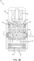
- RIB EHSV 200 includes a torque motor 220.
- Torque motor 220 includes an armature 222 and a coil 224.
- RIB EHSV 200 further includes a spool 230 and a sleeve 232.
- Sleeve 232 is configured to surround an outer circumferential surface 231 of spool 230.
- a diameter of spool 230 may be varied along outer circumferential surface 231.
- Outer circumferential surface 231 and sleeve 232 may define various flow paths about spool 230.
- sleeve 232 contacts portions of outer circumferential surface 231, thereby forming a sealing interface with the contacted portions of outer circumferential surface 231, and sleeve 232 is spaced apart from other portions of outer circumferential surface 231, thereby forming flow paths between the outer circumferential surface 231 of spool 230 and an inner circumferential surface 233 of sleeve 232.
- one or more fluid path may also be formed through an interior of spool 230.
- Spool 230 is configured to translate relative to and within sleeve 232.
- spool 230 may translate axially along axis A.
- Sleeve 232 may be located about axis A.
- a flapper 226 is attached to armature 222.
- coil 224 In response to receiving current in a first, or positive, direction (e.g., in response to a first pressure signal 202 ( FIG. 2 )), coil 224 generates a first magnetic field.
- the first magnetic field is configured to translate armature 222 in a first direction, thereby driving flapper 226 toward and/or into contact with a first nozzle 228 (as shown in FIG. 3B ).
- coil 224 In response to receiving current in a second, or negative, direction (e.g., in response to a second pressure signal 202 ( FIG. 2 )), coil 224 generates a second magnetic field in the opposite direction of the first magnetic field.
- the second magnetic field is configured to translate armature 222 in a second direction, thereby driving flapper 226 toward and/or into contact with a second nozzle 229 (as shown in FIG. 3C ).
- first pressure stage 234 may be defined, at least partially, by a first end 236 of spool 230.
- the increase in fluid pressure in first pressure stage 234 increases a pressure exerted on first end 236 of spool 230 and thereby forces spool 230 to translate in a first axial direction D1.
- FIG. 3C translation of flapper 226 into contact with second nozzle 129 increases the fluid pressure in within a second pressure stage 238 of RIB EHSV 200.
- Second pressure stage 238 may be defined, at least partially, by a second end 239 of spool 230.
- the increase in fluid pressure in second pressure stage 238 increases the pressure exerted on second end 239 of spool 230 and thereby forces spool 230 to translate in a second axial direction D2.
- the axial direction of translation of spool 230 may be controlled by applying current in either the first direction (e.g., positive current) or in the second direction (e.g., negative current) to coil 224.
- RIB EHSV 200 includes a supply port 240.
- fluid 184 ( FIG. 2 ) from fluid source 196 ( FIG. 2 ) may be received at supply port 240.
- the fluid 184 from fluid source 196 flows into RIB EHSV 200 via supply port 240.
- a filter assembly 246 may be fluidly coupled to supply port 240 such that fluid flows into filter assembly 246 upon entering RIB EHSV 200 via supply port 240.
- Filter assembly 246 may define multiple orifices and flow paths configured to fluidly connect supply port 240 to various components of RIB EHSV 200.
- RIB EHSV 200 also includes a control port 242.
- Conduit 206 ( FIG. 2 ) may be fluidly connected to control port 242 (e.g., control port 242 may form an outlet of RIB EHSV 200).
- Fluid 184 ( FIG. 2 ) may flow between conduit 206 ( FIG. 2 ) and RIB EHSV 200 via control port 242.
- spool 230 is illustrated in a first, or closed, position. In the first position, supply port 240 may be fluidly sealed from control port 242. Stated differently, in the first position, spool 230 may block fluid from supply port 240 from reaching control port 242.
- spool 230 is illustrated in a second, or open, position. In the second position, supply port 240 is fluidly connected to control port 242. Stated differently, in the second position, spool 230 and sleeve 232 may define a fluid path that allows the fluid from supply port 240 to reach control port 242.
- the second position may represent a fully open, or 100% open, position and the first position may represent a closed, or 0% open, position.
- the position of spool 230 between the fully open position and the closed position i.e., the 100% open position and 0% open position
- spool 230 may be located between the fully open and close position (e.g., at a 25% open position, a 50% open position, a 75% open position, etc.) and the current applied to coil 224 may control the position of spool 230.
- the pressure in conduit 206 ( FIG.
- the pressure and/or flow rate of fluid 184 ( FIG. 2 ) may be proportional to the position of spool 230 and increasing the open percentage increases the pressure and/or flow rate of fluid 184 ( FIG. 2 ) in conduit 206 ( FIG. 2 ).
- the pressure and/or flow rate of fluid 184 ( FIG. 2 ) is also proportional to the current applied to coil 224 (e.g., an increase in the current, increases the pressure and flow rate in conduit 206).
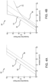
- normalized current which is located along the x-axis, is representative of the current supplied to coil 224.
- the current values on the x-axis are determined based on the current of the pressure signal output by BCU 30 (e.g., the current of pressure signal 142, 162, 182 or 202).
- Normalized servo valve pressure which is located along the y-axis, is representative of the pressure in conduit 206.
- servo valve pressure values are determined from the sensor signals output by the valve monitoring sensor (e.g., by valve monitoring sensor 150, 170, 190 or 210).
- Line 302 in graph 300 illustrates the static gain of a healthy EHSV.
- line 302 in a healthy EHSV, line 302 is generally linear and/or has a constant, linear slope when the normalized pressure is greater than 0% and less than 100% (e.g., between approximately 18% and 85% normalized current).
- the change pressure in conduit 206 is proportional to the current supplied to coil 224.
- an expected pressure may be determined from line 302.
- the points along line 302 represent the expected pressure values relative to the current provided to coil 224.
- Line 304 in graph 300 represents an upper pressure threshold.
- Line 306 represents a lower pressure threshold.
- the upper pressure threshold 304 and the lower pressure threshold 306 may a have a slope that is equal to the static gain (e.g., line 302) of a healthy EHSV between normalized pressures greater than 0% and less than 100%.
- the slope of upper pressure threshold line 304 between approximately 10% normalized current and approximately 77% normalized current may be linear and/or constant and/or parallel to line 302.
- the slope of lower pressure threshold line 306 between approximately 26% normalized current and approximately 93% normalized current may be linear and/or constant and/or parallel to line 302.
- the translation of spool 230 relative to sleeve 232 can cause spool 230 and/or sleeve 232 to wear. Wear of the spool 230 and/or of the sleeve 232 may create clearance(s) between the inner circumferential surface 233 of the sleeve 232 and the outer circumferential surface 231 of the spool 230.
- the clearance(s) may allow fluid to leak between the spool 230 and the sleeve 232 and this fluid leakage tends to result in the static gain characteristics of the servo valve no longer being linear. For example, not to be bound by theory, it is believed that leakage flow is proportional to the cube of diametrical clearance and inversely proportional to length of clearance.
- line 310 and line 312 in graph 308 illustrate the static gain of unhealthy EHSVs.
- EHSV having a worn spool, a worn sleeve and/or blockage from debris.
- the slope of line 310 which is nonlinear, indicates an EHSV is experiencing a fault condition and/or is exhibiting wear.
- line 310 crosses upper pressure threshold 304.
- the steeper than expected slope of line 310 indicates that the pressure in conduit 206 is greater than expected based on the current being provided to the EHSV coil.
- the slope of line 312, which is nonlinear also indicates an EHSV that experiencing a fault condition and/or is exhibiting wear.
- line 312 crosses lower pressure threshold 306.
- the flatter than expected slope of line 312 indicates that the pressure in conduit 206 is less than expected based on the current being provided to the EHSV coil.
- system 350 for monitoring the health of an EHSV is illustrated.
- system 350 may be installed in aircraft 10 ( FIG. 1 ). Elements of system 350 with like numbering to FIG. 2 are intending to be the same and may not necessarily be repeated for the sake of brevity. While system 350 is shown as monitoring the health of RIB EHSV, it is contemplated and understood that similar systems may be employed to monitor the health of the other EHSVs.
- System 350 includes BCU 30. BCU is configured to receive a brake command 352. Brake command 352 may be sent from cockpit controls 32 in FIG. 1 (e.g., from a pilot or autobrake system of aircraft 10), from sources external to the aircraft 10 (e.g., from a ground controller), or from onboard sensors.
- BCU 30 is configured to determine a current for pressure signal 202 based on brake command 352.
- BCU 30 sends pressure signal 202 to EHSV 200 (e.g., to coil 224 FIG. 3A ).
- Pressure signal 202 causes translation of spool 230 ( FIG. 3A ) and thereby changes (e.g., increases) the flow rate of fluid 184 through conduit 206 and/or the fluid pressure in conduit 206.
- the "flow rate" of a fluid refers to the volume of fluid flowing through an area relative to a duration of time (e.g. cubic feet or cubic meters per second).
- the change in flow rate and/or fluid pressure in conduit 206 changes the pressure applied by actuator 134 to brake stack 136.
- BCU 30 may further receive a brake pressure signal 354 from a brake pressure sensor 356.
- Brake pressure sensor 356 is configured to measure a pressure applied to brake stack 136 by actuator 134.
- the brake pressure signal 354 corresponds to the measured pressure.
- BCU 30 may determine the pressure applied to brake stack 156 based on brake pressure signal 354.
- BCU 30 may compare the pressure applied to an expected brake stack pressure 156.
- BCU 30 may determine the expected brake stack pressure based on the brake command. If the pressure applied to brake stack 156 is different from the expected brake stack pressure, BCU 30 may adjust the current of pressure signal 202.
- BCU 30 may continue to adjust the current of pressure signal 202, until the pressure applied to brake stack 156 is equal, or approximately equal, to the expected brake stack pressure.
- System 350 includes valve monitoring sensor 210.
- Valve monitoring sensor 210 is coupled to conduit 206 and is configured to measure at least one of the flow rate or the pressure in conduit 206.
- Valve monitoring sensor 210 outputs sensor signal 212 corresponding the pressure and/or flow rate measured by valve monitoring sensor 210.
- BCU receives sensor signal 212 and determines a pressure in conduit 206 based on sensor signal 212. If sensor signal 212 corresponds to a flow rate, BCU 30 may determine the pressure that corresponds to the flow rate.
- BCU 30 also determines the health of EHSV 200 based on the pressure in conduit 206.
- BCU 30 may compare the pressure in conduit 206 to an upper pressure threshold and a lower pressure threshold.
- BCU 30 may determine the upper pressure threshold and the lower pressure threshold based on the current of the pressure signal 202 sent to EHSV 200.
- BCU 30 may access a look up table stored in storage medium 110 (or any other memory accessible to BCU 30).
- the upper pressure threshold values in the lookup table may correspond to points along an upper threshold line similar to line 304 in FIGs. 4A and 4B .
- the lower pressure threshold values in the lookup table may correspond to points along a lower threshold line similar to line 306 in FIGs. 4A and 4B .
- BCU 30 may determine the upper pressure threshold and the lower pressure threshold by determining an expected pressure based on the current of pressure signal 202 and adding or subtracting a set value to or from the expected pressure to calculate the upper and lower pressure thresholds, respectively.
- the expected pressure is proportional to the current such that a slope of the expected static gain is linear.
- System 350 includes a display 358.
- BCU 30 may send display commands 360 to display 358.
- Display 358 may be configured to convey a health status of EHSV 200 to aircraft crew, ground crew, and/or maintenance personnel.
- Display 358 may be configured to output various status alerts based on the display command 360 received from BCU 30.
- the status alert output by display 358 may be images, symbols, text messages, audio messages, illuminated lights, or any other alert capable of conveying information about the health of EHSV 200 to aircraft crew, ground crew, and/or maintenance personnel.
- BCU 30 may output a first display command 360 configured to cause display 358 to output an immediate maintenance needed (or first) alert in response to BCU 30 determining the pressure in conduit 206 is greater than the upper pressure threshold or less than the lower pressure threshold.
- the immediate maintenance needed alert is configured to convey to aircraft crew, ground crew, and/or maintenance personnel that maintenance and/or replacement of one or more components of EHSV 200 is needed immediately.
- BCU 30 may output a second display command 360 configured to cause display 358 to output a warning (or second) alert in response to BCU 30 determining the pressure in conduit 206 is less than the upper pressure threshold and that the difference between the pressure in conduit 206 and the upper pressure threshold is less than a threshold difference (e.g., in response to the determining the pressure in conduit 206 is approaching the upper pressure threshold).
- BCU 30 may similarly output the second display command 360 configured to cause display 358 to output the warning alert in response to BCU 30 determining the pressure in conduit 206 is greater than the lower pressure threshold and the difference between the pressure in conduit 206 and the lower pressure threshold is less than the threshold difference (e.g., in response to determining the pressure in conduit 206 is approaching the lower pressure threshold).
- the warning alert may be configured to convey to aircraft crew, ground crew, and/or maintenance personnel that maintenance of EHSV 200 should be scheduled. Alerting that maintenance should be scheduled tends to allow aircraft operators to better plan the aircraft's availability and/or reduces occurrences of unexpected and/or immediate maintenance operations.
- method 400 for monitoring an electrohydraulic servo valve of an aircraft landing gear is shown.
- method 400 may be carried out by system 350.
- one or more of the steps of method 400 may be performed by BCU 30.
- method 400 may comprise receiving a brake command (step 402).
- Step 402 may include BCU 30 receiving brake command 352 from, for example, cockpit controls 32 ( FIG. 1 ).
- Method 400 further includes BCU 30 outputting pressure signal 202 to the EHSV 200 based on the brake command 352 (step 404) and BCU 30 receiving sensor signal 212 from valve monitoring sensor 210 (step 406) with valve monitoring sensor 210 being configured to measure at least one of the pressure or the fluid flow in conduit 206, which is fluidly coupled to control port 242 of EHSV 200.
- Method 400 may further include BCU 30 determining the health of the EHSV 200 based on the sensor signal 212 (step 408).
- step 408 may include BCU 30 determining an upper pressure threshold and a lower pressure threshold based on the current of pressure signal 202 (step 408A).
- BCU 30 may determine the upper pressure threshold by determining an expected pressure of the conduit 206 based on the current of the pressure signal and then adding a first value to the expected pressure.
- BCU 30 may determine the lower pressure threshold by determining the expected pressure of the conduit 206 based on the current of the pressure signal 202 and then subtracting a second value from the expected pressure. The second value may be equal to or different from the first value.
- BCU 30 may determine the upper pressure threshold by locating a point on an upper threshold line (e.g., line 304 in FIG. 5A) corresponding the current of the pressure signal 202, where the upper pressure threshold line 304 is a linear line and has a constant slope.
- BCU 30 may determine the lower pressure threshold by locating a point on a lower threshold line (e.g., line 306 in FIG. A) corresponding the current of the pressure signal 202.
- the lower pressure threshold line 306 is parallel to the upper pressure threshold line 304.
- step 408 may further include BCU 30 determining the pressure in the conduit 206 based on the sensor signal 212 (step 408B) and BCU 30 comparing the pressure in the conduit 206 to the upper pressure threshold and to the lower pressure threshold (step 408C).
- method 400 may further comprise BCU 30 commanding display 358 to output an alert in response to BC determining that the pressure in the conduit 206 is greater than the upper pressure threshold or that the pressure in the conduit is less than the lower pressure threshold (step 410A).
- step 408C may include BCU 30 determining a first difference between the pressure in the conduit 16 and the upper pressure threshold and a second difference between the pressure in the conduit 206 and the lower pressure threshold (step 408C-1). BCU 30 may then compare each of the first difference and second difference to a difference threshold (step 408C-2). In various embodiments, the first difference and the second difference may be compared to the same difference threshold. In various embodiments, a first difference threshold used for the first difference may be different from a second difference threshold used for the second difference.
- method 400 may further include BCU 30 commanding display 358 to output a warning alert, in response to at least one of the first difference or the second difference being less than the difference threshold (step 410B).
- references to "various embodiments”, “one embodiment”, “an embodiment”, “an example embodiment”, etc. indicate that the embodiment described may include a particular feature, structure, or characteristic, but every embodiment may not necessarily include the particular feature, structure, or characteristic. Moreover, such phrases are not necessarily referring to the same embodiment. Further, when a particular feature, structure, or characteristic is described in connection with an embodiment, it is submitted that it is within the knowledge of one skilled in the art to affect such feature, structure, or characteristic in connection with other embodiments whether or not explicitly described. After reading the description, it will be apparent to one skilled in the relevant art(s) how to implement the disclosure in alternative embodiments.
Landscapes
- Engineering & Computer Science (AREA)
- Transportation (AREA)
- Mechanical Engineering (AREA)
- Aviation & Aerospace Engineering (AREA)
- Valves And Accessory Devices For Braking Systems (AREA)
Abstract
Description
- This application claims priority to, and the benefit of,
India Patent Application No. 202241012758, filed March 9, 2022 - The present disclosure relates to valves and, in particular, to systems and methods for monitoring a health of a landing gear servo valve.
- Aircraft typically include a braking system operatively coupled to the wheels of the aircraft and configured to slow the wheels, and the aircraft, during, for example, landing or a rejected takeoff. Brake systems typically employ a series of friction disks located about an axle. The friction disks may be compressed together to stop the aircraft. The compression of the friction disks may be controlled by one or more hydraulic actuator(s). Hydraulic fluid is typically provided to the hydraulic actuators via flexible hosing or tubing that is connected to a hydraulic fluid source located proximate the aircraft fuselage or wing. A servo valve controls the flow of the hydraulic fluid to and from the brake actuators. Wear of the servo valve can lead to performance degradation and/or improper function of the brake system.
- A system for monitoring an electrohydraulic servo valve is disclosed herein. In accordance with various embodiments, the system may comprise a brake control unit, a valve monitoring sensor configured to measure at least one of a pressure or a fluid flow rate in a conduit fluidly connected to a control port of the electrohydraulic servo valve, and a tangible, non-transitory memory configured to communicate with the brake control unit. The tangible, non-transitory memory has instructions stored thereon that, in response to execution by the brake control unit, cause the brake control unit to perform operations, which may comprise receiving, by the brake control unit, a brake command; outputting, by the brake control unit, a pressure signal to the electrohydraulic servo valve based on the brake command; receiving, by the brake control unit, a sensor signal from the valve monitoring sensor; and determining, by the brake control unit, a health of the electrohydraulic servo valve based on the sensor signal.
- In various embodiments, determining, by the brake control unit, the health of the electrohydraulic servo valve based on the sensor signal may comprise determining, by the brake control unit, an upper pressure threshold based on a current of the pressure signal; determining, by the brake control unit, a lower pressure threshold based on the current of the pressure signal; determining, by the brake control unit, the pressure in the conduit based on the sensor signal; and comparing, by the brake control unit, the pressure in the conduit to the upper pressure threshold and the lower pressure threshold.
- In various embodiments, the operations may further comprise commanding, by the brake control unit, a display to output an alert in response to at least one of determining, by the brake control unit, the pressure in the conduit is greater than the upper pressure threshold; or determining, by the brake control unit, the pressure in the conduit is less than the lower pressure threshold.
- In various embodiments, the operations may further comprise determining, by the brake control unit, a first difference between the pressure in the conduit and the upper pressure threshold; determining by the brake control unit, a second difference between the pressure in the conduit and the lower pressure threshold; and comparing, by the brake control unit, each of the first difference and the second different to a difference threshold.
- In various embodiments, the operations may further comprise commanding, by the brake control unit, a display to output a warning alert, in response to at least one of the first difference or the second difference being less than the difference threshold.
- In various embodiments, determining, by the brake control unit, the upper pressure threshold based on the current of the pressure signal may comprise determining, by the brake control unit, an expected pressure of the conduit based on the current of the pressure signal; and adding, by the brake control unit, a first value to the expected pressure.
- In various embodiments, determining, by the brake control unit, the upper pressure threshold based on the current of the pressure signal may comprise locating, by the brake control unit, a point on an upper threshold line corresponding the current of the pressure signal. The upper threshold line may be a linear line having a constant slope.
- A method for monitoring an electrohydraulic servo valve of an aircraft landing gear is also disclosed herein. In accordance with various embodiments, the method may comprise the steps of receiving, by a brake control unit, a brake command; outputting, by the brake control unit, a pressure signal to the electrohydraulic servo valve based on the brake command; receiving, by the brake control unit, a sensor signal from a valve monitoring sensor; and determining, by the brake control unit, a health of the electrohydraulic servo valve based on the sensor signal. The valve monitoring sensor may be configured to measure at least one of a pressure or a fluid flow rate in a conduit fluidly coupled to a control port of the electrohydraulic servo valve
- In various embodiments, determining, by the brake control unit, the health of the electrohydraulic servo valve based on the sensor signal may comprise determining, by the brake control unit, an upper pressure threshold based on a current of the pressure signal; determining, by the brake control unit, a lower pressure threshold based on the current of the pressure signal; determining, by the brake control unit, the pressure in the conduit based on the sensor signal; and comparing, by the brake control unit, the pressure in the conduit to the upper pressure threshold and to the lower pressure threshold.
- In various embodiments, the method may further comprise commanding, by the brake control unit, a display to output an alert in response to at least one of determining, by the brake control unit, the pressure in the conduit is greater than the upper pressure threshold; or determining, by the brake control unit, the pressure in the conduit is less than the lower pressure threshold.
- In various embodiments, comparing, by the brake control unit, the pressure in the conduit to the upper pressure threshold and to the lower pressure threshold may comprise determining, by the brake control unit, a first difference between the pressure in the conduit and the upper pressure threshold; determining by the brake control unit, a second difference between the pressure in the conduit and the lower pressure threshold; and comparing, by the brake control unit, each of the first difference and the second different to a difference threshold.
- In various embodiments, the method may further comprise commanding, by the brake control unit, the display to output a warning alert, in response to at least one of the first difference or the second difference being less than the difference threshold.
- In various embodiments, determining, by the brake control unit, the upper pressure threshold based on the current of the pressure signal may comprise determining, by the brake control unit, an expected pressure of the conduit based on the current of the pressure signal; and adding, by the brake control unit, a first value to the expected pressure.
- In various embodiments, determining, by the brake control unit, the upper pressure threshold based on the current of the pressure signal may comprise locating, by the brake control unit, a point on an upper threshold line corresponding the current of the pressure signal. The upper threshold line may be a linear line having a constant slope.
- In various embodiments, determining, by the brake control unit, the lower pressure threshold based on the current of the pressure signal may comprise locating, by the brake control unit, a point on a lower threshold line corresponding the current of the pressure signal. The lower threshold line may be parallel to the upper threshold line.
- A landing gear is also disclosed herein. In accordance with various embodiments, the landing gear may comprise a brake assembly including a brake stack and an actuator configured to apply pressure to the brake stack, an electrohydraulic servo valve configured to control a flow of fluid to the brake assembly, a conduit fluidly connecting a control port of the electrohydraulic servo valve and an inlet of the actuator, a valve monitoring sensor configured to measure at least one of a pressure or a fluid flow rate in the conduit, and a brake control unit in communication with the electrohydraulic servo valve and the valve monitoring sensor. The brake control unit may be configured to output a pressure signal to the electrohydraulic servo valve and to receive a sensor signal from the valve monitoring sensor. The brake control unit may be configured to determine a health of the electrohydraulic servo valve based on the sensor signal and the pressure signal.
- In various embodiments, the brake control unit may determine the health of the electrohydraulic servo valve by determining an upper pressure threshold and a lower pressure threshold based on a current of the pressure signal, determining the pressure in the conduit based on the sensor signal, and comparing the pressure in the conduit to the upper pressure threshold and the lower pressure threshold.
- In various embodiments, the brake control unit may be configured to determine a first difference between the pressure in the conduit and the upper pressure threshold and a second difference between the pressure in the conduit and the lower pressure threshold.
- In various embodiments, the brake control unit may be configured to command a display to output a first alert in response to determining at least one of the pressure in the conduit is greater than the upper pressure threshold or the pressure in the conduit is less than the lower pressure threshold.
- In various embodiments, the brake control unit may be configured to command the display to output a second alert, different from the first alert, in response to determining at least one of the pressure in the conduit is less than or equal to the upper pressure threshold and the first difference is less than a difference threshold, or the pressure in the conduit is greater than or equal to the lower pressure threshold and the second difference is less than the difference threshold.
- The foregoing features and elements may be combined in various combinations without exclusivity, unless expressly indicated otherwise. These features and elements as well as the operation thereof will become more apparent in light of the following description and the accompanying drawings. It should be understood, however, the following description and drawings are intended to be exemplary in nature and non-limiting.
- The subject matter of the present disclosure is particularly pointed out and distinctly claimed in the concluding portion of the specification. A more complete understanding of the present disclosure, however, may best be obtained by referring to the detailed description and claims when considered in connection with the figures, wherein like numerals denote like elements.
-
FIG. 1 illustrates an aircraft, in accordance with various embodiments; -
FIG. 2 illustrates a brake system for an aircraft, in accordance with various embodiments; -
FIG. 3A illustrates an electrohydraulic servo valve in a first position, in accordance with various embodiments; -
FIG. 3B illustrates the electrohydraulic servo valve ofFIG. 3A in a second position, in accordance with various embodiments; -
FIG. 3C illustrates translations of the electrohydraulic servo valve ofFIG. 3B in a second axial direction, in accordance with various embodiments; -
FIG. 4A and 4B illustrate a graphical representation of current versus servo valve pressure for an electrohydraulic servo valve in a healthy condition and in a fault condition, respectively, in accordance with various embodiments; -
FIG. 5 illustrates a schematic of a system for monitoring health of an electrohydraulic servo valve, in accordance with various embodiments; and -
FIGs. 6A ,6B , and6C illustrate a method for monitoring health of an electrohydraulic servo valve, in accordance with various embodiments. - The detailed description of exemplary embodiments herein makes reference to the accompanying drawings, which show exemplary embodiments by way of illustration. While these exemplary embodiments are described in sufficient detail to enable those skilled in the art to practice the exemplary embodiments of the disclosure, it should be understood that other embodiments may be realized and that logical changes and adaptations in design and construction may be made within the scope of the claims. Thus, the detailed description herein is presented for purposes of illustration only and not limitation. The steps recited in any of the method or process descriptions may be executed in any order and are not necessarily limited to the order presented, and are limited only by the claims.
- Furthermore, any reference to singular includes plural embodiments, and any reference to more than one component or step may include a singular embodiment or step.
- Cross-hatching may be used throughout the figures to denote different parts but not necessarily to denote the same or different materials. Throughout the present disclosure, like reference numbers denote like elements. Accordingly, elements with like element numbering may be shown in the figures but may not necessarily be repeated for the sake of brevity.
- With reference to
FIG. 1 , anaircraft 10 including afuselage 11 andwings 13 is illustrated, in accordance with various embodiments.Aircraft 10 includes landing gear such asleft landing gear 12,right landing gear 14, andnose landing gear 16.Left landing gear 12,right landing gear 14, andnose landing gear 16 may generally supportaircraft 10 whenaircraft 10 is not flying, allowingaircraft 10 to taxi, take off, and land without damage.Left landing gear 12 may include left outboard (LOB)wheel 13A and left inboard (LIB)wheel 13B coupled by anaxle 20.Right landing gear 14 may include right outboard (ROB)wheel 15A and right inboard (RIB)wheel 15B coupled by anaxle 22.Nose landing gear 16 may includeleft nose wheel 17A andright nose wheel 17B coupled by anaxle 24. The nose wheels may differ from the left and right landing gear wheels in that the nose wheels may not include a brake. -
Aircraft 10 may comprise a brake control unit (BCU) 30 and cockpit controls 32. In various embodiments, theBCU 30 may be located in the fuselage of the aircraft.Left landing gear 12 andright landing gear 14 may be in communication withBCU 30 and may receive commands fromBCU 30. For example,BCU 30 may send brake commands to leftlanding gear 12 andright landing gear 14 based on signals received from cockpit controls 32 (e.g., from a pilot or autobrake system), from sources external to the aircraft (e.g., from a ground controller), or from onboard sensors. - With reference to
FIG. 2 , abrake system 100 is shown, in accordance with various embodiments. In various embodiments,brake system 100 may be configured to control braking ofleft landing gear 12 andright landing gear 14.Brake system 100 may include aLOB brake assembly 102 coupled toLOB wheel 13A, aLIB brake assembly 104 coupled toLIB wheel 13B, aROB brake assembly 106 coupled toROB wheel 15A, and aRIB brake assembly 108 coupled toRIB wheel 15B. WhileFIG. 2 illustratesbrake system 100 comprising two landing gears (i.e., leftlanding gear 12 and right landing gear 14) with four total wheels, it is further contemplated and understood that the systems and methods described herein may apply to brake systems comprising any number of landing gears and/or number of wheels per landing gear. -
Brake assemblies Brake assemblies LOB brake assembly 102 includes a LOB actuator 122 and aLOB brake stack 124,LIB brake assembly 104 includes aLIB actuator 126 and aLIB brake stack 128,ROB brake assembly 106 includes aROB actuator 130 and aROB brake stack 132, andRIB brake assembly 108 includes aRIB actuator 134 and aRIB brake stack 136. Each of thebrake actuators - In accordance with various embodiments,
BCU 30 controls the pressure applied bybrake actuators LOB EHSV 140 is operably coupled toBCU 30 and LOB actuator 122, aLIB EHSV 160 is operably coupled toBCU 30 and LIB actuator 126, aROB EHSV 180 is operably coupled toBCU 30 andROB actuator 130, and aRIB EHSV 200 is operably coupled toBCU 30 andRIB actuator 134. -
BCU 30 may include a general-purpose processor, a digital signal processor (DSP), an application specific integrated circuit (ASIC), a field programmable gate array (FPGA), or some other programmable logic device, discrete gate or transistor logic, discrete hardware components, or any combination thereof. A tangible, non-transitory computer-readable storage medium 110 may be in communication withBCU 30. Thestorage medium 110 may comprise any tangible, non-transitory computer-readable storage medium known in the art. Thestorage medium 110 has instructions stored thereon that, in response to execution byBCU 30,cause BCU 30 to perform operations related to monitoring a health ofEHSVs - The term "non-transitory" is to be understood to remove only propagating transitory signals per se from the claim scope and does not relinquish rights to all standard computer-readable media that are not only propagating transitory signals per se.
- In accordance with various embodiments,
LOB EHSV 140 receives LOB pressure signals 142 fromBCU 30 and providesfluid 144 to LOB actuator 122.LOB EHSV 140 may be fluidly connected to and may receive fluid 144 from afluid source 156.LOB EHSV 140 modulates the flow rate and/or pressure of the fluid 144 provided to LOB actuator 122 based on the LOB pressure signal 142 received fromBCU 30. In various embodiments, the pressure of the fluid 144 in the conduit (or fluid path) 146 connecting an outlet ofLOB EHSV 140 and an inlet of LOB actuator 122 is proportional to the current of the LOB pressure signal 142 sent byBCU 30. Thus, the pressure applied by LOB actuator 122 toLOB brake stack 124 may be proportional to the current ofLOB pressure signal 142. For example,BCU 30 may increase or decrease a pressure applied toLOB brake stack 124 by increasing or decreasing, respectively, the current ofLOB pressure signal 142. - In accordance with various embodiments, a LOB
valve monitoring sensor 150 may be coupled toconduit 146. LOBvalve monitoring sensor 150 is configured to measure a pressure and/or flow rate of the fluid 144 inconduit 146. In this regard, LOBvalve monitoring sensor 150 is located between the outlet ofLOB EHSV 140 and the inlet of LOB actuator 122. LOBvalve monitoring sensor 150 outputs asensor signal 152 corresponding to the pressure and/or fluid flow rate inconduit 146 toBCU 30. Stated differently,BCU 30 receivessensor signal 152 from LOBvalve monitoring sensor 150 and determines a pressure and/or a flow rate inconduit 146 based on thesensor signal 152. As described in further detail below,BCU 30 is configured to monitor a health ofLOB EHSV 140 usingsensor signal 152. - In accordance with various embodiments,
LIB EHSV 160 receives LIB pressure signals 162 fromBCU 30 and providesfluid 144 toLIB actuator 126.LOB EHSV 140 may be fluidly connected to and may receive fluid 144 fromfluid source 156. WhileFIG. 2 showsLOB EHSV 140 andLIB EHSV 160 both receiving fluid fromfluid source 156, in various embodiments,LOB EHSV 140 andLIB EHSV 160 may each have their own dedicated fluid source. In accordance with various embodiments,LIB EHSV 160 modulates the flow rate and/or pressure of the fluid 144 provided toLIB actuator 126 based on a LIB pressure signal 162 received fromBCU 30. In various embodiments, the pressure of the fluid 144 in the conduit (or flow path) 166 connecting an outlet ofLIB EHSV 160 and an inlet ofLIB actuator 126 is proportional to the current of the LIB pressure signal 162 sent byBCU 30. Thus, the pressure applied byLIB actuator 126 toLIB brake stack 128 may be proportional to the current ofLIB pressure signal 162. For example,BCU 30 may increase or decrease a pressure applied toLIB brake stack 128 by increasing or decreasing, respectively, the current ofLIB pressure signal 162. - In accordance with various embodiments, a LIB
valve monitoring sensor 170 may be coupled toconduit 166. LIBvalve monitoring sensor 170 is configured to measure a pressure and/or flow rate of the fluid 144 inconduit 166. In this regard, LIBvalve monitoring sensor 170 is located between the outlet ofLIB EHSV 160 and the inlet ofLIB actuator 126. LIBvalve monitoring sensor 170 outputs a sensor signal 172 toBCU 30. Sensor signal 172 corresponds to (i.e., is indicative of) the pressure and/or fluid flow rate inconduit 166. Stated differently,BCU 30 receives sensor signal 172 from LIBvalve monitoring sensor 170 and determines a pressure and/or a flow rate inconduit 166 based on the sensor signal 172. As described in further detail below,BCU 30 is configured to monitor a health ofLIB EHSV 160 based on sensor signal 172. - In accordance with various embodiments,
ROB EHSV 180 receives ROB pressure signals 182 fromBCU 30 and provides a fluid 184 toROB actuator 130.ROB EHSV 180 may be fluidly connected to and may receive fluid 184 from afluid source 196.ROB EHSV 180 modulates the flow rate and/or pressure of the fluid 184 provided toROB actuator 130 based on the ROB pressure signal 182 received fromBCU 30. In various embodiments, the pressure and/or flow rate of the fluid 184 in a conduit 186 (or flow path) connectingROB EHSV 180 andROB actuator 130 is proportional to the current of the ROB pressure signal 182 sent byBCU 30. Thus, the pressure applied byROB actuator 130 toROB brake stack 132 may be proportional to the current ofROB pressure signal 182. For example,BCU 30 may increase or decrease a pressure applied toROB brake stack 132 by increasing or decreasing, respectively, the current ofROB pressure signal 182. - In accordance with various embodiments, a ROB
valve monitoring sensor 190 may be coupled toconduit 186. In this regard, ROBvalve monitoring sensor 190 is located between the outlet ofROB EHSV 180 and the inlet ofROB actuator 130. ROBvalve monitoring sensor 190 is configured to measure a pressure and/or flow rate of the fluid 184 inconduit 186. ROBvalve monitoring sensor 190 outputs a sensor signal 192 toBCU 30 corresponding to the pressure and/or fluid flow rate inconduit 186. Stated differently,BCU 30 receives sensor signal 192 from ROBvalve monitoring sensor 190 and determines a pressure and/or a flow rate inconduit 186 based on the sensor signal 192. As described in further detail below,BCU 30 is configured to monitor a health ofROB EHSV 180 using sensor signal 192. - In accordance with various embodiments,
RIB EHSV 200 receives RIB pressure signals 202 fromBCU 30 and providesfluid 184 toRIB actuator 134.RIB EHSV 200 may be fluidly connected to and may receive fluid 184 fromfluid source 196. WhileFIG. 2 showsROB EHSV 180 andRIB EHSV 200 both receiving fluid 184 fromfluid source 196, in various embodiments,ROB EHSV 180 andRIB EHSV 200 may each have their own dedicated fluid source. In various embodiments,LOB EHSV 140,LIB EHSV 160,ROB EHSV 180, andRIB EHSV 200 may be fluidly connected to the same fluid source. -
RIB EHSV 200 is configured to modulate the flow rate and/or pressure of the fluid 184 provided toRIB actuator 134 based on theRIB pressure signal 202 received fromBCU 30. In various embodiments, the pressure and/or flow rate of the fluid 184 in the conduit (or flow path) 206 connectingRIB EHSV 200 andRIB actuator 134 is proportional to the current of theRIB pressure signal 202 sent byBCU 30. Thus, the pressure applied byRIB actuator 134 toRIB brake stack 136 may be proportional to the current ofRIB pressure signal 202. For example,BCU 30 may increase or decrease a pressure applied toRIB brake stack 136 by increasing or decreasing, respectively, the current ofRIB pressure signal 202. - In accordance with various embodiments, a RIB
valve monitoring sensor 210 may be coupled toconduit 206. In this regard, RIBvalve monitoring sensor 210 is located between the outlet ofRIB EHSV 200 and the inlet ofRIB actuator 134. RIBvalve monitoring sensor 210 is configured to measure a pressure and/or flow rate of the fluid 184 inconduit 206. RIBvalve monitoring sensor 210 outputs asensor signal 212 toBCU 30 corresponding to the pressure and/or fluid flow rate inconduit 206. Stated differently,BCU 30 receivessensor signal 212 from RIBvalve monitoring sensor 210 and determines a pressure and/or a flow rate inconduit 206 based on thesensor signal 212. As described in further detail below,BCU 30 is configured to monitor a health ofRIB EHSV 200 usingsensor signal 212. - With reference to
FIG. 3A , additional details ofRIB EHSV 200 are illustrated. WhileFIGs. 3A ,3B , and3C illustrate components ofRIB EHSV 200, it should be understood thatLOB EHSV 140,LIB EHSV 160, andROB EHSV 180 include the elements and functionalities as described herein with respect toRIB EHSV 200. In accordance with various embodiments,RIB EHSV 200 includes atorque motor 220.Torque motor 220 includes anarmature 222 and acoil 224. -
RIB EHSV 200 further includes aspool 230 and asleeve 232.Sleeve 232 is configured to surround an outercircumferential surface 231 ofspool 230. A diameter ofspool 230 may be varied along outercircumferential surface 231. Outercircumferential surface 231 andsleeve 232 may define various flow paths aboutspool 230. In this regard,sleeve 232 contacts portions of outercircumferential surface 231, thereby forming a sealing interface with the contacted portions of outercircumferential surface 231, andsleeve 232 is spaced apart from other portions of outercircumferential surface 231, thereby forming flow paths between the outercircumferential surface 231 ofspool 230 and an innercircumferential surface 233 ofsleeve 232. In various embodiments, one or more fluid path may also be formed through an interior ofspool 230. -
Spool 230 is configured to translate relative to and withinsleeve 232. In this regard,spool 230 may translate axially alongaxis A. Sleeve 232 may be located about axis A. Aflapper 226 is attached toarmature 222. In response to receiving current in a first, or positive, direction (e.g., in response to a first pressure signal 202 (FIG. 2 )),coil 224 generates a first magnetic field. The first magnetic field is configured to translatearmature 222 in a first direction, thereby drivingflapper 226 toward and/or into contact with a first nozzle 228 (as shown inFIG. 3B ). In response to receiving current in a second, or negative, direction (e.g., in response to a second pressure signal 202 (FIG. 2 )),coil 224 generates a second magnetic field in the opposite direction of the first magnetic field. The second magnetic field is configured to translatearmature 222 in a second direction, thereby drivingflapper 226 toward and/or into contact with a second nozzle 229 (as shown inFIG. 3C ). - With reference to
FIG. 3B , translation offlapper 226 into contact withfirst nozzle 228 increases the fluid pressure in within afirst pressure stage 234 ofRIB EHSV 200.First pressure stage 234 may be defined, at least partially, by afirst end 236 ofspool 230. The increase in fluid pressure infirst pressure stage 234 increases a pressure exerted onfirst end 236 ofspool 230 and thereby forces spool 230 to translate in a first axial direction D1. With reference toFIG. 3C , translation offlapper 226 into contact with second nozzle 129 increases the fluid pressure in within asecond pressure stage 238 ofRIB EHSV 200.Second pressure stage 238 may be defined, at least partially, by asecond end 239 ofspool 230. The increase in fluid pressure insecond pressure stage 238 increases the pressure exerted onsecond end 239 ofspool 230 and thereby forces spool 230 to translate in a second axial direction D2. Thus, the axial direction of translation ofspool 230 may be controlled by applying current in either the first direction (e.g., positive current) or in the second direction (e.g., negative current) tocoil 224. -
RIB EHSV 200 includes asupply port 240. With combined reference toFIG. 2 andFIG. 3A , fluid 184 (FIG. 2 ) from fluid source 196 (FIG. 2 ) may be received atsupply port 240. Stated differently, the fluid 184 fromfluid source 196 flows intoRIB EHSV 200 viasupply port 240. In various embodiments, afilter assembly 246 may be fluidly coupled to supplyport 240 such that fluid flows intofilter assembly 246 upon enteringRIB EHSV 200 viasupply port 240.Filter assembly 246 may define multiple orifices and flow paths configured to fluidly connectsupply port 240 to various components ofRIB EHSV 200. -
RIB EHSV 200 also includes acontrol port 242. Conduit 206 (FIG. 2 ) may be fluidly connected to control port 242 (e.g.,control port 242 may form an outlet of RIB EHSV 200). Fluid 184 (FIG. 2 ) may flow between conduit 206 (FIG. 2 ) andRIB EHSV 200 viacontrol port 242. - In
FIG. 3A ,spool 230 is illustrated in a first, or closed, position. In the first position,supply port 240 may be fluidly sealed fromcontrol port 242. Stated differently, in the first position,spool 230 may block fluid fromsupply port 240 from reachingcontrol port 242. InFIG. 3B ,spool 230 is illustrated in a second, or open, position. In the second position,supply port 240 is fluidly connected to controlport 242. Stated differently, in the second position,spool 230 andsleeve 232 may define a fluid path that allows the fluid fromsupply port 240 to reachcontrol port 242. - In various embodiments, the second position may represent a fully open, or 100% open, position and the first position may represent a closed, or 0% open, position. The position of
spool 230 between the fully open position and the closed position (i.e., the 100% open position and 0% open position) may be controlled by the amount of current supplied tocoil 224. For example,spool 230 may be located between the fully open and close position (e.g., at a 25% open position, a 50% open position, a 75% open position, etc.) and the current applied tocoil 224 may control the position ofspool 230. The pressure in conduit 206 (FIG. 2 ) may be proportional to the position ofspool 230 and increasing the open percentage increases the pressure and/or flow rate of fluid 184 (FIG. 2 ) in conduit 206 (FIG. 2 ). Thus, the pressure and/or flow rate of fluid 184 (FIG. 2 ) is also proportional to the current applied to coil 224 (e.g., an increase in the current, increases the pressure and flow rate in conduit 206). - With reference
FIG. 4A , agraphical representation 300 of normalized servo valve pressure versus normalized current is illustrated. With combined reference toFIGs. 4A ,2 , and3A , normalized current, which is located along the x-axis, is representative of the current supplied tocoil 224. In this regard, the current values on the x-axis are determined based on the current of the pressure signal output by BCU 30 (e.g., the current ofpressure signal conduit 206. In this regard, servo valve pressure values are determined from the sensor signals output by the valve monitoring sensor (e.g., byvalve monitoring sensor Line 302 ingraph 300 illustrates the static gain of a healthy EHSV. As shown ingraph 300, in a healthy EHSV,line 302 is generally linear and/or has a constant, linear slope when the normalized pressure is greater than 0% and less than 100% (e.g., between approximately 18% and 85% normalized current). Thus, in a healthy EHSV, the change pressure inconduit 206 is proportional to the current supplied tocoil 224. In accordance with various embodiments, an expected pressure may be determined fromline 302. In this regard, the points alongline 302 represent the expected pressure values relative to the current provided tocoil 224. -
Line 304 ingraph 300 represents an upper pressure threshold.Line 306 represents a lower pressure threshold. Theupper pressure threshold 304 and thelower pressure threshold 306 may a have a slope that is equal to the static gain (e.g., line 302) of a healthy EHSV between normalized pressures greater than 0% and less than 100%. In this regard, the slope of upperpressure threshold line 304 between approximately 10% normalized current and approximately 77% normalized current may be linear and/or constant and/or parallel toline 302. Similarly, the slope of lowerpressure threshold line 306 between approximately 26% normalized current and approximately 93% normalized current may be linear and/or constant and/or parallel toline 302. - The translation of
spool 230 relative tosleeve 232 can causespool 230 and/orsleeve 232 to wear. Wear of thespool 230 and/or of thesleeve 232 may create clearance(s) between the innercircumferential surface 233 of thesleeve 232 and the outercircumferential surface 231 of thespool 230. The clearance(s) may allow fluid to leak between thespool 230 and thesleeve 232 and this fluid leakage tends to result in the static gain characteristics of the servo valve no longer being linear. For example, not to be bound by theory, it is believed that leakage flow is proportional to the cube of diametrical clearance and inversely proportional to length of clearance. With increase in wear at spool-sleeve interface, diametric clearance increases as a cubical function resulting in loss of the linearity of static gain characteristics of the EHSV. Similarly, debris may also find its way into the EHSV and/or cause fluid flow blockage, which can result in the loss of the linearity of static gain characteristics of the EHSV. - For example, with reference to
FIG. 4B ,line 310 andline 312 ingraph 308 illustrate the static gain of unhealthy EHSVs. For example, EHSV having a worn spool, a worn sleeve and/or blockage from debris. The slope ofline 310, which is nonlinear, indicates an EHSV is experiencing a fault condition and/or is exhibiting wear. Further, at approximately 58% normalized current,line 310 crossesupper pressure threshold 304. The steeper than expected slope ofline 310 indicates that the pressure inconduit 206 is greater than expected based on the current being provided to the EHSV coil. Similarly, the slope ofline 312, which is nonlinear, also indicates an EHSV that experiencing a fault condition and/or is exhibiting wear. Further, at approximately 65% normalized current,line 312 crosseslower pressure threshold 306. The flatter than expected slope ofline 312 indicates that the pressure inconduit 206 is less than expected based on the current being provided to the EHSV coil. - With reference to
FIG. 5 , asystem 350 for monitoring the health of an EHSV is illustrated. In various embodiments,system 350 may be installed in aircraft 10 (FIG. 1 ). Elements ofsystem 350 with like numbering toFIG. 2 are intending to be the same and may not necessarily be repeated for the sake of brevity. Whilesystem 350 is shown as monitoring the health of RIB EHSV, it is contemplated and understood that similar systems may be employed to monitor the health of the other EHSVs.System 350 includesBCU 30. BCU is configured to receive abrake command 352.Brake command 352 may be sent from cockpit controls 32 inFIG. 1 (e.g., from a pilot or autobrake system of aircraft 10), from sources external to the aircraft 10 (e.g., from a ground controller), or from onboard sensors. -
BCU 30 is configured to determine a current forpressure signal 202 based onbrake command 352.BCU 30 sends pressure signal 202 to EHSV 200 (e.g., tocoil 224FIG. 3A ).Pressure signal 202 causes translation of spool 230 (FIG. 3A ) and thereby changes (e.g., increases) the flow rate offluid 184 throughconduit 206 and/or the fluid pressure inconduit 206. As used here, the "flow rate" of a fluid refers to the volume of fluid flowing through an area relative to a duration of time (e.g. cubic feet or cubic meters per second). The change in flow rate and/or fluid pressure inconduit 206 changes the pressure applied byactuator 134 tobrake stack 136. -
BCU 30 may further receive a brake pressure signal 354 from abrake pressure sensor 356.Brake pressure sensor 356 is configured to measure a pressure applied tobrake stack 136 byactuator 134. Thebrake pressure signal 354 corresponds to the measured pressure. In this regard,BCU 30 may determine the pressure applied tobrake stack 156 based onbrake pressure signal 354.BCU 30 may compare the pressure applied to an expectedbrake stack pressure 156.BCU 30 may determine the expected brake stack pressure based on the brake command. If the pressure applied tobrake stack 156 is different from the expected brake stack pressure,BCU 30 may adjust the current ofpressure signal 202.BCU 30 may continue to adjust the current ofpressure signal 202, until the pressure applied tobrake stack 156 is equal, or approximately equal, to the expected brake stack pressure. -
System 350 includesvalve monitoring sensor 210.Valve monitoring sensor 210 is coupled toconduit 206 and is configured to measure at least one of the flow rate or the pressure inconduit 206.Valve monitoring sensor 210outputs sensor signal 212 corresponding the pressure and/or flow rate measured byvalve monitoring sensor 210. BCU receivessensor signal 212 and determines a pressure inconduit 206 based onsensor signal 212. Ifsensor signal 212 corresponds to a flow rate,BCU 30 may determine the pressure that corresponds to the flow rate. - In accordance with various embodiments,
BCU 30 also determines the health ofEHSV 200 based on the pressure inconduit 206. In this regard,BCU 30 may compare the pressure inconduit 206 to an upper pressure threshold and a lower pressure threshold.BCU 30 may determine the upper pressure threshold and the lower pressure threshold based on the current of thepressure signal 202 sent toEHSV 200. In this regard,BCU 30 may access a look up table stored in storage medium 110 (or any other memory accessible to BCU 30). The upper pressure threshold values in the lookup table may correspond to points along an upper threshold line similar toline 304 inFIGs. 4A and 4B . The lower pressure threshold values in the lookup table may correspond to points along a lower threshold line similar toline 306 inFIGs. 4A and 4B . - In various embodiments,
BCU 30 may determine the upper pressure threshold and the lower pressure threshold by determining an expected pressure based on the current ofpressure signal 202 and adding or subtracting a set value to or from the expected pressure to calculate the upper and lower pressure thresholds, respectively. The expected pressure is proportional to the current such that a slope of the expected static gain is linear. -
BCU 30 compares the pressure inconduit 206 to the upper and lower pressure threshold.System 350 includes adisplay 358.BCU 30 may send display commands 360 to display 358.Display 358 may be configured to convey a health status ofEHSV 200 to aircraft crew, ground crew, and/or maintenance personnel.Display 358 may be configured to output various status alerts based on thedisplay command 360 received fromBCU 30. The status alert output bydisplay 358 may be images, symbols, text messages, audio messages, illuminated lights, or any other alert capable of conveying information about the health ofEHSV 200 to aircraft crew, ground crew, and/or maintenance personnel. - For example,
BCU 30 may output afirst display command 360 configured to causedisplay 358 to output an immediate maintenance needed (or first) alert in response toBCU 30 determining the pressure inconduit 206 is greater than the upper pressure threshold or less than the lower pressure threshold. The immediate maintenance needed alert is configured to convey to aircraft crew, ground crew, and/or maintenance personnel that maintenance and/or replacement of one or more components ofEHSV 200 is needed immediately.BCU 30 may output asecond display command 360 configured to causedisplay 358 to output a warning (or second) alert in response toBCU 30 determining the pressure inconduit 206 is less than the upper pressure threshold and that the difference between the pressure inconduit 206 and the upper pressure threshold is less than a threshold difference (e.g., in response to the determining the pressure inconduit 206 is approaching the upper pressure threshold).BCU 30 may similarly output thesecond display command 360 configured to causedisplay 358 to output the warning alert in response toBCU 30 determining the pressure inconduit 206 is greater than the lower pressure threshold and the difference between the pressure inconduit 206 and the lower pressure threshold is less than the threshold difference (e.g., in response to determining the pressure inconduit 206 is approaching the lower pressure threshold). The warning alert may be configured to convey to aircraft crew, ground crew, and/or maintenance personnel that maintenance ofEHSV 200 should be scheduled. Alerting that maintenance should be scheduled tends to allow aircraft operators to better plan the aircraft's availability and/or reduces occurrences of unexpected and/or immediate maintenance operations. - With reference to
FIG. 6A , amethod 400 for monitoring an electrohydraulic servo valve of an aircraft landing gear is shown. With combined reference toFIG. 6A and5 , in accordance with various embodiments,method 400 may be carried out bysystem 350. For example, one or more of the steps ofmethod 400 may be performed byBCU 30. In various embodiments,method 400 may comprise receiving a brake command (step 402). Step 402 may includeBCU 30 receivingbrake command 352 from, for example, cockpit controls 32 (FIG. 1 ).Method 400 further includesBCU 30 outputtingpressure signal 202 to theEHSV 200 based on the brake command 352 (step 404) andBCU 30 receivingsensor signal 212 from valve monitoring sensor 210 (step 406) withvalve monitoring sensor 210 being configured to measure at least one of the pressure or the fluid flow inconduit 206, which is fluidly coupled to controlport 242 ofEHSV 200.Method 400 may further includeBCU 30 determining the health of theEHSV 200 based on the sensor signal 212 (step 408). - With reference to
FIG. 6B , in various embodiments,step 408 may includeBCU 30 determining an upper pressure threshold and a lower pressure threshold based on the current of pressure signal 202 (step 408A). In various embodiments,BCU 30 may determine the upper pressure threshold by determining an expected pressure of theconduit 206 based on the current of the pressure signal and then adding a first value to the expected pressure.BCU 30 may determine the lower pressure threshold by determining the expected pressure of theconduit 206 based on the current of thepressure signal 202 and then subtracting a second value from the expected pressure. The second value may be equal to or different from the first value. - In various embodiments,
BCU 30 may determine the upper pressure threshold by locating a point on an upper threshold line (e.g.,line 304 in FIG. 5A) corresponding the current of thepressure signal 202, where the upperpressure threshold line 304 is a linear line and has a constant slope.BCU 30 may determine the lower pressure threshold by locating a point on a lower threshold line (e.g.,line 306 in FIG. A) corresponding the current of thepressure signal 202. The lowerpressure threshold line 306 is parallel to the upperpressure threshold line 304. - In various embodiments,
step 408 may further includeBCU 30 determining the pressure in theconduit 206 based on the sensor signal 212 (step 408B) andBCU 30 comparing the pressure in theconduit 206 to the upper pressure threshold and to the lower pressure threshold (step 408C). - In various embodiments,
method 400 may further compriseBCU 30commanding display 358 to output an alert in response to BC determining that the pressure in theconduit 206 is greater than the upper pressure threshold or that the pressure in the conduit is less than the lower pressure threshold (step 410A). - With reference to
FIG. 6C , in various embodiments,step 408C may includeBCU 30 determining a first difference between the pressure in theconduit 16 and the upper pressure threshold and a second difference between the pressure in theconduit 206 and the lower pressure threshold (step 408C-1).BCU 30 may then compare each of the first difference and second difference to a difference threshold (step 408C-2). In various embodiments, the first difference and the second difference may be compared to the same difference threshold. In various embodiments, a first difference threshold used for the first difference may be different from a second difference threshold used for the second difference. - In various embodiments,
method 400 may further includeBCU 30commanding display 358 to output a warning alert, in response to at least one of the first difference or the second difference being less than the difference threshold (step 410B). - Benefits and other advantages have been described herein with regard to specific embodiments. Furthermore, the connecting lines shown in the various figures contained herein are intended to represent exemplary functional relationships and/or physical couplings between the various elements. It should be noted that many alternative or additional functional relationships or physical connections may be present in a practical system. However, the benefits, advantages, and any elements that may cause any benefit or advantage to occur or become more pronounced are not to be construed as critical, required, or essential features or elements of the disclosure. The scope of the disclosure is accordingly to be limited by nothing other than the appended claims, in which reference to an element in the singular is not intended to mean "one and only one" unless explicitly so stated, but rather "one or more." Moreover, where a phrase similar to "at least one of A, B, or C" is used in the claims, it is intended that the phrase be interpreted to mean that A alone may be present in an embodiment, B alone may be present in an embodiment, C alone may be present in an embodiment, or that any combination of the elements A, B and C may be present in a single embodiment; for example, A and B, A and C, B and C, or A and B and C.
- Systems, methods, and apparatus are provided herein. In the detailed description herein, references to "various embodiments", "one embodiment", "an embodiment", "an example embodiment", etc., indicate that the embodiment described may include a particular feature, structure, or characteristic, but every embodiment may not necessarily include the particular feature, structure, or characteristic. Moreover, such phrases are not necessarily referring to the same embodiment. Further, when a particular feature, structure, or characteristic is described in connection with an embodiment, it is submitted that it is within the knowledge of one skilled in the art to affect such feature, structure, or characteristic in connection with other embodiments whether or not explicitly described. After reading the description, it will be apparent to one skilled in the relevant art(s) how to implement the disclosure in alternative embodiments.
Claims (15)
- A system for monitoring an electrohydraulic servo valve (140), comprising:a brake control unit (30);a valve monitoring sensor (150) configured to measure at least one of a pressure or a fluid flow rate in a conduit (206) fluidly connected to a control port of the electrohydraulic servo valve; anda tangible, non-transitory memory (110) configured to communicate with the brake control unit, the tangible, non-transitory memory having instructions stored thereon that, in response to execution by the brake control unit, cause the brake control unit to perform operations comprising:receiving, by the brake control unit (30), a brake command;outputting, by the brake control unit, a pressure signal to the electrohydraulic servo valve (140) based on the brake command;receiving, by the brake control unit, a sensor signal from the valve monitoring sensor (150); anddetermining, by the brake control unit, a health of the electrohydraulic servo valve based on the sensor signal.
- The system of claim 1, wherein determining, by the brake control unit, the health of the electrohydraulic servo valve based on the sensor signal comprises:determining, by the brake control unit, an upper pressure threshold based on a current of the pressure signal;determining, by the brake control unit, a lower pressure threshold based on the current of the pressure signal;determining, by the brake control unit, the pressure in the conduit based on the sensor signal; andcomparing, by the brake control unit, the pressure in the conduit to the upper pressure threshold and the lower pressure threshold.
- The system of claim 2, wherein the operations further comprise:
commanding, by the brake control unit, a display (358) to output a maintenance needed alert in response to at least one of:determining, by the brake control unit, the pressure in the conduit is greater than the upper pressure threshold; ordetermining, by the brake control unit, the pressure in the conduit is less than the lower pressure threshold. - The system of claim 2, wherein the operations further comprise:determining, by the brake control unit, a first difference between the pressure in the conduit and the upper pressure threshold;determining by the brake control unit, a second difference between the pressure in the conduit and the lower pressure threshold; andcomparing, by the brake control unit, each of the first difference and the second different to a difference threshold.
- The system of claim 4, wherein the operations further comprise commanding, by the brake control unit, a display to output a warning alert, in response to at least one of the first difference or the second difference being less than the difference threshold.
- The system of claim 5, wherein determining, by the brake control unit, the upper pressure threshold based on the current of the pressure signal comprises:determining, by the brake control unit, an expected pressure of the conduit based on the current of the pressure signal; andadding, by the brake control unit, a first value to the expected pressure.
- The system of claim 6, wherein determining, by the brake control unit, the upper pressure threshold based on the current of the pressure signal comprises locating, by the brake control unit, a point on an upper threshold line corresponding the current of the pressure signal, wherein the upper threshold line is a linear line having a constant slope.
- A method for monitoring an electrohydraulic servo valve (140) of an aircraft landing gear, the method comprising:receiving, by a brake control unit (30), a brake command;outputting, by the brake control unit, a pressure signal to the electrohydraulic servo valve based on the brake command;receiving, by the brake control unit, a sensor signal from a valve monitoring sensor (150), wherein the valve monitoring sensor is configured to measure at least one of a pressure or a fluid flow rate in a conduit fluidly coupled to a control port of the electrohydraulic servo valve; anddetermining, by the brake control unit, a health of the electrohydraulic servo valve based on the sensor signal.
- The method of claim 8, wherein determining, by the brake control unit, the health of the electrohydraulic servo valve based on the sensor signal comprises:determining, by the brake control unit, an upper pressure threshold based on a current of the pressure signal;determining, by the brake control unit, a lower pressure threshold based on the current of the pressure signal;determining, by the brake control unit, the pressure in the conduit based on the sensor signal; andcomparing, by the brake control unit, the pressure in the conduit to the upper pressure threshold and to the lower pressure threshold.
- The method claim 9, further comprising:
commanding, by the brake control unit, a display to output an alert in response to at least one of:determining, by the brake control unit, the pressure in the conduit is greater than the upper pressure threshold; ordetermining, by the brake control unit, the pressure in the conduit is less than the lower pressure threshold. - The method of claim 10, wherein comparing, by the brake control unit, the pressure in the conduit to the upper pressure threshold and to the lower pressure threshold comprises:determining, by the brake control unit, a first difference between the pressure in the conduit and the upper pressure threshold;determining by the brake control unit, a second difference between the pressure in the conduit and the lower pressure threshold; andcomparing, by the brake control unit, each of the first difference and the second different to a difference threshold.
- The method of claim 11, further comprising commanding, by the brake control unit, the display to output a warning alert, in response to at least one of the first difference or the second difference being less than the difference threshold.
- The method of claim 12, wherein determining, by the brake control unit, the upper pressure threshold based on the current of the pressure signal comprises:determining, by the brake control unit, an expected pressure of the conduit based on the current of the pressure signal; andadding, by the brake control unit, a first value to the expected pressure.
- The method of claim 12, wherein determining, by the brake control unit, the upper pressure threshold based on the current of the pressure signal comprises locating, by the brake control unit, a point on an upper threshold line corresponding the current of the pressure signal, wherein the upper threshold line is a linear line having a constant slope; and optionally wherein determining, by the brake control unit, the lower pressure threshold based on the current of the pressure signal comprises locating, by the brake control unit, a point on a lower threshold line corresponding the current of the pressure signal, wherein the lower threshold line parallel to the upper threshold line.
- A landing gear, comprising:a brake assembly (106) including a brake stack (128) and an actuator (122) configured to apply pressure to the brake stack;an electrohydraulic servo valve (140) configured to control a flow of fluid to the brake assembly;a conduit (206) fluidly connecting a control port of the electrohydraulic servo valve and an inlet of the actuator;a system as claimed in any of claims 1 to 7 for monitoring the electrohydraulic servo valve.
Applications Claiming Priority (2)
| Application Number | Priority Date | Filing Date | Title |
|---|---|---|---|
| IN202241012758 | 2022-03-09 | ||
| US17/830,025 US20230286476A1 (en) | 2022-03-09 | 2022-06-01 | Monitoring of landing gear servo valve assembly |
Publications (2)
| Publication Number | Publication Date |
|---|---|
| EP4242077A1 true EP4242077A1 (en) | 2023-09-13 |
| EP4242077B1 EP4242077B1 (en) | 2024-12-11 |
Family
ID=85569839
Family Applications (1)
| Application Number | Title | Priority Date | Filing Date |
|---|---|---|---|
| EP23161045.2A Active EP4242077B1 (en) | 2022-03-09 | 2023-03-09 | Monitoring of landing gear servo valve assembly |
Country Status (1)
| Country | Link |
|---|---|
| EP (1) | EP4242077B1 (en) |
Citations (7)
| Publication number | Priority date | Publication date | Assignee | Title |
|---|---|---|---|---|
| US20100090058A1 (en) * | 2008-10-10 | 2010-04-15 | Cahill Eric D | Brake shutoff valve test |
| CN205138794U (en) * | 2015-09-21 | 2016-04-06 | 华北电力大学 | Simulation gas turbine compressor import adjustable guide vane hydraulic pressure governing system device |
| CN108169091A (en) * | 2018-01-14 | 2018-06-15 | 陕西东方长安航空科技有限公司 | A kind of servo valve contaminant sensitivity measures experimental rig and test method |
| US20190193708A1 (en) * | 2017-12-22 | 2019-06-27 | Goodrich Corporation | Systems and methods for monitoring a health status of a servo valve |
| EP3798121A1 (en) * | 2019-09-24 | 2021-03-31 | Goodrich Corporation | Autobrake initialization systems and methods |
| US20210285470A1 (en) * | 2020-03-16 | 2021-09-16 | Woodward, Inc. | Automatic Air Bleeding System For Hydraulics |
| US20220055600A1 (en) * | 2020-08-20 | 2022-02-24 | Goodrich Corporation | Systems and methods for pressure control mixed mode for braking operation |
-
2023
- 2023-03-09 EP EP23161045.2A patent/EP4242077B1/en active Active
Patent Citations (7)
| Publication number | Priority date | Publication date | Assignee | Title |
|---|---|---|---|---|
| US20100090058A1 (en) * | 2008-10-10 | 2010-04-15 | Cahill Eric D | Brake shutoff valve test |
| CN205138794U (en) * | 2015-09-21 | 2016-04-06 | 华北电力大学 | Simulation gas turbine compressor import adjustable guide vane hydraulic pressure governing system device |
| US20190193708A1 (en) * | 2017-12-22 | 2019-06-27 | Goodrich Corporation | Systems and methods for monitoring a health status of a servo valve |
| CN108169091A (en) * | 2018-01-14 | 2018-06-15 | 陕西东方长安航空科技有限公司 | A kind of servo valve contaminant sensitivity measures experimental rig and test method |
| EP3798121A1 (en) * | 2019-09-24 | 2021-03-31 | Goodrich Corporation | Autobrake initialization systems and methods |
| US20210285470A1 (en) * | 2020-03-16 | 2021-09-16 | Woodward, Inc. | Automatic Air Bleeding System For Hydraulics |
| US20220055600A1 (en) * | 2020-08-20 | 2022-02-24 | Goodrich Corporation | Systems and methods for pressure control mixed mode for braking operation |
Also Published As
| Publication number | Publication date |
|---|---|
| EP4242077B1 (en) | 2024-12-11 |
Similar Documents
| Publication | Publication Date | Title |
|---|---|---|
| EP3501927B1 (en) | Systems and methods for monitoring a health status of a servo valve | |
| US10703464B2 (en) | Architecture for locked wheel and antiskid performance | |
| EP3459798B1 (en) | Primary brake control system with alternate vehicle system override | |
| EP2581609B1 (en) | A method of detecting failure of a servo-valve, and a servo-valve applying the method | |
| US20250100533A1 (en) | Systems and methods for pressure control mixed mode for braking operation | |
| EP3835149B1 (en) | Aircraft brake system | |
| US11458938B2 (en) | Autobrake initialization systems and methods | |
| EP4180287B1 (en) | Systems and methods for brake health monitoring | |
| US11970151B2 (en) | Systems and methods for aircraft antiskid braking | |
| US20230286476A1 (en) | Monitoring of landing gear servo valve assembly | |
| EP4147922B1 (en) | Systems and methods to detect shut off valve failure for improved uncommanded braking | |
| EP4147931A1 (en) | Valve assembly for brake control system | |
| EP4242077B1 (en) | Monitoring of landing gear servo valve assembly | |
| EP3712474A2 (en) | Bi-stable hydraulic control valve system | |
| EP3936397B1 (en) | Systems and methods for measuring brake wear | |
| US11932222B2 (en) | Systems and methods for low speed braking operation |
Legal Events
| Date | Code | Title | Description |
|---|---|---|---|
| PUAI | Public reference made under article 153(3) epc to a published international application that has entered the european phase |
Free format text: ORIGINAL CODE: 0009012 |
|
| STAA | Information on the status of an ep patent application or granted ep patent |
Free format text: STATUS: THE APPLICATION HAS BEEN PUBLISHED |
|
| AK | Designated contracting states |
Kind code of ref document: A1 Designated state(s): AL AT BE BG CH CY CZ DE DK EE ES FI FR GB GR HR HU IE IS IT LI LT LU LV MC ME MK MT NL NO PL PT RO RS SE SI SK SM TR |
|
| STAA | Information on the status of an ep patent application or granted ep patent |
Free format text: STATUS: REQUEST FOR EXAMINATION WAS MADE |
|
| 17P | Request for examination filed |
Effective date: 20240313 |
|
| RBV | Designated contracting states (corrected) |
Designated state(s): AL AT BE BG CH CY CZ DE DK EE ES FI FR GB GR HR HU IE IS IT LI LT LU LV MC ME MK MT NL NO PL PT RO RS SE SI SK SM TR |
|
| GRAP | Despatch of communication of intention to grant a patent |
Free format text: ORIGINAL CODE: EPIDOSNIGR1 |
|
| STAA | Information on the status of an ep patent application or granted ep patent |
Free format text: STATUS: GRANT OF PATENT IS INTENDED |
|
| RIC1 | Information provided on ipc code assigned before grant |
Ipc: B60T 17/22 20060101ALI20240711BHEP Ipc: B60T 8/17 20060101AFI20240711BHEP |
|
| INTG | Intention to grant announced |
Effective date: 20240725 |
|
| GRAS | Grant fee paid |
Free format text: ORIGINAL CODE: EPIDOSNIGR3 |
|
| GRAA | (expected) grant |
Free format text: ORIGINAL CODE: 0009210 |
|
| STAA | Information on the status of an ep patent application or granted ep patent |
Free format text: STATUS: THE PATENT HAS BEEN GRANTED |
|
| AK | Designated contracting states |
Kind code of ref document: B1 Designated state(s): AL AT BE BG CH CY CZ DE DK EE ES FI FR GB GR HR HU IE IS IT LI LT LU LV MC ME MK MT NL NO PL PT RO RS SE SI SK SM TR |
|
| REG | Reference to a national code |
Ref country code: GB Ref legal event code: FG4D |
|
| REG | Reference to a national code |
Ref country code: CH Ref legal event code: EP |
|
| REG | Reference to a national code |
Ref country code: DE Ref legal event code: R096 Ref document number: 602023001295 Country of ref document: DE |
|
| REG | Reference to a national code |
Ref country code: IE Ref legal event code: FG4D |
|
| REG | Reference to a national code |
Ref country code: LT Ref legal event code: MG9D |
|
| PG25 | Lapsed in a contracting state [announced via postgrant information from national office to epo] |
Ref country code: HR Free format text: LAPSE BECAUSE OF FAILURE TO SUBMIT A TRANSLATION OF THE DESCRIPTION OR TO PAY THE FEE WITHIN THE PRESCRIBED TIME-LIMIT Effective date: 20241211 |
|
| PG25 | Lapsed in a contracting state [announced via postgrant information from national office to epo] |
Ref country code: FI Free format text: LAPSE BECAUSE OF FAILURE TO SUBMIT A TRANSLATION OF THE DESCRIPTION OR TO PAY THE FEE WITHIN THE PRESCRIBED TIME-LIMIT Effective date: 20241211 |
|
| PG25 | Lapsed in a contracting state [announced via postgrant information from national office to epo] |
Ref country code: BG Free format text: LAPSE BECAUSE OF FAILURE TO SUBMIT A TRANSLATION OF THE DESCRIPTION OR TO PAY THE FEE WITHIN THE PRESCRIBED TIME-LIMIT Effective date: 20241211 |
|
| REG | Reference to a national code |
Ref country code: NL Ref legal event code: MP Effective date: 20241211 |
|
| PG25 | Lapsed in a contracting state [announced via postgrant information from national office to epo] |
Ref country code: ES Free format text: LAPSE BECAUSE OF FAILURE TO SUBMIT A TRANSLATION OF THE DESCRIPTION OR TO PAY THE FEE WITHIN THE PRESCRIBED TIME-LIMIT Effective date: 20241211 |
|
| PG25 | Lapsed in a contracting state [announced via postgrant information from national office to epo] |
Ref country code: NO Free format text: LAPSE BECAUSE OF FAILURE TO SUBMIT A TRANSLATION OF THE DESCRIPTION OR TO PAY THE FEE WITHIN THE PRESCRIBED TIME-LIMIT Effective date: 20250311 |
|
| PG25 | Lapsed in a contracting state [announced via postgrant information from national office to epo] |
Ref country code: GR Free format text: LAPSE BECAUSE OF FAILURE TO SUBMIT A TRANSLATION OF THE DESCRIPTION OR TO PAY THE FEE WITHIN THE PRESCRIBED TIME-LIMIT Effective date: 20250312 Ref country code: LV Free format text: LAPSE BECAUSE OF FAILURE TO SUBMIT A TRANSLATION OF THE DESCRIPTION OR TO PAY THE FEE WITHIN THE PRESCRIBED TIME-LIMIT Effective date: 20241211 |
|
| PG25 | Lapsed in a contracting state [announced via postgrant information from national office to epo] |
Ref country code: RS Free format text: LAPSE BECAUSE OF FAILURE TO SUBMIT A TRANSLATION OF THE DESCRIPTION OR TO PAY THE FEE WITHIN THE PRESCRIBED TIME-LIMIT Effective date: 20250311 |
|
| PG25 | Lapsed in a contracting state [announced via postgrant information from national office to epo] |
Ref country code: NL Free format text: LAPSE BECAUSE OF FAILURE TO SUBMIT A TRANSLATION OF THE DESCRIPTION OR TO PAY THE FEE WITHIN THE PRESCRIBED TIME-LIMIT Effective date: 20241211 |
|
| REG | Reference to a national code |
Ref country code: AT Ref legal event code: MK05 Ref document number: 1750170 Country of ref document: AT Kind code of ref document: T Effective date: 20241211 |
|
| PG25 | Lapsed in a contracting state [announced via postgrant information from national office to epo] |
Ref country code: SM Free format text: LAPSE BECAUSE OF FAILURE TO SUBMIT A TRANSLATION OF THE DESCRIPTION OR TO PAY THE FEE WITHIN THE PRESCRIBED TIME-LIMIT Effective date: 20241211 |
|
| PG25 | Lapsed in a contracting state [announced via postgrant information from national office to epo] |
Ref country code: PL Free format text: LAPSE BECAUSE OF FAILURE TO SUBMIT A TRANSLATION OF THE DESCRIPTION OR TO PAY THE FEE WITHIN THE PRESCRIBED TIME-LIMIT Effective date: 20241211 |
|
| PG25 | Lapsed in a contracting state [announced via postgrant information from national office to epo] |
Ref country code: IS Free format text: LAPSE BECAUSE OF FAILURE TO SUBMIT A TRANSLATION OF THE DESCRIPTION OR TO PAY THE FEE WITHIN THE PRESCRIBED TIME-LIMIT Effective date: 20250411 |
|
| PG25 | Lapsed in a contracting state [announced via postgrant information from national office to epo] |
Ref country code: PT Free format text: LAPSE BECAUSE OF FAILURE TO SUBMIT A TRANSLATION OF THE DESCRIPTION OR TO PAY THE FEE WITHIN THE PRESCRIBED TIME-LIMIT Effective date: 20250411 |
|
| PG25 | Lapsed in a contracting state [announced via postgrant information from national office to epo] |
Ref country code: EE Free format text: LAPSE BECAUSE OF FAILURE TO SUBMIT A TRANSLATION OF THE DESCRIPTION OR TO PAY THE FEE WITHIN THE PRESCRIBED TIME-LIMIT Effective date: 20241211 |
|
| PG25 | Lapsed in a contracting state [announced via postgrant information from national office to epo] |
Ref country code: RO Free format text: LAPSE BECAUSE OF FAILURE TO SUBMIT A TRANSLATION OF THE DESCRIPTION OR TO PAY THE FEE WITHIN THE PRESCRIBED TIME-LIMIT Effective date: 20241211 Ref country code: AT Free format text: LAPSE BECAUSE OF FAILURE TO SUBMIT A TRANSLATION OF THE DESCRIPTION OR TO PAY THE FEE WITHIN THE PRESCRIBED TIME-LIMIT Effective date: 20241211 |
|
| PG25 | Lapsed in a contracting state [announced via postgrant information from national office to epo] |
Ref country code: SK Free format text: LAPSE BECAUSE OF FAILURE TO SUBMIT A TRANSLATION OF THE DESCRIPTION OR TO PAY THE FEE WITHIN THE PRESCRIBED TIME-LIMIT Effective date: 20241211 |
|
| PG25 | Lapsed in a contracting state [announced via postgrant information from national office to epo] |
Ref country code: CZ Free format text: LAPSE BECAUSE OF FAILURE TO SUBMIT A TRANSLATION OF THE DESCRIPTION OR TO PAY THE FEE WITHIN THE PRESCRIBED TIME-LIMIT Effective date: 20241211 |
|
| PG25 | Lapsed in a contracting state [announced via postgrant information from national office to epo] |
Ref country code: IT Free format text: LAPSE BECAUSE OF FAILURE TO SUBMIT A TRANSLATION OF THE DESCRIPTION OR TO PAY THE FEE WITHIN THE PRESCRIBED TIME-LIMIT Effective date: 20241211 |
|
| PG25 | Lapsed in a contracting state [announced via postgrant information from national office to epo] |
Ref country code: SE Free format text: LAPSE BECAUSE OF FAILURE TO SUBMIT A TRANSLATION OF THE DESCRIPTION OR TO PAY THE FEE WITHIN THE PRESCRIBED TIME-LIMIT Effective date: 20241211 |
|
| REG | Reference to a national code |
Ref country code: DE Ref legal event code: R097 Ref document number: 602023001295 Country of ref document: DE |
|
| REG | Reference to a national code |
Ref country code: DE Ref legal event code: R119 Ref document number: 602023001295 Country of ref document: DE |
|
| PG25 | Lapsed in a contracting state [announced via postgrant information from national office to epo] |
Ref country code: DK Free format text: LAPSE BECAUSE OF FAILURE TO SUBMIT A TRANSLATION OF THE DESCRIPTION OR TO PAY THE FEE WITHIN THE PRESCRIBED TIME-LIMIT Effective date: 20241211 |
|
| PG25 | Lapsed in a contracting state [announced via postgrant information from national office to epo] |
Ref country code: MC Free format text: LAPSE BECAUSE OF FAILURE TO SUBMIT A TRANSLATION OF THE DESCRIPTION OR TO PAY THE FEE WITHIN THE PRESCRIBED TIME-LIMIT Effective date: 20241211 |
|
| PLBE | No opposition filed within time limit |
Free format text: ORIGINAL CODE: 0009261 |
|
| STAA | Information on the status of an ep patent application or granted ep patent |
Free format text: STATUS: NO OPPOSITION FILED WITHIN TIME LIMIT |
|
| PG25 | Lapsed in a contracting state [announced via postgrant information from national office to epo] |
Ref country code: LU Free format text: LAPSE BECAUSE OF NON-PAYMENT OF DUE FEES Effective date: 20250309 |
|
| 26N | No opposition filed |
Effective date: 20250912 |
|
| REG | Reference to a national code |
Ref country code: BE Ref legal event code: MM Effective date: 20250331 |
|
| PG25 | Lapsed in a contracting state [announced via postgrant information from national office to epo] |
Ref country code: DE Free format text: LAPSE BECAUSE OF NON-PAYMENT OF DUE FEES Effective date: 20251001 |
|
| PG25 | Lapsed in a contracting state [announced via postgrant information from national office to epo] |
Ref country code: BE Free format text: LAPSE BECAUSE OF NON-PAYMENT OF DUE FEES Effective date: 20250331 |
|
| PG25 | Lapsed in a contracting state [announced via postgrant information from national office to epo] |
Ref country code: IE Free format text: LAPSE BECAUSE OF NON-PAYMENT OF DUE FEES Effective date: 20250309 |
|
| PGFP | Annual fee paid to national office [announced via postgrant information from national office to epo] |
Ref country code: FR Payment date: 20260219 Year of fee payment: 4 |