EP4242071A1 - Sensor shield and method - Google Patents
Sensor shield and method Download PDFInfo
- Publication number
- EP4242071A1 EP4242071A1 EP23160952.0A EP23160952A EP4242071A1 EP 4242071 A1 EP4242071 A1 EP 4242071A1 EP 23160952 A EP23160952 A EP 23160952A EP 4242071 A1 EP4242071 A1 EP 4242071A1
- Authority
- EP
- European Patent Office
- Prior art keywords
- shield
- sensor
- implementation device
- source
- vehicle
- Prior art date
- Legal status (The legal status is an assumption and is not a legal conclusion. Google has not performed a legal analysis and makes no representation as to the accuracy of the status listed.)
- Withdrawn
Links
Images




Classifications
-
- B—PERFORMING OPERATIONS; TRANSPORTING
- B60—VEHICLES IN GENERAL
- B60R—VEHICLES, VEHICLE FITTINGS, OR VEHICLE PARTS, NOT OTHERWISE PROVIDED FOR
- B60R11/00—Arrangements for holding or mounting articles, not otherwise provided for
-
- G—PHYSICS
- G01—MEASURING; TESTING
- G01S—RADIO DIRECTION-FINDING; RADIO NAVIGATION; DETERMINING DISTANCE OR VELOCITY BY USE OF RADIO WAVES; LOCATING OR PRESENCE-DETECTING BY USE OF THE REFLECTION OR RERADIATION OF RADIO WAVES; ANALOGOUS ARRANGEMENTS USING OTHER WAVES
- G01S7/00—Details of systems according to groups G01S13/00, G01S15/00, G01S17/00
- G01S7/02—Details of systems according to groups G01S13/00, G01S15/00, G01S17/00 of systems according to group G01S13/00
- G01S7/40—Means for monitoring or calibrating
- G01S7/4004—Means for monitoring or calibrating of parts of a radar system
- G01S7/4039—Means for monitoring or calibrating of parts of a radar system of sensor or antenna obstruction, e.g. dirt- or ice-coating
- G01S7/4043—Means for monitoring or calibrating of parts of a radar system of sensor or antenna obstruction, e.g. dirt- or ice-coating including means to prevent or remove the obstruction
-
- G—PHYSICS
- G03—PHOTOGRAPHY; CINEMATOGRAPHY; ANALOGOUS TECHNIQUES USING WAVES OTHER THAN OPTICAL WAVES; ELECTROGRAPHY; HOLOGRAPHY
- G03B—APPARATUS OR ARRANGEMENTS FOR TAKING PHOTOGRAPHS OR FOR PROJECTING OR VIEWING THEM; APPARATUS OR ARRANGEMENTS EMPLOYING ANALOGOUS TECHNIQUES USING WAVES OTHER THAN OPTICAL WAVES; ACCESSORIES THEREFOR
- G03B17/00—Details of cameras or camera bodies; Accessories therefor
- G03B17/02—Bodies
- G03B17/08—Waterproof bodies or housings
-
- B—PERFORMING OPERATIONS; TRANSPORTING
- B60—VEHICLES IN GENERAL
- B60R—VEHICLES, VEHICLE FITTINGS, OR VEHICLE PARTS, NOT OTHERWISE PROVIDED FOR
- B60R11/00—Arrangements for holding or mounting articles, not otherwise provided for
- B60R11/04—Mounting of cameras operative during drive; Arrangement of controls thereof relative to the vehicle
-
- B—PERFORMING OPERATIONS; TRANSPORTING
- B61—RAILWAYS
- B61D—BODY DETAILS OR KINDS OF RAILWAY VEHICLES
- B61D49/00—Other details
-
- B—PERFORMING OPERATIONS; TRANSPORTING
- B63—SHIPS OR OTHER WATERBORNE VESSELS; RELATED EQUIPMENT
- B63B—SHIPS OR OTHER WATERBORNE VESSELS; EQUIPMENT FOR SHIPPING
- B63B17/00—Vessels parts, details, or accessories, not otherwise provided for
-
- B—PERFORMING OPERATIONS; TRANSPORTING
- B64—AIRCRAFT; AVIATION; COSMONAUTICS
- B64D—EQUIPMENT FOR FITTING IN OR TO AIRCRAFT; FLIGHT SUITS; PARACHUTES; ARRANGEMENT OR MOUNTING OF POWER PLANTS OR PROPULSION TRANSMISSIONS IN AIRCRAFT
- B64D47/00—Equipment not otherwise provided for
-
- B—PERFORMING OPERATIONS; TRANSPORTING
- B64—AIRCRAFT; AVIATION; COSMONAUTICS
- B64D—EQUIPMENT FOR FITTING IN OR TO AIRCRAFT; FLIGHT SUITS; PARACHUTES; ARRANGEMENT OR MOUNTING OF POWER PLANTS OR PROPULSION TRANSMISSIONS IN AIRCRAFT
- B64D47/00—Equipment not otherwise provided for
- B64D47/08—Arrangements of cameras
-
- G—PHYSICS
- G01—MEASURING; TESTING
- G01S—RADIO DIRECTION-FINDING; RADIO NAVIGATION; DETERMINING DISTANCE OR VELOCITY BY USE OF RADIO WAVES; LOCATING OR PRESENCE-DETECTING BY USE OF THE REFLECTION OR RERADIATION OF RADIO WAVES; ANALOGOUS ARRANGEMENTS USING OTHER WAVES
- G01S13/00—Systems using the reflection or reradiation of radio waves, e.g. radar systems; Analogous systems using reflection or reradiation of waves whose nature or wavelength is irrelevant or unspecified
- G01S13/88—Radar or analogous systems specially adapted for specific applications
- G01S13/93—Radar or analogous systems specially adapted for specific applications for anti-collision purposes
-
- G—PHYSICS
- G01—MEASURING; TESTING
- G01S—RADIO DIRECTION-FINDING; RADIO NAVIGATION; DETERMINING DISTANCE OR VELOCITY BY USE OF RADIO WAVES; LOCATING OR PRESENCE-DETECTING BY USE OF THE REFLECTION OR RERADIATION OF RADIO WAVES; ANALOGOUS ARRANGEMENTS USING OTHER WAVES
- G01S17/00—Systems using the reflection or reradiation of electromagnetic waves other than radio waves, e.g. lidar systems
- G01S17/88—Lidar systems specially adapted for specific applications
- G01S17/93—Lidar systems specially adapted for specific applications for anti-collision purposes
- G01S17/931—Lidar systems specially adapted for specific applications for anti-collision purposes of land vehicles
-
- G—PHYSICS
- G01—MEASURING; TESTING
- G01S—RADIO DIRECTION-FINDING; RADIO NAVIGATION; DETERMINING DISTANCE OR VELOCITY BY USE OF RADIO WAVES; LOCATING OR PRESENCE-DETECTING BY USE OF THE REFLECTION OR RERADIATION OF RADIO WAVES; ANALOGOUS ARRANGEMENTS USING OTHER WAVES
- G01S7/00—Details of systems according to groups G01S13/00, G01S15/00, G01S17/00
- G01S7/02—Details of systems according to groups G01S13/00, G01S15/00, G01S17/00 of systems according to group G01S13/00
- G01S7/027—Constructional details of housings, e.g. form, type, material or ruggedness
-
- G—PHYSICS
- G01—MEASURING; TESTING
- G01S—RADIO DIRECTION-FINDING; RADIO NAVIGATION; DETERMINING DISTANCE OR VELOCITY BY USE OF RADIO WAVES; LOCATING OR PRESENCE-DETECTING BY USE OF THE REFLECTION OR RERADIATION OF RADIO WAVES; ANALOGOUS ARRANGEMENTS USING OTHER WAVES
- G01S7/00—Details of systems according to groups G01S13/00, G01S15/00, G01S17/00
- G01S7/48—Details of systems according to groups G01S13/00, G01S15/00, G01S17/00 of systems according to group G01S17/00
- G01S7/481—Constructional features, e.g. arrangements of optical elements
- G01S7/4811—Constructional features, e.g. arrangements of optical elements common to transmitter and receiver
- G01S7/4813—Housing arrangements
-
- B—PERFORMING OPERATIONS; TRANSPORTING
- B60—VEHICLES IN GENERAL
- B60R—VEHICLES, VEHICLE FITTINGS, OR VEHICLE PARTS, NOT OTHERWISE PROVIDED FOR
- B60R11/00—Arrangements for holding or mounting articles, not otherwise provided for
- B60R2011/0094—Arrangements for holding or mounting articles, not otherwise provided for characterised by means for covering after user, e.g. boxes, shutters or the like
-
- B—PERFORMING OPERATIONS; TRANSPORTING
- B60—VEHICLES IN GENERAL
- B60S—SERVICING, CLEANING, REPAIRING, SUPPORTING, LIFTING, OR MANOEUVRING OF VEHICLES, NOT OTHERWISE PROVIDED FOR
- B60S1/00—Cleaning of vehicles
- B60S1/02—Cleaning windscreens, windows or optical devices
- B60S1/56—Cleaning windscreens, windows or optical devices specially adapted for cleaning other parts or devices than front windows or windscreens
-
- B—PERFORMING OPERATIONS; TRANSPORTING
- B63—SHIPS OR OTHER WATERBORNE VESSELS; RELATED EQUIPMENT
- B63B—SHIPS OR OTHER WATERBORNE VESSELS; EQUIPMENT FOR SHIPPING
- B63B17/00—Vessels parts, details, or accessories, not otherwise provided for
- B63B2017/0045—Caps, hoods, or the like devices for protective purposes, not otherwise provided for
-
- G—PHYSICS
- G01—MEASURING; TESTING
- G01S—RADIO DIRECTION-FINDING; RADIO NAVIGATION; DETERMINING DISTANCE OR VELOCITY BY USE OF RADIO WAVES; LOCATING OR PRESENCE-DETECTING BY USE OF THE REFLECTION OR RERADIATION OF RADIO WAVES; ANALOGOUS ARRANGEMENTS USING OTHER WAVES
- G01S7/00—Details of systems according to groups G01S13/00, G01S15/00, G01S17/00
- G01S7/48—Details of systems according to groups G01S13/00, G01S15/00, G01S17/00 of systems according to group G01S17/00
- G01S7/497—Means for monitoring or calibrating
- G01S2007/4975—Means for monitoring or calibrating of sensor obstruction by, e.g. dirt- or ice-coating, e.g. by reflection measurement on front-screen
- G01S2007/4977—Means for monitoring or calibrating of sensor obstruction by, e.g. dirt- or ice-coating, e.g. by reflection measurement on front-screen including means to prevent or remove the obstruction
-
- G—PHYSICS
- G02—OPTICS
- G02B—OPTICAL ELEMENTS, SYSTEMS OR APPARATUS
- G02B27/00—Optical systems or apparatus not provided for by any of the groups G02B1/00 - G02B26/00, G02B30/00
- G02B27/0006—Optical systems or apparatus not provided for by any of the groups G02B1/00 - G02B26/00, G02B30/00 with means to keep optical surfaces clean, e.g. by preventing or removing dirt, stains, contamination, condensation
-
- H—ELECTRICITY
- H04—ELECTRIC COMMUNICATION TECHNIQUE
- H04N—PICTORIAL COMMUNICATION, e.g. TELEVISION
- H04N23/00—Cameras or camera modules comprising electronic image sensors; Control thereof
- H04N23/50—Constructional details
- H04N23/52—Elements optimising image sensor operation, e.g. for electromagnetic interference [EMI] protection or temperature control by heat transfer or cooling elements
Definitions
- a multitude of sensors are utilized to provide information for those vehicles. Input of these sensors may be obscured due to dirt, debris, road chemicals, biomass, or other contaminants on a lens or surfaces that are used to sense ambient environment. It may be desirable to safeguard the sensors from these contaminants.
- Manual wiping may be used to reduce contaminants on vehicle sensors.
- various non-manual methods and devices may be used for removing contaminants from a sensor.
- some sensor surfaces may have specialty coatings that act in a passive manner to lessen impact of the contaminants. If there is air movement on the sensor surface, the coatings can facilitate removal of contaminants from the sensor surface.
- Some sensors may be enclosed in compartments or domes that rotate around one axis and incorporate a wiping element to remove contaminants from the sensor surface. Sometimes, rotation of the sensor enclosure in conjunction with vehicle speed may remove contaminants without physical contact from the wiping element.
- Some automated methods to remove contaminants from sensors include wipers or employment of pressurized air across the sensor surface.
- Developing a shield source for a sensor that allows a vehicle computer system to automatically index the shield source in order to improve performance of a sensor system is relevant for industries that use sensors. Therefore, it is desirable to provide a shield source for protecting the sensor system of a vehicle from degraded performance.
- This disclosure includes embodiments of a sensor shield for protecting a sensor of a vehicle.
- a sensor shield for protecting a sensor having an input surface on a vehicle with a controlling computer and on the vehicle.
- the sensor shield comprises a sensor-maintenance unit operatively attached to the sensor input surface.
- Shield implementation devices each having a bottom surface, are oppositely disposed adjacent the sensor.
- a shield source is located adjacent the bottom surfaces of the shield implementation devices, and has a surface that covers the input surface of the sensor.
- a sensor shield may be used to protect various types of sensors including a camera, sonar, laser, radar, and a plurality of other sensors.
- sensors may be used to scan and to record information from an external environment and/or an internal environment of stationary or non-stationary vehicle such as a truck, an aircraft, a boat, a train and the like, or in a stationary environment such as on a wall, a seating arrangement in a public area, a hallway, an entryway, and in any environment where a sensor can be used for detecting and identifying environmental conditions.
- stationary or non-stationary vehicle such as a truck, an aircraft, a boat, a train and the like
- a stationary environment such as on a wall, a seating arrangement in a public area, a hallway, an entryway, and in any environment where a sensor can be used for detecting and identifying environmental conditions.
- vehicle as described herein includes an electric vehicle, a truck, a passenger vehicle, a hybrid vehicle, a sport utility vehicle, a bus, a water vehicle, a commercial vehicle, a fuel-driven vehicle and the like.
- FIGS. 1 and 2 are flow charts showing interoperability of the sensor shield 10 with a computer system, not shown for clarity, associated with the vehicle 14.
- a computer system can include external vehicle monitoring systems such as a command center, a truck monitoring station, a vehicle integrated computer system and the like that communicate wirelessly with the vehicle 14.
- FIG. 3 shows one embodiment of the sensor shield 10 for protecting the sensor 12 of the vehicle 14.
- the sensor 12 of the vehicle 14 has an input surface 16 and at least one sensor-maintenance unit 18 operatively attached to the input surface 16.
- the sensor 12 of the vehicle 14 communicates with the computer system of the vehicle 14.
- the computer system of the vehicle 14 is controllably connected with and controls the sensor-maintenance unit 18 of the vehicle 14 and the sensor shield 10.
- the sensor shield 10 has at least a first shield implementation device 22 and a second shield implementation device 24, oppositely disposed adjacent the sensor 12. Both the first shield implementation device 22 and the second shield implementation device 24 have a top surface 26 and a bottom surface 28 for receiving a shield source 32 located adjacent the bottom surface 28 of both the first shield implementation device 22 and the second shield implementation device 24.
- the first shield implementation device 22 and the second shield implementation device 24 can be rotatable devices such as a roller, a revolving cylinder, a spool holder, a carousel, a rotatable ring, a disk, a wheel and the like for engaging the shield source 32.
- the shield source 32 can include a shield, a cover, a guard, and the like having a size and a surface 34 for covering the input surface 16 of the sensor 12.
- the shield source 32 is constructed of a flexible sheet of transparent material, such as a plastic or other material that can be coated to protect the input surface 16 of the sensor 12 from a contaminant.
- the first shield implementation device 22 and the second shield implementation device 24 are mounted to the vehicle 14 and are provided adjacent a side 36 of the sensor 12.
- the first shield implementation device 22 and the second shield implementation device 24 have an electrical connection with a motor and a motor driver that advance the shield source 32 in accordance with at least one advancement sequence.
- Both the first shield implementation device 22 and the second shield implementation device 24 have a controller configured to receive communication from the computer system of the vehicle 14.
- the computer system of the vehicle 14 is configured to send a command to the first implantation device 22 and the second shield implementation device 24. At least one command from the computer system regulates advancement of the shield source 32 in accordance with detection of at least a first sensor surface condition and the sensor-maintenance unit 18 performing at least one sensor-maintenance sequence. With advancement of the shield source 32, the sensor 12 communicates with the computer system of the vehicle 14 to direct removal of the shield source 32 and the provision of a new shield source 32.
- the sensor 12 detects at least the first sensor surface condition and the computer system of the vehicle 14 enables the sensor-maintenance unit 18 to change the first sensor surface condition.
- the computer system of the vehicle 14 further enables the first shield implementation device 22 and the second shield implementation device 24 to advance the shield source 32 in response to first deployment of the sensor-maintenance unit 18 if the first sensor surface condition is outside of a specified range.
- a first sensor surface condition can include presence of a contaminant, such as salt, snow, dirt, dust, and other types of environmental contamination.
- the sensor-maintenance unit 18 can include a wiper, pressurized air or any commercially available sensor-maintenance unit that removes a contaminant from a sensor.
- the advancement sequence comprises the first shield implementation device 22 receiving the shield source 32 in an undeployed. i.e. rolled, configuration and the second shield implementation device 24 accommodating advanced portions of the shield source 32.
- the motor driver regulates intermittent release of the shield source 32 according to at least a first sensor surface condition.
- the motor driver establishes a reeling start and a reeling end of the shield source 32.
- the motor driver can immobilize the shield source 32 based on a signal from the sensor 12.
- the sensor shield 10 thereby transmits information identifying location of the shield source 32 adjacent the input surface 16 of the sensor.
- the shield implementation device 22 and the shield implementation device 24 permit the shield source 32 to be balanced and to calibrate any imbalance of the shield source 32 through advancement of the shield source 32.
- the shield source 32 extends over the sensor 12 and is positioned to abut the input surface 16 and to be frictionally fitted thereover to obstruct a contaminant from coming between the sensor 12 and the shield source 32 while allowing for movement of the shield source 32. This allows for decontamination, repair, maintenance, and/or replacement of the shield source 32.
- the shield source 32 operates as a second input surface for protecting the input surface 14 of the sensor 12. This also improves performance of the sensor 12 by reducing performance degradation due to dirt, snow, salt, and other contaminants that are encountered by a vehicle 14.
- the shield source 32 comprises a plurality of equally partitioned segments 38 provided in a rolled up configuration on the first shield implementation device 22 and the second shield implementation device 24.
- Each individual shield source 32 of the plurality of equally partitioned segments 38 can be connected to opposing longitudinal edges for a rolling connection to the shield implementation device 22 and the shield implementation device 24 and for traversing the sensor 12.
- the opposing longitudinal edges can be constructed of a flexible sheet of transparent material and could function as retainer engaging the top surface 26 of the shield implementation device 22 and bottom surface 28 of the shield implementation device 24.
- An individual segment of the plurality of equally partitioned segments 38 can provide frictional engagement with the top surface 26 of the shield implementation device 22 and bottom surface 28 of the shield implementation device 24 to continuously sustain a holding and rotatable state therebetween.
- the shield implementation device 22 and the shield implementation device 24 can advance the plurality of equally partitioned segments 38 consecutively across the sensor 12.
- At least one command of the computer system regulates advancement of each of the plurality of equally partitioned segments 38 in accordance with performance data of the sensor 12.
- the computer system can identify advancement of all of the plurality of equally partitioned segments 38.
- Each individual shield source 32 of the plurality of equally partitioned segments 3 8 can be removed, replaced, cleaned and reused.
- the plurality of equally partitioned segments 38 can comprise a plurality of shapes, sizes, and thickness to facilitate proper maintenance and/or operation of the sensor 12.
- the shield implementation device 22 and the shield implementation device 24 may be located adjacent two opposing sides 36 of the sensor 12.
- the shield source 32 is included on the first shield implementation device 22 and the second shield implementation device 24 in a conveyor belt configuration. Therefore in this embodiment, the shield source 32 is rotatable about the sides 36 of the sensor 12 depending on position of the shield implementation device 22 and shield implementation device 24.
- This shield implementation device arrangement can include support an element, a magnet, a belt and the like at a position adjacent the top surfaces 26 and the bottom surfaces 28 of the shield implementation device 22 and the shield implementation devices 24 to hold the shield source 32 in place during and after deployment.
Landscapes
- Engineering & Computer Science (AREA)
- Radar, Positioning & Navigation (AREA)
- Remote Sensing (AREA)
- Physics & Mathematics (AREA)
- General Physics & Mathematics (AREA)
- Computer Networks & Wireless Communication (AREA)
- Mechanical Engineering (AREA)
- Electromagnetism (AREA)
- Aviation & Aerospace Engineering (AREA)
- Transportation (AREA)
- Chemical & Material Sciences (AREA)
- Combustion & Propulsion (AREA)
- Ocean & Marine Engineering (AREA)
- Shielding Devices Or Components To Electric Or Magnetic Fields (AREA)
- Control Of Position, Course, Altitude, Or Attitude Of Moving Bodies (AREA)
- Geophysics And Detection Of Objects (AREA)
Abstract
Description
- In some vehicles, a multitude of sensors are utilized to provide information for those vehicles. Input of these sensors may be obscured due to dirt, debris, road chemicals, biomass, or other contaminants on a lens or surfaces that are used to sense ambient environment. It may be desirable to safeguard the sensors from these contaminants.
- Manual wiping may be used to reduce contaminants on vehicle sensors. However, various non-manual methods and devices may be used for removing contaminants from a sensor. For example, some sensor surfaces may have specialty coatings that act in a passive manner to lessen impact of the contaminants. If there is air movement on the sensor surface, the coatings can facilitate removal of contaminants from the sensor surface.
- Some sensors may be enclosed in compartments or domes that rotate around one axis and incorporate a wiping element to remove contaminants from the sensor surface. Sometimes, rotation of the sensor enclosure in conjunction with vehicle speed may remove contaminants without physical contact from the wiping element. Some automated methods to remove contaminants from sensors include wipers or employment of pressurized air across the sensor surface.
- Developing a shield source for a sensor that allows a vehicle computer system to automatically index the shield source in order to improve performance of a sensor system is relevant for industries that use sensors. Therefore, it is desirable to provide a shield source for protecting the sensor system of a vehicle from degraded performance.
- This disclosure includes embodiments of a sensor shield for protecting a sensor of a vehicle. One embodiment provides a sensor shield for protecting a sensor having an input surface on a vehicle with a controlling computer and on the vehicle. The sensor shield comprises a sensor-maintenance unit operatively attached to the sensor input surface. Shield implementation devices, each having a bottom surface, are oppositely disposed adjacent the sensor. A shield source is located adjacent the bottom surfaces of the shield implementation devices, and has a surface that covers the input surface of the sensor.
-
-
FIG. 1 is a flow chart showing a sensor shield described herein; -
FIG. 2 is a flow chart showing response of a computer system of a vehicle to a sensor surface condition; -
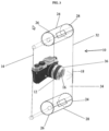
FIG. 3 illustrates one embodiment of a sensor shield; -
FIG. 4 illustrates another embodiment of a sensor shield; and -
FIG. 5 illustrates a further embodiment of a sensor shield. - The following detailed description is a contemplated mode of carrying out a sensor shield and process described herein. Although the sensor shield process is explained in relation to illustrated embodiments, it is to be understood that many other possible modifications and variations can be made without departing from the spirit and scope of the disclosure. Therefore, a sensor shield may be used to protect various types of sensors including a camera, sonar, laser, radar, and a plurality of other sensors. These sensors may be used to scan and to record information from an external environment and/or an internal environment of stationary or non-stationary vehicle such as a truck, an aircraft, a boat, a train and the like, or in a stationary environment such as on a wall, a seating arrangement in a public area, a hallway, an entryway, and in any environment where a sensor can be used for detecting and identifying environmental conditions.
- It is understood that the term vehicle as described herein includes an electric vehicle, a truck, a passenger vehicle, a hybrid vehicle, a sport utility vehicle, a bus, a water vehicle, a commercial vehicle, a fuel-driven vehicle and the like.
- It is further understood that a
sensor shield 10 and method of use thereof may be a part of an external vehicle monitoring system which can be in wireless communication with asensor 12 on avehicle 14. For example,FIGS. 1 and2 are flow charts showing interoperability of thesensor shield 10 with a computer system, not shown for clarity, associated with thevehicle 14. Such a computer system can include external vehicle monitoring systems such as a command center, a truck monitoring station, a vehicle integrated computer system and the like that communicate wirelessly with thevehicle 14. -
FIG. 3 shows one embodiment of thesensor shield 10 for protecting thesensor 12 of thevehicle 14. Thesensor 12 of thevehicle 14 has aninput surface 16 and at least one sensor-maintenance unit 18 operatively attached to theinput surface 16. Thesensor 12 of thevehicle 14 communicates with the computer system of thevehicle 14. The computer system of thevehicle 14 is controllably connected with and controls the sensor-maintenance unit 18 of thevehicle 14 and thesensor shield 10. - In the illustrated embodiments, the
sensor shield 10 has at least a firstshield implementation device 22 and a secondshield implementation device 24, oppositely disposed adjacent thesensor 12. Both the firstshield implementation device 22 and the secondshield implementation device 24 have atop surface 26 and abottom surface 28 for receiving ashield source 32 located adjacent thebottom surface 28 of both the firstshield implementation device 22 and the secondshield implementation device 24. The firstshield implementation device 22 and the secondshield implementation device 24 can be rotatable devices such as a roller, a revolving cylinder, a spool holder, a carousel, a rotatable ring, a disk, a wheel and the like for engaging theshield source 32. Theshield source 32 can include a shield, a cover, a guard, and the like having a size and asurface 34 for covering theinput surface 16 of thesensor 12. - In one embodiment, the
shield source 32 is constructed of a flexible sheet of transparent material, such as a plastic or other material that can be coated to protect theinput surface 16 of thesensor 12 from a contaminant. The firstshield implementation device 22 and the secondshield implementation device 24 are mounted to thevehicle 14 and are provided adjacent aside 36 of thesensor 12. In the embodiments shown inFigs. 3 through 5 , the firstshield implementation device 22 and the secondshield implementation device 24 have an electrical connection with a motor and a motor driver that advance theshield source 32 in accordance with at least one advancement sequence. Both the firstshield implementation device 22 and the secondshield implementation device 24 have a controller configured to receive communication from the computer system of thevehicle 14. The computer system of thevehicle 14 is configured to send a command to thefirst implantation device 22 and the secondshield implementation device 24. At least one command from the computer system regulates advancement of theshield source 32 in accordance with detection of at least a first sensor surface condition and the sensor-maintenance unit 18 performing at least one sensor-maintenance sequence. With advancement of theshield source 32, thesensor 12 communicates with the computer system of thevehicle 14 to direct removal of theshield source 32 and the provision of anew shield source 32. - The
sensor 12 detects at least the first sensor surface condition and the computer system of thevehicle 14 enables the sensor-maintenance unit 18 to change the first sensor surface condition. The computer system of thevehicle 14 further enables the firstshield implementation device 22 and the secondshield implementation device 24 to advance theshield source 32 in response to first deployment of the sensor-maintenance unit 18 if the first sensor surface condition is outside of a specified range. A first sensor surface condition can include presence of a contaminant, such as salt, snow, dirt, dust, and other types of environmental contamination. The sensor-maintenance unit 18 can include a wiper, pressurized air or any commercially available sensor-maintenance unit that removes a contaminant from a sensor. The advancement sequence comprises the firstshield implementation device 22 receiving theshield source 32 in an undeployed. i.e. rolled, configuration and the secondshield implementation device 24 accommodating advanced portions of theshield source 32. - The motor driver regulates intermittent release of the
shield source 32 according to at least a first sensor surface condition. The motor driver establishes a reeling start and a reeling end of theshield source 32. The motor driver can immobilize theshield source 32 based on a signal from thesensor 12. Thesensor shield 10 thereby transmits information identifying location of theshield source 32 adjacent theinput surface 16 of the sensor. Theshield implementation device 22 and theshield implementation device 24 permit theshield source 32 to be balanced and to calibrate any imbalance of theshield source 32 through advancement of theshield source 32. - The
shield source 32 extends over thesensor 12 and is positioned to abut theinput surface 16 and to be frictionally fitted thereover to obstruct a contaminant from coming between thesensor 12 and theshield source 32 while allowing for movement of theshield source 32. This allows for decontamination, repair, maintenance, and/or replacement of theshield source 32. - Once deployed, the
shield source 32 operates as a second input surface for protecting theinput surface 14 of thesensor 12. This also improves performance of thesensor 12 by reducing performance degradation due to dirt, snow, salt, and other contaminants that are encountered by avehicle 14. - In a particular embodiment shown in
FIG. 4 , theshield source 32 comprises a plurality of equally partitioned segments 38 provided in a rolled up configuration on the firstshield implementation device 22 and the secondshield implementation device 24. Eachindividual shield source 32 of the plurality of equally partitioned segments 38 can be connected to opposing longitudinal edges for a rolling connection to theshield implementation device 22 and theshield implementation device 24 and for traversing thesensor 12. The opposing longitudinal edges can be constructed of a flexible sheet of transparent material and could function as retainer engaging thetop surface 26 of theshield implementation device 22 andbottom surface 28 of theshield implementation device 24. An individual segment of the plurality of equally partitioned segments 38 can provide frictional engagement with thetop surface 26 of theshield implementation device 22 andbottom surface 28 of theshield implementation device 24 to continuously sustain a holding and rotatable state therebetween. Theshield implementation device 22 and theshield implementation device 24 can advance the plurality of equally partitioned segments 38 consecutively across thesensor 12. At least one command of the computer system regulates advancement of each of the plurality of equally partitioned segments 38 in accordance with performance data of thesensor 12. The computer system can identify advancement of all of the plurality of equally partitioned segments 38. Eachindividual shield source 32 of the plurality of equally partitioned segments 3 8can be removed, replaced, cleaned and reused. The plurality of equally partitioned segments 38 can comprise a plurality of shapes, sizes, and thickness to facilitate proper maintenance and/or operation of thesensor 12. - In a further embodiment shown in
FIG. 4 , theshield implementation device 22 and theshield implementation device 24 may be located adjacent two opposingsides 36 of thesensor 12. Theshield source 32 is included on the firstshield implementation device 22 and the secondshield implementation device 24 in a conveyor belt configuration. Therefore in this embodiment, theshield source 32 is rotatable about thesides 36 of thesensor 12 depending on position of theshield implementation device 22 andshield implementation device 24. This shield implementation device arrangement can include support an element, a magnet, a belt and the like at a position adjacent thetop surfaces 26 and the bottom surfaces 28 of theshield implementation device 22 and theshield implementation devices 24 to hold theshield source 32 in place during and after deployment.
Claims (5)
- A sensor shield for protecting a sensor of a vehicle, the sensor shield comprising:at least one sensor-maintenance unit operatively attached to the input surface of the sensor;a first shield implementation device having a top surface and a bottom surface and a second shield implementation device having a top surface and a bottom surface, the first shield implementation device and the second shield implementation device oppositely disposed adjacent the sensor; anda shield source located adj acent the bottom surface of both the first shield implementation device and the second shield implementation device, the shield source having a surface that covers the input surface of the sensor.
- The sensor shield defined in claim 1 wherein the first shield implementation device receives the shield source in a rolled configuration.
- The sensor shield defined in claim 1 wherein the shield source is included on the first shield implementation device and the second shield implementation device in a conveyor belt configuration.
- The sensor shield defined in claim 1 wherein the shield source comprises a plurality of segments.
- The sensor shield defined in claim 4 wherein the segments are equally partitioned.
Applications Claiming Priority (1)
| Application Number | Priority Date | Filing Date | Title |
|---|---|---|---|
| US17/692,615 US12235387B2 (en) | 2022-03-11 | 2022-03-11 | Sensor shield and method |
Publications (1)
| Publication Number | Publication Date |
|---|---|
| EP4242071A1 true EP4242071A1 (en) | 2023-09-13 |
Family
ID=85556794
Family Applications (1)
| Application Number | Title | Priority Date | Filing Date |
|---|---|---|---|
| EP23160952.0A Withdrawn EP4242071A1 (en) | 2022-03-11 | 2023-03-09 | Sensor shield and method |
Country Status (5)
| Country | Link |
|---|---|
| US (1) | US12235387B2 (en) |
| EP (1) | EP4242071A1 (en) |
| CN (1) | CN116729267A (en) |
| CA (1) | CA3188001A1 (en) |
| MX (1) | MX2023002784A (en) |
Citations (8)
| Publication number | Priority date | Publication date | Assignee | Title |
|---|---|---|---|---|
| DE2926768A1 (en) * | 1979-07-03 | 1981-01-15 | Messerschmitt Boelkow Blohm | Protection system keeping windows in optical devices clean - by moving transparent foil across when deemed necessary by opto-electronic detector |
| EP0648044A1 (en) * | 1993-10-06 | 1995-04-12 | Irén Dornier | Video camera with cleaning device |
| JP4756986B2 (en) * | 2005-10-14 | 2011-08-24 | オリンパスメディカルシステムズ株式会社 | Endoscope sheath and endoscope device |
| US20120238818A1 (en) * | 2011-02-09 | 2012-09-20 | O'prey Cormac | Covering Apparatus For An Endoscope Lens |
| EP2669123A1 (en) * | 2012-05-31 | 2013-12-04 | Nissan Motor Manufacturing (UK) Ltd. | Cleaning apparatus |
| US20150298657A1 (en) * | 2012-12-04 | 2015-10-22 | Robert Bosch Gmbh | method and device for controlling a cleaning apparatus for a vehicle camera, method for cleaning a vehicle camera and camera system for a vehicle |
| DE102017221496A1 (en) * | 2017-11-30 | 2019-06-06 | Robert Bosch Gmbh | Device designed for environment detection |
| US20210227113A1 (en) * | 2020-01-20 | 2021-07-22 | Monomer Software LLC | Optical device field of view cleaning apparatus |
Family Cites Families (10)
| Publication number | Priority date | Publication date | Assignee | Title |
|---|---|---|---|---|
| US7291047B1 (en) * | 2005-08-01 | 2007-11-06 | Roy Jones | Protective casing for water craft propellers |
| US9356061B2 (en) * | 2013-08-05 | 2016-05-31 | Apple Inc. | Image sensor with buried light shield and vertical gate |
| DE102014118220A1 (en) * | 2014-12-09 | 2016-06-09 | Huf Hülsbeck & Fürst Gmbh & Co. Kg | Camera arrangement of a motor vehicle |
| CN208984116U (en) | 2018-01-08 | 2019-06-14 | 飞利浦照明控股有限公司 | stand-alone sensor |
| DE102018109884B4 (en) * | 2018-04-24 | 2023-07-27 | Webasto SE | Sensor arrangement with screen element and method for producing the screen element |
| DE102018115581A1 (en) * | 2018-06-28 | 2020-01-02 | Huf Hülsbeck & Fürst Gmbh & Co. Kg | Sensor device for a vehicle |
| FR3086767B1 (en) * | 2018-09-27 | 2020-10-23 | Valeo Systemes Dessuyage | PROTECTION KIT FOR AN OPTICAL SENSOR OF A DRIVING ASSISTANCE SYSTEM FOR MOTOR VEHICLES INCLUDING A HEATING ELEMENT |
| CN109204161A (en) * | 2018-11-16 | 2019-01-15 | 铜仁学院 | Car reversing image pickup device and vehicle |
| US11650415B2 (en) * | 2019-12-16 | 2023-05-16 | Plusai, Inc. | System and method for a sensor protection mechanism |
| US11947011B2 (en) * | 2020-08-31 | 2024-04-02 | Ford Global Technologies, Llc | Sensor apparatus with cleaning |
-
2022
- 2022-03-11 US US17/692,615 patent/US12235387B2/en active Active
-
2023
- 2023-01-24 CA CA3188001A patent/CA3188001A1/en active Pending
- 2023-03-07 MX MX2023002784A patent/MX2023002784A/en unknown
- 2023-03-09 CN CN202310225182.1A patent/CN116729267A/en active Pending
- 2023-03-09 EP EP23160952.0A patent/EP4242071A1/en not_active Withdrawn
Patent Citations (8)
| Publication number | Priority date | Publication date | Assignee | Title |
|---|---|---|---|---|
| DE2926768A1 (en) * | 1979-07-03 | 1981-01-15 | Messerschmitt Boelkow Blohm | Protection system keeping windows in optical devices clean - by moving transparent foil across when deemed necessary by opto-electronic detector |
| EP0648044A1 (en) * | 1993-10-06 | 1995-04-12 | Irén Dornier | Video camera with cleaning device |
| JP4756986B2 (en) * | 2005-10-14 | 2011-08-24 | オリンパスメディカルシステムズ株式会社 | Endoscope sheath and endoscope device |
| US20120238818A1 (en) * | 2011-02-09 | 2012-09-20 | O'prey Cormac | Covering Apparatus For An Endoscope Lens |
| EP2669123A1 (en) * | 2012-05-31 | 2013-12-04 | Nissan Motor Manufacturing (UK) Ltd. | Cleaning apparatus |
| US20150298657A1 (en) * | 2012-12-04 | 2015-10-22 | Robert Bosch Gmbh | method and device for controlling a cleaning apparatus for a vehicle camera, method for cleaning a vehicle camera and camera system for a vehicle |
| DE102017221496A1 (en) * | 2017-11-30 | 2019-06-06 | Robert Bosch Gmbh | Device designed for environment detection |
| US20210227113A1 (en) * | 2020-01-20 | 2021-07-22 | Monomer Software LLC | Optical device field of view cleaning apparatus |
Also Published As
| Publication number | Publication date |
|---|---|
| US20230288534A1 (en) | 2023-09-14 |
| CA3188001A1 (en) | 2023-09-11 |
| MX2023002784A (en) | 2023-09-12 |
| US12235387B2 (en) | 2025-02-25 |
| CN116729267A (en) | 2023-09-12 |
Similar Documents
| Publication | Publication Date | Title |
|---|---|---|
| US10421439B2 (en) | Contamination prevention of vehicle cameras and sensors | |
| CN112977273B (en) | System and method for sensor protection system | |
| JP6245206B2 (en) | VEHICLE CONTROL DEVICE, VEHICLE CONTROL PROGRAM, AND VEHICLE | |
| US11279324B2 (en) | Rotary wiper system | |
| US11662231B2 (en) | System and method for a sensor protection assembly | |
| US11752631B2 (en) | Fleet inspection and maintenance mobile robot | |
| US20210185207A1 (en) | System and method for sensor system against glare and control thereof | |
| US20170329307A1 (en) | Robot system for asset health management | |
| US11318916B2 (en) | Vehicle maintenance | |
| US11754689B2 (en) | System and method for detecting sensor adjustment need | |
| US20210181502A1 (en) | System and method for a sensor protection mechanism | |
| US20210183179A1 (en) | System and method for anti-tampering sensor assembly | |
| CN113195317A (en) | Non-contact cleaning system | |
| US20210086644A1 (en) | Method for producing an electrical connection of a vehicle contact unit, vehicle connection device, and vehicle | |
| US20180319376A1 (en) | System And Method For Automated Cleaning Of A Sensor Lens | |
| US12235387B2 (en) | Sensor shield and method | |
| CN114206690A (en) | System and method for cleaning sensors of a vehicle | |
| KR20190033844A (en) | Attachment system and method of weather strip | |
| GB2572478A (en) | Sensor cleaner | |
| US10899246B1 (en) | Method and apparatus for localization of vehicle side electrical charger units | |
| US9475466B2 (en) | Navigation-linked vehicle de-icer or debris-remover control | |
| CN114924569B (en) | AGV car body path planning system for artificial diamond synthesis | |
| US20230184898A1 (en) | Sensor protection device and control system thereof | |
| JP2009048639A (en) | Travel recording device for automobile | |
| CN214122026U (en) | Longitudinal tearing detection device for conveying belt |
Legal Events
| Date | Code | Title | Description |
|---|---|---|---|
| PUAI | Public reference made under article 153(3) epc to a published international application that has entered the european phase |
Free format text: ORIGINAL CODE: 0009012 |
|
| STAA | Information on the status of an ep patent application or granted ep patent |
Free format text: STATUS: REQUEST FOR EXAMINATION WAS MADE |
|
| 17P | Request for examination filed |
Effective date: 20230309 |
|
| AK | Designated contracting states |
Kind code of ref document: A1 Designated state(s): AL AT BE BG CH CY CZ DE DK EE ES FI FR GB GR HR HU IE IS IT LI LT LU LV MC ME MK MT NL NO PL PT RO RS SE SI SK SM TR |
|
| STAA | Information on the status of an ep patent application or granted ep patent |
Free format text: STATUS: EXAMINATION IS IN PROGRESS |
|
| STAA | Information on the status of an ep patent application or granted ep patent |
Free format text: STATUS: THE APPLICATION HAS BEEN WITHDRAWN |
|
| 17Q | First examination report despatched |
Effective date: 20250916 |
|
| 18W | Application withdrawn |
Effective date: 20250930 |