EP4241966A1 - Apparatus for folding pouch - Google Patents
Apparatus for folding pouch Download PDFInfo
- Publication number
- EP4241966A1 EP4241966A1 EP21889559.7A EP21889559A EP4241966A1 EP 4241966 A1 EP4241966 A1 EP 4241966A1 EP 21889559 A EP21889559 A EP 21889559A EP 4241966 A1 EP4241966 A1 EP 4241966A1
- Authority
- EP
- European Patent Office
- Prior art keywords
- protrusion
- cup
- guide
- close contact
- cup part
- Prior art date
- Legal status (The legal status is an assumption and is not a legal conclusion. Google has not performed a legal analysis and makes no representation as to the accuracy of the status listed.)
- Granted
Links
Images




Classifications
-
- B—PERFORMING OPERATIONS; TRANSPORTING
- B29—WORKING OF PLASTICS; WORKING OF SUBSTANCES IN A PLASTIC STATE IN GENERAL
- B29C—SHAPING OR JOINING OF PLASTICS; SHAPING OF MATERIAL IN A PLASTIC STATE, NOT OTHERWISE PROVIDED FOR; AFTER-TREATMENT OF THE SHAPED PRODUCTS, e.g. REPAIRING
- B29C53/00—Shaping by bending, folding, twisting, straightening or flattening; Apparatus therefor
- B29C53/36—Bending and joining, e.g. for making hollow articles
-
- H—ELECTRICITY
- H01—ELECTRIC ELEMENTS
- H01M—PROCESSES OR MEANS, e.g. BATTERIES, FOR THE DIRECT CONVERSION OF CHEMICAL ENERGY INTO ELECTRICAL ENERGY
- H01M10/00—Secondary cells; Manufacture thereof
- H01M10/04—Construction or manufacture in general
- H01M10/0404—Machines for assembling batteries
-
- B—PERFORMING OPERATIONS; TRANSPORTING
- B29—WORKING OF PLASTICS; WORKING OF SUBSTANCES IN A PLASTIC STATE IN GENERAL
- B29C—SHAPING OR JOINING OF PLASTICS; SHAPING OF MATERIAL IN A PLASTIC STATE, NOT OTHERWISE PROVIDED FOR; AFTER-TREATMENT OF THE SHAPED PRODUCTS, e.g. REPAIRING
- B29C53/00—Shaping by bending, folding, twisting, straightening or flattening; Apparatus therefor
- B29C53/02—Bending or folding
- B29C53/04—Bending or folding of plates or sheets
- B29C53/06—Forming folding lines by pressing or scoring
- B29C53/063—Forming folding lines by pressing or scoring combined with folding
-
- H—ELECTRICITY
- H01—ELECTRIC ELEMENTS
- H01M—PROCESSES OR MEANS, e.g. BATTERIES, FOR THE DIRECT CONVERSION OF CHEMICAL ENERGY INTO ELECTRICAL ENERGY
- H01M50/00—Constructional details or processes of manufacture of the non-active parts of electrochemical cells other than fuel cells, e.g. hybrid cells
- H01M50/10—Primary casings; Jackets or wrappings
- H01M50/102—Primary casings; Jackets or wrappings characterised by their shape or physical structure
- H01M50/105—Pouches or flexible bags
-
- H—ELECTRICITY
- H01—ELECTRIC ELEMENTS
- H01M—PROCESSES OR MEANS, e.g. BATTERIES, FOR THE DIRECT CONVERSION OF CHEMICAL ENERGY INTO ELECTRICAL ENERGY
- H01M50/00—Constructional details or processes of manufacture of the non-active parts of electrochemical cells other than fuel cells, e.g. hybrid cells
- H01M50/10—Primary casings; Jackets or wrappings
- H01M50/116—Primary casings; Jackets or wrappings characterised by the material
-
- B—PERFORMING OPERATIONS; TRANSPORTING
- B29—WORKING OF PLASTICS; WORKING OF SUBSTANCES IN A PLASTIC STATE IN GENERAL
- B29L—INDEXING SCHEME ASSOCIATED WITH SUBCLASS B29C, RELATING TO PARTICULAR ARTICLES
- B29L2031/00—Other particular articles
-
- B—PERFORMING OPERATIONS; TRANSPORTING
- B29—WORKING OF PLASTICS; WORKING OF SUBSTANCES IN A PLASTIC STATE IN GENERAL
- B29L—INDEXING SCHEME ASSOCIATED WITH SUBCLASS B29C, RELATING TO PARTICULAR ARTICLES
- B29L2031/00—Other particular articles
- B29L2031/34—Electrical apparatus, e.g. sparking plugs or parts thereof
- B29L2031/3468—Batteries, accumulators or fuel cells
-
- Y—GENERAL TAGGING OF NEW TECHNOLOGICAL DEVELOPMENTS; GENERAL TAGGING OF CROSS-SECTIONAL TECHNOLOGIES SPANNING OVER SEVERAL SECTIONS OF THE IPC; TECHNICAL SUBJECTS COVERED BY FORMER USPC CROSS-REFERENCE ART COLLECTIONS [XRACs] AND DIGESTS
- Y02—TECHNOLOGIES OR APPLICATIONS FOR MITIGATION OR ADAPTATION AGAINST CLIMATE CHANGE
- Y02E—REDUCTION OF GREENHOUSE GAS [GHG] EMISSIONS, RELATED TO ENERGY GENERATION, TRANSMISSION OR DISTRIBUTION
- Y02E60/00—Enabling technologies; Technologies with a potential or indirect contribution to GHG emissions mitigation
- Y02E60/10—Energy storage using batteries
Definitions
- the present invention relates to a device for folding a pouch having a first cup part and a second cup part to accommodate an electrode assembly, and more particularly, to a device for folding a pouch, which more efficiently supports a portion to be folded between a first cup part and a second cup part to facilitate accurate folding in selected portions.
- types of secondary batteries include a nickel-cadmium battery, a nickel-hydrogen battery, a lithium-ion battery, a lithium-ion polymer battery and so on.
- Such secondary batteries have been applied to and used in not only small products such as digital camera, P-DVD, MP3P, mobile phone, PDA, portable game device, power tool and E-bike, but also large products, such as electric vehicle and hybrid vehicle, which require higher powers, energy storage devices for storing surplus electricity or new renewable energy, and energy storage devices for backup.
- a positive electrode collector and a negative electrode collector are coated with electrode active material slurry to make a positive electrode and a negative electrode, and then the positive electrode and the negative electrode are stacked alternately with a separator therebetween to form an electrode assembly having a predetermined shape.
- a battery case accommodates the electrode assembly and is sealed after injection of an electrolyte to manufacture the secondary battery.
- the secondary batteries are classified into a pouch type, a can type, etc., according to a material of the case for accommodating the electrode assembly.
- a pouch type secondary battery is manufactured so that an electrode assembly is accommodated and sealed in a pouch made of a flexible polymer material, and a can type secondary battery is manufactured so that an electrode assembly is accommodated in a case made of a material such as metal or plastic.
- the pouch to be provided as a case of the pouch type secondary battery is manufactured so that one or two cup parts are formed by press processing of a pouch film having flexibility. After the cup part is formed, an accommodation space of the cup part accommodates an electrode assembly, and a circumferential part of a side thereof is sealed to manufacture the secondary battery.
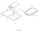
- a material of the pouch 10 is modified by press to form a first cup part 1 and a second cup part 2, each of which is formed in a concave shape to have a predetermined size of a space formed therein, and unpressed parts form a first circumferential part 1a and a second circumferential part 2a along circumferences.
- the second cup part 2 is folded along a connection part 3 that is a portion folded between the first cup part 1 and the second cup part 2, and the first circumferential part 1a and the second circumferential part 2a are in contact with each other. Thereafter, heat and pressure are applied to the first circumferential part 1a and the second circumferential part 2a in contact with each other, followed by sealing.
- a conventional folding device has a structure in which an upper nest 40 and a lower nest 30 are coupled through a guide 50 (50a and 50b), and one side part 50b of the guide is coupled to the upper nest 40 and another side part 50a is coupled to the lower nest 30.
- the guide 50 has a structure in which a support protrusion 51 protrudes to support a bottom surface of a connection part 3.
- One side part 51b of the support protrusion 51 protrudes from the one side part 50b of the guide, and another side part 51a protrudes from the other side part 50a of the guide.
- connection part 3 is folded so that the second cup part 2 is placed on the first cup part 1 as illustrated in FIG. 1b .
- connection part 3 is separated from the support protrusion 51 during rotation of the upper nest 40 and is thus incompletely folded.
- the connection part 3 since there might be a difference in separation occurrence rate, etc. according to flexibility, strength, etc. of the pouch 10, there has been a problem that the consistent folding quality is difficult to secure.
- a main object of the present invention is to provide a device for folding a pouch, which is capable of solving the problem of incomplete folding caused by separation of a connection part from a support protrusion.
- a device for folding a pouch which has a first cup part and a second cup part, each having a concavely recessed shape to accommodate an electrode assembly, and in which a first circumferential part is formed flat along a circumference of the first cup part and a second circumferential part is formed flat along a circumference of the second cup part, includes: a lower nest on which the first cup part is seated; an upper nest on which the second cup part is seated; a guide provided with a first guide fixed to the lower nest and having a first protrusion protruding upwardly therefrom, and a second guide fixed to the upper nest and having a second protrusion protruding upwardly therefrom, the first protrusion and the second protrusion which protrude from the first guide and the second guide being in close contact with each other to form a support protrusion; and a pressing part that allows a connection part of the first circumferential part and the second circumferential part to be in close contact with the
- the lower nest and the upper nest may be horizontal.
- the first protrusion may protrude from the first guide
- the second protrusion may protrude from the second guide
- the first protrusion and the second protrusion may be in close contact with each other to form the support protrusion, wherein, when the upper nest rotates, the first protrusion and the second protrusion in close contact with each other may be separated to be spread apart from each other.
- the first protrusion may be formed integrally with the first guide, and the second protrusion may be formed integrally with the second guide.
- the first protrusion and the second protrusion may respectively define, as slopes, surfaces in contact with the first cup part and the second cup part so that the support protrusion has a cross-sectional shape getting sharper towards an end.
- a first corner formed between surfaces that are perpendicular to each other as the first protrusion protrudes from the first guide, and a second corner formed between surfaces that are perpendicular to each other as the second protrusion protrudes from the second guide, may be formed to be curved surfaces.
- the pressing part may include a body part that allows the connection part of the first circumferential part and the second circumferential part to be in close contact with the support protrusion and an extension part that extends from the body part and allows a sidewall surface of the first cup part to be in close contact with the first protrusion when the body part presses the connection part.
- a seating groove may be formed between the extension part and the body part so that an upper end of the support protrusion is seated thereon.
- a first corner may be formed between surfaces that are perpendicular to each other as the first protrusion protrudes from the first guide, and when the body part of the pressing part allows the connection part to be in close contact with the support protrusion, the extension part may allow the first cup part to be in close contact with the first corner.
- the pressing part may be configured so that an end protrudes from the extension part to such an extent that when the extension part is in close contact with the first protrusion, the body part is in contact only with the first protrusion and not in contact with the second protrusion.
- the pouch may be manufactured by stacking an inner layer made of a polymer; an outer layer made of a different type of a polymer from the inner layer; and a metal layer stacked between the inner layer and an outer layer and made of an aluminum material.
- a device for folding a pouch provided in the present invention may include a guide in which a second guide is omitted and a first guide is included alone.
- the device for folding the pouch according to the present invention may include a lower nest, an upper nest, and a pressing part, and the guide may be included in a configuration fixed to the lower nest and having a support protrusion protruding upwardly.
- the present invention having the technical features as above may prevent the separation phenomenon of the connection part because the pressing part allows the connection part to be in close contact with the support protrusion during the rotation of the upper nest.
- the first protrusion and the second protrusion respectively define, as slopes, surfaces in contact with the first cup part and the second cup part so that the support protrusion has the cross-sectional shape getting sharper towards the end thereof. Accordingly, the first protrusion and the second protrusion may be brought into closer contact with the outside surfaces of the first cup part and the second cup part.
- the pressing part may include the body part that allow the connection part of the first circumferential part and the second circumferential part to be in close contact with the support protrusion and the extension part that extends from the body part and allows the sidewall surface of the first cup part to be in close contact with the first protrusion when the body part presses the connection part. Accordingly, the wider portion (e.g., the inner surface of the first cup part) is brought into close contact with the support protrusion, and thus the connection part may be more stably supported on the support protrusion during the folding.
- the seating groove may be formed between the extension part and the body part so that the upper end of the support protrusion is seated thereon. Accordingly, the pressing part may be stably supported on the support protrusion.
- the first corner may be formed between the surfaces that are perpendicular to each other as the first protrusion protrudes from the first guide, and when the body part of the pressing part allows the connection part to be in close contact with the support protrusion, the extension part may allow the first cup part to be in close contact with the first corner. Accordingly, the separation of the pressing part may be prevented, and the deformation of the first cup part may be prevented.
- the present invention relates to a device for folding a pouch 10 which has a first cup part 1 and a second cup part 2, each having a concave shape to accommodate an electrode assembly, and in which a first circumferential part 1a is formed flat along a circumference of the first cup part 1, and a second circumferential part 2a is formed flat along a circumference of the second cup part 2.
- a device for folding the pouch according to the present invention will be described in more detail with reference to the accompanying drawings.
- a folding device includes a lower nest 30, an upper nest 40, a guide 50 and a pressing part 60.
- the lower nest 30 is sized to have the first cup part 1 of the pouch 10 seated thereon, and defines a seating surface as a flat surface.
- the upper nest 40 is sized to have the second cup part 2 of the pouch 10 seated thereon, and defines a seating surface as a flat surface.
- the guide 50 includes a first guide 50a and a second guide 50b.
- the first guide 50a has a structure fixed to one side (i.e., one side facing the upper nest) of the lower nest 40 and having a first protrusion 51a protruding upwardly therefrom.
- the second guide 50b is fixed to one side (i.e., one side facing the lower nest) of the upper nest 40 and has a second protrusion 51b protruding upwardly therefrom.
- the first guide 50a and the second guide 50b are in close contact with each other.
- the first guide 50a and the second guide 50b may be spread apart.
- the first guide 50a and the second guide 50b can be in close contact with and separated from each other (being separated herein means being spread apart so that an angle formed therebetween increases as illustrated in FIG. 2 ).
- the first protrusion 51a and the second protrusion 51b form the support protrusion 51 in a state in close contact with each other.
- the pressing part 60 further provided in the present invention approaches a connection part 3 of the first circumferential part 1a and the second circumferential part 2a to allow the connection part 3 to be in close contact with the support protrusion 51 when the first cup part 1 and the second cup part 2 are seated on the lower nest 30 and the upper nest 40, respectively.
- the upper nest 40 starts to rotate so that the second cup part 2 is folded onto the first cup part 1.
- the pressing part 60 is separated before the upper nest 40 is in contact with the pressing part 60.
- the upper nest 40 rotates upwardly until being parallel with the lower nest 30.
- the first guide 50a and the second guide 50b provided in the present invention are in horizontal contact with each other, the lower nest 30 and the upper nest 40 are horizontal.
- the first guide 50a is formed integrally to have the first protrusion 51a protruding therefrom
- the second guide 50b is formed integrally to have the second protrusion 51b protruding therefrom. Accordingly, the first protrusion 51a and the second protrusion 51b are brought into close contact with each other to form the support protrusion 51.
- the first protrusion 51a and the second protrusion 51b in close contact with each other are separated to be spread apart from each other.
- the first protrusion 51a and the second protrusion 51b in close contact with each other being separated to be spread apart from each other means that the second protrusion 51b is separated to be spread apart from the first protrusion 51a while rotating with the rotation of the upper nest 40, and in particular, may mean that the second protrusion 51b rotates about end portions, serving as a center of rotation, protruding from the first protrusion 51a and the second protrusion 51b, and accordingly is separated so that an angle between the first protrusion 51a and the second protrusion 51b increases.
- the pressing part 60 provided in the present invention may include only a body part 61 having a shape getting sharper towards an end, and may further include an extension part 62 extending from the body part 61.
- FIG. 3 illustrating configurations in which the pouch 10 is being folded in a state where the pressing part 60 having an extension part 62 formed therein supports the connection part 3
- FIG. 4 illustrating the configuration in which a pressing part 60 having an extension part 62 formed therein is in contact with the support protrusion 51
- FIG. 3 illustrating configurations in which the pouch 10 is being folded in a state where the pressing part 60 having an extension part 62 formed therein supports the connection part 3
- FIG. 4 illustrating the configuration in which a pressing part 60 having an extension part 62 formed therein is in contact with the support protrusion 51
- the pressing part 60 provided in the present invention includes a body part 61 that allows a connection part 3 of a first circumferential part 1a and a second circumferential part 2a to be in close contact with a support protrusion 51 and the extension part 62 that extends along one side of the body part 61 so that the area become larger, and allows a sidewall surface of a first cup part 1 to be in close contact with a first protrusion 51a when the body part 61 presses the connection part 3.
- the extension part 62 allows an inner surface of the first cup part 1 to be in close contact with a side surface of the support protrusion 51 when the body part 61 allows the connection part 3 to be in close contact with the support protrusion 51. Accordingly, the likelihood of separation that may occur in the first cup part 1 may be further decreased.
- a seating groove 63 is formed between the extension part 62 and the body part 61 so that an upper end of the support protrusion 51 is seated thereon.
- the extension groove 63 enables the pressing part 60 to be seated on the support protrusion 51 so that the extension part 62 may be held on the support protrusion 51 when the body part 61 supports the connection part 3. Accordingly, the pressing part 60 may be more stably kept in a fixed position.
- the first protrusion 51a and the second protrusion 51b respectively define, as slopes, surfaces in contact with the first cup part 1 and the second cup part 2 so that the support protrusion 51 has a cross-sectional shape getting sharper towards an end.
- the first cup part 1 and the second cup part 2 are cooled and contracted to have a configuration in which a slight upward slope is formed, not a fully perpendicular configuration. Accordingly, the first protrusion 51a and the second protrusion 51b define, as slopes, surfaces in contact with the first cup part 1 and the second cup part 2 so as to be in close contact with outer surfaces of the first cup part 1 and the second cup part 2 to avoid an occurrence of an unnecessary gap.
- corner portions of the first cup part 1 and the second cup part 2 have a structure rounded with a predetermined curvature. Accordingly, in order for the support protrusion 51 to be in close contact with the rounded portions of the first cup part 1 and the second cup part 2, a first corner 52a formed between surfaces that are perpendicular to each other as the first protrusion 51a protrudes from the first guide 50a, and a second corner 52b formed between surfaces that are perpendicular to each other as the second protrusion 51b protrudes from the second guide 50b, are formed to be curved surfaces.
- the extension part 62 may have an extending structure to allow the first cup part 1 to be in close contact with the first corner 52a when the body part 61 of the pressing part allows the connection part 3 to be in close contact with the support protrusion 51.
- the pouch 10 provided in the present invention may have a structure in which an inner layer made of a polymer, an outer layer made of a different type of a polymer from the inner layer, and a metal layer stacked between the inner layer and an outer layer and made of an aluminum material, are stacked, and be manufactured so that the inner layer constitutes a sealant layer, and the outer layer constitutes a drawing assistance layer and a surface protection layer, and the metal layer constitutes a moisture barrier layer.
- the sealant layer formed by the inner layer may be made of a polymer and formed as an innermost layer to be in direct contact with an electrode assembly. Since the sealant layer is in direct contact with the electrode assembly, the sealant layer has insulating nature and corrosion resistance against an electrolyte. Since the inside needs to be completely sealed to block material movement between the inside and the outside, the sealant layer has high sealability.
- Such a sealant layer may be made of at least one material selected from the group consisting of polyethylene, polypropylene, polycarbonate, polyethylene terephthalate, polyvinyl chloride, acryl-based polymer, polyacrylonitrile, polyimide, polyamide, cellulose, aramid, nylon, polyester, poly(p-phenylene benzobisoxazole), polyarylate, Teflon, and glass fiber.
- the moisture barrier layer formed by the metal layer provides functions of securing the mechanical strength of the pouch 10, blocking entry and exit of gas, moisture, etc. outside the pouch 10, and preventing leakage of an electrolyte.
- the surface protection layer included in the outer layer is formed as an outermost layer to protect the pouch 10 from friction and collision with the exterior and to electrically insulate an electrode assembly from the outside.
- the drawing assistance layer which may be included in the outer layer is located between the surface protection layer and the moisture barrier layer and provides a function of preventing the surface protection layer and the moisture barrier layer from being detached when drawn.
- the present invention having the technical features as above may prevent a separation phenomenon of the connection part 3, since the pressing part 60 allows the connection part 3 to be in close contact with the support protrusion 51 during rotation of the upper nest 40.
- the first protrusion 51a and the second protrusion 51b respectively define, as slopes, surfaces in contact with the first cup part 1 and the second cup part 2 so that the support protrusion 51 has a cross-sectional shape getting sharper towards an end. Accordingly, the first protrusion 51a and the second protrusion 51b may be brought into closer contact with outside surfaces of the first cup part 1 and the second cup part 2.
- the protrusion length of the body part 61 of the pressing part 60 may be restricted so that an interference to rotation of the second cup part 2 does not occur when the connection part 3 is in close with the support protrusion 51.
- the pressing part 60 may be formed a litter shorter than the embodiment described above so as to prevent occurrence of interference to folding of the connection part 3 according to the thickness or material of a pouch and to enable adjustment of a portion at which the connection part 3 starts to be bent.
- the pressing part 60 may be provided in a structure where the length of an end protruding from the extension part 62 is restricted to such an extent that when the extension part 62 is in close contact with the first protrusion 51a, the body part 61 is in contact only with the first protrusion 51a and not in contact with the second protrusion 51b.
- a device for folding a pouch provided in the present invention may include a guide in which a second guide 50b is omitted and a first guide 50a is included alone.
- the pressing part 60 may press the connection part 3 on a surface of the first protrusion 51a during rotation of the second cup part 2, and thus the second guide 50b may be omitted.
- the first protrusion 51a may protrude only from the first guide 50a and have a shape of a combination with the second protrusion 51b.
- the device for folding the pouch in which the second guide 50b is omitted includes a lower nest on which the first cup part is seated, an upper nest on which the second cup part is seated therein, and a pressing part that allows a connection part of a first circumferential part and a second circumferential part to be in close contact with a support protrusion when the first cup part and the second cup part are seated on the lower nest and the upper nest, respectively.
- the guide may be included in a configuration consisting only of a first guide, that is, in a structure where the guide is fixed to the lower nest and a first protrusion 51a protruding upwardly therefrom forms a support protrusion 51.
- a guide 50 may include a second guide 50b together with a first guide 50a, and be provided in a structure where a first protrusion 51a is formed only on the first guide 50a and a second protrusion 51b is not be formed on the second guide 50b.
- the pressing part 60 includes a body part 61 that allows a connection part 3 of a first circumferential part 1a and a second circumferential part 2a to be in close contact with a support protrusion 51 and an extension part 62 that extends from the body part 61 and allows a sidewall surface of a first cup part 1 to be in close contact with a first protrusion 51a when the body part 61 presses the connection part 3. Accordingly, a wider portion is brought into close contact with the support protrusion 51, and thus the connection part may be more stably supported during folding.
- a seating groove 63 is formed between the extension part 62 and the body part 61 so that an upper end of the support protrusion 51 is seated thereon. Accordingly, the pressing part 60 may be stably supported on the support protrusion 51.
- a first corner 52a is formed between surfaces that are perpendicular to each other as the first protrusion 51a protrudes from the first guide 50a, and when the body part 61 of the pressing part 60 allows the connection part 3 to be in close contact with the support protrusion, the extension part 62 allows the first cup part 1 to be in close contact with the first corner 52a. Accordingly, separation of the pressing part 60 may be prevented, and deformation of the first cup part 1 may be prevented.
Landscapes
- Chemical & Material Sciences (AREA)
- Chemical Kinetics & Catalysis (AREA)
- Electrochemistry (AREA)
- General Chemical & Material Sciences (AREA)
- Engineering & Computer Science (AREA)
- Mechanical Engineering (AREA)
- Manufacturing & Machinery (AREA)
- Packages (AREA)
- Making Paper Articles (AREA)
- Bag Frames (AREA)
- Auxiliary Devices For And Details Of Packaging Control (AREA)
- Table Devices Or Equipment (AREA)
Abstract
Description
- The present application claims the benefit of the priority of
Korean Patent Application Nos. 10-2020-0145441, filed on November 03, 2020 10-2021-0148732, filed on November 2, 2021 - The present invention relates to a device for folding a pouch having a first cup part and a second cup part to accommodate an electrode assembly, and more particularly, to a device for folding a pouch, which more efficiently supports a portion to be folded between a first cup part and a second cup part to facilitate accurate folding in selected portions.
- In general, types of secondary batteries include a nickel-cadmium battery, a nickel-hydrogen battery, a lithium-ion battery, a lithium-ion polymer battery and so on. Such secondary batteries have been applied to and used in not only small products such as digital camera, P-DVD, MP3P, mobile phone, PDA, portable game device, power tool and E-bike, but also large products, such as electric vehicle and hybrid vehicle, which require higher powers, energy storage devices for storing surplus electricity or new renewable energy, and energy storage devices for backup.
- In order to manufacture such a secondary battery, a positive electrode collector and a negative electrode collector are coated with electrode active material slurry to make a positive electrode and a negative electrode, and then the positive electrode and the negative electrode are stacked alternately with a separator therebetween to form an electrode assembly having a predetermined shape. Thereafter, a battery case accommodates the electrode assembly and is sealed after injection of an electrolyte to manufacture the secondary battery.
- The secondary batteries are classified into a pouch type, a can type, etc., according to a material of the case for accommodating the electrode assembly. A pouch type secondary battery is manufactured so that an electrode assembly is accommodated and sealed in a pouch made of a flexible polymer material, and a can type secondary battery is manufactured so that an electrode assembly is accommodated in a case made of a material such as metal or plastic.
- The pouch to be provided as a case of the pouch type secondary battery is manufactured so that one or two cup parts are formed by press processing of a pouch film having flexibility. After the cup part is formed, an accommodation space of the cup part accommodates an electrode assembly, and a circumferential part of a side thereof is sealed to manufacture the secondary battery.
- Referring to
FIG. 1a illustrating configurations before and after an electrode assembly is mounted in a pouch, a material of thepouch 10 is modified by press to form afirst cup part 1 and asecond cup part 2, each of which is formed in a concave shape to have a predetermined size of a space formed therein, and unpressed parts form a firstcircumferential part 1a and a secondcircumferential part 2a along circumferences. - In addition, when an electrode assembly 4 is mounted in the
first cup part 1, thesecond cup part 2 is folded along aconnection part 3 that is a portion folded between thefirst cup part 1 and thesecond cup part 2, and the firstcircumferential part 1a and the secondcircumferential part 2a are in contact with each other. Thereafter, heat and pressure are applied to the firstcircumferential part 1a and the secondcircumferential part 2a in contact with each other, followed by sealing. - Meanwhile, referring to
FIG. 1b illustrating configurations in which a pouch is being folded according to a conventional method, a conventional folding device has a structure in which anupper nest 40 and alower nest 30 are coupled through a guide 50 (50a and 50b), and oneside part 50b of the guide is coupled to theupper nest 40 and anotherside part 50a is coupled to thelower nest 30. In addition, theguide 50 has a structure in which asupport protrusion 51 protrudes to support a bottom surface of aconnection part 3. Oneside part 51b of thesupport protrusion 51 protrudes from the oneside part 50b of the guide, and anotherside part 51a protrudes from theother side part 50a of the guide. - In a state where the
first cup part 1, thesecond cup part 2 and theconnection part 3 are placed on thelower nest 30, theupper nest 40 and thesupport protrusion 51, when theupper nest 40 rotates, theconnection part 3 is folded so that thesecond cup part 2 is placed on thefirst cup part 1 as illustrated inFIG. 1b . - However, in such a conventional structure, there has been a case where the
connection part 3 is separated from thesupport protrusion 51 during rotation of theupper nest 40 and is thus incompletely folded. In particular, since there might be a difference in separation occurrence rate, etc. according to flexibility, strength, etc. of thepouch 10, there has been a problem that the consistent folding quality is difficult to secure. - Therefore, a main object of the present invention is to provide a device for folding a pouch, which is capable of solving the problem of incomplete folding caused by separation of a connection part from a support protrusion.
- According to the present invention for solving the problems as described above, a device for folding a pouch which has a first cup part and a second cup part, each having a concavely recessed shape to accommodate an electrode assembly, and in which a first circumferential part is formed flat along a circumference of the first cup part and a second circumferential part is formed flat along a circumference of the second cup part, includes: a lower nest on which the first cup part is seated; an upper nest on which the second cup part is seated; a guide provided with a first guide fixed to the lower nest and having a first protrusion protruding upwardly therefrom, and a second guide fixed to the upper nest and having a second protrusion protruding upwardly therefrom, the first protrusion and the second protrusion which protrude from the first guide and the second guide being in close contact with each other to form a support protrusion; and a pressing part that allows a connection part of the first circumferential part and the second circumferential part to be in close contact with the support protrusion when the first cup part and the second cup part are seated on the lower nest and the upper nest, respectively. In a state where the pressing part allows the connection part to be in close contact with the support protrusion, the upper nest rotates so that the second cup part is folded to be on the first cup part.
- When the first guide and the second guide are in horizontal contact with each other, the lower nest and the upper nest may be horizontal.
- The first protrusion may protrude from the first guide, the second protrusion may protrude from the second guide, and the first protrusion and the second protrusion may be in close contact with each other to form the support protrusion, wherein, when the upper nest rotates, the first protrusion and the second protrusion in close contact with each other may be separated to be spread apart from each other.
- The first protrusion may be formed integrally with the first guide, and the second protrusion may be formed integrally with the second guide.
- The first protrusion and the second protrusion may respectively define, as slopes, surfaces in contact with the first cup part and the second cup part so that the support protrusion has a cross-sectional shape getting sharper towards an end.
- A first corner formed between surfaces that are perpendicular to each other as the first protrusion protrudes from the first guide, and a second corner formed between surfaces that are perpendicular to each other as the second protrusion protrudes from the second guide, may be formed to be curved surfaces.
- The pressing part may include a body part that allows the connection part of the first circumferential part and the second circumferential part to be in close contact with the support protrusion and an extension part that extends from the body part and allows a sidewall surface of the first cup part to be in close contact with the first protrusion when the body part presses the connection part.
- A seating groove may be formed between the extension part and the body part so that an upper end of the support protrusion is seated thereon.
- A first corner may be formed between surfaces that are perpendicular to each other as the first protrusion protrudes from the first guide, and when the body part of the pressing part allows the connection part to be in close contact with the support protrusion, the extension part may allow the first cup part to be in close contact with the first corner.
- In addition, the pressing part may be configured so that an end protrudes from the extension part to such an extent that when the extension part is in close contact with the first protrusion, the body part is in contact only with the first protrusion and not in contact with the second protrusion.
- The pouch may be manufactured by stacking an inner layer made of a polymer; an outer layer made of a different type of a polymer from the inner layer; and a metal layer stacked between the inner layer and an outer layer and made of an aluminum material.
- Alternatively, a device for folding a pouch provided in the present invention may include a guide in which a second guide is omitted and a first guide is included alone.
- That is, the device for folding the pouch according to the present invention may include a lower nest, an upper nest, and a pressing part, and the guide may be included in a configuration fixed to the lower nest and having a support protrusion protruding upwardly.
- The present invention having the technical features as above may prevent the separation phenomenon of the connection part because the pressing part allows the connection part to be in close contact with the support protrusion during the rotation of the upper nest.
- The first protrusion and the second protrusion respectively define, as slopes, surfaces in contact with the first cup part and the second cup part so that the support protrusion has the cross-sectional shape getting sharper towards the end thereof. Accordingly, the first protrusion and the second protrusion may be brought into closer contact with the outside surfaces of the first cup part and the second cup part.
- The pressing part may include the body part that allow the connection part of the first circumferential part and the second circumferential part to be in close contact with the support protrusion and the extension part that extends from the body part and allows the sidewall surface of the first cup part to be in close contact with the first protrusion when the body part presses the connection part. Accordingly, the wider portion (e.g., the inner surface of the first cup part) is brought into close contact with the support protrusion, and thus the connection part may be more stably supported on the support protrusion during the folding.
- In addition, the seating groove may be formed between the extension part and the body part so that the upper end of the support protrusion is seated thereon. Accordingly, the pressing part may be stably supported on the support protrusion.
- Moreover, the first corner may be formed between the surfaces that are perpendicular to each other as the first protrusion protrudes from the first guide, and when the body part of the pressing part allows the connection part to be in close contact with the support protrusion, the extension part may allow the first cup part to be in close contact with the first corner. Accordingly, the separation of the pressing part may be prevented, and the deformation of the first cup part may be prevented.
-
-
FIG. 1a is a view illustrating configurations before and after an electrode assembly is mounted in a pouch. -
FIG. 1b is a view illustrating configurations in which a pouch is being folded by a method according to a related art. -
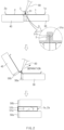
FIG. 2 is a view illustrating configurations in which a pouch is being folded in a state where a pressing part supports a connection part. -
FIG. 3 is a view illustrating configurations in which a pouch is being folded in a state where the pressing part having an extension part formed therein supports the connection part. -
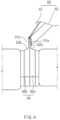
FIG. 4 is a view illustrating a configuration in which the pressing part having the extension part formed therein is in contact with the support protrusion. -
FIG. 5 is a view illustrating a configuration in which the pressing part having the extension part formed therein is spaced apart from the support protrusion. -
FIG. 6 is a view illustrating a configuration in which the extension part formed in the pressing part extends to a first corner. -
FIG. 7 is a view illustrating a configuration in which the pressing part having a body part formed relatively shorter therein is in contact with the support protrusion. - Hereinafter, the present invention will be described in detail with reference to the accompanying drawings to enable those skilled in the art to which the present invention pertains to easily carry out the present invention. The present invention may, however, be embodied in different forms and should not be construed as limited to the embodiments set forth herein.
- The parts unrelated to the description will be ruled out in order to clearly describe the present invention. Like reference numerals refer to like elements throughout the whole specification.
- Moreover, terms or words used in this specification and claims should not be restrictively interpreted as ordinary meanings or dictionary-based meanings, but should be interpreted as meanings and concepts conforming to the scope of the present invention on the basis of the principle that an inventor can properly define the concept of a term to describe and explain his or her invention in the best ways.
- The present invention relates to a device for folding a
pouch 10 which has afirst cup part 1 and asecond cup part 2, each having a concave shape to accommodate an electrode assembly, and in which a firstcircumferential part 1a is formed flat along a circumference of thefirst cup part 1, and a secondcircumferential part 2a is formed flat along a circumference of thesecond cup part 2. Hereinafter, the device for folding the pouch according to the present invention will be described in more detail with reference to the accompanying drawings. - As in
FIG. 2 illustrating configurations in which a pouch is being folded in a state where a pressing part supports a connection part, a folding device according to the present invention includes alower nest 30, anupper nest 40, aguide 50 and apressing part 60. - The
lower nest 30 is sized to have thefirst cup part 1 of thepouch 10 seated thereon, and defines a seating surface as a flat surface. Theupper nest 40 is sized to have thesecond cup part 2 of thepouch 10 seated thereon, and defines a seating surface as a flat surface. - The
guide 50 includes afirst guide 50a and asecond guide 50b. Thefirst guide 50a has a structure fixed to one side (i.e., one side facing the upper nest) of thelower nest 40 and having afirst protrusion 51a protruding upwardly therefrom. - The
second guide 50b is fixed to one side (i.e., one side facing the lower nest) of theupper nest 40 and has asecond protrusion 51b protruding upwardly therefrom. When theupper nest 40 and thelower nest 30 are placed to be parallel to each other, thefirst guide 50a and thesecond guide 50b are in close contact with each other. When theupper nest 40 rotates, thefirst guide 50a and thesecond guide 50b may be spread apart. - That is, in the
guide 50, thefirst guide 50a and thesecond guide 50b can be in close contact with and separated from each other (being separated herein means being spread apart so that an angle formed therebetween increases as illustrated inFIG. 2 ). Thefirst protrusion 51a and thesecond protrusion 51b form thesupport protrusion 51 in a state in close contact with each other. - In addition, the
pressing part 60 further provided in the present invention approaches aconnection part 3 of the firstcircumferential part 1a and the secondcircumferential part 2a to allow theconnection part 3 to be in close contact with thesupport protrusion 51 when thefirst cup part 1 and thesecond cup part 2 are seated on thelower nest 30 and theupper nest 40, respectively. - Thus, as illustrated in
FIG. 2 , in a state where thefirst cup part 1 and thesecond cup part 2 are seated on thelower nest 30 and theupper nest 40, respectively, and theconnection part 3 is placed on thesupport protrusion 51, thepressing part 60 comes to allow theconnection part 3 to be in close contact with thesupport protrusion 51. - In addition, the
upper nest 40 starts to rotate so that thesecond cup part 2 is folded onto thefirst cup part 1. Thepressing part 60 is separated before theupper nest 40 is in contact with thepressing part 60. Theupper nest 40 rotates upwardly until being parallel with thelower nest 30. - Meanwhile, when the
first guide 50a and thesecond guide 50b provided in the present invention are in horizontal contact with each other, thelower nest 30 and theupper nest 40 are horizontal. Thefirst guide 50a is formed integrally to have thefirst protrusion 51a protruding therefrom, and thesecond guide 50b is formed integrally to have thesecond protrusion 51b protruding therefrom. Accordingly, thefirst protrusion 51a and thesecond protrusion 51b are brought into close contact with each other to form thesupport protrusion 51. In addition, when theupper nest 40 rotates, thefirst protrusion 51a and thesecond protrusion 51b in close contact with each other are separated to be spread apart from each other. Here, thefirst protrusion 51a and thesecond protrusion 51b in close contact with each other being separated to be spread apart from each other means that thesecond protrusion 51b is separated to be spread apart from thefirst protrusion 51a while rotating with the rotation of theupper nest 40, and in particular, may mean that thesecond protrusion 51b rotates about end portions, serving as a center of rotation, protruding from thefirst protrusion 51a and thesecond protrusion 51b, and accordingly is separated so that an angle between thefirst protrusion 51a and thesecond protrusion 51b increases. Moreover, thepressing part 60 provided in the present invention may include only abody part 61 having a shape getting sharper towards an end, and may further include anextension part 62 extending from thebody part 61. - Referring to
FIG. 3 illustrating configurations in which thepouch 10 is being folded in a state where thepressing part 60 having anextension part 62 formed therein supports theconnection part 3,FIG. 4 illustrating the configuration in which apressing part 60 having anextension part 62 formed therein is in contact with thesupport protrusion 51, andFIG. 5 illustrating a configuration in which thepressing part 60 having anextension part 62 formed therein is spaced apart from thesupport protrusion 51, thepressing part 60 provided in the present invention includes abody part 61 that allows aconnection part 3 of a firstcircumferential part 1a and a secondcircumferential part 2a to be in close contact with asupport protrusion 51 and theextension part 62 that extends along one side of thebody part 61 so that the area become larger, and allows a sidewall surface of afirst cup part 1 to be in close contact with afirst protrusion 51a when thebody part 61 presses theconnection part 3. - As illustrated in
FIG. 3 , theextension part 62 allows an inner surface of thefirst cup part 1 to be in close contact with a side surface of thesupport protrusion 51 when thebody part 61 allows theconnection part 3 to be in close contact with thesupport protrusion 51. Accordingly, the likelihood of separation that may occur in thefirst cup part 1 may be further decreased. - In addition, as more clearly illustrated in
FIG. 5 , aseating groove 63 is formed between theextension part 62 and thebody part 61 so that an upper end of thesupport protrusion 51 is seated thereon. Theextension groove 63 enables thepressing part 60 to be seated on thesupport protrusion 51 so that theextension part 62 may be held on thesupport protrusion 51 when thebody part 61 supports theconnection part 3. Accordingly, thepressing part 60 may be more stably kept in a fixed position. - As illustrated in
FIGS. 4 and5 , in the present invention, thefirst protrusion 51a and thesecond protrusion 51b respectively define, as slopes, surfaces in contact with thefirst cup part 1 and thesecond cup part 2 so that thesupport protrusion 51 has a cross-sectional shape getting sharper towards an end. - That is, after processed by press, the
first cup part 1 and thesecond cup part 2 are cooled and contracted to have a configuration in which a slight upward slope is formed, not a fully perpendicular configuration. Accordingly, thefirst protrusion 51a and thesecond protrusion 51b define, as slopes, surfaces in contact with thefirst cup part 1 and thesecond cup part 2 so as to be in close contact with outer surfaces of thefirst cup part 1 and thesecond cup part 2 to avoid an occurrence of an unnecessary gap. - In addition, for the same reason (in consideration of contraction after the press processing, or intentionally), corner portions of the
first cup part 1 and thesecond cup part 2 have a structure rounded with a predetermined curvature. Accordingly, in order for thesupport protrusion 51 to be in close contact with the rounded portions of thefirst cup part 1 and thesecond cup part 2, afirst corner 52a formed between surfaces that are perpendicular to each other as thefirst protrusion 51a protrudes from thefirst guide 50a, and asecond corner 52b formed between surfaces that are perpendicular to each other as thesecond protrusion 51b protrudes from thesecond guide 50b, are formed to be curved surfaces. - As shown in
FIG. 6 illustrating a configuration in which anextension part 62 formed in apressing part 60 extends to afirst corner 52a, theextension part 62 may have an extending structure to allow thefirst cup part 1 to be in close contact with thefirst corner 52a when thebody part 61 of the pressing part allows theconnection part 3 to be in close contact with thesupport protrusion 51. - Meanwhile, the
pouch 10 provided in the present invention may have a structure in which an inner layer made of a polymer, an outer layer made of a different type of a polymer from the inner layer, and a metal layer stacked between the inner layer and an outer layer and made of an aluminum material, are stacked, and be manufactured so that the inner layer constitutes a sealant layer, and the outer layer constitutes a drawing assistance layer and a surface protection layer, and the metal layer constitutes a moisture barrier layer. - The sealant layer formed by the inner layer may be made of a polymer and formed as an innermost layer to be in direct contact with an electrode assembly. Since the sealant layer is in direct contact with the electrode assembly, the sealant layer has insulating nature and corrosion resistance against an electrolyte. Since the inside needs to be completely sealed to block material movement between the inside and the outside, the sealant layer has high sealability. Such a sealant layer may be made of at least one material selected from the group consisting of polyethylene, polypropylene, polycarbonate, polyethylene terephthalate, polyvinyl chloride, acryl-based polymer, polyacrylonitrile, polyimide, polyamide, cellulose, aramid, nylon, polyester, poly(p-phenylene benzobisoxazole), polyarylate, Teflon, and glass fiber.
- The moisture barrier layer formed by the metal layer provides functions of securing the mechanical strength of the
pouch 10, blocking entry and exit of gas, moisture, etc. outside thepouch 10, and preventing leakage of an electrolyte. - The surface protection layer included in the outer layer is formed as an outermost layer to protect the
pouch 10 from friction and collision with the exterior and to electrically insulate an electrode assembly from the outside. In addition, the drawing assistance layer which may be included in the outer layer is located between the surface protection layer and the moisture barrier layer and provides a function of preventing the surface protection layer and the moisture barrier layer from being detached when drawn. - The present invention having the technical features as above may prevent a separation phenomenon of the
connection part 3, since thepressing part 60 allows theconnection part 3 to be in close contact with thesupport protrusion 51 during rotation of theupper nest 40. - The
first protrusion 51a and thesecond protrusion 51b respectively define, as slopes, surfaces in contact with thefirst cup part 1 and thesecond cup part 2 so that thesupport protrusion 51 has a cross-sectional shape getting sharper towards an end. Accordingly, thefirst protrusion 51a and thesecond protrusion 51b may be brought into closer contact with outside surfaces of thefirst cup part 1 and thesecond cup part 2. - In addition, the protrusion length of the
body part 61 of thepressing part 60 may be restricted so that an interference to rotation of thesecond cup part 2 does not occur when theconnection part 3 is in close with thesupport protrusion 51. - Referring to
FIG. 7 illustrating a configuration in which thepressing part 60 having thebody part 61 formed relatively shorter than the structure of thepressing part 60 described above is in contact with asupport protrusion 51, thepressing part 60 may be formed a litter shorter than the embodiment described above so as to prevent occurrence of interference to folding of theconnection part 3 according to the thickness or material of a pouch and to enable adjustment of a portion at which theconnection part 3 starts to be bent. - That is, the
pressing part 60 may be provided in a structure where the length of an end protruding from theextension part 62 is restricted to such an extent that when theextension part 62 is in close contact with thefirst protrusion 51a, thebody part 61 is in contact only with thefirst protrusion 51a and not in contact with thesecond protrusion 51b. - In addition, a device for folding a pouch provided in the present invention may include a guide in which a
second guide 50b is omitted and afirst guide 50a is included alone. - That is, as illustrated in
FIGS. 2 and3 , thepressing part 60 may press theconnection part 3 on a surface of thefirst protrusion 51a during rotation of thesecond cup part 2, and thus thesecond guide 50b may be omitted. - Here, the
first protrusion 51a may protrude only from thefirst guide 50a and have a shape of a combination with thesecond protrusion 51b. - Therefore, the device for folding the pouch in which the
second guide 50b is omitted includes a lower nest on which the first cup part is seated, an upper nest on which the second cup part is seated therein, and a pressing part that allows a connection part of a first circumferential part and a second circumferential part to be in close contact with a support protrusion when the first cup part and the second cup part are seated on the lower nest and the upper nest, respectively. Here, the guide may be included in a configuration consisting only of a first guide, that is, in a structure where the guide is fixed to the lower nest and afirst protrusion 51a protruding upwardly therefrom forms asupport protrusion 51. - Alternatively, a
guide 50 may include asecond guide 50b together with afirst guide 50a, and be provided in a structure where afirst protrusion 51a is formed only on thefirst guide 50a and asecond protrusion 51b is not be formed on thesecond guide 50b. - In the present invention having the configuration as above, the
pressing part 60 includes abody part 61 that allows aconnection part 3 of a firstcircumferential part 1a and a secondcircumferential part 2a to be in close contact with asupport protrusion 51 and anextension part 62 that extends from thebody part 61 and allows a sidewall surface of afirst cup part 1 to be in close contact with afirst protrusion 51a when thebody part 61 presses theconnection part 3. Accordingly, a wider portion is brought into close contact with thesupport protrusion 51, and thus the connection part may be more stably supported during folding. - In addition, a
seating groove 63 is formed between theextension part 62 and thebody part 61 so that an upper end of thesupport protrusion 51 is seated thereon. Accordingly, thepressing part 60 may be stably supported on thesupport protrusion 51. - Moreover, a
first corner 52a is formed between surfaces that are perpendicular to each other as thefirst protrusion 51a protrudes from thefirst guide 50a, and when thebody part 61 of thepressing part 60 allows theconnection part 3 to be in close contact with the support protrusion, theextension part 62 allows thefirst cup part 1 to be in close contact with thefirst corner 52a. Accordingly, separation of thepressing part 60 may be prevented, and deformation of thefirst cup part 1 may be prevented. - Although the present invention has been described with reference to the limited embodiments and drawings, the present invention is not limited thereto and may be variously implemented by those of ordinary skill in the art to which the present invention pertains, within the technical idea of the present invention and an equivalent of the appended claims.
-
- 10: Pouch
- 30: Lower nest
- 40: Upper nest
- 50: Guide
- 60: Pressing part
Claims (15)
- A device for folding a pouch which has a first cup part and a second cup part, each having a concavely recessed shape to accommodate an electrode assembly, and in which a first circumferential part is formed flat along a circumference of the first cup part, and a second circumferential part is formed flat along a circumference of the second cup part, the device comprising,a lower nest on which the first cup part is seated;an upper nest on which the second cup part is seated;a guide provided with a first guide fixed to the lower nest and having a first protrusion protruding upwardly therefrom, and a second guide fixed to the upper nest and having a second protrusion protruding upwardly therefrom, the first protrusion and the second protrusion which protrude from the first guide and the second guide being in close contact with each other to form a support protrusion; anda pressing part that allows a connection part of the first circumferential part and the second circumferential part to be in close contact with the support protrusion when the first cup part and the second cup part are seated on the lower nest and the upper nest, respectively,wherein in a state where the pressing part allows the connection part to be in close contact with the support protrusion, the upper nest rotates so that the second cup part is folded onto the first cup part.
- The device of claim 1, wherein when the first guide and the second guide are in horizontal contact with each other, the lower nest and the upper nest are horizontal.
- The device of claim 2, wherein the first protrusion protrudes from the first guide, the second protrusion protrudes from the second guide, the first protrusion and the second protrusion are in close contact with each other to form the support protrusion, wherein, when the upper nest rotates, the first protrusion and the second protrusion in close contact with each other are separated to be spread apart from each other.
- The device of claim 3, wherein the first protrusion is formed integrally with the first guide, and the second protrusion is formed integrally with the second guide.
- The device of claim 1, wherein the first protrusion and the second protrusion respectively define, as slopes, surfaces in contact with the first cup part and the second cup part so that the support protrusion has a cross-sectional shape getting sharper towards an end.
- The device of claim 1, wherein a first corner formed between surfaces that are perpendicular to each other as the first protrusion protrudes from the first guide, and a second corner formed between surfaces that are perpendicular to each other as the second protrusion protrudes from the second guide, are formed to be curved surfaces.
- The device of claim 1, wherein the pressing part comprises a body part that allows the connection part of the first circumferential part and the second circumferential part to be in close contact with the support protrusion and an extension part that extends from the body part and allows a sidewall surface of the first cup part into close contact with the first protrusion when the body part presses the connection part.
- The device of claim 7, wherein a seating groove is formed between the extension part and the body part so that an upper end of the support protrusion is seated thereon.
- The device of claim 7, wherein a first corner is formed between surfaces that are perpendicular to each other as the first protrusion protrudes from the first guide, and
when the body part of the pressing part allows the connection part to be in close contact with the support protrusion, the extension part allows the first cup part to be in close contact with the first corner. - The device of claim 7, wherein an end protrudes from the extension part to such an extent that when the extension part is in close contact with the first protrusion, the body part is in contact only with the first protrusion and not in contact with the second protrusion.
- A device for folding a pouch which has a first cup part and a second cup part, each having a concavely recessed shape to accommodate an electrode assembly, and in which a first circumferential part is formed flat along a circumference of the first cup part, and a second circumferential part is formed flat along a circumference of the second cup part, the device comprising,a lower nest on which the first cup part is seated;an upper nest on which the second cup part is seated;a guide fixed to the lower nest and having a support protrusion protruding upwardly therefrom; anda pressing part that allows a connection part of the first circumferential part and the second circumferential part to be in close contact with the support protrusion when the first cup part and the second cup part are seated on the lower nest and the upper nest, respectively,wherein in a state where the pressing part allows the connection part to be in close contact with the support protrusion, the upper nest rotates so that the second cup part is folded onto the first cup part.
- The device of claim 11, wherein the pressing part comprises a body part that allows the connection part of the first circumferential part and the second circumferential part to be in close contact with the support protrusion and an extension part that extends from the body part and allows a sidewall surface of the first cup part to be in close contact with the support protrusion when the body part presses the connection part.
- The device of claim 12, wherein a seating groove is formed between the extension part and the body part so that an upper end of the support protrusion is seated thereon.
- The device of claim 12, wherein a first corner is formed between surfaces that are perpendicular to each other as the support protrusion protrudes from the first guide, and
when the body part of the pressing part allows the connection part to be in close contact with the support protrusion, the extension part allows the first cup part to be in close contact with the first corner. - The device of any one of claims 1 to 14, wherein the pouch is manufactured by stacking an inner layer made of a polymer; an outer layer made of a different type of a polymer from the inner layer; and a metal layer stacked between the inner layer and an outer layer and made of an aluminum material.
Applications Claiming Priority (3)
| Application Number | Priority Date | Filing Date | Title |
|---|---|---|---|
| KR20200145441 | 2020-11-03 | ||
| KR1020210148732A KR20220059920A (en) | 2020-11-03 | 2021-11-02 | Folding apparatus for pouch |
| PCT/KR2021/015814 WO2022098094A1 (en) | 2020-11-03 | 2021-11-03 | Apparatus for folding pouch |
Publications (3)
| Publication Number | Publication Date |
|---|---|
| EP4241966A1 true EP4241966A1 (en) | 2023-09-13 |
| EP4241966A4 EP4241966A4 (en) | 2024-04-24 |
| EP4241966B1 EP4241966B1 (en) | 2025-07-02 |
Family
ID=81458116
Family Applications (1)
| Application Number | Title | Priority Date | Filing Date |
|---|---|---|---|
| EP21889559.7A Active EP4241966B1 (en) | 2020-11-03 | 2021-11-03 | Apparatus for folding pouch |
Country Status (6)
| Country | Link |
|---|---|
| US (1) | US12230749B2 (en) |
| EP (1) | EP4241966B1 (en) |
| CN (1) | CN116195113A (en) |
| ES (1) | ES3044121T3 (en) |
| HU (1) | HUE072942T2 (en) |
| WO (1) | WO2022098094A1 (en) |
Family Cites Families (19)
| Publication number | Priority date | Publication date | Assignee | Title |
|---|---|---|---|---|
| JP2003303576A (en) | 2002-04-09 | 2003-10-24 | Ngk Spark Plug Co Ltd | Packaging material molding method and battery manufacturing method |
| KR101371040B1 (en) * | 2011-06-16 | 2014-03-10 | 에스케이이노베이션 주식회사 | Pouch type secondary battery and methods for producing it |
| KR101785138B1 (en) | 2013-10-31 | 2017-10-12 | 주식회사 엘지화학 | Pcm folding apparatus of battery and pcm folding method using the same |
| KR102042018B1 (en) | 2014-02-27 | 2019-11-07 | 주식회사 엘지화학 | Battery Cell Having Outer Circumferential Sealing Portion with Sealing Line, and Device for Manufacture thereof |
| KR101750087B1 (en) * | 2014-05-30 | 2017-07-03 | 주식회사 엘지화학 | Secondary battery and method for manufacture the same |
| KR102234286B1 (en) * | 2014-09-16 | 2021-03-31 | 삼성에스디아이 주식회사 | Curved secondary battery |
| KR102235282B1 (en) * | 2014-11-19 | 2021-04-01 | 삼성에스디아이 주식회사 | Fablicating method of rechargeable battery having a curved surface |
| KR101802296B1 (en) * | 2015-02-16 | 2017-11-28 | 주식회사 엘지화학 | Sealing Device Including Press Heating and Pressing Outer Circumference Surface of Battery Case |
| KR102088214B1 (en) | 2016-01-26 | 2020-03-12 | 주식회사 엘지화학 | Device for Manufacturing Battery Cell Having One-Stop Folding Member |
| KR101858680B1 (en) | 2016-08-11 | 2018-05-16 | (주)테크랜드 | Apparatus and method for folding cells of secondary cell battery |
| KR102217451B1 (en) | 2017-08-29 | 2021-02-22 | 주식회사 엘지화학 | Rechargeable battery and the manufacturing method, and press block for rechargeable battery |
| KR102137757B1 (en) | 2017-12-21 | 2020-07-24 | 주식회사 엘지화학 | Pouch case sealing apparatus |
| KR102419678B1 (en) | 2018-03-09 | 2022-07-12 | 주식회사 엘지에너지솔루션 | Rechargeable battery manufacturing method, and pouch for rechargeable battery |
| KR102474625B1 (en) * | 2019-03-21 | 2022-12-05 | 주식회사 엘지에너지솔루션 | Battery manufacturing device and manufacturing method of battery |
| KR20200117177A (en) | 2019-04-03 | 2020-10-14 | 현대자동차주식회사 | Manufacturing apparatus of pouch case for secondary battery and manufacturing mehtod the same |
| KR102516221B1 (en) * | 2019-06-07 | 2023-03-30 | 주식회사 엘지에너지솔루션 | The Apparatus And The Method For Manufacturing Secondary Battery |
| KR102148997B1 (en) | 2019-12-03 | 2020-08-28 | 주식회사 와이에이치티 | Folding apparature of folding system for folding terrace of secondary battery cell |
| KR20220001039A (en) * | 2020-06-26 | 2022-01-05 | 주식회사 엘지에너지솔루션 | Pouch and forming apparatus for the pouch and manufacturing method for secondary battery including the pouch |
| WO2022065720A1 (en) * | 2020-09-23 | 2022-03-31 | 주식회사 엘지에너지솔루션 | Side folding apparatus and method |
-
2021
- 2021-11-03 ES ES21889559T patent/ES3044121T3/en active Active
- 2021-11-03 EP EP21889559.7A patent/EP4241966B1/en active Active
- 2021-11-03 HU HUE21889559A patent/HUE072942T2/en unknown
- 2021-11-03 CN CN202180064280.0A patent/CN116195113A/en active Pending
- 2021-11-03 WO PCT/KR2021/015814 patent/WO2022098094A1/en not_active Ceased
- 2021-11-03 US US18/030,206 patent/US12230749B2/en active Active
Also Published As
| Publication number | Publication date |
|---|---|
| US12230749B2 (en) | 2025-02-18 |
| ES3044121T3 (en) | 2025-11-26 |
| HUE072942T2 (en) | 2025-12-28 |
| CN116195113A (en) | 2023-05-30 |
| US20230378509A1 (en) | 2023-11-23 |
| EP4241966B1 (en) | 2025-07-02 |
| EP4241966A4 (en) | 2024-04-24 |
| WO2022098094A1 (en) | 2022-05-12 |
Similar Documents
| Publication | Publication Date | Title |
|---|---|---|
| US11581600B2 (en) | Venting device | |
| EP4439748A1 (en) | Secondary battery | |
| EP3799198B1 (en) | Secondary battery | |
| US20230006313A1 (en) | Secondary battery | |
| US20160260960A1 (en) | Rechargeable battery having upper cover | |
| EP4241966B1 (en) | Apparatus for folding pouch | |
| KR20220059920A (en) | Folding apparatus for pouch | |
| CN114641886B (en) | Secondary batteries | |
| US20240356181A1 (en) | Secondary battery | |
| US20240356186A1 (en) | Secondary battery | |
| US20260066402A1 (en) | Secondary battery and method for manufacturing the same | |
| EP4738498A1 (en) | Electrode assembly and secondary battery including the same | |
| US20250372728A1 (en) | Electrode assembly and method for manufacturing same | |
| US20260081272A1 (en) | Secondary battery and method of manufacturing same | |
| US20250391963A1 (en) | Secondary battery and method of manufacturing same | |
| EP4726895A1 (en) | Pouch cell and gas discharge member | |
| US20260128350A1 (en) | Electrode assembly and secondary battery including the same | |
| EP4451435A2 (en) | Secondary battery | |
| EP4723341A1 (en) | Pouch cell | |
| US20250300235A1 (en) | Secondary battery | |
| US20250364648A1 (en) | Secondary battery and method of manufacturing secondary battery | |
| US20260038991A1 (en) | Secondary battery | |
| KR20250152860A (en) | Battery cell and battery pack and vehicle including the same | |
| KR20260054364A (en) | Battery cell, battery pack and vehicle including the same | |
| KR20250179514A (en) | Secondary battery including unidirectional terminal and method for manufacturing same |
Legal Events
| Date | Code | Title | Description |
|---|---|---|---|
| STAA | Information on the status of an ep patent application or granted ep patent |
Free format text: STATUS: THE INTERNATIONAL PUBLICATION HAS BEEN MADE |
|
| PUAI | Public reference made under article 153(3) epc to a published international application that has entered the european phase |
Free format text: ORIGINAL CODE: 0009012 |
|
| STAA | Information on the status of an ep patent application or granted ep patent |
Free format text: STATUS: REQUEST FOR EXAMINATION WAS MADE |
|
| 17P | Request for examination filed |
Effective date: 20230317 |
|
| AK | Designated contracting states |
Kind code of ref document: A1 Designated state(s): AL AT BE BG CH CY CZ DE DK EE ES FI FR GB GR HR HU IE IS IT LI LT LU LV MC MK MT NL NO PL PT RO RS SE SI SK SM TR |
|
| DAV | Request for validation of the european patent (deleted) | ||
| DAX | Request for extension of the european patent (deleted) | ||
| REG | Reference to a national code |
Ref country code: DE Ref country code: DE Ref legal event code: R079 Ref document number: 602021033578 Country of ref document: DE Free format text: PREVIOUS MAIN CLASS: B29C0065000000 Ipc: B29C0053360000 |
|
| A4 | Supplementary search report drawn up and despatched |
Effective date: 20240325 |
|
| RIC1 | Information provided on ipc code assigned before grant |
Ipc: B29L 31/00 20060101ALI20240319BHEP Ipc: H01M 50/116 20210101ALI20240319BHEP Ipc: B29C 53/36 20060101AFI20240319BHEP |
|
| RIC1 | Information provided on ipc code assigned before grant |
Ipc: B29L 31/00 20060101ALI20250207BHEP Ipc: H01M 50/116 20210101ALI20250207BHEP Ipc: B29C 53/36 20060101AFI20250207BHEP |
|
| RIC1 | Information provided on ipc code assigned before grant |
Ipc: B29L 31/34 20060101ALN20250220BHEP Ipc: H01M 50/116 20210101ALI20250220BHEP Ipc: B29C 53/36 20060101AFI20250220BHEP |
|
| GRAP | Despatch of communication of intention to grant a patent |
Free format text: ORIGINAL CODE: EPIDOSNIGR1 |
|
| STAA | Information on the status of an ep patent application or granted ep patent |
Free format text: STATUS: GRANT OF PATENT IS INTENDED |
|
| INTG | Intention to grant announced |
Effective date: 20250408 |
|
| GRAS | Grant fee paid |
Free format text: ORIGINAL CODE: EPIDOSNIGR3 |
|
| GRAA | (expected) grant |
Free format text: ORIGINAL CODE: 0009210 |
|
| STAA | Information on the status of an ep patent application or granted ep patent |
Free format text: STATUS: THE PATENT HAS BEEN GRANTED |
|
| P01 | Opt-out of the competence of the unified patent court (upc) registered |
Free format text: CASE NUMBER: APP_21293/2025 Effective date: 20250506 |
|
| AK | Designated contracting states |
Kind code of ref document: B1 Designated state(s): AL AT BE BG CH CY CZ DE DK EE ES FI FR GB GR HR HU IE IS IT LI LT LU LV MC MK MT NL NO PL PT RO RS SE SI SK SM TR |
|
| REG | Reference to a national code |
Ref country code: GB Ref legal event code: FG4D |
|
| REG | Reference to a national code |
Ref country code: CH Ref legal event code: EP |
|
| REG | Reference to a national code |
Ref country code: DE Ref legal event code: R096 Ref document number: 602021033578 Country of ref document: DE |
|
| REG | Reference to a national code |
Ref country code: IE Ref legal event code: FG4D |
|
| REG | Reference to a national code |
Ref country code: NL Ref legal event code: MP Effective date: 20250702 |
|
| REG | Reference to a national code |
Ref country code: ES Ref legal event code: FG2A Ref document number: 3044121 Country of ref document: ES Kind code of ref document: T3 Effective date: 20251126 |
|
| PG25 | Lapsed in a contracting state [announced via postgrant information from national office to epo] |
Ref country code: PT Free format text: LAPSE BECAUSE OF FAILURE TO SUBMIT A TRANSLATION OF THE DESCRIPTION OR TO PAY THE FEE WITHIN THE PRESCRIBED TIME-LIMIT Effective date: 20251103 |
|
| PGFP | Annual fee paid to national office [announced via postgrant information from national office to epo] |
Ref country code: HU Payment date: 20251127 Year of fee payment: 5 |
|
| PG25 | Lapsed in a contracting state [announced via postgrant information from national office to epo] |
Ref country code: NL Free format text: LAPSE BECAUSE OF FAILURE TO SUBMIT A TRANSLATION OF THE DESCRIPTION OR TO PAY THE FEE WITHIN THE PRESCRIBED TIME-LIMIT Effective date: 20250702 |
|
| REG | Reference to a national code |
Ref country code: AT Ref legal event code: MK05 Ref document number: 1808768 Country of ref document: AT Kind code of ref document: T Effective date: 20250702 |
|
| REG | Reference to a national code |
Ref country code: HU Ref legal event code: AG4A Ref document number: E072942 Country of ref document: HU |
|
| PG25 | Lapsed in a contracting state [announced via postgrant information from national office to epo] |
Ref country code: IS Free format text: LAPSE BECAUSE OF FAILURE TO SUBMIT A TRANSLATION OF THE DESCRIPTION OR TO PAY THE FEE WITHIN THE PRESCRIBED TIME-LIMIT Effective date: 20251102 |
|
| PGFP | Annual fee paid to national office [announced via postgrant information from national office to epo] |
Ref country code: DE Payment date: 20251020 Year of fee payment: 5 |
|
| PGFP | Annual fee paid to national office [announced via postgrant information from national office to epo] |
Ref country code: GB Payment date: 20251023 Year of fee payment: 5 |
|
| PG25 | Lapsed in a contracting state [announced via postgrant information from national office to epo] |
Ref country code: NO Free format text: LAPSE BECAUSE OF FAILURE TO SUBMIT A TRANSLATION OF THE DESCRIPTION OR TO PAY THE FEE WITHIN THE PRESCRIBED TIME-LIMIT Effective date: 20251002 |
|
| REG | Reference to a national code |
Ref country code: LT Ref legal event code: MG9D |
|
| PG25 | Lapsed in a contracting state [announced via postgrant information from national office to epo] |
Ref country code: AT Free format text: LAPSE BECAUSE OF FAILURE TO SUBMIT A TRANSLATION OF THE DESCRIPTION OR TO PAY THE FEE WITHIN THE PRESCRIBED TIME-LIMIT Effective date: 20250702 |
|
| PG25 | Lapsed in a contracting state [announced via postgrant information from national office to epo] |
Ref country code: FI Free format text: LAPSE BECAUSE OF FAILURE TO SUBMIT A TRANSLATION OF THE DESCRIPTION OR TO PAY THE FEE WITHIN THE PRESCRIBED TIME-LIMIT Effective date: 20250702 |
|
| PG25 | Lapsed in a contracting state [announced via postgrant information from national office to epo] |
Ref country code: HR Free format text: LAPSE BECAUSE OF FAILURE TO SUBMIT A TRANSLATION OF THE DESCRIPTION OR TO PAY THE FEE WITHIN THE PRESCRIBED TIME-LIMIT Effective date: 20250702 |
|
| PGFP | Annual fee paid to national office [announced via postgrant information from national office to epo] |
Ref country code: FR Payment date: 20251021 Year of fee payment: 5 |
|
| PG25 | Lapsed in a contracting state [announced via postgrant information from national office to epo] |
Ref country code: GR Free format text: LAPSE BECAUSE OF FAILURE TO SUBMIT A TRANSLATION OF THE DESCRIPTION OR TO PAY THE FEE WITHIN THE PRESCRIBED TIME-LIMIT Effective date: 20251003 |
|
| PGFP | Annual fee paid to national office [announced via postgrant information from national office to epo] |
Ref country code: BE Payment date: 20251020 Year of fee payment: 5 |
|
| PG25 | Lapsed in a contracting state [announced via postgrant information from national office to epo] |
Ref country code: CZ Free format text: LAPSE BECAUSE OF FAILURE TO SUBMIT A TRANSLATION OF THE DESCRIPTION OR TO PAY THE FEE WITHIN THE PRESCRIBED TIME-LIMIT Effective date: 20250702 Ref country code: SE Free format text: LAPSE BECAUSE OF FAILURE TO SUBMIT A TRANSLATION OF THE DESCRIPTION OR TO PAY THE FEE WITHIN THE PRESCRIBED TIME-LIMIT Effective date: 20250702 |
|
| PG25 | Lapsed in a contracting state [announced via postgrant information from national office to epo] |
Ref country code: LV Free format text: LAPSE BECAUSE OF FAILURE TO SUBMIT A TRANSLATION OF THE DESCRIPTION OR TO PAY THE FEE WITHIN THE PRESCRIBED TIME-LIMIT Effective date: 20250702 |
|
| PG25 | Lapsed in a contracting state [announced via postgrant information from national office to epo] |
Ref country code: PL Free format text: LAPSE BECAUSE OF FAILURE TO SUBMIT A TRANSLATION OF THE DESCRIPTION OR TO PAY THE FEE WITHIN THE PRESCRIBED TIME-LIMIT Effective date: 20250702 Ref country code: BG Free format text: LAPSE BECAUSE OF FAILURE TO SUBMIT A TRANSLATION OF THE DESCRIPTION OR TO PAY THE FEE WITHIN THE PRESCRIBED TIME-LIMIT Effective date: 20250702 |
|
| PG25 | Lapsed in a contracting state [announced via postgrant information from national office to epo] |
Ref country code: RS Free format text: LAPSE BECAUSE OF FAILURE TO SUBMIT A TRANSLATION OF THE DESCRIPTION OR TO PAY THE FEE WITHIN THE PRESCRIBED TIME-LIMIT Effective date: 20251002 |
|
| PGFP | Annual fee paid to national office [announced via postgrant information from national office to epo] |
Ref country code: ES Payment date: 20251215 Year of fee payment: 5 |
|
| PG25 | Lapsed in a contracting state [announced via postgrant information from national office to epo] |
Ref country code: RO Free format text: LAPSE BECAUSE OF FAILURE TO SUBMIT A TRANSLATION OF THE DESCRIPTION OR TO PAY THE FEE WITHIN THE PRESCRIBED TIME-LIMIT Effective date: 20250702 |
|
| PG25 | Lapsed in a contracting state [announced via postgrant information from national office to epo] |
Ref country code: SM Free format text: LAPSE BECAUSE OF FAILURE TO SUBMIT A TRANSLATION OF THE DESCRIPTION OR TO PAY THE FEE WITHIN THE PRESCRIBED TIME-LIMIT Effective date: 20250702 |
|
| PG25 | Lapsed in a contracting state [announced via postgrant information from national office to epo] |
Ref country code: DK Free format text: LAPSE BECAUSE OF FAILURE TO SUBMIT A TRANSLATION OF THE DESCRIPTION OR TO PAY THE FEE WITHIN THE PRESCRIBED TIME-LIMIT Effective date: 20250702 |
|
| PG25 | Lapsed in a contracting state [announced via postgrant information from national office to epo] |
Ref country code: IT Free format text: LAPSE BECAUSE OF FAILURE TO SUBMIT A TRANSLATION OF THE DESCRIPTION OR TO PAY THE FEE WITHIN THE PRESCRIBED TIME-LIMIT Effective date: 20250702 |
|
| PG25 | Lapsed in a contracting state [announced via postgrant information from national office to epo] |
Ref country code: SK Free format text: LAPSE BECAUSE OF FAILURE TO SUBMIT A TRANSLATION OF THE DESCRIPTION OR TO PAY THE FEE WITHIN THE PRESCRIBED TIME-LIMIT Effective date: 20250702 Ref country code: EE Free format text: LAPSE BECAUSE OF FAILURE TO SUBMIT A TRANSLATION OF THE DESCRIPTION OR TO PAY THE FEE WITHIN THE PRESCRIBED TIME-LIMIT Effective date: 20250702 |