EP4241739A1 - Hybrid knee prosthesis and methods of use - Google Patents
Hybrid knee prosthesis and methods of use Download PDFInfo
- Publication number
- EP4241739A1 EP4241739A1 EP23160570.0A EP23160570A EP4241739A1 EP 4241739 A1 EP4241739 A1 EP 4241739A1 EP 23160570 A EP23160570 A EP 23160570A EP 4241739 A1 EP4241739 A1 EP 4241739A1
- Authority
- EP
- European Patent Office
- Prior art keywords
- prosthesis
- stem
- cement
- bone
- void filling
- Prior art date
- Legal status (The legal status is an assumption and is not a legal conclusion. Google has not performed a legal analysis and makes no representation as to the accuracy of the status listed.)
- Granted
Links
Images



Classifications
-
- A—HUMAN NECESSITIES
- A61—MEDICAL OR VETERINARY SCIENCE; HYGIENE
- A61F—FILTERS IMPLANTABLE INTO BLOOD VESSELS; PROSTHESES; DEVICES PROVIDING PATENCY TO, OR PREVENTING COLLAPSING OF, TUBULAR STRUCTURES OF THE BODY, e.g. STENTS; ORTHOPAEDIC, NURSING OR CONTRACEPTIVE DEVICES; FOMENTATION; TREATMENT OR PROTECTION OF EYES OR EARS; BANDAGES, DRESSINGS OR ABSORBENT PADS; FIRST-AID KITS
- A61F2/00—Filters implantable into blood vessels; Prostheses, i.e. artificial substitutes or replacements for parts of the body; Appliances for connecting them with the body; Devices providing patency to, or preventing collapsing of, tubular structures of the body, e.g. stents
- A61F2/02—Prostheses implantable into the body
- A61F2/30—Joints
- A61F2/30721—Accessories
- A61F2/30734—Modular inserts, sleeves or augments, e.g. placed on proximal part of stem for fixation purposes or wedges for bridging a bone defect
-
- A—HUMAN NECESSITIES
- A61—MEDICAL OR VETERINARY SCIENCE; HYGIENE
- A61F—FILTERS IMPLANTABLE INTO BLOOD VESSELS; PROSTHESES; DEVICES PROVIDING PATENCY TO, OR PREVENTING COLLAPSING OF, TUBULAR STRUCTURES OF THE BODY, e.g. STENTS; ORTHOPAEDIC, NURSING OR CONTRACEPTIVE DEVICES; FOMENTATION; TREATMENT OR PROTECTION OF EYES OR EARS; BANDAGES, DRESSINGS OR ABSORBENT PADS; FIRST-AID KITS
- A61F2/00—Filters implantable into blood vessels; Prostheses, i.e. artificial substitutes or replacements for parts of the body; Appliances for connecting them with the body; Devices providing patency to, or preventing collapsing of, tubular structures of the body, e.g. stents
- A61F2/02—Prostheses implantable into the body
- A61F2/30—Joints
- A61F2/38—Joints for elbows or knees
- A61F2/3859—Femoral components
-
- A—HUMAN NECESSITIES
- A61—MEDICAL OR VETERINARY SCIENCE; HYGIENE
- A61B—DIAGNOSIS; SURGERY; IDENTIFICATION
- A61B17/00—Surgical instruments, devices or methods
- A61B17/16—Instruments for performing osteoclasis; Drills or chisels for bones; Trepans
- A61B17/1662—Instruments for performing osteoclasis; Drills or chisels for bones; Trepans for particular parts of the body
- A61B17/1675—Instruments for performing osteoclasis; Drills or chisels for bones; Trepans for particular parts of the body for the knee
-
- A—HUMAN NECESSITIES
- A61—MEDICAL OR VETERINARY SCIENCE; HYGIENE
- A61F—FILTERS IMPLANTABLE INTO BLOOD VESSELS; PROSTHESES; DEVICES PROVIDING PATENCY TO, OR PREVENTING COLLAPSING OF, TUBULAR STRUCTURES OF THE BODY, e.g. STENTS; ORTHOPAEDIC, NURSING OR CONTRACEPTIVE DEVICES; FOMENTATION; TREATMENT OR PROTECTION OF EYES OR EARS; BANDAGES, DRESSINGS OR ABSORBENT PADS; FIRST-AID KITS
- A61F2/00—Filters implantable into blood vessels; Prostheses, i.e. artificial substitutes or replacements for parts of the body; Appliances for connecting them with the body; Devices providing patency to, or preventing collapsing of, tubular structures of the body, e.g. stents
- A61F2/02—Prostheses implantable into the body
- A61F2/30—Joints
- A61F2/30767—Special external or bone-contacting surface, e.g. coating for improving bone ingrowth
-
- A—HUMAN NECESSITIES
- A61—MEDICAL OR VETERINARY SCIENCE; HYGIENE
- A61F—FILTERS IMPLANTABLE INTO BLOOD VESSELS; PROSTHESES; DEVICES PROVIDING PATENCY TO, OR PREVENTING COLLAPSING OF, TUBULAR STRUCTURES OF THE BODY, e.g. STENTS; ORTHOPAEDIC, NURSING OR CONTRACEPTIVE DEVICES; FOMENTATION; TREATMENT OR PROTECTION OF EYES OR EARS; BANDAGES, DRESSINGS OR ABSORBENT PADS; FIRST-AID KITS
- A61F2/00—Filters implantable into blood vessels; Prostheses, i.e. artificial substitutes or replacements for parts of the body; Appliances for connecting them with the body; Devices providing patency to, or preventing collapsing of, tubular structures of the body, e.g. stents
- A61F2/02—Prostheses implantable into the body
- A61F2/30—Joints
- A61F2/38—Joints for elbows or knees
- A61F2/389—Tibial components
-
- A—HUMAN NECESSITIES
- A61—MEDICAL OR VETERINARY SCIENCE; HYGIENE
- A61B—DIAGNOSIS; SURGERY; IDENTIFICATION
- A61B17/00—Surgical instruments, devices or methods
- A61B17/56—Surgical instruments or methods for treatment of bones or joints; Devices specially adapted therefor
- A61B17/58—Surgical instruments or methods for treatment of bones or joints; Devices specially adapted therefor for osteosynthesis, e.g. bone plates, screws or setting implements
- A61B17/88—Osteosynthesis instruments; Methods or means for implanting or extracting internal or external fixation devices
- A61B17/8802—Equipment for handling bone cement or other fluid fillers
- A61B17/8805—Equipment for handling bone cement or other fluid fillers for introducing fluid filler into bone or extracting it
- A61B17/8808—Equipment for handling bone cement or other fluid fillers for introducing fluid filler into bone or extracting it with sealing collar for bone cavity
-
- A—HUMAN NECESSITIES
- A61—MEDICAL OR VETERINARY SCIENCE; HYGIENE
- A61F—FILTERS IMPLANTABLE INTO BLOOD VESSELS; PROSTHESES; DEVICES PROVIDING PATENCY TO, OR PREVENTING COLLAPSING OF, TUBULAR STRUCTURES OF THE BODY, e.g. STENTS; ORTHOPAEDIC, NURSING OR CONTRACEPTIVE DEVICES; FOMENTATION; TREATMENT OR PROTECTION OF EYES OR EARS; BANDAGES, DRESSINGS OR ABSORBENT PADS; FIRST-AID KITS
- A61F2/00—Filters implantable into blood vessels; Prostheses, i.e. artificial substitutes or replacements for parts of the body; Appliances for connecting them with the body; Devices providing patency to, or preventing collapsing of, tubular structures of the body, e.g. stents
- A61F2/02—Prostheses implantable into the body
- A61F2/30—Joints
- A61F2/30721—Accessories
- A61F2/30723—Plugs or restrictors for sealing a cement-receiving space
-
- A—HUMAN NECESSITIES
- A61—MEDICAL OR VETERINARY SCIENCE; HYGIENE
- A61F—FILTERS IMPLANTABLE INTO BLOOD VESSELS; PROSTHESES; DEVICES PROVIDING PATENCY TO, OR PREVENTING COLLAPSING OF, TUBULAR STRUCTURES OF THE BODY, e.g. STENTS; ORTHOPAEDIC, NURSING OR CONTRACEPTIVE DEVICES; FOMENTATION; TREATMENT OR PROTECTION OF EYES OR EARS; BANDAGES, DRESSINGS OR ABSORBENT PADS; FIRST-AID KITS
- A61F2/00—Filters implantable into blood vessels; Prostheses, i.e. artificial substitutes or replacements for parts of the body; Appliances for connecting them with the body; Devices providing patency to, or preventing collapsing of, tubular structures of the body, e.g. stents
- A61F2/02—Prostheses implantable into the body
- A61F2/30—Joints
- A61F2002/30001—Additional features of subject-matter classified in A61F2/28, A61F2/30 and subgroups thereof
- A61F2002/30316—The prosthesis having different structural features at different locations within the same prosthesis; Connections between prosthetic parts; Special structural features of bone or joint prostheses not otherwise provided for
- A61F2002/30535—Special structural features of bone or joint prostheses not otherwise provided for
- A61F2002/30604—Special structural features of bone or joint prostheses not otherwise provided for modular
-
- A—HUMAN NECESSITIES
- A61—MEDICAL OR VETERINARY SCIENCE; HYGIENE
- A61F—FILTERS IMPLANTABLE INTO BLOOD VESSELS; PROSTHESES; DEVICES PROVIDING PATENCY TO, OR PREVENTING COLLAPSING OF, TUBULAR STRUCTURES OF THE BODY, e.g. STENTS; ORTHOPAEDIC, NURSING OR CONTRACEPTIVE DEVICES; FOMENTATION; TREATMENT OR PROTECTION OF EYES OR EARS; BANDAGES, DRESSINGS OR ABSORBENT PADS; FIRST-AID KITS
- A61F2/00—Filters implantable into blood vessels; Prostheses, i.e. artificial substitutes or replacements for parts of the body; Appliances for connecting them with the body; Devices providing patency to, or preventing collapsing of, tubular structures of the body, e.g. stents
- A61F2/02—Prostheses implantable into the body
- A61F2/30—Joints
- A61F2/30721—Accessories
- A61F2/30734—Modular inserts, sleeves or augments, e.g. placed on proximal part of stem for fixation purposes or wedges for bridging a bone defect
- A61F2002/30736—Augments or augmentation pieces, e.g. wedges or blocks for bridging a bone defect
-
- A—HUMAN NECESSITIES
- A61—MEDICAL OR VETERINARY SCIENCE; HYGIENE
- A61F—FILTERS IMPLANTABLE INTO BLOOD VESSELS; PROSTHESES; DEVICES PROVIDING PATENCY TO, OR PREVENTING COLLAPSING OF, TUBULAR STRUCTURES OF THE BODY, e.g. STENTS; ORTHOPAEDIC, NURSING OR CONTRACEPTIVE DEVICES; FOMENTATION; TREATMENT OR PROTECTION OF EYES OR EARS; BANDAGES, DRESSINGS OR ABSORBENT PADS; FIRST-AID KITS
- A61F2/00—Filters implantable into blood vessels; Prostheses, i.e. artificial substitutes or replacements for parts of the body; Appliances for connecting them with the body; Devices providing patency to, or preventing collapsing of, tubular structures of the body, e.g. stents
- A61F2/02—Prostheses implantable into the body
- A61F2/30—Joints
- A61F2/30721—Accessories
- A61F2/30734—Modular inserts, sleeves or augments, e.g. placed on proximal part of stem for fixation purposes or wedges for bridging a bone defect
- A61F2002/30738—Sleeves
-
- A—HUMAN NECESSITIES
- A61—MEDICAL OR VETERINARY SCIENCE; HYGIENE
- A61F—FILTERS IMPLANTABLE INTO BLOOD VESSELS; PROSTHESES; DEVICES PROVIDING PATENCY TO, OR PREVENTING COLLAPSING OF, TUBULAR STRUCTURES OF THE BODY, e.g. STENTS; ORTHOPAEDIC, NURSING OR CONTRACEPTIVE DEVICES; FOMENTATION; TREATMENT OR PROTECTION OF EYES OR EARS; BANDAGES, DRESSINGS OR ABSORBENT PADS; FIRST-AID KITS
- A61F2/00—Filters implantable into blood vessels; Prostheses, i.e. artificial substitutes or replacements for parts of the body; Appliances for connecting them with the body; Devices providing patency to, or preventing collapsing of, tubular structures of the body, e.g. stents
- A61F2/02—Prostheses implantable into the body
- A61F2/30—Joints
- A61F2/30767—Special external or bone-contacting surface, e.g. coating for improving bone ingrowth
- A61F2/30771—Special external or bone-contacting surface, e.g. coating for improving bone ingrowth applied in original prostheses, e.g. holes or grooves
- A61F2002/30878—Special external or bone-contacting surface, e.g. coating for improving bone ingrowth applied in original prostheses, e.g. holes or grooves with non-sharp protrusions, for instance contacting the bone for anchoring, e.g. keels, pegs, pins, posts, shanks, stems, struts
-
- A—HUMAN NECESSITIES
- A61—MEDICAL OR VETERINARY SCIENCE; HYGIENE
- A61F—FILTERS IMPLANTABLE INTO BLOOD VESSELS; PROSTHESES; DEVICES PROVIDING PATENCY TO, OR PREVENTING COLLAPSING OF, TUBULAR STRUCTURES OF THE BODY, e.g. STENTS; ORTHOPAEDIC, NURSING OR CONTRACEPTIVE DEVICES; FOMENTATION; TREATMENT OR PROTECTION OF EYES OR EARS; BANDAGES, DRESSINGS OR ABSORBENT PADS; FIRST-AID KITS
- A61F2/00—Filters implantable into blood vessels; Prostheses, i.e. artificial substitutes or replacements for parts of the body; Appliances for connecting them with the body; Devices providing patency to, or preventing collapsing of, tubular structures of the body, e.g. stents
- A61F2/02—Prostheses implantable into the body
- A61F2/30—Joints
- A61F2/30767—Special external or bone-contacting surface, e.g. coating for improving bone ingrowth
- A61F2002/3092—Special external or bone-contacting surface, e.g. coating for improving bone ingrowth having an open-celled or open-pored structure
-
- A—HUMAN NECESSITIES
- A61—MEDICAL OR VETERINARY SCIENCE; HYGIENE
- A61F—FILTERS IMPLANTABLE INTO BLOOD VESSELS; PROSTHESES; DEVICES PROVIDING PATENCY TO, OR PREVENTING COLLAPSING OF, TUBULAR STRUCTURES OF THE BODY, e.g. STENTS; ORTHOPAEDIC, NURSING OR CONTRACEPTIVE DEVICES; FOMENTATION; TREATMENT OR PROTECTION OF EYES OR EARS; BANDAGES, DRESSINGS OR ABSORBENT PADS; FIRST-AID KITS
- A61F2/00—Filters implantable into blood vessels; Prostheses, i.e. artificial substitutes or replacements for parts of the body; Appliances for connecting them with the body; Devices providing patency to, or preventing collapsing of, tubular structures of the body, e.g. stents
- A61F2/02—Prostheses implantable into the body
- A61F2/30—Joints
- A61F2/46—Special tools for implanting artificial joints
- A61F2002/4631—Special tools for implanting artificial joints the prosthesis being specially adapted for being cemented
Definitions
- Total knee arthroplasty is a common orthopedic procedure for knee joints.
- a surgeon Prior to implanting artificial joint components into a knee joint of a patient, a surgeon generally resects at least a portion of the patient's native bone in order to create surfaces and/or recesses for accepting or receiving a least a portion of the prosthetic components.
- a surgeon only resects the amount of bone that is needed in order to properly implant the prosthetic components in the joint because once native bone is resected from a joint, it is gone forever. This is typically done using cutting jigs to perform multiple resections of a distal femur and a proximal tibia.
- revision joint prosthesis typically includes an intramedullary stem that is either press-fit in the diaphysis of the bone or secured using bone cement to provide further support of the artificial joint surfaces.
- an intramedullary stem brings a significant degree of complexity to the procedure as it may require special instrumentation to address variables that may only present themselves during the procedure, such as stem length and stem offset. Such complexity may add to the length of the surgical procedure, increase the chances of complications, and limit the scope of surgeons that have the necessary skill and/or experience to perform such procedures.
- Intramedullary stems often extend through the metaphysis of the bone and into the diaphysis, which is generally narrow and constraining. Such constraint may limit the alignment methodology utilized by the surgeon to an anatomic alignment precluding other alignment methodologies, such as kinematic alignment.
- An anatomic alignment technique generally seeks to achieve a neutral joint line that is oriented perpendicular to a mechanical axis of the tibia.
- a kinematic alignment technique on the other hand seeks to return the knee to its original undegenerated joint line, whether it be naturally varus, valgus, or neutral.
- Revision TKA prostheses are also typically designed as fixed composite beam constructs such that that the prosthesis stem is rigidly fixed in the bone.
- the stem and bone adjacent to it may receive the majority of loading so that there is little to no controlled loading of the bone at the proximal tibial or distal femur by the joint component. This may lead to the deterioration of bone adjacent to the joint component due to stress-shielding. This can further result in prosthesis loosening due at least in part to internal-external rotational forces applied through the joint component to the stem which typically has a rounded cross-section that is poorly equipped to resist rotation. Therefore, further improvements are desirable.
- a total knee arthroplasty system includes a joint prosthesis that has a joint component and a stem extending from the joint component.
- the joint component has an articular side and a bone contact side.
- the articular side has first and second condyles.
- the bone contact side having a porous bone contact surface.
- the system also includes a void filling prosthesis that has a porous outer surface and a channel that extends entirely through the void filling prosthesis and is configured to receive the stem of the joint prosthesis.
- a cement plug and a cement shield is also included in the system.
- the cement shield has a first member and a second member. The first member and the second member define a channel extending through the cement shield and have a planar surface configured to abut a resected surface of a bone so that the channel aligns with an intramedullary canal of the bone.
- first and second members of the shield may be moveable relative to each other from an open position to a closed position.
- Each of the first and second members may include a shield body that includes a notch such that when the first and second members are in the closed position, the notches of the first and second members may come together to form the channel.
- the first and second members may be pivotably connected to each other.
- the first and second members may include a ratchet mechanism that secures the first and second members while in the open and closed positions.
- the system may also include a cement pressurizer that has an elongate shaft and a flange that extends radially outwardly from an end of the elongate shaft.
- the flange may have a periphery corresponding to a periphery of the channel of the void filling prosthesis.
- the cement pressurizer may include a projection that extends from the flange in an axial direction and that has a depression therein.
- the projection may be cylindrical.
- the joint prosthesis may be a tibial prosthesis, and the joint component may be a tibial baseplate.
- the void filling prosthesis may include notches that extend through a sidewall thereof and may be configured to receive keels of the tibial baseplate.
- the stem may include a connection portion and a stem portion.
- the stem portion may include a plurality of flutes and grooves forming a cruciform cross-sectional shape. Each flute may be tapered in a proximodistal direction and a direction transverse to the proximodistal direction.
- the joint prosthesis may also be a femoral prosthesis, and the joint component may be a distal femoral component.
- the void filling prosthesis may have a frustoconical shape and may include a central body and a pair of opposing legs that define a space therebetween.
- proximal means close to the heart and the term “distal” means more distant from the heart.
- anterior means toward the front of the body or the face, and the term “posterior” means toward the back of the body.
- medial means toward the midline of the body, and the term “lateral” means away from the midline of the body.
- the terms “about,” “generally” and “substantially” are intended to mean that slight deviations from absolute are included within the scope of the term so modified.
- FIGs. 1A and 1B depict a modular tibial baseplate 10 according to an embodiment of the present disclosure.
- Tibial baseplate 10 generally includes a plate portion 12, stem boss 14, and keels 16.
- Plate portion 12 includes an articular side and a bone contact side.
- the articular side defines a tray 13 that is configured to receive a tibial insert (not shown) which has lateral and medial condylar surfaces for articulation with a femoral component.
- the bone contact side includes a layer of porous material 18 configured to promote bony ingrowth.
- An exemplary porous material is disclosed in U.S. Patent No. 10,716,673 , the disclosure of which is hereby incorporated by reference herein in its entirety.
- Such layer of porous material 18 defines a generally planar bone contact surface 11.
- Stem boss 14 extends from the bone contact side of plate portion 12 and has a connection opening 15 configured to connect to a stem.
- opening 15 may be tapered for a taper-lock connection or internally threaded for a threaded connection, for example.
- Keels 16 extend from the bone contact side of plate portion 12 and from lateral and medial sides of stem boss 14. Keels 16 help provide rotational resistance when implanted in a tibia.
- FIGs. 2A-2C depict a modular stem 20 according to an embodiment of the present disclosure.
- Stem 20 generally includes a connection portion 21 and stem portion 22.
- Connection portion 21 is configured to connect to stem boss 14 of baseplate 12.
- connection portion 21 may be tapered for a taper-lock connection or threaded for a threaded connection.
- Stem portion 22 extends from connection portion 21 and includes a plurality of flutes 23 and grooves 25 that extend along a length of stem portion 22 to a rounded tip thereof 27.
- stem portion 22 includes four flutes 23 and four grooves 25 so that stem portion 22 forms a cruciform cross-sectional shape, as best shown in FIG. 2C .
- flutes 23 may be provided to form alternative cross-sectional shapes, such as a star shape, for example.
- Flutes 23 are tapered in the proximodistal, mediolateral, and anteroposterior directions. In other words, each flute 23 is tapered in the proximodistal direction and a direction transverse to the proximodistal direction.
- Grooves 25 have a uniform depth along their length for uniform loading and enhanced cement-stem interaction.
- the cruciform cross-section allows bone cement to become interposed within grooves 25 while flutes 23 resist rotation relative to the bone cement. Additionally, the multidirectional taper of flutes 23 facilitates subsidence of stem 20 within bone cement, as discussed in more detail below.
- FIG. 3 depicts a tibial void filling prosthesis 30 according to an embodiment of the present disclosure.
- Void filling prosthesis 30 has a frustoconical shape such that its periphery extends about a longitudinal axis and tapers along the longitudinal axis from a first end to a second end thereof.
- a channel 34 extends entirely through prosthesis 30 and is defined by an interior surface 31. Interior surface 31 may be roughened or corrugated, as shown, to help prevent migration of bone cement disposed within channel 34.
- a layer of porous material 32 forms an exterior surface of prosthesis 30 to promote bony ingrowth.
- Notches 36 extend through a sidewall 33 of prosthesis 30 from the first end thereof which forms a clearance space configured to receive keels 16.
- prosthesis 30 may not have such notches 36.
- Void filling prosthesis 30 can have other shapes and configurations such as those disclosed in U.S. Patent Nos. 9,011,444 ; 9,149,282 ; 10,524,806 and 10,299,929 , the disclosures of which are hereby incorporated by reference herein in their entireties.
- FIG. 4 depicts a cement plug or restrictor 40.
- Plug 40 is made of a generally pliable biocompatible material and is configured to secure itself within an intramedullary canal of a bone to restrict migration of bone cement.
- FIG. 5 depicts a cement shield 50 according to an embodiment of the present disclosure.
- Cement shield 50 generally includes a first member 51a and a second member 51b which each include a plate or shield body 52 and a handle 56 extending from shield body 52.
- First and second members 51a-b are pivotably connected via a pin 55 at a location between handles 56 and shield bodies 52. This allows shield bodies 52 to be moved closer to or further away from each other by actuation of handles 56.
- Each shield body 52 is shaped to match a portion of a resected end of a bone.
- each shield body 52 is shaped to match a portion of a resected proximal tibia which ordinarily has a planar resected surface.
- each shield body 52 has a planar shield surface 53 for engagement with the resected surface and, when shield bodies 52 are brought together, they collectively form a shape that can cover the proximal resected surface of a tibia.
- each shield body may have two to five planar intersecting surfaces that each correspond to a resected surface of a distal femur for conformal engagement therewith.
- Each shield body 52 defines a notch 54 that faces the notch 54 of the other shield body 52 so that when the shield bodies 52 are brought together, notches 54 form a channel 58, which is shown to be circular to correspond to a periphery of stem 20 but with a larger diameter than a maximum major diameter of stem 20.
- Each handle has a ratchet arm 57 extending therefrom that engages the ratchet arm 57 of the other handle 56 to form a ratchet mechanism. The ratchet mechanism helps secure first and second members 51a-b in one of a plurality of positions.
- first and second members 57 may have a first or closed position in which shield bodies 52 either touch or are nearly touching, and a second or open position in which shield bodies 52 are separated from each other by a distance greater than in the first position.
- stem 20 can be inserted through channel 58.
- channel 58 is opened so that shield bodies 51a-b are able to be maneuvered away from stem 20.
- FIGs. 6A-6B depict a cement pressurizer 60 according to an embodiment of the present disclosure.
- Pressurizer 60 generally includes a connection portion 62, shaft 64, flange 66, and projection 68.
- Connection portion 62 is configured to connect, via a quick-connect mechanism or otherwise, to another instrument, such as an impaction handle for impaction by a mallet or the like.
- Shaft 64 extends from connection portion 62.
- Flange or plate is disposed at an end of shaft 64 opposite that of connection portion 62 and has a planar distal surface 61.
- Flange extends 66 radially outwardly and has a peripheral shape dimensioned to be at least as equal to a maximum outer dimension of void filling prosthesis 30 and preferably greater so that it seats against a resected surface of a tibia in use.
- flange 66 is disc shaped, and void filling prosthesis 30 is frustoconical such that its maximum diameter is located at one end thereof.
- Flange 66 may have a diameter at least equal to the maximum diameter of prosthesis 30.
- flange 66 preferably has a diameter larger than that of prosthesis 30 so that it extends beyond the boundaries of void filling prosthesis 30 and substantially covers the resected surface or surfaces of a tibia.
- Projection 68 on the other hand is dimensioned to substantially conform to an interior of void filling prosthesis 30.
- projection 68 matches the size and conical taper of interior cone surface 31 of void filling prosthesis 30.
- projection 68 pressurizes the bone cement while flange 66 acts as a depth stop.
- Projection 68 extends distally from flange 66 and has a depression 63 extending proximally therein, as best shown in FIG. 6C .
- Projection 68 creates a relief space for bone cement to travel to while the bone cement within void filling prosthesis 30 is pressurized via projection 68.
- void filling prosthesis 30 may come in several different sizes, a kit may include several differently sized pressurizers 60 corresponding to each size void filling prosthesis 30.
- a previously implanted prosthesis is removed from a tibia 70, and the proximal end of the tibia is resected to resurface the bone for the revision prosthesis.
- the proximal tibia is resected to form a proximal resected surface 72, as shown in FIG. 7A .
- tibia 70 may be prepared for void filling prosthesis 30. Exemplary preparation techniques are described in the heretofore incorporated disclosures of U.S. Patent Nos. 9,011,444 ; 9,149,282 ; 10,524,806 and 10,299,929 .
- Such preparation generally involves the resection of bone within a metaphysis of tibia 70 so that it is properly shaped to accommodate void filling prosthesis 30.
- cement plug 40 is inserted into the intramedullary canal of tibia 70 so that it is positioned within the diaphysis of bone 70 distal of the metaphysis.
- void filling prosthesis 30 is implanted into tibia 70 preferably in a press-fit manner so that its porous exterior surface 32 bears against the bleeding cancellous bone of the metaphysis.
- Bone cement 80 is then injected or otherwise inserted into tibia 70 so that the space between cement plug 40 and resected surface 72, including channel 34 of void filling prosthesis 30, is substantially filled with bone cement 80.
- Bone cement 80 is then pressurized by inserting projection 68 of pressurizer 60 into channel 34 of void filling prosthesis 30 and either pushing down on the bone cement 80 by hand or using a mallet to impact an impaction tool connected to pressurizer 60 to tamp bone cement 80 to the desired pressure, as shown in FIG. 7A .
- resected surface 72 should be substantially free of bone cement 80.
- Cement shield 50 is then placed onto resected surface 72.
- shield bodies 52 are moved to the closed position and placed into contact with resected surface 72 so that channel 58 is centered over cement 80.
- stem 20 is inserted into cement 80 which causes cement 80 to flow or otherwise eject from tibia 70.
- Shield 50 prevents the overflow of cement 80 from coming into contact with resected surface 72 and instead directs the overflow up through channel 58 of shield 50 and around stem 20.
- the overflow cement is removed as it is expelled from bone 70.
- shield 50 is removed from bone 70 by actuating handles 56 and moving shield bodies 52 to the open position.
- Tibial baseplate 10 is then seated onto the proximal tibia 70 so that porous distal surface 18 directly contacts resected surface 72 which should be substantially free of cement 80.
- Bone cement 80 is then allowed to cure.
- the interface between plate portion 12 and proximal tibia 72 is cementless, while the interface between stem 20 and bone 70/void filler 30 is cemented.
- stem 20 may subside further within bone cement 80 which helps facilitate load transfer to the interface between plate portion 12 and resected surface 72.
- stem 20 remains cemented and helps resist rotational forces at least due to its cruciform shape.
- stem 20 extends through channel 34 of void filling prosthesis 30 so that distal tip 27 of stem 20 is positioned within the diaphysis of tibia 70.
- stem 20 has a length that facilitates the positioning of distal tip 27 within the diaphysis.
- stem 20 may have shortened length such that distal tip 27 terminates within the metaphysis of tibia 70. Since the metaphysis is generally less constraining than the diaphysis, such shortened stem 20 may allow the positioning of tibial baseplate 10 at different varus-valgus angles than just a neutral position.
- the need for a stem offset may be precluded as the shortened stem 20 may allow baseplate 10 to be shifted medially-laterally and/or anteriorly-posteriorly to find the proper positioning of plate portion 12 on bone 70 prior to cement 80 curing. Additionally, some embodiments of the method may not utilize void filling prosthesis 30.
- FIGs. 8A-8B depict a tibial baseplate 110 according to another embodiment of the present disclosure.
- Tibial baseplate 110 is a monolithic baseplate in that stem 120 is integral with plate portion 112.
- Plate portion 112 is similar to plate portion 12 in that it includes an articular side that defines a tray 113 for a tibial insert and an articular side that includes a layer of porous material 118 which defines a bone contact surface 111 configured for bony ingrowth.
- Integral stem 120 is similar to stem 20 in that it includes a plurality of flutes 123 and grooves 125 that form a cruciform cross-section.
- flutes 123 of stem 120 have a dual axial taper.
- flutes 123 each have a flute height H that extends from a root 127 to a tip 129 thereof. This flute height H decreases at two different rates, so that the distance between root 127 and tip 129 of each flute 123 decreases along a first length portion L1 of stem 120 at a first taper angle and a second length portion L2 of stem 120 at a second taper angle.
- the first taper angle may have the same taper angle as that of an interior of void filling prosthesis 30.
- the second taper angle may be a greater taper angle than that of the first taper angle.
- second length portion L2 may taper at a greater rate than L1 to facilitate subsidence.
- the transition between L1 and L2 may be dependent on a length of void filling prosthesis 30, for example.
- L1 may be the same length as void filling prosthesis 30.
- the transition between L1 and L2 may then be located a distance from a distal tip of stem 120 that is equal to the difference between the total length of stem 120 and L1 (or length of prosthesis 30).
- Such dual taper facilitates subsidence of stem 120 in bone cement and helps convert tension at the cement interface into compression.
- subsidence allows for the reduction in any distance between a bone and bone contact surface 111 of baseplate 110 and facilitates complete and even loading perpendicular to this interface.
- the first taper of stem 120 along first length portion L1 may match the taper of channel 30 within void filling prosthesis 30. Additionally, an outer periphery or dimension of stem 120 along length L1 may closely correspond to an inner dimension of void filling prosthesis 30 along channel 34. For example, stem flutes 123 and an inner surface 31 of void filling prosthesis 30 may have a maximum offset of about 1 cm. This allows stem 120 to dock to void filling prosthesis 30 while allowing stem 120 the ability to subside within bone cement between grooves 125 and void filling prosthesis 30. In this regard, void filling prosthesis 30 can help direct the orientation of baseplate portion 112 or whatever joint prosthesis is connected to stem 120.
- FIGs. 9A and 9B illustrate a benefit of the docking effect as it can facilitate the use of a kinematic alignment revision procedure.
- stem flutes 123 and void filling prosthesis 30 in one cross-sectional plane have a total offset which is great enough to allow subsidence to proceed unimpeded but is constraining enough to restrict the angulation of a longitudinal axis SA of stem 120 relative to a longitudinal axis VPA of void filling prosthesis 30.
- stem 120 and void filling prosthesis 30 are self-aligning when stem 120 is docked to void filling prosthesis 30. This allows baseplate 110 and void filing prosthesis 30 to be used in a kinematic alignment revision procedure.
- a typical anatomic alignment procedure would resect tibia 170 parallel to a neutral joint line 174 so that resected surface 172 of tibia 170 is oriented perpendicular to a tibial mechanical axis MA.
- the patient's natural j oint line may be naturally varus or valgus.
- a kinematic procedure may be performed so that the joint line, and correspondingly resected surface 172, is oriented at an angle ⁇ relative to the neutral joint line 174 and parallel to the patient's natural kinematic joint line.
- Longitudinal axes SA and VPA of void filling prosthesis 30 and stem 120, respectively, are similarly rotated relative to the tibial mechanical axis MA by angle ⁇ .
- a robot or surgeon with the aid of a computer-assisted haptic feedback system can be used to shape bone 170 for void filling prosthesis 30 and tibial component 110.
- Exemplary manual and computer-assisted kinematic alignment techniques that may be used to resect the bones of the knee joint are respectively disclosed in U.S. Patent No. 8,974,459 and U.S. Pub. No. 2021/0346036 , the disclosures of which are hereby incorporated by reference herein in their entireties.
- a conical burr or reamer may be used form resected surface 172 to shape the metaphyseal bone cavity to receive void filling prosthesis 30 at the desired orientation.
- stem 120 of baseplate 110 is then inserted into void filling prosthesis 30.
- the conformal nature of stem 120 and void filling prosthesis 30 self-orients stem 120 and, consequently, tibial baseplate 110 to the proper kinematic orientation.
- shield 50 may also be used to prevent cement contamination of resected surface 172 so that direct contact can be made between porous material 118 of baseplate 110 and resected surface 172.
- FIGs. 10A-10B depict a cement shield 150 according to another embodiment of the present disclosure.
- Shield 150 is similar to shield 50 in that it includes shield bodies 152 shaped to overlap a resected proximal tibia.
- a channel 158 is formed between shield bodies 152.
- bodies 152 are rigidly fixed relative to each other via a bridge 155 extending between them.
- channel 158 runs out a posterior side of shield 150 to facilitate its removal from a stem since channel 158 cannot be opened via actuation of a handle.
- shield 150 does not have moveable handles.
- bridge 155 may have a tool interface 157 configured to receive a separate handle for manipulation of shield.
- an integral handle may be connected to shield 150 at this tool interface 157.
- FIGs. 11A-11B depict a cement pressurizer 160 according to another embodiment of the present disclosure.
- Cement pressurizer 160 is similar to pressurizer 60 in that it includes a shaft 164 with a flange or plate 166 disposed at the end of shaft 164 and a projection 168 extending from flange 166.
- projection 168 is shaped and sized to be received within channel 34 of void filling prosthesis 30.
- pressurizer 160 is not configured to connect to another tool, and shaft 164 forms a handle for manual manipulation.
- FIGs. 12A and 12B depicts a femoral assembly 200 according to an embodiment of the present disclosure.
- Femoral assembly 200 generally includes a femoral component 210, a stem 220 extending from femoral component 210, and a void filling prosthesis 230.
- Femoral component 210 includes an articular side and a bone contact side.
- the articular side has a pair of condyles 212 for articulation with corresponding condyles of a tibial insert.
- the bone contact side includes a plurality of intersecting planar surfaces, such as three to five planar surfaces, for example.
- One or more of such planar surfaces includes a layer of porous material 211 for bony ingrowth.
- Stem 220 extends from femoral component 210 and may be similar to either stem 30 or 130. However, in the embodiment depicted it is similar to stem 130 in that it has a periphery configured for docking with void filling prosthesis 230.
- Void filling prosthesis 230 has a frustoconical shape and includes a central body 233 and a pair of opposing legs 231a-b that define a space 235 therebetween.
- a channel 234 extends axially through central body 235 in a proximodistal direction and also through body 233 in an anterior direction which helps provide clearance space between void filling prosthesis 230 and femoral component 211.
- An exterior surface of void filling prosthesis 230 includes a layer of a porous material 232 for bony ingrowth.
- Other configurations for femoral void filling prosthesis are contemplated, such as those disclosed in the heretofore incorporated disclosures of U.S. Patent Nos. 9,011,444 ; 9,149,282 ; and 10,524,806 .
- FIG. 13 depicts a femoral assembly 200 implanted onto a distal femur 270.
- the method for implantation is the same as that described above with respect to the tibial devices except that the procedure is performed on a femur 270 using analog femoral devices.
- femur 270 is prepared, bone plug 40 is inserted into femur 270 followed by void filling prosthesis 230, cement 280 is inserted, cement 280 is pressurized, a cement shield configured for femur 270 is applied one or more resected surfaces of bone 270 surrounding the cement filled void, and stem 220 is inserted into bone cement 280 while shielding the resected surfaces of femur 270 from bone cement 280.
- a total knee arthroplasty system may include tibial baseplate 10 or 110, stem 20 or 120, void filling prosthesis 30 and 230, cement plug 40, cement shield 50 or 150, and cement pressurizer 60 and 160.
- system may include femoral assembly 200.
- a kit may include multiple sizes of each of such system devices.
Landscapes
- Health & Medical Sciences (AREA)
- Orthopedic Medicine & Surgery (AREA)
- Life Sciences & Earth Sciences (AREA)
- Oral & Maxillofacial Surgery (AREA)
- Veterinary Medicine (AREA)
- Engineering & Computer Science (AREA)
- Biomedical Technology (AREA)
- Heart & Thoracic Surgery (AREA)
- Animal Behavior & Ethology (AREA)
- General Health & Medical Sciences (AREA)
- Public Health (AREA)
- Vascular Medicine (AREA)
- Transplantation (AREA)
- Cardiology (AREA)
- Physical Education & Sports Medicine (AREA)
- Surgery (AREA)
- Molecular Biology (AREA)
- Medical Informatics (AREA)
- Nuclear Medicine, Radiotherapy & Molecular Imaging (AREA)
- Dentistry (AREA)
- Prostheses (AREA)
- Materials For Medical Uses (AREA)
Abstract
Description
- Total knee arthroplasty ("TKA") is a common orthopedic procedure for knee joints. Prior to implanting artificial joint components into a knee joint of a patient, a surgeon generally resects at least a portion of the patient's native bone in order to create surfaces and/or recesses for accepting or receiving a least a portion of the prosthetic components. Generally, a surgeon only resects the amount of bone that is needed in order to properly implant the prosthetic components in the joint because once native bone is resected from a joint, it is gone forever. This is typically done using cutting jigs to perform multiple resections of a distal femur and a proximal tibia.
- When previously implanted prosthetic components fail for any one of a variety of reasons, a revision procedure is often necessary. An issue generally encountered by surgeons replacing joints during a revision procedure is the additional loss of native bone near the joint being replaced. This bone loss is typically due to movement of the component after implantation, bone degeneration, and/or as incidental to the removal of the previous implant. In this regard, one or more void filling prosthesis may be used to support the remaining bone and the revision prosthesis. Additionally, the revision joint prosthesis, whether it be a femoral or tibial prosthesis, typically includes an intramedullary stem that is either press-fit in the diaphysis of the bone or secured using bone cement to provide further support of the artificial joint surfaces. In either fixation circumstance, an intramedullary stem brings a significant degree of complexity to the procedure as it may require special instrumentation to address variables that may only present themselves during the procedure, such as stem length and stem offset. Such complexity may add to the length of the surgical procedure, increase the chances of complications, and limit the scope of surgeons that have the necessary skill and/or experience to perform such procedures.
- Intramedullary stems often extend through the metaphysis of the bone and into the diaphysis, which is generally narrow and constraining. Such constraint may limit the alignment methodology utilized by the surgeon to an anatomic alignment precluding other alignment methodologies, such as kinematic alignment. An anatomic alignment technique generally seeks to achieve a neutral joint line that is oriented perpendicular to a mechanical axis of the tibia. A kinematic alignment technique on the other hand seeks to return the knee to its original undegenerated joint line, whether it be naturally varus, valgus, or neutral.
- Revision TKA prostheses are also typically designed as fixed composite beam constructs such that that the prosthesis stem is rigidly fixed in the bone. In this regard, the stem and bone adjacent to it may receive the majority of loading so that there is little to no controlled loading of the bone at the proximal tibial or distal femur by the joint component. This may lead to the deterioration of bone adjacent to the joint component due to stress-shielding. This can further result in prosthesis loosening due at least in part to internal-external rotational forces applied through the joint component to the stem which typically has a rounded cross-section that is poorly equipped to resist rotation. Therefore, further improvements are desirable.
- In one aspect of the present disclosure, a total knee arthroplasty system includes a joint prosthesis that has a joint component and a stem extending from the joint component. The joint component has an articular side and a bone contact side. The articular side has first and second condyles. The bone contact side having a porous bone contact surface. The system also includes a void filling prosthesis that has a porous outer surface and a channel that extends entirely through the void filling prosthesis and is configured to receive the stem of the joint prosthesis. Also included in the system is a cement plug and a cement shield. The cement shield has a first member and a second member. The first member and the second member define a channel extending through the cement shield and have a planar surface configured to abut a resected surface of a bone so that the channel aligns with an intramedullary canal of the bone.
- Additionally, the first and second members of the shield may be moveable relative to each other from an open position to a closed position. Each of the first and second members may include a shield body that includes a notch such that when the first and second members are in the closed position, the notches of the first and second members may come together to form the channel. The first and second members may be pivotably connected to each other. The first and second members may include a ratchet mechanism that secures the first and second members while in the open and closed positions.
- The system may also include a cement pressurizer that has an elongate shaft and a flange that extends radially outwardly from an end of the elongate shaft. The flange may have a periphery corresponding to a periphery of the channel of the void filling prosthesis. The cement pressurizer may include a projection that extends from the flange in an axial direction and that has a depression therein. The projection may be cylindrical.
- The joint prosthesis may be a tibial prosthesis, and the joint component may be a tibial baseplate. The void filling prosthesis may include notches that extend through a sidewall thereof and may be configured to receive keels of the tibial baseplate. The stem may include a connection portion and a stem portion. The stem portion may include a plurality of flutes and grooves forming a cruciform cross-sectional shape. Each flute may be tapered in a proximodistal direction and a direction transverse to the proximodistal direction.
- The joint prosthesis may also be a femoral prosthesis, and the joint component may be a distal femoral component. The void filling prosthesis may have a frustoconical shape and may include a central body and a pair of opposing legs that define a space therebetween.
- The features, aspects, and advantages of the present invention will become better understood with regard to the following description, appended claims, and accompanying drawings in which:
-
FIG. 1A is a front view of a tibial baseplate according to an embodiment of the present disclosure. -
FIG. 1B is a bottom view of the tibial baseplate ofFIG 1A . -
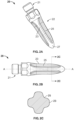
FIG. 2A is a perspective view of a stem according to an embodiment of the present disclosure. -
FIG. 2B is a side view of the stem ofFIG. 2A . -
FIG. 2C is a cross-sectional view of the stem taken along line C-C ofFIG. 2B . -
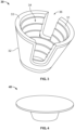
FIG. 3 is a perspective view of a void filling prosthesis according to an embodiment of the present disclosure. -
FIG. 4 is a perspective view of a cement plug according to an embodiment of the present disclosure. -
FIG. 5 is perspective view of a cement restrictor tool according to an embodiment of the present disclosure. -
FIG. 6A is a perspective view of cement pressurizer according to an embodiment of the present disclosure. -
FIG. 6B is a side view of the cement pressurizer ofFIG. 6A . -
FIG. 6C is a bottom view of the cement pressurizer ofFIG. 6A . -
FIGS. 7A and 7B are schematics illustrating a method according to an embodiment of the present disclosure. -
FIG. 8A is a front view of a tibial baseplate according to another embodiment of the present disclosure. -
FIG. 8B is a perspective view of a stem of the tibial baseplate ofFIG. 8A according to another embodiment of the present disclosure. -
FIGS. 9A and 9B are schematics illustrating a method according to another embodiment of the present disclosure. -
FIG. 10A is a top view of a cement restrictor tool according to another embodiment of the present disclosure. -
FIG. 10B is a front view of the cement restrictor tool ofFIG. 10A . -
FIG. 11A is perspective view of a cement pressurizer according to another embodiment of the present disclosure. -
FIG. 11B is a bottom view of the cement pressurizer ofFIG. 11A . -
FIG. 12A is a side view of a femoral prosthesis assembly according to an embodiment of the present disclosure. -
FIG. 12B is a perspective view of a void filling prosthesis of the assembly ofFIG. 12A according to another embodiment of the present disclosure. -
FIG. 13 is a schematic illustrating a method according to a further embodiment of the present disclosure. - When referring to specific directions in the following discussion of certain implantable devices, it should be understood that such directions are described with regard to the implantable device's orientation and position during exemplary application to the human body. Thus, as used herein, the term "proximal" means close to the heart and the term "distal" means more distant from the heart. The term "anterior" means toward the front of the body or the face, and the term "posterior" means toward the back of the body. The term "medial" means toward the midline of the body, and the term "lateral" means away from the midline of the body. Also, as used herein, the terms "about," "generally" and "substantially" are intended to mean that slight deviations from absolute are included within the scope of the term so modified.
-
FIGs. 1A and 1B depict amodular tibial baseplate 10 according to an embodiment of the present disclosure.Tibial baseplate 10 generally includes aplate portion 12, stemboss 14, and keels 16.Plate portion 12 includes an articular side and a bone contact side. The articular side defines atray 13 that is configured to receive a tibial insert (not shown) which has lateral and medial condylar surfaces for articulation with a femoral component. The bone contact side includes a layer ofporous material 18 configured to promote bony ingrowth. An exemplary porous material is disclosed inU.S. Patent No. 10,716,673 porous material 18 defines a generally planarbone contact surface 11.Stem boss 14 extends from the bone contact side ofplate portion 12 and has aconnection opening 15 configured to connect to a stem. In this regard, opening 15 may be tapered for a taper-lock connection or internally threaded for a threaded connection, for example.Keels 16 extend from the bone contact side ofplate portion 12 and from lateral and medial sides ofstem boss 14.Keels 16 help provide rotational resistance when implanted in a tibia. -
FIGs. 2A-2C depict amodular stem 20 according to an embodiment of the present disclosure.Stem 20 generally includes aconnection portion 21 andstem portion 22.Connection portion 21 is configured to connect to stemboss 14 ofbaseplate 12. In this regard,connection portion 21 may be tapered for a taper-lock connection or threaded for a threaded connection.Stem portion 22 extends fromconnection portion 21 and includes a plurality offlutes 23 andgrooves 25 that extend along a length ofstem portion 22 to arounded tip thereof 27. In the embodiment depicted,stem portion 22 includes fourflutes 23 and fourgrooves 25 so thatstem portion 22 forms a cruciform cross-sectional shape, as best shown inFIG. 2C . However, more orless flutes 23 may be provided to form alternative cross-sectional shapes, such as a star shape, for example.Flutes 23 are tapered in the proximodistal, mediolateral, and anteroposterior directions. In other words, eachflute 23 is tapered in the proximodistal direction and a direction transverse to the proximodistal direction.Grooves 25 have a uniform depth along their length for uniform loading and enhanced cement-stem interaction. The cruciform cross-section allows bone cement to become interposed withingrooves 25 whileflutes 23 resist rotation relative to the bone cement. Additionally, the multidirectional taper offlutes 23 facilitates subsidence ofstem 20 within bone cement, as discussed in more detail below. -
FIG. 3 depicts a tibialvoid filling prosthesis 30 according to an embodiment of the present disclosure. Void fillingprosthesis 30 has a frustoconical shape such that its periphery extends about a longitudinal axis and tapers along the longitudinal axis from a first end to a second end thereof. Achannel 34 extends entirely throughprosthesis 30 and is defined by aninterior surface 31.Interior surface 31 may be roughened or corrugated, as shown, to help prevent migration of bone cement disposed withinchannel 34. A layer ofporous material 32 forms an exterior surface ofprosthesis 30 to promote bony ingrowth.Notches 36 extend through asidewall 33 ofprosthesis 30 from the first end thereof which forms a clearance space configured to receivekeels 16. However, in some embodiments,prosthesis 30 may not havesuch notches 36. Void fillingprosthesis 30 can have other shapes and configurations such as those disclosed inU.S. Patent Nos. 9,011,444 9,149,282 10,524,806 10,299,929 -
FIG. 4 depicts a cement plug orrestrictor 40.Plug 40 is made of a generally pliable biocompatible material and is configured to secure itself within an intramedullary canal of a bone to restrict migration of bone cement. -
FIG. 5 depicts acement shield 50 according to an embodiment of the present disclosure.Cement shield 50 generally includes afirst member 51a and asecond member 51b which each include a plate or shieldbody 52 and ahandle 56 extending fromshield body 52. First andsecond members 51a-b are pivotably connected via apin 55 at a location betweenhandles 56 andshield bodies 52. This allowsshield bodies 52 to be moved closer to or further away from each other by actuation ofhandles 56. Eachshield body 52 is shaped to match a portion of a resected end of a bone. In particular, eachshield body 52 is shaped to match a portion of a resected proximal tibia which ordinarily has a planar resected surface. In this regard, eachshield body 52 has aplanar shield surface 53 for engagement with the resected surface and, whenshield bodies 52 are brought together, they collectively form a shape that can cover the proximal resected surface of a tibia. In an embodiment configured for a resected femur (not shown), each shield body may have two to five planar intersecting surfaces that each correspond to a resected surface of a distal femur for conformal engagement therewith. - Each
shield body 52 defines anotch 54 that faces thenotch 54 of theother shield body 52 so that when theshield bodies 52 are brought together,notches 54 form achannel 58, which is shown to be circular to correspond to a periphery ofstem 20 but with a larger diameter than a maximum major diameter ofstem 20. Each handle has aratchet arm 57 extending therefrom that engages theratchet arm 57 of theother handle 56 to form a ratchet mechanism. The ratchet mechanism helps secure first andsecond members 51a-b in one of a plurality of positions. For example, first andsecond members 57 may have a first or closed position in whichshield bodies 52 either touch or are nearly touching, and a second or open position in whichshield bodies 52 are separated from each other by a distance greater than in the first position. In the closed position, stem 20 can be inserted throughchannel 58. In the open position,channel 58 is opened so thatshield bodies 51a-b are able to be maneuvered away fromstem 20. -
FIGs. 6A-6B depict acement pressurizer 60 according to an embodiment of the present disclosure.Pressurizer 60 generally includes aconnection portion 62,shaft 64,flange 66, andprojection 68.Connection portion 62 is configured to connect, via a quick-connect mechanism or otherwise, to another instrument, such as an impaction handle for impaction by a mallet or the like.Shaft 64 extends fromconnection portion 62. Flange or plate is disposed at an end ofshaft 64 opposite that ofconnection portion 62 and has a planardistal surface 61. Flange extends 66 radially outwardly and has a peripheral shape dimensioned to be at least as equal to a maximum outer dimension ofvoid filling prosthesis 30 and preferably greater so that it seats against a resected surface of a tibia in use. For example, in the embodiment depicted,flange 66 is disc shaped, and void fillingprosthesis 30 is frustoconical such that its maximum diameter is located at one end thereof.Flange 66 may have a diameter at least equal to the maximum diameter ofprosthesis 30. However,flange 66 preferably has a diameter larger than that ofprosthesis 30 so that it extends beyond the boundaries ofvoid filling prosthesis 30 and substantially covers the resected surface or surfaces of a tibia. -
Projection 68 on the other hand is dimensioned to substantially conform to an interior ofvoid filling prosthesis 30. Thus, for the embodiment depicted,projection 68 matches the size and conical taper ofinterior cone surface 31 ofvoid filling prosthesis 30. In this regard,projection 68 pressurizes the bone cement while flange 66 acts as a depth stop.Projection 68 extends distally fromflange 66 and has adepression 63 extending proximally therein, as best shown inFIG. 6C .Projection 68 creates a relief space for bone cement to travel to while the bone cement withinvoid filling prosthesis 30 is pressurized viaprojection 68. The snug fit ofprojection 68 anddepression 63 helps ensure that bone cement does not escape from betweenprojection 68 andinterior cone surface 31. Sincevoid filling prosthesis 30 may come in several different sizes, a kit may include several differentlysized pressurizers 60 corresponding to each sizevoid filling prosthesis 30. - A method of using the foregoing instruments and implants to perform a revision TKA will now be described. In the revision procedure, a previously implanted prosthesis is removed from a
tibia 70, and the proximal end of the tibia is resected to resurface the bone for the revision prosthesis. In other words, the proximal tibia is resected to form a proximal resectedsurface 72, as shown inFIG. 7A . Additionally,tibia 70 may be prepared forvoid filling prosthesis 30. Exemplary preparation techniques are described in the heretofore incorporated disclosures ofU.S. Patent Nos. 9,011,444 9,149,282 10,524,806 10,299,929 tibia 70 so that it is properly shaped to accommodatevoid filling prosthesis 30. - Once the proximal end of
tibia 70 has been prepared,cement plug 40 is inserted into the intramedullary canal oftibia 70 so that it is positioned within the diaphysis ofbone 70 distal of the metaphysis. Thereafter,void filling prosthesis 30 is implanted intotibia 70 preferably in a press-fit manner so that itsporous exterior surface 32 bears against the bleeding cancellous bone of the metaphysis.Bone cement 80 is then injected or otherwise inserted intotibia 70 so that the space betweencement plug 40 and resectedsurface 72, includingchannel 34 ofvoid filling prosthesis 30, is substantially filled withbone cement 80.Bone cement 80 is then pressurized by insertingprojection 68 ofpressurizer 60 intochannel 34 ofvoid filling prosthesis 30 and either pushing down on thebone cement 80 by hand or using a mallet to impact an impaction tool connected to pressurizer 60 to tampbone cement 80 to the desired pressure, as shown inFIG. 7A . At this point, resectedsurface 72 should be substantially free ofbone cement 80. -
Cement shield 50 is then placed onto resectedsurface 72. In this regard, shieldbodies 52 are moved to the closed position and placed into contact with resectedsurface 72 so thatchannel 58 is centered overcement 80. While maintainingshield 50 against resectedsurface 72, stem 20 is inserted intocement 80 which causescement 80 to flow or otherwise eject fromtibia 70.Shield 50 prevents the overflow ofcement 80 from coming into contact with resectedsurface 72 and instead directs the overflow up throughchannel 58 ofshield 50 and around stem 20. The overflow cement is removed as it is expelled frombone 70. Just asbaseplate 10 comes into contact or nearly comes into contact withshield bodies 52,shield 50 is removed frombone 70 by actuatinghandles 56 and movingshield bodies 52 to the open position.Tibial baseplate 10 is then seated onto theproximal tibia 70 so that porousdistal surface 18 directly contacts resectedsurface 72 which should be substantially free ofcement 80.Bone cement 80 is then allowed to cure. Thus, the interface betweenplate portion 12 andproximal tibia 72 is cementless, while the interface betweenstem 20 andbone 70/void filler 30 is cemented. Over time and with use, stem 20 may subside further withinbone cement 80 which helps facilitate load transfer to the interface betweenplate portion 12 and resectedsurface 72. However, stem 20 remains cemented and helps resist rotational forces at least due to its cruciform shape. - It should be noted that
stem 20 extends throughchannel 34 ofvoid filling prosthesis 30 so thatdistal tip 27 ofstem 20 is positioned within the diaphysis oftibia 70. In this regard, stem 20 has a length that facilitates the positioning ofdistal tip 27 within the diaphysis. However, stem 20 may have shortened length such thatdistal tip 27 terminates within the metaphysis oftibia 70. Since the metaphysis is generally less constraining than the diaphysis, such shortenedstem 20 may allow the positioning oftibial baseplate 10 at different varus-valgus angles than just a neutral position. Additionally, the need for a stem offset may be precluded as the shortenedstem 20 may allowbaseplate 10 to be shifted medially-laterally and/or anteriorly-posteriorly to find the proper positioning ofplate portion 12 onbone 70 prior tocement 80 curing. Additionally, some embodiments of the method may not utilizevoid filling prosthesis 30. -
FIGs. 8A-8B depict atibial baseplate 110 according to another embodiment of the present disclosure. For ease of review, like elements will be accorded like reference numerals to that ofbaseplate 10 and stem 20 but within the 100-series of numbers.Tibial baseplate 110 is a monolithic baseplate in thatstem 120 is integral withplate portion 112.Plate portion 112 is similar toplate portion 12 in that it includes an articular side that defines atray 113 for a tibial insert and an articular side that includes a layer ofporous material 118 which defines abone contact surface 111 configured for bony ingrowth. - Integral stem 120 is similar to stem 20 in that it includes a plurality of
flutes 123 andgrooves 125 that form a cruciform cross-section. However,flutes 123 ofstem 120 have a dual axial taper. In this regard, flutes 123 each have a flute height H that extends from aroot 127 to atip 129 thereof. This flute height H decreases at two different rates, so that the distance betweenroot 127 and tip 129 of eachflute 123 decreases along a first length portion L1 ofstem 120 at a first taper angle and a second length portion L2 ofstem 120 at a second taper angle. The first taper angle may have the same taper angle as that of an interior ofvoid filling prosthesis 30. The second taper angle may be a greater taper angle than that of the first taper angle. In other words, second length portion L2 may taper at a greater rate than L1 to facilitate subsidence. The transition between L1 and L2 may be dependent on a length ofvoid filling prosthesis 30, for example. In this regard, L1 may be the same length asvoid filling prosthesis 30. In such embodiment, the transition between L1 and L2 may then be located a distance from a distal tip ofstem 120 that is equal to the difference between the total length ofstem 120 and L1 (or length of prosthesis 30). Such dual taper facilitates subsidence ofstem 120 in bone cement and helps convert tension at the cement interface into compression. Moreover, subsidence, as mentioned above, allows for the reduction in any distance between a bone andbone contact surface 111 ofbaseplate 110 and facilitates complete and even loading perpendicular to this interface. - The first taper of
stem 120 along first length portion L1 may match the taper ofchannel 30 withinvoid filling prosthesis 30. Additionally, an outer periphery or dimension ofstem 120 along length L1 may closely correspond to an inner dimension ofvoid filling prosthesis 30 alongchannel 34. For example, stemflutes 123 and aninner surface 31 ofvoid filling prosthesis 30 may have a maximum offset of about 1 cm. This allowsstem 120 to dock to void fillingprosthesis 30 while allowing stem 120 the ability to subside within bone cement betweengrooves 125 andvoid filling prosthesis 30. In this regard,void filling prosthesis 30 can help direct the orientation ofbaseplate portion 112 or whatever joint prosthesis is connected to stem 120. -
FIGs. 9A and 9B illustrate a benefit of the docking effect as it can facilitate the use of a kinematic alignment revision procedure. As shown in the cross-section ofFIG. 9B , stemflutes 123 andvoid filling prosthesis 30 in one cross-sectional plane have a total offset which is great enough to allow subsidence to proceed unimpeded but is constraining enough to restrict the angulation of a longitudinal axis SA ofstem 120 relative to a longitudinal axis VPA ofvoid filling prosthesis 30. In other words, stem 120 andvoid filling prosthesis 30 are self-aligning whenstem 120 is docked to void fillingprosthesis 30. This allowsbaseplate 110 andvoid filing prosthesis 30 to be used in a kinematic alignment revision procedure. As shown inFIG. 9A , a typical anatomic alignment procedure would resecttibia 170 parallel to a neutraljoint line 174 so that resectedsurface 172 oftibia 170 is oriented perpendicular to a tibial mechanical axis MA. However, the patient's natural j oint line may be naturally varus or valgus. In this regard, a kinematic procedure may be performed so that the joint line, and correspondingly resectedsurface 172, is oriented at an angle Θ relative to the neutraljoint line 174 and parallel to the patient's natural kinematic joint line. Longitudinal axes SA and VPA ofvoid filling prosthesis 30 andstem 120, respectively, are similarly rotated relative to the tibial mechanical axis MA by angle Θ. In the procedure, a robot or surgeon with the aid of a computer-assisted haptic feedback system can be used to shapebone 170 forvoid filling prosthesis 30 andtibial component 110. Exemplary manual and computer-assisted kinematic alignment techniques that may be used to resect the bones of the knee joint are respectively disclosed inU.S. Patent No. 8,974,459 andU.S. Pub. No. 2021/0346036 , the disclosures of which are hereby incorporated by reference herein in their entireties. In this regard, a conical burr or reamer may be used form resectedsurface 172 to shape the metaphyseal bone cavity to receivevoid filling prosthesis 30 at the desired orientation. Oncevoid filling prosthesis 30 has been implanted andcement 180 inserted into the cavity betweenplug 40 and resectedsurface 172, stem 120 ofbaseplate 110 is then inserted intovoid filling prosthesis 30. The conformal nature ofstem 120 andvoid filling prosthesis 30 self-orients stem 120 and, consequently,tibial baseplate 110 to the proper kinematic orientation. It is noted thatshield 50 may also be used to prevent cement contamination of resectedsurface 172 so that direct contact can be made betweenporous material 118 ofbaseplate 110 and resectedsurface 172. -
FIGs. 10A-10B depict acement shield 150 according to another embodiment of the present disclosure. For ease of review, like elements will be accorded like reference numerals to that ofcement shield 50 but within the 100-series of numbers.Shield 150 is similar to shield 50 in that it includesshield bodies 152 shaped to overlap a resected proximal tibia. In addition, achannel 158 is formed betweenshield bodies 152. However, unlikeshield 50,bodies 152 are rigidly fixed relative to each other via abridge 155 extending between them. Thus,channel 158 runs out a posterior side ofshield 150 to facilitate its removal from a stem sincechannel 158 cannot be opened via actuation of a handle. In this regard,shield 150 does not have moveable handles. Instead, bridge 155 may have atool interface 157 configured to receive a separate handle for manipulation of shield. Alternatively, an integral handle may be connected to shield 150 at thistool interface 157. -
FIGs. 11A-11B depict acement pressurizer 160 according to another embodiment of the present disclosure. For ease of review, like elements will be accorded like reference numerals to that ofcement pressurizer 60 but within the 100-series of numbers.Cement pressurizer 160 is similar topressurizer 60 in that it includes ashaft 164 with a flange orplate 166 disposed at the end ofshaft 164 and aprojection 168 extending fromflange 166. Moreover,projection 168 is shaped and sized to be received withinchannel 34 ofvoid filling prosthesis 30. However, pressurizer 160 is not configured to connect to another tool, andshaft 164 forms a handle for manual manipulation. -
FIGs. 12A and 12B depicts afemoral assembly 200 according to an embodiment of the present disclosure.Femoral assembly 200 generally includes afemoral component 210, astem 220 extending fromfemoral component 210, and avoid filling prosthesis 230.Femoral component 210 includes an articular side and a bone contact side. The articular side has a pair ofcondyles 212 for articulation with corresponding condyles of a tibial insert. The bone contact side includes a plurality of intersecting planar surfaces, such as three to five planar surfaces, for example. One or more of such planar surfaces includes a layer ofporous material 211 for bony ingrowth.Stem 220 extends fromfemoral component 210 and may be similar to either stem 30 or 130. However, in the embodiment depicted it is similar to stem 130 in that it has a periphery configured for docking withvoid filling prosthesis 230. - Void filling
prosthesis 230, as shown inFIG. 12 , has a frustoconical shape and includes acentral body 233 and a pair of opposinglegs 231a-b that define aspace 235 therebetween. Achannel 234 extends axially throughcentral body 235 in a proximodistal direction and also throughbody 233 in an anterior direction which helps provide clearance space betweenvoid filling prosthesis 230 andfemoral component 211. An exterior surface ofvoid filling prosthesis 230 includes a layer of aporous material 232 for bony ingrowth. Other configurations for femoral void filling prosthesis are contemplated, such as those disclosed in the heretofore incorporated disclosures ofU.S. Patent Nos. 9,011,444 9,149,282 10,524,806 -
FIG. 13 depicts afemoral assembly 200 implanted onto adistal femur 270. The method for implantation is the same as that described above with respect to the tibial devices except that the procedure is performed on afemur 270 using analog femoral devices. In this regard,femur 270 is prepared,bone plug 40 is inserted intofemur 270 followed byvoid filling prosthesis 230,cement 280 is inserted,cement 280 is pressurized, a cement shield configured forfemur 270 is applied one or more resected surfaces ofbone 270 surrounding the cement filled void, and stem 220 is inserted intobone cement 280 while shielding the resected surfaces offemur 270 frombone cement 280. - A total knee arthroplasty system may include
tibial baseplate void filling prosthesis cement plug 40,cement shield cement pressurizer femoral assembly 200. A kit may include multiple sizes of each of such system devices. - Although the invention herein has been described with reference to particular embodiments, it is to be understood that these embodiments are merely illustrative of the principles and applications of the present invention. It is therefore to be understood that numerous modifications may be made to the illustrative embodiments and that other arrangements may be devised without departing from the spirit and scope of the present invention as defined by the appended claims.
Claims (15)
- A total knee arthroplasty system, comprising:a joint prosthesis having a joint component and a stem extending from the joint component, the joint component having an articular side and a bone contact side, the articular side having first and second condyles, and the bone contact side having a porous bone contact surface;a void filling prosthesis having a porous outer surface and a channel extending entirely through the void filling prosthesis and configured to receive the stem of the joint prosthesis;a cement plug; anda cement shield having a first member and a second member, the first member and the second member defining a channel extending through the cement shield and having a planar surface configured to abut a resected surface of a bone so that the channel aligns with an intramedullary canal of the bone.
- The system of claim 1, wherein the first and second members of the shield are moveable relative to each other from an open position to a closed position.
- The system of claim 2, wherein each of the first and second members each include a shield body having a notch such that when the first and second members are in the closed position, the notches of the first and second members come together to form the channel.
- The system of claim 3, wherein the first and second members are pivotably connected to each other.
- The system of claim 4, wherein the first and second members include a ratchet mechanism that secures the first and second members while in the open and closed positions.
- The system of claim 1, further comprising a cement pressurizer having an elongate shaft and a flange extending radially outwardly from an end of the elongate shaft.
- The system of claim 6, wherein the flange has a periphery corresponding to a periphery of the channel of the void filling prosthesis.
- The system of claim 6, wherein the cement pressurizer includes a projection extending from the flange in an axial direction and having a depression therein.
- The system of claim 6, wherein the projection is cylindrical.
- The system of claim 1, wherein the joint prosthesis is a tibial prosthesis, and the joint component is a tibial baseplate.
- The system of claim 10, wherein the void filling prosthesis includes notches extending through a sidewall thereof and configured to receive keels of the tibial baseplate.
- The system of claim 10, wherein the stem includes a connection portion and a stem portion, the stem portion includes a plurality of flutes and grooves forming a cruciform cross-sectional shape.
- The system of claim 12, wherein each flute is tapered in a proximodistal direction and a direction transverse to the proximodistal direction.
- The system of claim 1, wherein the joint prosthesis is a femoral prosthesis, and the joint component is a distal femoral component.
- The system of claim 14, wherein void filling prosthesis has a frustoconical shape and includes a central body and a pair of opposing legs that define a space therebetween.
Applications Claiming Priority (1)
| Application Number | Priority Date | Filing Date | Title |
|---|---|---|---|
| US202263317123P | 2022-03-07 | 2022-03-07 |
Publications (2)
| Publication Number | Publication Date |
|---|---|
| EP4241739A1 true EP4241739A1 (en) | 2023-09-13 |
| EP4241739B1 EP4241739B1 (en) | 2024-07-10 |
Family
ID=85511023
Family Applications (1)
| Application Number | Title | Priority Date | Filing Date |
|---|---|---|---|
| EP23160570.0A Active EP4241739B1 (en) | 2022-03-07 | 2023-03-07 | Hybrid knee prosthesis |
Country Status (3)
| Country | Link |
|---|---|
| US (1) | US20230277325A1 (en) |
| EP (1) | EP4241739B1 (en) |
| AU (1) | AU2023201401A1 (en) |
Citations (11)
| Publication number | Priority date | Publication date | Assignee | Title |
|---|---|---|---|---|
| US8974459B1 (en) | 2010-05-21 | 2015-03-10 | Howmedica Osteonics Corp. | Natural alignment knee instruments |
| US9011444B2 (en) | 2011-12-09 | 2015-04-21 | Howmedica Osteonics Corp. | Surgical reaming instrument for shaping a bone cavity |
| US20150164645A1 (en) * | 2013-03-14 | 2015-06-18 | Depuy (Ireland) | Orthopaedic tibial prosthesis having tibial augments |
| US9149282B2 (en) | 2011-12-30 | 2015-10-06 | Howmedica Osteonics Corp. | Systems and methods for preparing bone voids to receive a prosthesis |
| US20190070008A1 (en) * | 2015-07-09 | 2019-03-07 | Waldemar Link Gmbh & Co. Kg | Hollow sleeve augment device and tool |
| US10299929B2 (en) | 2015-01-12 | 2019-05-28 | Howmedica Osteonics Corp. | Bone void forming apparatus |
| US20190358044A1 (en) * | 2018-05-25 | 2019-11-28 | Howmedica Osteonics Corp. | Variable Thickness Femoral Augments |
| US10524806B2 (en) | 2013-03-13 | 2020-01-07 | Howmedica Osteonics Corp. | Void filling joint prosthesis and associated instruments |
| US10716673B2 (en) | 2005-12-06 | 2020-07-21 | Howmedica Osteonics Corp. | Laser-produced porous surface |
| US20210228366A1 (en) * | 2020-01-29 | 2021-07-29 | Encore Medical, LP (d/b/a DJO Surgical) | Modular knee augment cones |
| US20210346036A1 (en) | 2018-09-19 | 2021-11-11 | Mako Surgical Corp. | Method of Surgery |
Family Cites Families (6)
| Publication number | Priority date | Publication date | Assignee | Title |
|---|---|---|---|---|
| US5004476A (en) * | 1989-10-31 | 1991-04-02 | Tulane University | Porous coated total hip replacement system |
| US5755720A (en) * | 1997-01-03 | 1998-05-26 | Mikhail Michael W E | Method and apparatus for performing hip prosthesis surgery |
| US20100298947A1 (en) * | 2009-04-22 | 2010-11-25 | Unger Anthony S | Precision Total Knee Arthroplasty |
| US9820858B2 (en) * | 2015-03-23 | 2017-11-21 | Modal Manufacturing, LLC | Knee implants and instruments |
| US10856992B2 (en) * | 2016-04-27 | 2020-12-08 | AOD Holdings, LLC | Implant device(s) including tapered protrusions and method(s) for inserting the same into bone |
| US20230157831A1 (en) * | 2021-11-19 | 2023-05-25 | Microport Orthopedics Holdings Inc. | Tibial component of endoprosthetic knee implant, kits and instruments therefore, and methods of use |
-
2023
- 2023-03-07 US US18/118,371 patent/US20230277325A1/en active Pending
- 2023-03-07 AU AU2023201401A patent/AU2023201401A1/en active Pending
- 2023-03-07 EP EP23160570.0A patent/EP4241739B1/en active Active
Patent Citations (11)
| Publication number | Priority date | Publication date | Assignee | Title |
|---|---|---|---|---|
| US10716673B2 (en) | 2005-12-06 | 2020-07-21 | Howmedica Osteonics Corp. | Laser-produced porous surface |
| US8974459B1 (en) | 2010-05-21 | 2015-03-10 | Howmedica Osteonics Corp. | Natural alignment knee instruments |
| US9011444B2 (en) | 2011-12-09 | 2015-04-21 | Howmedica Osteonics Corp. | Surgical reaming instrument for shaping a bone cavity |
| US9149282B2 (en) | 2011-12-30 | 2015-10-06 | Howmedica Osteonics Corp. | Systems and methods for preparing bone voids to receive a prosthesis |
| US10524806B2 (en) | 2013-03-13 | 2020-01-07 | Howmedica Osteonics Corp. | Void filling joint prosthesis and associated instruments |
| US20150164645A1 (en) * | 2013-03-14 | 2015-06-18 | Depuy (Ireland) | Orthopaedic tibial prosthesis having tibial augments |
| US10299929B2 (en) | 2015-01-12 | 2019-05-28 | Howmedica Osteonics Corp. | Bone void forming apparatus |
| US20190070008A1 (en) * | 2015-07-09 | 2019-03-07 | Waldemar Link Gmbh & Co. Kg | Hollow sleeve augment device and tool |
| US20190358044A1 (en) * | 2018-05-25 | 2019-11-28 | Howmedica Osteonics Corp. | Variable Thickness Femoral Augments |
| US20210346036A1 (en) | 2018-09-19 | 2021-11-11 | Mako Surgical Corp. | Method of Surgery |
| US20210228366A1 (en) * | 2020-01-29 | 2021-07-29 | Encore Medical, LP (d/b/a DJO Surgical) | Modular knee augment cones |
Also Published As
| Publication number | Publication date |
|---|---|
| EP4241739B1 (en) | 2024-07-10 |
| US20230277325A1 (en) | 2023-09-07 |
| AU2023201401A1 (en) | 2023-09-21 |
Similar Documents
| Publication | Publication Date | Title |
|---|---|---|
| CN102014800B (en) | Partial joint resurfacing implant, instrumentation, and method | |
| US7338498B2 (en) | Prosthetic implant, trial and associated method | |
| US9216085B2 (en) | Partial joint resurfacing implant, instrumentation, and method | |
| AU2018204282B2 (en) | Surgical instrument with multiple lengths of broaches sharing a common geometry | |
| RU2744481C2 (en) | System and method for preparing a femoral bone of a patient when performing an orthopedic operation of arthroplasty | |
| EP3146919B1 (en) | Orthopaedic surgical instrument system | |
| EP2679201B1 (en) | Instrument for assembling and disassembling prosthesis components | |
| US20060030855A1 (en) | Methods and apparatus for improved profile based resection | |
| JP2019506281A (en) | Shoulder arthroplasty implant system | |
| JPH01250250A (en) | Apparatus used in knee prosthesis method | |
| JP2019516488A (en) | System and method for preparing a patient's tibia in orthopedic joint replacement | |
| AU2019203591B2 (en) | Variable thickness femoral augments | |
| EP2712589B1 (en) | Surgical instrument | |
| JP6362884B2 (en) | Surgical instruments and methods of use | |
| JP4694117B2 (en) | Cemented prosthesis kit | |
| CN109498223B (en) | Orthopedic instrument system and method for separating a trial build assembly | |
| EP4241739B1 (en) | Hybrid knee prosthesis | |
| EP3984502A2 (en) | Self-broaching neck preserving hip stem | |
| US20240207067A1 (en) | Orthopaedic surgical instrument, system, and method for installing a cemented femoral stem component in a direct anterior approach hip replacement surgical procedure | |
| Vince et al. | Revision Knee Arthroplasty: Surgical Guidelines | |
| Springer | Adjunctive Fixation in Total Knee Arthroplasty Revision: Stems and Sleeves | |
| Marega | Technique of Modular | |
| Rollier et al. | the Advice of Your Elders |
Legal Events
| Date | Code | Title | Description |
|---|---|---|---|
| PUAI | Public reference made under article 153(3) epc to a published international application that has entered the european phase |
Free format text: ORIGINAL CODE: 0009012 |
|
| STAA | Information on the status of an ep patent application or granted ep patent |
Free format text: STATUS: REQUEST FOR EXAMINATION WAS MADE |
|
| 17P | Request for examination filed |
Effective date: 20230307 |
|
| AK | Designated contracting states |
Kind code of ref document: A1 Designated state(s): AL AT BE BG CH CY CZ DE DK EE ES FI FR GB GR HR HU IE IS IT LI LT LU LV MC ME MK MT NL NO PL PT RO RS SE SI SK SM TR |
|
| GRAP | Despatch of communication of intention to grant a patent |
Free format text: ORIGINAL CODE: EPIDOSNIGR1 |
|
| STAA | Information on the status of an ep patent application or granted ep patent |
Free format text: STATUS: GRANT OF PATENT IS INTENDED |
|
| RIC1 | Information provided on ipc code assigned before grant |
Ipc: A61F 2/46 20060101ALI20240403BHEP Ipc: A61F 2/38 20060101ALI20240403BHEP Ipc: A61F 2/30 20060101AFI20240403BHEP |
|
| INTG | Intention to grant announced |
Effective date: 20240426 |
|
| RIN1 | Information on inventor provided before grant (corrected) |
Inventor name: DUNBAR, MICHAEL JAMES Inventor name: PASCALE, KENNETH Inventor name: PATTNAIK, PRAMIT Inventor name: KAYAL, JORDAN |
|
| GRAS | Grant fee paid |
Free format text: ORIGINAL CODE: EPIDOSNIGR3 |
|
| GRAA | (expected) grant |
Free format text: ORIGINAL CODE: 0009210 |
|
| STAA | Information on the status of an ep patent application or granted ep patent |
Free format text: STATUS: THE PATENT HAS BEEN GRANTED |
|
| P01 | Opt-out of the competence of the unified patent court (upc) registered |
Effective date: 20240523 |
|
| AK | Designated contracting states |
Kind code of ref document: B1 Designated state(s): AL AT BE BG CH CY CZ DE DK EE ES FI FR GB GR HR HU IE IS IT LI LT LU LV MC ME MK MT NL NO PL PT RO RS SE SI SK SM TR |
|
| REG | Reference to a national code |
Ref country code: CH Ref legal event code: EP |
|
| REG | Reference to a national code |
Ref country code: DE Ref legal event code: R096 Ref document number: 602023000213 Country of ref document: DE |
|
| REG | Reference to a national code |
Ref country code: LT Ref legal event code: MG9D |
|
| REG | Reference to a national code |
Ref country code: NL Ref legal event code: MP Effective date: 20240710 |
|
| PG25 | Lapsed in a contracting state [announced via postgrant information from national office to epo] |
Ref country code: PT Free format text: LAPSE BECAUSE OF FAILURE TO SUBMIT A TRANSLATION OF THE DESCRIPTION OR TO PAY THE FEE WITHIN THE PRESCRIBED TIME-LIMIT Effective date: 20241111 |
|
| REG | Reference to a national code |
Ref country code: AT Ref legal event code: MK05 Ref document number: 1701382 Country of ref document: AT Kind code of ref document: T Effective date: 20240710 |
|
| PG25 | Lapsed in a contracting state [announced via postgrant information from national office to epo] |
Ref country code: NL Free format text: LAPSE BECAUSE OF FAILURE TO SUBMIT A TRANSLATION OF THE DESCRIPTION OR TO PAY THE FEE WITHIN THE PRESCRIBED TIME-LIMIT Effective date: 20240710 |
|
| PG25 | Lapsed in a contracting state [announced via postgrant information from national office to epo] |
Ref country code: PT Free format text: LAPSE BECAUSE OF FAILURE TO SUBMIT A TRANSLATION OF THE DESCRIPTION OR TO PAY THE FEE WITHIN THE PRESCRIBED TIME-LIMIT Effective date: 20241111 Ref country code: NL Free format text: LAPSE BECAUSE OF FAILURE TO SUBMIT A TRANSLATION OF THE DESCRIPTION OR TO PAY THE FEE WITHIN THE PRESCRIBED TIME-LIMIT Effective date: 20240710 |
|
| PG25 | Lapsed in a contracting state [announced via postgrant information from national office to epo] |
Ref country code: NO Free format text: LAPSE BECAUSE OF FAILURE TO SUBMIT A TRANSLATION OF THE DESCRIPTION OR TO PAY THE FEE WITHIN THE PRESCRIBED TIME-LIMIT Effective date: 20241010 |
|
| PG25 | Lapsed in a contracting state [announced via postgrant information from national office to epo] |
Ref country code: GR Free format text: LAPSE BECAUSE OF FAILURE TO SUBMIT A TRANSLATION OF THE DESCRIPTION OR TO PAY THE FEE WITHIN THE PRESCRIBED TIME-LIMIT Effective date: 20241011 Ref country code: FI Free format text: LAPSE BECAUSE OF FAILURE TO SUBMIT A TRANSLATION OF THE DESCRIPTION OR TO PAY THE FEE WITHIN THE PRESCRIBED TIME-LIMIT Effective date: 20240710 Ref country code: PL Free format text: LAPSE BECAUSE OF FAILURE TO SUBMIT A TRANSLATION OF THE DESCRIPTION OR TO PAY THE FEE WITHIN THE PRESCRIBED TIME-LIMIT Effective date: 20240710 |
|
| PG25 | Lapsed in a contracting state [announced via postgrant information from national office to epo] |
Ref country code: BG Free format text: LAPSE BECAUSE OF FAILURE TO SUBMIT A TRANSLATION OF THE DESCRIPTION OR TO PAY THE FEE WITHIN THE PRESCRIBED TIME-LIMIT Effective date: 20240710 |
|
| PG25 | Lapsed in a contracting state [announced via postgrant information from national office to epo] |
Ref country code: LV Free format text: LAPSE BECAUSE OF FAILURE TO SUBMIT A TRANSLATION OF THE DESCRIPTION OR TO PAY THE FEE WITHIN THE PRESCRIBED TIME-LIMIT Effective date: 20240710 |
|
| PG25 | Lapsed in a contracting state [announced via postgrant information from national office to epo] |
Ref country code: IS Free format text: LAPSE BECAUSE OF FAILURE TO SUBMIT A TRANSLATION OF THE DESCRIPTION OR TO PAY THE FEE WITHIN THE PRESCRIBED TIME-LIMIT Effective date: 20241110 Ref country code: AT Free format text: LAPSE BECAUSE OF FAILURE TO SUBMIT A TRANSLATION OF THE DESCRIPTION OR TO PAY THE FEE WITHIN THE PRESCRIBED TIME-LIMIT Effective date: 20240710 |
|
| PG25 | Lapsed in a contracting state [announced via postgrant information from national office to epo] |
Ref country code: HR Free format text: LAPSE BECAUSE OF FAILURE TO SUBMIT A TRANSLATION OF THE DESCRIPTION OR TO PAY THE FEE WITHIN THE PRESCRIBED TIME-LIMIT Effective date: 20240710 |
|
| PG25 | Lapsed in a contracting state [announced via postgrant information from national office to epo] |
Ref country code: ES Free format text: LAPSE BECAUSE OF FAILURE TO SUBMIT A TRANSLATION OF THE DESCRIPTION OR TO PAY THE FEE WITHIN THE PRESCRIBED TIME-LIMIT Effective date: 20240710 Ref country code: RS Free format text: LAPSE BECAUSE OF FAILURE TO SUBMIT A TRANSLATION OF THE DESCRIPTION OR TO PAY THE FEE WITHIN THE PRESCRIBED TIME-LIMIT Effective date: 20241010 |
|
| PG25 | Lapsed in a contracting state [announced via postgrant information from national office to epo] |
Ref country code: RS Free format text: LAPSE BECAUSE OF FAILURE TO SUBMIT A TRANSLATION OF THE DESCRIPTION OR TO PAY THE FEE WITHIN THE PRESCRIBED TIME-LIMIT Effective date: 20241010 Ref country code: PL Free format text: LAPSE BECAUSE OF FAILURE TO SUBMIT A TRANSLATION OF THE DESCRIPTION OR TO PAY THE FEE WITHIN THE PRESCRIBED TIME-LIMIT Effective date: 20240710 Ref country code: NO Free format text: LAPSE BECAUSE OF FAILURE TO SUBMIT A TRANSLATION OF THE DESCRIPTION OR TO PAY THE FEE WITHIN THE PRESCRIBED TIME-LIMIT Effective date: 20241010 Ref country code: LV Free format text: LAPSE BECAUSE OF FAILURE TO SUBMIT A TRANSLATION OF THE DESCRIPTION OR TO PAY THE FEE WITHIN THE PRESCRIBED TIME-LIMIT Effective date: 20240710 Ref country code: IS Free format text: LAPSE BECAUSE OF FAILURE TO SUBMIT A TRANSLATION OF THE DESCRIPTION OR TO PAY THE FEE WITHIN THE PRESCRIBED TIME-LIMIT Effective date: 20241110 Ref country code: HR Free format text: LAPSE BECAUSE OF FAILURE TO SUBMIT A TRANSLATION OF THE DESCRIPTION OR TO PAY THE FEE WITHIN THE PRESCRIBED TIME-LIMIT Effective date: 20240710 Ref country code: GR Free format text: LAPSE BECAUSE OF FAILURE TO SUBMIT A TRANSLATION OF THE DESCRIPTION OR TO PAY THE FEE WITHIN THE PRESCRIBED TIME-LIMIT Effective date: 20241011 Ref country code: FI Free format text: LAPSE BECAUSE OF FAILURE TO SUBMIT A TRANSLATION OF THE DESCRIPTION OR TO PAY THE FEE WITHIN THE PRESCRIBED TIME-LIMIT Effective date: 20240710 Ref country code: ES Free format text: LAPSE BECAUSE OF FAILURE TO SUBMIT A TRANSLATION OF THE DESCRIPTION OR TO PAY THE FEE WITHIN THE PRESCRIBED TIME-LIMIT Effective date: 20240710 Ref country code: BG Free format text: LAPSE BECAUSE OF FAILURE TO SUBMIT A TRANSLATION OF THE DESCRIPTION OR TO PAY THE FEE WITHIN THE PRESCRIBED TIME-LIMIT Effective date: 20240710 Ref country code: AT Free format text: LAPSE BECAUSE OF FAILURE TO SUBMIT A TRANSLATION OF THE DESCRIPTION OR TO PAY THE FEE WITHIN THE PRESCRIBED TIME-LIMIT Effective date: 20240710 |
|
| REG | Reference to a national code |
Ref country code: DE Ref legal event code: R097 Ref document number: 602023000213 Country of ref document: DE |
|
| PG25 | Lapsed in a contracting state [announced via postgrant information from national office to epo] |
Ref country code: RO Free format text: LAPSE BECAUSE OF FAILURE TO SUBMIT A TRANSLATION OF THE DESCRIPTION OR TO PAY THE FEE WITHIN THE PRESCRIBED TIME-LIMIT Effective date: 20240710 Ref country code: DK Free format text: LAPSE BECAUSE OF FAILURE TO SUBMIT A TRANSLATION OF THE DESCRIPTION OR TO PAY THE FEE WITHIN THE PRESCRIBED TIME-LIMIT Effective date: 20240710 Ref country code: SM Free format text: LAPSE BECAUSE OF FAILURE TO SUBMIT A TRANSLATION OF THE DESCRIPTION OR TO PAY THE FEE WITHIN THE PRESCRIBED TIME-LIMIT Effective date: 20240710 |
|
| PG25 | Lapsed in a contracting state [announced via postgrant information from national office to epo] |
Ref country code: EE Free format text: LAPSE BECAUSE OF FAILURE TO SUBMIT A TRANSLATION OF THE DESCRIPTION OR TO PAY THE FEE WITHIN THE PRESCRIBED TIME-LIMIT Effective date: 20240710 |
|
| PG25 | Lapsed in a contracting state [announced via postgrant information from national office to epo] |
Ref country code: CZ Free format text: LAPSE BECAUSE OF FAILURE TO SUBMIT A TRANSLATION OF THE DESCRIPTION OR TO PAY THE FEE WITHIN THE PRESCRIBED TIME-LIMIT Effective date: 20240710 |
|
| PG25 | Lapsed in a contracting state [announced via postgrant information from national office to epo] |
Ref country code: IT Free format text: LAPSE BECAUSE OF FAILURE TO SUBMIT A TRANSLATION OF THE DESCRIPTION OR TO PAY THE FEE WITHIN THE PRESCRIBED TIME-LIMIT Effective date: 20240710 Ref country code: SK Free format text: LAPSE BECAUSE OF FAILURE TO SUBMIT A TRANSLATION OF THE DESCRIPTION OR TO PAY THE FEE WITHIN THE PRESCRIBED TIME-LIMIT Effective date: 20240710 |
|
| PLBE | No opposition filed within time limit |
Free format text: ORIGINAL CODE: 0009261 |
|
| STAA | Information on the status of an ep patent application or granted ep patent |
Free format text: STATUS: NO OPPOSITION FILED WITHIN TIME LIMIT |
|
| 26N | No opposition filed |
Effective date: 20250411 |
|
| PG25 | Lapsed in a contracting state [announced via postgrant information from national office to epo] |
Ref country code: SE Free format text: LAPSE BECAUSE OF FAILURE TO SUBMIT A TRANSLATION OF THE DESCRIPTION OR TO PAY THE FEE WITHIN THE PRESCRIBED TIME-LIMIT Effective date: 20240710 |
|
| PG25 | Lapsed in a contracting state [announced via postgrant information from national office to epo] |
Ref country code: MC Free format text: LAPSE BECAUSE OF FAILURE TO SUBMIT A TRANSLATION OF THE DESCRIPTION OR TO PAY THE FEE WITHIN THE PRESCRIBED TIME-LIMIT Effective date: 20240710 |
|
| PG25 | Lapsed in a contracting state [announced via postgrant information from national office to epo] |
Ref country code: LU Free format text: LAPSE BECAUSE OF NON-PAYMENT OF DUE FEES Effective date: 20250307 |
|
| REG | Reference to a national code |
Ref country code: BE Ref legal event code: MM Effective date: 20250331 |
|
| PGFP | Annual fee paid to national office [announced via postgrant information from national office to epo] |
Ref country code: FR Payment date: 20251231 Year of fee payment: 4 |
|
| PG25 | Lapsed in a contracting state [announced via postgrant information from national office to epo] |
Ref country code: BE Free format text: LAPSE BECAUSE OF NON-PAYMENT OF DUE FEES Effective date: 20250331 |
|
| PGFP | Annual fee paid to national office [announced via postgrant information from national office to epo] |
Ref country code: IE Payment date: 20260102 Year of fee payment: 4 Ref country code: DE Payment date: 20260102 Year of fee payment: 4 |