EP4241607A2 - Sole structure for an article of footwear - Google Patents
Sole structure for an article of footwear Download PDFInfo
- Publication number
- EP4241607A2 EP4241607A2 EP23183922.6A EP23183922A EP4241607A2 EP 4241607 A2 EP4241607 A2 EP 4241607A2 EP 23183922 A EP23183922 A EP 23183922A EP 4241607 A2 EP4241607 A2 EP 4241607A2
- Authority
- EP
- European Patent Office
- Prior art keywords
- barrier layer
- footwear
- tensile member
- article
- foam
- Prior art date
- Legal status (The legal status is an assumption and is not a legal conclusion. Google has not performed a legal analysis and makes no representation as to the accuracy of the status listed.)
- Pending
Links
Images























Classifications
-
- A—HUMAN NECESSITIES
- A43—FOOTWEAR
- A43B—CHARACTERISTIC FEATURES OF FOOTWEAR; PARTS OF FOOTWEAR
- A43B13/00—Soles; Sole-and-heel integral units
- A43B13/14—Soles; Sole-and-heel integral units characterised by the constructive form
- A43B13/18—Resilient soles
- A43B13/20—Pneumatic soles filled with a compressible fluid, e.g. air, gas
-
- A—HUMAN NECESSITIES
- A43—FOOTWEAR
- A43B—CHARACTERISTIC FEATURES OF FOOTWEAR; PARTS OF FOOTWEAR
- A43B13/00—Soles; Sole-and-heel integral units
- A43B13/14—Soles; Sole-and-heel integral units characterised by the constructive form
- A43B13/18—Resilient soles
-
- A—HUMAN NECESSITIES
- A43—FOOTWEAR
- A43B—CHARACTERISTIC FEATURES OF FOOTWEAR; PARTS OF FOOTWEAR
- A43B13/00—Soles; Sole-and-heel integral units
- A43B13/14—Soles; Sole-and-heel integral units characterised by the constructive form
- A43B13/18—Resilient soles
- A43B13/181—Resiliency achieved by the structure of the sole
- A43B13/185—Elasticated plates sandwiched between two interlocking components, e.g. thrustors
-
- A—HUMAN NECESSITIES
- A43—FOOTWEAR
- A43B—CHARACTERISTIC FEATURES OF FOOTWEAR; PARTS OF FOOTWEAR
- A43B13/00—Soles; Sole-and-heel integral units
- A43B13/14—Soles; Sole-and-heel integral units characterised by the constructive form
- A43B13/18—Resilient soles
- A43B13/189—Resilient soles filled with a non-compressible fluid, e.g. gel, water
-
- B—PERFORMING OPERATIONS; TRANSPORTING
- B29—WORKING OF PLASTICS; WORKING OF SUBSTANCES IN A PLASTIC STATE IN GENERAL
- B29D—PRODUCING PARTICULAR ARTICLES FROM PLASTICS OR FROM SUBSTANCES IN A PLASTIC STATE
- B29D35/00—Producing footwear
- B29D35/12—Producing parts thereof, e.g. soles, heels, uppers, by a moulding technique
- B29D35/14—Multilayered parts
- B29D35/142—Soles
-
- B—PERFORMING OPERATIONS; TRANSPORTING
- B32—LAYERED PRODUCTS
- B32B—LAYERED PRODUCTS, i.e. PRODUCTS BUILT-UP OF STRATA OF FLAT OR NON-FLAT, e.g. CELLULAR OR HONEYCOMB, FORM
- B32B25/00—Layered products comprising a layer of natural or synthetic rubber
- B32B25/04—Layered products comprising a layer of natural or synthetic rubber comprising rubber as the main or only constituent of a layer, which is next to another layer of the same or of a different material
- B32B25/045—Layered products comprising a layer of natural or synthetic rubber comprising rubber as the main or only constituent of a layer, which is next to another layer of the same or of a different material of foam
-
- B—PERFORMING OPERATIONS; TRANSPORTING
- B32—LAYERED PRODUCTS
- B32B—LAYERED PRODUCTS, i.e. PRODUCTS BUILT-UP OF STRATA OF FLAT OR NON-FLAT, e.g. CELLULAR OR HONEYCOMB, FORM
- B32B27/00—Layered products comprising a layer of synthetic resin
- B32B27/06—Layered products comprising a layer of synthetic resin as the main or only constituent of a layer, which is next to another layer of the same or of a different material
- B32B27/065—Layered products comprising a layer of synthetic resin as the main or only constituent of a layer, which is next to another layer of the same or of a different material of foam
-
- B—PERFORMING OPERATIONS; TRANSPORTING
- B32—LAYERED PRODUCTS
- B32B—LAYERED PRODUCTS, i.e. PRODUCTS BUILT-UP OF STRATA OF FLAT OR NON-FLAT, e.g. CELLULAR OR HONEYCOMB, FORM
- B32B27/00—Layered products comprising a layer of synthetic resin
- B32B27/06—Layered products comprising a layer of synthetic resin as the main or only constituent of a layer, which is next to another layer of the same or of a different material
- B32B27/08—Layered products comprising a layer of synthetic resin as the main or only constituent of a layer, which is next to another layer of the same or of a different material of synthetic resin
-
- B—PERFORMING OPERATIONS; TRANSPORTING
- B32—LAYERED PRODUCTS
- B32B—LAYERED PRODUCTS, i.e. PRODUCTS BUILT-UP OF STRATA OF FLAT OR NON-FLAT, e.g. CELLULAR OR HONEYCOMB, FORM
- B32B27/00—Layered products comprising a layer of synthetic resin
- B32B27/12—Layered products comprising a layer of synthetic resin next to a fibrous or filamentary layer
-
- B—PERFORMING OPERATIONS; TRANSPORTING
- B32—LAYERED PRODUCTS
- B32B—LAYERED PRODUCTS, i.e. PRODUCTS BUILT-UP OF STRATA OF FLAT OR NON-FLAT, e.g. CELLULAR OR HONEYCOMB, FORM
- B32B27/00—Layered products comprising a layer of synthetic resin
- B32B27/30—Layered products comprising a layer of synthetic resin comprising vinyl (co)polymers; comprising acrylic (co)polymers
- B32B27/306—Layered products comprising a layer of synthetic resin comprising vinyl (co)polymers; comprising acrylic (co)polymers comprising vinyl acetate or vinyl alcohol (co)polymers
-
- B—PERFORMING OPERATIONS; TRANSPORTING
- B32—LAYERED PRODUCTS
- B32B—LAYERED PRODUCTS, i.e. PRODUCTS BUILT-UP OF STRATA OF FLAT OR NON-FLAT, e.g. CELLULAR OR HONEYCOMB, FORM
- B32B27/00—Layered products comprising a layer of synthetic resin
- B32B27/40—Layered products comprising a layer of synthetic resin comprising polyurethanes
-
- B—PERFORMING OPERATIONS; TRANSPORTING
- B32—LAYERED PRODUCTS
- B32B—LAYERED PRODUCTS, i.e. PRODUCTS BUILT-UP OF STRATA OF FLAT OR NON-FLAT, e.g. CELLULAR OR HONEYCOMB, FORM
- B32B3/00—Layered products comprising a layer with external or internal discontinuities or unevennesses, or a layer of non-planar shape; Layered products comprising a layer having particular features of form
- B32B3/02—Layered products comprising a layer with external or internal discontinuities or unevennesses, or a layer of non-planar shape; Layered products comprising a layer having particular features of form characterised by features of form at particular places, e.g. in edge regions
- B32B3/04—Layered products comprising a layer with external or internal discontinuities or unevennesses, or a layer of non-planar shape; Layered products comprising a layer having particular features of form characterised by features of form at particular places, e.g. in edge regions characterised by at least one layer folded at the edge, e.g. over another layer ; characterised by at least one layer enveloping or enclosing a material
-
- B—PERFORMING OPERATIONS; TRANSPORTING
- B32—LAYERED PRODUCTS
- B32B—LAYERED PRODUCTS, i.e. PRODUCTS BUILT-UP OF STRATA OF FLAT OR NON-FLAT, e.g. CELLULAR OR HONEYCOMB, FORM
- B32B33/00—Layered products characterised by particular properties or particular surface features, e.g. particular surface coatings; Layered products designed for particular purposes not covered by another single class
-
- B—PERFORMING OPERATIONS; TRANSPORTING
- B32—LAYERED PRODUCTS
- B32B—LAYERED PRODUCTS, i.e. PRODUCTS BUILT-UP OF STRATA OF FLAT OR NON-FLAT, e.g. CELLULAR OR HONEYCOMB, FORM
- B32B38/00—Ancillary operations in connection with laminating processes
- B32B38/08—Impregnating
-
- B—PERFORMING OPERATIONS; TRANSPORTING
- B32—LAYERED PRODUCTS
- B32B—LAYERED PRODUCTS, i.e. PRODUCTS BUILT-UP OF STRATA OF FLAT OR NON-FLAT, e.g. CELLULAR OR HONEYCOMB, FORM
- B32B38/00—Ancillary operations in connection with laminating processes
- B32B38/18—Handling of layers or the laminate
- B32B38/1808—Handling of layers or the laminate characterised by the laying up of the layers
-
- B—PERFORMING OPERATIONS; TRANSPORTING
- B32—LAYERED PRODUCTS
- B32B—LAYERED PRODUCTS, i.e. PRODUCTS BUILT-UP OF STRATA OF FLAT OR NON-FLAT, e.g. CELLULAR OR HONEYCOMB, FORM
- B32B5/00—Layered products characterised by the non- homogeneity or physical structure, i.e. comprising a fibrous, filamentary, particulate or foam layer; Layered products characterised by having a layer differing constitutionally or physically in different parts
- B32B5/14—Layered products characterised by the non- homogeneity or physical structure, i.e. comprising a fibrous, filamentary, particulate or foam layer; Layered products characterised by having a layer differing constitutionally or physically in different parts characterised by a layer differing constitutionally or physically in different parts, e.g. denser near its faces
- B32B5/142—Variation across the area of the layer
-
- B—PERFORMING OPERATIONS; TRANSPORTING
- B32—LAYERED PRODUCTS
- B32B—LAYERED PRODUCTS, i.e. PRODUCTS BUILT-UP OF STRATA OF FLAT OR NON-FLAT, e.g. CELLULAR OR HONEYCOMB, FORM
- B32B5/00—Layered products characterised by the non- homogeneity or physical structure, i.e. comprising a fibrous, filamentary, particulate or foam layer; Layered products characterised by having a layer differing constitutionally or physically in different parts
- B32B5/18—Layered products characterised by the non- homogeneity or physical structure, i.e. comprising a fibrous, filamentary, particulate or foam layer; Layered products characterised by having a layer differing constitutionally or physically in different parts characterised by features of a layer of foamed material
-
- B—PERFORMING OPERATIONS; TRANSPORTING
- B32—LAYERED PRODUCTS
- B32B—LAYERED PRODUCTS, i.e. PRODUCTS BUILT-UP OF STRATA OF FLAT OR NON-FLAT, e.g. CELLULAR OR HONEYCOMB, FORM
- B32B5/00—Layered products characterised by the non- homogeneity or physical structure, i.e. comprising a fibrous, filamentary, particulate or foam layer; Layered products characterised by having a layer differing constitutionally or physically in different parts
- B32B5/22—Layered products characterised by the non- homogeneity or physical structure, i.e. comprising a fibrous, filamentary, particulate or foam layer; Layered products characterised by having a layer differing constitutionally or physically in different parts characterised by the presence of two or more layers which are next to each other and are fibrous, filamentary, formed of particles or foamed
- B32B5/24—Layered products characterised by the non- homogeneity or physical structure, i.e. comprising a fibrous, filamentary, particulate or foam layer; Layered products characterised by having a layer differing constitutionally or physically in different parts characterised by the presence of two or more layers which are next to each other and are fibrous, filamentary, formed of particles or foamed one layer being a fibrous or filamentary layer
-
- B—PERFORMING OPERATIONS; TRANSPORTING
- B32—LAYERED PRODUCTS
- B32B—LAYERED PRODUCTS, i.e. PRODUCTS BUILT-UP OF STRATA OF FLAT OR NON-FLAT, e.g. CELLULAR OR HONEYCOMB, FORM
- B32B5/00—Layered products characterised by the non- homogeneity or physical structure, i.e. comprising a fibrous, filamentary, particulate or foam layer; Layered products characterised by having a layer differing constitutionally or physically in different parts
- B32B5/22—Layered products characterised by the non- homogeneity or physical structure, i.e. comprising a fibrous, filamentary, particulate or foam layer; Layered products characterised by having a layer differing constitutionally or physically in different parts characterised by the presence of two or more layers which are next to each other and are fibrous, filamentary, formed of particles or foamed
- B32B5/24—Layered products characterised by the non- homogeneity or physical structure, i.e. comprising a fibrous, filamentary, particulate or foam layer; Layered products characterised by having a layer differing constitutionally or physically in different parts characterised by the presence of two or more layers which are next to each other and are fibrous, filamentary, formed of particles or foamed one layer being a fibrous or filamentary layer
- B32B5/245—Layered products characterised by the non- homogeneity or physical structure, i.e. comprising a fibrous, filamentary, particulate or foam layer; Layered products characterised by having a layer differing constitutionally or physically in different parts characterised by the presence of two or more layers which are next to each other and are fibrous, filamentary, formed of particles or foamed one layer being a fibrous or filamentary layer another layer next to it being a foam layer
-
- B—PERFORMING OPERATIONS; TRANSPORTING
- B32—LAYERED PRODUCTS
- B32B—LAYERED PRODUCTS, i.e. PRODUCTS BUILT-UP OF STRATA OF FLAT OR NON-FLAT, e.g. CELLULAR OR HONEYCOMB, FORM
- B32B5/00—Layered products characterised by the non- homogeneity or physical structure, i.e. comprising a fibrous, filamentary, particulate or foam layer; Layered products characterised by having a layer differing constitutionally or physically in different parts
- B32B5/22—Layered products characterised by the non- homogeneity or physical structure, i.e. comprising a fibrous, filamentary, particulate or foam layer; Layered products characterised by having a layer differing constitutionally or physically in different parts characterised by the presence of two or more layers which are next to each other and are fibrous, filamentary, formed of particles or foamed
- B32B5/32—Layered products characterised by the non- homogeneity or physical structure, i.e. comprising a fibrous, filamentary, particulate or foam layer; Layered products characterised by having a layer differing constitutionally or physically in different parts characterised by the presence of two or more layers which are next to each other and are fibrous, filamentary, formed of particles or foamed at least two layers being foamed and next to each other
-
- B—PERFORMING OPERATIONS; TRANSPORTING
- B32—LAYERED PRODUCTS
- B32B—LAYERED PRODUCTS, i.e. PRODUCTS BUILT-UP OF STRATA OF FLAT OR NON-FLAT, e.g. CELLULAR OR HONEYCOMB, FORM
- B32B7/00—Layered products characterised by the relation between layers; Layered products characterised by the relative orientation of features between layers, or by the relative values of a measurable parameter between layers, i.e. products comprising layers having different physical, chemical or physicochemical properties; Layered products characterised by the interconnection of layers
- B32B7/04—Interconnection of layers
- B32B7/08—Interconnection of layers by mechanical means
-
- B—PERFORMING OPERATIONS; TRANSPORTING
- B32—LAYERED PRODUCTS
- B32B—LAYERED PRODUCTS, i.e. PRODUCTS BUILT-UP OF STRATA OF FLAT OR NON-FLAT, e.g. CELLULAR OR HONEYCOMB, FORM
- B32B7/00—Layered products characterised by the relation between layers; Layered products characterised by the relative orientation of features between layers, or by the relative values of a measurable parameter between layers, i.e. products comprising layers having different physical, chemical or physicochemical properties; Layered products characterised by the interconnection of layers
- B32B7/04—Interconnection of layers
- B32B7/12—Interconnection of layers using interposed adhesives or interposed materials with bonding properties
-
- B—PERFORMING OPERATIONS; TRANSPORTING
- B32—LAYERED PRODUCTS
- B32B—LAYERED PRODUCTS, i.e. PRODUCTS BUILT-UP OF STRATA OF FLAT OR NON-FLAT, e.g. CELLULAR OR HONEYCOMB, FORM
- B32B9/00—Layered products comprising a layer of a particular substance not covered by groups B32B11/00 - B32B29/00
- B32B9/02—Layered products comprising a layer of a particular substance not covered by groups B32B11/00 - B32B29/00 comprising animal or vegetable substances, e.g. cork, bamboo, starch
- B32B9/025—Layered products comprising a layer of a particular substance not covered by groups B32B11/00 - B32B29/00 comprising animal or vegetable substances, e.g. cork, bamboo, starch comprising leather
-
- B—PERFORMING OPERATIONS; TRANSPORTING
- B32—LAYERED PRODUCTS
- B32B—LAYERED PRODUCTS, i.e. PRODUCTS BUILT-UP OF STRATA OF FLAT OR NON-FLAT, e.g. CELLULAR OR HONEYCOMB, FORM
- B32B9/00—Layered products comprising a layer of a particular substance not covered by groups B32B11/00 - B32B29/00
- B32B9/04—Layered products comprising a layer of a particular substance not covered by groups B32B11/00 - B32B29/00 comprising such particular substance as the main or only constituent of a layer, which is next to another layer of the same or of a different material
-
- B—PERFORMING OPERATIONS; TRANSPORTING
- B32—LAYERED PRODUCTS
- B32B—LAYERED PRODUCTS, i.e. PRODUCTS BUILT-UP OF STRATA OF FLAT OR NON-FLAT, e.g. CELLULAR OR HONEYCOMB, FORM
- B32B9/00—Layered products comprising a layer of a particular substance not covered by groups B32B11/00 - B32B29/00
- B32B9/04—Layered products comprising a layer of a particular substance not covered by groups B32B11/00 - B32B29/00 comprising such particular substance as the main or only constituent of a layer, which is next to another layer of the same or of a different material
- B32B9/046—Layered products comprising a layer of a particular substance not covered by groups B32B11/00 - B32B29/00 comprising such particular substance as the main or only constituent of a layer, which is next to another layer of the same or of a different material of foam
-
- B—PERFORMING OPERATIONS; TRANSPORTING
- B29—WORKING OF PLASTICS; WORKING OF SUBSTANCES IN A PLASTIC STATE IN GENERAL
- B29K—INDEXING SCHEME ASSOCIATED WITH SUBCLASSES B29B, B29C OR B29D, RELATING TO MOULDING MATERIALS OR TO MATERIALS FOR MOULDS, REINFORCEMENTS, FILLERS OR PREFORMED PARTS, e.g. INSERTS
- B29K2675/00—Use of PU, i.e. polyureas or polyurethanes or derivatives thereof, for preformed parts, e.g. for inserts
-
- B—PERFORMING OPERATIONS; TRANSPORTING
- B29—WORKING OF PLASTICS; WORKING OF SUBSTANCES IN A PLASTIC STATE IN GENERAL
- B29K—INDEXING SCHEME ASSOCIATED WITH SUBCLASSES B29B, B29C OR B29D, RELATING TO MOULDING MATERIALS OR TO MATERIALS FOR MOULDS, REINFORCEMENTS, FILLERS OR PREFORMED PARTS, e.g. INSERTS
- B29K2715/00—Condition, form or state of preformed parts, e.g. inserts
-
- B—PERFORMING OPERATIONS; TRANSPORTING
- B32—LAYERED PRODUCTS
- B32B—LAYERED PRODUCTS, i.e. PRODUCTS BUILT-UP OF STRATA OF FLAT OR NON-FLAT, e.g. CELLULAR OR HONEYCOMB, FORM
- B32B2260/00—Layered product comprising an impregnated, embedded, or bonded layer wherein the layer comprises an impregnation, embedding, or binder material
- B32B2260/02—Composition of the impregnated, bonded or embedded layer
-
- B—PERFORMING OPERATIONS; TRANSPORTING
- B32—LAYERED PRODUCTS
- B32B—LAYERED PRODUCTS, i.e. PRODUCTS BUILT-UP OF STRATA OF FLAT OR NON-FLAT, e.g. CELLULAR OR HONEYCOMB, FORM
- B32B2266/00—Composition of foam
- B32B2266/02—Organic
- B32B2266/0214—Materials belonging to B32B27/00
- B32B2266/0221—Vinyl resin
-
- B—PERFORMING OPERATIONS; TRANSPORTING
- B32—LAYERED PRODUCTS
- B32B—LAYERED PRODUCTS, i.e. PRODUCTS BUILT-UP OF STRATA OF FLAT OR NON-FLAT, e.g. CELLULAR OR HONEYCOMB, FORM
- B32B2266/00—Composition of foam
- B32B2266/02—Organic
- B32B2266/0214—Materials belonging to B32B27/00
- B32B2266/0278—Polyurethane
-
- B—PERFORMING OPERATIONS; TRANSPORTING
- B32—LAYERED PRODUCTS
- B32B—LAYERED PRODUCTS, i.e. PRODUCTS BUILT-UP OF STRATA OF FLAT OR NON-FLAT, e.g. CELLULAR OR HONEYCOMB, FORM
- B32B2307/00—Properties of the layers or laminate
- B32B2307/50—Properties of the layers or laminate having particular mechanical properties
-
- B—PERFORMING OPERATIONS; TRANSPORTING
- B32—LAYERED PRODUCTS
- B32B—LAYERED PRODUCTS, i.e. PRODUCTS BUILT-UP OF STRATA OF FLAT OR NON-FLAT, e.g. CELLULAR OR HONEYCOMB, FORM
- B32B2307/00—Properties of the layers or laminate
- B32B2307/50—Properties of the layers or laminate having particular mechanical properties
- B32B2307/546—Flexural strength; Flexion stiffness
-
- B—PERFORMING OPERATIONS; TRANSPORTING
- B32—LAYERED PRODUCTS
- B32B—LAYERED PRODUCTS, i.e. PRODUCTS BUILT-UP OF STRATA OF FLAT OR NON-FLAT, e.g. CELLULAR OR HONEYCOMB, FORM
- B32B2307/00—Properties of the layers or laminate
- B32B2307/50—Properties of the layers or laminate having particular mechanical properties
- B32B2307/554—Wear resistance
-
- B—PERFORMING OPERATIONS; TRANSPORTING
- B32—LAYERED PRODUCTS
- B32B—LAYERED PRODUCTS, i.e. PRODUCTS BUILT-UP OF STRATA OF FLAT OR NON-FLAT, e.g. CELLULAR OR HONEYCOMB, FORM
- B32B2307/00—Properties of the layers or laminate
- B32B2307/70—Other properties
- B32B2307/724—Permeability to gases, adsorption
-
- B—PERFORMING OPERATIONS; TRANSPORTING
- B32—LAYERED PRODUCTS
- B32B—LAYERED PRODUCTS, i.e. PRODUCTS BUILT-UP OF STRATA OF FLAT OR NON-FLAT, e.g. CELLULAR OR HONEYCOMB, FORM
- B32B2375/00—Polyureas; Polyurethanes
-
- B—PERFORMING OPERATIONS; TRANSPORTING
- B32—LAYERED PRODUCTS
- B32B—LAYERED PRODUCTS, i.e. PRODUCTS BUILT-UP OF STRATA OF FLAT OR NON-FLAT, e.g. CELLULAR OR HONEYCOMB, FORM
- B32B2437/00—Clothing
- B32B2437/02—Gloves, shoes
Definitions
- Articles of footwear typically include a sole structure that provides a layer between the foot on which the article of footwear is worn and a ground surface.
- the sole structure prevents the foot from contacting the ground surface and provides a degree of cushioning to the foot during use.
- the sole structure typically includes an outsole that contacts the ground surface and a midsole that supports, stabilizes, and cushions the foot.
- a polymer foam material may form the midsole to provide a level of cushioning that minimizes the forces felt by the foot when the outsole strikes the ground surface.
- the foam structure includes a first foam layer and a second foam layer.
- the first foam layer may be attached to the first barrier layer and the second foam layer may be attached to the second barrier layer.
- the tensile member may be disposed between the first foam layer and the second foam layer.
- the tensile member may include a first substrate and a second substrate.
- the plurality of fibers may extend between and may be attached to the first substrate and the second substrate.
- the first substrate may be attached to one of the first barrier layer and the second barrier layer and the second substrate may be attached to the foam layer.
- the body 26 of the upper 20 may be formed to define a foot-receiving opening 28 in the heel end 12 of the upper 20.
- the foot-receiving opening 28 may provide access to the footwear cavity 24.
- the foot-receiving opening 28 may receive a foot to secure the foot within the footwear cavity 24 and facilitate entry and removal of the foot from and to the footwear cavity 24.
- the body 26 and the foot-receiving opening 28 may vary from what is illustrated in FIGS. 1A-1B without departing from the scope of the present disclosure.
- the body 26 may constitute less material and the foot-receiving opening 28 may be larger and/or of a different shape.
- the outsole 42 is generally positioned on a bottom surface of the article of footwear 10.
- the outsole 42 may include a layer coupled to the midsole 40, such that the outsole 42 contacts the ground surface during normal use.
- the outsole 42 may provide a degree of cushioning to the foot during use of the article of footwear 10.
- the outsole 42 may be formed from an abrasive-resistant material such as rubber to protect the article of footwear 10 and provide the article of footwear 10 with the ability to positively grip the ground surface during use.
- a first (e.g., upper) tensile member 72 of the tensile members 70 may be disposed between the foam structure 60 and the first barrier layer 52 relative to the Z-axis such that (i) the first substrate 82 engages the second surface 53 of the first barrier layer 52 at the second attachment 94 and (ii) the second substrate 84 engages the second surface 601 of the foam structure 60 at the third attachment 97.
- the foam structure 60 may be positioned between, and attached to, the first and second tensile members 72, 74.
- the second substrate 84 of the first tensile member 72 may be attached to the second surface 601 of the foam structure 60 at the third attachment 97
- the first substrate 82 of the second tensile member 74 may be attached to the first surface 602 of the foam structure 60 at the sixth attachment 106.
- FIGS. 9A-9E another article of footwear 10g is shown. Except as otherwise provided herein, the structure and function of the article of footwear 10g may be substantially similar to the structure and function of the article of footwear 10.
- like reference numerals are used hereinafter and in the drawings to identify like components, while like reference numerals containing letter extensions are used to identify those components that have been modified.
- the fluid-filled chamber 46h may be located within the article of footwear 10h in any of the positions and orientations shown in FIGS. 2A-2D , and may include the first barrier layer 52, the second barrier layer 54, one or more foam structures 60h, and one or more tensile members 70h.
- First and second foam structures 62h, 64h of the foam structures 60h may be disposed within the interior void 58h of the fluid-filled chamber 46h.
- the first foam structure 62h may be disposed adjacent to the first barrier layer 52 such that a second surface 601h of the first foam structure 62h engages the second surface 53 of the first barrier layer 52 at a fourth attachment 102h.
- the second foam structure 64h may be disposed adjacent to the second barrier layer 54 such that a first surface 602h of the second foam structure 62h engages the first surface 55 of the second barrier layer 54 at a first attachment 96h.
- the first foam structure 62h and the second tensile member 74h may extend from the forefoot end 14 to the intermediate location 120 along the Y-axis.
- the second foam structure 64h and the first tensile member 72h may extend from the heel end 12 to the intermediate location 120 along the Y-axis.
- the first foam structure 62h may abut and/or oppose the first tensile member 72h at the intermediate location 120
- the second foam structure 64h may abut and/or oppose the second tensile member 74h at the intermediate location 120. If the first foam structure 62h abuts the first tensile member 72h, these elements 62h, 72h may be attached to one another. Similarly, if the second foam structure 64h abuts the second tensile member 74h, these elements 64h, 74h may be attached to one another.
- first and/or second intermediate locations 120, 122 may be offset from a central portion of the fluid-filled chamber 46i along the Y-axis, such that the third tensile member 76i is disposed at the central portion of the fluid-filled chamber 46i along the Y-axis.
- one or more of the first and second intermediate locations 120, 122 may alternatively be positioned relative to the central portion of the fluid-filled chamber 46i such that the third tensile member 76i is offset from the central portion of the fluid-filled chamber 46i relative to the Y-axis.
- the first barrier layer 52j may include a U-shaped portion 114 that is disposed within the transversely extending portion 112 of the cavity 47j in the assembled configuration, such that the interior void 58j includes a transversely extending portion 116.
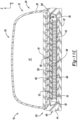
- the second surface 601j may extend upwardly along the Z-axis to define in part a flange portion 118 of the foam structure 60j. Additionally, with reference to FIG. 12C , the second surface 601j of the foam structure 60j may be substantially concave in a direction extending alone the X-axis. In this regard, the concavity of the second surface 601j may be equal to, and match, the convexity of the second surface 53j of the first barrier layer 52j. Accordingly, the fourth attachment 102j may be such that the entire first surface 601j of the foam structure 60j contacts the surface 53j of the first barrier layer 52j.
- the attachment 94k between the tensile member 72k (at the first substrate 82k) and the first barrier layer 52, as well as the attachment 104k between the tensile member 72k (at the second substrate 84k) and the second barrier layer 54, may be formed in a manner such that substantially all of the first and second substrates 82k, 84k contact the first and second surfaces 55, 53, respectively.
- the attachment 94m between the tensile member 72m (at the first substrate 82m) and the first barrier layer 52m, as well as the attachment 104m between the tensile member 72m (at the second substrate 84m) and the second barrier layer 54m, may be formed in a manner such that substantially all of the first and second substrates 82m, 84m contact the first and second surfaces 55m, 53m, respectively.
- a second tensile member 74m of the tensile members 70m may be disposed within the first passage 130m1 adjacent to the second barrier layer 54m such that the second substrate 84m of the second tensile member 74m engages the first surface 55m of the second barrier layer 54m at a fifth attachment 104m and is substantially flush with the second substrate 84m of the first tensile member 72m.
- the second substrate 84m of the second tensile member 74m may include a substantially planar configuration.
- the attachment 104m between the third tensile member 76m (at the second substrate 84m) and the second barrier layer 54m may be formed in a manner such that substantially all of the second substrate 84m of the third tensile member 76m contacts the first surface 55m of the second barrier layer 54m.
- a fourth tensile member 78m of the tensile members 70m may be disposed within the third passage 130m3 adjacent to the second barrier layer 54m such that the second substrate 84m of the fourth tensile member 78m engages the first surface 55m of the second barrier layer 54m at a fifth attachment 104m and is substantially flush with the second substrate 84m of the first tensile member 72m.
- the second substrate 84m of the fourth tensile member 78m may include a substantially planar configuration.
- a distance along the Z-axis between the first and second substrates 82m, 84m of the first tensile member 72m may be substantially equal to a distance along the Z-axis between the second surface 601m of the second foam structure 64m and the second substrate 84m of the third tensile member 76m.
- the first substrate 82m of the third tensile member 76m may include a substantially planar configuration. Accordingly, the attachment 106m between the third tensile member 76m (at the first substrate 82m) and the second foam structure 64m may be formed in a manner such that substantially all of the first substrate 82m contacts the first surface 602m of the second foam structure 64m. Additionally, the attachment 102m may be such that substantially the entire first surface 601m of the second foam structure 64m contacts the surface 53m of the first barrier layer 52m.
- Clause 4 The fluid-filled chamber of Clause 3, wherein the tensile member is attached to the foam structure.
Landscapes
- Engineering & Computer Science (AREA)
- Mechanical Engineering (AREA)
- Ceramic Engineering (AREA)
- Footwear And Its Accessory, Manufacturing Method And Apparatuses (AREA)
Abstract
Description
- This application claims priority to
U.S. Patent Application Serial No. 14/863,753, filed September 24, 2015 - The present disclosure relates generally to articles of footwear and more specifically to a fluid-filled chamber for use with an article of footwear and a method for making a fluid-filled chamber.
- This section provides background information related to the present disclosure and is not necessarily prior art.
- Articles of footwear typically include a sole structure that provides a layer between the foot on which the article of footwear is worn and a ground surface. The sole structure prevents the foot from contacting the ground surface and provides a degree of cushioning to the foot during use. The sole structure typically includes an outsole that contacts the ground surface and a midsole that supports, stabilizes, and cushions the foot. A polymer foam material may form the midsole to provide a level of cushioning that minimizes the forces felt by the foot when the outsole strikes the ground surface.
- While traditional midsole materials, such as polymer foam materials, provide a degree of comfort and stability, such polymer foam materials are typically tailored to provide a specific type of cushioning and are generally limited in that regard. For example, stiffer foam materials provide a more responsive feel during use but are less capable of absorbing impacts. Conversely, softer materials are less responsive but provide a greater degree of cushioning and are therefore better suited than stiffer materials for applications that favor impact absorption over responsiveness. Accordingly, providing a sole structure with more than one type of cushioning system provides an article of footwear with both a responsive feel and the ability to absorb impacts during use.
- In an effort to balance responsiveness and cushioning, footwear manufacturers typically provide a sole structure with more than one type of cushioning. For example, a midsole may be formed from a polymer foam material that is used in conjunction with rubber posts or resilient members. The posts provide a responsive feel during use while the polymer foam provides cushioning. While rubber posts or other resilient members may be used in conjunction with polymer foam, other cushioning systems such as fluid-filled bladders may alternatively be used in conjunction with polymer foam depending on the particular application.
- While sole structures of conventional articles of footwear may include more than one type of cushioning system, such systems are typically separate and independent from one another. Accordingly, these systems separately provide the article of footwear with responsiveness and cushioning and only cooperate with one another once assembled into the sole structure.
- The drawings described herein are for illustrative purposes only of selected configurations and are not intended to limit the scope of the present disclosure.
-
FIG. 1A is a top perspective view of an article of footwear in accordance with principles of the present disclosure; -
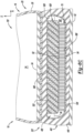
FIG. 1B is a partial cross-sectional view of the article of footwear ofFIG. 1A taken along theline 1B-1B ofFIG. 1A ; -
FIG. 2A is a side elevation view of the article of footwear ofFIG. 1A ; -
FIG. 2B is a side elevation view of another article of footwear in accordance with the principles of the present disclosure; -
FIG. 2C is a side elevation view of another article of footwear in accordance with the principles of the present disclosure; -
FIG. 2D is a side elevation view of another article of footwear in accordance with the principles of the present disclosure; -
FIG. 3A is a top perspective view of an article of footwear in accordance with principles of the present disclosure; -
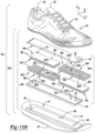
FIG. 3B is an exploded view of the article of footwear ofFIG. 3A ; -
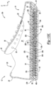
FIG. 3C is a cross-sectional view of the article of footwear ofFIG. 3A taken along theline 3C-3C ofFIG. 3A ; -
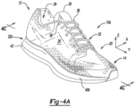
FIG. 4A is a top perspective view of an article of footwear in accordance with principles of the present disclosure; -
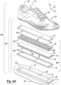
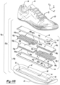
FIG. 4B is an exploded view of the article of footwear ofFIG. 4A ; -
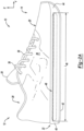
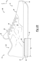
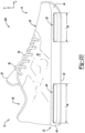
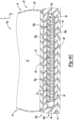
FIG. 4C is a cross-sectional view of the article of footwear ofFIG. 4A taken along theline 4C-4C ofFIG. 4A ; -
FIG. 5A is a top perspective view of an article of footwear in accordance with principles of the present disclosure; -
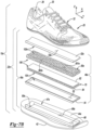
FIG. 5B is an exploded view of the article of footwear ofFIG. 5A ; -
FIG. 5C is a cross-sectional view of the article of footwear ofFIG. 5A taken along theline 5C-5C ofFIG. 5A ; -
FIG. 6A is a top perspective view of an article of footwear in accordance with principles of the present disclosure; -
FIG. 6B is an exploded view of the article of footwear ofFIG. 6A ; -
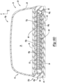
FIG. 6C is a cross-sectional view of the article of footwear ofFIG. 6A taken along theline 6C-6C ofFIG. 6A ; -
FIG. 7A is a top perspective view of an article of footwear in accordance with principles of the present disclosure; -
FIG. 7B is an exploded view of the article of footwear ofFIG. 7A ; -
FIG. 7C is a partial cross-sectional view of the article of footwear ofFIG. 7A taken along theline 7C-7C ofFIG. 7A ; -
FIG. 7D is a cross-sectional view of the article of footwear ofFIG. 7A taken along theline 7D-7D ofFIG. 7A ; -
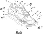
FIG. 8A is a top perspective view of an article of footwear in accordance with principles of the present disclosure; -
FIG. 8B is an exploded view of the article of footwear ofFIG. 8A ; -
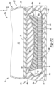
FIG. 8C is a partial cross-sectional view of the article of footwear ofFIG. 8A taken along theline 8C-8C ofFIG. 8A ; -
FIG. 8D is a cross-sectional view of the article of footwear ofFIG. 8A taken along theline 8D-8D ofFIG. 8A ; -
FIG. 9A is a top perspective view of an article of footwear in accordance with principles of the present disclosure; -
FIG. 9B is an exploded view of the article of footwear ofFIG. 9A ; -
FIG. 9C is a partial cross-sectional view of the article of footwear ofFIG. 9A taken along theline 9C-9C ofFIG. 9A ; -
FIG. 9D is a cross-sectional view of the article of footwear ofFIG. 9A taken along theline 9D-9D ofFIG. 9A ; -
FIG. 9E is a cross-sectional view of the article of footwear ofFIG. 9A taken along theline 9E-9E ofFIG. 9A ; -
FIG. 10A is a top perspective view of an article of footwear in accordance with principles of the present disclosure; -
FIG. 10B is an exploded view of the article of footwear ofFIG. 10A ; -
FIG. 10C is a partial cross-sectional view of the article of footwear ofFIG. 10A taken along theline 10C-10C ofFIG. 10A ; -
FIG. 10D is a cross-sectional view of the article of footwear ofFIG. 10A taken along theline 10D-10D ofFIG. 10A ; -
FIG. 10E is a cross-sectional view of the article of footwear ofFIG. 10A taken along theline 10E-10E ofFIG. 10A ; -
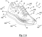
FIG. 11A is a top perspective view of an article of footwear in accordance with principles of the present disclosure; -
FIG. 11B is an exploded view of the article of footwear ofFIG. 11A ; -
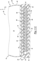
FIG. 11C is a partial cross-sectional view of the article of footwear ofFIG. 11A taken along theline 11C-11C ofFIG. 11A ; -
FIG. 11D is a cross-sectional view of the article of footwear ofFIG. 11A taken along theline 11D-11D ofFIG. 11A ; -
FIG. 11E is a cross-sectional view of the article of footwear ofFIG. 11A taken along theline 11E-11E ofFIG. 11A ; -
FIG. 11F is a cross-sectional view of the article of footwear ofFIG. 11A taken along theline 11F-11F ofFIG. 11A ; -
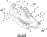
FIG. 12A is a top perspective view of an article of footwear in accordance with principles of the present disclosure; -
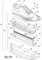
FIG. 12B is an exploded view of the article of footwear ofFIG. 12A ; -
FIG. 12C is a partial cross-sectional view of the article of footwear ofFIG. 12A taken along theline 12C-12C ofFIG. 12A ; -
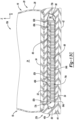
FIG. 12D is a cross-sectional view of the article of footwear ofFIG. 12A taken along theline 12D-12D ofFIG. 12A ; -
FIG. 13A is a top perspective view of an article of footwear in accordance with principles of the present disclosure; -
FIG. 13B is an exploded view of the article of footwear ofFIG. 13A ; -
FIG. 13C is a partial cross-sectional view of the article of footwear ofFIG. 13A taken along theline 13C-13C ofFIG. 13A ; -
FIG. 13D is a cross-sectional view of the article of footwear ofFIG. 13A taken along theline 13D-13D ofFIG. 13A ; -
FIG. 14A is a top perspective view of an article of footwear in accordance with principles of the present disclosure; -
FIG. 14B is an exploded view of the article of footwear ofFIG. 14A ; -
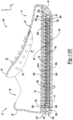
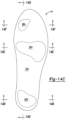
FIG. 14C is a top schematic view of a midsole of the article of footwear ofFIG. 14A ; -
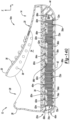
FIG. 14D is a partial cross-sectional view of the article of footwear ofFIG. 14A taken along theline 14D-14D ofFIG. 14C ; -
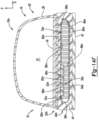
FIG. 14E is a cross-sectional view of the article of footwear ofFIG. 14A taken along theline 14E-14E ofFIG. 14C ; -
FIG. 14F is a cross-sectional view of the article of footwear ofFIG. 14A taken along theline 14F-14F ofFIG. 14C ; and -
FIG. 14G is a cross-sectional view of the article of footwear ofFIG. 14A taken along the line 14G-14G ofFIG. 14C . - Corresponding reference numerals indicate corresponding parts throughout the drawings.
- Example configurations will now be described more fully with reference to the accompanying drawings. Example configurations are provided so that this disclosure will be thorough, and will fully convey the scope of the disclosure to those of ordinary skill in the art. Specific details are set forth such as examples of specific components, devices, and methods, to provide a thorough understanding of configurations of the present disclosure. It will be apparent to those of ordinary skill in the art that specific details need not be employed, that example configurations may be embodied in many different forms, and that the specific details and the example configurations should not be construed to limit the scope of the disclosure.
- The terminology used herein is for the purpose of describing particular exemplary configurations only and is not intended to be limiting. As used herein, the singular articles "a," "an," and "the" may be intended to include the plural forms as well, unless the context clearly indicates otherwise. The terms "comprises," "comprising," "including," and "having," are inclusive and therefore specify the presence of features, steps, operations, elements, and/or components, but do not preclude the presence or addition of one or more other features, steps, operations, elements, components, and/or groups thereof. The method steps, processes, and operations described herein are not to be construed as necessarily requiring their performance in the particular order discussed or illustrated, unless specifically identified as an order of performance. Additional or alternative steps may be employed.
- When an element or layer is referred to as being "on," "engaged to," "connected to," "attached to," or "coupled to" another element or layer, it may be directly on, engaged, connected, attached, or coupled to the other element or layer, or intervening elements or layers may be present. In contrast, when an element is referred to as being "directly on," "directly engaged to," "directly connected to," "directly attached to," or "directly coupled to" another element or layer, there may be no intervening elements or layers present. Other words used to describe the relationship between elements should be interpreted in a like fashion (e.g., "between" versus "directly between," "adjacent" versus "directly adjacent," etc.). As used herein, the term "and/or" includes any and all combinations of one or more of the associated listed items.
- The terms first, second, third, etc. may be used herein to describe various elements, components, regions, layers and/or sections. These elements, components, regions, layers and/or sections should not be limited by these terms. These terms may be only used to distinguish one element, component, region, layer or section from another region, layer or section. Terms such as "first," "second," and other numerical terms do not imply a sequence or order unless clearly indicated by the context. Thus, a first element, component, region, layer or section discussed below could be termed a second element, component, region, layer or section without departing from the teachings of the example configurations.
- In one configuration, a fluid-filled chamber is provided and includes a first barrier layer, a second barrier layer, a foam structure, and a tensile member. The second barrier layer is secured to the first barrier layer to define an interior void between the first barrier layer and the second barrier layer. The interior void contains a predetermined volume of fluid. The foam structure and the tensile member are disposed within the interior void, whereby the tensile member includes a plurality of fibers extending in a first direction between the first barrier layer and the second barrier layer.
- Implementations of the disclosure may include one or more of the following optional features. In some implementations, the tensile member is disposed between the foam structure and one of the first barrier layer and the second barrier layer. In some examples, the tensile member is attached to one of the first barrier layer and the second barrier layer, the foam structure is attached to the other of the first barrier layer and the second barrier layer, and/or the tensile member is attached to the foam structure.
- The foam structure may be attached to the tensile member at an attachment location that is spaced apart from the first barrier layer and the second barrier layer.
- In some configurations, the foam structure includes a first foam layer and a second foam layer. The first foam layer may be attached to the first barrier layer and the second foam layer may be attached to the second barrier layer. In some implementations, the tensile member may be disposed between the first foam layer and the second foam layer.
- Additionally or alternatively, the tensile member may include a first substrate and a second substrate. The plurality of fibers may extend between and may be attached to the first substrate and the second substrate. In some examples, the first substrate may be attached to one of the first barrier layer and the second barrier layer and the second substrate may be attached to the foam layer.
- A method is also provided and includes forming a first barrier layer, forming a second barrier layer, and securing the first barrier layer to the second barrier layer to define an interior void disposed between the first barrier layer and the second barrier layer. The method additionally includes positioning a foam structure within the interior void, positioning a tensile member having a first substrate, a second substrate, and a plurality of fibers extending between the first substrate and the second substrate within the interior void and between the foam structure and one of the first barrier layer and the second barrier layer, and providing the interior void with a predetermined volume of fluid.
- In one configuration, positioning the tensile member between the foam structure and one of the first barrier layer and the second barrier layer includes attaching one of the first substrate and the second substrate to the foam structure.
- The method may additionally include attaching one of the first substrate and the second substrate to the one of the first barrier layer and the second barrier layer and attaching the foam structure to the other of the first barrier layer and the second barrier layer.
- The tensile member may be attached to the foam structure. Further, the foam structure may be attached to the tensile member at an attachment location. Attaching the foam structure to the tensile member at an attachment location may include attaching the foam structure to the tensile member at an attachment location that is spaced apart from the first barrier layer and the second barrier layer.
- Positioning the foam structure may include positioning a first foam layer and positioning a second foam layer. The method may additionally include attaching the first foam layer to the first barrier layer and attaching the second foam layer to the second barrier layer, wherein positioning the tensile member includes positioning the tensile member between the first foam layer and the second foam layer. The method may also include attaching one of the first substrate and the second substrate to the first foam layer and attaching the other of the first substrate and the second substrate to the second foam layer.
- In one configuration, the method may include providing the foam structure with an arcuate surface and, further, may include attaching the arcuate surface to one of the first barrier layer and the second barrier layer.
- Referring to
FIGS. 1A-1B , an article offootwear 10 is provided and may include an upper 20 and asole structure 22. Thesole structure 22 may be attached to the upper 20 and positioned between the upper 20 and a ground surface in a manner that prevents the upper 20 from contacting the ground surface during normal use of the article offootwear 10. - The upper 20 and the
sole structure 22 may extend from aheel end 12 to aforefoot end 14 along a Y-axis, and from alateral side 16 to amedial side 18 along an X-axis. Theheel end 12 may correspond with rear portions of a foot, including a calcaneus bone. Theforefoot end 14 may correspond with toes and joints connecting metatarsal bones with phalanx bones of the foot. The lateral andmedial sides footwear 10 extending from theheel end 12 to theforefoot end 14. - The upper 20 may include a
body 26, atongue 30, afastening system 32, and asockliner 34. Different materials may form thebody 26 of the upper 20, including one or more of foam, textiles, leather, and synthetic leather that connect together to form a shape of the upper 20. In this regard, thebody 26 may be formed from one or more materials that are stitched or adhesively bonded together to form afootwear cavity 24 that receives and secures a foot for support on thesole structure 22. Suitable materials for thebody 26 may include, but are not limited to, textiles, foam, leather, and synthetic leather. The materials may be selected and located to impart properties of durability, air-permeability, wear-resistance, flexibility, and comfort to the foot while disposed within thefootwear cavity 24. - The
body 26 of the upper 20 may be formed to define a foot-receivingopening 28 in theheel end 12 of the upper 20. The foot-receivingopening 28 may provide access to thefootwear cavity 24. For example, the foot-receivingopening 28 may receive a foot to secure the foot within thefootwear cavity 24 and facilitate entry and removal of the foot from and to thefootwear cavity 24. Thebody 26 and the foot-receivingopening 28 may vary from what is illustrated inFIGS. 1A-1B without departing from the scope of the present disclosure. For example, in some configurations, thebody 26 may constitute less material and the foot-receivingopening 28 may be larger and/or of a different shape. - The
tongue 30 may extend between thefootwear cavity 24 and thefastening system 32. Similar to thebody 26 of the upper 20, thetongue 30 may consist of different materials connected together. In this regard, thetongue 30 may be formed separately from, but attached to, thebody 26 in a manner that allows a user of the article offootwear 10 to modify the dimensions of the foot-receivingopening 28. For example, the user of the article offootwear 10 may manipulate the position of thetongue 30 to allow his or her foot to easily enter into or exit from thefootwear cavity 24 through the foot-receivingopening 28. - The
fastening system 32 may include one or more fasteners (e.g., lace 36) extending along the upper 20. In some configurations, the upper 20 may include apertures such asapertures 38 and/or other engagement features such as fabric or mesh loops that receive the fasteners. A user of the article offootwear 10 may tighten or loosen the fasteners through the plurality ofapertures 38 in order to tighten or loosen thebody 26 andtongue 30 of the upper 20 around the user's foot or to allow his or her foot to enter into or exit from thefootwear cavity 24. While the fasteners are generally shown and described herein as thelace 36, it will be appreciated that the fasteners may include straps, cords, hook-and-loop, or any other suitable type of fastener, within the scope of the present disclosure. - The
sockliner 34 may be located within thefootwear cavity 24 along a portion of thebody 26 of the upper 20. In some configurations, thesockliner 34 resides in a location within thefootwear cavity 24 to contact a plantar surface of the user's foot in order to enhance the comfort of the article offootwear 10. - While the article of
footwear 10 is shown and described herein as including thetongue 30, thefastening system 32, and thesockliner 34, it will be appreciated that thetongue 30, thefastening system 32, and thesockliner 34 are optional features of the article offootwear 10. Moreover, the size, shape, location, and other characteristics of each may vary greatly between different implementations of the article offootwear 10. - The
sole structure 22 may include different layers, such as anoutsole 42, amidsole 40, and an insole orsockliner 34, for example. Each layer may serve a particular function. For example, the insole orsockliner 34 may be designed to contact the foot and to provide enhanced comfort to the foot, as described above. In this regard, theinsole 34 may include a layer formed into thesole structure 22 such that theinsole 34 is disposed between themidsole 40 and the upper 20 in an assembled configuration. - The
outsole 42 is generally positioned on a bottom surface of the article offootwear 10. In particular, theoutsole 42 may include a layer coupled to themidsole 40, such that theoutsole 42 contacts the ground surface during normal use. In this regard, theoutsole 42 may provide a degree of cushioning to the foot during use of the article offootwear 10. Further, theoutsole 42 may be formed from an abrasive-resistant material such as rubber to protect the article offootwear 10 and provide the article offootwear 10 with the ability to positively grip the ground surface during use. - The
midsole 40 may include abody 44 and one or more fluid-filledchambers 46, and may be disposed between theoutsole 42 and the upper 20 and/or theinsole 34. In some configurations, themidsole 40 may extend between theheel end 12 and theforefoot end 14 along the Y-axis and between thelateral side 16 and themedial side 18 along the X-axis in order to improve various performance-related characteristics of the article offootwear 10. For example, themidsole 40 may provide both stability and a cushioning system for the user's foot. - The
body 44 of themidsole 40 may be formed at least in part from a foam polymer material, such as polyurethane, ethylvinylacetate, or another material, and may include a cavity 47 (FIG. 3B ) defined at least in part by a first (e.g., upper)chamber contact surface 86, a second (e.g., lower)chamber contact surface 88, and a third (e.g., side or peripheral) chamber contact surface 90 (each shown, for example, inFIGS. 3B and3C ). - The fluid-filled
chamber 46 may be disposed within thecavity 47 of thebody 44 and may include afirst barrier layer 52, asecond barrier layer 54, a foam structure (e.g., layer) 60, and atensile member 70. Thefirst barrier layer 52 may be coupled to thesecond barrier layer 54 at aseam 56. In some configurations, thefirst barrier layer 52 is sealed to thesecond barrier layer 54 at theseam 56 such that the first and second barrier layers 52, 54 collectively define aninterior void 58. Theinterior void 58 may include one or more fluids. For example, air, nitrogen, hexafluorethane, sulfur hexafluoroide, other gases, other fluids, or a mixture thereof, may fill the fluid-filledchamber 46. The first and second barrier layers 52, 54, including the sealedseam 56 therebetween, may maintain the fluid within theinterior void 58 at ambient pressure or, alternatively, may maintain the fluid within theinterior void 58 at a pressure that is greater than ambient pressure. The fluid-filledchamber 46, including the pressure thereof, provides improved cushioning properties by absorbing impact forces created when theoutsole 42 strikes the ground surface during use. - In some configurations, the fluid-filled
chamber 46 may extend along the X-axis by a width W46 and be substantially centered within thebody 44 of themidsole 40 along both the Z and X-axes. The width W46 of the fluid-filledchamber 46 may extend across a majority (e.g., greater than 50% and less than 100%) of themidsole 40 along the X-axis. In this regard, it will be appreciated that the width W46 of the fluid-filledchamber 46 may be greater or less than the width W46 shown inFIG. 1B without departing from the scope of this disclosure. - The configuration (e.g., size, position, and/or quantity) of the fluid-filled
chamber 46 within thebody 44 of themidsole 40 may vary from the position illustrated inFIGS. 1B and2A without departing from the scope of this disclosure. For example, the fluid-filledchamber 46 may be positioned off-center relative to thebody 44 along the X, Y, and/or Z-axes. Additionally, themidsole 40 may incorporate more than one fluid-filledchamber 46 having differing designs within the scope of the present disclosure. As illustrated inFIG. 2A , in some configurations, the fluid-filledchamber 46 includes a length L46 that spans from theheel end 12 to theforefoot end 14 along the Y-axis of the article offootwear 10. - As illustrated in
FIG. 2B , an article offootwear 100 is provided and includes a fluid-filledchamber 48. The article offootwear 100 and the fluid-filledchamber 48 may be substantially similar to the article offootwear 10 and the fluid filledchamber 46, respectively, except as otherwise shown or described herein. The fluid-filledchamber 48 may be disposed within theheel end 12 of the article offootwear 100 and may have a length L48 that spans only a portion of the distance between the heel and forefoot ends 12, 14 along the Y-axis. - As illustrated in
FIG. 2C , an article offootwear 200 is provided and includes a fluid-filledchamber 50. The article offootwear 200 and the fluid-filledchamber 50 may be substantially similar to the article offootwear 10 and the fluid filledchamber 46, respectively, except as otherwise shown or described herein. The fluid-filledchamber 50 may be disposed within theforefoot end 14 of the article offootwear 200 and may have a length L50 that spans only a portion of the distance between the heel and forefoot ends 12, 14 along the Y-axis. - As illustrated in
FIG. 2D , an article offootwear 300 is provided and includes the fluid-filledchamber 48 and the fluid-filledchamber 50. The article offootwear 300 may be substantially similar to the article offootwear 10 except as otherwise shown or described herein. While the articles offootwear chambers chambers - The
foam structure 60 may be disposed within theinterior void 58 of the fluid-filledchamber 46. As illustrated inFIG. 1B , in some configurations, thefoam structure 60 may be disposed adjacent to thesecond barrier layer 54 such that a first (e.g., lower)surface 602 of thefoam structure 60 engages a first (e.g., upper) surface 55 of thesecond barrier layer 54 at afirst attachment 96. Thefoam structure 60 may be formed from an open-cell foam core, such as the open-cell foam core disclosed inU.S. Patent Numbers 4,874,640 and5,235,715 , the disclosures of which are fully incorporated herein by reference. Alternatively, thefoam structure 60 may be formed from one or more flexible materials such as a mesh material, a nylon material, ethylene-vinyl acetate copolymer, or any other suitable material that provides cushioning and can be shaped into the shape of thefoam structure 60. The material of thefoam structure 60 provides improved cushioning properties by absorbing the impact forces created when theoutsole 42 strikes the ground surface during use. Utilization of high density foam may increase the strength of thefoam structure 60 and increase the length of time over which the impact forces are spread when theoutsole 42 strikes the ground surface. Further, combining thefoam structure 60 with the fluid-filledchamber 46 provides the article offootwear 10 with both responsive-type cushioning due to thefoam structure 60 and soft-type cushioning due to the fluid contained within thechamber 46. These components advantageously can be installed in the article offootwear 10 at the same time once the fluid-filledchamber 46 is formed. - With reference to
FIG. 3C , thetensile member 70 may be disposed within theinterior void 58 of the fluid-filledchamber 46 and may include a first (e.g., upper)substrate 82, a second (e.g., lower)substrate 84, and a plurality of individualtensile fibers 85 extending between thefirst substrate 82 and thesecond substrate 84. As illustrated inFIGS. 1B and3B , in some configurations, thetensile member 70 is disposed between thefoam structure 60 and thefirst barrier layer 52 relative to the Z-axis such that (i) thefirst substrate 82 engages a second (e.g., lower)surface 53 of thefirst barrier layer 52 at asecond attachment 94 and (ii) thesecond substrate 84 engages a second (e.g., upper)surface 601 of thefoam structure 60 at athird attachment 97. The first andsecond substrates attachment 94 between the tensile member 70 (at the first substrate 82) and thefirst barrier layer 52, as well as theattachment 97 between the tensile member 70 (at the second substrate 84) and thefoam structure 60, may be formed in a manner such that substantially all of the first andsecond substrates second surface 53 of thefirst barrier layer 52 and thesecond surface 601 of thefoam structure 60, respectively. - The plurality of individual
tensile fibers 85, which may deflect easily when a compressive force is applied to thetensile member 70, may include various sizes (e.g., diameter, length along the Z-axis), cross-sectional shapes (e.g., circular, rectangular, or other polygon), and/or materials. For example, as illustrated throughout the figures, a distance along the Z-axis between the first andsecond substrates tensile fibers 85, as measured along the Z-axis, may also vary from onetensile fiber 85 to anothertensile fiber 85 and/or from one configuration of the fluid-filledchamber 46 to another configuration of the fluid-filledchamber 46. When the fluid-filledchamber 46 and/or thetensile member 70 is in a neutral state (i.e., no external force is applied to the fluid-filledchamber 46 and/or the tensile member 70), one or more of the plurality of individualtensile fibers 85 may experience a tensile force in order to maintain a desired shape (e.g.,FIG. 1B ) of the fluid-filledchamber 46 by preventing or inhibiting thefirst barrier layer 52 from moving away from thesecond barrier layer 54 along the Z-axis. Thetensile fibers 85 are placed under tension due to the fluid contained within the fluid-filledchamber 46. Additional details oftensile fibers 85 are described inU.S. Patent Numbers 4,906,502 ,5,083,361 , and6,385,864 , the disclosures of which are fully incorporated herein by reference. - With further reference to
FIGS. 3A-3C , a method of manufacturing the article offootwear 10 will now be described. The first and/or second barrier layers 52, 54 may be formed from a polymer (e.g., thermoplastic polyurethane) using various manufacturing techniques (e.g., injection molding). Thefirst barrier layer 52 may be sealingly engaged with thesecond barrier layer 54 at theseam 56 such that the first and second barrier layers 52, 54 collectively define aninterior void 58. In particular, thefirst barrier layer 52 may be attached to thesecond barrier layer 54 using various fastening techniques, such as applying heat and/or pressure or applying an adhesive, for example. Thefoam structure 60 and thetensile member 70 may be positioned within theinterior void 58 such that the plurality offibers 85 extend in a first direction (e.g., along the Z-axis) between thefirst barrier layer 52 and thesecond barrier layer 54. In this regard, thefoam structure 60 may be attached to thesecond barrier layer 52 at thefirst attachment 96. In addition, thefirst substrate 82 may be attached to thefirst barrier layer 52 at thesecond attachment 94, and thesecond substrate 84 may be attached to thefoam structure 60 at thethird attachment 97. A predetermined volume of fluid, such as air, nitrogen, hexafluorethane, sulfur hexafluoride, or a mixture thereof, for example, may be injected into theinterior void 58 in order to place thefibers 85 in tension. The fluid-filledchamber 46 may be placed and secured within thebody 44 of themidsole 22. In particular, the fluid-filledchamber 46 may be secured within thecavity 47 using various techniques, such as overmolding or adhesive bonding, for example. - With reference to
FIGS. 4A-4C , another article offootwear 10b is shown. Except as otherwise provided herein, the structure and function of the article offootwear 10b may be substantially similar to the structure and function of the article offootwear 10. In view of the substantial similarity in structure and function of the components associated with the article offootwear 10b with respect to the article offootwear 10, like reference numerals are used hereinafter and in the drawings to identify like components, while like reference numerals containing letter extensions are used to identify those components that have been modified. - The article of
footwear 10b may include the upper 20 and asole structure 22b. Thesole structure 22b may include amidsole 40b and theoutsole 42. Themidsole 40b may include a fluid-filledchamber 46b residing within thebody 44. - The fluid-filled
chamber 46b may be located within the article offootwear 10b in any of the positions and orientations shown inFIGS. 2A-2D , and may include thefirst barrier layer 52, thesecond barrier layer 54, thefoam structure 60, and thetensile member 70. Thefoam structure 60 may be disposed adjacent to thefirst barrier layer 52 such that thesecond surface 601 of thefoam structure 60 engages thesecond surface 53 of thefirst barrier layer 52 at afourth attachment 102. Thetensile member 70 may be disposed between thefoam structure 60 and thesecond barrier layer 54 relative to the Z-axis such that (i) thesecond substrate 84 engages thefirst surface 55 of thesecond barrier layer 54 at afifth attachment 104 and (ii) thefirst substrate 82 engages thefirst surface 602 of thefoam structure 60 at asixth attachment 106. The first andsecond substrates attachment 106 between the tensile member 70 (at the first substrate 82) and thefoam structure 60, as well as theattachment 104 between the tensile member 70 (at the second substrate 84) and thesecond barrier layer 54, may be formed in a manner such that substantially all of the first andsecond substrates first surface 602 of thefoam structure 60 and thefirst surface 55 of thesecond barrier layer 54, respectively. Additionally, theattachment 102 may be such that substantially all of thefirst surface 601 of thefoam structure 60 contacts thesurface 53 of thefirst barrier layer 52. - With further reference to
FIGS. 4A-4C , a method of manufacturing the article offootwear 10b will now be described. In view of the substantial similarities in the method of manufacturing the article offootwear 10b and the method of manufacturing the article offootwear 10, only the differences will be discussed herein. During the method of manufacturing the article offootwear 10b, thefoam structure 60 may be attached to thefirst barrier layer 52 at thefourth attachment 102, thefirst substrate 82 may be attached to thefoam structure 60 at thesixth attachment 106, and thesecond substrate 84 may be attached to thesecond barrier layer 54 at thefifth attachment 104. Once attached, the fluid-filledchamber 46b may be provided with a predetermined fluid to place thefibers 85 of thetensile member 70 under tension. - With reference to
FIGS. 5A-5C , another article offootwear 10c is shown. Except as otherwise provided herein, the structure and function of the article offootwear 10c may be substantially similar to the structure and function of the article offootwear 10. In view of the substantial similarity in structure and function of the components associated with the article offootwear 10c with respect to the article offootwear 10, like reference numerals are used hereinafter and in the drawings to identify like components, while like reference numerals containing letter extensions are used to identify those components that have been modified. - The article of
footwear 10c may include the upper 20 and asole structure 22c. Thesole structure 22c may include amidsole 40c and theoutsole 42. Themidsole 40c may include a fluid-filledchamber 46c residing within thebody 44. - The fluid-filled
chamber 46c may be located within the article offootwear 10c in any of the positions and orientations shown inFIGS. 2A-2D , and may include thefirst barrier layer 52, thesecond barrier layer 54, thefoam structure 60, and one or moretensile members 70. As illustrated inFIG. 5B , in some configurations, the fluid-filledchamber 46c includes twotensile members 70. A first (e.g., upper)tensile member 72 of thetensile members 70 may be disposed between thefoam structure 60 and thefirst barrier layer 52 relative to the Z-axis such that (i) thefirst substrate 82 engages thesecond surface 53 of thefirst barrier layer 52 at thesecond attachment 94 and (ii) thesecond substrate 84 engages thesecond surface 601 of thefoam structure 60 at thethird attachment 97. A second (e.g., lower)tensile member 74 of thetensile members 70 may be disposed between thefoam structure 60 and thesecond barrier layer 54 relative to the Z-axis such that (i) thesecond substrate 84 engages thefirst surface 55 of thesecond barrier layer 54 at thefifth attachment 104 and (ii) thefirst substrate 82 engages thefirst surface 602 of thefoam structure 60 at thesixth attachment 106. Accordingly, as illustrated inFIGS. 5B and5C , thefoam structure 60 may be disposed between the first and secondtensile members second surface 601 engages thesecond substrate 84 of the firsttensile member 72 and thefirst surface 602 engages thefirst substrate 82 of the secondtensile member 74. - With further reference to
FIGS. 5A-5C , a method of manufacturing the article offootwear 10c will now be described. In view of the substantial similarities in the method of manufacturing the article offootwear 10c and the method of manufacturing the article offootwear 10, only the differences will be discussed herein. During the method of manufacturing the article offootwear 10c, thefoam structure 60 may be positioned between, and attached to, the first and secondtensile members second substrate 84 of the firsttensile member 72 may be attached to thesecond surface 601 of thefoam structure 60 at thethird attachment 97, and thefirst substrate 82 of the secondtensile member 74 may be attached to thefirst surface 602 of thefoam structure 60 at thesixth attachment 106. Additionally, thefirst substrate 82 of the firsttensile member 72 may be attached to thefirst barrier layer 52 at thesecond attachment 94, and thesecond substrate 84 of the secondtensile member 74 may be attached to thesecond barrier layer 54 at thefifth attachment 104. - With reference to
FIGS. 6A-6C , another article offootwear 10d is shown. Except as otherwise provided herein, the structure and function of the article offootwear 10d may be substantially similar to the structure and function of the article offootwear 10. In view of the substantial similarity in structure and function of the components associated with the article offootwear 10d with respect to the article offootwear 10, like reference numerals are used hereinafter and in the drawings to identify like components, while like reference numerals containing letter extensions are used to identify those components that have been modified. - The article of
footwear 10d may include the upper 20 and asole structure 22d. Thesole structure 22d may include amidsole 40d and theoutsole 42. Themidsole 40d may include a fluid-filledchamber 46d residing within thebody 44. - The fluid-filled
chamber 46d may be located within the article offootwear 10d in any of the positions and orientations shown inFIGS. 2A-2D , and may include thefirst barrier layer 52, thesecond barrier layer 54, one ormore foam structures 60, and thetensile member 70. As illustrated inFIG. 6B , in some configurations, the fluid-filledchamber 46d includes twofoam structures 60. A first (e.g., upper)foam structure 62 of thefoam structures 60 may be disposed adjacent to thefirst barrier layer 52 such that thesecond surface 601 of thefoam structure 60 engages thesecond surface 53 of thefirst barrier layer 52 at thefourth attachment 102. A second (e.g., lower)foam structure 64 of thefoam structures 60 may be disposed adjacent to thesecond barrier layer 54 such that thefirst surface 602 of thefoam structure 60 engages thefirst surface 55 of thesecond barrier layer 54 at thefirst attachment 96. Accordingly, as illustrated inFIGS. 6B and6C , thetensile member 70 may be disposed between the first andsecond foam structures 66, 64, such that thefirst substrate 82 engages thefirst surface 602 of thefirst foam structure 62 and thesecond substrate 84 engages thesecond surface 601 of thesecond foam structure 64. - With further reference to
FIGS. 6A-6C , a method of manufacturing the article offootwear 10d will now be described. In view of the substantial similarities in the method of manufacturing the article offootwear 10d and the method of manufacturing the article offootwear 10, only the differences will be discussed herein. During the method of manufacturing the article offootwear 10d, thetensile member 70 may be positioned between, and attached to, the first andsecond foam structures second substrate 84 of thetensile member 70 may be attached to thesecond surface 601 of thesecond foam structure 64 at thethird attachment 97, and thefirst substrate 82 of thetensile member 70 may be attached to thefirst surface 602 of thefirst foam structure 62 at thesixth attachment 106. Additionally, thefirst surface 602 of thesecond foam structure 64 may be attached to thesecond barrier layer 54 at thefirst attachment 96, and thesecond surface 601 of thefirst foam structure 62 may be attached to thefirst barrier layer 52 at thefourth attachment 102. - With reference to
FIGS. 7A-7D , another article offootwear 10e is shown. Except as otherwise provided herein, the structure and function of the article offootwear 10e may be substantially similar to the structure and function of the article offootwear 10. In view of the substantial similarity in structure and function of the components associated with the article offootwear 10e with respect to the article offootwear 10, like reference numerals are used hereinafter and in the drawings to identify like components, while like reference numerals containing letter extensions are used to identify those components that have been modified. - The article of
footwear 10e may include the upper 20 and asole structure 22e. Thesole structure 22e may include amidsole 40e and theoutsole 42. Themidsole 40e may include a fluid-filledchamber 46e residing within abody 44e. As illustrated inFIGS. 7B-7D , thebody 44e may include acavity 47e defined at least in part by a first (e.g., upper)chamber contact surface 86e, the secondchamber contact surface 88, and the thirdchamber contact surface 90. The firstchamber contact surface 86e may be substantially convex in a direction extending alone the X-axis, and substantially planar in a direction extending along the Y-axis. - The fluid-filled
chamber 46e may be located within the article offootwear 10e in any of the positions and orientations shown inFIGS. 2A-2D , and may include a first barrier layer 52g, thesecond barrier layer 54, afoam structure 60e, and thetensile member 70. Asecond surface 53e of thefirst barrier layer 52e may be substantially convex in a direction extending alone the X-axis, and substantially planar in a direction extending alone the Y-axis. A surface of thefirst barrier layer 52e opposite thesecond surface 53e may be substantially concave in a direction extending alone the X-axis, and substantially planar in a direction extending alone the Y-axis. In this regard, the concavity of the surface opposite thesecond surface 53e may be equal to, and match, the convexity of the firstchamber contact surface 86e of thebody 44e. - The
foam structure 60e may be disposed within theinterior void 58e of the fluid-filledchamber 46e. As illustrated inFIGS. 7B and7C , in some configurations, thefoam structure 60e is disposed adjacent to thefirst barrier layer 52e such that asecond surface 601e of thefoam structure 60e engages thesecond surface 53e of thefirst barrier layer 52e at afourth attachment 102e. Thesecond surface 601e of thefoam structure 60e may be substantially concave in a direction extending alone the X-axis. In this regard, the concavity of thesecond surface 601e may be equal to, and match, the convexity of thesecond surface 53e of thefirst barrier layer 52e. Accordingly, thefourth attachment 102e may be such that substantially the entirefirst surface 601e of thefoam structure 60e contacts thesurface 53e of thefirst barrier layer 52e. Thetensile member 70 may be disposed between thefoam structure 60e and thesecond barrier layer 54 relative to the Z-axis such that (i) thesecond substrate 84 engages thefirst surface 55 of thesecond barrier layer 54 at thefifth attachment 104 and (ii) thefirst substrate 82 engages thefirst surface 602 of thefoam structure 60e at thesixth attachment 106. - With reference to
FIGS. 8A-8D , another article offootwear 10f is shown. Except as otherwise provided herein, the structure and function of the article offootwear 10f may be substantially similar to the structure and function of the article offootwear 10. In view of the substantial similarity in structure and function of the components associated with the article offootwear 10f with respect to the article offootwear 10, like reference numerals are used hereinafter and in the drawings to identify like components, while like reference numerals containing letter extensions are used to identify those components that have been modified. - The article of
footwear 10f may include the upper 20 and asole structure 22f. Thesole structure 22f may include amidsole 40f and theoutsole 42. Themidsole 40f may include a fluid-filledchamber 46f residing within abody 44f. As illustrated inFIG. 7B , the body 44g may include a cavity 47f defined at least in part by a first (e.g., upper)chamber contact surface 86f, a second (e.g., lower)chamber contact surface 88f, and a third (e.g., peripheral)chamber contact surface 90f. The firstchamber contact surface 86f may be substantially planar and include a transversely extending portion 110 (FIG. 8D ) proximate theheel end 12 of the article offootwear 10f. In some configurations, the firstchamber contact surface 86f may extend toward the secondchamber contact surface 88f from theheel end 12 to theforefoot end 14 along the Y-axis. For example, in some configurations the firstchamber contact surface 86f may be inclined toward the secondchamber contact surface 88f. In other configurations, the firstchamber contact surface 86f may include a concave shape extending toward the secondchamber contact surface 88f. As illustrated inFIG. 8D , the transversely extendingportion 110 may extend away from the secondchamber contact surface 88f in a direction generally parallel to the Z-axis. The secondchamber contact surface 88f may be substantially planar. The thirdchamber contact surface 90f may extend from and between the first and secondchamber contact surfaces chamber contact surface 90f may extend away from the secondchamber contact surface 88f by a greater distance at theheel end 12 than at theforefoot end 14. Accordingly, the thirdchamber contact surface 90f and the transversely extendingportion 110 of the firstchamber contact surface 86f may define a transversely extendingportion 112 of the cavity 47f. - The fluid-filled
chamber 46f may be located within the article offootwear 10f in any of the positions and orientations shown inFIGS. 2A-2D , and may include afirst barrier layer 52f, asecond barrier layer 54f, afoam structure 60f, and thetensile member 70. Asecond surface 53f of thefirst barrier layer 52f may include a size and shape that corresponds to, and matches, the size and shape of the first and thirdchamber contact surfaces body 44f. In this regard, as illustrated inFIG. 8D , thefirst barrier layer 52f may include aU-shaped portion 114 that is disposed within the transversely extendingportion 112 of the cavity 47f in the assembled configuration, such that theinterior void 58f includes a transversely extendingportion 116. - The
foam structure 60f may be disposed within theinterior void 58f of the fluid-filledchamber 46f. As illustrated inFIGS. 8B and8C , in some configurations, thefoam structure 60f is disposed adjacent to thefirst barrier layer 52f such that asecond surface 601f of thefoam structure 60f engages thesecond surface 53f of thefirst barrier layer 52f at a fourth attachment 102f. Thesecond surface 601f of thefoam structure 60f may include a size and shape that corresponds to, and matches, the size and shape of thesecond surface 53f of thefirst barrier layer 52f. In this regard, as illustrated inFIGS. 8B and8D , thesecond surface 601f may extend upwardly along the Z-axis to define in part aflange portion 118 of thefoam structure 60f. In the assembled configuration, theflange portion 118 may be disposed within the transversely extendingportion 116 of theinterior void 58f. Thetensile member 70 may be disposed between thefoam structure 60f and thesecond barrier layer 54f relative to the Z-axis such that (i) thesecond substrate 84 engages thefirst surface 55f of thesecond barrier layer 54f at afifth attachment 104f and (ii) thefirst substrate 82 engages thefirst surface 602f of thefoam structure 60f at asixth attachment 106f. - With reference to
FIGS. 9A-9E , another article offootwear 10g is shown. Except as otherwise provided herein, the structure and function of the article offootwear 10g may be substantially similar to the structure and function of the article offootwear 10. In view of the substantial similarity in structure and function of the components associated with the article offootwear 10g with respect to the article offootwear 10, like reference numerals are used hereinafter and in the drawings to identify like components, while like reference numerals containing letter extensions are used to identify those components that have been modified. - The article of
footwear 10g may include the upper 20 and asole structure 22g. Thesole structure 22g may include amidsole 40g and theoutsole 42. Themidsole 40g may include a fluid-filledchamber 46g residing within thebody 44. - The fluid-filled
chamber 46g may be located within the article offootwear 10g in any of the positions and orientations shown inFIGS. 2A-2D , and may include thefirst barrier layer 52, thesecond barrier layer 54, one ormore foam structures 60g, and one or moretensile members 70g. The first andsecond foam structures foam structures 60g may be disposed within the interior void 58g of the fluid-filledchamber 46g. As illustrated inFIG. 9E , thefirst foam structure 62g may be disposed adjacent to thefirst barrier layer 52 such that a second surface 601g of thefirst foam structure 62g engages thesecond surface 53 of thefirst barrier layer 52 at afourth attachment 102g. Thesecond foam structure 64g may be disposed adjacent to thesecond barrier layer 54 such that a first surface 602g of thesecond foam structure 62g engages thefirst surface 55 of thesecond barrier layer 54 at a first attachment 96g. - The first and second
tensile members tensile members 70g may be disposed within the interior void 58g of the fluid-filledchamber 46g. The firsttensile member 72g may be disposed between thesecond foam structure 64g and thefirst barrier layer 52 relative to the Z-axis such that (i) thefirst substrate 82g engages thesecond surface 53 of thefirst barrier layer 52 at asecond attachment 94g and (ii) thesecond substrate 84g engages the second surface 601g of thesecond foam structure 64g at athird attachment 97g. The secondtensile member 74g may be disposed between thefirst foam structure 62g and thefirst barrier layer 52 relative to the Z-axis such that (i) thesecond substrate 84 engages thefirst surface 55 of thesecond barrier layer 54 at afifth attachment 104g and (ii) thefirst substrate 82g engages the first surface 602g of thefirst foam structure 62g at asixth attachment 106g. - As illustrated in
FIG. 9E , thefirst foam structure 62g and the secondtensile member 74g may extend from theheel end 12 to anintermediate location 120 disposed between the heel and forefoot ends 12, 14, along the Y-axis. Thesecond foam structure 64g and the firsttensile member 72g may extend from theforefoot end 14 to theintermediate location 120 along the Y-axis. Accordingly, as illustrated, thefirst foam structure 62g may abut and/or oppose the firsttensile member 72g at theintermediate location 120, and thesecond foam structure 64g may abut and/or oppose the secondtensile member 74g at theintermediate location 120. If thefirst foam structure 62g abuts the firsttensile member 72g, theseelements second foam structure 64g abuts the secondtensile member 74g, theseelements - In some configurations, the
intermediate location 120 may be centrally located within the fluid-filledchamber 46g along the Y-axis, such that the lengths of the first andsecond foam structures tensile members intermediate location 120 may be offset from the center of the fluid-filledchamber 46g along the Y-axis such that the lengths of one or more of the first andsecond foam structures tensile members second foam structures tensile members - With reference to
FIGS. 10A-10E , another article offootwear 10h is shown. Except as otherwise provided herein, the structure and function of the article offootwear 10h may be substantially similar to the structure and function of the article offootwear 10. In view of the substantial similarity in structure and function of the components associated with the article offootwear 10h with respect to the article offootwear 10, like reference numerals are used hereinafter and in the drawings to identify like components, while like reference numerals containing letter extensions are used to identify those components that have been modified. - The article of
footwear 10h may include the upper 20 and asole structure 22h. Thesole structure 22h may include amidsole 40h and theoutsole 42. Themidsole 40h may include a fluid-filledchamber 46h residing within thebody 44. - The fluid-filled
chamber 46h may be located within the article offootwear 10h in any of the positions and orientations shown inFIGS. 2A-2D , and may include thefirst barrier layer 52, thesecond barrier layer 54, one ormore foam structures 60h, and one or moretensile members 70h. First andsecond foam structures foam structures 60h may be disposed within the interior void 58h of the fluid-filledchamber 46h. As illustrated inFIG. 10E , thefirst foam structure 62h may be disposed adjacent to thefirst barrier layer 52 such that asecond surface 601h of thefirst foam structure 62h engages thesecond surface 53 of thefirst barrier layer 52 at afourth attachment 102h. Thesecond foam structure 64h may be disposed adjacent to thesecond barrier layer 54 such that afirst surface 602h of thesecond foam structure 62h engages thefirst surface 55 of thesecond barrier layer 54 at afirst attachment 96h. - First and second
tensile members tensile members 70h may be disposed within the interior void 58h of the fluid-filledchamber 46h. The firsttensile member 72h may be disposed between thesecond foam structure 64h and thefirst barrier layer 52 relative to the Z-axis such that (i) thefirst substrate 82h engages thesecond surface 53 of thefirst barrier layer 52 at asecond attachment 94h and (ii) thesecond substrate 84h engages thesecond surface 601h of thesecond foam structure 64h at athird attachment 97h. The secondtensile member 74h may be disposed between thefirst foam structure 62h and thefirst barrier layer 52 relative to the Z-axis such that (i) thesecond substrate 84 engages thefirst surface 55 of thesecond barrier layer 54 at afifth attachment 104h and (ii) thefirst substrate 82h engages thefirst surface 602h of thefirst foam structure 62h at asixth attachment 106h. - As illustrated in
FIG. 10E , thefirst foam structure 62h and the secondtensile member 74h may extend from theforefoot end 14 to theintermediate location 120 along the Y-axis. Thesecond foam structure 64h and the firsttensile member 72h may extend from theheel end 12 to theintermediate location 120 along the Y-axis. Accordingly, as illustrated, thefirst foam structure 62h may abut and/or oppose the firsttensile member 72h at theintermediate location 120, and thesecond foam structure 64h may abut and/or oppose the secondtensile member 74h at theintermediate location 120. If thefirst foam structure 62h abuts the firsttensile member 72h, theseelements second foam structure 64h abuts the secondtensile member 74h, theseelements - With reference to
FIGS. 11A-11F , another article offootwear 10i is shown. Except as otherwise provided herein, the structure and function of the article offootwear 10i may be substantially similar to the structure and function of the article offootwear 10. In view of the substantial similarity in structure and function of the components associated with the article offootwear 10i with respect to the article offootwear 10, like reference numerals are used hereinafter and in the drawings to identify like components, while like reference numerals containing letter extensions are used to identify those components that have been modified. - The article of
footwear 10i may include the upper 20 and asole structure 22i. Thesole structure 22i may include amidsole 40i and theoutsole 42. Themidsole 40i may include a fluid-filledchamber 46i residing within thebody 44. - The fluid-filled
chamber 46i may be located within the article offootwear 10i in any of the positions and orientations shown inFIGS. 2A-2D , and may include thefirst barrier layer 52, thesecond barrier layer 54, one ormore foam structures 60i, and one or moretensile members 70i. First andsecond foam structures foam structures 60i may be disposed within the interior void 58i of the fluid-filledchamber 46i. As illustrated inFIG. 11F , the first andsecond foam structures first barrier layer 52 such that asecond surface 601i of each of the first andsecond foam structures second surface 53 of thefirst barrier layer 52 at a fourth attachment 102i. - First, second, and third
tensile members tensile members 70i may be disposed within the interior void 58i of the fluid-filledchamber 46i. The first and secondtensile members first barrier layer 52 and the first andsecond foam structures second substrate 84 of each of the first and secondtensile members first surface 55 of thesecond barrier layer 54 at afifth attachment 104i and (ii) thefirst substrate 82i of each of the first and secondtensile members first surface 602i of thefirst foam structure 62i at asixth attachment 106i. The thirdtensile member 76i may be disposed between the first andsecond foam structures tensile members first substrate 82i of the thirdtensile member 76i may engage thesecond surface 53 of thefirst barrier layer 52, and thesecond substrate 84i of the thirdtensile member 76i may engage thefirst surface 55 of thesecond barrier layer 52. In this regard, a height of the thirdtensile member 76i along the Z-axis may be substantially equal to (i) a combined height of thefirst foam structure 62i and the firsttensile member 72i, and (ii) a combined height of thesecond foam structure 64i and the secondtensile member 74i. - As illustrated in
FIG. 11F , thefirst foam structure 62i and the firsttensile member 72i may extend from theheel end 12 to a firstintermediate location 120i disposed between the heel and forefoot ends 12, 14, along the Y-axis. Thesecond foam structure 64i and the secondtensile member 74i may extend from theforefoot end 14 to a secondintermediate location 122 along the Y-axis. The thirdtensile member 76i may extend from the firstintermediate location 120 to the secondintermediate location 122. Accordingly, as illustrated, thefirst foam structure 62i and the firsttensile member 72i may abut and/or oppose a proximal end of the thirdtensile member 76i at the firstintermediate location 120, and thesecond foam structure 64i and the secondtensile member 74i may abut and/or oppose the thirdtensile member 76i at the secondintermediate location 122. Thefirst foam structure 62i and the firsttensile member 72i may be attached to the thirdtensile member 76i at the firstintermediate location 120, and thesecond foam structure 64i and the secondtensile member 74i may be attached to the thirdtensile member 76i at the secondintermediate location 122. - In some configurations, the first and/or second
intermediate locations chamber 46i along the Y-axis, such that the thirdtensile member 76i is disposed at the central portion of the fluid-filledchamber 46i along the Y-axis. In other configurations, one or more of the first and secondintermediate locations chamber 46i such that the thirdtensile member 76i is offset from the central portion of the fluid-filledchamber 46i relative to the Y-axis. - With reference to
FIGS. 12A-12D , another article offootwear 10j is shown. Except as otherwise provided herein, the structure and function of the article offootwear 10j may be substantially similar to the structure and function of the article offootwear 10. In view of the substantial similarity in structure and function of the components associated with the article offootwear 10j with respect to the article offootwear 10, like reference numerals are used hereinafter and in the drawings to identify like components, while like reference numerals containing letter extensions are used to identify those components that have been modified. - The article of
footwear 10j may include the upper 20 and asole structure 22j. Thesole structure 22j may include amidsole 40j and theoutsole 42. Themidsole 40j may include a fluid-filledchamber 46j residing within abody 44j. As illustrated inFIG. 12B , thebody 44j may include a cavity 47j defined at least in part by a first (e.g., upper)chamber contact surface 86j, a second (e.g., lower)chamber contact surface 88j, and a third (e.g., peripheral)chamber contact surface 90j. The firstchamber contact surface 86j may be substantially planar and include a transversely extending portion 110 (FIG. 12D ) proximate theheel end 12 of the article offootwear 10j. In some configurations, the firstchamber contact surface 86j may extend toward the secondchamber contact surface 88j from theheel end 12 to theforefoot end 14 along the Y-axis. For example, in some configurations the firstchamber contact surface 86j may be inclined toward the secondchamber contact surface 88f. In other configurations, the firstchamber contact surface 86j may include a concave shape extending toward the secondchamber contact surface 88f. As illustrated inFIG. 12D , the transversely extendingportion 110 may extend away from the secondchamber contact surface 88j in a direction generally parallel to the Z-axis. The secondchamber contact surface 88j may be substantially planar. The thirdchamber contact surface 90j may extend from and between the first and secondchamber contact surfaces chamber contact surface 90j may extend away from the secondchamber contact surface 88j by a greater distance at theheel end 12 than at theforefoot end 14. Accordingly, the thirdchamber contact surface 90j and the transversely extendingportion 110 of the firstchamber contact surface 86j may define a transversely extendingportion 112 of the cavity 47f. - The fluid-filled
chamber 46j may be located within the article offootwear 10j in any of the positions and orientations shown inFIGS. 2A-2D , and may include afirst barrier layer 52j, asecond barrier layer 54j, afoam structure 60j, and thetensile member 70. Asecond surface 53j of thefirst barrier layer 52j may include a size and shape that corresponds to, and matches, the size and shape of the first and thirdchamber contact surfaces body 44j. In this regard, as illustrated inFIG. 12D , thefirst barrier layer 52j may include aU-shaped portion 114 that is disposed within the transversely extendingportion 112 of the cavity 47j in the assembled configuration, such that theinterior void 58j includes a transversely extendingportion 116. - The
foam structure 60j may be disposed within the interior void 58j of the fluid-filledchamber 46j. As illustrated inFIGS. 12B and12C , in some configurations, thefoam structure 60j is disposed adjacent to thefirst barrier layer 52j such that a second surface 601j of thefoam structure 60j engages thesecond surface 53j of thefirst barrier layer 52j at afourth attachment 102j. The second surface 601j of thefoam structure 60j may include a size and shape that corresponds to, and matches, the size and shape of thesecond surface 53j of thefirst barrier layer 52j. In this regard, as illustrated inFIGS. 12B and12D , the second surface 601j may extend upwardly along the Z-axis to define in part aflange portion 118 of thefoam structure 60j. Additionally, with reference toFIG. 12C , the second surface 601j of thefoam structure 60j may be substantially concave in a direction extending alone the X-axis. In this regard, the concavity of the second surface 601j may be equal to, and match, the convexity of thesecond surface 53j of thefirst barrier layer 52j. Accordingly, thefourth attachment 102j may be such that the entire first surface 601j of thefoam structure 60j contacts thesurface 53j of thefirst barrier layer 52j. In the assembled configuration, theflange portion 118 may be disposed within the transversely extendingportion 116 of theinterior void 58j. Thetensile member 70 may be disposed between thefoam structure 60j and thesecond barrier layer 54j relative to the Z-axis such that (i) thesecond substrate 84 engages thefirst surface 55j of thesecond barrier layer 54j at afifth attachment 104j and (ii) thefirst substrate 82 engages thefirst surface 602j of thefoam structure 60j at asixth attachment 106j. - With reference to
FIGS. 13A-13D , another article offootwear 10k is shown. Except as otherwise provided herein, the structure and function of the article offootwear 10k may be substantially similar to the structure and function of the article offootwear 10. In view of the substantial similarity in structure and function of the components associated with the article offootwear 10k with respect to the article offootwear 10, like reference numerals are used hereinafter and in the drawings to identify like components, while like reference numerals containing letter extensions are used to identify those components that have been modified. - The article of
footwear 10k may include the upper 20 and asole structure 22k. Thesole structure 22k may include amidsole 40k and theoutsole 42. Themidsole 40k may include a fluid-filledchamber 46k residing within thebody 44. - The fluid-filled
chamber 46k may be located within the article offootwear 10k in any of the positions and orientations shown inFIGS. 2A-2D , and may include thefirst barrier layer 52, thesecond barrier layer 54, afoam structure 60k, and one or moretensile members 70k. - A first
tensile member 72k of thetensile members 70k may be disposed between thefirst barrier layer 52 and thesecond barrier layer 54 relative to the Z-axis such that (i) thesecond substrate 84k engages thefirst surface 55 of thesecond barrier layer 54 at afifth attachment 104k and (ii) thefirst substrate 82k engages thesecond surface 53 of thefirst barrier layer 52 at asecond attachment 94k. The first andsecond substrates attachment 94k between thetensile member 72k (at thefirst substrate 82k) and thefirst barrier layer 52, as well as theattachment 104k between thetensile member 72k (at thesecond substrate 84k) and thesecond barrier layer 54, may be formed in a manner such that substantially all of the first andsecond substrates second surfaces - The first
tensile member 72k may include apassage 130 extending from and between the first andsecond substrates passage 130 may extend from afirst opening 132 formed in thefirst substrate 82k to asecond opening 134 formed in thesecond substrate 84k. The first and/orsecond openings second substrates tensile fibers 85 extend about, and partially define, thepassage 130. - A second
tensile member 74k of thetensile members 70k may be disposed within thepassage 130 adjacent to thesecond barrier layer 54 such that thesecond substrate 84k of the secondtensile member 74k engages thefirst surface 55 of thesecond barrier layer 54 at afifth attachment 104k. Thesecond substrate 84k may include a substantially planar configuration. Accordingly, theattachment 104k between the secondtensile member 74k (at thesecond substrate 84k) and thesecond barrier layer 54 may be formed in a manner such that substantially all of thesecond substrate 84k contacts thefirst surface 55 of thesecond barrier layer 54. - The
foam structure 60k may be disposed within thepassage 130 between thefirst barrier layer 52 and the secondtensile member 74k such that (i) thesecond surface 601k of thefoam structure 60k engages thesecond surface 53 of thefirst barrier layer 52 at afourth attachment 102k and (ii) thefirst surface 602k of thefoam structure 60k engages thefirst substrate 82k of the secondtensile member 74k at asixth attachment 106k. Accordingly, as illustrated inFIG. 13D , a distance along the Z-axis between the first andsecond substrates tensile member 72k may be substantially equal to a distance along the Z-axis between thesecond surface 601k of thefoam structure 60k and thesecond substrate 84k of the secondtensile member 74k. Thefirst substrate 82k of the secondtensile member 74k may include a substantially planar configuration. Accordingly, theattachment 106k between the secondtensile member 74k (at thefirst substrate 82k) and thefoam structure 60k may be formed in a manner such that substantially all of thefirst substrate 82k contacts thefirst surface 602k of thefoam structure 60k. Additionally, theattachment 102k may be such that substantially the entirefirst surface 601k of thefoam structure 60k contacts thesurface 53 of thefirst barrier layer 52. - The resulting structure includes the
foam structure 60k and the secondtensile member 74k being received within and surrounded by the firsttensile member 72k. Further, thefirst substrate 82k of the firsttensile member 72k is substantially flush with thesecond surface 601k of thefoam structure 60k while thesecond substrate 84k of the firsttensile member 72k is substantially flush with thesecond substrate 84k of the secondtensile member 74k. - With reference to
FIGS. 14A-14G , another article offootwear 10m is shown. Except as otherwise provided herein, the structure and function of the article offootwear 10m may be substantially similar to the structure and function of the article offootwear 10. In view of the substantial similarity in structure and function of the components associated with the article offootwear 10m with respect to the article offootwear 10, like reference numerals are used hereinafter and in the drawings to identify like components, while like reference numerals containing letter extensions are used to identify those components that have been modified. - The article of
footwear 10m may include the upper 20 and asole structure 22m. Thesole structure 22m may include amidsole 40m and theoutsole 42. Themidsole 40m may include a fluid-filledchamber 46m residing within acavity 47m of thebody 44m. The fluid-filledchamber 46m may be located within the article offootwear 10m in any of the positions and orientations shown inFIGS. 2A-2D , and may include afirst barrier layer 52m, asecond barrier layer 54m, one ormore foam structures 60m, and one or moretensile members 70m. The first and second barrier layers 52m, 54m may define an anatomical shape, such as the bottom of a foot. In this regard, thecavity 47m may also define an anatomical shape, such as the bottom of a foot, and a size that corresponds to the size of the fluid-filledchamber 46m, such that the fluid-filledchamber 46m fits within thecavity 47m. - A first
tensile member 72m of thetensile members 70m may be disposed between thefirst barrier layer 52m and thesecond barrier layer 54m relative to the Z-axis such that (i) thesecond substrate 84m of the firsttensile member 72m engages thefirst surface 55m of thesecond barrier layer 54m at afifth attachment 104m and (ii) thefirst substrate 82m engages thesecond surface 53m of thefirst barrier layer 52 at asecond attachment 94m. The first andsecond substrates tensile member 72m may include a substantially planar configuration. Accordingly, theattachment 94m between thetensile member 72m (at thefirst substrate 82m) and thefirst barrier layer 52m, as well as theattachment 104m between thetensile member 72m (at thesecond substrate 84m) and thesecond barrier layer 54m, may be formed in a manner such that substantially all of the first andsecond substrates second surfaces - The first
tensile member 72m may include one ormore passages 130m extending from and between the first andsecond substrates first substrate 82m to a second opening 134m1 formed in thesecond substrate 84m. The first and/or second openings 132m1, 134m1 may be located within theheel end 12 of the firsttensile member 72m, such that thetensile fibers 85m extend about, and partially define, the first passage 130m1. A second passage 130m2 may extend from a first opening 132m2 formed in thefirst substrate 82m to a second opening 134m2 formed in thesecond substrate 84m. The first and/or second openings 132m2, 134m2 may be located within a central and/or intermediate portion of the firsttensile member 72m, such that thetensile fibers 85m extend about, and partially define, the second passage 130m2. In some configurations, the second passage 130m2 may be substantially aligned with the ball of a wearer's foot. A third passage 130m3 may extend from a first opening 132m3 formed in thefirst substrate 82m to a second opening 134m3 formed in thesecond substrate 84m. The first and/or second openings 132m3, 134m3 may be located within theforefoot end 14 of the firsttensile member 72m, such that thetensile fibers 85m extend about, and partially define, the third passage 130m3. - A second
tensile member 74m of thetensile members 70m may be disposed within the first passage 130m1 adjacent to thesecond barrier layer 54m such that thesecond substrate 84m of the secondtensile member 74m engages thefirst surface 55m of thesecond barrier layer 54m at afifth attachment 104m and is substantially flush with thesecond substrate 84m of the firsttensile member 72m. Thesecond substrate 84m of the secondtensile member 74m may include a substantially planar configuration. Accordingly, theattachment 104m between the secondtensile member 74m (at thesecond substrate 84m) and thesecond barrier layer 54m may be formed in a manner such that substantially all of thesecond substrate 84m of the secondtensile member 74m contacts thefirst surface 55m of thesecond barrier layer 54m. - A third
tensile member 76m of thetensile members 70m may be disposed within the second passage 130m2 adjacent to thesecond barrier layer 54m such that thesecond substrate 84m of the thirdtensile member 76m engages thefirst surface 55m of thesecond barrier layer 54m at afifth attachment 104m and is substantially flush with thesecond substrate 84m of the firsttensile member 72m. Thesecond substrate 84m of the thirdtensile member 76m may include a substantially planar configuration. Accordingly, theattachment 104m between the thirdtensile member 76m (at thesecond substrate 84m) and thesecond barrier layer 54m may be formed in a manner such that substantially all of thesecond substrate 84m of the thirdtensile member 76m contacts thefirst surface 55m of thesecond barrier layer 54m. - A fourth
tensile member 78m of thetensile members 70m may be disposed within the third passage 130m3 adjacent to thesecond barrier layer 54m such that thesecond substrate 84m of the fourthtensile member 78m engages thefirst surface 55m of thesecond barrier layer 54m at afifth attachment 104m and is substantially flush with thesecond substrate 84m of the firsttensile member 72m. Thesecond substrate 84m of the fourthtensile member 78m may include a substantially planar configuration. Accordingly, theattachment 104m between the fourthtensile member 78m (at thesecond substrate 84m) and thesecond barrier layer 54m may be formed in a manner such that substantially all of thesecond substrate 84m of the fourthtensile member 78m contacts thefirst surface 55m of thesecond barrier layer 54m. - A
first foam structure 62m of thefoam structures 60m may be disposed within the first passage 130m1 between thefirst barrier layer 52m and the secondtensile member 74m such that (i) thesecond surface 601m of thefirst foam structure 62m engages thesecond surface 53m of thefirst barrier layer 52m at afourth attachment 102m and is substantially flush with thefirst substrate 82m of the firsttensile member 72m and (ii) thefirst surface 602m of thefirst foam structure 62m engages thefirst substrate 82m of the secondtensile member 74m at asixth attachment 106m. Accordingly, as illustrated inFIGS. 14D and14G , a distance along the Z-axis between the first andsecond substrates tensile member 72m may be substantially equal to a distance along the Z-axis between thesecond surface 601m of thefirst foam structure 62m and thesecond substrate 84m of the secondtensile member 74m. Thefirst substrate 82m of the secondtensile member 74m may include a substantially planar configuration. Accordingly, theattachment 106m between the secondtensile member 74m (at thefirst substrate 82m) and thefirst foam structure 62m may be formed in a manner such that substantially all of thefirst substrate 82m contacts thefirst surface 602m of thefirst foam structure 62m. Additionally, theattachment 102m may be such that substantially the entirefirst surface 601m of thefirst foam structure 62m contacts thesurface 53m of thefirst barrier layer 52m. - A
second foam structure 64m of thefoam structures 60m may be disposed within the second passage 130m2 between thefirst barrier layer 52m and the thirdtensile member 76m such that (i) thesecond surface 601m of thesecond foam structure 64m engages thesecond surface 53m of thefirst barrier layer 52m at afourth attachment 102m and is substantially flush with thefirst substrate 82m of the firsttensile member 72m and (ii) thefirst surface 602m of thesecond foam structure 64m engages thefirst substrate 82m of the thirdtensile member 76m at asixth attachment 106m. Accordingly, as illustrated inFIGS. 14E and14G , a distance along the Z-axis between the first andsecond substrates tensile member 72m may be substantially equal to a distance along the Z-axis between thesecond surface 601m of thesecond foam structure 64m and thesecond substrate 84m of the thirdtensile member 76m. Thefirst substrate 82m of the thirdtensile member 76m may include a substantially planar configuration. Accordingly, theattachment 106m between the thirdtensile member 76m (at thefirst substrate 82m) and thesecond foam structure 64m may be formed in a manner such that substantially all of thefirst substrate 82m contacts thefirst surface 602m of thesecond foam structure 64m. Additionally, theattachment 102m may be such that substantially the entirefirst surface 601m of thesecond foam structure 64m contacts thesurface 53m of thefirst barrier layer 52m. - A
third foam structure 66m of thefoam structures 60m may be disposed within the third passage 130m3 between thefirst barrier layer 52m and the fourthtensile member 78m such that (i) thesecond surface 601m of thethird foam structure 66m engages thesecond surface 53m of thefirst barrier layer 52m at afourth attachment 102m and is substantially flush with thefirst substrate 82m of the firsttensile member 72m and (ii) thefirst surface 602m of thethird foam structure 66m engages thefirst substrate 82m of the fourthtensile member 78m at asixth attachment 106m. Accordingly, as illustrated inFIGS. 14F and14G , a distance along the Z-axis between the first andsecond substrates tensile member 72m may be substantially equal to a distance along the Z-axis between thesecond surface 601m of thethird foam structure 66m and thesecond substrate 84m of the fourthtensile member 78m. Thefirst substrate 82m of the fourthtensile member 78m may include a substantially planar configuration. Accordingly, theattachment 106m between the fourthtensile member 78m (at thefirst substrate 82m) and thethird foam structure 66m may be formed in a manner such that substantially all of thefirst substrate 82m contacts thefirst surface 602m of thethird foam structure 66m. Additionally, theattachment 102m may be such that substantially the entirefirst surface 601m of thethird foam structure 66m contacts thesurface 53m of thefirst barrier layer 52m. - The following Clauses provide an exemplary configuration for the sole structure for an article of footwear described above.
- Clause 1: A fluid-filled chamber comprising a first barrier layer and a second barrier layer secured to the first barrier layer to define an interior void between the first barrier layer and the second barrier layer, the interior void containing a predetermined volume of fluid and a foam structure disposed within the interior void and a tensile member disposed within the interior void and including a plurality of fibers extending in a first direction between the first barrier layer and the second barrier layer.
- Clause 2: The fluid-filled chamber of
Clause 1, wherein the tensile member is disposed between the foam structure and one of the first barrier layer and the second barrier layer. - Clause 3: The fluid-filled chamber of Clause 2, wherein the tensile member is attached to the one of the first barrier layer and the second barrier layer and the foam structure is attached to the other of the first barrier layer and the second barrier layer.
- Clause 4: The fluid-filled chamber of Clause 3, wherein the tensile member is attached to the foam structure.
- Clause 5: The fluid-filled chamber of
Clause 1, wherein the foam structure is attached to the tensile member at an attachment location. - Clause 6: The fluid-filled chamber of
Clause 5, wherein the attachment location is spaced apart from the first barrier layer and the second barrier layer. - Clause 7: The fluid-filled chamber of Clause 3, wherein the foam structure includes a first foam layer and a second foam layer.
- Clause 8: The fluid-filled chamber of Clause 7, wherein the first foam layer is attached to the first barrier layer and the second foam layer is attached to the second barrier layer, the tensile member being disposed between the first foam layer and the second foam layer.
- Clause 9: The fluid-filled chamber of
Clause 1, wherein the tensile member includes a first substrate and a second substrate, the plurality of fibers extending between and attached to the first substrate and the second substrate. - Clause 10: The fluid-filled chamber of Clause 9, wherein the first substrate is attached to one of the first barrier layer and the second barrier layer and the second substrate is attached to the foam layer.
- Clause 11: A method comprising forming a first barrier layer and forming a second barrier layer and securing the first barrier layer to the second barrier layer to define an interior void disposed between the first barrier layer and the second barrier layer and positioning a foam structure within the interior void and positioning a tensile member having a first substrate, a second substrate, and a plurality of fibers extending between the first substrate and the second substrate within the interior void and between the foam structure and one of the first barrier layer and the second barrier layer and providing the interior void with a predetermined volume of fluid.
- Clause 12: The method of Clause 11, wherein positioning the tensile member between the foam structure and one of the first barrier layer and the second barrier layer includes attaching one of the first substrate and the second substrate to the foam structure.
- Clause 13: The method of Clause 11, further comprising attaching one of the first substrate and the second substrate to the one of the first barrier layer and the second barrier layer and attaching the foam structure to the other of the first barrier layer and the second barrier layer.
- Clause 14: The method of Clause 11, further comprising attaching the tensile member to the foam structure.
- Clause 15: The method of Clause 11, further comprising attaching the foam structure to the tensile member at an attachment location.
- Clause 16: The method of Clause 15, wherein attaching the foam structure to the tensile member at an attachment location includes attaching the foam structure to the tensile member at an attachment location that is spaced apart from the first barrier layer and the second barrier layer.
- Clause 17: The method of Clause 11, wherein positioning the foam structure includes positioning a first foam layer and positioning a second foam layer.
- Clause 18: The method of Clause 17, further comprising attaching the first foam layer to the first barrier layer and attaching the second foam layer to the second barrier layer, wherein positioning the tensile member includes positioning the tensile member between the first foam layer and the second foam layer.
- Clause 19: The method of
Clause 18, further comprising attaching one of the first substrate and the second substrate to the first foam layer and attaching the other of the first substrate and the second substrate to the second foam layer. - Clause 20: The method of Clause 11, further comprising providing the foam structure with an arcuate surface and attaching the arcuate surface to one of the first barrier layer and the second barrier layer.
- The foregoing description has been provided for purposes of illustration and description. It is not intended to be exhaustive or to limit the disclosure. Individual elements or features of a particular configuration are generally not limited to that particular configuration, but, where applicable, are interchangeable and can be used in a selected configuration, even if not specifically shown or described. The same may also be varied in many ways. Such variations are not to be regarded as a departure from the disclosure, and all such modifications are intended to be included within the scope of the disclosure.
- The following Items are further described:
- 1. A fluid-filled chamber comprising:
- a first barrier layer;
- a second barrier layer secured to the first barrier layer to define an interior void between the first barrier layer and the second barrier layer, the interior void containing a predetermined volume of fluid;
- a foam structure disposed within the interior void; and
- a tensile member disposed within the interior void and including a plurality of fibers extending in a first direction between the first barrier layer and the second barrier layer.
- 2. The fluid-filled chamber of
Item 1, wherein the tensile member is disposed between the foam structure and one of the first barrier layer and the second barrier layer. - 3. The fluid-filled chamber of Item 2, wherein the tensile member is attached to the one of the first barrier layer and the second barrier layer and the foam structure is attached to the other of the first barrier layer and the second barrier layer.
- 4. The fluid-filled chamber of Item 3, wherein the tensile member is attached to the foam structure.
- 5. The fluid-filled chamber of
Item 1, wherein the foam structure is attached to the tensile member at an attachment location. - 6. The fluid-filled chamber of
Item 5, wherein the attachment location is spaced apart from the first barrier layer and the second barrier layer. - 7. The fluid-filled chamber of Item 3, wherein the foam structure includes a first foam layer and a second foam layer.
- 8. The fluid-filled chamber of Item 7, wherein the first foam layer is attached to the first barrier layer and the second foam layer is attached to the second barrier layer, the tensile member being disposed between the first foam layer and the second foam layer.
- 9. The fluid-filled chamber of
Item 1, wherein the tensile member includes a first substrate and a second substrate, the plurality of fibers extending between and attached to the first substrate and the second substrate. - 10. The fluid-filled chamber of Item 9, wherein the first substrate is attached to one of the first barrier layer and the second barrier layer and the second substrate is attached to the foam layer.
- 11. A method comprising:
- forming a first barrier layer;
- forming a second barrier layer;
- securing the first barrier layer to the second barrier layer to define an interior void disposed between the first barrier layer and the second barrier layer;
- positioning a foam structure within the interior void;
- positioning a tensile member having a first substrate, a second substrate, and a plurality of fibers extending between the first substrate and the second substrate within the interior void and between the foam structure and one of the first barrier layer and the second barrier layer; and
- providing the interior void with a predetermined volume of fluid.
- 12. The method of Item 11, wherein positioning the tensile member between the foam structure and one of the first barrier layer and the second barrier layer includes attaching one of the first substrate and the second substrate to the foam structure.
- 13. The method of Item 11, further comprising attaching one of the first substrate and the second substrate to the one of the first barrier layer and the second barrier layer and attaching the foam structure to the other of the first barrier layer and the second barrier layer.
- 14. The method of Item 11, further comprising attaching the tensile member to the foam structure.
- 15. The method of Item 11, further comprising attaching the foam structure to the tensile member at an attachment location.
- 16. The method of Item 15, wherein attaching the foam structure to the tensile member at an attachment location includes attaching the foam structure to the tensile member at an attachment location that is spaced apart from the first barrier layer and the second barrier layer.
- 17. The method of Item 11, wherein positioning the foam structure includes positioning a first foam layer and positioning a second foam layer.
- 18. The method of Item 17, further comprising attaching the first foam layer to the first barrier layer and attaching the second foam layer to the second barrier layer, wherein positioning the tensile member includes positioning the tensile member between the first foam layer and the second foam layer.
- 19. The method of
Item 18, further comprising attaching one of the first substrate and the second substrate to the first foam layer and attaching the other of the first substrate and the second substrate to the second foam layer. - 20. The method of Item 11, further comprising providing the foam structure with an arcuate surface and attaching the arcuate surface to one of the first barrier layer and the second barrier layer.
Claims (15)
- A sole structure for an article of footwear having an upper, the sole structure comprising:
a fluid-filled chamber including (i) a first barrier layer, (ii) a second barrier layer secured to the first barrier layer to define an interior void between the first barrier layer and the second barrier layer, (iii) a tensile member disposed within the interior void and attached to one of the first barrier layer and the second barrier layer, and (iv) a foam structure disposed within the interior void, attached to the other of the first barrier layer and the second barrier layer, the foam structure having a uniform height along a width of the foam structure and tapering in a direction from a heel region of the sole structure to a forefoot region of the sole structure. - The sole structure of Claim 1, wherein the foam structure includes a first surface opposing the upper and a second surface disposed on an opposite side of the foam structure than the first surface and opposing the tensile member.
- The sole structure of Claim 2, wherein the first surface is convergent with the second surface.
- The sole structure of Claim 2, wherein the first surface is attached to the other of the first barrier layer and the second barrier layer and the second surface is attached to the tensile member.
- The sole structure of Claim 2, further comprising a midsole disposed between the fluid-filled chamber and the upper, the midsole opposing the first surface of the foam structure.
- The sole structure of Claim 5, wherein the midsole is formed from a foamed polymer material.
- The sole structure of Claim 1, wherein the tensile member includes a plurality of fibers extending between a first tensile member layer and a second tensile member layer.
- The sole structure of Claim 7, wherein the plurality of fibers extend in a first direction between the first barrier layer and the second barrier layer.
- The sole structure of Claim 7, wherein the foam structure is attached to one of the first tensile member layer and the second tensile member layer.
- The sole structure of any of Claim 7, wherein the tensile member includes a uniform height measured from the first tensile member layer to the second tensile member layer.
- The sole structure of Claim 1, wherein the foam structure is disposed between the tensile member and the upper.
- The sole structure of Claim 1, wherein the foam structure extends continuously from the heel region to the forefoot region.
- The sole structure of Claim 1, wherein the foam structure includes a flange portion located in the heel region and extending in a direction toward the upper.
- The sole structure of Claim 1, wherein the fluid-filled chamber is pressurized.
- An article of footwear incorporating the sole structure of Claim 1.
Applications Claiming Priority (4)
| Application Number | Priority Date | Filing Date | Title |
|---|---|---|---|
| US14/863,753 US9907357B2 (en) | 2015-09-24 | 2015-09-24 | Fluid-filled chamber for an article of footwear |
| PCT/US2016/053290 WO2017053692A1 (en) | 2015-09-24 | 2016-09-23 | Fluid-filled chamber for an article of footwear |
| EP19213149.8A EP3653071B1 (en) | 2015-09-24 | 2016-09-23 | Sole structure for an article of footwear |
| EP16774819.3A EP3352614B1 (en) | 2015-09-24 | 2016-09-23 | Fluid-filled chamber for an article of footwear |
Related Parent Applications (3)
| Application Number | Title | Priority Date | Filing Date |
|---|---|---|---|
| EP16774819.3A Division EP3352614B1 (en) | 2015-09-24 | 2016-09-23 | Fluid-filled chamber for an article of footwear |
| EP19213149.8A Division EP3653071B1 (en) | 2015-09-24 | 2016-09-23 | Sole structure for an article of footwear |
| EP19213149.8A Division-Into EP3653071B1 (en) | 2015-09-24 | 2016-09-23 | Sole structure for an article of footwear |
Publications (2)
| Publication Number | Publication Date |
|---|---|
| EP4241607A2 true EP4241607A2 (en) | 2023-09-13 |
| EP4241607A3 EP4241607A3 (en) | 2023-11-08 |
Family
ID=57043055
Family Applications (3)
| Application Number | Title | Priority Date | Filing Date |
|---|---|---|---|
| EP23183922.6A Pending EP4241607A3 (en) | 2015-09-24 | 2016-09-23 | Sole structure for an article of footwear |
| EP19213149.8A Active EP3653071B1 (en) | 2015-09-24 | 2016-09-23 | Sole structure for an article of footwear |
| EP16774819.3A Active EP3352614B1 (en) | 2015-09-24 | 2016-09-23 | Fluid-filled chamber for an article of footwear |
Family Applications After (2)
| Application Number | Title | Priority Date | Filing Date |
|---|---|---|---|
| EP19213149.8A Active EP3653071B1 (en) | 2015-09-24 | 2016-09-23 | Sole structure for an article of footwear |
| EP16774819.3A Active EP3352614B1 (en) | 2015-09-24 | 2016-09-23 | Fluid-filled chamber for an article of footwear |
Country Status (5)
| Country | Link |
|---|---|
| US (6) | US9907357B2 (en) |
| EP (3) | EP4241607A3 (en) |
| KR (3) | KR102108238B1 (en) |
| CN (3) | CN108135324B (en) |
| WO (1) | WO2017053692A1 (en) |
Families Citing this family (15)
| Publication number | Priority date | Publication date | Assignee | Title |
|---|---|---|---|---|
| USD793688S1 (en) * | 2015-12-14 | 2017-08-08 | Nike, Inc. | Shoe outsole |
| USD793680S1 (en) * | 2015-12-18 | 2017-08-08 | Nike, Inc. | Shoe midsole |
| USD792066S1 (en) * | 2015-12-18 | 2017-07-18 | Nike, Inc. | Shoe midsole |
| USD798553S1 (en) * | 2015-12-18 | 2017-10-03 | Nike, Inc. | Shoe midsole |
| CN115944143B (en) * | 2016-07-20 | 2026-07-10 | 耐克创新有限合伙公司 | shoe plate |
| US10863792B2 (en) | 2017-05-18 | 2020-12-15 | Nike, Inc. | Articulated cushioning article with tensile component and method of manufacturing a cushioning article |
| WO2018217557A2 (en) * | 2017-05-23 | 2018-11-29 | Nike, Inc. | Domed midsole with staged compressive stiffness |
| WO2020243385A1 (en) * | 2019-05-30 | 2020-12-03 | Nike Innovate C.V. | Sole structure for article of footwear |
| CN115668284A (en) | 2020-05-18 | 2023-01-31 | 基因泰克公司 | Pathological Prediction Based on Spatial Feature Analysis |
| EP4552523A3 (en) * | 2020-05-31 | 2025-08-13 | Nike Innovate C.V. | Sole structure for article of footwear |
| CA3219303A1 (en) | 2021-05-18 | 2022-11-24 | Onconic Therapeutics Inc. | Crystalline form of tricyclic derivative compound, method for preparing same, and pharmaceutical composition comprising same |
| AU2022276986B2 (en) | 2021-05-18 | 2025-07-03 | Onconic Therapeutics Inc. | Parp inhibitor-resistant cancer therapeutic agent |
| CN118369017A (en) | 2021-10-18 | 2024-07-19 | 彪马欧洲公司 | Shoe with foam pad and chassis |
| EP4561393A1 (en) * | 2022-07-28 | 2025-06-04 | NIKE Innovate C.V. | Article of footwear with bladder at foot-facing surface of foam midsole layer |
| EP4580460B1 (en) | 2022-09-01 | 2026-05-20 | NIKE Innovate C.V. | SHOE ITEMS WITH STACKED FOREFOOT BLISTERS |
Citations (5)
| Publication number | Priority date | Publication date | Assignee | Title |
|---|---|---|---|---|
| US4874640A (en) | 1987-09-21 | 1989-10-17 | Donzis Byron A | Impact absorbing composites and their production |
| US4906502A (en) | 1988-02-05 | 1990-03-06 | Robert C. Bogert | Pressurizable envelope and method |
| US5083361A (en) | 1988-02-05 | 1992-01-28 | Robert C. Bogert | Pressurizable envelope and method |
| US5235715A (en) | 1987-09-21 | 1993-08-17 | Donzis Byron A | Impact asborbing composites and their production |
| US6385864B1 (en) | 2000-03-16 | 2002-05-14 | Nike, Inc. | Footwear bladder with controlled flex tensile member |
Family Cites Families (30)
| Publication number | Priority date | Publication date | Assignee | Title |
|---|---|---|---|---|
| US5733647A (en) * | 1992-11-05 | 1998-03-31 | Polymer Innovations, Inc. | Insole |
| US5398354A (en) * | 1993-07-07 | 1995-03-21 | B. G. Industries, Inc. | Heel pillow mattress |
| US5741568A (en) * | 1995-08-18 | 1998-04-21 | Robert C. Bogert | Shock absorbing cushion |
| JP2001299404A (en) * | 2000-04-25 | 2001-10-30 | Asahi Corp | Shoe sole |
| US20050167029A1 (en) * | 2001-11-26 | 2005-08-04 | Nike, Inc. | Method of thermoforming a fluid-filled bladder |
| US7131218B2 (en) * | 2004-02-23 | 2006-11-07 | Nike, Inc. | Fluid-filled bladder incorporating a foam tensile member |
| US20030097767A1 (en) * | 2001-11-28 | 2003-05-29 | Perkinson Jermaine Derelle | 4-E.V.A system |
| JP4068595B2 (en) * | 2003-06-25 | 2008-03-26 | 株式会社ムーンスター | Shape-up shoes |
| DE102005024919B4 (en) * | 2004-05-21 | 2010-04-22 | Dehn, Michael C. | Device for converting kinetic energy into heat |
| AT413930B (en) * | 2004-06-07 | 2006-07-15 | Wedenig Christoph | PLATE BZW. FOIL |
| US7555851B2 (en) | 2006-01-24 | 2009-07-07 | Nike, Inc. | Article of footwear having a fluid-filled chamber with flexion zones |
| WO2007116968A1 (en) * | 2006-04-06 | 2007-10-18 | Midori Anzen Co., Ltd. | Sheet for shoe bottom, shoe bottom, shoes, and footwear |
| TW200800058A (en) * | 2006-06-27 | 2008-01-01 | Dah Lih Puh Co Ltd | Air cushion with multistage impact-absorbing assembly and fabricating method thereof |
| US7591919B2 (en) * | 2007-08-13 | 2009-09-22 | Nike, Inc. | Fluid-filled chambers with foam tensile members and methods for manufacturing the chambers |
| US9192211B2 (en) * | 2007-08-30 | 2015-11-24 | Nike, Inc. | Article of footwear incorporating a sole structure with elements having different compressibilities |
| KR100916440B1 (en) * | 2007-10-05 | 2009-09-07 | 에스엠티코리아주식회사 | Shoe insole |
| US8151486B2 (en) * | 2008-05-20 | 2012-04-10 | Nike, Inc. | Fluid-filled chamber with a textile tensile member |
| US8307572B2 (en) | 2009-09-21 | 2012-11-13 | Nike, Inc. | Protective boot |
| US8613149B2 (en) * | 2009-11-10 | 2013-12-24 | Nike, Inc. | Footwear incorporating a composite shell sole structure |
| EP2319344A1 (en) * | 2009-11-10 | 2011-05-11 | Stanislas Rio | Footwear articles with a shock-prevention system for the footheel |
| US8479412B2 (en) * | 2009-12-03 | 2013-07-09 | Nike, Inc. | Tethered fluid-filled chambers |
| US8464439B2 (en) * | 2010-05-12 | 2013-06-18 | Nike, Inc. | Contoured fluid-filled chamber with a tensile member |
| US9161592B2 (en) * | 2010-11-02 | 2015-10-20 | Nike, Inc. | Fluid-filled chamber with a stacked tensile member |
| US9021720B2 (en) * | 2011-03-16 | 2015-05-05 | Nike, Inc. | Fluid-filled chamber with a tensile member |
| US8789294B2 (en) * | 2011-03-16 | 2014-07-29 | Nike, Inc. | Contoured fluid-filled chamber with tensile structures |
| US10631593B2 (en) * | 2012-08-21 | 2020-04-28 | Levi J. Patton | Fluid-filled chamber with a stabilization structure |
| US9872535B2 (en) * | 2012-12-20 | 2018-01-23 | Nike, Inc. | Article of footwear with a harness and fluid-filled chamber arrangement |
| US9301566B2 (en) * | 2013-03-15 | 2016-04-05 | Nike, Inc. | Sole structures and articles of footwear having a lightweight midsole member with protective elements |
| US9730487B2 (en) * | 2013-07-12 | 2017-08-15 | Nike, Inc. | Contoured fluid-filled chamber |
| DE102014003017A1 (en) * | 2014-03-07 | 2015-09-10 | Enquiring Eye GmbH | Footwear with elastic midsole |
-
2015
- 2015-09-24 US US14/863,753 patent/US9907357B2/en active Active
-
2016
- 2016-09-23 CN CN201680062205.XA patent/CN108135324B/en active Active
- 2016-09-23 KR KR1020187011592A patent/KR102108238B1/en active Active
- 2016-09-23 CN CN202110420400.8A patent/CN113317587B/en active Active
- 2016-09-23 EP EP23183922.6A patent/EP4241607A3/en active Pending
- 2016-09-23 KR KR1020207012503A patent/KR102258775B1/en active Active
- 2016-09-23 EP EP19213149.8A patent/EP3653071B1/en active Active
- 2016-09-23 KR KR1020217015861A patent/KR102401308B1/en active Active
- 2016-09-23 WO PCT/US2016/053290 patent/WO2017053692A1/en not_active Ceased
- 2016-09-23 EP EP16774819.3A patent/EP3352614B1/en active Active
- 2016-09-23 CN CN202211582104.9A patent/CN116369632B/en active Active
-
2018
- 2018-02-12 US US15/894,076 patent/US10702016B2/en active Active
-
2020
- 2020-05-06 US US16/867,669 patent/US11412814B2/en active Active
-
2022
- 2022-07-26 US US17/815,204 patent/US11700914B2/en active Active
-
2023
- 2023-06-04 US US18/328,753 patent/US12064008B2/en active Active
-
2024
- 2024-07-15 US US18/772,416 patent/US12458104B2/en active Active
Patent Citations (5)
| Publication number | Priority date | Publication date | Assignee | Title |
|---|---|---|---|---|
| US4874640A (en) | 1987-09-21 | 1989-10-17 | Donzis Byron A | Impact absorbing composites and their production |
| US5235715A (en) | 1987-09-21 | 1993-08-17 | Donzis Byron A | Impact asborbing composites and their production |
| US4906502A (en) | 1988-02-05 | 1990-03-06 | Robert C. Bogert | Pressurizable envelope and method |
| US5083361A (en) | 1988-02-05 | 1992-01-28 | Robert C. Bogert | Pressurizable envelope and method |
| US6385864B1 (en) | 2000-03-16 | 2002-05-14 | Nike, Inc. | Footwear bladder with controlled flex tensile member |
Also Published As
| Publication number | Publication date |
|---|---|
| CN113317587A (en) | 2021-08-31 |
| US11412814B2 (en) | 2022-08-16 |
| US20230301398A1 (en) | 2023-09-28 |
| CN113317587B (en) | 2022-11-29 |
| US20220361630A1 (en) | 2022-11-17 |
| US10702016B2 (en) | 2020-07-07 |
| WO2017053692A1 (en) | 2017-03-30 |
| EP4241607A3 (en) | 2023-11-08 |
| EP3653071A1 (en) | 2020-05-20 |
| US20240365925A1 (en) | 2024-11-07 |
| US12458104B2 (en) | 2025-11-04 |
| KR20180058226A (en) | 2018-05-31 |
| KR102258775B1 (en) | 2021-06-01 |
| EP3653071B1 (en) | 2023-08-09 |
| KR20210064416A (en) | 2021-06-02 |
| US20170086532A1 (en) | 2017-03-30 |
| US11700914B2 (en) | 2023-07-18 |
| KR102108238B1 (en) | 2020-05-08 |
| KR102401308B1 (en) | 2022-05-24 |
| CN116369632B (en) | 2026-07-07 |
| KR20200047801A (en) | 2020-05-07 |
| US9907357B2 (en) | 2018-03-06 |
| US12064008B2 (en) | 2024-08-20 |
| US20180160772A1 (en) | 2018-06-14 |
| CN108135324A (en) | 2018-06-08 |
| US20200260820A1 (en) | 2020-08-20 |
| EP3352614B1 (en) | 2019-12-25 |
| EP3352614A1 (en) | 2018-08-01 |
| CN116369632A (en) | 2023-07-04 |
| CN108135324B (en) | 2021-05-07 |
Similar Documents
| Publication | Publication Date | Title |
|---|---|---|
| EP3352614B1 (en) | Fluid-filled chamber for an article of footwear | |
| EP1954154B1 (en) | Flexible shank for an article of footwear | |
| US8225534B2 (en) | Article of footwear with a flexible arch support | |
| US20100083535A1 (en) | Article Of Footwear Incorporating An Impact Absorber And Having An Upper Decoupled From Its Sole In A Midfoot Region | |
| US20150157088A1 (en) | Functional shoe article | |
| CN219088516U (en) | Sport sole and sport shoes with shock-absorbing function | |
| CN220326928U (en) | Sport sole and sport shoes with shock-absorbing function | |
| CN218942397U (en) | Sport sole and sport shoes with shock-absorbing function | |
| CN219249321U (en) | Sport sole and sport shoes with shock-absorbing function | |
| CN218942403U (en) | Portable sports sole and sports shoes | |
| CN219719890U (en) | Sports shoe sole with stable supporting function and sports shoe | |
| CN218942388U (en) | Sport sole and sport shoes with shock-absorbing function | |
| CN220109257U (en) | Sports shoe sole with stable supporting function and sports shoe | |
| CN219249326U (en) | Sports shoe sole capable of improving anti-skid performance and sports shoe | |
| HK40066962A (en) | Stacked cushioning arrangement for sole structure |
Legal Events
| Date | Code | Title | Description |
|---|---|---|---|
| PUAI | Public reference made under article 153(3) epc to a published international application that has entered the european phase |
Free format text: ORIGINAL CODE: 0009012 |
|
| STAA | Information on the status of an ep patent application or granted ep patent |
Free format text: STATUS: THE APPLICATION HAS BEEN PUBLISHED |
|
| AC | Divisional application: reference to earlier application |
Ref document number: 3352614 Country of ref document: EP Kind code of ref document: P Ref document number: 3653071 Country of ref document: EP Kind code of ref document: P |
|
| AK | Designated contracting states |
Kind code of ref document: A2 Designated state(s): AL AT BE BG CH CY CZ DE DK EE ES FI FR GB GR HR HU IE IS IT LI LT LU LV MC MK MT NL NO PL PT RO RS SE SI SK SM TR |
|
| PUAL | Search report despatched |
Free format text: ORIGINAL CODE: 0009013 |
|
| AK | Designated contracting states |
Kind code of ref document: A3 Designated state(s): AL AT BE BG CH CY CZ DE DK EE ES FI FR GB GR HR HU IE IS IT LI LT LU LV MC MK MT NL NO PL PT RO RS SE SI SK SM TR |
|
| RIC1 | Information provided on ipc code assigned before grant |
Ipc: B32B 3/04 20060101ALI20231005BHEP Ipc: A43B 13/20 20060101ALI20231005BHEP Ipc: A43B 13/18 20060101AFI20231005BHEP |
|
| STAA | Information on the status of an ep patent application or granted ep patent |
Free format text: STATUS: REQUEST FOR EXAMINATION WAS MADE |
|
| 17P | Request for examination filed |
Effective date: 20240507 |
|
| RBV | Designated contracting states (corrected) |
Designated state(s): AL AT BE BG CH CY CZ DE DK EE ES FI FR GB GR HR HU IE IS IT LI LT LU LV MC MK MT NL NO PL PT RO RS SE SI SK SM TR |
|
| P01 | Opt-out of the competence of the unified patent court (upc) registered |
Effective date: 20240522 |
|
| GRAP | Despatch of communication of intention to grant a patent |
Free format text: ORIGINAL CODE: EPIDOSNIGR1 |
|
| STAA | Information on the status of an ep patent application or granted ep patent |
Free format text: STATUS: GRANT OF PATENT IS INTENDED |
|
| RIC1 | Information provided on ipc code assigned before grant |
Ipc: A43B 13/18 20060101AFI20260311BHEP Ipc: A43B 13/20 20060101ALI20260311BHEP Ipc: B32B 3/04 20060101ALI20260311BHEP Ipc: B32B 5/18 20060101ALI20260311BHEP Ipc: B32B 5/24 20060101ALI20260311BHEP Ipc: B32B 5/32 20060101ALI20260311BHEP Ipc: B32B 7/08 20190101ALI20260311BHEP Ipc: B32B 7/12 20060101ALI20260311BHEP Ipc: B32B 9/02 20060101ALI20260311BHEP Ipc: B32B 9/04 20060101ALI20260311BHEP Ipc: B32B 25/04 20060101ALI20260311BHEP Ipc: B32B 27/06 20060101ALI20260311BHEP Ipc: B32B 27/08 20060101ALI20260311BHEP Ipc: B32B 27/12 20060101ALI20260311BHEP Ipc: B32B 27/40 20060101ALI20260311BHEP |
|
| INTG | Intention to grant announced |
Effective date: 20260331 |
|
| GRAS | Grant fee paid |
Free format text: ORIGINAL CODE: EPIDOSNIGR3 |
|
| GRAA | (expected) grant |
Free format text: ORIGINAL CODE: 0009210 |
|
| STAA | Information on the status of an ep patent application or granted ep patent |
Free format text: STATUS: THE PATENT HAS BEEN GRANTED |