EP4241596A1 - Rigid wrist shield - Google Patents
Rigid wrist shield Download PDFInfo
- Publication number
- EP4241596A1 EP4241596A1 EP22275026.7A EP22275026A EP4241596A1 EP 4241596 A1 EP4241596 A1 EP 4241596A1 EP 22275026 A EP22275026 A EP 22275026A EP 4241596 A1 EP4241596 A1 EP 4241596A1
- Authority
- EP
- European Patent Office
- Prior art keywords
- rigid
- wrist
- user
- shield
- section
- Prior art date
- Legal status (The legal status is an assumption and is not a legal conclusion. Google has not performed a legal analysis and makes no representation as to the accuracy of the status listed.)
- Ceased
Links
- 210000000707 wrist Anatomy 0.000 title claims abstract description 338
- 210000003010 carpal bone Anatomy 0.000 claims abstract description 15
- 210000000236 metacarpal bone Anatomy 0.000 claims abstract description 11
- 238000005304 joining Methods 0.000 claims abstract description 4
- 238000003892 spreading Methods 0.000 claims abstract description 3
- 230000007480 spreading Effects 0.000 claims abstract description 3
- 239000000463 material Substances 0.000 claims description 21
- 239000000835 fiber Substances 0.000 claims description 14
- 238000004519 manufacturing process Methods 0.000 claims description 13
- 238000000034 method Methods 0.000 claims description 13
- 210000003813 thumb Anatomy 0.000 claims description 13
- 239000004033 plastic Substances 0.000 claims description 8
- 229920003023 plastic Polymers 0.000 claims description 8
- 230000001788 irregular Effects 0.000 claims description 6
- JHWNWJKBPDFINM-UHFFFAOYSA-N Laurolactam Chemical compound O=C1CCCCCCCCCCCN1 JHWNWJKBPDFINM-UHFFFAOYSA-N 0.000 claims description 5
- 229920000299 Nylon 12 Polymers 0.000 claims description 5
- 230000007935 neutral effect Effects 0.000 claims description 5
- 229920000271 Kevlar® Polymers 0.000 claims description 4
- 239000004761 kevlar Substances 0.000 claims description 4
- 210000000811 metacarpophalangeal joint Anatomy 0.000 claims description 4
- 239000004760 aramid Substances 0.000 claims description 3
- 229920003235 aromatic polyamide Polymers 0.000 claims description 3
- 210000003041 ligament Anatomy 0.000 claims description 3
- OKTJSMMVPCPJKN-UHFFFAOYSA-N Carbon Chemical compound [C] OKTJSMMVPCPJKN-UHFFFAOYSA-N 0.000 description 12
- 229910052799 carbon Inorganic materials 0.000 description 12
- 230000008569 process Effects 0.000 description 6
- 230000001681 protective effect Effects 0.000 description 5
- 238000009787 hand lay-up Methods 0.000 description 4
- 239000000654 additive Substances 0.000 description 2
- 230000000996 additive effect Effects 0.000 description 2
- 210000000988 bone and bone Anatomy 0.000 description 2
- 210000003811 finger Anatomy 0.000 description 2
- 230000003116 impacting effect Effects 0.000 description 2
- 238000003825 pressing Methods 0.000 description 2
- 230000002441 reversible effect Effects 0.000 description 2
- 230000008901 benefit Effects 0.000 description 1
- 239000002131 composite material Substances 0.000 description 1
- 230000007423 decrease Effects 0.000 description 1
- 230000001419 dependent effect Effects 0.000 description 1
- 230000000694 effects Effects 0.000 description 1
- 210000004247 hand Anatomy 0.000 description 1
- 210000001617 median nerve Anatomy 0.000 description 1
- 231100000344 non-irritating Toxicity 0.000 description 1
- 230000003252 repetitive effect Effects 0.000 description 1
- 239000007787 solid Substances 0.000 description 1
- 210000002435 tendon Anatomy 0.000 description 1
Images


Classifications
-
- A—HUMAN NECESSITIES
- A41—WEARING APPAREL
- A41D—OUTERWEAR; PROTECTIVE GARMENTS; ACCESSORIES
- A41D13/00—Professional, industrial or sporting protective garments, e.g. surgeons' gowns or garments protecting against blows or punches
- A41D13/05—Professional, industrial or sporting protective garments, e.g. surgeons' gowns or garments protecting against blows or punches protecting only a particular body part
- A41D13/08—Arm or hand
- A41D13/081—Hand protectors
- A41D13/088—Hand protectors especially for the wrist
-
- A—HUMAN NECESSITIES
- A41—WEARING APPAREL
- A41D—OUTERWEAR; PROTECTIVE GARMENTS; ACCESSORIES
- A41D19/00—Gloves
- A41D19/015—Protective gloves
- A41D19/01582—Protective gloves with means to restrain or support the hand
- A41D19/01588—Protective gloves with means to restrain or support the hand including rigid elements
Definitions
- the present invention relates to a rigid wrist shield that is configured to sit over an upper part of a user's wrist and/or a lower part of a user's hand and to spread forces and/or pressure across the user's wrist/hand.
- a rigid wrist shield for spreading force and/or pressure across a palmer side of a wrist of a hand of a user.
- the rigid wrist shield comprises a first rigid section wherein, in use, the first rigid section sits over a portion of the carpal bones of the user's hand.
- the rigid wrist shield also comprises a second rigid section wherein, in use, the second region section sits over at least a base portion of the metacarpal bones of the user's hand.
- the rigid wrist shield further comprises a hinge joining the first rigid section to the second rigid section.
- the wrist shield can also be called a hand shield, a wrist support or a hand support.
- the hinge of the rigid wrist shield sits over the carpal ligament of the user's hand.
- a width of the rigid wrist shield is shorter than a length of the user's wrist at the distal wrist crease of the user.
- the first rigid section and the second rigid section can be joined along a length of the rigid wrist shield.
- the length of the rigid wrist shield can correspond to a length from the distal wrist crease of the user to a line extended from the metacarpophalangeal joint of the user's thumb.
- the width of the rigid wrist shield is between 70% and 90% of the length of the user's wrist at the distal wrist crease of the user.
- the second rigid section is an irregular pentagon comprising a rectangle with rounded corners wherein a first upper corner of the second rigid section is cut off in that the first upper corner of the rectangle has been replaced by an additional side that slopes gently from a first side of the rectangle to a top side of the rectangle.
- a height of the first side of the second rigid section with the additional side may be between 70% and 90% of a height of a second side of the second rigid section opposite the additional side.
- the additional side may meet the top side of the second rigid section at a point along between 40% and 50% of a width of the top side.
- the first rigid section is a rectangle with rounded corners.
- the first rigid section is an irregular pentagon comprising a rectangle with rounded corners wherein a first lower corner of the first rigid section is cut off in that the first lower corner of the rectangle has been replaced by an additional side that slopes gently from a first side of the rectangle to a bottom side of the rectangle.
- a height of the first side of the first rigid section with the additional side may be between 80% and 90% of a height of a second side of the first rigid section opposite the additional side. In these instances, the additional side may meet the bottom side of the first rigid section at a point along between 20% and 40% of a width of the bottom side.
- the hinge comprises a flexible aramid or Kevlar hinge. In other examples, the hinge comprises a reverse action living hinge.
- the first rigid section and the section region section comprise a hard plastic.
- the hard plastic may, in some instances, be either Nylon 12 or a chopped fibre material.
- a glove for use in vehicle manufacture comprising a glove and a rigid wrist shield such as the rigid wrist shield described above.
- the rigid wrist shield can be mounted in or on the glove.
- the glove can also be referred to as an item of personal protective equipment, a glove apparatus, or adapted glove to distinguish the glove with the rigid wrist shield from the glove without the rigid wrist shield.
- the glove/adapted glove further comprises a padding support wherein the padding support comprises a flexible mesh that, in use, covers a lower section of the palm of the user's hand.
- the rigid wrist shield can be positioned beneath or above the padding support.
- the glove e.g. the glove that forms part of the adapted glove
- the glove is a felt glove.
- a method of using a rigid wrist shield or glove such as those described above.
- the method comprises attaching the rigid wrist shield to the hand of the user such that the first rigid section sits over a portion of the carpal bones of the user's hand and the second rigid section sits over at least a base portion of the metacarpal bones of the user's hand.
- first rigid section and the second rigid section sit substantially parallel to each other and when the user's wrist is in extension, the first rigid section and second rigid section hinge towards each other and toward the user's wrist along the hinge.
- the method further comprises using the rigid wrist shield as a scraper to aid in carbon fibre layup when the user's wrist is in extension.
- the method further comprises using the first rigid section and/or the second rigid section of the rigid wrist shield to apply pressure to a surface during carbon fibre layup.
- attaching the rigid wrist shield to the hand of the user comprises positioning the rigid wrist shield on the hand of the user and holding the rigid wrist shield in place using a padding support or glove.
- the rigid wrist shield is attached to a glove; and attaching the rigid wrist shield to the hand of the user comprises the user putting on the glove.
- the rigid wrist shield is attached to a padding support; and attaching the rigid wrist shield to the hand of the user comprises the user putting on the padding support.
- the rigid wrist shield is attached to a padding support; the padding support is attached to a glove; and attaching the rigid wrist shield to the hand of the user comprises the user putting on the glove.
- the application relates to a rigid wrist shield that is configured to sit over an upper part of a user's wrist and/or a lower part of a user's hand and to spread forces and/or pressure across the user's wrist/hand, for example during vehicle or aircraft manufacture. This prevents an excess force and/or pressure being applied to a single section of the user's wrist which could result in discomfort for the user.
- a rigid wrist shield is described.
- the rigid wrist shield is configured to sit over an upper part of the wrist of a user on the palmer/front side wherein the upper part of the wrist can be considered to run from just above a distal wrist crease of the user to a base portion of the metacarpal bones of the user.
- the rigid wrist shield can spread force and/or pressure across a front/palmer side of the wrist/hand. That is the rigid wrist shield can spread force/pressure over the front of the user's wrist/hand e.g. over the palm side of the user's wrist/hand. This prevents undue force/pressure being applied to a small area on the front/palmer side of the user's wrist/hand.
- the rigid wrist shield is described as being a wrist shield, in other examples the rigid wrist shield could be considered to be a rigid hand shield or a rigid carpal shield. In other examples the rigid wrist shield can be described as a rigid wrist support, a rigid hand support or a rigid carpal support.
- the wrist shield is rigid in that the wrist shield is made from a hard, solid or otherwise inflexible material.
- the wrist shield can thus be thought of as rigid since it can be considered inflexible, nonflexible, impliable, unbending or stiff e.g. it is not flexible or pliable.
- the wrist shield is considered rigid because it does not bend or yield in use other than along a hinge in the wrist shield.
- a user may be required to put pressure on the upper part of their wrist due to the need for their wrist to be in extension or flexion.
- a user may be required to apply pressure to the carbon fibre product using their hand whilst their wrist is in extension.
- the rigid wrist shield described herein sits over the upper part of the user's wrist on the palm/front side and spreads the pressure placed on the wrist when the wrist is in extension and flexion so that the pressure is spread around the carpal and metacarpal bones of the user's hand/wrist. This reduces the pressure placed on a single area of the user's hand/wrist and thus can reduce discomfort for the user.
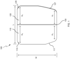
- the rigid wrist shield 100 comprises a first rigid section 110, a second rigid section 120 and a hinge or hinge line 130 wherein the first 110 and second 120 rigid sections are joined via or along the hinge or hinge line 130.
- the rigid wrist shield 100 has a length, L, and a width, W.
- the first rigid section 110 and second rigid section 120 are joined along or via hinge 130 along the length L of the rigid wrist shield 100.
- the first rigid section 110 and second rigid section 120 are preferably made of a rigid plastic material for example Nylon 12 or a chopped composite fibre material. This enables easy manufacture of the rigid wrist shield 100 while ensuring the wrist shield 100 is comfortable for use by the user. Nylon 12 is also believed to be non-irritating to the skin ensuring the wrist shield 100 does not irritate the user during long use.
- the first rigid section 110 and second rigid section 120 can be thin to ensure the wrist shield 100 does not interfere with the activities of the user.
- the first 110 and second 120 rigid sections may have a thickness between 1mm and 5mm such as around 2mm, 3mm, or 4mm although other suitable thicknesses of material can also be used.
- the rigid wrist shield 100 is manufacture using an additive manufacture process enabling the rigid wrist shield 100 to be produced quickly and in different sizes.
- the rigid wrist shield 100 is manufactured in multiple sizes corresponding to the size of gloves, for example, small, medium, large and extra-large.
- Figures 2 , 3A and 3B show the rigid wrist shield 100 positioned on a user's hand 200 and/or the upper part of a user's wrist and thus shows the rigid wrist shield 100 in use.
- the rigid wrist shield 100 may be affixed to the user's hand 200 or wrist in multiple different ways. However for clarity, no additional attachment means are shown in Figures 3A and 3B .
- the first rigid section 110 sits below the second rigid section 120 with the length L of the rigid wrist shield 100 running up the user's hand 200 and the width W of the rigid wrist shield 100 running across the user's hand 200.
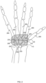
- the first rigid section 110 sits over a portion of the carpal bones 250 of the user's hand 200.
- the second rigid section 120 sits over at least a base portion of the metacarpal bones 260 of the user's hand 200.
- the first rigid section 110 does not sit over the entirety of the carpal bones 250 of the user's hand and the second rigid section 120 sits over a portion of the carpal bones 250 of the user's hand that is not covered by the first rigid section 110.
- the hinge 130 sits over the carpal ligament of the user's hand 200. The positioning of the first rigid section 110 and second rigid section 120 ensures the wrist shield 100 transfers pressure/forces on the user's hand 200 and spreads them across the bones of the user's hand 200. This prevents excess pressure being applied to the carpal area of the user's hand 200 and thus reduces discomfort for the user when the user is applying pressure to an object with their hand 200 in tension or flexion.
- Figures 3A and 3B illustrate the dimensions of the rigid wrist shield 100 relative to the user's hand 200.
- Figure 3A shows how a length L of the rigid wrist shield 100 extends from close to/on the distal wrist crease 215 of the user to a line 220 extending across the hand 200 from the metacarpophalangeal joint of the user's thumb.
- This length L ensures that a user still has full flexibility to bend their wrist and put their wrist in extension or flexion and also ensures the user has full flexibility to move their hand around their knuckle joints (e.g. flex their knuckle joints) without the rigid material of the rigid wrist shield 100 impacting movement.
- this length L increases the area over which any force or pressure on the user's wrist is distributed so decreases discomfort for the user. This length L thus contributes to the ergonomic design of the rigid wrist shield 100.
- Figure 3A also shows how the width W of the rigid wrist shield 100 is shorter than the length of the length of the user's wrist at the distal wrist crease of the user's wrist. This enables the wrist shield 100 to sit comfortably in the palm of the user's hand and/or over the upper wrist of the user. This also ensures the rigid wrist shield 100 does not impede movement of the user's thumb 240.
- the rigid wrist shield 100 is therefore ergonomically designed.
- the width w of rigid wrist shield 100 may be around 90% of the length of the width of the user's wrist at the distal wrist crease. This distributes any pressure/forces on the user's hand/wrist 200 over a large area and increases comfort to the user.
- the width W of the rigid wrist shield 100 may be around 80% or 70% of the length of the user's wrist at the distal wrist crease.
- the width W of the rigid wrist shield 100 may therefore be between 70% and 90% of the length of the user's wrist at the distal wrist crease, between 80% and 90% of the length of the user's wrist at the distal wrist crease, or between 70% and 80% of the length of the user's wrist at the distal wrist crease.
- the width W may be as long as but not longer than the user's wrist at the distal wrist crease.
- Figure 3B shows the rigid wrist shield 100 on a hand/wrist 200 of a user from a side view.
- This Figure show how the hinge 130 enables the wrist shield 100 to sit comfortably against the hand 200 of the user.
- the first rigid section 110 and the second rigid section 120 can pivot along the hinge 130 to ensure the rigid wrist shield 100 sits close to the hand/wrist 200 of the user.
- Figure 3B also shows how the user's movement is not impeded by the presence of the rigid wrist shield 100 due to the positioning of the rigid wrist shield 100 on the user's hand/wrist 200.
- FIG 3A it is possible to see that in use the rigid wrist shield 100 sits on the upper parts of the user's wrist which corresponds to the lower part of the user's hand 200.
- the rigid wrist shield 100 spans the carpal bones 250 of the user's hand and a least a base portion of the metacarpal bones 260. In terms of height, the rigid wrist shield 100 extends from close to the distal wrist crease 215 of the user to a line 220 extending across the hand 200 from the metacarpophalangeal joint of the user's thumb. This prevents the rigid wrist shield 100 impacting movement along the knuckle joints of the user and also enables the user to place their wrist in extension and flexion. In terms of width, the rigid wrist shield 100 is roughly centred along the width of the user's hand.
- the rigid wrist shield 100 has a width W less than (or in other examples at least not more than) the length of user's wrist at the distal wrist crease and is roughly central to the width of the user's hand/wrist 200, means the rigid wrist shield 100 does not prevent movement of the user's thumb 240 when wearing the rigid wrist shield 100.
- the rigid wrist shield 100 is therefore ergonomically designed.
- Figures 4A and 4B show examples of a rigid wrist shield 100 such as the rigid wrist shield 100 described above.
- Figures 4A and 4B show the hinge 130 of the rigid wrist shield 100.
- Figure 4A shows the hinge 130 is in an open position so that the first rigid section 110 and the second rigid section 120 sit substantially parallel to each other.
- Figure 4B shows the hinge 130 in a hinged position wherein the first rigid section 110 and the second rigid section 120 have been tilted towards each other along the hinge line 130.
- the face of the rigid wrist shield 100 shown in Figures 4A and 4B is a face of the rigid wrist shield 100 that will face away from the hand 200 of the user.
- Various forms of hinge 130 may be used.
- a flexible aramid or Kevlar hinge is used.
- the hinge 130 may be a carbon Kevlar hinge or other similar form of hinge. These hinges are light, strong and thin meaning they can be used with the rigid wrist shield 100 without increasing the width of the rigid wrist shield 100.
- hinges of this form are flexible rather than pinching to a tight corner. This means the hinge 130 is not going to pinch or hurt the user when the hinge is placed against the user's hand 200 directly next to the skin.
- the hinge 130 may be a living hinge.
- a living hinge can also be called an integral hinge.
- This form of hinge is made of the same material as the object being hinged wherein the material is thinned along the line of the hinge to allow the material to bend along the hinge line.
- the material formimg the first 110 and second 120 rigid sections is thinned along a joining line to form hinge 130.
- This enables to hinge 130 to be formed easily and integral with the rigid wrist shield 100.
- the hinge 130 can be a reverse action hinge. In other words, as shown in Figure 4B the thinned material is taken from (or never formed in) the surface of the rigid wrist shield 100 that faces away from the user's hand 200.
- the first 110 and second 120 rigid sections are configured to bend/hinge or otherwise move towards each other in direction away from the missing material and towards the hand of the user 200.
- the first 110 and second rigid section 120 pivot towards each other by moving towards a face of the rigid wrist shield 100 opposite to the face along which the material is thinned. This ensures the hinge 130 does not pinch the user when the user has the rigid wrist shield 100 next to their skin. Thus, this increases comfort for the user using the rigid wrist shield 100.
- the wrist shield 100 is approximately rectangular with adjustments for ease of use and comfort e.g. to increase the ergonomic design of the rigid wrist shield 100.
- the corners of the rectangle are rounded to ensure the user does not injure themselves on any sharp corners of the wrist shield 100.
- the second rigid section 120 can be considered an upper section since, as discussed above, it sits above the first rigid section 110 when the rigid wrist shield 100 is in use.
- the second rigid section 120 is approximately rectangular.
- the upper corners of the second rigid section 120 can be defined as the corners not along hinge line 130.
- the lower corners of the second rigid section 120 are those along hinge line 130.
- a first upper corner 125 is rounded. As shown in Figures 3A and 3B in use this first upper corner 125 sits closest to the user's thumb 240.
- a second upper corner 127 of the second rigid section 120 is cut off. In more detail, the second upper corner 127 is replaced by a slopping line that forms a fifth side to the second rigid section 120.
- the second rigid section 120 can thus be considered an irregular pentagon.
- the slope of the line is gentle to avoid overly reducing the size of the second rigid section 120.
- the cut off corner 127 is cut off such that a height H1 of the second rigid section on the side of the cut off corner 127 is around 80% of the height H2 of the second rigid section on the side of the rounded corner 125.
- the heights H1 and H2 are along the same dimension as the length L of the wrist shield 100.
- the height H1 is around 70%, 75%, 85% or around 90% of the height H2.
- the height H1 can therefore be between 70% and 90% of the height H2.
- the cut off corner can be cut off along a substantial portion of the top edge of the second rigid section 120 wherein the top edge of the second rigid section 120 is along the width W of the rigid wrist shield 100.
- the substantial portion can be approximately 45% of the top edge of the second rigid section 120 i.e. 45% of the width w.
- the substantial portion can be 40% or 50% of the top edge of the second rigid section i.e. 40% or 50% of the width W.
- the substantial portion can be between 40% and 50% of the top edge of the second rigid section.
- This sloping corner 127 that, in use, is positioned on the far side of the hand 200 from the user's thumb 240, enables the user to bend their hand along the knuckle joints without this movement being disrupted by the wrist shield 100. This gives the user full flexibility of movement when using the rigid wrist shield 100.
- the first rigid section 110 can be considered a lower rigid section since it sits below the second rigid section 120 when the rigid wrist shield 100 is in use.
- the first rigid section 110 is approximate rectangular.
- the lower corners of the first rigid section 110 are those not along hinge 130.
- the upper corners of the first rigid section 110 are those along hinge 130.
- the lower corners of the first rigid section 110 are rounded. In some examples, this is the only shape adjustment to the first rigid section 110.
- the first rigid section 110 can be the same shape as the second rigid section 120 with one rounded corner and one cut off corner wherein a side of the first rigid section with the cut off corner has a height roughly 70% to 90% of the height of the side of the first rigid section with the rounded corner.
- the cut off corner can meet the bottom edge of the first rigid section at a point around 40% and 50% along the width of the wrist shield 100. As shown in Figure 4B the cut off corner of the first rigid section 110 is directly below the cut off corner 127 of the second rigid section 120.
- the first rigid section 110 of the rigid wrist shield 100 comprises a rounded corner 115 and a cut off corner 117 although the cut off corner 117 is not cut off to the same degree as cut off corner 127 of the second rigid section 120.
- a height K1 of the edge of the first rigid section 110 with the cut off corner 117 is around 85% of the height K2 of the edge of the first rigid section 110 with rounded corner 115.
- the heights K1 and K2 are along the length L of the wrist shield 100.
- K1 may be between 70% and 90% of K2 and for example may be 70% of K2, 75% of K2, 80% of K2 or 90% of K2.
- the cut off corner 117 meets the bottom edge of the first rigid section 110 at a point along around 30% of the width of the bottom edge wherein the width of the bottom edge is the width W of the wrist shield 100. In other examples, the cut off corner 117 meets the bottom edge of the first rigid section 110 at a point along between 20% and 40% of the width of the bottom edge, for example at 20%, 25%, 35% or 40% of the width of the bottom edge. As shown in Figure 1 , the cut off corner 117 is directly below the cut off corner 127. The cut off corner 117 can prevent the wrist shield 100 extending beyond the user's hand 200 when the user's wrist is in extension or flexion.
- the first 110 and second 120 rigid sections of the rigid wrist shield 100 are therefore sized and shaped to spread force/pressure across the user's wrist while not impeding movement of the user's hand/wrist.
- the rigid wrist shield 100 is therefore ergonomically designed.
- rigid wrist shield 100 can function as a tool to aid in vehicle manufacture such as aircraft manufacture for example during carbon fibre layup.
- rigid wrist shield 100 comprises a first rigid section 110 and a second rigid section 120 connected together via a hinge 130.
- first 110 and second 120 rigid sections sit substantially parallel to each other such that the rigid wrist shield 100 is not bent along hinge 130.
- the first 110 and second 120 rigid sections can pivot towards each other along/via hinge 130.
- the first 110 and second 120 rigid sections pivot towards each other and towards rather than away from the palm of the user's hand 200. This ensures the rigid wrist shield 100 continues to provide shield when the user's wrist/hand is in flexion or extension. This also maintains the comfort of the rigid wrist shield 100 and enables a user to fully move their wrist.
- Figure 5 shows the rigid wrist shield 100 also be used as a tool when the user has their wrist/hand in extension.
- the user has their wrist in an angle of extension of around 70° to 90°.
- the angle of extension can be taken to be an angle between the arm and the palm of the user's hand.
- the angle between the first rigid section 110 and the second rigid section 120 of the rigid wrist shield 100 is around 90°.
- this enables the user to apply a pressure to a surface via first rigid section 110.
- the hinge 130 can be used as a scraper which can be used for hand lay of carbon fibre materials.
- Figure 5 shows a 90° angle between the first 110 and second 120 rigid sections
- a user could use the first rigid section 110, the second rigid section 120 or both to apply pressure to hand layup at other angels including in a neutral position where the first 110 and second 120 rigid sections are parallel.
- the hinge 130 could be used as scrapper at multiple angles between the first 110 and second 120 rigid section dependent upon the task for which the scraper is used and what is comfortable for the user.
- a hinge 130 is used as a tool
- a roller could be used in place of the hinge which could enable both pivoting between the first 110 and second 120 rigid sections and the functioning of the wrist shield 100 as a roller tool.
- a roller may be present on either the first 110 or second 120 rigid section so that the rigid wrist shield 100 can also be used as a roller tool.
- the rigid wrist shield 100 described above can be used in combination with a glove 400.
- the glove 400 may be a felt glove that acts as personal protective equipment for carbon fibre material.
- the wrist shield 100 can be used with other gloves in other contexts.
- the rigid wrist shield 100 may be produced in a selection of sizes in line with the sizes of gloves available.
- the rigid wrist shield 100 may be available in sizes small, medium, large and extra-large. This ensures the rigid wrist shield 100 is available in a range of sizes that will suit and be comfortable for most users.
- the rigid wrist shield 100 can be mounted on the glove.
- the rigid wrist 100 can be sewn or stuck onto the outside of glove 400 or attached to glove 400 in any other suitable way.
- the rigid wrist shield 100 can also be placed in glove 400.
- the user can place the rigid wrist shield 100 on their hand/wrist in the correct position and the glove 400 can be placed over the hand. The glove 400 can then hold the wrist shield 100 in place due to the closeness of the glove 400 and the user's hand.
- the rigid wrist shield 100 can be sewn, glued or otherwise mounted into the glove 400 in the correct position. When the user puts the glove 400 on the rigid wrist shield 100 can then be in the correct position compared to their hand/wrist to spread force/pressure across their wrist.
- the rigid wrist shield 100 can also be used with a padding support 210.
- the padding support 210 comprises a flexible mesh that sits over a palm of the user and provides padding to protect the palm of the user and provide comfort to the user.
- the padding support 210 can also reduce/remove vibration when the rigid wrist shield 100 is used while handling a vibrating object such as an ultrasonic knife.
- the mesh can be a mesh of cut aways separated by thin sections of the padding support. This enables the padding support to be stretched to fit different sized hands.
- the cut aways are hexagonal cut aways although other shaped cut aways may be used.
- the padding support 210 may comprise a thumb strap that sits over the top of the thumb 240 and holds the padding support 210 in place.
- a second support strap may sit between the thumb 240 and the index finger 270 and further hold the padding support 210 in place.
- a third strap may span the back of the hand and hold the padding support 210 in place without providing padding to the back of the hand 200.
- the padding support 210 may extend over the entire width of the hand 210 and may extend from the distal wrist crease to a lower end of the proximal palmar crease. The padding support 210 therefore can roughly cover a third to a half of the user's palm. This padding support 210 provides additional protection for the user.
- the padding support 210 may be made of a plastic material such as a soft plastic material for example a clear soft plastic material.
- the rigid wrist shield 100 can be sit beneath the padding support 210 and be held in place by the padding support 210. To this end, the user can position the rigid wrist shield 100 on their hand and then put on the padding support 210 thus holding the rigid wrist shield 100 in place.
- the rigid wrist shield 100 can be attached to the inside of the padding support 210 and when the user puts on the padding support 210 the rigid wrist shield 100 can be correctly positioned with respect to the user's hand. To this end the wrist shield 100 can be glued, sewn or otherwise mounted to the padding support 210.
- the rigid wrist shield 100 can be attached to the outside of the padding support 210. In use, the padding support 210 therefore sits between the user's hand 200 and the rigid wrist shield 100. To this end, the rigid wrist shield 100 can be glued, sewn or otherwise mounted to the padding support 210. When the user puts on the padding support 210 the rigid wrist shield 100 is then correctly positioned with respect to the user's hand 200.
- the padding/flexible mesh on the padding support 210 can be cut away or otherwise removed from an area 230 of the padding support 210 above/beneath the rigid wrist shield 100.
- This can be known as a cut away, hole, gap, or opening 230.
- the flexible mesh of the padding support 210 can be cut away such that in use, the cut away/hole/gap/opening 230 sits over the carpal tunnel area of the user's wrist.
- the cut away 230 in the padding support 210 can sit over the carpal tunnel area of the user's wrist.
- the cut away 230 can be on an area over the user's carpal bones or between the user's carpal and metacarpal bones and roughly central to the width of the user's hand at this area. This prevents the padding support 210 applying undue pressure or force to a small area of the user's wrist and thus causing discomfort for the user.
- the cut away can have a width, in use, that is around half (e.g. 50%) the width of the user's hand at this area. To this end the cut away can have a width, in use, that is between 40% and 60% of the width of the user's hand at the position of the cut away.
- the bottom of the padding support 210 can be considered to be the part of the padding support 210 that sits lowest on the hand 200 e.g. the part that sits furthest from the user's thumb 240 and fingers.
- the cut away 230 on the padding support 210 may extend from a quarter (25%) of the distance between the bottom and top of the padding support to a half (50%) of the distance between the bottom and top of the padding support when taken from the bottom edge. In other examples, this may be from 15% to 25% of the distance between the bottom and top to 40% to 60% of the distance between the bottom and top when taken from the bottom edge.
- the cut away 230 can extend from around 30% to 60% of a width of the padding support 210.
- the cut away 230 can extend from around 30% to 60% of the width of the padding support 210 when starting from an end of the padding support 210 that sits furthest from the user's thumb 240.
- the width of the cut away 230 can be between 20% to 40% and 50% to 70% of the width of the padding support 210.
- this cut away 230 is used when the rigid wrist shield 100 sits above the padding support 210 as this prevents the rigid wrist shield 100 applying pressure to a small area of the user's wrist through the padding support 210.
- the cut away 230 can be used when the rigid wrist shield 100 sits beneath the padding support 210.
- the rigid wrist shield 100 and padding support 210 can be used with or without glove 400 which may be a felt glove used for personal protective equipment during carbon fibre layup for vehicle/aircraft manufacture or other similar processes.
- the user attaches the rigid wrist shield 100 to their hand/wrist 100 such that the first rigid section 110 sits over a portion of the carpal bone's 250 of the user's hand and the second rigid section 120 sits over at least a base portion of the metacarpal bones 260 of the user's hand.
- This ensures the rigid wrist shield 100 is correctly positioned to spread force and/or pressure over the upper portion of the user's wrist.
- the second rigid section 120 may also sit over a portion of the user's carpal bone's 250 not covered by the first rigid section 110.
- the hinge 130 of the rigid wrist shield 100 When in use the hinge 130 of the rigid wrist shield 100 enables the first rigid section 110 and second rigid section 120 to pivot with respect to each other. When the user's wrist is in a neutral position then the first rigid section 110 and second rigid section 120 can sit roughly parallel to each other as shown in Figures 3A and 3B . However, as shown in Figure 5 when the user's hand/wrist is in extension then the first rigid section 110 and second rigid section 120 can pivot towards each other and towards the user wrist/hand along the hinge line 130. This ensures the user has flexibility to move their wrist and also enables the rigid wrist shield 100 to be used as a tool for carbon fibre layup, as described above.
- the rigid wrist shield 100 can be attached to the user's wrist/hand in multiple ways.
- the rigid wrist shield 100 can be attached to a glove 400 either inside or outside the glove 400. Attaching the wrist shield 100 to the user's wrist/hand can therefore be performed by the user putting on the glove 400.
- the rigid wrist shield 100 can be attached to a padding support 210. Attaching the wrist shield 100 to the user's wrist/hand can therefore be performed by the user putting on the padding support 210.
- both a padding support 210 and a glove 400 can be used and all three components can be attached together.
- the rigid wrist shield 100 can be on the outside of the glove 400, between the glove 400 and the padding support 210 or inside the padding support 210.
- the rigid wrist shield 100 can be aligned with the user's hand 200. The user can then put on a glove 400 or padding support 210 to hold the rigid wrist shield 100 in place. Other ways of attaching the rigid wrist shield 100 to the user's hand/wrist can also be used as appropriate.
- a rigid wrist shield 100 is defined.
- the rigid wrist shield 100 is an ergonomically designed device that can be stitched into a standard felt glove 400 or otherwise provided with or separate from a glove 400.
- the device spreads force/pressure over the upper wrist/lower palm section of a user's hand and thus reduces discomfort.
- the rigid wrist shield bridges over the tendons and median nerve in the user's wrist and spreads force/pressure onto the carpal bone at either side.
- the rigid wrist shield can thus reduce force/pressure on sensitive areas of the user's wrist.
- a range of materials can be used for the rigid wrist shield 100 although some examples are manufactured from Nylon 12 using the additive manufacturing process.
- the ergonomic design of the rigid wrist shield 100 ensures the rigid wrist shield 100 does not cause discomfort to the user and also ensures the rigid wrist shield 100 does not impede movement of the user's hand and wrist.
- the rigid wrist shield 100 is an ergonomically shaped insert into the layup personal protective equipment (e.g. a felt glove) which serves the purpose of providing protection over the upper area of the user's wrist. Due to the nature of the designed insert an additional benefit is also provided to the operator in the form of a smooth hard surface or tool that aids the operator perform an operation during aircraft manufacture.
Landscapes
- Engineering & Computer Science (AREA)
- Textile Engineering (AREA)
- Health & Medical Sciences (AREA)
- General Health & Medical Sciences (AREA)
- Physical Education & Sports Medicine (AREA)
- Professional, Industrial, Or Sporting Protective Garments (AREA)
Abstract
A rigid wrist shield for spreading force and/or pressure across a palmer side of a wrist of a hand of a user. The rigid wrist shield comprises a first rigid section wherein, in use, the first rigid section sits over a portion of the carpal bones of the user's hand. The rigid wrist shield further comprises a second rigid section wherein, in use, the second region section sits over at least a base portion of the metacarpal bones of the user's hand. The rigid wrist shield also comprises a hinge joining the first rigid section to the second rigid section.
Description
- The present invention relates to a rigid wrist shield that is configured to sit over an upper part of a user's wrist and/or a lower part of a user's hand and to spread forces and/or pressure across the user's wrist/hand.
- Currently, during the hand layup of carbon fibre products, operators wear standard PPE (personal protective equipment) felt gloves in order to lay down material. During this process pressure is applied by the operator using the wrist area of the hand, this can cause discomfort for the worker due to the constant repetitive nature of the process. It would be desirable to provide a shield that can be used with felt gloves to spread force and or pressure across the user's wrist/hand to prevent excess force and/or pressure being applied to a single area of the wrist/hand and hence to reduce discomfort during the hand layup process. It is noted that such a wrist shield may also have other functions outside of hand layup and may be used separately or with other gloves than felt gloves.
- According to an aspect of the present invention, there is provided a rigid wrist shield for spreading force and/or pressure across a palmer side of a wrist of a hand of a user. The rigid wrist shield comprises a first rigid section wherein, in use, the first rigid section sits over a portion of the carpal bones of the user's hand. The rigid wrist shield also comprises a second rigid section wherein, in use, the second region section sits over at least a base portion of the metacarpal bones of the user's hand. The rigid wrist shield further comprises a hinge joining the first rigid section to the second rigid section. The skilled person would understand that in some examples the wrist shield can also be called a hand shield, a wrist support or a hand support.
- In some examples, when, in use, the hinge of the rigid wrist shield sits over the carpal ligament of the user's hand.
- In some examples, a width of the rigid wrist shield is shorter than a length of the user's wrist at the distal wrist crease of the user. The first rigid section and the second rigid section can be joined along a length of the rigid wrist shield. The length of the rigid wrist shield can correspond to a length from the distal wrist crease of the user to a line extended from the metacarpophalangeal joint of the user's thumb.
- In some examples, the width of the rigid wrist shield is between 70% and 90% of the length of the user's wrist at the distal wrist crease of the user.
- In some examples, the second rigid section is an irregular pentagon comprising a rectangle with rounded corners wherein a first upper corner of the second rigid section is cut off in that the first upper corner of the rectangle has been replaced by an additional side that slopes gently from a first side of the rectangle to a top side of the rectangle. In this example, in some instances, a height of the first side of the second rigid section with the additional side may be between 70% and 90% of a height of a second side of the second rigid section opposite the additional side. In these instances the additional side may meet the top side of the second rigid section at a point along between 40% and 50% of a width of the top side.
- In some examples, the first rigid section is a rectangle with rounded corners. In other examples, the first rigid section is an irregular pentagon comprising a rectangle with rounded corners wherein a first lower corner of the first rigid section is cut off in that the first lower corner of the rectangle has been replaced by an additional side that slopes gently from a first side of the rectangle to a bottom side of the rectangle. When the first rigid section is an irregular pentagon, in some instances, a height of the first side of the first rigid section with the additional side may be between 80% and 90% of a height of a second side of the first rigid section opposite the additional side. In these instances, the additional side may meet the bottom side of the first rigid section at a point along between 20% and 40% of a width of the bottom side.
- In some examples, the hinge comprises a flexible aramid or Kevlar hinge. In other examples, the hinge comprises a reverse action living hinge.
- In some examples, the first rigid section and the section region section comprise a hard plastic. In this example, the hard plastic may, in some instances, be either Nylon 12 or a chopped fibre material.
- According to an aspect of the present invention, there is provided a glove for use in vehicle manufacture, the glove comprising a glove and a rigid wrist shield such as the rigid wrist shield described above. The rigid wrist shield can be mounted in or on the glove. The skilled person would understand that the glove can also be referred to as an item of personal protective equipment, a glove apparatus, or adapted glove to distinguish the glove with the rigid wrist shield from the glove without the rigid wrist shield.
- In some examples, the glove/adapted glove further comprises a padding support wherein the padding support comprises a flexible mesh that, in use, covers a lower section of the palm of the user's hand. The rigid wrist shield can be positioned beneath or above the padding support.
- In some examples where the rigid wrist shield is positioned above the padding support, a section of the flexible mesh of the padding support beneath the rigid wrist shield has been removed.
- In some examples, the glove (e.g. the glove that forms part of the adapted glove) is a felt glove.
- According to an aspect of the present invention, there is provided a method of using a rigid wrist shield or glove such as those described above. The method comprises attaching the rigid wrist shield to the hand of the user such that the first rigid section sits over a portion of the carpal bones of the user's hand and the second rigid section sits over at least a base portion of the metacarpal bones of the user's hand.
- In some examples when the user's wrist is in a neutral position the first rigid section and the second rigid section sit substantially parallel to each other and when the user's wrist is in extension, the first rigid section and second rigid section hinge towards each other and toward the user's wrist along the hinge.
- In some examples, the method further comprises using the rigid wrist shield as a scraper to aid in carbon fibre layup when the user's wrist is in extension.
- In some examples, the method further comprises using the first rigid section and/or the second rigid section of the rigid wrist shield to apply pressure to a surface during carbon fibre layup.
- In some examples, attaching the rigid wrist shield to the hand of the user comprises positioning the rigid wrist shield on the hand of the user and holding the rigid wrist shield in place using a padding support or glove. In other examples, the rigid wrist shield is attached to a glove; and attaching the rigid wrist shield to the hand of the user comprises the user putting on the glove. In further examples, the rigid wrist shield is attached to a padding support; and attaching the rigid wrist shield to the hand of the user comprises the user putting on the padding support. In yet further examples, the rigid wrist shield is attached to a padding support; the padding support is attached to a glove; and attaching the rigid wrist shield to the hand of the user comprises the user putting on the glove.
- Embodiments of the invention will now be described by way of example only with reference to the figures, in which:
-
Figure 1 shows a rigid wrist shield in accordance with an example of the disclosure; -
Figure 2 shows a rigid wrist shield aligned with the bones of a user's hand to show how the rigid wrist shield sits on a user's hand; -
Figure 3A shows a front view of rigid wrist shield aligned with a user's wrist/hand; -
Figure 3B shows a side view of a rigid wrist shield aligned with a user's wrist/hand; -
Figure 4A shows a rigid wrist shield with the hinge in a first open position; -
Figure 4B shows a rigid wrist shield with the hinge in a second hinged position; -
Figure 5 shows a user using the rigid wrist shield as a tool for carbon fibre layup; -
Figure 6A shows the use of a rigid wrist shield on the outside of a glove; -
Figure 6B shows the use of a rigid wrist shield on the inside of a glove; -
Figure 6C shows the use of a rigid wrist shield with a padding support; and -
Figure 7 shows a padding support that can be used with a rigid wrist shield wherein the padding support has a cut away. - The application relates to a rigid wrist shield that is configured to sit over an upper part of a user's wrist and/or a lower part of a user's hand and to spread forces and/or pressure across the user's wrist/hand, for example during vehicle or aircraft manufacture. This prevents an excess force and/or pressure being applied to a single section of the user's wrist which could result in discomfort for the user.
- A rigid wrist shield is described. The rigid wrist shield is configured to sit over an upper part of the wrist of a user on the palmer/front side wherein the upper part of the wrist can be considered to run from just above a distal wrist crease of the user to a base portion of the metacarpal bones of the user. The rigid wrist shield can spread force and/or pressure across a front/palmer side of the wrist/hand. That is the rigid wrist shield can spread force/pressure over the front of the user's wrist/hand e.g. over the palm side of the user's wrist/hand. This prevents undue force/pressure being applied to a small area on the front/palmer side of the user's wrist/hand.
- While the rigid wrist shield is described as being a wrist shield, in other examples the rigid wrist shield could be considered to be a rigid hand shield or a rigid carpal shield. In other examples the rigid wrist shield can be described as a rigid wrist support, a rigid hand support or a rigid carpal support. The wrist shield is rigid in that the wrist shield is made from a hard, solid or otherwise inflexible material. The wrist shield can thus be thought of as rigid since it can be considered inflexible, nonflexible, impliable, unbending or stiff e.g. it is not flexible or pliable. In some examples, the wrist shield is considered rigid because it does not bend or yield in use other than along a hinge in the wrist shield.
- During vehicle and aircraft manufacture and other similar tasks, a user may be required to put pressure on the upper part of their wrist due to the need for their wrist to be in extension or flexion. For example when hand laying up carbon fibre products, a user may be required to apply pressure to the carbon fibre product using their hand whilst their wrist is in extension. The rigid wrist shield described herein sits over the upper part of the user's wrist on the palm/front side and spreads the pressure placed on the wrist when the wrist is in extension and flexion so that the pressure is spread around the carpal and metacarpal bones of the user's hand/wrist. This reduces the pressure placed on a single area of the user's hand/wrist and thus can reduce discomfort for the user.
- An example
rigid wrist shield 100 is shown inFigure 1 . The rigid wrist shield comprises a firstrigid section 110, a secondrigid section 120 and a hinge or hingeline 130 wherein the first 110 and second 120 rigid sections are joined via or along the hinge or hingeline 130. As shown inFigure 1 , therigid wrist shield 100 has a length, L, and a width, W. The firstrigid section 110 and secondrigid section 120 are joined along or viahinge 130 along the length L of therigid wrist shield 100. - The first
rigid section 110 and secondrigid section 120 are preferably made of a rigid plastic material for example Nylon 12 or a chopped composite fibre material. This enables easy manufacture of therigid wrist shield 100 while ensuring thewrist shield 100 is comfortable for use by the user. Nylon 12 is also believed to be non-irritating to the skin ensuring thewrist shield 100 does not irritate the user during long use. The firstrigid section 110 and secondrigid section 120 can be thin to ensure thewrist shield 100 does not interfere with the activities of the user. In some examples the first 110 and second 120 rigid sections may have a thickness between 1mm and 5mm such as around 2mm, 3mm, or 4mm although other suitable thicknesses of material can also be used. In some examples therigid wrist shield 100 is manufacture using an additive manufacture process enabling therigid wrist shield 100 to be produced quickly and in different sizes. In some examples therigid wrist shield 100 is manufactured in multiple sizes corresponding to the size of gloves, for example, small, medium, large and extra-large. -
Figures 2 ,3A and 3B show therigid wrist shield 100 positioned on a user'shand 200 and/or the upper part of a user's wrist and thus shows therigid wrist shield 100 in use. As discussed later, therigid wrist shield 100 may be affixed to the user'shand 200 or wrist in multiple different ways. However for clarity, no additional attachment means are shown inFigures 3A and 3B . When in use, the firstrigid section 110 sits below the secondrigid section 120 with the length L of therigid wrist shield 100 running up the user'shand 200 and the width W of therigid wrist shield 100 running across the user'shand 200. As shown inFigure 2 the firstrigid section 110 sits over a portion of thecarpal bones 250 of the user'shand 200. The secondrigid section 120 sits over at least a base portion of themetacarpal bones 260 of the user'shand 200. In some examples, the firstrigid section 110 does not sit over the entirety of thecarpal bones 250 of the user's hand and the secondrigid section 120 sits over a portion of thecarpal bones 250 of the user's hand that is not covered by the firstrigid section 110. Thehinge 130 sits over the carpal ligament of the user'shand 200. The positioning of the firstrigid section 110 and secondrigid section 120 ensures thewrist shield 100 transfers pressure/forces on the user'shand 200 and spreads them across the bones of the user'shand 200. This prevents excess pressure being applied to the carpal area of the user'shand 200 and thus reduces discomfort for the user when the user is applying pressure to an object with theirhand 200 in tension or flexion. -
Figures 3A and 3B illustrate the dimensions of therigid wrist shield 100 relative to the user'shand 200.Figure 3A shows how a length L of therigid wrist shield 100 extends from close to/on thedistal wrist crease 215 of the user to aline 220 extending across thehand 200 from the metacarpophalangeal joint of the user's thumb. This length L ensures that a user still has full flexibility to bend their wrist and put their wrist in extension or flexion and also ensures the user has full flexibility to move their hand around their knuckle joints (e.g. flex their knuckle joints) without the rigid material of therigid wrist shield 100 impacting movement. In addition, this length L increases the area over which any force or pressure on the user's wrist is distributed so decreases discomfort for the user. This length L thus contributes to the ergonomic design of therigid wrist shield 100. -
Figure 3A also shows how the width W of therigid wrist shield 100 is shorter than the length of the length of the user's wrist at the distal wrist crease of the user's wrist. This enables thewrist shield 100 to sit comfortably in the palm of the user's hand and/or over the upper wrist of the user. This also ensures therigid wrist shield 100 does not impede movement of the user'sthumb 240. Therigid wrist shield 100 is therefore ergonomically designed. The width w ofrigid wrist shield 100 may be around 90% of the length of the width of the user's wrist at the distal wrist crease. This distributes any pressure/forces on the user's hand/wrist 200 over a large area and increases comfort to the user. In other examples, the width W of therigid wrist shield 100 may be around 80% or 70% of the length of the user's wrist at the distal wrist crease. The width W of therigid wrist shield 100 may therefore be between 70% and 90% of the length of the user's wrist at the distal wrist crease, between 80% and 90% of the length of the user's wrist at the distal wrist crease, or between 70% and 80% of the length of the user's wrist at the distal wrist crease. In other examples, the width W may be as long as but not longer than the user's wrist at the distal wrist crease. -
Figure 3B shows therigid wrist shield 100 on a hand/wrist 200 of a user from a side view. This Figure show how thehinge 130 enables thewrist shield 100 to sit comfortably against thehand 200 of the user. As shown inFigure 3B the firstrigid section 110 and the secondrigid section 120 can pivot along thehinge 130 to ensure therigid wrist shield 100 sits close to the hand/wrist 200 of the user.Figure 3B also shows how the user's movement is not impeded by the presence of therigid wrist shield 100 due to the positioning of therigid wrist shield 100 on the user's hand/wrist 200. Referring toFigure 3A it is possible to see that in use therigid wrist shield 100 sits on the upper parts of the user's wrist which corresponds to the lower part of the user'shand 200. As described above, therigid wrist shield 100 spans thecarpal bones 250 of the user's hand and a least a base portion of themetacarpal bones 260. In terms of height, therigid wrist shield 100 extends from close to thedistal wrist crease 215 of the user to aline 220 extending across thehand 200 from the metacarpophalangeal joint of the user's thumb. This prevents therigid wrist shield 100 impacting movement along the knuckle joints of the user and also enables the user to place their wrist in extension and flexion. In terms of width, therigid wrist shield 100 is roughly centred along the width of the user's hand. As shown inFigure 3B , the fact that therigid wrist shield 100 has a width W less than (or in other examples at least not more than) the length of user's wrist at the distal wrist crease and is roughly central to the width of the user's hand/wrist 200, means therigid wrist shield 100 does not prevent movement of the user'sthumb 240 when wearing therigid wrist shield 100. Therigid wrist shield 100 is therefore ergonomically designed. -
Figures 4A and 4B show examples of arigid wrist shield 100 such as therigid wrist shield 100 described above.Figures 4A and 4B show thehinge 130 of therigid wrist shield 100.Figure 4A shows thehinge 130 is in an open position so that the firstrigid section 110 and the secondrigid section 120 sit substantially parallel to each other.Figure 4B shows thehinge 130 in a hinged position wherein the firstrigid section 110 and the secondrigid section 120 have been tilted towards each other along thehinge line 130. The face of therigid wrist shield 100 shown inFigures 4A and 4B is a face of therigid wrist shield 100 that will face away from thehand 200 of the user. Various forms ofhinge 130 may be used. - In some examples a flexible aramid or Kevlar hinge is used. In this regard the
hinge 130 may be a carbon Kevlar hinge or other similar form of hinge. These hinges are light, strong and thin meaning they can be used with therigid wrist shield 100 without increasing the width of therigid wrist shield 100. In addition, hinges of this form are flexible rather than pinching to a tight corner. This means thehinge 130 is not going to pinch or hurt the user when the hinge is placed against the user'shand 200 directly next to the skin. - In other examples, the
hinge 130 may be a living hinge. A living hinge can also be called an integral hinge. This form of hinge is made of the same material as the object being hinged wherein the material is thinned along the line of the hinge to allow the material to bend along the hinge line. When a living hinge is used withrigid wrist shield 100, then the material formimg the first 110 and second 120 rigid sections is thinned along a joining line to formhinge 130. This enables to hinge 130 to be formed easily and integral with therigid wrist shield 100. When a living hinge is used thehinge 130 can be a reverse action hinge. In other words, as shown inFigure 4B the thinned material is taken from (or never formed in) the surface of therigid wrist shield 100 that faces away from the user'shand 200. The first 110 and second 120 rigid sections are configured to bend/hinge or otherwise move towards each other in direction away from the missing material and towards the hand of theuser 200. In other words, the first 110 and secondrigid section 120 pivot towards each other by moving towards a face of therigid wrist shield 100 opposite to the face along which the material is thinned. This ensures thehinge 130 does not pinch the user when the user has therigid wrist shield 100 next to their skin. Thus, this increases comfort for the user using therigid wrist shield 100. - From
Figures 1 and4 it is possible to see the shape of therigid wrist shield 100. Thewrist shield 100 is approximately rectangular with adjustments for ease of use and comfort e.g. to increase the ergonomic design of therigid wrist shield 100. The corners of the rectangle are rounded to ensure the user does not injure themselves on any sharp corners of thewrist shield 100. - The second
rigid section 120 can be considered an upper section since, as discussed above, it sits above the firstrigid section 110 when therigid wrist shield 100 is in use. The secondrigid section 120 is approximately rectangular. The upper corners of the secondrigid section 120 can be defined as the corners not alonghinge line 130. The lower corners of the secondrigid section 120 are those alonghinge line 130. Of the upper corners of the secondrigid section 120, a firstupper corner 125 is rounded. As shown inFigures 3A and 3B in use this firstupper corner 125 sits closest to the user'sthumb 240. A secondupper corner 127 of the secondrigid section 120 is cut off. In more detail, the secondupper corner 127 is replaced by a slopping line that forms a fifth side to the secondrigid section 120. The secondrigid section 120 can thus be considered an irregular pentagon. The slope of the line is gentle to avoid overly reducing the size of the secondrigid section 120. In some examples, the cut offcorner 127 is cut off such that a height H1 of the second rigid section on the side of the cut offcorner 127 is around 80% of the height H2 of the second rigid section on the side of therounded corner 125. The heights H1 and H2 are along the same dimension as the length L of thewrist shield 100. In other examples the height H1 is around 70%, 75%, 85% or around 90% of the height H2. The height H1 can therefore be between 70% and 90% of the height H2. The cut off corner can be cut off along a substantial portion of the top edge of the secondrigid section 120 wherein the top edge of the secondrigid section 120 is along the width W of therigid wrist shield 100. In some examples, the substantial portion can be approximately 45% of the top edge of the secondrigid section 120 i.e. 45% of the width w. In other examples, the substantial portion can be 40% or 50% of the top edge of the second rigid section i.e. 40% or 50% of the width W. The substantial portion can be between 40% and 50% of the top edge of the second rigid section. Thissloping corner 127 that, in use, is positioned on the far side of thehand 200 from the user'sthumb 240, enables the user to bend their hand along the knuckle joints without this movement being disrupted by thewrist shield 100. This gives the user full flexibility of movement when using therigid wrist shield 100. - The first
rigid section 110 can be considered a lower rigid section since it sits below the secondrigid section 120 when therigid wrist shield 100 is in use. The firstrigid section 110 is approximate rectangular. The lower corners of the firstrigid section 110 are those not alonghinge 130. The upper corners of the firstrigid section 110 are those alonghinge 130. The lower corners of the firstrigid section 110 are rounded. In some examples, this is the only shape adjustment to the firstrigid section 110. - In other examples, such as shown in
Figure 4B , the firstrigid section 110 can be the same shape as the secondrigid section 120 with one rounded corner and one cut off corner wherein a side of the first rigid section with the cut off corner has a height roughly 70% to 90% of the height of the side of the first rigid section with the rounded corner. The cut off corner can meet the bottom edge of the first rigid section at a point around 40% and 50% along the width of thewrist shield 100. As shown inFigure 4B the cut off corner of the firstrigid section 110 is directly below the cut offcorner 127 of the secondrigid section 120. - In a further example, shown in
Figures 1 and4A , the firstrigid section 110 of therigid wrist shield 100 comprises arounded corner 115 and a cut offcorner 117 although the cut offcorner 117 is not cut off to the same degree as cut offcorner 127 of the secondrigid section 120. In this example a height K1 of the edge of the firstrigid section 110 with the cut offcorner 117 is around 85% of the height K2 of the edge of the firstrigid section 110 withrounded corner 115. The heights K1 and K2 are along the length L of thewrist shield 100. In other examples, K1 may be between 70% and 90% of K2 and for example may be 70% of K2, 75% of K2, 80% of K2 or 90% of K2. The cut offcorner 117 meets the bottom edge of the firstrigid section 110 at a point along around 30% of the width of the bottom edge wherein the width of the bottom edge is the width W of thewrist shield 100. In other examples, the cut offcorner 117 meets the bottom edge of the firstrigid section 110 at a point along between 20% and 40% of the width of the bottom edge, for example at 20%, 25%, 35% or 40% of the width of the bottom edge. As shown inFigure 1 , the cut offcorner 117 is directly below the cut offcorner 127. The cut offcorner 117 can prevent thewrist shield 100 extending beyond the user'shand 200 when the user's wrist is in extension or flexion. - The first 110 and second 120 rigid sections of the
rigid wrist shield 100 are therefore sized and shaped to spread force/pressure across the user's wrist while not impeding movement of the user's hand/wrist. Therigid wrist shield 100 is therefore ergonomically designed. - As shown in
Figure 5 , as well as acting as a wrist shield,rigid wrist shield 100 can function as a tool to aid in vehicle manufacture such as aircraft manufacture for example during carbon fibre layup. - As discussed above,
rigid wrist shield 100 comprises a firstrigid section 110 and a secondrigid section 120 connected together via ahinge 130. As shown inFigures 3A and 3B , when a user has theirhand 200 in a neutral wrist position the first 110 and second 120 rigid sections sit substantially parallel to each other such that therigid wrist shield 100 is not bent alonghinge 130. When the user bends their wrist and so has their hand/wrist in extension or flexion the first 110 and second 120 rigid sections can pivot towards each other along/viahinge 130. As shown inFigure 5 , the first 110 and second 120 rigid sections pivot towards each other and towards rather than away from the palm of the user'shand 200. This ensures therigid wrist shield 100 continues to provide shield when the user's wrist/hand is in flexion or extension. This also maintains the comfort of therigid wrist shield 100 and enables a user to fully move their wrist. -
Figure 5 shows therigid wrist shield 100 also be used as a tool when the user has their wrist/hand in extension. InFigure 5 , the user has their wrist in an angle of extension of around 70° to 90°. The skilled person would understand that the angle of extension can be taken to be an angle between the arm and the palm of the user's hand. As a result of this extension, the angle between the firstrigid section 110 and the secondrigid section 120 of therigid wrist shield 100 is around 90°. As shown inFigure 5 , this enables the user to apply a pressure to a surface via firstrigid section 110. In addition, thehinge 130 can be used as a scraper which can be used for hand lay of carbon fibre materials. WhileFigure 5 shows a 90° angle between the first 110 and second 120 rigid sections, a user could use the firstrigid section 110, the secondrigid section 120 or both to apply pressure to hand layup at other angels including in a neutral position where the first 110 and second 120 rigid sections are parallel. In addition, thehinge 130 could be used as scrapper at multiple angles between the first 110 and second 120 rigid section dependent upon the task for which the scraper is used and what is comfortable for the user. While inFigure 5 , ahinge 130 is used as a tool, in other examples, a roller could be used in place of the hinge which could enable both pivoting between the first 110 and second 120 rigid sections and the functioning of thewrist shield 100 as a roller tool. In other examples a roller may be present on either the first 110 or second 120 rigid section so that therigid wrist shield 100 can also be used as a roller tool. - The
rigid wrist shield 100 described above can be used in combination with aglove 400. In the context of vehicle and/or aircraft manufacture theglove 400 may be a felt glove that acts as personal protective equipment for carbon fibre material. However, thewrist shield 100 can be used with other gloves in other contexts. As therigid wrist shield 100 can be used with aglove 400, therigid wrist shield 100 may be produced in a selection of sizes in line with the sizes of gloves available. For example, therigid wrist shield 100 may be available in sizes small, medium, large and extra-large. This ensures therigid wrist shield 100 is available in a range of sizes that will suit and be comfortable for most users. - As shown in
Figures 6A when therigid wrist shield 100 is used with aglove 400 then therigid wrist shield 100 can be mounted on the glove. For example, therigid wrist 100 can be sewn or stuck onto the outside ofglove 400 or attached toglove 400 in any other suitable way. In another example, shown inFigure 6B , therigid wrist shield 100 can also be placed inglove 400. In some examples, the user can place therigid wrist shield 100 on their hand/wrist in the correct position and theglove 400 can be placed over the hand. Theglove 400 can then hold thewrist shield 100 in place due to the closeness of theglove 400 and the user's hand. In other examples therigid wrist shield 100 can be sewn, glued or otherwise mounted into theglove 400 in the correct position. When the user puts theglove 400 on therigid wrist shield 100 can then be in the correct position compared to their hand/wrist to spread force/pressure across their wrist. - As shown in
Figure 6C , therigid wrist shield 100 can also be used with apadding support 210. Thepadding support 210 comprises a flexible mesh that sits over a palm of the user and provides padding to protect the palm of the user and provide comfort to the user. Thepadding support 210 can also reduce/remove vibration when therigid wrist shield 100 is used while handling a vibrating object such as an ultrasonic knife. In some examples, the mesh can be a mesh of cut aways separated by thin sections of the padding support. This enables the padding support to be stretched to fit different sized hands. In the examples shown inFigure 6C and7 , the cut aways are hexagonal cut aways although other shaped cut aways may be used. Thepadding support 210 may comprise a thumb strap that sits over the top of thethumb 240 and holds thepadding support 210 in place. A second support strap may sit between thethumb 240 and theindex finger 270 and further hold thepadding support 210 in place. A third strap may span the back of the hand and hold thepadding support 210 in place without providing padding to the back of thehand 200. Thepadding support 210 may extend over the entire width of thehand 210 and may extend from the distal wrist crease to a lower end of the proximal palmar crease. Thepadding support 210 therefore can roughly cover a third to a half of the user's palm. Thispadding support 210 provides additional protection for the user. Thepadding support 210 may be made of a plastic material such as a soft plastic material for example a clear soft plastic material. - When a
padding support 210 is used, as shown inFigure 6C , therigid wrist shield 100 can be sit beneath thepadding support 210 and be held in place by thepadding support 210. To this end, the user can position therigid wrist shield 100 on their hand and then put on thepadding support 210 thus holding therigid wrist shield 100 in place. Alternatively, therigid wrist shield 100 can be attached to the inside of thepadding support 210 and when the user puts on thepadding support 210 therigid wrist shield 100 can be correctly positioned with respect to the user's hand. To this end thewrist shield 100 can be glued, sewn or otherwise mounted to thepadding support 210. - In another example, when the
padding support 210 is used, as shown inFigure 6C , then therigid wrist shield 100 can be attached to the outside of thepadding support 210. In use, thepadding support 210 therefore sits between the user'shand 200 and therigid wrist shield 100. To this end, therigid wrist shield 100 can be glued, sewn or otherwise mounted to thepadding support 210. When the user puts on thepadding support 210 therigid wrist shield 100 is then correctly positioned with respect to the user'shand 200. - As shown in
Figure 7 , the padding/flexible mesh on thepadding support 210 can be cut away or otherwise removed from anarea 230 of thepadding support 210 above/beneath therigid wrist shield 100. This can be known as a cut away, hole, gap, oropening 230. For example, the flexible mesh of thepadding support 210 can be cut away such that in use, the cut away/hole/gap/opening 230 sits over the carpal tunnel area of the user's wrist. Thus, in use, the cut away 230 in thepadding support 210 can sit over the carpal tunnel area of the user's wrist. For example, in use, the cut away 230 can be on an area over the user's carpal bones or between the user's carpal and metacarpal bones and roughly central to the width of the user's hand at this area. This prevents thepadding support 210 applying undue pressure or force to a small area of the user's wrist and thus causing discomfort for the user. The cut away can have a width, in use, that is around half (e.g. 50%) the width of the user's hand at this area. To this end the cut away can have a width, in use, that is between 40% and 60% of the width of the user's hand at the position of the cut away. - The bottom of the
padding support 210 can be considered to be the part of thepadding support 210 that sits lowest on thehand 200 e.g. the part that sits furthest from the user'sthumb 240 and fingers. The cut away 230 on thepadding support 210 may extend from a quarter (25%) of the distance between the bottom and top of the padding support to a half (50%) of the distance between the bottom and top of the padding support when taken from the bottom edge. In other examples, this may be from 15% to 25% of the distance between the bottom and top to 40% to 60% of the distance between the bottom and top when taken from the bottom edge. In terms of width, the cut away 230 can extend from around 30% to 60% of a width of thepadding support 210. For example, the cut away 230 can extend from around 30% to 60% of the width of thepadding support 210 when starting from an end of thepadding support 210 that sits furthest from the user'sthumb 240. In other examples the width of the cut away 230 can be between 20% to 40% and 50% to 70% of the width of thepadding support 210. - In some examples this cut away 230 is used when the
rigid wrist shield 100 sits above thepadding support 210 as this prevents therigid wrist shield 100 applying pressure to a small area of the user's wrist through thepadding support 210. However, in other examples the cut away 230 can be used when therigid wrist shield 100 sits beneath thepadding support 210. - Both when the
rigid wrist shield 100 is beneath thepadding support 210 and when therigid wrist shield 100 is above thepadding support 210, therigid wrist shield 100 andpadding support 210 can be used with or withoutglove 400 which may be a felt glove used for personal protective equipment during carbon fibre layup for vehicle/aircraft manufacture or other similar processes. - In order to use a
rigid wrist shield 100 as described above, the user attaches therigid wrist shield 100 to their hand/wrist 100 such that the firstrigid section 110 sits over a portion of the carpal bone's 250 of the user's hand and the secondrigid section 120 sits over at least a base portion of themetacarpal bones 260 of the user's hand. This ensures therigid wrist shield 100 is correctly positioned to spread force and/or pressure over the upper portion of the user's wrist. In some examples the secondrigid section 120 may also sit over a portion of the user's carpal bone's 250 not covered by the firstrigid section 110. - When in use the
hinge 130 of therigid wrist shield 100 enables the firstrigid section 110 and secondrigid section 120 to pivot with respect to each other. When the user's wrist is in a neutral position then the firstrigid section 110 and secondrigid section 120 can sit roughly parallel to each other as shown inFigures 3A and 3B . However, as shown inFigure 5 when the user's hand/wrist is in extension then the firstrigid section 110 and secondrigid section 120 can pivot towards each other and towards the user wrist/hand along thehinge line 130. This ensures the user has flexibility to move their wrist and also enables therigid wrist shield 100 to be used as a tool for carbon fibre layup, as described above. - The
rigid wrist shield 100 can be attached to the user's wrist/hand in multiple ways. For example, therigid wrist shield 100 can be attached to aglove 400 either inside or outside theglove 400. Attaching thewrist shield 100 to the user's wrist/hand can therefore be performed by the user putting on theglove 400. Alternatively, therigid wrist shield 100 can be attached to apadding support 210. Attaching thewrist shield 100 to the user's wrist/hand can therefore be performed by the user putting on thepadding support 210. In some examples both apadding support 210 and aglove 400 can be used and all three components can be attached together. Therigid wrist shield 100 can be on the outside of theglove 400, between theglove 400 and thepadding support 210 or inside thepadding support 210. In other examples, therigid wrist shield 100 can be aligned with the user'shand 200. The user can then put on aglove 400 orpadding support 210 to hold therigid wrist shield 100 in place. Other ways of attaching therigid wrist shield 100 to the user's hand/wrist can also be used as appropriate. - In summary, a
rigid wrist shield 100 is defined. Therigid wrist shield 100 is an ergonomically designed device that can be stitched into astandard felt glove 400 or otherwise provided with or separate from aglove 400. The device spreads force/pressure over the upper wrist/lower palm section of a user's hand and thus reduces discomfort. In some examples the rigid wrist shield bridges over the tendons and median nerve in the user's wrist and spreads force/pressure onto the carpal bone at either side. The rigid wrist shield can thus reduce force/pressure on sensitive areas of the user's wrist. As well as providing protection to the user's wrist it has an additional function of aiding the operator perform the hand lay process. A range of materials can be used for therigid wrist shield 100 although some examples are manufactured from Nylon 12 using the additive manufacturing process. The ergonomic design of therigid wrist shield 100 ensures therigid wrist shield 100 does not cause discomfort to the user and also ensures therigid wrist shield 100 does not impede movement of the user's hand and wrist. In some examples therigid wrist shield 100 is an ergonomically shaped insert into the layup personal protective equipment (e.g. a felt glove) which serves the purpose of providing protection over the upper area of the user's wrist. Due to the nature of the designed insert an additional benefit is also provided to the operator in the form of a smooth hard surface or tool that aids the operator perform an operation during aircraft manufacture.
Claims (15)
- A rigid wrist shield (100) for spreading force and/or pressure across a palmer side of a wrist of a hand (200) of a user, the rigid wrist shield (100) comprising:a first rigid section (110) wherein, in use, the first rigid section (110) sits over a portion of the carpal bones (250) of the user's hand (200);a second rigid section (120) wherein, in use, the second region (120) section sits over at least a base portion of the metacarpal bones (260) of the user's hand (200); anda hinge (130) joining the first rigid section (110) to the second rigid section (120).
- The rigid wrist shield (100) of claim 1 wherein, in use, the hinge (130) sits over the carpal ligament of the user's hand.
- The rigid wrist shield (100) of claim 1 or claim 2 wherein:a width (W) of the rigid wrist shield is shorter than a length of the user's wrist at the distal wrist crease (215) of the user;the first rigid section (110) and the second rigid section (120) are joined along a length (L) of the rigid wrist shield; andthe length (L) of the rigid wrist shield corresponds to a length from the distal wrist crease (215) of the user to a line (220) extended from the metacarpophalangeal joint of the user's thumb (240).
- The rigid wrist shield (100) of any previous claim wherein:
the width (W) of the rigid wrist shield (100) is between 70% and 90% of the length of the user's wrist at the distal wrist crease (215) of the user. - The rigid wrist shield (100) of any previous claim wherein:
the second rigid section (120) is an irregular pentagon comprising a rectangle with rounded corners wherein a first upper corner (127) of the second rigid section is cut off in that the first upper corner (127) of the rectangle has been replaced by an additional side that slopes gently from a first side of the rectangle to a top side of the rectangle. - The rigid wrist shield (100) of claim 5 wherein:a height (H1) of the first side of the second rigid section (120) with the additional side is between 70% and 90% of a height (H2) of a second side of the second rigid section opposite the additional side; andthe additional side meets the top side of the second rigid section at a point along between 40% and 50% of a width (W) of the top side.
- The rigid wrist shield (100) of any previous claim wherein:
the first rigid section (110) is an irregular pentagon comprising a rectangle with rounded corners wherein a first lower corner (117) of the first rigid section (110) is cut off in that the first lower corner (117) of the rectangle has been replaced by an additional side that slopes gently from a first side of the rectangle to a bottom side of the rectangle. - The rigid wrist shield (100) of claim 7 wherein:a height (K1) of the first side of the first rigid section with the additional side is between 70% and 90% of a height (K2) of a second side of the first rigid section opposite the additional side; andthe additional side meets the bottom side of the first rigid section at a point along between 20% and 40% of a width of the bottom side.
- The rigid wrist shield (100) of any previous claim wherein the hinge (130) comprises a flexible aramid or Kevlar hinge.
- The rigid wrist shield (100) of any previous claim wherein the first rigid section (110) and the section region section (120) comprise a hard plastic, and optionally, wherein the hard plastic is either Nylon 12 or a chopped fibre material.
- A glove (400) for use in vehicle manufacture, the glove comprising:a glove (400); anda rigid wrist shield (100) according to any of claims 1 to 13 wherein the rigid wrist shield (100) is mounted in or on the glove (400).
- The glove (400) of claim 11 further comprising:
a padding support (210) wherein the padding support (210) comprises a flexible mesh that, in use, covers a lower section of the palm of the user's hand (200); and wherein:
the rigid wrist shield (100) can be positioned beneath or above the padding support (210). - The glove (400) of claim 12 wherein:the rigid wrist shield (100) is positioned above the padding support (210); anda section (230) of the flexible mesh of the padding support (210) beneath the rigid wrist shield (100) has been removed.
- A method of using a rigid wrist shield (100) or glove (400) according to any of claims 1 to 13, the method comprising:
attaching the rigid wrist shield (100) to the hand of the user (200) such that the first rigid section (110) sits over a portion of the carpal bones (250) of the user's hand (200) and the second rigid section (120) sits over at least a base portion of the metacarpal bones (260) of the user's hand (200). - The method of claim 14 wherein:when the user's wrist is in a neutral position the first rigid section (110) and the second rigid (120) section sit substantially parallel to each other; andwhen the user's wrist is in extension, the first rigid section (110) and second rigid section (120) hinge towards each other and toward the user's wrist along the hinge (130).
Priority Applications (4)
| Application Number | Priority Date | Filing Date | Title |
|---|---|---|---|
| EP22275026.7A EP4241596A1 (en) | 2022-03-07 | 2022-03-07 | Rigid wrist shield |
| ES23719049T ES3061629T3 (en) | 2022-03-07 | 2023-02-24 | Rigid wrist shield |
| EP23719049.1A EP4489603B1 (en) | 2022-03-07 | 2023-02-24 | Rigid wrist shield |
| PCT/GB2023/050422 WO2023170378A1 (en) | 2022-03-07 | 2023-02-24 | Rigid wrist shield |
Applications Claiming Priority (1)
| Application Number | Priority Date | Filing Date | Title |
|---|---|---|---|
| EP22275026.7A EP4241596A1 (en) | 2022-03-07 | 2022-03-07 | Rigid wrist shield |
Publications (1)
| Publication Number | Publication Date |
|---|---|
| EP4241596A1 true EP4241596A1 (en) | 2023-09-13 |
Family
ID=80682825
Family Applications (1)
| Application Number | Title | Priority Date | Filing Date |
|---|---|---|---|
| EP22275026.7A Ceased EP4241596A1 (en) | 2022-03-07 | 2022-03-07 | Rigid wrist shield |
Country Status (1)
| Country | Link |
|---|---|
| EP (1) | EP4241596A1 (en) |
Citations (3)
| Publication number | Priority date | Publication date | Assignee | Title |
|---|---|---|---|---|
| US89142A (en) * | 1869-04-20 | Improvement in blotting-pads | ||
| US3772706A (en) * | 1973-02-12 | 1973-11-20 | Hebling J | Bowling glove |
| CN201168100Y (en) * | 2008-04-03 | 2008-12-24 | 王中立 | Multifunctional hand splint for rehabilitation of wrist |
-
2022
- 2022-03-07 EP EP22275026.7A patent/EP4241596A1/en not_active Ceased
Patent Citations (3)
| Publication number | Priority date | Publication date | Assignee | Title |
|---|---|---|---|---|
| US89142A (en) * | 1869-04-20 | Improvement in blotting-pads | ||
| US3772706A (en) * | 1973-02-12 | 1973-11-20 | Hebling J | Bowling glove |
| CN201168100Y (en) * | 2008-04-03 | 2008-12-24 | 王中立 | Multifunctional hand splint for rehabilitation of wrist |
Similar Documents
| Publication | Publication Date | Title |
|---|---|---|
| US5728059A (en) | Slit sleeve wrist support | |
| US20050114982A1 (en) | Reinforced protective glove | |
| US5018221A (en) | Joint guard | |
| US7393334B2 (en) | Method and application of a self adhesive splint | |
| CA1288199C (en) | Glove for prophylaxis of carpal tunnel syndrome | |
| US5637078A (en) | Resting hand orthosis | |
| CA2217104C (en) | Gripping device | |
| US5771901A (en) | Ergonomic palmar support | |
| US20070118947A1 (en) | Ventilated and swing away finger cot for handling paper documents | |
| EP0363037A1 (en) | Therapeutic appliance for the wrist | |
| US20160235140A1 (en) | Glove | |
| US5846168A (en) | Hand appliance for quadriplegic kinestherapy | |
| US5572743A (en) | Surgical gown | |
| US20190328062A1 (en) | Protective glove | |
| US6740056B2 (en) | Universal sized carpal tunnel device | |
| CA2929421C (en) | Strength-enhancing glove | |
| US5882323A (en) | Polycentric hinged ulnar deviation hand splint | |
| US5048186A (en) | Shear guard | |
| EP0931529A3 (en) | Wrist bandage | |
| WO2005046537A3 (en) | Wrist brace having an adjustable thumb strap and method of using same | |
| US11642588B2 (en) | Grip assist apparatus with spine insert | |
| US5807293A (en) | Splint assembly for positioning of a disabled diseased, or injured hand and wrist | |
| US5991918A (en) | Barber's protective ring | |
| US20050101898A1 (en) | Orthopedic braces for the third, fourth and/or fifth metacarpals and/or phalanges | |
| US6048325A (en) | Wrist/hand support device |
Legal Events
| Date | Code | Title | Description |
|---|---|---|---|
| PUAI | Public reference made under article 153(3) epc to a published international application that has entered the european phase |
Free format text: ORIGINAL CODE: 0009012 |
|
| STAA | Information on the status of an ep patent application or granted ep patent |
Free format text: STATUS: THE APPLICATION HAS BEEN PUBLISHED |
|
| AK | Designated contracting states |
Kind code of ref document: A1 Designated state(s): AL AT BE BG CH CY CZ DE DK EE ES FI FR GB GR HR HU IE IS IT LI LT LU LV MC MK MT NL NO PL PT RO RS SE SI SK SM TR |
|
| STAA | Information on the status of an ep patent application or granted ep patent |
Free format text: STATUS: THE APPLICATION HAS BEEN REFUSED |
|
| 18R | Application refused |
Effective date: 20231002 |