EP4241564A2 - Roller apparatus comprising a variable-width spacer - Google Patents
Roller apparatus comprising a variable-width spacer Download PDFInfo
- Publication number
- EP4241564A2 EP4241564A2 EP23182057.2A EP23182057A EP4241564A2 EP 4241564 A2 EP4241564 A2 EP 4241564A2 EP 23182057 A EP23182057 A EP 23182057A EP 4241564 A2 EP4241564 A2 EP 4241564A2
- Authority
- EP
- European Patent Office
- Prior art keywords
- roller
- spacer
- rollers
- force
- assembly
- Prior art date
- Legal status (The legal status is an assumption and is not a legal conclusion. Google has not performed a legal analysis and makes no representation as to the accuracy of the status listed.)
- Granted
Links
Images




Classifications
-
- A—HUMAN NECESSITIES
- A21—BAKING; EDIBLE DOUGHS
- A21C—MACHINES OR EQUIPMENT FOR MAKING OR PROCESSING DOUGHS; HANDLING BAKED ARTICLES MADE FROM DOUGH
- A21C3/00—Machines or apparatus for shaping batches of dough before subdivision
- A21C3/02—Dough-sheeters; Rolling-machines; Rolling-pins
- A21C3/024—Dough-sheeters; Rolling-machines; Rolling-pins using one or more rollers with an axis of rotation substantially parallel or oblique to the direction of dough transport
-
- A—HUMAN NECESSITIES
- A21—BAKING; EDIBLE DOUGHS
- A21C—MACHINES OR EQUIPMENT FOR MAKING OR PROCESSING DOUGHS; HANDLING BAKED ARTICLES MADE FROM DOUGH
- A21C3/00—Machines or apparatus for shaping batches of dough before subdivision
- A21C3/02—Dough-sheeters; Rolling-machines; Rolling-pins
Definitions
- the invention relates to a roller assembly for producing compressed sheet material.
- the invention especially concerns such an assembly for producing sheet food materials.
- Roller assemblies are often used in the process industries to produce sheet materials or a desired thickness from a starting material comprising a plastic or elastic material.
- a starting material comprising a plastic or elastic material.
- such materials would include pasta doughs and doughs for the manufacture of essentially flat products such as savoury snack and biscuits.
- roller assemblies comprise a pair of rollers arranged to define a gap between them, through which the material to be compressed is passed. Multiple sets of such roller assemblies may be employed in sequence to progressively compress a product into a sheet of desired thickness.
- FIG. 1 illustrates a side elevation view of a known roller assembly, generally indicated by 1, and referred to herein as a "screw jack assembly".
- the assembly 1 comprises a roller support frame 2 and a yoke 3. Mounted in the frame in a fixed position is a first roller 4, separated from the end of the frame by a spacer 5, abutting the bearing housing 6 of the first roller.
- a second roller 7 is mounted within the frame 2 and its bearing housing 8 is connected to a threaded screw 9 passing through the yoke 3 and to a jack screw 10 which allows the second roller 7 to be moved towards, and away from the first roller to adjust the gap between the faces of each roller.
- Figure 2 illustrates, in schematic plan view, the assembly of Figure 1 to more clearly illustrate the relation of parts. Like elements already described are correspondingly numbered. It can be seen that a frame 2 and its associated adjustment components are provided at each end of the shafts of each roller.
- Figure 3A illustrates, in schematic elevation view, the screw jack roller assembly 1 already described in relation to Figure 1 . Like elements already described are correspondingly numbered.
- Figures 3B-3E illustrate various elements of the assembly, to show the dimensional changes that might be experienced under changing operational loads or temperatures. Note that Figures 3D and 3E are shown at an enlarged scale, for clarity.
- FIG. 3B illustrates the frame 2 of the assembly.
- the legs 13 of the frame 1 will be under tension, leading to a change in length of ⁇ F 1 (illustrated by the dotted line). So, when the product load is removed, e.g. if the feed is stopped, the rollers will move together by a distance of ⁇ F 1 .
- ⁇ F 2 there can be a deformation of the base 11 of the frame when under load.
- the rollers can move together by a further ⁇ F 2 .
- the length of the legs 13 of the frame is also affected by thermal expansion.
- the frame typically equilibrates at a higher temperature than ambient, leading to an additional increase in the length of the legs of ⁇ T. So, when temperatures fall, the rollers move together by an additional ⁇ T due to thermal contraction.
- Figure 3C illustrates the yoke 3 of the assembly under product load conditions (dotted) and no-load conditions (solid line).
- product load compression of the threaded screw 9 connected to the yoke 3 via the screw driver motor 10 will case the yoke to deform in a domed fashion as illustrated by the dotted line depiction.
- the deformation leads to a dimensional change of ⁇ Y.
- the yoke 3 can relax back to its unstressed shape, illustrated by the solid line depiction. So, when the product load is removed, the rollers will move together by an additional distance of ⁇ Y.
- Figure 3D illustrates the threaded screw 9 and screw driver 10 in its under-product-load configuration (dotted line).
- the compressive force applied to the threaded screw leads to a reduction in its length of ⁇ S. So, when the product load is removed, the rollers will move together by an additional distance of ⁇ S.
- Figure 3E illustrates, schematically the two rollers 4, 7 when under product load conditions (dotted lines) and when the product load is removed (solid lines).
- the rollers are typically mounted on rolling element bearings which are assembled with a specified clearance between the inner and outer races. The tolerance is exaggerated, of course, for clarity.
- ⁇ B the bearing internal clearance
- the magnitude of ⁇ G is such that the rollers can contact each other when product load is removed. This can cause damage to the rollers, leads to production downtime, and can potentially be hazardous.
- the invention provides a roller assembly for producing a compressed sheet material, said assembly comprising: (a) a roller support frame; (b) a first roller mountable in a fixed position relative to said frame; (c) a second roller mountable to said frame for sliding displacement relative to said first roller; (d) an actuator mountable to said frame, and arranged to apply force to the shaft bearing of said second roller to urge said second roller towards said first roller; and (e) a variable width spacer located between the shaft bearings of the first and second rollers to limit the minimum separation between said first and second rollers.
- said variable width spacer comprises: (a) two adjacent wedges in sliding contact with each other such that the combined width of said wedges changes as the wedges slide relative to each other; and (b) a spacer actuator arranged to reversibly slide said wedges relative to each other to vary the width of said spacer.
- variable width spacer comprises: (a) a cam; and (b) a spacer actuator arranged to reversibly rotate said cam to vary the width of said spacer.
- said actuator comprises a hydraulic ram.
- roller assembly further comprises a load cell to measure and transmit the force exerted on said variable width spacer by said roller shaft bearings to a controller.
- the roller assembly further comprises a force sensor to measure and transmit the force exerted by said actuator on the shaft bearing of said second roller to a controller.
- said controller is configured to calculate the force exerted on the rollers from compressing said sheet material by subtracting the load cell force from either a pre-set or measured actuator force.
- the scope of the invention also includes apparatus for manufacturing a sheet food material comprising a roller assembly of the invention.
- the scope of the invention also includes a method of manufacturing a sheet food material comprising the step of passing a food material through a roller assembly of the invention.
- Figure 4 illustrates, in elevation view, an embodiment of roller assembly of the invention, generally indicated by 1. Like elements already described in relation to the above prior art devices are correspondingly numbered. Elements are illustrated in a slightly spaced-apart relationship for clarity.
- the roller assembly 1 comprises a roller support frame 2 in which is mounted a first roller in a fixed position relative to the frame.
- a spacer 5 is provided between the bearing housing 6 of the first roller and the inner surface of the frame 2 to allow coarse adjustment of the gap between the rollers.
- a second roller 7 is mounted in the frame for sliding displacement relative to the first roller 4 so that the gap between the faces of the rollers 4, 7 may be adjusted.
- An actuator 16 is provided, mounted to a yoke 3 attached to the frame 2 to apply force to the shaft bearing of the second roller 7.
- a hydraulic actuator e.g. a hydraulic ram
- the force exerted by the actuator is chosen to be greater than the force exerted on the rollers by the product, to ensure that the rollers do not move apart under force of the product.
- the force exerted by the actuator might be chosen to 5%, 10, or even 20% above the expected product force.
- variable width spacer 18 is located between the shaft bearings 15 of the first and second rollers.
- the spacer 18 is mounted between the two bearing housings 6, 8, each opposite side 19 of the spacer 18 abutting its adjacent bearing housing.
- Alternative designs for such variable width spacer are discussed below, but in principle the spacer can be controlled (e.g. by a control signal) to vary the width between the opposite faces 19 of the spacer 18 to limit the minimum separation of the first 4 and second 7 rollers.'
- a shim, or multiple shims can be positioned between the spacer 18 and one or both of the bearing housings 6, 8. This might be required if, e.g. a different product thicknesses is required or renovation of the surface of a roller has been undertaken, resulting in a change of roller diameter.
- Figure 5 illustrates, again in elevation view, a second embodiment of roller assembly of the invention, generally indicated by 1. Like elements already described in relation to other assemblies are correspondingly numbered, and again, elements are illustrated in a slightly spaced-apart relationship for clarity.
- This embodiment is largely the same as that of Figure 4 , and common elements will not be described unnecessarily.
- This embodiment has an additional feature in that a load cell is mounted between one of the faces 19 of the variable width spacer 18 and its adjacent bearing housing 8. This can measure the force required to keep the roller bearing tight against the spacer 18, which will vary depending on the presence and physical properties of product being compressed in the gap between the faces of the rollers. The force exerted by the product on the rollers is given by the load cell reading minus the hydraulic force applied to the second bearing housing 8.
- a signal can therefore be transmitted from the load cell to a controller for monitoring and control purposes. For example, it could be used to control the moisture content or temperature of the product (e.g. a dough) entering the roller assembly, to maintain a desired product force for a given gap width. Alternatively, it could trigger an alert to process operators if the calculated product force varies outside a predetermined range.
- the product load can either be calculated from the load cell reading minus a known, pre-set hydraulic force, or by subtracting the load cell force from a measured hydraulic force.
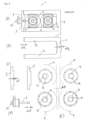
- Figure 6 illustrates the embodiment of Figure 5 in elevation (6A) and plan (6B) view, to further clarify the arrangement of parts. Like elements are again correspondingly numbered.
- each end of the rollers 4, 7 has the assembly illustrated in Figure 6A .
- Figure 7 illustrates the effect of product loading and thermal expansion on the various elements of the assembly of Figure 6 , in a way analogous to Figure 3 . Again, like elements are numbered correspondingly.
- any change in the length of the legs 13 of the frame 2 due to temperature change or contraction when the tensile load reduces when the product load is removed is compensated for by the force applied by the push rod 17; additionally, as the variable width spacer (and in this embodiment, the load cell) are located between the two bearing housings 6, 8, any change in length cannot in any case cause the rollers to move together.
- the same is true for any deformation of the yoke.
- the only change in roller separation upon release of the product load can be the movement of the roller shafts 14 in their bearings 15, with a magnitude of ⁇ B.
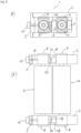
- Figure 8 illustrates an embodiment of a variable width spacer for use in the invention, generally indicated by 18, in abutment with a load cell 33 supported by a load cell mount 20.
- the load cell is preferably provided with a load button, such as a hemispherical protrusion to reduce or eliminate errors that might be caused by misalignment.
- the illustration is partly schematic, for the purpose of illustrating its operation, and engineering details of common workshop practice such as, slide bearings, O-rings etc. are omitted for clarity.
- the variable width spacer 18 comprises a mounting block 21 that supports the various components.
- a first wedge 22 is located between two arms 23 of the mounting block 21.
- the first wedge 22 is provided with a hole therethrough, containing a threaded bushing 24.
- a threaded rod 25 is rotatable by a servo gearhead 26 to cause the first wedge 22 to be moved up and down between the two arms 23.
- a second wedge 27 is mounted for sliding displacement within a keyway 28 in each of the arms 23.
- the angled faces of the two wedges 22, 27 are placed in sliding abutment.
- the slopes of the two angled faces are conveniently the same, to enable the axis of the threaded rod 25 to be perpendicular to the axis of the keyway 28.
- Choice of an appropriate slope is a balance between the amount of adjustment provided by the spacer, and the balance of forces normal to and parallel to the plane of abutment of the two wedges 22, 27.
- a large slope provides a greater range of adjustment but leads to more force parallel to the plane of abutment with a risk that frictional forces between the wedges might be overcome, leading to unwanted relative movement of wedges.
- a smaller slope reduces this risk, and provides finer control, but over a smaller range. This may be mitigated by use of shims between the spacer 18 and one of the bearings 6, 8 as described above.
- the inventors have found that a slope of between 1:10 and 1:20 provides a useful balance, but a consideration of transmitted forces and materials of construction could lead other choices in different circumstances.
- FIG. 8B shows the adjuster 18 with the first wedge 22 moved downwards, causing the second wedge 27 to move outwards.
- the arms 23 extend past the leftmost outer face 19 of the variable width spacer 18 but the operative portion of the load cell 33 and its mount 20 fits between the two arms 23 so that the effective width of the gap adjuster is the distance between the two faces 19.
- Figure 9 illustrates in the same way as Figure 8 an alternative variable width spacer, generally indicated by 18, and again in abutment with a load cell 33. Elements in common with the embodiment of Figure 8 are correspondingly numbered, and will not be described further.
- the sliding wedges are replaced by the combination of a sliding block 29 located in a keyway in each of the arms 23 of the mounting block 21, and a rotatable cam 30 that sits between an inwardly-facing surface 31 of the sliding block 29 and an opposing inner face 32 of the mounting block 21.
- Rotation of the cam by e.g. a servo driven gearhead (not illustrated) causes a corresponding movement of the sliding block 29 within the keyways 28, thereby changing the operation width of the variable width spacer 18.
- Figure 9B shows the arrangement of Figure 9A after the cam has been turned in the direction indicated by the arrow, causing the sliding block 28 to retract within the mounting block 21, thereby decreasing the width between the outer operational faces 19 of the variable width spacer 18.
Landscapes
- Life Sciences & Earth Sciences (AREA)
- Engineering & Computer Science (AREA)
- Food Science & Technology (AREA)
- Rolls And Other Rotary Bodies (AREA)
- Manufacturing And Processing Devices For Dough (AREA)
- Formation And Processing Of Food Products (AREA)
Abstract
Description
- The invention relates to a roller assembly for producing compressed sheet material. The invention especially concerns such an assembly for producing sheet food materials.
- Roller assemblies are often used in the process industries to produce sheet materials or a desired thickness from a starting material comprising a plastic or elastic material. In the food industries such materials would include pasta doughs and doughs for the manufacture of essentially flat products such as savoury snack and biscuits.
- These roller assemblies comprise a pair of rollers arranged to define a gap between them, through which the material to be compressed is passed. Multiple sets of such roller assemblies may be employed in sequence to progressively compress a product into a sheet of desired thickness.
- Despite the seemingly simple operation of such assemblies many considerations need to be taken into account for safe, precise, and practical operation.
-
Figure 1 illustrates a side elevation view of a known roller assembly, generally indicated by 1, and referred to herein as a "screw jack assembly". The assembly 1 comprises aroller support frame 2 and ayoke 3. Mounted in the frame in a fixed position is afirst roller 4, separated from the end of the frame by aspacer 5, abutting the bearinghousing 6 of the first roller. - Also mounted within the
frame 2 is asecond roller 7. Thisroller 7 is mounted for sliding movement in theframe 2, and itsbearing housing 8 is connected to a threadedscrew 9 passing through theyoke 3 and to ajack screw 10 which allows thesecond roller 7 to be moved towards, and away from the first roller to adjust the gap between the faces of each roller. -
Figure 2 illustrates, in schematic plan view, the assembly ofFigure 1 to more clearly illustrate the relation of parts. Like elements already described are correspondingly numbered. It can be seen that aframe 2 and its associated adjustment components are provided at each end of the shafts of each roller. - For many products, the required gap between the rollers is of a similar magnitude to the dimensional changes that components of the assembly might experience under changing operating loads, or changing temperatures. These dimensional changes will be described for the prior art roller assembly described above. The deformations and bearing tolerances illustrated in
Figures 4 , and7 are exaggerated, for clarity. -
Figure 3A illustrates, in schematic elevation view, the screw jack roller assembly 1 already described in relation toFigure 1 . Like elements already described are correspondingly numbered.Figures 3B-3E illustrate various elements of the assembly, to show the dimensional changes that might be experienced under changing operational loads or temperatures. Note thatFigures 3D and 3E are shown at an enlarged scale, for clarity. - In use, when product is being compressed by the rollers, the product exerts a force on the rollers, tending to push them apart. This force can be quite considerable, reaching perhaps several hundred kN/m for some types of dough processing. This force is transmitted to the various components of the system with varying effects.
Figure 3B illustrates theframe 2 of the assembly. Under product load conditions, thelegs 13 of the frame 1 will be under tension, leading to a change in length of ΔF1 (illustrated by the dotted line). So, when the product load is removed, e.g. if the feed is stopped, the rollers will move together by a distance of ΔF1. Likewise, there can be a deformation of the base 11 of the frame when under load, indicated by ΔF2. So, when the product load is removed, the rollers can move together by a further ΔF2. Additionally, the length of thelegs 13 of the frame is also affected by thermal expansion. When running, and under product load, the frame typically equilibrates at a higher temperature than ambient, leading to an additional increase in the length of the legs of ΔT. So, when temperatures fall, the rollers move together by an additional ΔT due to thermal contraction. -
Figure 3C illustrates theyoke 3 of the assembly under product load conditions (dotted) and no-load conditions (solid line). Under product load, compression of the threadedscrew 9 connected to theyoke 3 via thescrew driver motor 10 will case the yoke to deform in a domed fashion as illustrated by the dotted line depiction. The deformation leads to a dimensional change of ΔY. When the product load is removed, theyoke 3 can relax back to its unstressed shape, illustrated by the solid line depiction. So, when the product load is removed, the rollers will move together by an additional distance of ΔY. -
Figure 3D illustrates the threadedscrew 9 andscrew driver 10 in its under-product-load configuration (dotted line). The compressive force applied to the threaded screw leads to a reduction in its length of ΔS. So, when the product load is removed, the rollers will move together by an additional distance of ΔS. - Finally,
Figure 3E illustrates, schematically the tworollers - Thus, for this type of roller assembly, the potential change in gap ΔG when the product load is removed, and the assembly cools is given by ΔG = ΔF1 + ΔF2 + ΔT + ΔY + ΔS + ΔB.
- When the required operational gap between the rollers is small, e.g. to produce a typical thickness of a snack product of e.g. 0.4mm, the magnitude of ΔG is such that the rollers can contact each other when product load is removed. This can cause damage to the rollers, leads to production downtime, and can potentially be hazardous.
- It is an object of the present invention to propose an alternative roller assembly in which the risk of rollers touching when product load is removed is significantly reduced, or even eliminated.
- Accordingly, the invention provides a roller assembly for producing a compressed sheet material, said assembly comprising: (a) a roller support frame; (b) a first roller mountable in a fixed position relative to said frame; (c) a second roller mountable to said frame for sliding displacement relative to said first roller; (d) an actuator mountable to said frame, and arranged to apply force to the shaft bearing of said second roller to urge said second roller towards said first roller; and (e) a variable width spacer located between the shaft bearings of the first and second rollers to limit the minimum separation between said first and second rollers.
- Preferably, said variable width spacer comprises: (a) two adjacent wedges in sliding contact with each other such that the combined width of said wedges changes as the wedges slide relative to each other; and (b) a spacer actuator arranged to reversibly slide said wedges relative to each other to vary the width of said spacer.
- Alternatively, said variable width spacer comprises: (a) a cam; and (b) a spacer actuator arranged to reversibly rotate said cam to vary the width of said spacer.
- In either case, it is preferred that said actuator comprises a hydraulic ram.
- In any aspect of the invention it is further preferred that the roller assembly further comprises a load cell to measure and transmit the force exerted on said variable width spacer by said roller shaft bearings to a controller.
- More preferably, the roller assembly further comprises a force sensor to measure and transmit the force exerted by said actuator on the shaft bearing of said second roller to a controller.
- Where a load cell is provided it is preferred that said controller is configured to calculate the force exerted on the rollers from compressing said sheet material by subtracting the load cell force from either a pre-set or measured actuator force.
- The scope of the invention also includes apparatus for manufacturing a sheet food material comprising a roller assembly of the invention.
- The scope of the invention also includes a method of manufacturing a sheet food material comprising the step of passing a food material through a roller assembly of the invention.
- The invention will be described with reference to the accompanying drawings, in which:
-
Figures 1 and 2 illustrate a known roller assembly in elevation and plan view respectively; -
Figure 3 illustrates the known roller assembly ofFigures 1 and 2 , the deformations experienced during operation, and movement of roller shafts in their bearings; -
Figures 4 and 5 illustrate roller assemblies of the invention, in elevation view; -
Figure 6 illustrates a roller assembly of the invention in elevation and plan view; -
Figure 7 illustrates a roller assembly of the invention, in elevation view, and movement of roller shafts in their bearings; and -
Figures 8 and9 illustrate gap adjusters forming part of a roller assembly of the invention. -
Figure 4 illustrates, in elevation view, an embodiment of roller assembly of the invention, generally indicated by 1. Like elements already described in relation to the above prior art devices are correspondingly numbered. Elements are illustrated in a slightly spaced-apart relationship for clarity. - The roller assembly 1 comprises a
roller support frame 2 in which is mounted a first roller in a fixed position relative to the frame. In this embodiment, aspacer 5 is provided between the bearinghousing 6 of the first roller and the inner surface of theframe 2 to allow coarse adjustment of the gap between the rollers. - A
second roller 7 is mounted in the frame for sliding displacement relative to thefirst roller 4 so that the gap between the faces of therollers actuator 16 is provided, mounted to ayoke 3 attached to theframe 2 to apply force to the shaft bearing of thesecond roller 7. In this embodiment, a hydraulic actuator (e.g. a hydraulic ram) is used to apply force via apush rod 17 that passes through a hole in theyoke 3 and bears on a surface of the bearinghousing 8 of thesecond roller 7. The force is thereby transferred onto theshaft bearing 15. On commissioning the roller assembly for any particular purpose, the force exerted by the actuator is chosen to be greater than the force exerted on the rollers by the product, to ensure that the rollers do not move apart under force of the product. Typically, the force exerted by the actuator might be chosen to 5%, 10, or even 20% above the expected product force. - A
variable width spacer 18 is located between theshaft bearings 15 of the first and second rollers. In this embodiment, thespacer 18 is mounted between the twobearing housings opposite side 19 of thespacer 18 abutting its adjacent bearing housing. Alternative designs for such variable width spacer are discussed below, but in principle the spacer can be controlled (e.g. by a control signal) to vary the width between the opposite faces 19 of thespacer 18 to limit the minimum separation of the first 4 and second 7 rollers.' - If variation of the gap between the
rollers variable width spacer 18, a shim, or multiple shims (not illustrated) can be positioned between thespacer 18 and one or both of thebearing housings -
Figure 5 illustrates, again in elevation view, a second embodiment of roller assembly of the invention, generally indicated by 1. Like elements already described in relation to other assemblies are correspondingly numbered, and again, elements are illustrated in a slightly spaced-apart relationship for clarity. - This embodiment is largely the same as that of
Figure 4 , and common elements will not be described unnecessarily. This embodiment has an additional feature in that a load cell is mounted between one of thefaces 19 of thevariable width spacer 18 and itsadjacent bearing housing 8. This can measure the force required to keep the roller bearing tight against thespacer 18, which will vary depending on the presence and physical properties of product being compressed in the gap between the faces of the rollers. The force exerted by the product on the rollers is given by the load cell reading minus the hydraulic force applied to thesecond bearing housing 8. - A signal can therefore be transmitted from the load cell to a controller for monitoring and control purposes. For example, it could be used to control the moisture content or temperature of the product (e.g. a dough) entering the roller assembly, to maintain a desired product force for a given gap width. Alternatively, it could trigger an alert to process operators if the calculated product force varies outside a predetermined range. The product load can either be calculated from the load cell reading minus a known, pre-set hydraulic force, or by subtracting the load cell force from a measured hydraulic force.
-
Figure 6 illustrates the embodiment ofFigure 5 in elevation (6A) and plan (6B) view, to further clarify the arrangement of parts. Like elements are again correspondingly numbered. - It can be seen in
Figure 6B that each end of therollers Figure 6A . -
Figure 7 illustrates the effect of product loading and thermal expansion on the various elements of the assembly ofFigure 6 , in a way analogous toFigure 3 . Again, like elements are numbered correspondingly. - Any change in the length of the
legs 13 of theframe 2 due to temperature change or contraction when the tensile load reduces when the product load is removed is compensated for by the force applied by thepush rod 17; additionally, as the variable width spacer (and in this embodiment, the load cell) are located between the twobearing housings roller shafts 14 in theirbearings 15, with a magnitude of ΔB. The greatest possible change in gap ΔG when the product load is removed, and the assembly cools is therefore given by ΔG = ΔB, using the same nomenclature as above. - It can be seen therefore, that the risk of rollers touching when a product load is removed is greatly reduced. If the required product gap is less than the AG, then the risk is removed altogether.
-
Figure 8 illustrates an embodiment of a variable width spacer for use in the invention, generally indicated by 18, in abutment with aload cell 33 supported by aload cell mount 20. The load cell is preferably provided with a load button, such as a hemispherical protrusion to reduce or eliminate errors that might be caused by misalignment. The illustration is partly schematic, for the purpose of illustrating its operation, and engineering details of common workshop practice such as, slide bearings, O-rings etc. are omitted for clarity. - The
variable width spacer 18 comprises a mountingblock 21 that supports the various components. Afirst wedge 22 is located between twoarms 23 of the mountingblock 21. Thefirst wedge 22 is provided with a hole therethrough, containing a threadedbushing 24. A threadedrod 25 is rotatable by aservo gearhead 26 to cause thefirst wedge 22 to be moved up and down between the twoarms 23. - A
second wedge 27 is mounted for sliding displacement within akeyway 28 in each of thearms 23. The angled faces of the twowedges - The slopes of the two angled faces are conveniently the same, to enable the axis of the threaded
rod 25 to be perpendicular to the axis of thekeyway 28. Choice of an appropriate slope is a balance between the amount of adjustment provided by the spacer, and the balance of forces normal to and parallel to the plane of abutment of the twowedges spacer 18 and one of thebearings - In this way, when the
servo gearhead 26 rotates the threadedrod 25 located in thebushing 24, thefirst wedge 22 slides relative to the first wedge and the geometry of the wedges causes the overall width of the gap adjuster to change.Figure 8B shows theadjuster 18 with thefirst wedge 22 moved downwards, causing thesecond wedge 27 to move outwards. In this embodiment thearms 23 extend past the leftmostouter face 19 of thevariable width spacer 18 but the operative portion of theload cell 33 and itsmount 20 fits between the twoarms 23 so that the effective width of the gap adjuster is the distance between the two faces 19. -
Figure 9 illustrates in the same way asFigure 8 an alternative variable width spacer, generally indicated by 18, and again in abutment with aload cell 33. Elements in common with the embodiment ofFigure 8 are correspondingly numbered, and will not be described further. In this embodiment, the sliding wedges are replaced by the combination of a slidingblock 29 located in a keyway in each of thearms 23 of the mountingblock 21, and arotatable cam 30 that sits between an inwardly-facingsurface 31 of the slidingblock 29 and an opposinginner face 32 of the mountingblock 21. Rotation of the cam by e.g. a servo driven gearhead (not illustrated) causes a corresponding movement of the slidingblock 29 within thekeyways 28, thereby changing the operation width of thevariable width spacer 18.Figure 9B shows the arrangement ofFigure 9A after the cam has been turned in the direction indicated by the arrow, causing the slidingblock 28 to retract within the mountingblock 21, thereby decreasing the width between the outeroperational faces 19 of thevariable width spacer 18. - Also provided are the following technology aspects:
- 1. A roller assembly for producing a compressed sheet material, said assembly comprising:
- (a) a roller support frame;
- (b) a first roller mountable in a fixed position relative to said frame;
- (c) a second roller mountable to said frame for sliding displacement relative to said first roller;
- (d) an actuator mountable to said frame, and arranged to apply force to the shaft bearing of said second roller to urge said second roller towards said first roller; and
- (e) a variable width spacer located between the shaft bearings of the first and second rollers to limit the minimum separation between said first and second rollers.
- 2. The roller assembly of Aspect 1 wherein said variable width spacer comprises:
- (a) two adjacent wedges in sliding contact with each other such that the combined width of said wedges changes as the wedges slide relative to each other; and
- (b) a spacer actuator arranged to reversibly slide said wedges relative to each other to vary the width of said spacer.
- 3. The roller assembly of Aspect 1 wherein said variable width spacer comprises:
- (a) a cam; and
- (b) a spacer actuator arranged to reversibly rotate said cam to vary the width of said spacer.
- 4. The roller assembly of any preceding Aspect wherein said actuator comprises a hydraulic ram.
- 5. The roller assembly of any preceding Aspect further comprising a load cell to measure and transmit the force exerted on said variable width spacer by said roller shaft bearings to a controller.
- 6. The roller assembly of any preceding Aspect further comprising a force sensor to measure and transmit the force exerted by said actuator on the shaft bearing of said second roller to a controller.
- 7. The roller assembly of
Aspect 5 wherein said controller is configured to calculate the force exerted on the rollers from compressing said sheet material by subtracting the load cell force from either a pre-set or measured actuator force. - 8. Apparatus for manufacturing a sheet food material comprising a roller assembly of any preceding Aspect.
- 9. A method of manufacturing a sheet food material comprising the step of passing a food material through a roller assembly of any preceding Aspect.
Claims (7)
- A roller assembly for producing a compressed sheet material, said assembly comprising:(a) a roller support frame;(b) a first roller mountable in a fixed position relative to said frame;(c) a second roller mountable to said frame for sliding displacement relative to said first roller;(d) an actuator mountable to said frame, and arranged to apply force to the shaft bearing of said second roller to urge said second roller towards said first roller; and(e) a variable width spacer located between the shaft bearings of the first and second rollers to limit the minimum separation between said first and second rollers,wherein said variable width spacer comprises a cam and a spacer actuator arranged to reversibly rotate said cam to vary the width of said spacer.
- The roller assembly of Claim 1wherein said actuator comprises a hydraulic ram.
- The roller assembly of any preceding Claim further comprising a load cell to measure and transmit the force exerted on said variable width spacer by said roller shaft bearings to a controller.
- The roller assembly of any preceding Claim further comprising a force sensor to measure and transmit the force exerted by said actuator on the shaft bearing of said second roller to a controller.
- The roller assembly of Claim 3 wherein said controller is configured to calculate the force exerted on the rollers from compressing said sheet material by subtracting the load cell force from either a pre-set or measured actuator force.
- Apparatus for manufacturing a sheet food material comprising a roller assembly of any preceding claim.
- A method of manufacturing a sheet food material comprising the step of passing a food material through a roller assembly of any preceding claim.
Applications Claiming Priority (3)
| Application Number | Priority Date | Filing Date | Title |
|---|---|---|---|
| GB2007161.9A GB2594984B (en) | 2020-05-14 | 2020-05-14 | Improvements in roller apparatus |
| PCT/EP2021/062836 WO2021229056A1 (en) | 2020-05-14 | 2021-05-14 | Roller apparatus comprising a variable-width spacer |
| EP21727395.2A EP4149265A1 (en) | 2020-05-14 | 2021-05-14 | Roller apparatus comprising a variable-width spacer |
Related Parent Applications (1)
| Application Number | Title | Priority Date | Filing Date |
|---|---|---|---|
| EP21727395.2A Division EP4149265A1 (en) | 2020-05-14 | 2021-05-14 | Roller apparatus comprising a variable-width spacer |
Publications (3)
| Publication Number | Publication Date |
|---|---|
| EP4241564A2 true EP4241564A2 (en) | 2023-09-13 |
| EP4241564A3 EP4241564A3 (en) | 2023-12-06 |
| EP4241564B1 EP4241564B1 (en) | 2025-07-23 |
Family
ID=71135292
Family Applications (2)
| Application Number | Title | Priority Date | Filing Date |
|---|---|---|---|
| EP21727395.2A Pending EP4149265A1 (en) | 2020-05-14 | 2021-05-14 | Roller apparatus comprising a variable-width spacer |
| EP23182057.2A Active EP4241564B1 (en) | 2020-05-14 | 2021-05-14 | Roller apparatus comprising a variable-width spacer |
Family Applications Before (1)
| Application Number | Title | Priority Date | Filing Date |
|---|---|---|---|
| EP21727395.2A Pending EP4149265A1 (en) | 2020-05-14 | 2021-05-14 | Roller apparatus comprising a variable-width spacer |
Country Status (10)
| Country | Link |
|---|---|
| US (1) | US20230232842A1 (en) |
| EP (2) | EP4149265A1 (en) |
| CN (1) | CN115768267B (en) |
| CA (1) | CA3178423A1 (en) |
| ES (1) | ES3037844T3 (en) |
| GB (1) | GB2594984B (en) |
| MX (2) | MX2022014314A (en) |
| PL (1) | PL4241564T3 (en) |
| PT (1) | PT4241564T (en) |
| WO (1) | WO2021229056A1 (en) |
Family Cites Families (22)
| Publication number | Priority date | Publication date | Assignee | Title |
|---|---|---|---|---|
| US3684332A (en) * | 1971-03-29 | 1972-08-15 | Procter & Gamble | Apparatus for adjusting the center distance between bearing support members |
| US3883283A (en) * | 1973-05-29 | 1975-05-13 | Casa Herrara Inc | Flour dough sheet forming and conveying systems |
| US4481800A (en) * | 1982-10-22 | 1984-11-13 | Kennecott Corporation | Cold rolling mill for metal strip |
| JPH01206942A (en) * | 1988-02-15 | 1989-08-21 | Rheon Autom Mach Co Ltd | Method and apparatus for carrying out extension molding of bread dough or the like |
| CH672082A5 (en) * | 1988-07-16 | 1989-10-31 | Guenther Alich | |
| DE4002715C1 (en) * | 1990-01-31 | 1991-07-04 | A. Fritsch Gmbh & Co Kg, 8711 Markt Einersheim, De | |
| CH685019A5 (en) * | 1991-11-21 | 1995-02-28 | Daverio Ag | Bearing assembly with a radial bearing. |
| US5498148A (en) * | 1994-08-10 | 1996-03-12 | Recot, Inc. | Apparatus for forming sheets of material having a uniform thickness and cutting individual portions therefrom |
| US5498433A (en) * | 1995-04-18 | 1996-03-12 | Recot, Inc. | Apparatus and process for forming sheets of material having a uniform thickness |
| US5674543A (en) * | 1995-11-02 | 1997-10-07 | Casa Herrera, Inc. | Dough sheeter with improved pinch-point adjustment mechanism |
| JPH10184664A (en) * | 1996-12-24 | 1998-07-14 | Toshiba Mach Co Ltd | Roll bending device |
| JP3949992B2 (en) * | 2002-04-02 | 2007-07-25 | レオン自動機株式会社 | Method and apparatus for spreading food dough |
| US7217382B2 (en) * | 2004-08-16 | 2007-05-15 | Frito-Lay North America, Inc. | Sheeter gap adjustment and hydraulic operation |
| CN102452170A (en) * | 2010-10-22 | 2012-05-16 | 张家港市贝尔机械有限公司 | Wedge-type gap adjustment mechanism of plastic sheet calender |
| US9073282B2 (en) * | 2012-11-02 | 2015-07-07 | The Procter & Gamble Company | Process for controlling the nip force/pressure between two rotating cylinders |
| EP2746024B1 (en) * | 2012-12-21 | 2015-05-27 | Reifenhäuser GmbH & Co. KG Maschinenfabrik | Roller frame |
| CN206776628U (en) * | 2017-05-23 | 2017-12-22 | 常州市墅乐厨具有限公司 | A kind of adjustable surface pressure body of musculus cutaneus thickness and its oodle maker |
| CN207707174U (en) * | 2017-12-04 | 2018-08-10 | 成都香贝儿食品有限公司 | A kind of soft bread production line prepressing device |
| CN107927035A (en) * | 2017-12-26 | 2018-04-20 | 山东泗水海韵粮机有限公司 | A kind of rotary noodle press with the accurate regulatory function of pressure surface roller spacing |
| CN108651556A (en) * | 2018-07-04 | 2018-10-16 | 王晓杰 | Dough processes the precompressed collating unit of conveying production line |
| CN109463409A (en) * | 2018-11-30 | 2019-03-15 | 安徽中乐食品机械有限公司 | A kind of adjustable power floating roller device for noodle press |
| CN210436593U (en) * | 2019-07-12 | 2020-05-01 | 常州金纬片板设备制造有限公司 | Roller clearance fine adjuster and calender applying same |
-
2020
- 2020-05-14 GB GB2007161.9A patent/GB2594984B/en active Active
-
2021
- 2021-05-14 WO PCT/EP2021/062836 patent/WO2021229056A1/en not_active Ceased
- 2021-05-14 PL PL23182057.2T patent/PL4241564T3/en unknown
- 2021-05-14 EP EP21727395.2A patent/EP4149265A1/en active Pending
- 2021-05-14 MX MX2022014314A patent/MX2022014314A/en unknown
- 2021-05-14 PT PT231820572T patent/PT4241564T/en unknown
- 2021-05-14 ES ES23182057T patent/ES3037844T3/en active Active
- 2021-05-14 EP EP23182057.2A patent/EP4241564B1/en active Active
- 2021-05-14 US US17/924,805 patent/US20230232842A1/en active Pending
- 2021-05-14 CN CN202180045391.7A patent/CN115768267B/en active Active
- 2021-05-14 CA CA3178423A patent/CA3178423A1/en active Pending
-
2022
- 2022-11-14 MX MX2025012596A patent/MX2025012596A/en unknown
Also Published As
| Publication number | Publication date |
|---|---|
| GB2594984B (en) | 2022-06-08 |
| EP4241564B1 (en) | 2025-07-23 |
| CA3178423A1 (en) | 2021-11-18 |
| WO2021229056A1 (en) | 2021-11-18 |
| GB202007161D0 (en) | 2020-07-01 |
| ES3037844T3 (en) | 2025-10-07 |
| MX2022014314A (en) | 2022-12-13 |
| CN115768267B (en) | 2024-09-13 |
| US20230232842A1 (en) | 2023-07-27 |
| EP4149265A1 (en) | 2023-03-22 |
| EP4241564A3 (en) | 2023-12-06 |
| GB2594984A (en) | 2021-11-17 |
| PL4241564T3 (en) | 2025-09-22 |
| CN115768267A (en) | 2023-03-07 |
| MX2025012596A (en) | 2025-11-03 |
| PT4241564T (en) | 2025-08-13 |
Similar Documents
| Publication | Publication Date | Title |
|---|---|---|
| US4553461A (en) | Rotary web processing apparatus | |
| CA2709685C (en) | Prestressed rolling mill housing assembly with improved operational features | |
| US9943895B2 (en) | Rolling device, resulting electrolyte film, and power storage assembly formed from at least one thus-rolled film | |
| EP0194628B1 (en) | Double drum type continuous casting machine | |
| CA3057412C (en) | Apparatus and method to guide metal products | |
| US4348952A (en) | Cross axis mechanism | |
| EP4241564B1 (en) | Roller apparatus comprising a variable-width spacer | |
| EP1042084B1 (en) | Method to eliminate the play between chocks and relative support blocks in four-high rolling stands and relative device | |
| KR20020016781A (en) | Adjustable monitoring guide | |
| CN101039581B (en) | Tablet press lash adjustment and hydraulic operation | |
| US3991597A (en) | Method and device for adjusting forming rolls in a helical seam pipe mill | |
| AU2011208917B2 (en) | Belt run control device, in particular of a forming and cooling device | |
| US4446712A (en) | Propped cantilevered roll stand | |
| CN117139365A (en) | High-speed aluminum strip production is with thin adjusting device that rolls | |
| GB2153277A (en) | Load-transfer mechanism | |
| JPH05308A (en) | Variable width rolling roll | |
| JPS598445B2 (en) | Roll axial position control method and device |
Legal Events
| Date | Code | Title | Description |
|---|---|---|---|
| PUAI | Public reference made under article 153(3) epc to a published international application that has entered the european phase |
Free format text: ORIGINAL CODE: 0009012 |
|
| STAA | Information on the status of an ep patent application or granted ep patent |
Free format text: STATUS: THE APPLICATION HAS BEEN PUBLISHED |
|
| AC | Divisional application: reference to earlier application |
Ref document number: 4149265 Country of ref document: EP Kind code of ref document: P |
|
| AK | Designated contracting states |
Kind code of ref document: A2 Designated state(s): AL AT BE BG CH CY CZ DE DK EE ES FI FR GB GR HR HU IE IS IT LI LT LU LV MC MK MT NL NO PL PT RO RS SE SI SK SM TR |
|
| P01 | Opt-out of the competence of the unified patent court (upc) registered |
Effective date: 20230921 |
|
| PUAL | Search report despatched |
Free format text: ORIGINAL CODE: 0009013 |
|
| AK | Designated contracting states |
Kind code of ref document: A3 Designated state(s): AL AT BE BG CH CY CZ DE DK EE ES FI FR GB GR HR HU IE IS IT LI LT LU LV MC MK MT NL NO PL PT RO RS SE SI SK SM TR |
|
| RIC1 | Information provided on ipc code assigned before grant |
Ipc: A21C 3/02 20060101AFI20231027BHEP |
|
| STAA | Information on the status of an ep patent application or granted ep patent |
Free format text: STATUS: REQUEST FOR EXAMINATION WAS MADE |
|
| 17P | Request for examination filed |
Effective date: 20240514 |
|
| RBV | Designated contracting states (corrected) |
Designated state(s): AL AT BE BG CH CY CZ DE DK EE ES FI FR GB GR HR HU IE IS IT LI LT LU LV MC MK MT NL NO PL PT RO RS SE SI SK SM TR |
|
| GRAP | Despatch of communication of intention to grant a patent |
Free format text: ORIGINAL CODE: EPIDOSNIGR1 |
|
| STAA | Information on the status of an ep patent application or granted ep patent |
Free format text: STATUS: GRANT OF PATENT IS INTENDED |
|
| INTG | Intention to grant announced |
Effective date: 20250404 |
|
| GRAS | Grant fee paid |
Free format text: ORIGINAL CODE: EPIDOSNIGR3 |
|
| GRAA | (expected) grant |
Free format text: ORIGINAL CODE: 0009210 |
|
| STAA | Information on the status of an ep patent application or granted ep patent |
Free format text: STATUS: THE PATENT HAS BEEN GRANTED |
|
| AC | Divisional application: reference to earlier application |
Ref document number: 4149265 Country of ref document: EP Kind code of ref document: P |
|
| AK | Designated contracting states |
Kind code of ref document: B1 Designated state(s): AL AT BE BG CH CY CZ DE DK EE ES FI FR GB GR HR HU IE IS IT LI LT LU LV MC MK MT NL NO PL PT RO RS SE SI SK SM TR |
|
| REG | Reference to a national code |
Ref country code: GB Ref legal event code: FG4D |
|
| REG | Reference to a national code |
Ref country code: CH Ref legal event code: EP |
|
| REG | Reference to a national code |
Ref country code: IE Ref legal event code: FG4D Ref country code: PT Ref legal event code: SC4A Ref document number: 4241564 Country of ref document: PT Date of ref document: 20250813 Kind code of ref document: T Free format text: AVAILABILITY OF NATIONAL TRANSLATION Effective date: 20250806 |
|
| REG | Reference to a national code |
Ref country code: DE Ref legal event code: R096 Ref document number: 602021034894 Country of ref document: DE |
|
| REG | Reference to a national code |
Ref country code: NL Ref legal event code: FP |
|
| REG | Reference to a national code |
Ref country code: ES Ref legal event code: FG2A Ref document number: 3037844 Country of ref document: ES Kind code of ref document: T3 Effective date: 20251007 |
|
| REG | Reference to a national code |
Ref country code: AT Ref legal event code: MK05 Ref document number: 1815424 Country of ref document: AT Kind code of ref document: T Effective date: 20250723 |
|
| PG25 | Lapsed in a contracting state [announced via postgrant information from national office to epo] |
Ref country code: IS Free format text: LAPSE BECAUSE OF FAILURE TO SUBMIT A TRANSLATION OF THE DESCRIPTION OR TO PAY THE FEE WITHIN THE PRESCRIBED TIME-LIMIT Effective date: 20251123 |
|
| PG25 | Lapsed in a contracting state [announced via postgrant information from national office to epo] |
Ref country code: NO Free format text: LAPSE BECAUSE OF FAILURE TO SUBMIT A TRANSLATION OF THE DESCRIPTION OR TO PAY THE FEE WITHIN THE PRESCRIBED TIME-LIMIT Effective date: 20251023 |
|
| REG | Reference to a national code |
Ref country code: LT Ref legal event code: MG9D |
|
| PG25 | Lapsed in a contracting state [announced via postgrant information from national office to epo] |
Ref country code: AT Free format text: LAPSE BECAUSE OF FAILURE TO SUBMIT A TRANSLATION OF THE DESCRIPTION OR TO PAY THE FEE WITHIN THE PRESCRIBED TIME-LIMIT Effective date: 20250723 |
|
| PG25 | Lapsed in a contracting state [announced via postgrant information from national office to epo] |
Ref country code: FI Free format text: LAPSE BECAUSE OF FAILURE TO SUBMIT A TRANSLATION OF THE DESCRIPTION OR TO PAY THE FEE WITHIN THE PRESCRIBED TIME-LIMIT Effective date: 20250723 |
|
| PG25 | Lapsed in a contracting state [announced via postgrant information from national office to epo] |
Ref country code: HR Free format text: LAPSE BECAUSE OF FAILURE TO SUBMIT A TRANSLATION OF THE DESCRIPTION OR TO PAY THE FEE WITHIN THE PRESCRIBED TIME-LIMIT Effective date: 20250723 |
|
| PG25 | Lapsed in a contracting state [announced via postgrant information from national office to epo] |
Ref country code: GR Free format text: LAPSE BECAUSE OF FAILURE TO SUBMIT A TRANSLATION OF THE DESCRIPTION OR TO PAY THE FEE WITHIN THE PRESCRIBED TIME-LIMIT Effective date: 20251024 |
|
| PG25 | Lapsed in a contracting state [announced via postgrant information from national office to epo] |
Ref country code: SE Free format text: LAPSE BECAUSE OF FAILURE TO SUBMIT A TRANSLATION OF THE DESCRIPTION OR TO PAY THE FEE WITHIN THE PRESCRIBED TIME-LIMIT Effective date: 20250723 |
|
| PG25 | Lapsed in a contracting state [announced via postgrant information from national office to epo] |
Ref country code: LV Free format text: LAPSE BECAUSE OF FAILURE TO SUBMIT A TRANSLATION OF THE DESCRIPTION OR TO PAY THE FEE WITHIN THE PRESCRIBED TIME-LIMIT Effective date: 20250723 |
|
| PG25 | Lapsed in a contracting state [announced via postgrant information from national office to epo] |
Ref country code: BG Free format text: LAPSE BECAUSE OF FAILURE TO SUBMIT A TRANSLATION OF THE DESCRIPTION OR TO PAY THE FEE WITHIN THE PRESCRIBED TIME-LIMIT Effective date: 20250723 |
|
| PG25 | Lapsed in a contracting state [announced via postgrant information from national office to epo] |
Ref country code: RS Free format text: LAPSE BECAUSE OF FAILURE TO SUBMIT A TRANSLATION OF THE DESCRIPTION OR TO PAY THE FEE WITHIN THE PRESCRIBED TIME-LIMIT Effective date: 20251023 |
|
| PG25 | Lapsed in a contracting state [announced via postgrant information from national office to epo] |
Ref country code: SM Free format text: LAPSE BECAUSE OF FAILURE TO SUBMIT A TRANSLATION OF THE DESCRIPTION OR TO PAY THE FEE WITHIN THE PRESCRIBED TIME-LIMIT Effective date: 20250723 |
|
| PG25 | Lapsed in a contracting state [announced via postgrant information from national office to epo] |
Ref country code: DK Free format text: LAPSE BECAUSE OF FAILURE TO SUBMIT A TRANSLATION OF THE DESCRIPTION OR TO PAY THE FEE WITHIN THE PRESCRIBED TIME-LIMIT Effective date: 20250723 |
|
| PG25 | Lapsed in a contracting state [announced via postgrant information from national office to epo] |
Ref country code: CZ Free format text: LAPSE BECAUSE OF FAILURE TO SUBMIT A TRANSLATION OF THE DESCRIPTION OR TO PAY THE FEE WITHIN THE PRESCRIBED TIME-LIMIT Effective date: 20250723 |
|
| PG25 | Lapsed in a contracting state [announced via postgrant information from national office to epo] |
Ref country code: SK Free format text: LAPSE BECAUSE OF FAILURE TO SUBMIT A TRANSLATION OF THE DESCRIPTION OR TO PAY THE FEE WITHIN THE PRESCRIBED TIME-LIMIT Effective date: 20250723 Ref country code: EE Free format text: LAPSE BECAUSE OF FAILURE TO SUBMIT A TRANSLATION OF THE DESCRIPTION OR TO PAY THE FEE WITHIN THE PRESCRIBED TIME-LIMIT Effective date: 20250723 |