EP4240262B1 - Biplanar forceps reducers - Google Patents
Biplanar forceps reducers Download PDFInfo
- Publication number
- EP4240262B1 EP4240262B1 EP21810005.5A EP21810005A EP4240262B1 EP 4240262 B1 EP4240262 B1 EP 4240262B1 EP 21810005 A EP21810005 A EP 21810005A EP 4240262 B1 EP4240262 B1 EP 4240262B1
- Authority
- EP
- European Patent Office
- Prior art keywords
- tube
- instrument
- rod
- arm
- reducer
- Prior art date
- Legal status (The legal status is an assumption and is not a legal conclusion. Google has not performed a legal analysis and makes no representation as to the accuracy of the status listed.)
- Active
Links
Images



















Classifications
-
- A—HUMAN NECESSITIES
- A61—MEDICAL OR VETERINARY SCIENCE; HYGIENE
- A61B—DIAGNOSIS; SURGERY; IDENTIFICATION
- A61B17/00—Surgical instruments, devices or methods
- A61B17/56—Surgical instruments or methods for treatment of bones or joints; Devices specially adapted therefor
- A61B17/58—Surgical instruments or methods for treatment of bones or joints; Devices specially adapted therefor for osteosynthesis, e.g. bone plates, screws or setting implements
- A61B17/68—Internal fixation devices, including fasteners and spinal fixators, even if a part thereof projects from the skin
- A61B17/70—Spinal positioners or stabilisers, e.g. stabilisers comprising fluid filler in an implant
- A61B17/7074—Tools specially adapted for spinal fixation operations other than for bone removal or filler handling
- A61B17/7083—Tools for guidance or insertion of tethers, rod-to-anchor connectors, rod-to-rod connectors, or longitudinal elements
- A61B17/7086—Rod reducers, i.e. devices providing a mechanical advantage to allow a user to force a rod into or onto an anchor head other than by means of a rod-to-bone anchor locking element; rod removers
-
- A—HUMAN NECESSITIES
- A61—MEDICAL OR VETERINARY SCIENCE; HYGIENE
- A61B—DIAGNOSIS; SURGERY; IDENTIFICATION
- A61B17/00—Surgical instruments, devices or methods
- A61B17/56—Surgical instruments or methods for treatment of bones or joints; Devices specially adapted therefor
- A61B17/58—Surgical instruments or methods for treatment of bones or joints; Devices specially adapted therefor for osteosynthesis, e.g. bone plates, screws or setting implements
- A61B17/88—Osteosynthesis instruments; Methods or means for implanting or extracting internal or external fixation devices
- A61B17/8875—Screwdrivers, spanners or wrenches
Definitions
- This disclosure relates generally to surgical instruments and, more particularly, to surgical instruments utilized to move one object relative to another, e.g., move a rod or spinal fixation element relative to an implanted bone anchor or other spinal fixation construct component during spine surgery.
- fixation constructs are often assembled to hold the spine in a desired shape.
- Such constructs often include a plurality of implanted bone anchors along multiple vertebrae and a connecting spinal fixation element, such as a rod, that is received within a head of each of the bone anchors and secured using a set screw.
- the bone anchors are first implanted in the vertebrae, a rod is then positioned relative to the bone anchor heads, and set screws applied to secure the rod relative to each bone anchor.
- a rod can be positioned offset from a bone anchor head both dorsally and medially-laterally such that the rod must be translated in both the sagittal plane and the coronal plane to capture it with the bone anchor head.
- This challenge can be particularly prevalent in procedures to correct deformities, as longer fixation constructs are often used along with uniplanar bone anchor heads that pivot in only one direction, though similar challenges can be faced when using bone anchor heads that move polyaxially as well.
- a first instrument can be utilized to laterally translate a rod over a bone anchor head, and axial reduction of the rod into the bone anchor head can be performed with a second instrument. Often this is accomplished by attaching a lateral reducing instrument to a first bone anchor to move the rod over one or more bone anchors along a portion of a spinal fixation construct. An axial reducer can then be attached to an adjacent bone anchor and used to translate the rod axially into the bone anchor head.
- the biplanar forceps reducer instruments disclosed herein can engage an implant, such as a bone anchor receiver head, and reduce or move a spinal fixation element, such as a rod, in two planes to move the rod into a channel formed in the receiver head. Further, the biplanar forceps reducer instruments disclosed herein can allow for introduction and tightening of a set screw using an inserter that can pass through a cannulated tube of the reducer.
- the low profile and biplanar reduction functionality can allow a single type of reducer instrument to couple with each bone anchor along a spinal fixation construct and remain in position until the construct is secured in position.
- a surgical instrument can include a first arm having a proximal end, a distal end, and a housing disposed therebetween, the housing including a threaded lumen defining a longitudinal axis, a second arm having a proximal end and a distal end, the second arm pivotably coupled to the first arm, a tube having a threaded outer surface portion disposed within the threaded lumen, a depth stop formed proximal to the threaded portion, and a drive feature at a proximal end of the tube configured to removably couple with a driver to impart torque to the tube, and a rod-engaging tip rotatably coupled to a distal end of the tube, wherein the first and second arms are configured to translate a spinal fixation element laterally toward the longitudinal axis when pivoted toward one another and the rod-engaging tip is configured to translate the spinal fixation element axially along the longitudinal axis when the tube is rotated relative to the housing.
- the depth stop can define a maximum outer diameter of the tube.
- the depth stop can be a shoulder formed around at least a portion of the circumference of the tube.
- the lumen can include continuous threads formed around a circumference thereof.
- an inner lumen of the tube can be accessible from a proximal end of the tube through the drive feature.
- the rod-engaging tip can include an inner lumen coaxially disposed with the inner lumen of the tube.
- the rod-engaging tip can include an opening formed in a distal portion of a sidewall to facilitate viewing contents of an inner lumen of the rod-engaging tip.
- a distal end of at least one of the first and second arms can include a protrusion configured to extend into a recess of a bone anchor receiver member.
- the protrusion can be a pin disposed in a bore formed in the distal end of at least one of the first and second arms.
- the protrusion can be a ridge extending across a width of the arm. The ridge or other protrusion can extend across an entire width of the arm or, in some embodiments, can extend across only a portion of a width of the arm or include one or more breaks along its length.
- the protrusion can be disposed proximal to a distal-most end of the arm and an inner surface of the arm distal to the protrusion can have a conical tapering profile.
- the inner surface of the arm can include sidewalls extending outward from the inner surface at lateral ends of the arm, and opposed, inward-facing surfaces of each sidewall can have a planar tapering profile.
- a surgical method can include positioning a first arm of a reducer instrument against a bone anchor receiver member, as well as positioning a second arm of the reducer instrument against a spinal fixation element.
- the method can further include positioning a threaded outer surface portion of a tube of the reducer instrument within a threaded lumen formed in a housing of the first arm of the reducer instrument.
- the method can also include pivoting the first and second arms of the reducer instrument toward one another to translate the spinal fixation element laterally toward a longitudinal axis defined by the threaded lumen.
- the method can further include engaging a lock to maintain a position of the first and second arms relative to one another after pivoting the first and second arms toward one another.
- the instrument can further include a rod-engaging tip rotatably coupled to a distal end of the tube, the rod-engaging tip being constrained against rotation relative to the housing by a protrusion coupled to the housing that is received in a recess of the rod-engaging tip.
- the first and second arms can be configured to translate a spinal fixation element laterally toward the longitudinal axis when pivoted toward one another and the rod-engaging tip can be configured to translate the spinal fixation element axially along the longitudinal axis when the tube is rotated relative to the housing.
- the threads on the outer surface portion of the tube can have a plurality of starts. In some embodiments, the threads on the outer portion of the tube can have three starts. Further, in certain embodiments an outer diameter of the threaded outer surface portion of the tube can be less than or equal to about 45% larger than a diameter of an inner lumen of the tube. In certain embodiments, an outer diameter of the threaded outer surface portion of the tube can be less than or equal to about 40%, about 35%, about 30%, about 25%, or about 20% larger than a diameter of an inner lumen of the tube. Utilizing such a configuration can minimize an outer diameter of the threads of the tube and provide a lower profile instrument to access a surgical site through a smaller opening or with less interference for adjacent anatomy or instrumentation.
- an outer diameter of the threaded outer surface portion of the tube can be less than or equal to about 40%, about 35%, about 30%, about 25%, or about 20% larger than a diameter of an inner lumen of the tube. Utilizing such a configuration can minimize an outer diameter of the threads of the tube and provide a lower profile instrument to access a surgical site through a smaller opening or with less interference for adjacent anatomy or instrumentation.
- the threaded lumen can include continuous threads formed around a circumference thereof.
- the housing can include a protrusion received within a recess of the rod-engaging tip to constrain the rod-engaging tip against rotation relative to the housing.
- the opposed arms can include opposed proximally-extending handles for user actuation.
- the opposed arms can include a lock to maintain their relative position.
- the lock can include a ratchet in certain embodiments. In some such embodiments, the ratchet can be offset from a longitudinal axis of the tube.
- the lock can be coupled to a proximal portion of one or more of the opposed arms, and a proximal end of the tube can be disposed distal to the lock.
- the tube can include a drive feature formed at a proximal end thereof to facilitate rotation of the tube.
- an inner lumen of the tube can be accessible from a proximal end of the tube through the drive feature.
- the rod-engaging tip can include an inner lumen that is coaxial with the inner lumen of the tube.
- the rod-engaging tip can include an opening formed in a distal portion of a sidewall to facilitate viewing contents of the inner lumen of the rod-engaging tip.
- the engagement feature can be disposed proximal to a distal-most end of the arm and an inner surface of the arm distal to the protrusion can have a conical tapering profile.
- the inner surface of the arm can include sidewalls extending outward from the inner surface at lateral ends of the arm, and opposed, inward-facing surfaces of each sidewall can have a planar tapering profile.
- a surgical method can include positioning a first arm of a reducer instrument against a bone anchor receiver member, and positioning a second arm of the reducer instrument against a spinal fixation element.
- the method can further include pivoting the first and second arms of the reducer instrument toward one another to laterally translate the rod toward the receiver member, and rotating a tube of the reducer instrument to axially translate the spinal fixation element toward the receiver member.
- the method can further include inserting a set screw through a lumen formed in the tube and coupling the set screw to the receiver member. Further, the method can include visually inspecting the set screw while coupled to the receiver member using an opening formed in a distal portion of a sidewall of a rod-engaging tip coupled to the tube.
- the method can also include locking a position of the first and second arms relative to one another.
- the method can include positioning a threaded outer surface portion of the tube within a threaded lumen formed in a housing coupled to one or more of the first arm and the second arm. In certain embodiments, rotating the tube can be continued until a depth stop formed on the tube proximal to the threaded outer surface portion contacts the housing.
- the method can further include coupling a driver to a drive feature formed at a proximal end of the tube prior to rotating the tube to axially translate the spinal fixation element.
- the method can also include separating the driver from the proximal end of the tube after rotating the tube to axially translate the spinal fixation element.
- like-numbered components of the embodiments can generally have similar features. Still further, sizes and shapes of the devices, and the components thereof, can depend at least on the anatomy of the subject in which the devices will be used, the size and shape of objects with which the devices will be used, and the background methods and procedures in which the devices will be used.
- biplanar forceps reducer instruments and background methods of use that can facilitate engaging an implant, such as a bone anchor receiver head, and reducing or moving a spinal fixation element, such as a rod, in two planes to move the rod into a channel formed in the receiver head.
- the biplanar forceps reducer instruments disclosed herein can allow for introduction and tightening of a set screw using an inserter that can pass through a cannulated tube of the reducer.
- the low profile and biplanar reduction functionality can allow a single type of reducer instrument to couple with each bone anchor along a spinal fixation construct and remain in position until the construct is secured in position.
- FIGS. 1A and 1B illustrate one embodiment of a biplanar forceps reducer instrument 100 according to the present disclosure.
- the instrument 100 includes a first arm 102 and a second arm 104 that are pivotably coupled to one another, as well as a reducer tube 106 threadably coupled to the opposed first and second arms and a rod-engaging tip 108 that is rotatably coupled to the reducer tube.
- the instrument 100 operates by using the opposed first and second arms 102, 104 to capture a spinal fixation element, such as a rod, and a bone anchor, such as a proximal receiver member of a bone anchor assembly.
- the instrument 100 can reduce, or translate, the rod in multiple dimensions, e.g., laterally and axially.
- a user can squeeze the proximal portions of the first and second arms 102, 104 toward one another to cause the distal portions thereof to also move toward one another.
- Contacting one arm to a spinal fixation element and the other to a bone anchor can allow the lateral reduction or translation of the rod into alignment over the bone anchor.
- the tube 106 can be rotated, which can result in distal translation of the rod-engaging tip 108 rotatably coupled thereto.
- the rod-engaging tip 108 can contact the rod and reduce or translate it distally into, e.g., a rod-receiving seat of the bone anchor.
- a rod locking element such as a set screw, can be introduced to the bone anchor through a lumen formed in the reducer tube 106 and rod-engaging tip 108.
- FIG. 2 illustrates the opposed first and second arms 102, 104 in isolation
- FIG. 3 shows an exploded view of the assembly
- the first and second arms 102, 104 are pivotably coupled with one another by pins 202 that allow the arms to pivot relative to one another about an axis A1 that is transverse to a longitudinal axis A2 of the instrument.
- the opposed outer handles of the instrument can also include a lock 204 configured to maintain a relative position of the handles or arms, and a biasing element 206 that can be configured to bias the arms in a desired direction.
- a portion of the lock 204 can be coupled to a proximal end of the second arm 104 using a screw 302.
- a leaf spring 206 can be utilized as a biasing element and secured to the first arm 102 using screws 308.
- the leaf spring 206 can contact a portion of the second arm 104 to urge the first and second arms into an open configuration relative to one another.
- FIG. 3 also illustrates a mechanism that can be utilized to provide friction and maintain a position of a portion of the lock 204 until, e.g., positively moved by a user.
- the mechanism can include a pin 304 disposed in a bore formed in the second arm 104 such that one end of the pin is in contact with a portion of the lock 204.
- a coil spring 306 or other biasing element can urge the pin 304 against the portion of the lock 204 to provide a friction or drag force against movement of the lock relative to the second arm 104. This mechanism is illustrated in greater detail in FIG. 5 .
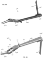
- FIGS. 4A-4E illustrate the second arm 104 in greater detail.
- the second arm 104 can include a distal portion 402 configured to contact a spinal fixation element and/or bone anchor, a pivot arm 404, a proximal handle 406, and a proximal end portion 408 that can include the lock 204. Also shown in these figures is the ratchet bar 410 of the lock 204.
- the proximal handle 406 of the second arm 104 can include a number of different features to facilitate a user grasping and manipulating the handle.
- the proximal handle 406 can include one or more depressions 411 configured to seat a user's fingers.
- the proximal handle 406 of the second arm 104 can include one or more finger loops configured to receive a user's fingers, as shown, for example, in FIGS. 28 , 39 , 42 , and 43 .
- the proximal handle 406 can include grip or comfort-enhancing features, such as a silicone or other material overmolded portion to facilitate grasping.
- the proximal handle 406 can also include one or more protrusions configured to assist user's in maintaining their grip when imparting axial forces to the instrument 100.
- the second arm 104 includes a protrusion 413 formed at a distal position along the handle 406 to prevent a user's hand from slipping off the handle when, e.g., urging the instrument distally to couple with a bone anchor receiver member.
- the pivot arm 404 can extend at an oblique angle relative to longitudinal axes defined by the distal portion 402 and the proximal handle 406.
- the pivot arm 404 can also define a recess 415 between opposed struts 417 that can receive the first arm 102 therethrough during assembly and operation.
- the opposed struts 417 can include bores to receive the pins 202 that pivotably couple the first and second arms 102, 104.
- the distal portion 402 can have a curved profile to accommodate passage of the reducer tube 106 and/or rod-engaging tip 108, as well as to facilitate coupling with a bone anchor receiver member that can have a generally curved shape at the interface between the two components.
- the distal portion 402 can also include an engagement feature 412 formed along a distal portion thereof that can be configured to interface with a complementary feature on a bone anchor receiver member to facilitate coupling between the two components.
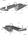
- FIGS. 4C-4E illustrate the distal end of the distal portion 402 in greater detail.
- the engagement feature 412 can be a protrusion 412, such as a ridge extending across a width of the arm, that can be configured to be received within a slot or other recess formed in a proximal outer surface portion of a bone anchor receiver member to facilitate coupling between the components.
- the ridge or other protrusion can extend across an entire width of the arm or, in some embodiments, can extend across only a portion of a width of the arm or include one or more breaks along its length.
- Example bone anchors having such features are described in U.S. Patent No. 7,179,261 .
- engagement feature configurations are possible as well, including reversing the above-described configuration such that a protrusion formed on a bone anchor is received in a recess formed in the distal portion 402. It is also possible to utilize other geometries, e.g., a pin extending from the inner surface of the distal portion 402 that can be received within a bore formed in a receiver member of a bone anchor. An example of a pin disposed in a bore formed in the distal portion 402 can be seen in the embodiment of FIG. 43 .
- the engagement feature 412 can be disposed proximal to a distal-most end of the arm's distal portion 402 and an inner surface of the arm distal to the engagement feature can be configured to facilitate alignment and coupling of the instrument with a bone anchor receiver member.
- an internal surface 419 of the arm can have a shape or profile that is complementary to an outer surface of the bone anchor in order to facilitate coupling even in the event there is some amount of misalignment, whether that be, e.g., lateral or rotational misalignment along an axis of a rod, rotational misalignment along a longitudinal axis of the instrument 100, etc.
- the inner surface 419 can include a tapered profile complementary to an outer surface of opposed arms of a polyaxial bone anchor receiver head.
- the inner surface 419 can include a conical tapering profile that is complementary to the conical tapering profile of a receiver member.
- the profile can be flat without any tapering. Even in such a configuration, the additional extension of the distal portion of the arm beyond the engagement feature 412 can facilitate alignment and coupling between the instrument 100 and a bone anchor receiver member.
- the inner surface 419 can include sidewalls 421 extending outward from the inner surface 419 at lateral ends thereof.
- the sidewalls 421 can similarly include a tapering profile to aid alignment with a receiver member of a bone anchor, e.g., by self-correcting for rotational misalignment about the longitudinal axis of the instrument as the instrument is advanced distally relative to the bone anchor.
- the opposed, inward-facing surfaces of each sidewall 421 can have a planar tapering profile that can be complementary to a planar tapering profile of abutting surfaces on a bone anchor receiver member.
- the various tapered surfaces can accommodate misalignment when coupling the instrument 100 to a bone anchor such that advancement of the instrument over the bone anchor forces the two components into proper alignment just prior to positive engagement of the pivoting arms 102, 104 with the anchor to simplify attachment of the instrument 100 to the anchor.
- the receiver member can include one or more complementary tapering profiles to the tapered surfaces provided on the outer sleeve. Further details on features of the anchor that can be utilized with the instruments disclosed herein can be found in U.S. Patent Nos. 10,039,578 and 10,299,839 , as well as U.S. Provisional Appl. No. 63/157,362, entitled “Multi-Feature Polyaxial Screw” and filed on March 5, 2021 .
- FIG. 5 illustrates the portion of the lock 204 coupled to the second arm 104 in greater detail.
- the lock 204 can include a ratchet bar 410 rotatably coupled to the proximal portion 408 of the second arm 104 by being disposed in a bore formed in the proximal portion of the second arm and secured with screw 302.
- a drag or friction force can be applied to the ratchet bar 410 using a pin 304 disposed in a transversely-oriented bore formed in the proximal portion 408 of the second arm 104.
- the pin 304 can be urged against a portion of the ratchet bar 410 using a coil spring 306 or other biasing element.
- FIGS. 6A-6F illustrate the first arm 102 in greater detail.
- the first arm 102 can include a distal portion 602, a housing 604, a proximal handle 606, and a proximal end 608 that include a catch 610 that forms a complementary portion of the lock 204 and interfaces with the ratchet bar 410.
- the distal portion 602 can be similar to the distal portion 402 of the second arm 104 described above, including an engagement feature 612 and similarly configured surface profiles to facilitate coupling with a bone anchor receiver member.
- proximal handle 606 can be a mirror or similarly configured as the proximal handle 406 of the second arm 104 described above, including the use of features like finger-recesses 611 and a protrusion 613 to assist during application of axial forces to the first arm 102.
- the housing 604 can include a lumen 615 having threads 614 formed along at least a portion of a surface thereof.
- the lumen 615 can define the longitudinal axis A2 of the instrument 100, or at least the longitudinal axis A2 along which the reducer tube 106 and rod-engaging tip 108 translate during reduction maneuvers.
- the threads 614 formed on the surface of the lumen 615 can be continuous and extend around a circumference thereof, i.e., around an entire perimeter of the lumen 615. This can be in contrast to partial-circumference thread forms interrupted by longitudinal slots, etc.
- the lumen 615 of the housing 604 can also include one or more protrusions 616 extending from a surface thereof at a position distal to the threads 614. As explained in more detail below, the one or more protrusions 616 can be received within a recess of the rod-engaging tip 108 to prevent relative rotation between the tip and the first arm 102.
- Other configurations are also possible, however, including, for example, a feature formed along the distal portion 602 rather than in the housing 604, any of a variety of cooperating shapes, protrusions, and recesses that can prevent relative rotation, etc.
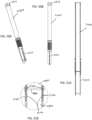
- FIG. 7 illustrates the reducer tube 106 and rod-engaging tip 108 in greater detail.
- the reducer tube 106 is rotatably coupled to the rod-engaging tip 108, i.e., the two components can rotate relative to one another but are prevented from axially translating relative to one another.
- the rod-engaging tip 108 can include opposed extensions 705 formed at a distal end thereof that can be sized and shaped to contact a spinal fixation element, such as a rod, during an axial reduction maneuver.
- the rod-engaging tip 108 can also include a groove 709 or other recess formed in an outer surface thereof and extending at least partially along a length thereof.
- the groove 709 can receive the protrusion 616 formed on the surface of the lumen 615 of the housing 604 in order to prevent relative rotation between the tip 108 and the first arm 102.
- the reducer tube 106 and rod-engaging tip 108 can be rotatably coupled in a manner that permits relative rotation while preventing relative axial translation between the components. This can be accomplished using pins 712 disposed through bores formed in the reducer tube 106 and extending into an interior of the reducer tube. The pins can be received within a groove formed in a proximal end of the rod-engaging tip 108, as described in more detail below.
- the reducer tube 106 can include a threaded outer surface portion 714 configured to interface with the threads 614 formed on the surface of the lumen 615 of the housing 604.
- a depth stop 716 can be formed on the reducer tube 106 at a position proximal to the threads 714. The depth stop 716 can be configured to contact a proximal portion of the housing 604 in order to limit the distal advancement of the reducer tube 106 and rod-engaging tip 108 relative to the first and second arms 102, 104.
- This depth can be configured to allow for the reduction of multiple diameter spinal fixation rods, e.g., 5.5 mm and 6 mm diameter rods, while providing sufficient reduction to allow a set screw or other locking element to engage a receiver member (e.g., threads of a set screw to engage with threads formed on a proximal surface of a receiver member) and prevent excessive reduction that can create tension and inhibit easy decoupling of the instrument from the receiver member after the set screw or other locking element is installed.
- the depth stop can be positioned to provide about 6.5 mm of clearance between a distal end of the rod-engaging tip 108 and the base of a bone anchor receiver member rod slot at maximum axial reduction when the depth stop 716 contacts the housing 604.
- the depth stop 716 can have a variety of forms, including any of a variety of protrusions formed on an outer surface of the reducer tube 106 around part of or an entirety of its circumference. In the illustrated embodiment, the depth stop 716 is a shoulder formed around a circumference (i.e., an entire perimeter) of the reducer tube 106.
- An intermediate portion 704 can extend proximally from the depth stop to a drive feature 718 formed on a proximal end of the reducer tube 106.
- the intermediate portion 704 can have a variety of shapes, diameters, and lengths. In the illustrated embodiment, the intermediate portion 704 has a generally cylindrical shape.
- the drive feature 718 formed at a proximal end of the reducer tube 106 can allow for modular coupling of a driver handle, powered driver, or other torque application implement to the reducer tube 106 in order to effect rotation of the tube and axial reduction of a spinal fixation element.
- the drive feature 718 can also permit access to the lumen 707 therethrough, e.g., as shown in FIG. 11A described below.
- the drive feature 718 can have a variety of forms and sizes.
- the drive feature 718 can include one or more flats to facilitate the application of torque thereto.
- the drive feature 718 is a hex feature having six flat portions disposed around a circumference of the reducer tube 106.
- an outer diameter of the depth stop 716 can be greater than an outer diameter of any other portion of the reducer tube 106 (e.g., greater than the outer diameter of the threaded portion 714 or the drive feature 718). Utilizing a lower profile drive feature 718 can reduce the footprint of the instrument 100 while still allowing a larger driver handle (e.g., a T-handle, powered driver, etc.) to be coupled to the instrument when needed.
- a larger driver handle e.g., a T-handle, powered driver, etc.
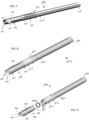
- FIGS. 8-12B illustrate another embodiment of a reducer tube 806 and a rod-engaging tip 808 in greater detail.
- the reducer tube 806 and rod-engaging tip 808 are similar to the embodiments described above, including the use of distal extensions 805 formed on the rod-engaging tip 808, a lumen 807 extending through the two components, and a groove 809 to receive a protrusion formed on the housing 604.
- the rod-engaging tip 808 includes a differently-shaped opening 810 or window formed in a sidewall thereof. In particular, the opening is extended along a longitudinal axis of the tip 808 but compressed in the radial dimension.
- the reducer tube 806 includes similar pins 812 or other protrusions (e.g., integrally-formed protrusions, protrusions of different shape, etc.) that can be used to couple the reducer tube to the rod-engaging tip, as well as threads 814, depth stop 816, intermediate portion 804, and drive feature 818.
- protrusions e.g., integrally-formed protrusions, protrusions of different shape, etc.
- FIGS. 12A and 12B illustrate the rotatable coupling of the reducer tube 806 and rod-engaging tip 808 in greater detail.
- the pins 812 or other protrusions extending into an interior of the reducer tube 806 are visible, as well as the groove 904 formed in the rod-engaging tip 808 where the pins ride to allow for relative rotation while preventing relative translation.
- a thrust washer 902 disposed between a proximal end of the rod-engaging tip 808 and an interior shoulder 1201 (see FIG. 12B ) formed along a distal portion of the reducer tube 806.
- FIGS. 10-11B show the rod-engaging tip 808 and reducer tube 806 in isolation to better illustrate their features.
- FIG. 11B is the detail view of the threads 814 formed on the outer surface of the reducer tube 806.
- Any of a variety of thread forms can be utilized with the instruments of the present disclosure.
- FIG. 10-11B show the rod-engaging tip 808 and reducer tube 806 in isolation to better illustrate their features.
- FIG. 11B is the detail view of the threads 814 formed on the outer surface of the reducer tube 806.
- a thread form that is low profile in order to minimize an outer diameter of the threaded portion 814, which can allow minimization of a size of the housing 604 and resulting instrument 100.
- an outer diameter D1 of the threaded outer surface portion of the tube can be less than or equal to about 45% larger than a diameter D2 of an inner lumen 807 of the tube 806.
- the outer diameter D1 of the threaded outer surface portion of the tube can be less than or equal to about 40%, about 35%, about 30%, about 25%, or about 20% larger than the diameter D2 of the inner lumen 807 of the tube 806.
- the diameter D1 can be about 13 mm and the diameter D2 can be about 9 mm. Utilizing such a configuration can minimize an outer diameter of the threads of the tube and provide a lower profile instrument to access a surgical site through a smaller opening or with less interference for adjacent anatomy or instrumentation.
- thread forms with lower mechanical advantage can also be desirable to provide thread forms with lower mechanical advantage, which can provide better tactile feedback to a user during a reduction maneuver.
- thread forms with one or more starts can be utilized and, in some embodiments, a thread forms with a plurality of starts can be utilized. In the illustrated embodiment, a thread form with three starts 1102 (the third start is not visible) is illustrated, as shown in FIG. 11B .
- FIGS. 13 and 14 illustrate one embodiment of a biplanar reducer instrument 1300 according to the present disclosure that incorporates the first and second arms 102, 104 discussed above with the reducer tube 806 and rod-engaging tip 808. These figures also illustrate in greater detail the placement and operation of the biasing element 206 that can bias the arms 102, 104 toward an open configuration and the lock 204 with drag force mechanism.
- FIGS. 15-26 illustrate a background method of operation of a biplanar forceps reducer instrument according to the present disclosure.
- FIG. 15 illustrates one embodiment of a vertebral body 1502 and a bone anchor or implant 1504 (also shown is a longitudinal axis A3 of the implanted bone anchor).
- FIG. 16 shows the vertebral body 1502 and implant 1504 with a spinal fixation element 1602, e.g., a rod, disposed in a position that is both laterally (e.g., transverse to the longitudinal axis A3 of the implanted bone anchor) and axially (e.g., parallel to the longitudinal axis A3 of the implanted bone anchor) offset relative to the bone anchor.
- FIG. 15 illustrates one embodiment of a vertebral body 1502 and a bone anchor or implant 1504 (also shown is a longitudinal axis A3 of the implanted bone anchor).
- FIG. 16 shows the vertebral body 1502 and implant 1504 with a spinal fixation element
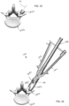
- 16 also shows the introduction of the biplanar forceps reducer instrument 100, in particular a first positioning of the instrument in which a distal portion 402 of the first arm 102 is docked against one side of the bone anchor 1504 and the distal portion 602 of the second arm 104 is used to capture the laterally offset rod 1602.
- FIG. 17 illustrates a lateral reduction step that can be achieved by actuating the first and second arms 102, 104.
- a user can bring proximal handle portions of the arms 102, 104 toward one another to cause the distal portions 402, 602 to pivot toward one another.
- This movement will urge the rod 1602 and the implant 1504 toward one another in a lateral direction (e.g., a direction transverse to the longitudinal axis of the instrument or the implant), ultimately bringing the rod into lateral alignment with the implant along a longitudinal axis, as shown in FIG. 17 .
- a lateral direction e.g., a direction transverse to the longitudinal axis of the instrument or the implant
- Actuation of the arms 102, 104 can also result in the distal portions 402, 602 of both arms being docked to the implant 1504 (e.g., such that engagement features formed thereon interface with complementary features formed on opposed outer surfaces of the implant). Still further, FIG. 17 shows the lock 204 maintaining a relative position of the first and second arms 102, 104 such that a user need not maintain force applied to the arms to pivot them toward one another.
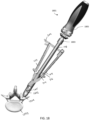
- FIG. 18 illustrates the introduction of a modular driver 1801 that can be coupled to a proximal drive feature 718 of the reducer tube 106 to effect rotation thereof.
- the driver 1801 can include a coupling feature 1803 at a distal end thereof and a proximal handle 1805.
- the coupling feature can be configured to interface with the drive feature 718 in a manner that permits application of torque to the reducer tube 106.
- the coupling feature can be a hex socket 1803 configured to receive the hex drive feature 718 formed on the reducer tube 106.
- an of a variety of alternative drive and coupling feature geometries can be utilized.
- a hand-actuated driver 1801 is illustrated, in other embodiments a differently-configured hand-powered (e.g., a T-handle, etc.) or powered (e.g., electric, pneumatic, hydraulic, etc.) actuator can be utilized.
- a differently-configured hand-powered e.g., a T-handle, etc.
- powered e.g., electric, pneumatic, hydraulic, etc.
- a user can rotate the reducer tube to effect axial translation or reduction of the rod 1602 toward the implant 1504.
- rotation of the reducer tube 106 can cause distal advancement thereof relative to the arms 102, 104 and implant coupled thereto due to the threaded coupling between the reducer tube and the housing 604 of the first arm 102.
- Distal advancement of the reducer tube 106 can cause distal advancement of the rod-engaging tip 108 since these components are coupled in a manner that allows for relative rotation but prevents relative translation.
- the rod-engaging tip 108 can be prevented from rotating relative to the arms 102, 104 by the protrusion formed on the housing 604 of the first arm 104 riding within the longitudinal groove 709 of the rod-engaging tip. As the rod-engaging tip 108 advances distally, the distal-most extensions 705 formed thereon can contact the rod 1602 and urge it distally toward the implant 1504. Lateral movement of the rod 1602 can be prevented by the distal portions 402, 602 of the arms 102, 104.
- FIG. 19 illustrates a fully reduced position of the rod 1602 within a seat of a receiver member of the implant 1504 when the reducer tube 106 has been advanced to a point where the depth stop 716 contacts a proximal end of the housing 604 of the first arm 102.
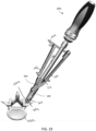
- the driver 1801 can be removed from the instrument 100, as shown in FIG. 20 .
- a set screw 2102 or other locking element can be advanced toward the implant 1504 through the inner lumen 707 of the reducer tube 106.
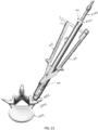
- the set screw 2102 can be coupled to a distal end of an inserter 2104 and the inserter can be utilized to advance the set screw into the lumen 707 from the proximal end of the reducer tube 106, as shown in FIG. 21 .
- the inserter 2104 can be utilized to engage the set screw with threads formed on a proximal portion of the implant receiver member, as shown in FIG. 22 .
- the inserter 2104 can be removed proximally and withdrawn from the inner lumen 707 of the reducer tube 106 and rod-engaging tip 108. Placement of the set screw 2102 can be verified visually through the opening 710 formed in the sidewall of the rod-engaging tip 108, as shown in FIGS. 23A and 23B .
- FIG. 24 illustrates a next background method step in which the instrument 100 is separated from the implant 1504. This can be accomplished by releasing the lock 204 (e.g., pivoting the ratchet bar 410 out of engagement with the catch 610 and allowing the first and second arms 102, 104 to pivot away from one another to separate the distal portions 402, 602 thereof from the implant 1504. The instrument 100 can then be withdrawn proximally, as shown in FIG. 25 . This leaves the final implanted bone anchor 1504 with fully reduced rod 1602 secured by set screw 2102, as shown in FIG. 26 .
- the lock 204 e.g., pivoting the ratchet bar 410 out of engagement with the catch 610 and allowing the first and second arms 102, 104 to pivot away from one another to separate the distal portions 402, 602 thereof from the implant 1504.
- the instrument 100 can then be withdrawn proximally, as shown in FIG. 25 . This leaves the final implanted bone anchor 1504 with fully reduced rod 1602 secured by set
- FIGS. 27A and 27B illustrate alternative embodiments of biplanar forceps reducer instruments.
- FIG. 27A illustrates an embodiment in which a reducer tube 2706 having a shorter intermediate portion 2709 is utilized.
- the reducer tube 2706 can include an intermediate portion 2709 that is short enough in length that the proximal end drive feature of the reducer tube is disposed distal to the lock 204 and/or proximal ends of the arms 102, 104.
- a driver 2701 can be utilized that includes an extended intermediate portion 2707 between its coupling feature 2703 and proximal handle 2705.
- FIG. 27B illustrates another embodiment in which a reducer tube 2706' includes an integrated driver handle 2713 rather than the modular configuration described above.
- the reducer tube driver handle 2713 can still provide access to an inner lumen thereof through its proximal end, such that a set screw inserter 2104 can be utilized to deliver a set screw, as shown in FIG. 27B .
- FIGS. 28-35 illustrate views of one embodiment of a biplanar forceps reducer 2800 according to the present disclosure.
- the exploded view of FIG. 29 shows that the instrument 2800 includes lateral reduction forceps 2902 with internal reduction threads that interface with a hollow axial reducer tube 2904 having external reduction threads formed thereon.
- Opposed distal tips 2906 of the forceps 2902 include implant engagement features that can interface with portions of a bone anchor receiver head, such as opposed sides or features formed on opposed sides, e.g., notches, grooves, holes, etc.
- the forceps 2902 can include a ratchet lock 2908 that is offset from the longitudinal axis of the reducer tube to ensure no interference between these components.
- a rod-engaging reduction tip 2910 can be coupled to a distal end of the reducer tube 2904 in a manner that allows relative rotation of the tip about a longitudinal axis of the tube but prevents axial translation or separation of the components.
- the rod-engaging tip 2910 can be disposed between the opposed lateral reduction forceps 2902 and prevented from rotating relative thereto such that the tip remains properly oriented to engage a rod even as the axial reducer tube is rotated.
- a driver feature 2912 or handle can be formed on a proximal end of the axial reducer tube 2904 to facilitate rotation of the tube to effect axial reduction of a rod disposed between the opposed jaws of the lateral reduction forceps 2902.
- FIG. 30 illustrates the distal end of the axial reducer tube 2904 and the rod-engaging tip 2910.
- the axial reducer tube 2904 and rod-engaging tip 2910 can be hollow to allow for set screw passage while minimizing tube outer diameter. This can contribute to lower instrument profile and improve the ability to use the instrument in tight spaces, e.g., on adjacent closely spaced vertebral levels, etc.
- the distal end of the reducer tube 2904 can include a groove 3002 and the proximal end of the rod-engaging tip 2910 can include opposed wings 3004 with a feature 3006 that snaps into the groove 3002 of the reducer tube to allow free rotation about a longitudinal axis of the tube while preventing axial translation or separation thereof.
- the body of the forceps 2902 can include internal threads 3202 to interface with the external threads of the reducer tube.
- the threads 3202 can include bilateral slots 3204 formed therein to allow the rod-engaging tip 2910 to pass through.
- the opposed wings or arms 004 of the rod-engaging tip can articulate with the distal portion of the lateral reducer forceps jaws to prevent rotation of the rod-engaging tip 2910 as the axial reducer tube is rotated through the threads formed on the forceps body 2902.
- FIGS. 33-38 illustrate a background method of using the instrument 2800 described above.
- the illustrated rod 3302 is positioned both laterally and axially offset from the channel 3304 of the bone anchor 3306 receiver head 3308.
- the reducer forceps 2902 are moved to an open position and the reducer tube 2904 is rotated to withdraw it proximally.
- the reducer is positioned to capture both the rod 3302 and receiver head 3308 between distal forceps arms or jaws.
- the reducer instrument 2800 engages the rod 3302 and receiver head 3308 by positioning a first forceps jaw or arm against the bone anchor receiver head and a second forceps jaw or arm against the rod that is laterally and axially offset from the receiver head.
- FIG. 33 the illustrated rod 3302 is positioned both laterally and axially offset from the channel 3304 of the bone anchor 3306 receiver head 3308.
- the reducer forceps 2902 are moved to an open position and the reducer tube 2904 is rotated to withdraw it proximally.
- the receiver head 3308 can include one or more features (e.g., notches, grooves, indentations, protrusions, etc.) that can interface with complementary features formed on inner surfaces of the distal forceps jaws or arms to facilitate more secure locking of the forceps to the receiver head.
- features e.g., notches, grooves, indentations, protrusions, etc.
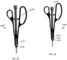
- the rod can be axially reduced into the channel of the receiver head, as shown in FIG. 36 .
- This axial reduction can be maintained by virtue of the threaded connection between the reducer tube and forceps body.
- FIG. 37 illustrates introduction of a set screw 3702 and set screw insertion instrument 3704 through the cannula of the reducer tube 2904.
- the set screw 3702 can be delivered to the receiver head 3308 of the bone anchor and installed to secure capture of the rod 3302 within the channel 3304 of the receiver head.
- FIG. 38 illustrates tightening of the set screw 3702 using the inserter 3704 positioned within the cannula of the reducer tube 2904. Introduced to the bone anchor in this manner, the set screw 3702 can be provisionally and finally tightened to complete spinal fixation construct without the need to remove the biplanar forceps reducer.
- FIG. 39 illustrates another embodiment of a biplanar forceps reducer 3900 that is similar to the reducer 2800 discussed above, including lateral reduction forceps 3902 with internal reduction threads that interface with a hollow axial reducer tube 3904 having external reduction threads formed thereon.
- the reducer 3900 utilizes a different configuration of user-graspable handles/finger loops 3914 from the handles/finger loops 2914 utilized in the reducer 2800.
- Any of a variety of finger loops or other user-graspable handle configurations can be employed.
- Several examples are disclosed in the embodiments described herein, but any combination of grips is possible and contemplated by the present disclosure.
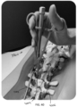
- FIG. 40 illustrates a rod 4002 that is positioned both laterally and dorsally relative to one or more bone anchors 4004 implanted in the vertebrae of a patient's spine 4006.
- the rod 4002 needs to be translated in two planes to be received within the channel formed in the receiver heads of the implanted bone anchors 4004: medially in the coronal plane and anteriorly in the sagittal plane.
- the figure shows the biplanar forceps reducer 3900 disposed to impart lateral and axial reduction to the rod 4002 relative to a bone anchor 4004.
- additional reducer instruments can be coupled to each of the adjacent bone anchors (or all of the bone anchors) and used together to provide the required reduction forces.
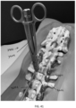
- FIG. 41 illustrates the biplanar forceps reducer 3900 after imparting lateral and axial reduction forces to move the rod 4002 into the channels of the implanted receiver heads of bone anchors 4004.
- the lateral reduction can be maintained by virtue of the locking forceps handles and the axial reduction can be maintained by virtue of the threaded engagement between the reducer tube and the forceps body.
- a user can introduce a set screw through the cannulated reducer tube 3904 and provisionally or finally lock the rod 4002 into position relative to the implanted bone anchor 4004.
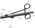
- the instrument 4200 likewise includes opposed distal tips 4206 of the forceps 4202 that can interface with portions of a bone anchor receiver head, a ratchet lock 4208 that is offset from the longitudinal axis of the reducer tube, a rod-engaging reduction tip 4210 coupled to a distal end of the reducer tube 4204 in a manner that allows relative rotation of the tip about a longitudinal axis of the tube but prevents axial translation or separation of the components, and a driver feature 4212 or handle formed on a proximal end of the axial reducer tube 4204 to facilitate rotation of the tube to effect axial reduction of a rod disposed between the opposed jaws of the lateral reduction forceps 4202.
- the reducer 4200 utilizes a different configuration of user-graspable handles/finger loops 4214 from those utilized in the above-described reducers. More particularly, the handles 4214 in the instrument 4200 are offset from the longitudinal axis of the reducer tube 4204, such that they lie in a plane with the ratchet lock 4208. In contrast, the user-graspable handles 2914 and 3914 are aligned with the longitudinal axis of the reducer tube and only the ratchet lock 4208 extends to a position offset from the longitudinal axis of the reducer tube.
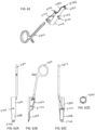
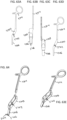
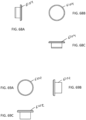
- FIGS. 43A-73B illustrate additional views of embodiments of the biplanar forceps reducer instruments disclosed herein. More particularly, FIGS. 43A-43D illustrate various views of a biplanar forceps reducer 4300 similar to the reducer 4200 described above, including forceps 4302, reducer tube 4304, ratchet lock 4308, reducing tip 4310, and drive feature 4312.
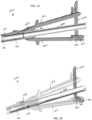
- FIGS. 44A and 44B illustrate cross-sectional views of the reducer 4300 showing interaction of the reducer tube 4304 with the forceps body 4302 and the shoulder 4316 formed on the tube that serves as a depth stop for distal advancement of the tube relative to the forceps body.
- FIG. 45 illustrates the proximal removal of the reducer tube 4304 and reducing tip 4310 from the forceps body 4302.
- FIG. 46 illustrates an exploded view of the two forceps handles that are coupled by pins 4320 to facilitate pivoting movement therebetween.
- the thrust washer 4800 is disposed at a proximal end of the rod-engaging tip 4310 and interfaces at its proximal end with a distal-facing shoulder 5102 formed on an inner surface of the reducer tube 4304.
- FIGS. 49A-49C illustrate various views of a rotation pin 4320 that can be used to couple the opposed arms of the forceps 4302, as shown in FIG. 46 .
- FIGS. 50A and 50B illustrate various view of the reducer tube 4304 and rod-engaging tip 4310.
- FIGS. 51A and 51B illustrate these components in cross-section to show their coupling, as described above.
- FIGS. 52A-52E illustrate various views of the rod-engaging tip 4310 that interfaces with the reducer tube 4304 and forceps 4302 to provide translation without rotation in connection with rotation of the reducer tube.
- FIGS. 53 and 54 illustrate different cross-sectional views of the rod-engaging tip 4310. In particular, these figures highlight the groove 5100 formed at a proximal end of the rod-engaging tip and configured to receive the pins 4700 to couple the tip to the reducer tube 4304 in a manner that allow for relative rotation.
- the longitudinal or axial groove 5208 formed in opposing sides of the outer surface of the tip 4310 that can receive a pin or other protrusion formed on an inner surface of a lumen of the forceps 4302 to maintain a rotational position of the tip 4310 as it translates in response to rotation of the tube 4304.
- FIGS. 55A-55D illustrate various views of the reducer tube 4304, including holes 5502 near a distal end thereof that receive the dowel pins 4700 of FIG. 47 . Also shown is the drive feature 4312, threads 5514 that engage with the forceps 4302, and shelf 5516 that serves as a stop against further distal advancement of the reducer tube 4304 relative to the forceps 4302.
- FIGS. 56A and 56B illustrate different cross-sectional views of the reducing tube 4304.
- FIGS. 57A-57G illustrate various views of the forceps body 4302, including the internal threads 5714 formed thereon and holes 5702 that receive the rotation pins 4320 of FIGS. 49A-49C to join the opposed forceps arms or jaws.
- FIGS. 58A and 58B illustrate cross-sectional views of the forceps body 4302. Also shown in these figures is a hole 5704 that can accommodate a pin 6102 (see FIGS. 61 and 68A-68C ) that extends into the inner lumen of the forceps body 4302.
- This pin can, for example, be received within the groove 5208 formed in the rod-engaging tip 4310 to maintain its rotational position relative to the forceps body 4302 as the reducer tube 4304 is rotated to cause translation of the rod-engaging tip 4310.
- One or more of these holes can be formed in the forceps body 4302 (e.g., two opposing pins 6102 are shown in FIG. 61 ) and the pin can be secured in a number of manners, including use of adhesives, welding, other mechanical fastening, etc.
- a protrusion or other feature can be integrally formed with the body rather than inserting a pin through a hole.
- FIGS. 61 and 67A-67C illustrate a further hole 5706 formed in a distal end of the distal tip 4306 of the forceps.
- This hole can accommodate a pin 6104 (see FIGS. 61 and 67A-67C) that extends radially inward from the distal tip 4306 and can be received in, for example, a hole or bore formed in a receiver head of a bone screw in order to facilitate coupling between the distal tip 4306 of the forceps and the receiver head.
- a pin 6104 see FIGS. 61 and 67A-67C
- One or more of these holes can be formed in the forceps body 4302 and the pin can be secured in a number of manners, including use of adhesives, welding, other mechanical fastening, etc.
- a protrusion or other feature can be integrally formed with the body rather than inserting a pin through a hole.
- different shapes such as a shoulder or ridge, etc., can be utilized.
- FIG. 59 illustrates one embodiment of proximal forceps handles 5900 including rings to accept user fingers and a ratchet lock. As noted above, a variety of different forceps handle shapes, whether including finger rings or not, can be utilized.
- FIGS. 60A-60D , 61, and 62A-62D illustrate various views of the forceps body 4302 and proximal handles/finger rings 4314, which can be integrally formed or joined by any of a variety of techniques, including mechanical coupling with bolts, welding, adhesives, etc.
- FIGS. 63A-63E and 64 illustrate various view of the forceps pivot arm 4303 that couples to the forceps body 4302 of FIGS. 60A-62D to form the opposed forceps jaws or arms.
- FIGS. 65A-67B illustrate various views of portions of the pivot arm 4303 of FIGS. 63A-64 .
- FIGS. 68A-68C illustrate various views of an implant locking pin 6104 that can be received within a bore 5706 of each distal forceps jaw or arm (e.g., as shown in FIGS. 60A-62D and 63A-67B ).
- the locking pins 6104 can be configured to protrude from an inner surface of the forceps jaws and be received within a recess formed in a bone anchor receiver member to aid the forceps in locking to the receiver head.
- FIGS. 69A-69C illustrate various views of an alignment pin 6102 that can be received within a bore 5704 formed in the forceps body, as shown in FIGS. 60A-62D .
- these alignment pins 6102 can extend into longitudinal grooves 5208 formed in the sides of the rod-engaging tip 4310 (as shown in FIGS. 52A 54 to prevent the rod-engaging tip 4310 from rotating relative to the forceps body 4302 as it translates relative thereto when the reducer tube 4304 is rotated through the threads 5714 formed on an inner surface of the forceps body.
- FIGS. 70-73B illustrate various views of proximal handles 7014, 7114, 7214, 7314 that can be used with the forceps reducers disclosed herein, including rings to accept user fingers for actuation and ratchet locks 7008, 7108, 7208, 7308 to maintain lateral reduction.
- the instruments disclosed herein can be constructed from any of a variety of known materials.
- Exemplary materials include those which are suitable for use in surgical applications, including metals such as stainless steel, titanium, nickel, cobalt-chromium, or alloys and combinations thereof, polymers such as PEEK, ceramics, carbon fiber, and so forth.
- the devices and background methods disclosed herein can be used in minimally-invasive surgery and/or open surgery. While the devices and background methods disclosed herein are generally described in the context of surgery on a human patient, it will be appreciated that the background methods and devices disclosed herein can be used in any of a variety of surgical procedures with any human or animal subject, or in non-surgical procedures.
- the devices disclosed herein can be designed to be disposed of after a single use, or they can be designed to be used multiple times. In either case, however, the device can be reconditioned for reuse after at least one use. Reconditioning can include any combination of the steps of disassembly of the device, followed by cleaning or replacement of particular pieces, and subsequent reassembly. In particular, the device can be disassembled, and any number of the particular pieces or parts of the device can be selectively replaced or removed in any combination. Upon cleaning and/or replacement of particular parts, the device can be reassembled for subsequent use either at a reconditioning facility, or by a surgical team immediately prior to a surgical procedure.
- reconditioning of a device can utilize a variety of techniques for disassembly, cleaning/replacement, and reassembly. Use of such techniques, and the resulting reconditioned device, are all within the scope of the present application as defined in the claims.
- the devices described herein can be processed before use in a surgical procedure.
- a new or used instrument can be obtained and, if necessary, cleaned.
- the instrument can then be sterilized.
- the instrument can be placed in a closed and sealed container, such as a plastic or TYVEK bag.
- the container and its contents can then be placed in a field of radiation that can penetrate the container, such as gamma radiation, x-rays, or high-energy electrons.
- the radiation can kill bacteria on the instrument and in the container.
- the sterilized instrument can then be stored in the sterile container.
- the sealed container can keep the instrument sterile until it is opened in the medical facility.
- Other forms of sterilization known in the art are also possible. This can include beta or other forms of radiation, ethylene oxide, steam, or a liquid bath (e.g., cold soak). Certain forms of sterilization may be better suited to use with different portions of the device due to the materials utilized, the presence of electrical components, etc.
Landscapes
- Health & Medical Sciences (AREA)
- Orthopedic Medicine & Surgery (AREA)
- Neurology (AREA)
- Surgery (AREA)
- Life Sciences & Earth Sciences (AREA)
- Medical Informatics (AREA)
- Biomedical Technology (AREA)
- Heart & Thoracic Surgery (AREA)
- Engineering & Computer Science (AREA)
- Molecular Biology (AREA)
- Animal Behavior & Ethology (AREA)
- General Health & Medical Sciences (AREA)
- Public Health (AREA)
- Veterinary Medicine (AREA)
- Nuclear Medicine, Radiotherapy & Molecular Imaging (AREA)
- Surgical Instruments (AREA)
Description
- This disclosure relates generally to surgical instruments and, more particularly, to surgical instruments utilized to move one object relative to another, e.g., move a rod or spinal fixation element relative to an implanted bone anchor or other spinal fixation construct component during spine surgery.
- During spine surgery, such as procedures to correct deformities in the spine, fixation constructs are often assembled to hold the spine in a desired shape. Such constructs often include a plurality of implanted bone anchors along multiple vertebrae and a connecting spinal fixation element, such as a rod, that is received within a head of each of the bone anchors and secured using a set screw. In many cases, the bone anchors are first implanted in the vertebrae, a rod is then positioned relative to the bone anchor heads, and set screws applied to secure the rod relative to each bone anchor.
- It can be challenging to position the rod to be received in the head of each bone anchor. In some cases, a rod can be positioned offset from a bone anchor head both dorsally and medially-laterally such that the rod must be translated in both the sagittal plane and the coronal plane to capture it with the bone anchor head. This challenge can be particularly prevalent in procedures to correct deformities, as longer fixation constructs are often used along with uniplanar bone anchor heads that pivot in only one direction, though similar challenges can be faced when using bone anchor heads that move polyaxially as well.
- Prior approaches to overcoming such challenges involve the use of multiple instruments. For example, a first instrument can be utilized to laterally translate a rod over a bone anchor head, and axial reduction of the rod into the bone anchor head can be performed with a second instrument. Often this is accomplished by attaching a lateral reducing instrument to a first bone anchor to move the rod over one or more bone anchors along a portion of a spinal fixation construct. An axial reducer can then be attached to an adjacent bone anchor and used to translate the rod axially into the bone anchor head.
- Such prior approaches can have drawbacks. For example, use of instruments that can reduce, or translate, a rod in only one plane requires the use of additional instrumentation to complete a procedure. Further, since different reducing instruments are attached to different vertebral levels, load sharing among reducers is not possible. Still further, in some cases reducing instruments must be removed prior to set screw insertion due to interference with set screw insertion devices, or such devices must be loaded in a reducer instrument prior to loading a set screw. Both of these requirements can reduce flexibility and complicate a procedure. Finally, some prior instruments are too bulky to fit alongside adjacent instrumentation or around anatomy, especially when bone anchor heads are close together.
- Accordingly, there is a need for improved instruments for reducing or moving one component, such as a spinal fixation rod, relative to another component, such as a bone anchor, including improved instruments for reducing or moving a component in multiple planes.
US2013/066385 provides an instrument according to the preamble ofclaim 1 andUS2012/253413 provides an example of a further instrument. - Disclosed herein are biplanar forceps reducer instruments that address these and other challenges of prior approaches. The biplanar forceps reducer instruments disclosed herein can engage an implant, such as a bone anchor receiver head, and reduce or move a spinal fixation element, such as a rod, in two planes to move the rod into a channel formed in the receiver head. Further, the biplanar forceps reducer instruments disclosed herein can allow for introduction and tightening of a set screw using an inserter that can pass through a cannulated tube of the reducer. The low profile and biplanar reduction functionality can allow a single type of reducer instrument to couple with each bone anchor along a spinal fixation construct and remain in position until the construct is secured in position.
- In one aspect, a surgical instrument can include a first arm having a proximal end, a distal end, and a housing disposed therebetween, the housing including a threaded lumen defining a longitudinal axis, a second arm having a proximal end and a distal end, the second arm pivotably coupled to the first arm, a tube having a threaded outer surface portion disposed within the threaded lumen, a depth stop formed proximal to the threaded portion, and a drive feature at a proximal end of the tube configured to removably couple with a driver to impart torque to the tube, and a rod-engaging tip rotatably coupled to a distal end of the tube, wherein the first and second arms are configured to translate a spinal fixation element laterally toward the longitudinal axis when pivoted toward one another and the rod-engaging tip is configured to translate the spinal fixation element axially along the longitudinal axis when the tube is rotated relative to the housing.
- Any of a variety of alternative or additional features can be included and are considered within the scope of the present disclosure as defined in the claims. For example, in some embodiments, the depth stop can define a maximum outer diameter of the tube. In certain embodiments, the depth stop can be a shoulder formed around at least a portion of the circumference of the tube.
- In some embodiments, the lumen can include continuous threads formed around a circumference thereof. Further, in certain embodiments an inner lumen of the tube can be accessible from a proximal end of the tube through the drive feature. Moreover, in some embodiments the rod-engaging tip can include an inner lumen coaxially disposed with the inner lumen of the tube.
- In some embodiments, the rod-engaging tip can include an opening formed in a distal portion of a sidewall to facilitate viewing contents of an inner lumen of the rod-engaging tip.
- In certain embodiments, a distal end of at least one of the first and second arms can include a protrusion configured to extend into a recess of a bone anchor receiver member. Further, the protrusion can be a pin disposed in a bore formed in the distal end of at least one of the first and second arms. In some embodiments, the protrusion can be a ridge extending across a width of the arm. The ridge or other protrusion can extend across an entire width of the arm or, in some embodiments, can extend across only a portion of a width of the arm or include one or more breaks along its length. In certain embodiments, the protrusion can be disposed proximal to a distal-most end of the arm and an inner surface of the arm distal to the protrusion can have a conical tapering profile. In some embodiments, the inner surface of the arm can include sidewalls extending outward from the inner surface at lateral ends of the arm, and opposed, inward-facing surfaces of each sidewall can have a planar tapering profile.
- In certain embodiments, the instrument can further include a lock configured to selectively maintain a position of the first and second arms relative to one another. In some embodiments, the lock can be coupled to a proximal portion of one or more of the first and second arms, and a proximal end of the tube can be disposed distal to the lock.
- In further content, useful as background information to the disclosure, a surgical method can include positioning a first arm of a reducer instrument against a bone anchor receiver member, as well as positioning a second arm of the reducer instrument against a spinal fixation element. The method can further include positioning a threaded outer surface portion of a tube of the reducer instrument within a threaded lumen formed in a housing of the first arm of the reducer instrument. The method can also include pivoting the first and second arms of the reducer instrument toward one another to translate the spinal fixation element laterally toward a longitudinal axis defined by the threaded lumen. The method can further include coupling a driver to a drive feature formed at a proximal end of the tube, and rotating the tube of the reducer instrument to translate the spinal fixation element axially along the longitudinal axis until a depth stop formed on the tube proximal to the threaded outer surface portion contacts the housing.
- For example, in some background information the method can further include engaging a lock to maintain a position of the first and second arms relative to one another after pivoting the first and second arms toward one another.
- In certain background information, the method can also include separating the driver from the proximal end of the tube after rotating the tube to translate the spinal fixation element axially. Further, the method can include inserting a set screw through an inner lumen of the tube and coupling the set screw with the receiver member. Still further, the method can include visually inspecting the set screw while coupled to the receiver member using an opening formed in a distal portion of a sidewall of rod-engaging tip coupled to the tube.
- In another background aspect, a surgical instrument can include a first arm having a proximal end, a distal end, and a housing disposed therebetween, the housing including a lumen defining a longitudinal axis, the lumen having continuous threads formed around a circumference thereof. The instrument can further include a second arm having a proximal end and a distal end, the second arm pivotably coupled to the first arm, and a tube having a threaded outer surface portion disposed within the lumen. The instrument can further include a rod-engaging tip rotatably coupled to a distal end of the tube, the rod-engaging tip being constrained against rotation relative to the housing by a protrusion coupled to the housing that is received in a recess of the rod-engaging tip. Further, the first and second arms can be configured to translate a spinal fixation element laterally toward the longitudinal axis when pivoted toward one another and the rod-engaging tip can be configured to translate the spinal fixation element axially along the longitudinal axis when the tube is rotated relative to the housing.
- A number of additional or alternative features can be included. For example, in some embodiments, the threads on the outer surface portion of the tube can have a plurality of starts. In some embodiments, the threads on the outer portion of the tube can have three starts. Further, in certain embodiments an outer diameter of the threaded outer surface portion of the tube can be less than or equal to about 45% larger than a diameter of an inner lumen of the tube. In certain embodiments, an outer diameter of the threaded outer surface portion of the tube can be less than or equal to about 40%, about 35%, about 30%, about 25%, or about 20% larger than a diameter of an inner lumen of the tube. Utilizing such a configuration can minimize an outer diameter of the threads of the tube and provide a lower profile instrument to access a surgical site through a smaller opening or with less interference for adjacent anatomy or instrumentation.
- In another background aspect, a surgical instrument can include opposed arms pivotably coupled to one another, a tube threadably coupled to the opposed arms, and a rod-engaging tip rotatably coupled to the tube. Further, the opposed arms can be configured to laterally translate a spinal fixation element when pivoted toward one another and the rod-engagement tip can be configured to axially translate the spinal fixation element when the tube is rotated relative to the opposed arms and the rod-engagement tip.
- As with the aspects and embodiments described above, a number of additional or alternative features are possible. For example, in some embodiments one of the opposed arms can include a housing having a threaded lumen formed therein. Further, in some embodiments the tube can include external threads formed thereon that interface with the threaded lumen of the body. The external threads formed on the tube can include a plurality of starts. In some embodiments, the external threads formed on the tube can include three starts. Further, in some embodiments an outer diameter of the external threads of the tube can be less than or equal to about 45% larger than a diameter of an inner lumen of the tube. In certain embodiments, an outer diameter of the threaded outer surface portion of the tube can be less than or equal to about 40%, about 35%, about 30%, about 25%, or about 20% larger than a diameter of an inner lumen of the tube. Utilizing such a configuration can minimize an outer diameter of the threads of the tube and provide a lower profile instrument to access a surgical site through a smaller opening or with less interference for adjacent anatomy or instrumentation.
- In certain embodiments, the tube can include a depth stop formed proximal to the external threads. The depth stop can defines a maximum outer diameter of the tube in certain embodiments. The depth stop can have a variety of forms, and can be a shoulder formed around at least a portion of the circumference of the tube in some embodiments.
- In some embodiments, the threaded lumen can include continuous threads formed around a circumference thereof. In certain embodiments the housing can include a protrusion received within a recess of the rod-engaging tip to constrain the rod-engaging tip against rotation relative to the housing.
- In certain embodiments, the opposed arms can include opposed proximally-extending handles for user actuation. In some embodiments, the opposed arms can include a lock to maintain their relative position. The lock can include a ratchet in certain embodiments. In some such embodiments, the ratchet can be offset from a longitudinal axis of the tube. In certain embodiments, the lock can be coupled to a proximal portion of one or more of the opposed arms, and a proximal end of the tube can be disposed distal to the lock.
- In some embodiments, the tube can include a drive feature formed at a proximal end thereof to facilitate rotation of the tube. In certain embodiments, an inner lumen of the tube can be accessible from a proximal end of the tube through the drive feature. In some embodiments, the rod-engaging tip can include an inner lumen that is coaxial with the inner lumen of the tube. In certain embodiments, the rod-engaging tip can include an opening formed in a distal portion of a sidewall to facilitate viewing contents of the inner lumen of the rod-engaging tip.
- In certain embodiments, a distal end of at least one of the opposed arms can include an engagement feature configured to interface with a complementary feature of a bone anchor receiver member. In some embodiments, the engagement feature can include a protrusion configured to extend into a recess of a bone anchor receiver member. For example, the protrusion can be a pin disposed in a bore formed in the distal end of the arm, or a ridge extending across a width of the arm. The ridge or other protrusion can extend across an entire width of the arm or, in some embodiments, can extend across only a portion of a width of the arm or include one or more breaks along its length. In some embodiments, the engagement feature can be disposed proximal to a distal-most end of the arm and an inner surface of the arm distal to the protrusion can have a conical tapering profile. Further, in certain embodiments the inner surface of the arm can include sidewalls extending outward from the inner surface at lateral ends of the arm, and opposed, inward-facing surfaces of each sidewall can have a planar tapering profile.
- In further content, useful as background information to the disclosure, a surgical method can include positioning a first arm of a reducer instrument against a bone anchor receiver member, and positioning a second arm of the reducer instrument against a spinal fixation element. The method can further include pivoting the first and second arms of the reducer instrument toward one another to laterally translate the rod toward the receiver member, and rotating a tube of the reducer instrument to axially translate the spinal fixation element toward the receiver member.
- A number of additional or alternative steps can be included. For example, in some background information, the method can further include inserting a set screw through a lumen formed in the tube and coupling the set screw to the receiver member. Further, the method can include visually inspecting the set screw while coupled to the receiver member using an opening formed in a distal portion of a sidewall of a rod-engaging tip coupled to the tube.
- In certain background information, the method can also include locking a position of the first and second arms relative to one another.
- In some background information, the method can include positioning a threaded outer surface portion of the tube within a threaded lumen formed in a housing coupled to one or more of the first arm and the second arm. In certain embodiments, rotating the tube can be continued until a depth stop formed on the tube proximal to the threaded outer surface portion contacts the housing.
- In some background information, the method can further include coupling a driver to a drive feature formed at a proximal end of the tube prior to rotating the tube to axially translate the spinal fixation element. The method can also include separating the driver from the proximal end of the tube after rotating the tube to axially translate the spinal fixation element.
- In certain background information, the method can also include engaging a lock to maintain a position of the first and second arms relative to one another after pivoting the first and second arms toward one another.
- Any of the features or variations described herein can be applied to any particular aspect or embodiment of the present disclosure in a number of different combinations. The absence of explicit recitation of any particular combination is due solely to avoiding unnecessary length or repetition.
- The aspects and embodiments of the present disclosure can be more fully understood from the following detailed description taken in conjunction with the accompanying drawings, in which:
-
FIG. 1A is a perspective view of one embodiment of a biplanar forceps reducer instrument of the present disclosure; -
FIG. 1B is another perspective view of the instrument ofFIG. 1A ; -
FIG. 2 is a perspective view of opposed forceps arms of the instrument ofFIG. 1A ; -
FIG. 3 is an exploded view of the opposed forceps arms ofFIG. 2 ; -
FIG. 4A is a top perspective view of a first forceps arm of the instrument ofFIG. 1A ; -
FIG. 4B is a bottom perspective view of a first forceps arm ofFIG. 4A ; -
FIG. 4C is a detail perspective view of a distal portion ofFIG. 4B ; -
FIG. 4D is a detail top view of a distal portion ofFIG. 4B ; -
FIG. 4E is a detail longitudinal cross-sectional view of a distal portion ofFIG. 4B ; -
FIG. 5 is a partially-transparent detail view of a proximal portion of the forceps arm ofFIG. 4A ; -
FIG. 6A is a top perspective view of a second forceps arm of the instrument ofFIG. 1A ; -
FIG. 6B is a bottom perspective view of a second forceps arm ofFIG. 6A ; -
FIG. 6C is a front perspective view of a second forceps arm ofFIG. 6A ; -
FIG. 6D is a rear perspective view of a second forceps arm ofFIG. 6A ; -
FIG. 6E is another rear perspective view of a second forceps arm ofFIG. 6A ; -
FIG. 6F is another rear perspective view of a second forceps arm ofFIG. 6A ; -
FIG. 7 is a perspective view of a reducer tube and rod-engaging reduction tip of the instrument ofFIG. 1A ; -
FIG. 8 is a perspective view of another embodiment of a reducer tube and rod-engaging reduction tip according to the present disclosure; -
FIG. 9 is an exploded view of the reducer tube and rod-engaging reduction tip ofFIG. 8 ; -
FIG. 10 is a perspective view of the rod-engaging reduction tip ofFIG. 8 ; -
FIG. 11A is a perspective view of the reducer tube ofFIG. 8 ; -
FIG. 11B is a detail view of a distal portion of the reducer tube ofFIG. 11A ; -
FIG. 12A is a longitudinal cross-sectional view of the reducer tube and rod-engaging reducer tip ofFIG. 8 ; -
FIG. 12B is a detail view of a distal portion of the reducer tube and a proximal portion of the rod-engaging reducer tip ofFIG. 12A ; -
FIG. 13 is a longitudinal cross-sectional view of one embodiment of a biplanar forceps reducer instrument of the present disclosure; -
FIG. 14 is a partially-transparent perspective view of the instrument ofFIG. 13 ; -
FIG. 15 is a perspective view of one embodiment of a bone screw implanted in a vertebra; -
FIG. 16 is a perspective view of the instrument ofFIG. 1 capturing a bone screw and spinal fixation rod; -
FIG. 17 is a perspective view of the instrument ofFIG. 1 laterally reducing a spinal fixation rod; -
FIG. 18 is a perspective view of the instrument ofFIG. 1 axially reducing a spinal fixation rod using a driver; -
FIG. 19 is a perspective view of the instrument ofFIG. 1 after axially reducing a spinal fixation rod; -
FIG. 20 is a perspective view of the instrument ofFIG. 1 after removal of a driver; -
FIG. 21 is a perspective view of a set screw being inserted through the instrument ofFIG. 1 ; -
FIG. 22 is another perspective view of a set screw being inserted through the instrument ofFIG. 1 ; -
FIG. 23A is a perspective view of the instrument ofFIG. 1 after insertion of a set screw; -
FIG. 23B is a detail view of a distal portion ofFIG. 23A ; -
FIG. 24 is a perspective view of the instrument ofFIG. 1 releasing from a bone screw; -
FIG. 25 is a perspective view of the instrument ofFIG. 1 withdrawing from a bone screw; -
FIG. 26 is a perspective view of a bone screw and spinal fixation rod fastened to a vertebra; -
FIG. 27A is a perspective view of one embodiment of a biplanar forceps reducer and driver according to the present disclosure; -
FIG. 27B is a perspective view of one embodiment of a biplanar forceps reducer with integrated driver according to the present disclosure; -
FIG. 28 is a perspective view of one embodiment of a biplanar forceps reducer according to the present disclosure; -
FIG. 29 is an exploded view of the instrument ofFIG. 28 ; -
FIG. 30 is an exploded view of a rod-engaging reducer tip and a distal portion of a reducer tube of the instrument ofFIG. 28 ; -
FIG. 31 is a detail side view of a distal portion of the instrument ofFIG. 28 ; -
FIG. 32 is detail end view of a forceps body of the instrument ofFIG. 28 ; -
FIG. 33 is a perspective view of the instrument ofFIG. 28 approaching a bone screw and spinal fixation rod; -
FIG. 34 is a perspective view of the instrument ofFIG. 28 capturing a bone screw and spinal fixation rod; -
FIG. 35 is a perspective view of the instrument ofFIG. 28 laterally reducing a spinal fixation rod; -
FIG. 36 is a perspective view of the instrument ofFIG. 28 axially reducing a spinal fixation rod; -
FIG. 37 is a perspective view of a set screw being inserted through the instrument ofFIG. 28 ; -
FIG. 38 is another perspective view of a set screw being inserted through the instrument ofFIG. 28 ; -
FIG. 39 is a perspective view of one embodiment of a biplanar forceps reducer according to the present disclosure; -
FIG. 40 is a perspective view of the instrument ofFIG. 39 capturing a bone screw and spinal fixation rod; -
FIG. 41 is a perspective view of the instrument ofFIG. 39 after laterally and axially reducing a spinal fixation rod into a bone screw; -
FIG. 42 is a perspective view of one embodiment of a biplanar forceps reducer according to the present disclosure; -
FIG. 43A is a perspective view of one embodiment of a biplanar forceps reducer according to the present disclosure; -
FIG. 43B is an end view of the instrument ofFIG. 43A ; -
FIG. 43C is a detail view of the instrument ofFIG. 43B ; -
FIG. 43D is a top view of the instrument ofFIG. 43A ; -
FIG. 44A is a longitudinal cross-sectional view of the instrument ofFIG. 43A ; -
FIG. 44B is a detail view of a middle portion ofFIG. 44A ; -
FIG. 45 is a partial-exploded view of the instrument ofFIG. 43A ; -
FIG. 46 is another partial-exploded view of the instrument ofFIG. 43A ; -
FIG. 47A is a perspective view of one embodiment of a pin used to couple a reducer tube and rod-engaging reducer tip according to the present disclosure; -
FIG. 47B is a side view of the pin ofFIG. 47A ; -
FIG. 47C is an end view of the pin ofFIG. 47A ; -
FIG. 48A is an end view of one embodiment of a thrust washer according to the present disclosure; -
FIG. 48B is a side view of the thrust washer ofFIG. 48A ; -
FIG. 48C is a perspective view of the thrust washer ofFIG. 48A ; -
FIG. 49A is an end view of one embodiment of a pin used to couple opposing forceps arms according to the present disclosure; -
FIG. 49B is a side view of the pin ofFIG. 49A ; -
FIG. 49C is a perspective view of the pin ofFIG. 49A ; -
FIG. 50A is a perspective view of a reducer tube and rod-engaging reducer tip of the instrument ofFIG. 43A ; -
FIG. 50B is a side view of a reducer tube and rod-engaging reducer tip of the instrument ofFIG. 43A ; -
FIG. 51A is a longitudinal cross-sectional view of a reducer tube and rod-engaging reducer tip of the instrument ofFIG. 43A ; -
FIG. 51B is a detail view of a middle portion ofFIG. 51A ; -
FIG. 52A is a perspective view of a rod-engaging reducer tip of the instrument ofFIG. 43 A; -
FIG. 52B is a top view of a rod-engaging reducer tip of the instrument ofFIG. 43A ; -
FIG. 52C is a side view a rod-engaging reducer tip of the instrument ofFIG. 43A ; -
FIG. 52D is a first end view of a rod-engaging reducer tip of the instrument ofFIG. 43 A; -
FIG. 52E is a second end view of a rod-engaging reducer tip of the instrument ofFIG. 43 A; -
FIG. 53 is a longitudinal cross-sectional view of a rod-engaging reducer tip of the instrument ofFIG. 43A ; -
FIG. 54 is another longitudinal cross-sectional view of a rod-engaging reducer tip of the instrument ofFIG. 43A ; -
FIG. 55A is a perspective view of a reducer tube of the instrument ofFIG. 43A ; -
FIG. 55B is a side view of a reducer tube of the instrument ofFIG. 43A ; -
FIG. 55C is a first end view of a reducer tube of the instrument ofFIG. 43A ; -
FIG. 55D is a second end view of a reducer tube of the instrument ofFIG. 43A ; -
FIG. 56A is a longitudinal cross-sectional view of a reducer tube of the instrument ofFIG. 43A ; -
FIG. 56B is a detail view of a distal portion ofFIG. 56A ; -
FIG. 57A is a perspective view of a forceps body of the instrument ofFIG. 43A ; -
FIG. 57B is a first end view of a forceps body of the instrument ofFIG. 43A ; -
FIG. 57C is a second end view of a forceps body of the instrument ofFIG. 43A ; -
FIG. 57D is a side view of a forceps body of the instrument ofFIG. 43A ; -
FIG. 57E is top view of a forceps body of the instrument ofFIG. 43A ; -
FIG. 57F is a third end view of a forceps body of the instrument ofFIG. 43A ; -
FIG. 57G is a detail view of a distal portion ofFIG. 57E ; -
FIG. 58A is a longitudinal cross-sectional view of a forceps body of the instrument ofFIG. 43 A; -
FIG. 58B is a detail view of a distal portion ofFIG. 58A ; -
FIG. 59 is a side view of one embodiment of forceps handles according to the present disclosure; -
FIG. 60A is a perspective view of a first forceps arm of the instrument ofFIG. 43A ; -
FIG. 60B is another perspective view of a first forceps arm of the instrument ofFIG. 43 A; -
FIG. 60C is a side view of a first forceps arm of the instrument ofFIG. 43A ; -
FIG. 60D is a top view of a first forceps arm of the instrument ofFIG. 43A ; -
FIG. 61 is an exploded view of a first forceps arm of the instrument ofFIG. 43A ; -
FIG. 62A is a bottom view of a first forceps arm of the instrument ofFIG. 43A ; -
FIG. 62B is another side view of a first forceps arm of the instrument ofFIG. 43A ; -
FIG. 62C is another top view of a first forceps arm of the instrument ofFIG. 43A ; -
FIG. 62D is an end view of a first forceps arm of the instrument ofFIG. 43A ; -
FIG. 63A is a side view of a second forceps arm of the instrument ofFIG. 43A ; -
FIG. 63B is a bottom view of a second forceps arm of the instrument ofFIG. 43A ; -
FIG. 63C is a top view of a second forceps arm of the instrument ofFIG. 43A ; -
FIG. 63D is another side view of a second forceps arm of the instrument ofFIG. 43A ; -
FIG. 63E is a perspective view of a second forceps arm of the instrument ofFIG. 43A ; -
FIG. 64 is an exploded view of a second forceps arm of the instrument ofFIG. 43A ; -
FIG. 65A is a perspective view of a pivot arm of the instrument ofFIG. 43A ; -
FIG. 65B is an end view of a pivot arm of the instrument ofFIG. 43A ; -
FIG. 65C is a top view of a pivot arm of the instrument ofFIG. 43A ; -
FIG. 65D is a side view of a pivot arm of the instrument ofFIG. 43A ; -
FIG. 65E is a second end view of a pivot arm of the instrument ofFIG. 43A ; -
FIG. 66A is a transverse cross-sectional view of a pivot arm of the instrument ofFIG. 43 A; -
FIG. 66B is a detail view of an end ofFIG. 66A ; -
FIG. 67A is a longitudinal cross-sectional view of a pivot arm of the instrument ofFIG. 43 A; -
FIG. 67B is a detail view of a distal portion ofFIG. 66A ; -
FIG. 68A is a side view of a pin used to aid coupling a forceps arm with a bone screw according to the present disclosure; -
FIG. 68B is an end view of the pin ofFIG. 68A ; -
FIG. 68C is a top view of the pin ofFIG. 68A ; -
FIG. 69A is an end view of pin used to prevent rotation of a rod-engaging reducer tip according to the present disclosure; -
FIG. 69B is a side view of the pin ofFIG. 69A ; -
FIG. 69C is a top view of the pin ofFIG. 69A ; -
FIG. 70 is a side view of a forceps handle according to the present disclosure; -
FIG. 71A is an end view of a forceps handle according to the present disclosure; -
FIG. 71B is a side view of a forceps handle ofFIG. 71A ; -
FIG. 71C is a top view of a forceps handle ofFIG. 71A ; -
FIG. 72 is a side view of a forceps handle according to the present disclosure; -
FIG. 73A is an end view of a forceps handle according to the present disclosure; and -
FIG. 73B is a side view of a forceps handle ofFIG. 73A . - The present invention is defined in
claim 1 while preferred embodiments are set forth in the dependent claims. Associated methods are also described herein to aid understanding the invention. - Certain exemplary embodiments will now be described to provide an overall understanding of the principles of the structure, function, manufacture, and use of the devices, systems, and background methods disclosed herein. One or more examples of these embodiments are illustrated in the accompanying drawings. The devices, systems, and background methods specifically described herein and illustrated in the accompanying drawings are non-limiting embodiments. The features illustrated or described in connection with one embodiment may be combined with the features of other embodiments. Such modifications and variations are intended to be included within the scope of the present disclosure as defined in the claims. Additionally, to the extent that linear, circular, or other dimensions are used in the description of the disclosed devices and background methods, such dimensions are not intended to limit the types of shapes that can be used in conjunction with such devices and background methods. Equivalents to such dimensions can be determined for different geometric shapes, etc. Further, like-numbered components of the embodiments can generally have similar features. Still further, sizes and shapes of the devices, and the components thereof, can depend at least on the anatomy of the subject in which the devices will be used, the size and shape of objects with which the devices will be used, and the background methods and procedures in which the devices will be used.
- Disclosed herein are biplanar forceps reducer instruments and background methods of use that can facilitate engaging an implant, such as a bone anchor receiver head, and reducing or moving a spinal fixation element, such as a rod, in two planes to move the rod into a channel formed in the receiver head. Further, the biplanar forceps reducer instruments disclosed herein can allow for introduction and tightening of a set screw using an inserter that can pass through a cannulated tube of the reducer. The low profile and biplanar reduction functionality can allow a single type of reducer instrument to couple with each bone anchor along a spinal fixation construct and remain in position until the construct is secured in position.
-
FIGS. 1A and 1B illustrate one embodiment of a biplanarforceps reducer instrument 100 according to the present disclosure. Theinstrument 100 includes afirst arm 102 and asecond arm 104 that are pivotably coupled to one another, as well as areducer tube 106 threadably coupled to the opposed first and second arms and a rod-engagingtip 108 that is rotatably coupled to the reducer tube. As explained in more detail below, theinstrument 100 operates by using the opposed first andsecond arms instrument 100 can reduce, or translate, the rod in multiple dimensions, e.g., laterally and axially. By way of example, a user can squeeze the proximal portions of the first andsecond arms tube 106 can be rotated, which can result in distal translation of the rod-engagingtip 108 rotatably coupled thereto. The rod-engagingtip 108 can contact the rod and reduce or translate it distally into, e.g., a rod-receiving seat of the bone anchor. Finally, a rod locking element, such as a set screw, can be introduced to the bone anchor through a lumen formed in thereducer tube 106 and rod-engagingtip 108. -
FIG. 2 illustrates the opposed first andsecond arms FIG. 3 shows an exploded view of the assembly. The first andsecond arms pins 202 that allow the arms to pivot relative to one another about an axis A1 that is transverse to a longitudinal axis A2 of the instrument. The opposed outer handles of the instrument can also include alock 204 configured to maintain a relative position of the handles or arms, and abiasing element 206 that can be configured to bias the arms in a desired direction. For example, in the illustrated embodiment a portion of thelock 204 can be coupled to a proximal end of thesecond arm 104 using ascrew 302. Aleaf spring 206 can be utilized as a biasing element and secured to thefirst arm 102 usingscrews 308. Theleaf spring 206 can contact a portion of thesecond arm 104 to urge the first and second arms into an open configuration relative to one another.FIG. 3 also illustrates a mechanism that can be utilized to provide friction and maintain a position of a portion of thelock 204 until, e.g., positively moved by a user. The mechanism can include apin 304 disposed in a bore formed in thesecond arm 104 such that one end of the pin is in contact with a portion of thelock 204. Acoil spring 306 or other biasing element can urge thepin 304 against the portion of thelock 204 to provide a friction or drag force against movement of the lock relative to thesecond arm 104. This mechanism is illustrated in greater detail inFIG. 5 . -
FIGS. 4A-4E illustrate thesecond arm 104 in greater detail. Thesecond arm 104 can include adistal portion 402 configured to contact a spinal fixation element and/or bone anchor, apivot arm 404, aproximal handle 406, and aproximal end portion 408 that can include thelock 204. Also shown in these figures is theratchet bar 410 of thelock 204. - The
proximal handle 406 of thesecond arm 104 can include a number of different features to facilitate a user grasping and manipulating the handle. For example, theproximal handle 406 can include one ormore depressions 411 configured to seat a user's fingers. In some embodiments, theproximal handle 406 of thesecond arm 104 can include one or more finger loops configured to receive a user's fingers, as shown, for example, inFIGS. 28 ,39 ,42 , and43 . In still other embodiments, theproximal handle 406 can include grip or comfort-enhancing features, such as a silicone or other material overmolded portion to facilitate grasping. In some embodiments, theproximal handle 406 can also include one or more protrusions configured to assist user's in maintaining their grip when imparting axial forces to theinstrument 100. For example, thesecond arm 104 includes aprotrusion 413 formed at a distal position along thehandle 406 to prevent a user's hand from slipping off the handle when, e.g., urging the instrument distally to couple with a bone anchor receiver member. - The
pivot arm 404 can extend at an oblique angle relative to longitudinal axes defined by thedistal portion 402 and theproximal handle 406. Thepivot arm 404 can also define arecess 415 betweenopposed struts 417 that can receive thefirst arm 102 therethrough during assembly and operation. The opposed struts 417 can include bores to receive thepins 202 that pivotably couple the first andsecond arms - The
distal portion 402 can have a curved profile to accommodate passage of thereducer tube 106 and/or rod-engagingtip 108, as well as to facilitate coupling with a bone anchor receiver member that can have a generally curved shape at the interface between the two components. Thedistal portion 402 can also include anengagement feature 412 formed along a distal portion thereof that can be configured to interface with a complementary feature on a bone anchor receiver member to facilitate coupling between the two components. -
FIGS. 4C-4E illustrate the distal end of thedistal portion 402 in greater detail. As shown in the figures, theengagement feature 412 can be aprotrusion 412, such as a ridge extending across a width of the arm, that can be configured to be received within a slot or other recess formed in a proximal outer surface portion of a bone anchor receiver member to facilitate coupling between the components. The ridge or other protrusion can extend across an entire width of the arm or, in some embodiments, can extend across only a portion of a width of the arm or include one or more breaks along its length. Example bone anchors having such features are described inU.S. Patent No. 7,179,261 . Other engagement feature configurations are possible as well, including reversing the above-described configuration such that a protrusion formed on a bone anchor is received in a recess formed in thedistal portion 402. It is also possible to utilize other geometries, e.g., a pin extending from the inner surface of thedistal portion 402 that can be received within a bore formed in a receiver member of a bone anchor. An example of a pin disposed in a bore formed in thedistal portion 402 can be seen in the embodiment ofFIG. 43 . - In some embodiments, the
engagement feature 412 can be disposed proximal to a distal-most end of the arm'sdistal portion 402 and an inner surface of the arm distal to the engagement feature can be configured to facilitate alignment and coupling of the instrument with a bone anchor receiver member. For example, aninternal surface 419 of the arm can have a shape or profile that is complementary to an outer surface of the bone anchor in order to facilitate coupling even in the event there is some amount of misalignment, whether that be, e.g., lateral or rotational misalignment along an axis of a rod, rotational misalignment along a longitudinal axis of theinstrument 100, etc. In some embodiments, for example, theinner surface 419 can include a tapered profile complementary to an outer surface of opposed arms of a polyaxial bone anchor receiver head. In some instances, theinner surface 419 can include a conical tapering profile that is complementary to the conical tapering profile of a receiver member. Such an arrangement can allow for some pivoting misalignment between the receiver head and theinstrument 100 that can be corrected as the instrument is advanced distally relative to the receiver head. In other embodiments, however, the profile can be flat without any tapering. Even in such a configuration, the additional extension of the distal portion of the arm beyond theengagement feature 412 can facilitate alignment and coupling between theinstrument 100 and a bone anchor receiver member. - Further, the
inner surface 419 can includesidewalls 421 extending outward from theinner surface 419 at lateral ends thereof. Thesidewalls 421 can similarly include a tapering profile to aid alignment with a receiver member of a bone anchor, e.g., by self-correcting for rotational misalignment about the longitudinal axis of the instrument as the instrument is advanced distally relative to the bone anchor. In some embodiments, the opposed, inward-facing surfaces of eachsidewall 421 can have a planar tapering profile that can be complementary to a planar tapering profile of abutting surfaces on a bone anchor receiver member. The various tapered surfaces can accommodate misalignment when coupling theinstrument 100 to a bone anchor such that advancement of the instrument over the bone anchor forces the two components into proper alignment just prior to positive engagement of the pivotingarms instrument 100 to the anchor. As noted, the receiver member can include one or more complementary tapering profiles to the tapered surfaces provided on the outer sleeve. Further details on features of the anchor that can be utilized with the instruments disclosed herein can be found inU.S. Patent Nos. 10,039,578 10,299,839 U.S. Provisional Appl. No. 63/157,362, entitled "Multi-Feature Polyaxial Screw" and filed on March 5, 2021 -
FIG. 5 illustrates the portion of thelock 204 coupled to thesecond arm 104 in greater detail. As noted above, thelock 204 can include aratchet bar 410 rotatably coupled to theproximal portion 408 of thesecond arm 104 by being disposed in a bore formed in the proximal portion of the second arm and secured withscrew 302. In addition, a drag or friction force can be applied to theratchet bar 410 using apin 304 disposed in a transversely-oriented bore formed in theproximal portion 408 of thesecond arm 104. Thepin 304 can be urged against a portion of theratchet bar 410 using acoil spring 306 or other biasing element. -
FIGS. 6A-6F illustrate thefirst arm 102 in greater detail. Thefirst arm 102 can include adistal portion 602, ahousing 604, aproximal handle 606, and aproximal end 608 that include acatch 610 that forms a complementary portion of thelock 204 and interfaces with theratchet bar 410. Thedistal portion 602 can be similar to thedistal portion 402 of thesecond arm 104 described above, including anengagement feature 612 and similarly configured surface profiles to facilitate coupling with a bone anchor receiver member. Similarly, theproximal handle 606 can be a mirror or similarly configured as theproximal handle 406 of thesecond arm 104 described above, including the use of features like finger-recesses 611 and aprotrusion 613 to assist during application of axial forces to thefirst arm 102. - The
housing 604 can include alumen 615 havingthreads 614 formed along at least a portion of a surface thereof. Thelumen 615 can define the longitudinal axis A2 of theinstrument 100, or at least the longitudinal axis A2 along which thereducer tube 106 and rod-engagingtip 108 translate during reduction maneuvers. Thethreads 614 formed on the surface of thelumen 615 can be continuous and extend around a circumference thereof, i.e., around an entire perimeter of thelumen 615. This can be in contrast to partial-circumference thread forms interrupted by longitudinal slots, etc. In some embodiments, however, such a configuration could be utilized in connection with a biplanar forceps reducer according to the present disclosure, e.g., to prevent rotation of a rod-engaging tip without using protrusions formed on thehousing 604. More details on such a configuration and other features can be found inU.S. Patent No. 8,647,347 . - The
lumen 615 of thehousing 604 can also include one ormore protrusions 616 extending from a surface thereof at a position distal to thethreads 614. As explained in more detail below, the one ormore protrusions 616 can be received within a recess of the rod-engagingtip 108 to prevent relative rotation between the tip and thefirst arm 102. Other configurations are also possible, however, including, for example, a feature formed along thedistal portion 602 rather than in thehousing 604, any of a variety of cooperating shapes, protrusions, and recesses that can prevent relative rotation, etc. -
FIG. 7 illustrates thereducer tube 106 and rod-engagingtip 108 in greater detail. Thereducer tube 106 is rotatably coupled to the rod-engagingtip 108, i.e., the two components can rotate relative to one another but are prevented from axially translating relative to one another. The rod-engagingtip 108 can includeopposed extensions 705 formed at a distal end thereof that can be sized and shaped to contact a spinal fixation element, such as a rod, during an axial reduction maneuver. Theextensions 705 can also be configured to extend into a U-shaped gaps formed between opposed arms of a bone anchor receiver member, such that the rod-engagingtip 108 can axially reduce a rod into the receiver member without interfering with delivery of a set screw or other locking element, as described below. Also to facilitate delivery of a set screw or other locking element, the rod-engagingtip 108 andreducer tube 106 can define aninner lumen 707, and the portions thereof extending through eachcomponent - The rod-engaging
tip 108 can also include one ormore openings 710 formed in a sidewall to facilitate viewing into thelumen 707. This can be useful to facilitate visualizing placement of a set screw or locking element delivered through thelumen 707, as described in more detail below. - The rod-engaging
tip 108 can also include agroove 709 or other recess formed in an outer surface thereof and extending at least partially along a length thereof. Thegroove 709 can receive theprotrusion 616 formed on the surface of thelumen 615 of thehousing 604 in order to prevent relative rotation between thetip 108 and thefirst arm 102. - As noted above, the
reducer tube 106 and rod-engagingtip 108 can be rotatably coupled in a manner that permits relative rotation while preventing relative axial translation between the components. This can be accomplished usingpins 712 disposed through bores formed in thereducer tube 106 and extending into an interior of the reducer tube. The pins can be received within a groove formed in a proximal end of the rod-engagingtip 108, as described in more detail below. - The
reducer tube 106 can include a threadedouter surface portion 714 configured to interface with thethreads 614 formed on the surface of thelumen 615 of thehousing 604. Adepth stop 716 can be formed on thereducer tube 106 at a position proximal to thethreads 714. Thedepth stop 716 can be configured to contact a proximal portion of thehousing 604 in order to limit the distal advancement of thereducer tube 106 and rod-engagingtip 108 relative to the first andsecond arms tip 108 and the base of a bone anchor receiver member rod slot at maximum axial reduction when the depth stop 716 contacts thehousing 604. Such a configuration can allow using the device with both 5.5 mm and 6 mm rods with the benefits noted above. Thedepth stop 716 can have a variety of forms, including any of a variety of protrusions formed on an outer surface of thereducer tube 106 around part of or an entirety of its circumference. In the illustrated embodiment, thedepth stop 716 is a shoulder formed around a circumference (i.e., an entire perimeter) of thereducer tube 106. - An
intermediate portion 704 can extend proximally from the depth stop to adrive feature 718 formed on a proximal end of thereducer tube 106. Theintermediate portion 704 can have a variety of shapes, diameters, and lengths. In the illustrated embodiment, theintermediate portion 704 has a generally cylindrical shape. Thedrive feature 718 formed at a proximal end of thereducer tube 106 can allow for modular coupling of a driver handle, powered driver, or other torque application implement to thereducer tube 106 in order to effect rotation of the tube and axial reduction of a spinal fixation element. Thedrive feature 718 can also permit access to thelumen 707 therethrough, e.g., as shown inFIG. 11A described below. Thedrive feature 718 can have a variety of forms and sizes. In some embodiments, thedrive feature 718 can include one or more flats to facilitate the application of torque thereto. In the illustrated embodiment, thedrive feature 718 is a hex feature having six flat portions disposed around a circumference of thereducer tube 106. Further, in the illustrated embodiment an outer diameter of thedepth stop 716 can be greater than an outer diameter of any other portion of the reducer tube 106 (e.g., greater than the outer diameter of the threadedportion 714 or the drive feature 718). Utilizing a lowerprofile drive feature 718 can reduce the footprint of theinstrument 100 while still allowing a larger driver handle (e.g., a T-handle, powered driver, etc.) to be coupled to the instrument when needed. -
FIGS. 8-12B illustrate another embodiment of areducer tube 806 and a rod-engagingtip 808 in greater detail. Thereducer tube 806 and rod-engagingtip 808 are similar to the embodiments described above, including the use ofdistal extensions 805 formed on the rod-engagingtip 808, alumen 807 extending through the two components, and agroove 809 to receive a protrusion formed on thehousing 604. The rod-engagingtip 808 includes a differently-shapedopening 810 or window formed in a sidewall thereof. In particular, the opening is extended along a longitudinal axis of thetip 808 but compressed in the radial dimension. Thereducer tube 806 includessimilar pins 812 or other protrusions (e.g., integrally-formed protrusions, protrusions of different shape, etc.) that can be used to couple the reducer tube to the rod-engaging tip, as well asthreads 814,depth stop 816,intermediate portion 804, and drivefeature 818. - The exploded view of
FIG. 9 and the cross-sectional views ofFIGS. 12A and 12B illustrate the rotatable coupling of thereducer tube 806 and rod-engagingtip 808 in greater detail. For example, thepins 812 or other protrusions extending into an interior of thereducer tube 806 are visible, as well as thegroove 904 formed in the rod-engagingtip 808 where the pins ride to allow for relative rotation while preventing relative translation. Also shown is athrust washer 902 disposed between a proximal end of the rod-engagingtip 808 and an interior shoulder 1201 (seeFIG. 12B ) formed along a distal portion of thereducer tube 806. -
FIGS. 10-11B show the rod-engagingtip 808 andreducer tube 806 in isolation to better illustrate their features. Of note inFIG. 11B is the detail view of thethreads 814 formed on the outer surface of thereducer tube 806. Any of a variety of thread forms can be utilized with the instruments of the present disclosure. In some embodiments, it can be desirable to utilize a thread form that is low profile in order to minimize an outer diameter of the threadedportion 814, which can allow minimization of a size of thehousing 604 and resultinginstrument 100. For example and with reference to the detail cross-sectional view ofFIG. 12B , in some embodiments an outer diameter D1 of the threaded outer surface portion of the tube can be less than or equal to about 45% larger than a diameter D2 of aninner lumen 807 of thetube 806. In certain embodiments, the outer diameter D1 of the threaded outer surface portion of the tube can be less than or equal to about 40%, about 35%, about 30%, about 25%, or about 20% larger than the diameter D2 of theinner lumen 807 of thetube 806. For example, in one embodiment the diameter D1 can be about 13 mm and the diameter D2 can be about 9 mm. Utilizing such a configuration can minimize an outer diameter of the threads of the tube and provide a lower profile instrument to access a surgical site through a smaller opening or with less interference for adjacent anatomy or instrumentation. - In some embodiments it can also be desirable to provide thread forms with lower mechanical advantage, which can provide better tactile feedback to a user during a reduction maneuver. In some embodiments, thread forms with one or more starts can be utilized and, in some embodiments, a thread forms with a plurality of starts can be utilized. In the illustrated embodiment, a thread form with three starts 1102 (the third start is not visible) is illustrated, as shown in
FIG. 11B . -
FIGS. 13 and 14 illustrate one embodiment of abiplanar reducer instrument 1300 according to the present disclosure that incorporates the first andsecond arms reducer tube 806 and rod-engagingtip 808. These figures also illustrate in greater detail the placement and operation of the biasingelement 206 that can bias thearms lock 204 with drag force mechanism. -
FIGS. 15-26 illustrate a background method of operation of a biplanar forceps reducer instrument according to the present disclosure.FIG. 15 illustrates one embodiment of avertebral body 1502 and a bone anchor or implant 1504 (also shown is a longitudinal axis A3 of the implanted bone anchor).FIG. 16 shows thevertebral body 1502 andimplant 1504 with aspinal fixation element 1602, e.g., a rod, disposed in a position that is both laterally (e.g., transverse to the longitudinal axis A3 of the implanted bone anchor) and axially (e.g., parallel to the longitudinal axis A3 of the implanted bone anchor) offset relative to the bone anchor.FIG. 16 also shows the introduction of the biplanarforceps reducer instrument 100, in particular a first positioning of the instrument in which adistal portion 402 of thefirst arm 102 is docked against one side of thebone anchor 1504 and thedistal portion 602 of thesecond arm 104 is used to capture the laterally offsetrod 1602. -
FIG. 17 illustrates a lateral reduction step that can be achieved by actuating the first andsecond arms arms distal portions rod 1602 and theimplant 1504 toward one another in a lateral direction (e.g., a direction transverse to the longitudinal axis of the instrument or the implant), ultimately bringing the rod into lateral alignment with the implant along a longitudinal axis, as shown inFIG. 17 . Actuation of thearms distal portions FIG. 17 shows thelock 204 maintaining a relative position of the first andsecond arms -
FIG. 18 illustrates the introduction of amodular driver 1801 that can be coupled to aproximal drive feature 718 of thereducer tube 106 to effect rotation thereof. Thedriver 1801 can include acoupling feature 1803 at a distal end thereof and aproximal handle 1805. The coupling feature can be configured to interface with thedrive feature 718 in a manner that permits application of torque to thereducer tube 106. In the illustrated embodiment, the coupling feature can be ahex socket 1803 configured to receive thehex drive feature 718 formed on thereducer tube 106. As noted above, an of a variety of alternative drive and coupling feature geometries can be utilized. Further, while a hand-actuateddriver 1801 is illustrated, in other embodiments a differently-configured hand-powered (e.g., a T-handle, etc.) or powered (e.g., electric, pneumatic, hydraulic, etc.) actuator can be utilized. - Once the
driver 1801 is assembled to thereducer tube 106, a user can rotate the reducer tube to effect axial translation or reduction of therod 1602 toward theimplant 1504. In particular, and as described above, rotation of thereducer tube 106 can cause distal advancement thereof relative to thearms housing 604 of thefirst arm 102. Distal advancement of thereducer tube 106 can cause distal advancement of the rod-engagingtip 108 since these components are coupled in a manner that allows for relative rotation but prevents relative translation. The rod-engagingtip 108 can be prevented from rotating relative to thearms housing 604 of thefirst arm 104 riding within thelongitudinal groove 709 of the rod-engaging tip. As the rod-engagingtip 108 advances distally, thedistal-most extensions 705 formed thereon can contact therod 1602 and urge it distally toward theimplant 1504. Lateral movement of therod 1602 can be prevented by thedistal portions arms -
FIG. 19 illustrates a fully reduced position of therod 1602 within a seat of a receiver member of theimplant 1504 when thereducer tube 106 has been advanced to a point where the depth stop 716 contacts a proximal end of thehousing 604 of thefirst arm 102. Following reduction, thedriver 1801 can be removed from theinstrument 100, as shown inFIG. 20 . - With the
modular driver 1801 separated from thereducer tube 106, aset screw 2102 or other locking element can be advanced toward theimplant 1504 through theinner lumen 707 of thereducer tube 106. In particular, theset screw 2102 can be coupled to a distal end of aninserter 2104 and the inserter can be utilized to advance the set screw into thelumen 707 from the proximal end of thereducer tube 106, as shown inFIG. 21 . Once theset screw 2102 reaches theimplant 1504, theinserter 2104 can be utilized to engage the set screw with threads formed on a proximal portion of the implant receiver member, as shown inFIG. 22 . As noted above, thedepth stop 716 and configuration of theinstrument 100 can be such that it does not achieve a true final position of the rod 1602 (i.e., where the rod is bottomed out against a distal portion of a rod seat of the receiver member), but instead reduces the rod far enough to allow a set screw to engage threads in the receiver member. This can allow final reduction and tightening of the rod to be performed using theset screw 2102 andinserter 2104. This will also allow for easier separation of theinstrument 100 by reducing tension in the coupling with theimplant 1504 androd 1602. - Once the
inserter 2104 is utilized to tighten theset screw 2102 to a desired degree, theinserter 2104 can be removed proximally and withdrawn from theinner lumen 707 of thereducer tube 106 and rod-engagingtip 108. Placement of theset screw 2102 can be verified visually through theopening 710 formed in the sidewall of the rod-engagingtip 108, as shown inFIGS. 23A and 23B . -
FIG. 24 illustrates a next background method step in which theinstrument 100 is separated from theimplant 1504. This can be accomplished by releasing the lock 204 (e.g., pivoting theratchet bar 410 out of engagement with thecatch 610 and allowing the first andsecond arms distal portions implant 1504. Theinstrument 100 can then be withdrawn proximally, as shown inFIG. 25 . This leaves the final implantedbone anchor 1504 with fully reducedrod 1602 secured byset screw 2102, as shown inFIG. 26 . -
FIGS. 27A and27B illustrate alternative embodiments of biplanar forceps reducer instruments.FIG. 27A , for example, illustrates an embodiment in which areducer tube 2706 having a shorterintermediate portion 2709 is utilized. In particular, thereducer tube 2706 can include anintermediate portion 2709 that is short enough in length that the proximal end drive feature of the reducer tube is disposed distal to thelock 204 and/or proximal ends of thearms arms driver 2701 can be utilized that includes an extendedintermediate portion 2707 between itscoupling feature 2703 andproximal handle 2705. -
FIG. 27B illustrates another embodiment in which a reducer tube 2706' includes an integrateddriver handle 2713 rather than the modular configuration described above. In such an embodiment, the reducertube driver handle 2713 can still provide access to an inner lumen thereof through its proximal end, such that aset screw inserter 2104 can be utilized to deliver a set screw, as shown inFIG. 27B . - Still other alternative embodiments are also contemplated and provided in the present disclosure. For example,
FIGS. 28-35 illustrate views of one embodiment of abiplanar forceps reducer 2800 according to the present disclosure. The exploded view ofFIG. 29 shows that theinstrument 2800 includeslateral reduction forceps 2902 with internal reduction threads that interface with a hollowaxial reducer tube 2904 having external reduction threads formed thereon. Opposeddistal tips 2906 of theforceps 2902 include implant engagement features that can interface with portions of a bone anchor receiver head, such as opposed sides or features formed on opposed sides, e.g., notches, grooves, holes, etc. Theforceps 2902 can include aratchet lock 2908 that is offset from the longitudinal axis of the reducer tube to ensure no interference between these components. A rod-engagingreduction tip 2910 can be coupled to a distal end of thereducer tube 2904 in a manner that allows relative rotation of the tip about a longitudinal axis of the tube but prevents axial translation or separation of the components. The rod-engagingtip 2910 can be disposed between the opposedlateral reduction forceps 2902 and prevented from rotating relative thereto such that the tip remains properly oriented to engage a rod even as the axial reducer tube is rotated. Finally, adriver feature 2912 or handle can be formed on a proximal end of theaxial reducer tube 2904 to facilitate rotation of the tube to effect axial reduction of a rod disposed between the opposed jaws of thelateral reduction forceps 2902. -
FIG. 30 illustrates the distal end of theaxial reducer tube 2904 and the rod-engagingtip 2910. Theaxial reducer tube 2904 and rod-engagingtip 2910 can be hollow to allow for set screw passage while minimizing tube outer diameter. This can contribute to lower instrument profile and improve the ability to use the instrument in tight spaces, e.g., on adjacent closely spaced vertebral levels, etc. The distal end of thereducer tube 2904 can include agroove 3002 and the proximal end of the rod-engagingtip 2910 can includeopposed wings 3004 with afeature 3006 that snaps into thegroove 3002 of the reducer tube to allow free rotation about a longitudinal axis of the tube while preventing axial translation or separation thereof. - As shown in
FIGS. 31 and 32 , the body of theforceps 2902 can includeinternal threads 3202 to interface with the external threads of the reducer tube. Thethreads 3202 can includebilateral slots 3204 formed therein to allow the rod-engagingtip 2910 to pass through. Further, the opposed wings or arms 004 of the rod-engaging tip can articulate with the distal portion of the lateral reducer forceps jaws to prevent rotation of the rod-engagingtip 2910 as the axial reducer tube is rotated through the threads formed on theforceps body 2902. -
FIGS. 33-38 illustrate a background method of using theinstrument 2800 described above. InFIG. 33 , the illustratedrod 3302 is positioned both laterally and axially offset from thechannel 3304 of thebone anchor 3306receiver head 3308. Thereducer forceps 2902 are moved to an open position and thereducer tube 2904 is rotated to withdraw it proximally. The reducer is positioned to capture both therod 3302 andreceiver head 3308 between distal forceps arms or jaws. InFIG. 34 , thereducer instrument 2800 engages therod 3302 andreceiver head 3308 by positioning a first forceps jaw or arm against the bone anchor receiver head and a second forceps jaw or arm against the rod that is laterally and axially offset from the receiver head.FIG. 35 shows the lateral rod translation or reduction accomplished by bringing the forceps handles toward one another and causing the distal forceps jaws or arms to move toward one another. Theratchet lock 2908 of the forceps can maintain the lateral reduction and allow for step-wise, incremental reduction engaging sequential teeth of the ratchet lock. Further, closing the forceps jaws or arms toward one another can lock the forceps to the boneanchor receiver head 3308 by bringing the second forceps jaw or arm into contact with the receiver head. As noted above, thereceiver head 3308 can include one or more features (e.g., notches, grooves, indentations, protrusions, etc.) that can interface with complementary features formed on inner surfaces of the distal forceps jaws or arms to facilitate more secure locking of the forceps to the receiver head. - With lateral reduction complete, the rod can be axially reduced into the channel of the receiver head, as shown in
FIG. 36 . This is accomplished by rotating thereducer tube 2904 using the drive feature formed at its proximal end. Rotation of thereducer tube 2904 through the threads formed on the forceps body causes translation of the rod-engagingtip 2910 along the distal forceps arms or jaws. The rod-engaging tip translates distally and forces therod 3302 in the same direction toward thechannel 3304 of thereceiver head 3308. This axial reduction can be maintained by virtue of the threaded connection between the reducer tube and forceps body. -
FIG. 37 illustrates introduction of aset screw 3702 and setscrew insertion instrument 3704 through the cannula of thereducer tube 2904. Using this cannula access, theset screw 3702 can be delivered to thereceiver head 3308 of the bone anchor and installed to secure capture of therod 3302 within thechannel 3304 of the receiver head.FIG. 38 illustrates tightening of theset screw 3702 using theinserter 3704 positioned within the cannula of thereducer tube 2904. Introduced to the bone anchor in this manner, theset screw 3702 can be provisionally and finally tightened to complete spinal fixation construct without the need to remove the biplanar forceps reducer. -
FIG. 39 illustrates another embodiment of abiplanar forceps reducer 3900 that is similar to thereducer 2800 discussed above, includinglateral reduction forceps 3902 with internal reduction threads that interface with a hollow axial reducer tube 3904 having external reduction threads formed thereon. Theinstrument 3900 likewise includes opposeddistal tips 3906 of theforceps 3902 that can interface with portions of a bone anchor receiver head, aratchet lock 3908 that is offset from the longitudinal axis of the reducer tube, a rod-engagingreduction tip 3910 coupled to a distal end of the reducer tube 3904 in a manner that allows relative rotation of the tip about a longitudinal axis of the tube but prevents axial translation or separation of the components, and adriver feature 3912 or handle formed on a proximal end of the axial reducer tube 3904 to facilitate rotation of the tube to effect axial reduction of a rod disposed between the opposed jaws of thelateral reduction forceps 3902. Thereducer 3900, however, utilizes a different configuration of user-graspable handles/finger loops 3914 from the handles/finger loops 2914 utilized in thereducer 2800. Any of a variety of finger loops or other user-graspable handle configurations can be employed. Several examples are disclosed in the embodiments described herein, but any combination of grips is possible and contemplated by the present disclosure. -
FIG. 40 illustrates arod 4002 that is positioned both laterally and dorsally relative to one or more bone anchors 4004 implanted in the vertebrae of a patient'sspine 4006. In such a case, therod 4002 needs to be translated in two planes to be received within the channel formed in the receiver heads of the implanted bone anchors 4004: medially in the coronal plane and anteriorly in the sagittal plane. The figure shows thebiplanar forceps reducer 3900 disposed to impart lateral and axial reduction to therod 4002 relative to abone anchor 4004. In some procedures, additional reducer instruments can be coupled to each of the adjacent bone anchors (or all of the bone anchors) and used together to provide the required reduction forces. -
FIG. 41 illustrates thebiplanar forceps reducer 3900 after imparting lateral and axial reduction forces to move therod 4002 into the channels of the implanted receiver heads of bone anchors 4004. The lateral reduction can be maintained by virtue of the locking forceps handles and the axial reduction can be maintained by virtue of the threaded engagement between the reducer tube and the forceps body. From the illustrated configuration, a user can introduce a set screw through the cannulated reducer tube 3904 and provisionally or finally lock therod 4002 into position relative to the implantedbone anchor 4004. -
FIG. 42 illustrates another embodiment of abiplanar forceps reducer 4200 that is similar to thereducers lateral reduction forceps 4202 with internal reduction threads that interface with a hollowaxial reducer tube 4204 having external reduction threads formed thereon. Theinstrument 4200 likewise includes opposeddistal tips 4206 of theforceps 4202 that can interface with portions of a bone anchor receiver head, aratchet lock 4208 that is offset from the longitudinal axis of the reducer tube, a rod-engagingreduction tip 4210 coupled to a distal end of thereducer tube 4204 in a manner that allows relative rotation of the tip about a longitudinal axis of the tube but prevents axial translation or separation of the components, and adriver feature 4212 or handle formed on a proximal end of theaxial reducer tube 4204 to facilitate rotation of the tube to effect axial reduction of a rod disposed between the opposed jaws of thelateral reduction forceps 4202. Thereducer 4200, however, utilizes a different configuration of user-graspable handles/finger loops 4214 from those utilized in the above-described reducers. More particularly, thehandles 4214 in theinstrument 4200 are offset from the longitudinal axis of thereducer tube 4204, such that they lie in a plane with theratchet lock 4208. In contrast, the user-graspable handles ratchet lock 4208 extends to a position offset from the longitudinal axis of the reducer tube. -
FIGS. 43A-73B illustrate additional views of embodiments of the biplanar forceps reducer instruments disclosed herein. More particularly,FIGS. 43A-43D illustrate various views of abiplanar forceps reducer 4300 similar to thereducer 4200 described above, includingforceps 4302,reducer tube 4304, ratchetlock 4308, reducingtip 4310, and drivefeature 4312.FIGS. 44A and 44B illustrate cross-sectional views of thereducer 4300 showing interaction of thereducer tube 4304 with theforceps body 4302 and theshoulder 4316 formed on the tube that serves as a depth stop for distal advancement of the tube relative to the forceps body.FIG. 45 illustrates the proximal removal of thereducer tube 4304 and reducingtip 4310 from theforceps body 4302.FIG. 46 illustrates an exploded view of the two forceps handles that are coupled bypins 4320 to facilitate pivoting movement therebetween. -
FIGS. 47A-47C illustrate various views of adowel pin 4700 that can be used to couple the reducer tube and rod-engaging end in a manner that permits relative rotation and prevents relative axial translation. This component can be seen in the detail cross-sectional view ofFIG. 51B that illustrates the reducer tube and rod-engaging tip assembly. The detail cross-sectional view ofFIG. 51B shows thedowel pin 4700 ofFIG. 47 disposed in holes formed in the distal portion of thereducer tube 4304 and extending into agroove 5100 formed in the proximal portion of the rod-engagingtip 4310 to couple these components in a manner that allows rotation and prevents axial translation. Also shown in this view is thethrust washer 4800 ofFIGS. 48A-48C disposed between thereducer tube 4304 and rod-engagingtip 4310. More particularly, thethrust washer 4800 is disposed at a proximal end of the rod-engagingtip 4310 and interfaces at its proximal end with a distal-facingshoulder 5102 formed on an inner surface of thereducer tube 4304. -
FIGS. 49A-49C illustrate various views of arotation pin 4320 that can be used to couple the opposed arms of theforceps 4302, as shown inFIG. 46 . -
FIGS. 50A and 50B illustrate various view of thereducer tube 4304 and rod-engagingtip 4310.FIGS. 51A and 51B illustrate these components in cross-section to show their coupling, as described above. -
FIGS. 52A-52E illustrate various views of the rod-engagingtip 4310 that interfaces with thereducer tube 4304 andforceps 4302 to provide translation without rotation in connection with rotation of the reducer tube.FIGS. 53 and 54 illustrate different cross-sectional views of the rod-engagingtip 4310. In particular, these figures highlight thegroove 5100 formed at a proximal end of the rod-engaging tip and configured to receive thepins 4700 to couple the tip to thereducer tube 4304 in a manner that allow for relative rotation. Also shown is the longitudinal oraxial groove 5208 formed in opposing sides of the outer surface of thetip 4310 that can receive a pin or other protrusion formed on an inner surface of a lumen of theforceps 4302 to maintain a rotational position of thetip 4310 as it translates in response to rotation of thetube 4304. -
FIGS. 55A-55D illustrate various views of thereducer tube 4304, includingholes 5502 near a distal end thereof that receive the dowel pins 4700 ofFIG. 47 . Also shown is thedrive feature 4312,threads 5514 that engage with theforceps 4302, andshelf 5516 that serves as a stop against further distal advancement of thereducer tube 4304 relative to theforceps 4302.FIGS. 56A and 56B illustrate different cross-sectional views of the reducingtube 4304. -
FIGS. 57A-57G illustrate various views of theforceps body 4302, including theinternal threads 5714 formed thereon andholes 5702 that receive the rotation pins 4320 ofFIGS. 49A-49C to join the opposed forceps arms or jaws.FIGS. 58A and 58B illustrate cross-sectional views of theforceps body 4302. Also shown in these figures is ahole 5704 that can accommodate a pin 6102 (seeFIGS. 61 and68A-68C ) that extends into the inner lumen of theforceps body 4302. This pin can, for example, be received within thegroove 5208 formed in the rod-engagingtip 4310 to maintain its rotational position relative to theforceps body 4302 as thereducer tube 4304 is rotated to cause translation of the rod-engagingtip 4310. One or more of these holes can be formed in the forceps body 4302 (e.g., two opposingpins 6102 are shown inFIG. 61 ) and the pin can be secured in a number of manners, including use of adhesives, welding, other mechanical fastening, etc. Further, in some embodiments, a protrusion or other feature can be integrally formed with the body rather than inserting a pin through a hole. - These figures also illustrate a
further hole 5706 formed in a distal end of thedistal tip 4306 of the forceps. This hole can accommodate a pin 6104 (seeFIGS. 61 and 67A-67C) that extends radially inward from thedistal tip 4306 and can be received in, for example, a hole or bore formed in a receiver head of a bone screw in order to facilitate coupling between thedistal tip 4306 of the forceps and the receiver head. One or more of these holes can be formed in theforceps body 4302 and the pin can be secured in a number of manners, including use of adhesives, welding, other mechanical fastening, etc. Further, in some embodiments, a protrusion or other feature can be integrally formed with the body rather than inserting a pin through a hole. And, as described above, in other embodiments different shapes, such as a shoulder or ridge, etc., can be utilized. -
FIG. 59 illustrates one embodiment of proximal forceps handles 5900 including rings to accept user fingers and a ratchet lock. As noted above, a variety of different forceps handle shapes, whether including finger rings or not, can be utilized. -
FIGS. 60A-60D ,61, and 62A-62D illustrate various views of theforceps body 4302 and proximal handles/finger rings 4314, which can be integrally formed or joined by any of a variety of techniques, including mechanical coupling with bolts, welding, adhesives, etc. -
FIGS. 63A-63E and 64 illustrate various view of theforceps pivot arm 4303 that couples to theforceps body 4302 ofFIGS. 60A-62D to form the opposed forceps jaws or arms.FIGS. 65A-67B illustrate various views of portions of thepivot arm 4303 ofFIGS. 63A-64 . -
FIGS. 68A-68C illustrate various views of animplant locking pin 6104 that can be received within abore 5706 of each distal forceps jaw or arm (e.g., as shown inFIGS. 60A-62D and63A-67B ). The locking pins 6104 can be configured to protrude from an inner surface of the forceps jaws and be received within a recess formed in a bone anchor receiver member to aid the forceps in locking to the receiver head. -
FIGS. 69A-69C illustrate various views of analignment pin 6102 that can be received within abore 5704 formed in the forceps body, as shown inFIGS. 60A-62D . In the illustrated embodiment, thesealignment pins 6102 can extend intolongitudinal grooves 5208 formed in the sides of the rod-engaging tip 4310 (as shown inFIGS. 52A 54 to prevent the rod-engagingtip 4310 from rotating relative to theforceps body 4302 as it translates relative thereto when thereducer tube 4304 is rotated through thethreads 5714 formed on an inner surface of the forceps body. -
FIGS. 70-73B illustrate various views ofproximal handles locks - The instruments disclosed herein can be constructed from any of a variety of known materials. Exemplary materials include those which are suitable for use in surgical applications, including metals such as stainless steel, titanium, nickel, cobalt-chromium, or alloys and combinations thereof, polymers such as PEEK, ceramics, carbon fiber, and so forth.
- The devices and background methods disclosed herein can be used in minimally-invasive surgery and/or open surgery. While the devices and background methods disclosed herein are generally described in the context of surgery on a human patient, it will be appreciated that the background methods and devices disclosed herein can be used in any of a variety of surgical procedures with any human or animal subject, or in non-surgical procedures.
- The devices disclosed herein can be designed to be disposed of after a single use, or they can be designed to be used multiple times. In either case, however, the device can be reconditioned for reuse after at least one use. Reconditioning can include any combination of the steps of disassembly of the device, followed by cleaning or replacement of particular pieces, and subsequent reassembly. In particular, the device can be disassembled, and any number of the particular pieces or parts of the device can be selectively replaced or removed in any combination. Upon cleaning and/or replacement of particular parts, the device can be reassembled for subsequent use either at a reconditioning facility, or by a surgical team immediately prior to a surgical procedure. Those skilled in the art will appreciate that reconditioning of a device can utilize a variety of techniques for disassembly, cleaning/replacement, and reassembly. Use of such techniques, and the resulting reconditioned device, are all within the scope of the present application as defined in the claims.
- The devices described herein can be processed before use in a surgical procedure. First, a new or used instrument can be obtained and, if necessary, cleaned. The instrument can then be sterilized. In one sterilization technique, the instrument can be placed in a closed and sealed container, such as a plastic or TYVEK bag. The container and its contents can then be placed in a field of radiation that can penetrate the container, such as gamma radiation, x-rays, or high-energy electrons. The radiation can kill bacteria on the instrument and in the container. The sterilized instrument can then be stored in the sterile container. The sealed container can keep the instrument sterile until it is opened in the medical facility. Other forms of sterilization known in the art are also possible. This can include beta or other forms of radiation, ethylene oxide, steam, or a liquid bath (e.g., cold soak). Certain forms of sterilization may be better suited to use with different portions of the device due to the materials utilized, the presence of electrical components, etc.
- Further features and advantages based on the above-described embodiments are possible and within the scope of the present disclosure as defined in the claims. Accordingly, the disclosure is not to be limited by what has been particularly shown and described.
Claims (15)
- A surgical instrument [100], comprising:a first arm [102] having a proximal end [608], a distal end [602], and a housing [605] disposed therebetween, the housing [605] including a threaded lumen [615] defining a longitudinal axis [A2];a second arm [104] having a proximal end [408] and a distal end [402], the second arm [104] pivotably coupled [202] to the first arm [102];a tube [106] having a threaded outer surface portion [714] disposed within the threaded lumen [615], and a drive feature [718] at a proximal end of the tube [106] configured to removably couple with a driver to impart torque to the tube [106]; anda rod-engaging tip [108] rotatably coupled to a distal end of the tube [106];wherein the first [102] and second [104] arms are configured to translate a spinal fixation element laterally toward the longitudinal axis [A2] when pivoted toward one another and the rod-engaging tip [108] is configured to translate the spinal fixation element axially along the longitudinal axis [A2] when the tube [106] is rotated relative to the housing [605];characterized in that the tube [106] further provides a depth stop [716] formed proximal to the threaded portion [714].
- The instrument of claim 1, wherein the depth stop [716] defines a maximum outer diameter of the tube.
- The instrument of claim 1, wherein the depth stop [716] is a shoulder formed around at least a portion of the circumference of the tube [106].
- The instrument of claim 1, wherein the lumen [615] includes continuous threads [614] formed around a circumference thereof.
- The instrument of claim 1, wherein an inner lumen [707] of the tube [106] is accessible from a proximal end of the tube [106] through the drive feature [718].
- The instrument of claim 5, wherein the rod-engaging tip [108] includes an inner lumen [707] coaxially disposed with the inner lumen [615] of the tube [106].
- The instrument of claim 1, wherein the rod-engaging tip [108] includes an opening [710] formed in a distal portion of a sidewall to facilitate viewing contents of an inner lumen [707] of the rod-engaging tip [108].
- The instrument of claim 1, wherein a distal end [602, 402] of at least one of the first [102] and second [104] arms includes a protrusion [412] configured to extend into a recess of a bone anchor receiver member.
- The instrument of claim 8, wherein the protrusion [412] is a pin disposed in a bore formed in the distal end [602, 604] of at least one of the first [102] and second [104] arms.
- The instrument of claim 8, wherein the protrusion [412] is a ridge extending across a width of the arm [102, 104].
- The instrument of claim 8, wherein the protrusion [412] is disposed proximal to a distal-most end of the arm [102, 104] and an inner surface [419] of the arm distal to the protrusion [412] has a conical tapering profile.
- The instrument of claim 11, wherein the inner surface [419] of the arm includes sidewalls [421] extending outward from the inner surface [419] at lateral ends of the arm, and opposed, inward-facing surfaces of each sidewall [421] have a planar tapering profile.
- The instrument of claim 1, further comprising a lock [204] configured to selectively maintain a position of the first [102] and second [104] arms relative to one another.
- The instrument of claim 13, wherein the lock [204] is coupled to a proximal portion [608, 408] of one or more of the first [102] and second [104] arms, and a proximal end of the tube [106] is disposed distal to the lock [204].
- The instrument, of claim 1, further comprising:the lumen [615] having continuous threads [614] formed around a circumference thereof; andthe rod-engaging tip [108] being constrained against rotation relative to the housing by a protrusion [616] coupled to the housing [604] that is received in a recess of the rod-engaging tip [108]; or wherein the threads [614] on the outer surface portion of the tube [614] have a plurality of starts; or wherein the threads [614] on the outer portion of the tube [614] have three starts or wherein an outer diameter of the threaded outer surface portion [714] of the tube [614] is less than or equal to about 45% larger than a diameter of an inner lumen [707] of the tube [106].
Applications Claiming Priority (2)
| Application Number | Priority Date | Filing Date | Title |
|---|---|---|---|
| US202063111606P | 2020-11-09 | 2020-11-09 | |
| PCT/EP2021/081168 WO2022096752A1 (en) | 2020-11-09 | 2021-11-09 | Biplanar forceps reducers |
Publications (2)
| Publication Number | Publication Date |
|---|---|
| EP4240262A1 EP4240262A1 (en) | 2023-09-13 |
| EP4240262B1 true EP4240262B1 (en) | 2024-12-04 |
Family
ID=78649312
Family Applications (1)
| Application Number | Title | Priority Date | Filing Date |
|---|---|---|---|
| EP21810005.5A Active EP4240262B1 (en) | 2020-11-09 | 2021-11-09 | Biplanar forceps reducers |
Country Status (3)
| Country | Link |
|---|---|
| US (2) | US12318121B2 (en) |
| EP (1) | EP4240262B1 (en) |
| WO (1) | WO2022096752A1 (en) |
Families Citing this family (3)
| Publication number | Priority date | Publication date | Assignee | Title |
|---|---|---|---|---|
| US10966762B2 (en) | 2017-12-15 | 2021-04-06 | Medos International Sarl | Unilateral implant holders and related methods |
| JP2024538403A (en) | 2021-11-19 | 2024-10-18 | メドス・インターナショナル・エスエイアールエル | Reduction locking mechanism |
| US20240024118A1 (en) * | 2022-07-22 | 2024-01-25 | Brandon Lee Thompson | A Mechanically Secured Plastic Patellar Prosthesis |
Family Cites Families (283)
| Publication number | Priority date | Publication date | Assignee | Title |
|---|---|---|---|---|
| US410780A (en) | 1889-09-10 | Maurice cah | ||
| US1470313A (en) | 1922-09-19 | 1923-10-09 | L M Tryer | Piston-ring squeezer |
| US1628144A (en) | 1924-05-16 | 1927-05-10 | Herrmann William | Screw driver |
| US1709766A (en) | 1926-09-16 | 1929-04-16 | Shawmut Eng Co | Yarn carrier |
| US1889330A (en) | 1932-02-23 | 1932-11-29 | Homer C Humes | Screw holding attachment for screw drivers |
| US1925385A (en) | 1932-11-08 | 1933-09-05 | Homer C Humes | Screw driver with screw holders |
| US2113246A (en) | 1937-05-17 | 1938-04-05 | Wappler Frederick Charles | Endoscopic forceps |
| US2248057A (en) | 1939-01-25 | 1941-07-08 | Bell Telephone Labor Inc | Electrical cutting device |
| US2248054A (en) | 1939-06-07 | 1941-07-08 | Becker Joseph | Screw driver |
| US2291413A (en) | 1941-06-13 | 1942-07-28 | John R Siebrandt | Bone clamping and wire adjusting means |
| US2370407A (en) | 1944-01-05 | 1945-02-27 | Zimmer Mfg Company | Screw driver |
| US2800820A (en) | 1954-06-04 | 1957-07-30 | Groov Pin Corp | Driver tool for self tapping inserts, struds, screw bolts, and the like |
| US3960147A (en) | 1975-03-10 | 1976-06-01 | Murray William M | Compression bone staples and methods of compressing bone segments |
| PL105977B1 (en) | 1976-06-28 | 1979-11-30 | Wyzsza Szkola Inzynierska | APPARATUS FOR CORRECTING SPINE CURVES |
| US4237875A (en) | 1979-02-23 | 1980-12-09 | Towmotor Corporation | Dynamic intramedullary compression nailing |
| US4411259A (en) | 1980-02-04 | 1983-10-25 | Drummond Denis S | Apparatus for engaging a hook assembly to a spinal column |
| DE3121271A1 (en) | 1981-05-29 | 1982-12-23 | Max Bernhard 7900 Ulm Ulrich | DISTRACTION DEVICE FOR CORRECTION, IN PARTICULAR KYPHOTIC SPINE AREAS |
| US4809695A (en) | 1981-10-21 | 1989-03-07 | Owen M. Gwathmey | Suturing assembly and method |
| US4655223A (en) | 1985-08-05 | 1987-04-07 | Kim Daniel S Y | Frenotomy method and apparatus |
| US4896661A (en) | 1988-02-05 | 1990-01-30 | Pfizer, Inc. | Multi purpose orthopedic ratcheting forceps |
| US5014407A (en) | 1989-09-28 | 1991-05-14 | Boughten Larry R | Tube expanding device |
| US5020519A (en) | 1990-12-07 | 1991-06-04 | Zimmer, Inc. | Sagittal approximator |
| US5391170A (en) | 1991-12-13 | 1995-02-21 | David A. McGuire | Angled surgical screw driver and methods of arthroscopic ligament reconstruction |
| FR2677242A1 (en) | 1991-06-05 | 1992-12-11 | Jeanson Jean Francois | Push-bar device for spinal support |
| FR2680314B1 (en) | 1991-08-16 | 1993-11-19 | Guy Lebosse | STRAIGHT OR CURVED SCALE OF ELECTROCOAGULATING FIELDS IN BI-POLAR MODE. |
| USD343000S (en) | 1991-10-15 | 1994-01-04 | Ethicon, Inc. | Endoscopic stapler |
| DE9202587U1 (en) | 1992-02-28 | 1992-04-16 | Howmedica GmbH, 2314 Schönkirchen | Repositioning instrument |
| US5306248A (en) | 1992-04-07 | 1994-04-26 | C. R. Bard, Inc. | Selectively controllable inflation-deflation device adapted for use in angioplasty procedures |
| USD346217S (en) | 1992-07-13 | 1994-04-19 | Acromed Corporation | Combined hook holder and rod mover for spinal surgery |
| US5545165A (en) | 1992-10-09 | 1996-08-13 | Biedermann Motech Gmbh | Anchoring member |
| US5484440A (en) | 1992-11-03 | 1996-01-16 | Zimmer, Inc. | Bone screw and screwdriver |
| DE4238339C2 (en) | 1992-11-13 | 1994-10-06 | Peter Brehm | Pedicle screw and holding hook for fixing a stiffening rod and instruments for adjusting and attaching the stiffening rod to the pedicle screw or holding hook |
| IL105183A (en) | 1993-03-28 | 1996-07-23 | Yehiel Gotfried | Surgical device for connection of fractured bones |
| US5364397A (en) | 1993-06-01 | 1994-11-15 | Zimmer, Inc. | Spinal coupler seater with dual jaws and an independent plunger |
| FR2709246B1 (en) | 1993-08-27 | 1995-09-29 | Martin Jean Raymond | Dynamic implanted spinal orthosis. |
| US5431658A (en) | 1994-02-14 | 1995-07-11 | Moskovich; Ronald | Facilitator for vertebrae grafts and prostheses |
| US5551320A (en) | 1994-05-13 | 1996-09-03 | Horobec; Bill R. | System for the removing of threaded fasteners |
| FR2729291B1 (en) | 1995-01-12 | 1997-09-19 | Euros Sa | RACHIDIAN IMPLANT |
| US5616143A (en) | 1995-02-06 | 1997-04-01 | Schlapfer; Johannes F. | Surgical forceps |
| US5683399A (en) | 1995-12-01 | 1997-11-04 | Stelkast Incorporated | Acetabular cup insertion tool |
| US5697933A (en) | 1995-12-18 | 1997-12-16 | Medicinelodge, Inc. | Bone-tendon-bone drill guide |
| US5649931A (en) | 1996-01-16 | 1997-07-22 | Zimmer, Inc. | Orthopaedic apparatus for driving and/or removing a bone screw |
| US5746757A (en) | 1996-01-17 | 1998-05-05 | Mcguire; David A. | Suturing jig and method for using same |
| USD390954S (en) | 1996-03-28 | 1998-02-17 | Zimmer, Inc. | Orthopaedic clamp |
| DE29606468U1 (en) | 1996-04-09 | 1997-08-07 | Waldemar Link GmbH & Co, 22339 Hamburg | Spinal fixator |
| US5725532A (en) | 1996-09-10 | 1998-03-10 | Shoemaker; Steven | Integrated surgical reduction clamp and drill guide |
| US5941885A (en) | 1996-10-08 | 1999-08-24 | Jackson; Roger P. | Tools for use in installing osteosynthesis apparatus utilizing set screw with break-off head |
| US5782831A (en) | 1996-11-06 | 1998-07-21 | Sdgi Holdings, Inc. | Method an device for spinal deformity reduction using a cable and a cable tensioning system |
| US5720751A (en) | 1996-11-27 | 1998-02-24 | Jackson; Roger P. | Tools for use in seating spinal rods in open ended implants |
| US5951564A (en) | 1996-12-18 | 1999-09-14 | Bristol-Myers Squibb Company | Orthopaedic positioning apparatus |
| US5910141A (en) | 1997-02-12 | 1999-06-08 | Sdgi Holdings, Inc. | Rod introduction apparatus |
| US5810878A (en) | 1997-02-12 | 1998-09-22 | Sdgi Holdings, Inc. | Rod introducer forceps |
| FR2763831B1 (en) | 1997-05-29 | 1999-08-06 | Materiel Orthopedique En Abreg | VERTEBRAL ROD OF CONSTANT SECTION FOR RACHIDIAN OSTEOSYNTHESIS INSTRUMENTATIONS |
| US5951579A (en) | 1997-10-06 | 1999-09-14 | Dykes; Ronald E. | Incision guide for intra-ocular surgery |
| DE29806563U1 (en) | 1998-04-09 | 1998-06-18 | Howmedica GmbH, 24232 Schönkirchen | Pedicle screw and assembly aid for it |
| EP1077653B1 (en) | 1998-05-12 | 2004-03-31 | Boston Scientific Limited | Manual bone anchor placement devices |
| US6010509A (en) | 1998-07-01 | 2000-01-04 | The Dana Center For Orthopaedic Implants | Patella resection drill and prosthesis implantation device |
| US7189234B2 (en) | 1998-10-20 | 2007-03-13 | St. Francis Medical Technologies, Inc. | Interspinous process implant sizer and distractor with a split head and size indicator and method |
| US6123707A (en) | 1999-01-13 | 2000-09-26 | Spinal Concepts, Inc. | Reduction instrument |
| FR2796546B1 (en) | 1999-07-23 | 2001-11-30 | Eurosurgical | POLYAXIAL CONNECTOR FOR SPINAL IMPLANT |
| US6210330B1 (en) | 1999-08-04 | 2001-04-03 | Rontech Medical Ltd. | Apparatus, system and method for real-time endovaginal sonography guidance of intra-uterine, cervical and tubal procedures |
| US6371973B1 (en) | 1999-08-04 | 2002-04-16 | Ron-Tech Medical Ltd. | Forceps useful for intrabody guiding and/or positioning of a medical instrument |
| US6413258B1 (en) | 1999-08-12 | 2002-07-02 | Osteotech, Inc. | Rod-to-rod coupler |
| US6530929B1 (en) | 1999-10-20 | 2003-03-11 | Sdgi Holdings, Inc. | Instruments for stabilization of bony structures |
| JP3936118B2 (en) | 2000-03-28 | 2007-06-27 | 昭和医科工業株式会社 | Rod gripper |
| US6251112B1 (en) | 2000-04-18 | 2001-06-26 | Roger P. Jackson | Thin profile closure cap for open ended medical implant |
| DE20007177U1 (en) | 2000-04-19 | 2000-08-03 | Karl Storz GmbH & Co. KG, 78532 Tuttlingen | Medical instrument with lockable power transmission element |
| US6258090B1 (en) | 2000-04-28 | 2001-07-10 | Roger P. Jackson | Closure for open ended medical implant and removal tool |
| US6755829B1 (en) | 2000-09-22 | 2004-06-29 | Depuy Acromed, Inc. | Lock cap anchor assembly for orthopaedic fixation |
| US6743231B1 (en) | 2000-10-02 | 2004-06-01 | Sulzer Spine-Tech Inc. | Temporary spinal fixation apparatuses and methods |
| DE10065232C2 (en) | 2000-12-27 | 2002-11-14 | Ulrich Gmbh & Co Kg | Implant for insertion between the vertebral body and surgical instrument for handling the implant |
| US6554832B2 (en) | 2001-04-02 | 2003-04-29 | Endius Incorporated | Polyaxial transverse connector |
| DE10117426A1 (en) | 2001-04-06 | 2002-10-10 | Michael Hahn | Fixator and method for fixing a section of a spine |
| US6440142B1 (en) | 2001-04-27 | 2002-08-27 | Third Millennium Engineering, Llc | Femoral ring loader |
| US20030149438A1 (en) | 2001-04-30 | 2003-08-07 | Howmedica Osteonics Corp. | Insertion instrument |
| US20030125750A1 (en) | 2001-11-05 | 2003-07-03 | Zwirnmann Ralph Fritz | Spring loaded fixation element insertion device |
| US6511484B2 (en) | 2001-06-29 | 2003-01-28 | Depuy Acromed, Inc. | Tool and system for aligning and applying fastener to implanted anchor |
| US6440133B1 (en) | 2001-07-03 | 2002-08-27 | Sdgi Holdings, Inc. | Rod reducer instruments and methods |
| FR2827758B1 (en) | 2001-07-25 | 2004-07-16 | Spinevision Sa | ANCILLARY FOR A SPINAL OSTEOSYNTHESIS SYSTEM |
| US6746449B2 (en) | 2001-09-12 | 2004-06-08 | Spinal Concepts, Inc. | Spinal rod translation instrument |
| FR2830433B1 (en) | 2001-10-04 | 2005-07-01 | Stryker Spine | ASSEMBLY FOR OSTEOSYNTHESIS OF THE SPINACH COMPRISING AN ANCHORING MEMBER HEAD AND A TOOL FOR HEAD FIXING |
| US6733444B2 (en) | 2002-04-05 | 2004-05-11 | Burns P. Phillips | Side loading surgical retractor |
| AU2002340306A1 (en) | 2001-10-30 | 2003-05-12 | Osteotech, Inc. | Bone implant and insertion tools |
| US20060079892A1 (en) | 2001-10-31 | 2006-04-13 | Suranjan Roychowdhury | Adjustable tandem connectors for corrective devices for the spinal column and other bones and joints |
| US6827722B1 (en) | 2001-12-11 | 2004-12-07 | Biomet, Inc. | Method and apparatus for use of a guide wire capturing surgical instrument |
| US7090677B2 (en) | 2002-02-12 | 2006-08-15 | Medicine Lodge, Inc. | Surgical milling instrument for shaping a bone cavity |
| US6660006B2 (en) | 2002-04-17 | 2003-12-09 | Stryker Spine | Rod persuader |
| US7572276B2 (en) | 2002-05-06 | 2009-08-11 | Warsaw Orthopedic, Inc. | Minimally invasive instruments and methods for inserting implants |
| US7278995B2 (en) | 2002-06-04 | 2007-10-09 | Howmedica Osteonics Corp. | Apparatus for securing a spinal rod system |
| US6648888B1 (en) | 2002-09-06 | 2003-11-18 | Endius Incorporated | Surgical instrument for moving a vertebra |
| US20060095035A1 (en) | 2004-11-03 | 2006-05-04 | Jones Robert J | Instruments and methods for reduction of vertebral bodies |
| US20040172022A1 (en) | 2002-10-30 | 2004-09-02 | Landry Michael E. | Bone fastener assembly for a spinal stabilization system |
| US20040111088A1 (en) | 2002-12-06 | 2004-06-10 | Picetti George D. | Multi-rod bone attachment member |
| US7887539B2 (en) | 2003-01-24 | 2011-02-15 | Depuy Spine, Inc. | Spinal rod approximators |
| US7988698B2 (en) | 2003-01-28 | 2011-08-02 | Depuy Spine, Inc. | Spinal rod approximator |
| EP1442714A1 (en) | 2003-02-03 | 2004-08-04 | Centerpulse Orthopedics Ltd. | Aiming aid for vertebrae |
| US7364589B2 (en) | 2003-02-12 | 2008-04-29 | Warsaw Orthopedic, Inc. | Mobile bearing articulating disc |
| US7182775B2 (en) | 2003-02-27 | 2007-02-27 | Microline Pentax, Inc. | Super atraumatic grasper apparatus |
| US7621918B2 (en) | 2004-11-23 | 2009-11-24 | Jackson Roger P | Spinal fixation tool set and method |
| US7473267B2 (en) | 2003-04-25 | 2009-01-06 | Warsaw Orthopedic, Inc. | System and method for minimally invasive posterior fixation |
| US7156849B2 (en) | 2003-06-16 | 2007-01-02 | Depuy Spine, Inc. | Rod reduction nut and driver tool |
| US20040267275A1 (en) * | 2003-06-26 | 2004-12-30 | Cournoyer John R. | Spinal implant holder and rod reduction systems and methods |
| BRPI0412290A (en) | 2003-07-03 | 2006-09-19 | Synthes Gmbh | bone holder for receiving a spinal shaft, system for inserting a spinal shaft, and instruments for inserting an elongated spinal shaft into a U-shaped channel of a bone holder and for manipulating a bone holder |
| US7320689B2 (en) | 2003-07-15 | 2008-01-22 | Cervitech, Inc. | Multi-part cervical endoprosthesis with insertion instrument |
| US20050015095A1 (en) | 2003-07-15 | 2005-01-20 | Cervitech, Inc. | Insertion instrument for cervical prostheses |
| US7168643B2 (en) | 2003-09-05 | 2007-01-30 | Pierre Mercier | Leaf snatcher |
| US7252673B2 (en) | 2003-09-10 | 2007-08-07 | Warsaw Orthopedic, Inc. | Devices and methods for inserting spinal implants |
| US20050059969A1 (en) | 2003-09-17 | 2005-03-17 | Depuy Acromed, Inc. | Rod approximator |
| US7322888B2 (en) | 2003-10-14 | 2008-01-29 | Lertyos Singhaseni | Method for player-influenced random distribution of game tokens |
| US20050090824A1 (en) | 2003-10-22 | 2005-04-28 | Endius Incorporated | Method and surgical tool for inserting a longitudinal member |
| US7666188B2 (en) | 2003-12-16 | 2010-02-23 | Depuy Spine, Inc. | Methods and devices for spinal fixation element placement |
| US7179261B2 (en) | 2003-12-16 | 2007-02-20 | Depuy Spine, Inc. | Percutaneous access devices and bone anchor assemblies |
| US7648507B2 (en) | 2003-12-16 | 2010-01-19 | Depuy Acromed, Inc. | Pivoting implant holder |
| US7527638B2 (en) | 2003-12-16 | 2009-05-05 | Depuy Spine, Inc. | Methods and devices for minimally invasive spinal fixation element placement |
| US7842044B2 (en) | 2003-12-17 | 2010-11-30 | Depuy Spine, Inc. | Instruments and methods for bone anchor engagement and spinal rod reduction |
| KR20060132619A (en) | 2003-12-17 | 2006-12-21 | 디퍼이 스파인 인코포레이티드 | Apparatus and method for coupling bone fixation and reducing spinal rod |
| FR2863860B1 (en) | 2003-12-17 | 2006-03-17 | Sdgi Holdings Inc | OSTEOSYNTHESIS DEVICE OF THE RACHIS. |
| FR2863861B1 (en) | 2003-12-23 | 2006-03-17 | Eurosurgical | SURGICAL INSTRUMENT OF THE TYPE OF CLINKER FOR SPINAL IMPLANT. |
| US8123757B2 (en) | 2003-12-31 | 2012-02-28 | Depuy Spine, Inc. | Inserter instrument and implant clip |
| CA2596436A1 (en) | 2003-12-31 | 2005-07-21 | Charles D. Ray | Tapered bone fusion cages or blocks, implantation means and method |
| US8152810B2 (en) | 2004-11-23 | 2012-04-10 | Jackson Roger P | Spinal fixation tool set and method |
| US7160300B2 (en) | 2004-02-27 | 2007-01-09 | Jackson Roger P | Orthopedic implant rod reduction tool set and method |
| US7611517B2 (en) | 2004-02-27 | 2009-11-03 | Warsaw Orthopedic, Inc. | Rod reducer |
| US7470279B2 (en) | 2004-02-27 | 2008-12-30 | Jackson Roger P | Orthopedic implant rod reduction tool set and method |
| JP4213609B2 (en) | 2004-03-09 | 2009-01-21 | 昭和医科工業株式会社 | Rod fixing aid |
| US7179254B2 (en) | 2004-03-09 | 2007-02-20 | Ethicon, Inc. | High intensity ablation device |
| US7909852B2 (en) | 2004-03-31 | 2011-03-22 | Depuy Spine Sarl | Adjustable-angle spinal fixation element |
| US7491207B2 (en) | 2004-04-12 | 2009-02-17 | Synthes Usa, Llc | Rod persuader |
| AU2004326327A1 (en) | 2004-07-06 | 2007-03-08 | Synthes Gmbh | Spinal rod insertion instrument |
| US7572281B2 (en) | 2004-08-06 | 2009-08-11 | Depuy Spine, Inc. | Instrument for guiding a rod into an implant in a spinal fixation system |
| US7462182B2 (en) | 2004-08-10 | 2008-12-09 | Warsaw Orthopedic, Inc. | Reducing instrument for spinal surgery |
| US7651502B2 (en) | 2004-09-24 | 2010-01-26 | Jackson Roger P | Spinal fixation tool set and method for rod reduction and fastener insertion |
| US20080154277A1 (en) | 2004-10-26 | 2008-06-26 | Scott Machalk | Tool apparatus for locking a spinal rod in an anchoring device therefor |
| US20060089651A1 (en) | 2004-10-26 | 2006-04-27 | Trudeau Jeffrey L | Apparatus and method for anchoring a surgical rod |
| US7481813B1 (en) | 2004-11-19 | 2009-01-27 | Alphatec Spine, Inc. | Securing device and corresponding methods thereof for bone fixation systems |
| US20060111730A1 (en) | 2004-11-23 | 2006-05-25 | Medical Innovators, Inc. | Deformity reduction instrument and method |
| WO2006057837A1 (en) | 2004-11-23 | 2006-06-01 | Jackson Roger P | Spinal fixation tool attachment structure |
| US7625376B2 (en) | 2005-01-26 | 2009-12-01 | Warsaw Orthopedic, Inc. | Reducing instrument for spinal surgery |
| US20060229611A1 (en) | 2005-03-30 | 2006-10-12 | Sdgi Holdings, Inc. | Spinal rod connector |
| WO2006113661A2 (en) | 2005-04-18 | 2006-10-26 | Alphaspine, Inc. | Cam based rod connection system and method |
| US7608081B2 (en) | 2005-05-23 | 2009-10-27 | Custom Spine, Inc. | Rod reducer |
| US20060293692A1 (en) * | 2005-06-02 | 2006-12-28 | Whipple Dale E | Instruments and methods for manipulating a spinal fixation element |
| WO2007038654A2 (en) | 2005-09-26 | 2007-04-05 | Pioneer Surgical Technology, Inc. | Apparatus and method for implantation of surgical devices |
| US7771430B2 (en) | 2005-09-29 | 2010-08-10 | K2M, Inc. | Single action anti-torque rod reducer |
| US7806912B2 (en) | 2005-10-07 | 2010-10-05 | Alphatec Spine, Inc. | Transverse rod connector |
| US20070161998A1 (en) | 2005-10-28 | 2007-07-12 | Dale Whipple | Instruments and Methods For Manipulating A Spinal Rod |
| US7867237B2 (en) | 2005-10-31 | 2011-01-11 | Depuy Spine, Inc. | Arthroplasty revision device and method |
| WO2007059207A2 (en) | 2005-11-14 | 2007-05-24 | Abdou M S | Device and method for the placement of spinal fixators |
| US7517359B2 (en) | 2005-12-20 | 2009-04-14 | Sdgi Holdings, Inc. | Vertebral rod assemblies and methods |
| US8377072B2 (en) | 2006-02-06 | 2013-02-19 | Depuy Spine, Inc. | Medical device installation tool |
| US7931654B2 (en) | 2006-03-09 | 2011-04-26 | K2M, Inc. | Dual action rod reducing and locking device and method |
| ZA200808411B (en) | 2006-04-11 | 2009-12-30 | Synthes Gmbh | Minimally invasive fixation system |
| US20070270817A1 (en) | 2006-04-24 | 2007-11-22 | Sdgi Holdings, Inc. | Connector apparatus |
| US20070270880A1 (en) | 2006-04-28 | 2007-11-22 | Lindemann Gary S | Bone screw revision tools and methods of use |
| US8192438B2 (en) | 2006-05-18 | 2012-06-05 | Phygen, LLC. | Rod reducer |
| US20080015601A1 (en) | 2006-06-14 | 2008-01-17 | Michael Castro | Reduction device and method of use |
| US8333771B2 (en) | 2006-08-04 | 2012-12-18 | Magrod, Llc | System for pushing and pulling surgical implants into position in vivo via a tether |
| US20080058805A1 (en) | 2006-08-28 | 2008-03-06 | Microdexterity Systems, Inc. | Spinal fusion implant |
| US7922746B2 (en) | 2006-08-31 | 2011-04-12 | Warsaw Orthopedic, Inc. | Spinal rod extenders and methods of use |
| US8979848B2 (en) | 2006-09-25 | 2015-03-17 | Stryker Spine | Force limiting persuader-reducer |
| US7918857B2 (en) | 2006-09-26 | 2011-04-05 | Depuy Spine, Inc. | Minimally invasive bone anchor extensions |
| US7976567B2 (en) | 2006-10-18 | 2011-07-12 | Warsaw Orthopedic, Inc. | Orthopedic revision connector |
| ES2373770T3 (en) | 2006-11-22 | 2012-02-08 | Biedermann Motech Gmbh | BONE ANCHORAGE DEVICE. |
| US20080228233A1 (en) | 2007-02-12 | 2008-09-18 | Jeffrey Hoffman | Instrument for manipulating spinal implant system |
| US20080195155A1 (en) | 2007-02-12 | 2008-08-14 | Jeffrey Hoffman | Locking instrument for implantable fixation device |
| US8308774B2 (en) | 2007-02-14 | 2012-11-13 | Pioneer Surgical Technology, Inc. | Spinal rod reducer and cap insertion apparatus |
| US8172847B2 (en) | 2007-03-29 | 2012-05-08 | Depuy Spine, Inc. | In-line rod reduction device and methods |
| US20080255574A1 (en) | 2007-04-13 | 2008-10-16 | Zimmer Technology, Inc. | Instrument for insertion of prosthetic components |
| US8337527B2 (en) | 2007-04-18 | 2012-12-25 | Ebi, Llc | Spinal connector |
| US7887541B2 (en) | 2007-07-26 | 2011-02-15 | Depuy Spine, Inc. | Spinal rod reduction instruments and methods for use |
| US8323294B2 (en) | 2007-08-21 | 2012-12-04 | Depuy Spine, Inc. | Tether tensioning instrument |
| US20090082811A1 (en) | 2007-09-26 | 2009-03-26 | Depuy Spine, Inc. | Devices and methods for positioning a spinal fixation element |
| US8790348B2 (en) | 2007-09-28 | 2014-07-29 | Depuy Spine, Inc. | Dual pivot instrument for reduction of a fixation element and method of use |
| US8414588B2 (en) | 2007-10-04 | 2013-04-09 | Depuy Spine, Inc. | Methods and devices for minimally invasive spinal connection element delivery |
| US8540718B2 (en) | 2007-10-23 | 2013-09-24 | Aesculap Implant Systems, Llc | Rod persuader |
| US8142441B2 (en) | 2008-10-16 | 2012-03-27 | Aesculap Implant Systems, Llc | Surgical instrument and method of use for inserting an implant between two bones |
| US8235997B2 (en) | 2008-01-29 | 2012-08-07 | Pioneer Surgical Technology, Inc. | Rod locking instrument |
| US8439922B1 (en) | 2008-02-06 | 2013-05-14 | NiVasive, Inc. | Systems and methods for holding and implanting bone anchors |
| US20090281582A1 (en) | 2008-05-08 | 2009-11-12 | Raul Villa | Instrument for the reduction of a rod into position in a pedicle screw |
| WO2009152308A1 (en) | 2008-06-11 | 2009-12-17 | K2M, Inc. | Rod reduction device |
| US8308729B2 (en) | 2008-06-11 | 2012-11-13 | K2M, Inc. | Rod reduction device |
| US10973556B2 (en) | 2008-06-17 | 2021-04-13 | DePuy Synthes Products, Inc. | Adjustable implant assembly |
| WO2010042665A1 (en) | 2008-10-09 | 2010-04-15 | Total Connect Spine, Llc | Spinal connection assembly |
| US8460308B2 (en) | 2008-10-14 | 2013-06-11 | Trinity Orthopedics, Llc. | Insertion and reduction tool for pedicle screw assembly |
| EP2367491B1 (en) | 2008-10-23 | 2014-04-02 | Alphatec Spine, Inc. | Systems for spinal fixation |
| GB2465335B (en) | 2008-11-05 | 2012-08-15 | Dalmatic Lystrup As | Bone fixation device |
| US8864767B2 (en) * | 2008-11-10 | 2014-10-21 | Spinal Elements, Inc. | Rod reducer instrument for spinal surgery |
| US8603145B2 (en) | 2008-12-16 | 2013-12-10 | Zimmer Spine, Inc. | Coaxially lockable poly-axial bone fastener assemblies |
| US8876869B1 (en) | 2009-06-19 | 2014-11-04 | Nuvasive, Inc. | Polyaxial bone screw assembly |
| US8246657B1 (en) | 2009-06-29 | 2012-08-21 | Nuvasive, Inc. | Spinal cross connector |
| EP2727546A3 (en) | 2009-08-20 | 2014-07-30 | Biedermann Technologies GmbH & Co. KG | Bone anchoring device, tool and method for assembling the same and tool for use with the same |
| US9044272B2 (en) | 2009-11-09 | 2015-06-02 | Ebi, Llc | Multiplanar bone anchor system |
| US8986349B1 (en) | 2009-11-11 | 2015-03-24 | Nuvasive, Inc. | Systems and methods for correcting spinal deformities |
| US8475467B2 (en) | 2009-12-07 | 2013-07-02 | Globus Medical, Inc. | Derotation apparatus for treating spinal irregularities |
| EP2519179B2 (en) | 2009-12-28 | 2020-12-02 | Safe Orthopeadics | Device for positioning an implant |
| US8545505B2 (en) | 2010-01-15 | 2013-10-01 | Pioneer Surgical Technology, Inc. | Low friction rod persuader |
| US8317837B2 (en) | 2010-02-05 | 2012-11-27 | Warsaw Orthopedic, Inc. | Connector and method |
| US8900240B2 (en) | 2010-02-12 | 2014-12-02 | Pioneer Surgical Technology, Inc. | Spinal rod and screw securing apparatus and method |
| JP5925762B2 (en) | 2010-04-08 | 2016-05-25 | グローバス メディカル インコーポレイティッド | Articulated rod |
| US8167887B2 (en) | 2010-06-18 | 2012-05-01 | Spine Wave, Inc. | Introducer for inserting a connecting rod into a spine |
| US9084634B1 (en) | 2010-07-09 | 2015-07-21 | Theken Spine, Llc | Uniplanar screw |
| US8920471B2 (en) | 2010-07-12 | 2014-12-30 | K2M, Inc. | Transverse connector |
| US8603094B2 (en) | 2010-07-26 | 2013-12-10 | Spinal Usa, Inc. | Minimally invasive surgical tower access devices and related methods |
| US20120029571A1 (en) | 2010-07-29 | 2012-02-02 | Warsaw Orthopedic, Inc. | Adjustable Connector for Interconnecting Elongate Rod Members at Variable Angular Orientations |
| US8617165B2 (en) | 2010-09-01 | 2013-12-31 | Globus Medical, Inc. | Rod reducing instrument and methods of use thereof |
| US8685029B2 (en) | 2010-09-27 | 2014-04-01 | DePuy Synthes Products, LLC | Rod reduction instrument and methods of rod reduction |
| ES2567724T3 (en) | 2010-11-22 | 2016-04-26 | Biedermann Technologies Gmbh & Co. Kg | Polyaxial bone anchoring device |
| US9044274B2 (en) | 2010-12-01 | 2015-06-02 | Amendia, Inc. | Bone screw system |
| EP2460483B1 (en) | 2010-12-03 | 2013-06-26 | Zimmer Spine | Surgical instrument |
| EP2468200A1 (en) | 2010-12-21 | 2012-06-27 | Zimmer Spine | Orthopaedic device and methods for its pre-assembly and assembly |
| US20120191144A1 (en) | 2011-01-26 | 2012-07-26 | Warsaw Orthopedic, Inc | Instrument for reduction of a vertebral rod and method of use |
| US20120203291A1 (en) | 2011-02-03 | 2012-08-09 | Alphatec Spine, Inc. | Spinal fixation rod adjustment system and method |
| US8764756B2 (en) | 2011-02-22 | 2014-07-01 | K2M, Inc. | Single action anti-torque rod reducer |
| EP2502594B1 (en) | 2011-03-22 | 2014-12-03 | Medacta International S.A. | Polyaxial pedicle screw and fixation system kit comprising said screw |
| US8556904B2 (en) | 2011-05-05 | 2013-10-15 | Warsaw Orthopedic, Inc. | Anchors extender assemblies and methods for using |
| US9204909B2 (en) | 2011-07-13 | 2015-12-08 | Warsaw Orthopedic, Inc. | Spinal rod system and method |
| US9247962B2 (en) | 2011-08-15 | 2016-02-02 | K2M, Inc. | Laminar hook insertion device |
| US20130066385A1 (en) * | 2011-09-14 | 2013-03-14 | Warsaw Orthopedic, Inc. | Connecting element reduction instrument and methods for using same |
| US20130079826A1 (en) | 2011-09-23 | 2013-03-28 | Peter M. Simonson | Spinal rod and bone screw caps for spinal systems assemblies |
| US8932296B2 (en) | 2011-09-27 | 2015-01-13 | Oak Tree Engineering Llc | Spinal rod persuader |
| US20130085534A1 (en) | 2011-09-30 | 2013-04-04 | Nicolas Hainard | Connectors for a secondary bone anchor |
| US8715323B2 (en) | 2011-10-17 | 2014-05-06 | Warsaw Orthopedic, Inc. | Coronal angulating connector |
| US8936606B2 (en) | 2011-10-31 | 2015-01-20 | Spineology Inc. | Pedicle screw extension system |
| US20130123854A1 (en) | 2011-11-16 | 2013-05-16 | Dimitriy G. Kondrashov | System and method for spinal stabilization through mutli-head spinal screws |
| CN102488548B (en) | 2011-11-30 | 2013-09-18 | 上海拓腾医疗器械有限公司 | Internal fixing device and internal fixing method of vertebral columns |
| WO2013112689A2 (en) | 2012-01-25 | 2013-08-01 | Spinal Usa, Inc. | Minimally invasive devices and methods for delivering fixation devices and implants into a spine |
| EP2620112B1 (en) | 2012-01-30 | 2014-11-12 | Biedermann Technologies GmbH & Co. KG | Bone anchoring device |
| US8430916B1 (en) | 2012-02-07 | 2013-04-30 | Spartek Medical, Inc. | Spinal rod connectors, methods of use, and spinal prosthesis incorporating spinal rod connectors |
| US9078709B2 (en) | 2012-03-19 | 2015-07-14 | Warsaw Orthopedic, Inc. | Spinal implant system and method |
| FR2988993B1 (en) | 2012-04-05 | 2014-03-21 | Safe Orthopaedics | INSTRUMENT AND SURGICAL SYSTEM FOR FIXING VERTEBRATES |
| US8870881B2 (en) | 2012-04-06 | 2014-10-28 | Warsaw Orthopedic, Inc. | Spinal correction system and method |
| US8828056B2 (en) | 2012-04-16 | 2014-09-09 | Aesculap Implant Systems, Llc | Rod to rod cross connector |
| FR2990840B1 (en) | 2012-05-28 | 2017-01-20 | Safe Orthopaedics | INSTRUMENTATION SYSTEM FOR REALIZING A SURGICAL INTERVENTION ON VERTEBRATES COMPRISING MEANS OF TEMPORARY BLOCKING |
| ES2552987T3 (en) | 2012-07-03 | 2015-12-03 | Biedermann Technologies Gmbh & Co. Kg | Polyaxial bone anchoring device |
| US10405893B2 (en) | 2012-07-12 | 2019-09-10 | DePuy Synthes Products, Inc. | Device, kit and method for correction of spinal deformity |
| US9526537B2 (en) | 2012-08-03 | 2016-12-27 | Alphatec Spine, Inc. | Instrument and method for reducing and securing spinal rods |
| US9480505B2 (en) * | 2012-08-23 | 2016-11-01 | DePuy Synthes Products, Inc. | Bi-planar persuader |
| KR101419807B1 (en) | 2012-09-12 | 2014-07-21 | 주식회사 지에스메디칼 | working tower for minimally invasive surgery system |
| US9408643B2 (en) | 2012-10-19 | 2016-08-09 | Alphatec Spine, Inc. | Instrument and method for restoring motion to a polyaxial screw |
| US9844400B2 (en) | 2012-10-19 | 2017-12-19 | Alphatec Spine, Inc. | Instrument and method for provisionally locking a polyaxial screw |
| US9918752B2 (en) | 2012-11-29 | 2018-03-20 | Warsaw Orthopedic, Inc. | Spinal implant system and method |
| WO2014134534A2 (en) | 2013-02-28 | 2014-09-04 | Alphatec Spine, Inc. | Spinal deformity correction instruments and methods |
| US9532814B2 (en) | 2013-03-14 | 2017-01-03 | Globus Medical, Inc. | Instruments for use during spine surgery |
| CA2846149C (en) | 2013-03-14 | 2018-03-20 | Stryker Spine | Systems and methods for percutaneous spinal fusion |
| US9486256B1 (en) | 2013-03-15 | 2016-11-08 | Nuvasive, Inc. | Rod reduction assemblies and related methods |
| US9345521B2 (en) | 2013-03-15 | 2016-05-24 | Blackstone Medical, Inc. | Adjustable rod connector |
| US20140276895A1 (en) | 2013-03-15 | 2014-09-18 | Roger P. Jackson | Tower tool for minimally invasive surgery |
| US9668789B2 (en) | 2013-03-15 | 2017-06-06 | Ebi, Llc | Reduction instrument, surgical assembly including a reduction instrument and related method |
| US9655659B2 (en) | 2013-04-20 | 2017-05-23 | Degen Medical, Inc. | Anchor tower |
| US9125694B2 (en) | 2013-05-06 | 2015-09-08 | Life Spine, Inc. | Systems and methods for spinal rod insertion and reduction |
| DE102013108036A1 (en) | 2013-07-26 | 2015-01-29 | Kilian Kraus | Instrument set for percutaneous spine stabilization using pedicle screws and rods |
| US9265533B2 (en) | 2013-09-04 | 2016-02-23 | Aesculap Implant Systems, Llc | Rod persuader, system and method |
| EP3054871B1 (en) | 2013-10-07 | 2022-05-18 | K2M, Inc. | Rod reducer |
| US20150100098A1 (en) | 2013-10-07 | 2015-04-09 | K2M, Inc. | Rod reducer |
| US9526536B2 (en) | 2013-10-16 | 2016-12-27 | Spineology Inc. | Articulating rod holder |
| EP2881053B1 (en) | 2013-12-09 | 2018-01-31 | Biedermann Technologies GmbH & Co. KG | Extension device for a bone anchor, in particular for minimally invasive surgery |
| US9271768B2 (en) | 2013-12-20 | 2016-03-01 | Globus Medical, Inc. | Orthopedic fixation devices and instruments for installation thereof |
| US9707015B2 (en) | 2014-01-14 | 2017-07-18 | Life Spine, Inc. | Implant for immobilizing cervical vertebrae |
| US9675384B2 (en) | 2014-01-23 | 2017-06-13 | K2M, Inc. | Spinal stabilization system |
| EP2918236B1 (en) | 2014-03-14 | 2018-10-10 | Biedermann Technologies GmbH & Co. KG | Device for placing a receiving part onto a head of a bone anchoring element |
| US9949763B2 (en) | 2014-06-13 | 2018-04-24 | Warsaw Orthopedic, Inc. | Bone fastener and methods of use |
| DE102014117176A1 (en) | 2014-11-24 | 2016-05-25 | Aesculap Ag | Pedicle screw system and spine stabilization system |
| US9980757B2 (en) | 2014-12-01 | 2018-05-29 | Ebi, Llc | Anchor and rod connector |
| US9492205B2 (en) | 2014-12-16 | 2016-11-15 | Jeremy Stevan Alsup | Rod connector with swivel collet |
| US20160242825A1 (en) | 2015-02-25 | 2016-08-25 | Warsaw Orthopedic, Inc. | Surgical instrument and method |
| US9451994B1 (en) | 2015-06-19 | 2016-09-27 | Amendia, Inc. | Spinal implant revision device |
| US9962192B2 (en) | 2016-03-17 | 2018-05-08 | Medos International Sarl | Multipoint fixation implants |
| US10321939B2 (en) | 2016-05-18 | 2019-06-18 | Medos International Sarl | Implant connectors and related methods |
| US10517647B2 (en) | 2016-05-18 | 2019-12-31 | Medos International Sarl | Implant connectors and related methods |
| US10463402B2 (en) | 2016-07-13 | 2019-11-05 | Medos International Sàrl | Bone anchor assemblies and related instrumentation |
| US10398476B2 (en) | 2016-12-13 | 2019-09-03 | Medos International Sàrl | Implant adapters and related methods |
| US10779866B2 (en) | 2016-12-29 | 2020-09-22 | K2M, Inc. | Rod reducer assembly |
| US10238432B2 (en) | 2017-02-10 | 2019-03-26 | Medos International Sàrl | Tandem rod connectors and related methods |
| US10561454B2 (en) | 2017-03-28 | 2020-02-18 | Medos International Sarl | Articulating implant connectors and related methods |
| US20190117280A1 (en) | 2017-10-20 | 2019-04-25 | Spine Wave, Inc. | Threaded spinal rod reducer |
| US11730522B2 (en) | 2017-10-20 | 2023-08-22 | Spine Wave, Inc. | Threaded spinal rod reducer |
| US10966762B2 (en) | 2017-12-15 | 2021-04-06 | Medos International Sarl | Unilateral implant holders and related methods |
| JP7053251B2 (en) | 2017-12-26 | 2022-04-12 | 西川ゴム工業株式会社 | Glass run for car doors |
| US11291482B2 (en) | 2019-03-21 | 2022-04-05 | Medos International Sarl | Rod reducers and related methods |
| US11291481B2 (en) | 2019-03-21 | 2022-04-05 | Medos International Sarl | Rod reducers and related methods |
| USD1004774S1 (en) | 2019-03-21 | 2023-11-14 | Medos International Sarl | Kerrison rod reducer |
| USD914210S1 (en) | 2019-09-20 | 2021-03-23 | Gabriel Koros | Medical rongeur |
| JP2024538403A (en) | 2021-11-19 | 2024-10-18 | メドス・インターナショナル・エスエイアールエル | Reduction locking mechanism |
-
2021
- 2021-11-09 EP EP21810005.5A patent/EP4240262B1/en active Active
- 2021-11-09 US US17/522,164 patent/US12318121B2/en active Active
- 2021-11-09 WO PCT/EP2021/081168 patent/WO2022096752A1/en not_active Ceased
-
2025
- 2025-05-09 US US19/203,857 patent/US20250261975A1/en active Pending
Also Published As
| Publication number | Publication date |
|---|---|
| WO2022096752A1 (en) | 2022-05-12 |
| US20250261975A1 (en) | 2025-08-21 |
| EP4240262A1 (en) | 2023-09-13 |
| US20220142683A1 (en) | 2022-05-12 |
| US12318121B2 (en) | 2025-06-03 |
Similar Documents
| Publication | Publication Date | Title |
|---|---|---|
| US20250261975A1 (en) | Biplanar forceps reducers and methods of use | |
| US12053214B2 (en) | Sequential reducer | |
| US12310631B2 (en) | Multi-feature polyaxial screw | |
| US10426525B2 (en) | Devices and methods for monoaxial screw conversion | |
| US12478412B2 (en) | Reducer locking mechanisms and methods of use | |
| US20250017629A1 (en) | Selectively locking polyaxial screw | |
| US20250120754A1 (en) | Combination derotation and reducer instruments and methods | |
| EP4287969B1 (en) | Surgical instruments and methods for selectively coupling to an object | |
| CN119947667A (en) | Surgical implants | |
| US20250186093A1 (en) | Surgical instruments and methods for separating implants from other components | |
| CN118541102A (en) | Reducing device locking mechanism |
Legal Events
| Date | Code | Title | Description |
|---|---|---|---|
| STAA | Information on the status of an ep patent application or granted ep patent |
Free format text: STATUS: UNKNOWN |
|
| STAA | Information on the status of an ep patent application or granted ep patent |
Free format text: STATUS: THE INTERNATIONAL PUBLICATION HAS BEEN MADE |
|
| PUAI | Public reference made under article 153(3) epc to a published international application that has entered the european phase |
Free format text: ORIGINAL CODE: 0009012 |
|
| STAA | Information on the status of an ep patent application or granted ep patent |
Free format text: STATUS: REQUEST FOR EXAMINATION WAS MADE |
|
| 17P | Request for examination filed |
Effective date: 20230503 |
|
| AK | Designated contracting states |
Kind code of ref document: A1 Designated state(s): AL AT BE BG CH CY CZ DE DK EE ES FI FR GB GR HR HU IE IS IT LI LT LU LV MC MK MT NL NO PL PT RO RS SE SI SK SM TR |
|
| DAV | Request for validation of the european patent (deleted) | ||
| DAX | Request for extension of the european patent (deleted) | ||
| GRAP | Despatch of communication of intention to grant a patent |
Free format text: ORIGINAL CODE: EPIDOSNIGR1 |
|
| STAA | Information on the status of an ep patent application or granted ep patent |
Free format text: STATUS: GRANT OF PATENT IS INTENDED |
|
| INTG | Intention to grant announced |
Effective date: 20240725 |
|
| GRAS | Grant fee paid |
Free format text: ORIGINAL CODE: EPIDOSNIGR3 |
|
| GRAA | (expected) grant |
Free format text: ORIGINAL CODE: 0009210 |
|
| STAA | Information on the status of an ep patent application or granted ep patent |
Free format text: STATUS: THE PATENT HAS BEEN GRANTED |
|
| AK | Designated contracting states |
Kind code of ref document: B1 Designated state(s): AL AT BE BG CH CY CZ DE DK EE ES FI FR GB GR HR HU IE IS IT LI LT LU LV MC MK MT NL NO PL PT RO RS SE SI SK SM TR |
|
| REG | Reference to a national code |
Ref country code: CH Ref legal event code: EP |
|
| REG | Reference to a national code |
Ref country code: DE Ref legal event code: R096 Ref document number: 602021023010 Country of ref document: DE |
|
| REG | Reference to a national code |
Ref country code: IE Ref legal event code: FG4D |
|
| REG | Reference to a national code |
Ref country code: DE Ref legal event code: R081 Ref document number: 602021023010 Country of ref document: DE Owner name: MEDOS INTERNATIONAL SARL, CH Free format text: FORMER OWNER: MEDOS INTERNATIONAL SARL, LE LOCLE, CH |
|
| REG | Reference to a national code |
Ref country code: LT Ref legal event code: MG9D |
|
| REG | Reference to a national code |
Ref country code: NL Ref legal event code: MP Effective date: 20241204 |
|
| PG25 | Lapsed in a contracting state [announced via postgrant information from national office to epo] |
Ref country code: HR Free format text: LAPSE BECAUSE OF FAILURE TO SUBMIT A TRANSLATION OF THE DESCRIPTION OR TO PAY THE FEE WITHIN THE PRESCRIBED TIME-LIMIT Effective date: 20241204 |
|
| PG25 | Lapsed in a contracting state [announced via postgrant information from national office to epo] |
Ref country code: FI Free format text: LAPSE BECAUSE OF FAILURE TO SUBMIT A TRANSLATION OF THE DESCRIPTION OR TO PAY THE FEE WITHIN THE PRESCRIBED TIME-LIMIT Effective date: 20241204 |
|
| PG25 | Lapsed in a contracting state [announced via postgrant information from national office to epo] |
Ref country code: BG Free format text: LAPSE BECAUSE OF FAILURE TO SUBMIT A TRANSLATION OF THE DESCRIPTION OR TO PAY THE FEE WITHIN THE PRESCRIBED TIME-LIMIT Effective date: 20241204 |
|
| PG25 | Lapsed in a contracting state [announced via postgrant information from national office to epo] |
Ref country code: ES Free format text: LAPSE BECAUSE OF FAILURE TO SUBMIT A TRANSLATION OF THE DESCRIPTION OR TO PAY THE FEE WITHIN THE PRESCRIBED TIME-LIMIT Effective date: 20241204 |
|
| PG25 | Lapsed in a contracting state [announced via postgrant information from national office to epo] |
Ref country code: NO Free format text: LAPSE BECAUSE OF FAILURE TO SUBMIT A TRANSLATION OF THE DESCRIPTION OR TO PAY THE FEE WITHIN THE PRESCRIBED TIME-LIMIT Effective date: 20250304 |
|
| PG25 | Lapsed in a contracting state [announced via postgrant information from national office to epo] |
Ref country code: LV Free format text: LAPSE BECAUSE OF FAILURE TO SUBMIT A TRANSLATION OF THE DESCRIPTION OR TO PAY THE FEE WITHIN THE PRESCRIBED TIME-LIMIT Effective date: 20241204 Ref country code: GR Free format text: LAPSE BECAUSE OF FAILURE TO SUBMIT A TRANSLATION OF THE DESCRIPTION OR TO PAY THE FEE WITHIN THE PRESCRIBED TIME-LIMIT Effective date: 20250305 |
|
| PG25 | Lapsed in a contracting state [announced via postgrant information from national office to epo] |
Ref country code: RS Free format text: LAPSE BECAUSE OF FAILURE TO SUBMIT A TRANSLATION OF THE DESCRIPTION OR TO PAY THE FEE WITHIN THE PRESCRIBED TIME-LIMIT Effective date: 20250304 |
|
| PG25 | Lapsed in a contracting state [announced via postgrant information from national office to epo] |
Ref country code: NL Free format text: LAPSE BECAUSE OF FAILURE TO SUBMIT A TRANSLATION OF THE DESCRIPTION OR TO PAY THE FEE WITHIN THE PRESCRIBED TIME-LIMIT Effective date: 20241204 |
|
| REG | Reference to a national code |
Ref country code: AT Ref legal event code: MK05 Ref document number: 1747284 Country of ref document: AT Kind code of ref document: T Effective date: 20241204 |
|
| PG25 | Lapsed in a contracting state [announced via postgrant information from national office to epo] |
Ref country code: SM Free format text: LAPSE BECAUSE OF FAILURE TO SUBMIT A TRANSLATION OF THE DESCRIPTION OR TO PAY THE FEE WITHIN THE PRESCRIBED TIME-LIMIT Effective date: 20241204 |
|
| PG25 | Lapsed in a contracting state [announced via postgrant information from national office to epo] |
Ref country code: PL Free format text: LAPSE BECAUSE OF FAILURE TO SUBMIT A TRANSLATION OF THE DESCRIPTION OR TO PAY THE FEE WITHIN THE PRESCRIBED TIME-LIMIT Effective date: 20241204 |
|
| PG25 | Lapsed in a contracting state [announced via postgrant information from national office to epo] |
Ref country code: IS Free format text: LAPSE BECAUSE OF FAILURE TO SUBMIT A TRANSLATION OF THE DESCRIPTION OR TO PAY THE FEE WITHIN THE PRESCRIBED TIME-LIMIT Effective date: 20250404 |
|
| PG25 | Lapsed in a contracting state [announced via postgrant information from national office to epo] |
Ref country code: PT Free format text: LAPSE BECAUSE OF FAILURE TO SUBMIT A TRANSLATION OF THE DESCRIPTION OR TO PAY THE FEE WITHIN THE PRESCRIBED TIME-LIMIT Effective date: 20250404 |
|
| PG25 | Lapsed in a contracting state [announced via postgrant information from national office to epo] |
Ref country code: EE Free format text: LAPSE BECAUSE OF FAILURE TO SUBMIT A TRANSLATION OF THE DESCRIPTION OR TO PAY THE FEE WITHIN THE PRESCRIBED TIME-LIMIT Effective date: 20241204 |
|
| PG25 | Lapsed in a contracting state [announced via postgrant information from national office to epo] |
Ref country code: AT Free format text: LAPSE BECAUSE OF FAILURE TO SUBMIT A TRANSLATION OF THE DESCRIPTION OR TO PAY THE FEE WITHIN THE PRESCRIBED TIME-LIMIT Effective date: 20241204 Ref country code: RO Free format text: LAPSE BECAUSE OF FAILURE TO SUBMIT A TRANSLATION OF THE DESCRIPTION OR TO PAY THE FEE WITHIN THE PRESCRIBED TIME-LIMIT Effective date: 20241204 |
|
| PG25 | Lapsed in a contracting state [announced via postgrant information from national office to epo] |
Ref country code: SK Free format text: LAPSE BECAUSE OF FAILURE TO SUBMIT A TRANSLATION OF THE DESCRIPTION OR TO PAY THE FEE WITHIN THE PRESCRIBED TIME-LIMIT Effective date: 20241204 |
|
| PG25 | Lapsed in a contracting state [announced via postgrant information from national office to epo] |
Ref country code: CZ Free format text: LAPSE BECAUSE OF FAILURE TO SUBMIT A TRANSLATION OF THE DESCRIPTION OR TO PAY THE FEE WITHIN THE PRESCRIBED TIME-LIMIT Effective date: 20241204 |
|
| PG25 | Lapsed in a contracting state [announced via postgrant information from national office to epo] |
Ref country code: IT Free format text: LAPSE BECAUSE OF FAILURE TO SUBMIT A TRANSLATION OF THE DESCRIPTION OR TO PAY THE FEE WITHIN THE PRESCRIBED TIME-LIMIT Effective date: 20241204 |
|
| REG | Reference to a national code |
Ref country code: DE Ref legal event code: R097 Ref document number: 602021023010 Country of ref document: DE |
|
| PG25 | Lapsed in a contracting state [announced via postgrant information from national office to epo] |
Ref country code: SE Free format text: LAPSE BECAUSE OF FAILURE TO SUBMIT A TRANSLATION OF THE DESCRIPTION OR TO PAY THE FEE WITHIN THE PRESCRIBED TIME-LIMIT Effective date: 20241204 |
|
| PG25 | Lapsed in a contracting state [announced via postgrant information from national office to epo] |
Ref country code: DK Free format text: LAPSE BECAUSE OF FAILURE TO SUBMIT A TRANSLATION OF THE DESCRIPTION OR TO PAY THE FEE WITHIN THE PRESCRIBED TIME-LIMIT Effective date: 20241204 |
|
| PLBE | No opposition filed within time limit |
Free format text: ORIGINAL CODE: 0009261 |
|
| STAA | Information on the status of an ep patent application or granted ep patent |
Free format text: STATUS: NO OPPOSITION FILED WITHIN TIME LIMIT |
|
| REG | Reference to a national code |
Ref country code: CH Ref legal event code: L10 Free format text: ST27 STATUS EVENT CODE: U-0-0-L10-L00 (AS PROVIDED BY THE NATIONAL OFFICE) Effective date: 20251015 |
|
| 26N | No opposition filed |
Effective date: 20250905 |
|
| REG | Reference to a national code |
Ref country code: CH Ref legal event code: U11 Free format text: ST27 STATUS EVENT CODE: U-0-0-U10-U11 (AS PROVIDED BY THE NATIONAL OFFICE) Effective date: 20251201 |
|
| PGFP | Annual fee paid to national office [announced via postgrant information from national office to epo] |
Ref country code: DE Payment date: 20250930 Year of fee payment: 5 |
|
| PGFP | Annual fee paid to national office [announced via postgrant information from national office to epo] |
Ref country code: GB Payment date: 20251001 Year of fee payment: 5 |
|
| PGFP | Annual fee paid to national office [announced via postgrant information from national office to epo] |
Ref country code: CH Payment date: 20251201 Year of fee payment: 5 |
|
| PG25 | Lapsed in a contracting state [announced via postgrant information from national office to epo] |
Ref country code: LT Free format text: LAPSE BECAUSE OF FAILURE TO SUBMIT A TRANSLATION OF THE DESCRIPTION OR TO PAY THE FEE WITHIN THE PRESCRIBED TIME-LIMIT Effective date: 20241204 |
|
| PG25 | Lapsed in a contracting state [announced via postgrant information from national office to epo] |
Ref country code: MC Free format text: LAPSE BECAUSE OF FAILURE TO SUBMIT A TRANSLATION OF THE DESCRIPTION OR TO PAY THE FEE WITHIN THE PRESCRIBED TIME-LIMIT Effective date: 20241204 |
|
| PG25 | Lapsed in a contracting state [announced via postgrant information from national office to epo] |
Ref country code: LU Free format text: LAPSE BECAUSE OF NON-PAYMENT OF DUE FEES Effective date: 20251109 |