EP4240124B1 - Wall mount rack for electronic equipment - Google Patents
Wall mount rack for electronic equipment Download PDFInfo
- Publication number
- EP4240124B1 EP4240124B1 EP22159428.6A EP22159428A EP4240124B1 EP 4240124 B1 EP4240124 B1 EP 4240124B1 EP 22159428 A EP22159428 A EP 22159428A EP 4240124 B1 EP4240124 B1 EP 4240124B1
- Authority
- EP
- European Patent Office
- Prior art keywords
- side frame
- cover
- frame
- wall mount
- designed
- Prior art date
- Legal status (The legal status is an assumption and is not a legal conclusion. Google has not performed a legal analysis and makes no representation as to the accuracy of the status listed.)
- Active
Links
Images




Classifications
-
- H—ELECTRICITY
- H05—ELECTRIC TECHNIQUES NOT OTHERWISE PROVIDED FOR
- H05K—PRINTED CIRCUITS; CASINGS OR CONSTRUCTIONAL DETAILS OF ELECTRIC APPARATUS; MANUFACTURE OF ASSEMBLAGES OF ELECTRICAL COMPONENTS
- H05K7/00—Constructional details common to different types of electric apparatus
- H05K7/14—Mounting supporting structure in casing or on frame or rack
- H05K7/1422—Printed circuit boards receptacles, e.g. stacked structures, electronic circuit modules or box like frames
- H05K7/1424—Card cages
- H05K7/1425—Card cages of standardised dimensions, e.g. 19"-subrack
-
- H—ELECTRICITY
- H05—ELECTRIC TECHNIQUES NOT OTHERWISE PROVIDED FOR
- H05K—PRINTED CIRCUITS; CASINGS OR CONSTRUCTIONAL DETAILS OF ELECTRIC APPARATUS; MANUFACTURE OF ASSEMBLAGES OF ELECTRICAL COMPONENTS
- H05K7/00—Constructional details common to different types of electric apparatus
- H05K7/14—Mounting supporting structure in casing or on frame or rack
- H05K7/1485—Servers; Data center rooms, e.g. 19-inch computer racks
- H05K7/1488—Cabinets therefor, e.g. chassis or racks or mechanical interfaces between blades and support structures
Definitions
- the invention relates to a wall mount rack system, in particular 19-inch wall mount rack system, for accommodating electronic and/or network equipment modules according to the preamble of claim 1. Furthermore, the invention relates to a wall mount rack assembled by using said wall mount rack system.
- Racks of this type a stationary enclosure for accommodating electronic and/or network equipment modules. These modules usually have lateral mounting elements which allow the module to be fastened to a part of the framework of the rack, for example by bolting or clipping. Typical areas of application for said racks include data centers, laboratories and studios as well as any kind of offices up to home use.
- 19-inch systems which serve to accommodate modules or entire assemblies with a standardized width of 19 inches, have essentially become established.
- CN 206 698 542 U discloses a wall mount rack for electronic and/or network equipment modules.
- This wall mount rack is based on a framework to support some cover arrangements, namely a left side cover arrangement and a right side cover arrangement as well as a top cover arrangement and a bottom cover arrangement.
- the so build cabinet has an interior space which can be opened and closed by a door which is hinged to the framework.
- JP 2005 045056 A discloses a rack system for various communication devices, broadcasting devices and the like, and therefore for electronic and/or network equipment modules.
- the framework of the rack comprises a front frame and a rear frame, joined by a depth frame.
- the depth frame is divided, wherein his parts are pivotably jointed to the frames and with each other through hinges in such that the parts of the depth frame can be folded to approximate the front frame and the rear frame to each other.
- US 2007/144982 A1 discloses a cabinet configured as an equipment rack for a telecommunications infrastructure and therefore at least for electronic equipment modules.
- the cabinet can be configured with an open frame housing as opposed to an enclosure with doors and so forth.
- the rack also comprises a framework as a support for angled cover arrangements, each showing a wide side surface with an in contrast shorter angled mounting surface.
- GB 2 569 525 A discloses a rack system for computer and server system components and therefore for electronic and/or network equipment modules.
- the rack system comprises a center body section having an internal framework as a support for cover arrangements as well as a hinged door to build a cabinet which limits an interior space.
- JP 2005 045056 A does perform unsatisfactorily when it comes to packaging size whenever the framework is folded together.
- the object of the invention to provide an improved rack that offers a certain degree of flexibility as a response to the above mentioned setbacks and creates a wall mount rack system such that the smallest possible packaging size is achieved.
- this object is achieved by providing a wall mount rack system comprising the features of claim 1.
- a wall mount rack system comprising the features of claim 1.
- Favorable embodiments are the subject of dependent claims 2 to 6.
- the object is also achieved by a wall mount rack, more particularly a server or network wall mount rack, comprising the features of claim 7.
- the core of the invention is that the framework and the cover arrangements are designed to be flexible in size. This means that at least a depth of the so limitable interior space of the cabinet can be varied. Accordingly, the framework as well as the cover arrangements are designed to be customized in size before the rack system is actually assembled to become a rack, and/or when said rack system has been fully assembled and/or is being assembled.
- the wall mounted rack system according to the invention therefore offers, due to its dimensional flexibility, a maximum adaptability to the respective current conditions or needs during its entire service time.
- the framework has a base frame as well as a first left side frame and a first right side frame.
- each of said side frames is hinged to the base frame.
- the base frame is designed to attach the framework to a wall or the like, wherein each hinged side frame is intended to be swung in and to be swung out relative to said base frame.
- the framework does also include a second left side frame as well as a second right side frame.
- Said second left side frame is slidably couplable to said first left side frame, wherein said second right side frame is slidably couplable to said first right side frame.
- each second side frame is designed to be quasi-telescopic relative to the associated first side frame.
- the depth of the interior space may be varied to support different sized electronic and/or network equipment modules.
- the external dimension of the entire cabinet can be held as small as possible in terms of its depth, as this depends only on the depth of the largest module to be incorporated within the cabinet.
- Said first side frames and said second side frames each comprise two arms and a crossbar connecting said arms of each side frame to one another.
- Said arms of each side frame extend parallel to each other.
- the arms of each side frame are designed for being slidably coupled with the arms of the associated side frame.
- each first side frame may have a U-shaped cross section, at least in sections and/or regions thereof.
- the arms of each second side frame may then be designed such that each of said arms can be arranged at least partially in the U-shaped cross section of an arm of the associated first side frame. Based on this, the legs of each U-shaped cross section of the arms of the first side frames act as supports to linearly guide the arms of the second side frames so as to prevent e.g. canting of the touching side frames during a relative movement.
- each arm of said first side frames of the wall mount rack system could be equipped with or prepared to receive an at least partially releasable connection means.
- Each arm of said second side frames comprises an elongated slit with a widened hole-like zone.
- Each hole-like zone is designed to allow a head of one of the connection means to pass therethrough such that - upon movement of a second side frame relatively to an associated first side frame - an portion of said connection means, being smaller than said head, can at least partially slide inside the elongated slit of the arm of the second side frame.
- a portion of said arm of the second side frame defining respectively limiting the elongated slit can at least be partially guided between the arm of the first side frame and the head of said connection means.
- connection means of the U-shaped arm of the first side frame.
- This manipulation may be carried out such that the associated strip-shaped arm of the particular second side frame is thereby partially clamped between the U-shaped arm of said particular first side frame and said head of this connection means.
- the connecting means could be embodied as a screw or a bolt, which is screwed into the U-shaped arm of said first side frame for an appropriate distance for this purpose.
- the left side cover arrangement has a first left side cover as well as a second left side cover, wherein the right side cover arrangement could have a first right side cover as well as a second right side cover.
- Each first side cover is designed to be coupled with the associated first side frame and each second side cover is designed to be coupled with the associated second side frame.
- this can be achieved during telescoping of the framework, by the associated side covers sliding over each other, at least in certain areas.
- the associated side covers sliding over each other, at least in certain areas.
- the top cover arrangement may have a first top cover as well as a second top cover, wherein the bottom cover arrangement may have a first bottom cover as well as a second bottom cover.
- the first top cover as well as the first bottom cover are designed to be coupled with the associated first side frames
- the second top cover as well as the second bottom cover are designed to be coupled with the associated second side frames. Said couplings such that the second top cover is able to be moved parallel to the first top cover, wherein the second bottom cover is able to be moved parallel to the first bottom cover. This possible movement then happens simultaneously for both the first top cover and the first bottom cover during telescoping both second side frames with respect to the associated first side frames.
- this can carried out such that during telescoping of the framework, the top covers and the bottom covers slide over each other, at least in certain areas.
- the top covers and the bottom covers slide over each other, at least in certain areas.
- At least one of the first side frames and/or one of the second side frames could comprise at least one slot.
- at least one of the side cover arrangements could comprise at least one protrusion with corresponds to this slot or one of the slots.
- the top cover arrangement and/or the bottom cover arrangement may comprise at least one protrusion corresponding to this slot or one of the slots.
- the protrusion of the so equipped cover arrangement/s may be inserted at least partially into the slot or one of the slots of the so equipped side frame.
- the so equipped cover arrangement/s may be, in particular detachably, connected to said framework.
- the above mentioned wall mounted rack system according to the invention allows for a certain degree of flexibility in terms of its dimensions. At the same time, it folding into a transport state rather easily, whereby it can easily assembled on site within a very short time.
- the invention is further directed to a wall mount rack which is based on an assembly respectively installation of the wall mount rack system according to the invention as previously shown.
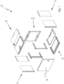
- Fig. 1 shows a perspective view of a wall mount rack system 1 according to the invention. It comprises several individual parts which are shown here in the form of an exploded view.
- the wall mount rack system 1 essentially comprises a multipart framework 2 to serve as a support for some cover arrangements 3, 4, 5, 6 or panels and a hinged door 7.
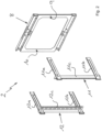
- Fig. 2 illustrates the framework 2 of the wall mount rack system 1 shown in Fig. 1 .
- the framework 2 comprises a base frame 8 as well as a first left side frame 9 and a first right side frame 10.
- the base frame 8 can e. g. be formed by a single rectangular frame or can e. g. feature two bars spaced apart and extending parallel to each other.
- Both side frames 9, 10 are each hingedly connected to the base frame 8, see Fig. 3 .
- the framework 2 also comprises a second left side frame 11 as well as a second right side frame 12, which can be connected to the base frame 8. In the present illustration, however, both second side frames 11, 12 are shown separated from the base frame 8.
- Each of the second side frames 11, 12 has two arms 11a, 11b; 12a, 12b extending parallel to each other , and a crossbar 11c, 12c for connecting the arms 11a, 11b; 12a, 12b of each second side frame 11, 12 to one another.
- Fig. 3 illustrates the function of the base frame 8 more in detail. It is evident that the left side frame 9 as well as the right side frame 10 can be swung out in relation to the base frame 8, as indicated by the broken lines and the two curved arrows, each illustrating a possible swinging movement of the respective side frame 9, 10.
- the swung-in state of the side frames 9, 10 allows for a very small packaging size of the base frame 8 during a transport and/or storage of the framework 2, wherein the swung-out state of the side frames 9, 10 serves for the proper use of the framework 2, namely to at least partially support one of the associated cover arrangements 3, 4, 5, 6, as described in more detail below.
- each of the first side frames 9, 10 has two arms 9a, 9b; 10a, 10b extending parallel to each other , and a crossbar 9c, 10c connecting the arms 9a, 9b; 10a, 10b of each first side frame 9, 10 to one another.
- the arms 9a, 9b; 10a, 10b of each first side frame 9, 10 have a U-shaped cross section, at least in sections and/or regions.
- the arms 11a, 11b; 12a, 12b of each second side frame 11, 12 appear more strip-shaped.
- the arms 11a, 11b; 12a, 12b of each second side frame 11, 12 are designed so as to each of these arms 11a, 11b; 12a, 12b can at least partially be arranged inside the U-shaped cross section of an arm 9a, 9b; 10a, 10b of the associated first side frame 9, 10 (cf. Fig. 4a and Fig. 4b ).
- the base frame 8 is designed to fix the framework 2 to a wall (not shown), if required.
- the base frame 8 may have some passage openings P for example in the form of keyholes, as indicated in Fig. 3 .
- Corresponding fastening means such as screws or bolts (not shown), can be fixed to the wall.
- the base frame 8 can then be attached the wall by passing the heads of the screws or bolts pass through the wider part of the keyholes, wherein a preferably downward movement of the base frame 8 enables the heads to slide behind the smaller part of the keyholes.
- the keyholes shown in Fig. 3 are preferably oriented in opposite directions to prevent the base frame from sliding down and detaching from the wall.
- the base frame 8 can simply be rotated by 180°, relative to its orientation, shown in Fig. 3 to Fig. 7b .
- each of these arms 9a, 9b; 10a, 10b of the first side frames 9, 10 has already been equipped with an at least partially releasable connection means M.
- arms 9a, 9b; 10a, 10b could simply be prepared to receive such a connection means M.
- each of this arms 11a, 11b; 12a, 12b is featured with an elongated slit S.
- each elongated slit S has a widened hole-like zone Z.
- Fig. 4a shows the process during connection of each second side frame 11, 12 to its associated first side frame 9, 10.
- Each hole-like zone Z of the slits S of the arms 11a, 11b; 12a, 12b of both second side frames 11, 12 is designed for passing through a head of one of the connection means M.
- an in contrast thereto smaller portion of this connection means M can at least partially slide inside the elongated slit S of the arm 11a, 11b; 12a, 12b of the second side frame 11, 12.
- each second side frame 11, 12 is slidably couplable to its associated first side frame 9, 10.
- each second side frame 11, 12 is designed to be telescoped with respect to its associated first side frame 9, 10.
- Fig. 4b illustrates an end position of the second side frames 11, 12 relative to the first side frames 9, 10.
- the ready-to-use framework 2 has its smallest possible external dimensions.
- the framework 2 is correspondingly size-flexible.
- a relative movement of its associated second side frame 11, 12 can be prevented. This happens such that the associated arm 11a, 11b; 12a, 12b of this second side frame 11, 12 is then partially clamped between the arm 9a, 9b; 10a, 10b of this first side frame 9, 10 and the head of this connection means M.
- Fig. 5 shows only the cover arrangements 3 - 6 of the wall mount rack system 1 in more detail. These are in particular a left side cover arrangement 3 and a right side cover arrangement 4 as well as a top cover arrangement 5 and a bottom cover arrangement 6.
- Each of this cover arrangements 3 - 6 is constructed of at least two parts. Therefore, the left side cover arrangement 3 comprises a first left side cover 3a and a second left side cover 3b, whereas the right side cover arrangement comprises a first right side cover 4a and a second right side cover 4b.
- the top cover arrangement 5 comprises a first top side cover 5a and a second top side cover 5b, whereas the bottom cover 6 comprises a first bottom side cover 6a and a second bottom cover 6b.
- Fig. 6a and Fig. 6b as well as Fig. 7a and Fig. 7b show the assembly of the framework 2 and the cover arrangements 3 - 6.
- the reason for the two-part construction of the side cover arrangements 3 - 6 is that each of those is thereby flexible in size in order to go along with the possible telescoping of each second side frame 11, 12 with respect to the associated first side frame 9, 10.
- Each first cover arrangement 3a, 4a, 5a, 6a is designed for being coupled to both first side frames 9, 10, wherein each second cover 3b, 4b, 5b, 6b is designed for being coupled to both second side frames 11, 12.
- At least one the first side frames 9, 10 and/or one of the second side frames 11, 12 may feature at least one slot (not shown), whereas at least one of the cover arrangements 3 - 6 may comprise at least one protrusion (not shown) that would fit into a slot of its associated side frame 9, 10; 11, 12.
- This allows for the protrusion of at least one of this cover arrangements 3 - 6 to be at least partially inserted into the slot of its associated and so equipped side frame 9, 10; 11, 12, in order to connect at least this cover arrangement 3 - 6, in particular detachably, to the framework 2.
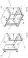
- Fig. 6a shows the first stage of assembling the top cover arrangement 5 and the bottom cover arrangement 6 to the framework 2.
- the first top cover 5a is coupled to the upper arms 9a, 10a of both first side frames 9, 10
- the first bottom cover 6a is coupled to the lower arms 9b, 10b of both first side frames 9, 10.
- Fig. 6b shows the final stage of assembling the top cover arrangement 5 and the bottom cover arrangement 6 to the framework 2.
- the second top cover 5b is coupled with the upper arms 11a, 12a of both second side frames 11, 12, while the second bottom cover 6b is coupled with the lower arms 11b, 12b of both second side frames 11, 12.
- the Fig. 6b shows that each second cover 5b, 6b is arranged above its associated first cover 5a, 6a.
- Fig. 7a shows the first stage of assembling the side cover arrangements 3, 4 to the framework 2.
- the first left side cover 3a is coupled to both arms 9a, 9b of the first left side frame 9, while the first right side cover 4a is coupled to both arms 10a, 10b of the first right side frame 10.
- Fig. 7b shows the final stage of assembling of the side cover arrangements 3, 4 to the framework 2.
- the second left side cover 3b is coupled to both arms 11a, 11b of the second left side frame 11, while the second right side cover 4b is coupled to both arms 12a, 12b of the second right side frame 12.
- Each second cover 3b, 4b is arranged above its associated first cover 3a, 4a.
- Fig. 8 illustrates a wall mount rack 100 according to the invention resulting from fully assembling the above discussed wall mount rack system 1 now finished with the hinged door 7.
- the wall mount rack 100 respectively the assembled wall mount rack system 1 forms a cabinet 101 which limits an interior space 102 (see Fig. 7b ) for accommodating of e.g. electronic and/or network equipment modules (not shown).
- each second cover 3b, 4b, 5b, 6b c in parallel to its associated first cover 3a, 4a, 5a, 6a during telescoping of the framework 2 while covering the sides of the cabinet 101 without any gaps.
- This flexibility in size, illustrated with arrows in Fig. 8 has advantages because the depth d (see Fig. 7b ) of the so limitable interior space 102 of the cabinet 101 can be varied in any stage, namely before and/or during and/or after its assembly.
Landscapes
- Engineering & Computer Science (AREA)
- Microelectronics & Electronic Packaging (AREA)
- Computer Hardware Design (AREA)
- General Engineering & Computer Science (AREA)
- Casings For Electric Apparatus (AREA)
Description
- The invention relates to a wall mount rack system, in particular 19-inch wall mount rack system, for accommodating electronic and/or network equipment modules according to the preamble of
claim 1. Furthermore, the invention relates to a wall mount rack assembled by using said wall mount rack system. - Racks of this type a stationary enclosure for accommodating electronic and/or network equipment modules. These modules usually have lateral mounting elements which allow the module to be fastened to a part of the framework of the rack, for example by bolting or clipping. Typical areas of application for said racks include data centers, laboratories and studios as well as any kind of offices up to home use. Here, 19-inch systems, which serve to accommodate modules or entire assemblies with a standardized width of 19 inches, have essentially become established.
-
CN 206 698 542 U discloses a wall mount rack for electronic and/or network equipment modules. This wall mount rack is based on a framework to support some cover arrangements, namely a left side cover arrangement and a right side cover arrangement as well as a top cover arrangement and a bottom cover arrangement. The so build cabinet has an interior space which can be opened and closed by a door which is hinged to the framework. - Depending on the dimensions of such a rack, transport and storage of an assembled rack can require large space. Therefore, the racks are often stored and delivered in a disassembled state to save transporting space Because of the many individual parts involved, the assembly of the rack can be complicated and thus time-consuming. Because of the large number of possible modules to be accommodated inside the rack and their depth dimensions, standardized racks are often either undersized or oversized with respect to the amount and size of the modules the racks are intended to accommodate.
-
JP 2005 045056 A -
US 2007/144982 A1 discloses a cabinet configured as an equipment rack for a telecommunications infrastructure and therefore at least for electronic equipment modules. The cabinet can be configured with an open frame housing as opposed to an enclosure with doors and so forth. The rack also comprises a framework as a support for angled cover arrangements, each showing a wide side surface with an in contrast shorter angled mounting surface. -
GB 2 569 525 A - Aside from the setbacks mentioned above, the prior art, especially
JP 2005 045056 A - The object of the invention to provide an improved rack that offers a certain degree of flexibility as a response to the above mentioned setbacks and creates a wall mount rack system such that the smallest possible packaging size is achieved.
- According to the invention, this object is achieved by providing a wall mount rack system comprising the features of
claim 1. Favorable embodiments are the subject ofdependent claims 2 to 6. Furthermore, the object is also achieved by a wall mount rack, more particularly a server or network wall mount rack, comprising the features of claim 7. - The core of the invention is that the framework and the cover arrangements are designed to be flexible in size. This means that at least a depth of the so limitable interior space of the cabinet can be varied. Accordingly, the framework as well as the cover arrangements are designed to be customized in size before the rack system is actually assembled to become a rack, and/or when said rack system has been fully assembled and/or is being assembled.
- The wall mounted rack system according to the invention therefore offers, due to its dimensional flexibility, a maximum adaptability to the respective current conditions or needs during its entire service time.
- According to the invention, the framework has a base frame as well as a first left side frame and a first right side frame. Thereby, each of said side frames is hinged to the base frame. Furthermore, the base frame is designed to attach the framework to a wall or the like, wherein each hinged side frame is intended to be swung in and to be swung out relative to said base frame. This enables for the side frames to be swung in - for example during a transport and/or storage of the framework- whereas the side frames are capable of being swung out, e.g. for serving their purpose of supporting at least partially one of the associated side cover arrangements and/or an associated top cover arrangement and/or an associated bottom cover arrangement. This results in the smallest possible packing size for transporting and storage purposes. At the same time, the hinged side frames allow for an extremely simple assembly of the framework.
- The framework does also include a second left side frame as well as a second right side frame. Said second left side frame is slidably couplable to said first left side frame, wherein said second right side frame is slidably couplable to said first right side frame. As a result, each second side frame is designed to be quasi-telescopic relative to the associated first side frame.
- This entails that the depth of the interior space may be varied to support different sized electronic and/or network equipment modules. At the same time, the external dimension of the entire cabinet can be held as small as possible in terms of its depth, as this depends only on the depth of the largest module to be incorporated within the cabinet.
- Said first side frames and said second side frames each comprise two arms and a crossbar connecting said arms of each side frame to one another. Said arms of each side frame extend parallel to each other. The arms of each side frame are designed for being slidably coupled with the arms of the associated side frame.
- Furthermore, the arms of each first side frame may have a U-shaped cross section, at least in sections and/or regions thereof. In addition, the arms of each second side frame may then be designed such that each of said arms can be arranged at least partially in the U-shaped cross section of an arm of the associated first side frame. Based on this, the legs of each U-shaped cross section of the arms of the first side frames act as supports to linearly guide the arms of the second side frames so as to prevent e.g. canting of the touching side frames during a relative movement.
- According to a preferred embodiment, each arm of said first side frames of the wall mount rack system could be equipped with or prepared to receive an at least partially releasable connection means. Each arm of said second side frames comprises an elongated slit with a widened hole-like zone. Each hole-like zone is designed to allow a head of one of the connection means to pass therethrough such that - upon movement of a second side frame relatively to an associated first side frame - an portion of said connection means, being smaller than said head, can at least partially slide inside the elongated slit of the arm of the second side frame. At the same time, a portion of said arm of the second side frame defining respectively limiting the elongated slit can at least be partially guided between the arm of the first side frame and the head of said connection means.
- This prevents unintentional decoupling of the respective second side frame from its associated first side frame while allowing these parts to move relatively to each other in a linear manner.
- In this context, it could come in handy, if a movement of a second side frame relatively to an associated first side frame can be prevented by manipulating at least one of said connection means of the U-shaped arm of the first side frame. This manipulation may be carried out such that the associated strip-shaped arm of the particular second side frame is thereby partially clamped between the U-shaped arm of said particular first side frame and said head of this connection means. For example, the connecting means could be embodied as a screw or a bolt, which is screwed into the U-shaped arm of said first side frame for an appropriate distance for this purpose.
- Preferably, the left side cover arrangement has a first left side cover as well as a second left side cover, wherein the right side cover arrangement could have a first right side cover as well as a second right side cover. Each first side cover is designed to be coupled with the associated first side frame and each second side cover is designed to be coupled with the associated second side frame. These couplings are such that each second side cover is able to be moved parallel to the associated first side cover during telescoping of the associated second side frame with respect to the associated first side frame.
- Advantageously, this can be achieved during telescoping of the framework, by the associated side covers sliding over each other, at least in certain areas. Thus, it is always possible to cover the sides of the cabinet without gaps.
- According to a further embodiment of the present invention, the top cover arrangement may have a first top cover as well as a second top cover, wherein the bottom cover arrangement may have a first bottom cover as well as a second bottom cover. In this embodiment, the first top cover as well as the first bottom cover are designed to be coupled with the associated first side frames, wherein the second top cover as well as the second bottom cover are designed to be coupled with the associated second side frames. Said couplings such that the second top cover is able to be moved parallel to the first top cover, wherein the second bottom cover is able to be moved parallel to the first bottom cover. This possible movement then happens simultaneously for both the first top cover and the first bottom cover during telescoping both second side frames with respect to the associated first side frames.
- Preferably, this can carried out such that during telescoping of the framework, the top covers and the bottom covers slide over each other, at least in certain areas. Thus, it is always possible to cover the top as well as the bottom of the cabinet without gaps.
- At least one of the first side frames and/or one of the second side frames could comprise at least one slot. In this context, at least one of the side cover arrangements could comprise at least one protrusion with corresponds to this slot or one of the slots. Alternatively, or in addition to this, the top cover arrangement and/or the bottom cover arrangement may comprise at least one protrusion corresponding to this slot or one of the slots. Corresponding means that the protrusion of the so equipped cover arrangement/s than may be inserted at least partially into the slot or one of the slots of the so equipped side frame. As a result, the so equipped cover arrangement/s may be, in particular detachably, connected to said framework.
- The above mentioned wall mounted rack system according to the invention allows for a certain degree of flexibility in terms of its dimensions. At the same time, it folding into a transport state rather easily, whereby it can easily assembled on site within a very short time.
- The invention is further directed to a wall mount rack which is based on an assembly respectively installation of the wall mount rack system according to the invention as previously shown.
- The invention is explained in more detail below with reference to a preferred embodiment schematically illustrated in
figures 1-8 . - Fig. 1
- shows a wall mount rack system according to the invention in a perspective view,
- Fig. 2
- depicts the parts of a framework of the wall mount rack system of
figure 1 , - Fig. 3
- shows the parts of the framework of
figure 2 in an at least partially unfolded state of the base frame, - Fig. 4a
- illustrates the parts of the framework of
figure 3 in a full unfolded state at the beginning of their assembly, - Fig. 4b
- shows the parts of
figure 2 to 4a in their full unfolded and assembled state to form the framework, - Fig. 5
- depicts only the cover arrangements of the wall mount rack system of
figure 1 , - Fig. 6a
- shows one part of the top cover arrangement as well as the bottom cover arrangement of the cover arrangements shown
figure 5 in a state fitted to the frameset offigure 4b , - Fig. 6b
- shows the framework of
figure 4b together with the top and bottom cover arrangements offigure 6a mounted thereon, each in their now fully assembled state, - Fig. 7a
- illustrates one part of the side cover arrangements of the entire cover arrangements from
figure 5 in a state fitted to the frameset, together with the top and bottom cover arrangements offigure 6b , - Fig. 7b
- shows the framework of
figure 4b together with the top and bottom cover arrangements offigure 6a as well as the side cover arrangements mounted thereon, each side cover arrangement in its now fully assembled state, and - Fig. 8
- shows a wall mount rack according to the invention, forming a cabinet, as a result of the fully assembled wall mount rack system in a perspective view.
-
Fig. 1 shows a perspective view of a wallmount rack system 1 according to the invention. It comprises several individual parts which are shown here in the form of an exploded view. The wallmount rack system 1 essentially comprises amultipart framework 2 to serve as a support for somecover arrangements -
Fig. 2 illustrates theframework 2 of the wallmount rack system 1 shown inFig. 1 . Theframework 2 comprises abase frame 8 as well as a firstleft side frame 9 and a first right side frame 10. Thebase frame 8 can e. g. be formed by a single rectangular frame or can e. g. feature two bars spaced apart and extending parallel to each other. Both side frames 9, 10 are each hingedly connected to thebase frame 8, seeFig. 3 . Theframework 2 also comprises a secondleft side frame 11 as well as a secondright side frame 12, which can be connected to thebase frame 8. In the present illustration, however, both second side frames 11, 12 are shown separated from thebase frame 8. Each of the second side frames 11, 12 has two arms 11a, 11b; 12a, 12b extending parallel to each other , and acrossbar 11c, 12c for connecting the arms 11a, 11b; 12a, 12b of eachsecond side frame -
Fig. 3 illustrates the function of thebase frame 8 more in detail. It is evident that theleft side frame 9 as well as the right side frame 10 can be swung out in relation to thebase frame 8, as indicated by the broken lines and the two curved arrows, each illustrating a possible swinging movement of therespective side frame 9, 10. The swung-in state of the side frames 9, 10 allows for a very small packaging size of thebase frame 8 during a transport and/or storage of theframework 2, wherein the swung-out state of the side frames 9, 10 serves for the proper use of theframework 2, namely to at least partially support one of the associatedcover arrangements - Likewise the second side frames 11, 12, each of the first side frames 9, 10 has two arms 9a, 9b; 10a, 10b extending parallel to each other , and a crossbar 9c, 10c connecting the arms 9a, 9b; 10a, 10b of each
first side frame 9, 10 to one another. The arms 9a, 9b; 10a, 10b of eachfirst side frame 9, 10 have a U-shaped cross section, at least in sections and/or regions. In contrast, the arms 11a, 11b; 12a, 12b of eachsecond side frame first side frame 9, 10 would be strip-shaped, whereas the arms 11a, 11b; 12a, 12b of eachsecond side frame second side frame first side frame 9, 10 (cf.Fig. 4a and Fig. 4b ). - To enable fastening, the
base frame 8 is designed to fix theframework 2 to a wall (not shown), if required. For this purpose, thebase frame 8 may have some passage openings P for example in the form of keyholes, as indicated inFig. 3 . Corresponding fastening means such as screws or bolts (not shown), can be fixed to the wall. Thebase frame 8 can then be attached the wall by passing the heads of the screws or bolts pass through the wider part of the keyholes, wherein a preferably downward movement of thebase frame 8 enables the heads to slide behind the smaller part of the keyholes. The keyholes shown inFig. 3 are preferably oriented in opposite directions to prevent the base frame from sliding down and detaching from the wall. For this purpose, thebase frame 8 can simply be rotated by 180°, relative to its orientation, shown inFig. 3 to Fig. 7b . - Taking a closer look at the arms 9a, 9b; 10a, 10b of the first side frames 9, 10, each of these arms 9a, 9b; 10a, 10b has already been equipped with an at least partially releasable connection means M. Alternatively, arms 9a, 9b; 10a, 10b could simply be prepared to receive such a connection means M. Taking a closer look at the arms 11a, 11b; 12a, 12b of the second side frames 11, 12 , each of this arms 11a, 11b; 12a, 12b is featured with an elongated slit S. With particular attention to close up portion (circle with a broken line) of the upper arm 11a of the
left side frame 11 inFig. 3 , each elongated slit S has a widened hole-like zone Z. -
Fig. 4a shows the process during connection of eachsecond side frame first side frame 9, 10. Each hole-like zone Z of the slits S of the arms 11a, 11b; 12a, 12b of both second side frames 11, 12 is designed for passing through a head of one of the connection means M. As indicated by the arrows, during a movement of asecond side frame first side frame 9, 10, an in contrast thereto smaller portion of this connection means M can at least partially slide inside the elongated slit S of the arm 11a, 11b; 12a, 12b of thesecond side frame first side frame 9, 10 and the head of the connection means M. Thus, eachsecond side frame first side frame 9, 10. In other words, eachsecond side frame first side frame 9, 10. -
Fig. 4b illustrates an end position of the second side frames 11, 12 relative to the first side frames 9, 10. In this position, the ready-to-use framework 2 has its smallest possible external dimensions. Based on the design of each arm 9a, 9b; 10a, 10b; 11a, 11b; 12a, 12b, theframework 2 is correspondingly size-flexible. By manipulating at least one of the connection means M of an arm 9a, 9b; 10a, 10b of thefirst side frame 9, 10, a relative movement of its associatedsecond side frame second side frame first side frame 9, 10 and the head of this connection means M. -
Fig. 5 shows only the cover arrangements 3 - 6 of the wallmount rack system 1 in more detail. These are in particular a leftside cover arrangement 3 and a rightside cover arrangement 4 as well as atop cover arrangement 5 and abottom cover arrangement 6. Each of this cover arrangements 3 - 6 is constructed of at least two parts. Therefore, the leftside cover arrangement 3 comprises a first left side cover 3a and a second left side cover 3b, whereas the right side cover arrangement comprises a first right side cover 4a and a second right side cover 4b. In addition, thetop cover arrangement 5 comprises a firsttop side cover 5a and a secondtop side cover 5b, whereas thebottom cover 6 comprises a first bottom side cover 6a and asecond bottom cover 6b. -
Fig. 6a and Fig. 6b as well asFig. 7a and Fig. 7b show the assembly of theframework 2 and the cover arrangements 3 - 6. The reason for the two-part construction of the side cover arrangements 3 - 6 is that each of those is thereby flexible in size in order to go along with the possible telescoping of eachsecond side frame first side frame 9, 10. Eachfirst cover arrangement 3a, 4a, 5a, 6a is designed for being coupled to both first side frames 9, 10, wherein eachsecond cover side frame 9, 10; 11, 12. This allows for the protrusion of at least one of this cover arrangements 3 - 6 to be at least partially inserted into the slot of its associated and soequipped side frame 9, 10; 11, 12, in order to connect at least this cover arrangement 3 - 6, in particular detachably, to theframework 2. Certainly, it is possible to use other fastening means to attach at least one cover 3a, 3b; 4a, 4b; 5a, 5b; 6a, 6b of the cover arrangements 3 - 6 to theframework 2. -
Fig. 6a shows the first stage of assembling thetop cover arrangement 5 and thebottom cover arrangement 6 to theframework 2. During the process, the firsttop cover 5a is coupled to the upper arms 9a, 10a of both first side frames 9, 10, while the first bottom cover 6a is coupled to the lower arms 9b, 10b of both first side frames 9, 10. -
Fig. 6b shows the final stage of assembling thetop cover arrangement 5 and thebottom cover arrangement 6 to theframework 2. During the process, the secondtop cover 5b is coupled with theupper arms 11a, 12a of both second side frames 11, 12, while thesecond bottom cover 6b is coupled with thelower arms 11b, 12b of both second side frames 11, 12. TheFig. 6b shows that eachsecond cover first cover 5a, 6a. -
Fig. 7a shows the first stage of assembling theside cover arrangements framework 2. The first left side cover 3a is coupled to both arms 9a, 9b of the firstleft side frame 9, while the first right side cover 4a is coupled to both arms 10a, 10b of the first right side frame 10. -
Fig. 7b shows the final stage of assembling of theside cover arrangements framework 2. The second left side cover 3b is coupled to both arms 11a, 11b of the secondleft side frame 11, while the second right side cover 4b is coupled to botharms right side frame 12. Each second cover 3b, 4b is arranged above its associated first cover 3a, 4a. -
Fig. 8 illustrates awall mount rack 100 according to the invention resulting from fully assembling the above discussed wallmount rack system 1 now finished with the hinged door 7. Thewall mount rack 100 respectively the assembled wallmount rack system 1 forms acabinet 101 which limits an interior space 102 (seeFig. 7b ) for accommodating of e.g. electronic and/or network equipment modules (not shown). - Based on the structure of the so
formed cabinet 101 it is possible to move eachsecond cover first cover 3a, 4a, 5a, 6a during telescoping of theframework 2 while covering the sides of thecabinet 101 without any gaps. This flexibility in size, illustrated with arrows inFig. 8 , has advantages because the depth d (seeFig. 7b ) of the so limitableinterior space 102 of thecabinet 101 can be varied in any stage, namely before and/or during and/or after its assembly.
Claims (8)
- Wall mount rack system (1), in particular 19-inch wall mount rack system, for accommodating electronic and/or network equipment modules, comprising a framework (2) supporting cover arrangements (3, 4, 5, 6) as well as a hinged door (7) to build a cabinet (101) which limits an interior space (102),wherein the framework (2) and the cover arrangements (3, 4, 5, 6) are designed to be size-flexible in such a way that at least a depth (d) of the so limitable interior space (102) of the cabinet (101) can be varied before and/or after being in its fully assembled state and/or during its assembly;wherein the framework (2) comprises a base frame (8) as well as a first left side frame (9) and a first right side frame (10), each being hinged to the base frame (8), wherein the base frame (8) is designed to fix the framework (2) to a wall and each side frame (9, 10) is intended to be swung in relative to the base frame (8), in particular during a transport and/or store of the framework (2), and to be swung out relative to the base frame (8), in particular to support at least partially one of the associated cover arrangements (3, 4, 5, 6), relative to said base frame (8), wherein a second left side frame (11) is slidably couplable to said first left side frame (9), and a second right side frame (12) is slidably couplable to said first right side frame (10), wherein each second side frame (11, 12) is designed to be telescoped with respect to the associated first side frame (9, 10) and wherein said first side frames (9, 10) and said second side frames (11, 12) each comprise two arms (9a, 9b; 10a, 10b; 11a, 11b; 12a, 12b) extending in parallel to each other, and a crossbar (9c, 10c, 11c, 12c) connecting said arms (9a, 9b; 10a, 10b; 11a, 11b; 12a, 12b) of each side frame (9-12) to one another, wherein the arms (9a, 9b; 10a, 10b; 11a, 11b; 12a, 12b) of each side frame (9-12) are designed for being slidably coupled with the arms (9a, 9b; 10a, 10b; 11a, 11b; 12a, 12b) of the associated side frame (9-12).
- Wall mount rack system (1) according to claim 1, characterized in that
the arms (9a, 9b; 10a, 10b) of each first side frame (9, 10) comprise at least in sections and/or regions a U-shaped cross section, wherein the arms (11a, 11b; 12a, 12b) of each second side frame (11, 12) are designed such that each of said arms (11a, 11b; 12a, 12b) can at least partially be arranged in the U-shaped cross section of one arm (9a, 9b; 10a, 10b) of the associated first side frame (9, 10). - Wall mount rack system (1) according to claim 1 or 2, characterized in
that each arm (9a, 9b; 10a, 10b) of said first side frames (9, 10) is equipped with an at least partially releasable connection means (M) or is prepared to receive such a connection means (M), wherein each arm (11a, 11b; 12a, 12b) of said second side frames (11, 12) having an elongated slit (S) with a widened hole-like zone (Z), wherein each hole-like zone (Z) is designed for passing through a head of one of said connection means (M) such that during a movement of a second side frame (11, 12) relatively to an associated first side frame (9, 10), an in contrast smaller part of this connection means (M) can at least partially slide inside said elongated slit (S) of the arm (11a, 11b; 12a, 12b) of the second side frame (11, 12), while a portion of this arm (11a, 11b; 12a, 12b) of said second side frame (11, 12) defining said elongated slit (S) is guided between the arm (9a, 9b; 10a, 10b) of said first side frame (9, 10) and said head of this connection means (M). - Wall mount rack system (1) according to claim 3, characterized in
that a movement of a second side frame (11, 12) relative to an associated first side frame (9, 10) can be prevented by manipulating at least one of the connection means (M) of the arm (9a, 9b; 10a, 10b) of the first side frame (9, 10) such that the associated arm (11a, 11b; 12a, 12b) of this second side frame (11, 12) is partially clamped between said arm (9a, 9b; 10a, 10b) of this first side frame (9, 10) and said head of this connection means (M). - Wall mount rack system (1) according to any of the claims 1 to 4,
characterized in
that said left side cover arrangement (3) has a first left side cover (3a) as well as a second left side cover (3b) and that said right side cover arrangement (4) has a first right side cover (4a) as well as a second right side cover (4b), wherein each first side cover (3a, 4a) is designed for being coupled with the associated first side frame (9, 10) and each second side cover (3b, 4b) is designed for being coupled with the associated second side frame (11, 12) such that each second side cover (3b, 4b) can be moved in parallel to the associated first side cover (3a, 4a) during telescoping of the associated second side frame (11, 12) with respect to the associated first side frame (9, 10). - Wall mount rack system (1) according to any of the claims 1 to 5,
characterized in
that the top cover arrangement (5) has a first top cover (5a) as well as a second top cover (5b) and that the bottom cover arrangement (6) has a first bottom cover (6a) as well as a second bottom cover (6b), wherein the first top cover (5a) as well as the first bottom cover (6a) are designed for being coupled with the associated first side frames (9, 10) and the second top cover (5b) as well as the second bottom cover (6b) are designed for being coupled with the associated second side frames (11, 12) such that the second top cover (5b) can be moved in parallel to the associated first top cover (5a) and that the second bottom cover (6b) can be moved in parallel to the associated first bottom cover (6a) during telescoping of the second side frames (11, 12) with respect to the associated first side frames (9, 10). - Wall mount rack system (1) according to any of the claims 1 to 6,
characterized in
that at least one said first side frames (9, 10) and/or one of said second side frames (11, 12) comprises at least one slot, wherein at least one of said side cover arrangements (3, 4) and/or said top cover arrangement (5) and/or said bottom cover arrangement (6) comprises at least one protrusion corresponding to this slot in such a way that the protrusion of at least one of this cover arrangements (3 - 6) can at least partially be inserted into the slot of the so equipped side frame (9, 10; 11, 12) in order to connect at least this cover arrangement (3 - 6), in particular detachably, to said framework (2). - Wall mount rack (100), comprising an assembly of the wall mount rack system (1) according to any one of the preceding claims.
Priority Applications (2)
| Application Number | Priority Date | Filing Date | Title |
|---|---|---|---|
| PL22159428.6T PL4240124T3 (en) | 2022-03-01 | 2022-03-01 | Wall mount rack for electronic equipment |
| EP22159428.6A EP4240124B1 (en) | 2022-03-01 | 2022-03-01 | Wall mount rack for electronic equipment |
Applications Claiming Priority (1)
| Application Number | Priority Date | Filing Date | Title |
|---|---|---|---|
| EP22159428.6A EP4240124B1 (en) | 2022-03-01 | 2022-03-01 | Wall mount rack for electronic equipment |
Publications (3)
| Publication Number | Publication Date |
|---|---|
| EP4240124A1 EP4240124A1 (en) | 2023-09-06 |
| EP4240124B1 true EP4240124B1 (en) | 2025-05-21 |
| EP4240124C0 EP4240124C0 (en) | 2025-05-21 |
Family
ID=80623793
Family Applications (1)
| Application Number | Title | Priority Date | Filing Date |
|---|---|---|---|
| EP22159428.6A Active EP4240124B1 (en) | 2022-03-01 | 2022-03-01 | Wall mount rack for electronic equipment |
Country Status (2)
| Country | Link |
|---|---|
| EP (1) | EP4240124B1 (en) |
| PL (1) | PL4240124T3 (en) |
Family Cites Families (8)
| Publication number | Priority date | Publication date | Assignee | Title |
|---|---|---|---|---|
| JP4180990B2 (en) * | 2003-07-23 | 2008-11-12 | 河村電器産業株式会社 | Cabinet rack structure |
| US7946433B2 (en) * | 2005-12-27 | 2011-05-24 | Telect Inc. | Interlocking upright rack members |
| FR2987218B1 (en) * | 2012-02-21 | 2014-02-14 | Schneider Electric Ind Sas | OSSATURE OF A BOX OR AN ELECTRICAL CABINET |
| JP2016184686A (en) * | 2015-03-26 | 2016-10-20 | 日本電気株式会社 | Housing rack and depth adjustment method of housing rack |
| CN205320434U (en) * | 2016-01-27 | 2016-06-15 | 宁波龙图通讯科技有限公司 | Pull formula network frame |
| CN206698542U (en) | 2017-02-28 | 2017-12-01 | 东莞市湘华五金科技有限公司 | Reinforcement type indoor machine cabinet with Compound Cavity |
| GB2569525A (en) * | 2017-11-17 | 2019-06-26 | Shafiq Mohammed | Improvements in network server cabinets and racking enclosures |
| CN109348653A (en) * | 2018-10-22 | 2019-02-15 | 华为技术有限公司 | Folding cabinet frame and cabinet |
-
2022
- 2022-03-01 PL PL22159428.6T patent/PL4240124T3/en unknown
- 2022-03-01 EP EP22159428.6A patent/EP4240124B1/en active Active
Also Published As
| Publication number | Publication date |
|---|---|
| PL4240124T3 (en) | 2025-09-15 |
| EP4240124A1 (en) | 2023-09-06 |
| EP4240124C0 (en) | 2025-05-21 |
Similar Documents
| Publication | Publication Date | Title |
|---|---|---|
| US5921402A (en) | Cable management track system | |
| US6988626B2 (en) | Computer component rack mounting arrangement | |
| US6655534B2 (en) | Configurable rack rail system for dual mount configurations | |
| US7293666B2 (en) | Equipment enclosure kit and assembly method | |
| US20030039094A1 (en) | Closure for equipment case having an integrated display | |
| US6854605B2 (en) | Cable management system | |
| US20020153814A1 (en) | Storage cabinet for electronic components | |
| US5940937A (en) | Dual directional hinged wallmount bracket assembly | |
| US5975962A (en) | Network shelf system | |
| US6206494B1 (en) | Assembly unit with an assembly rail | |
| US20090085449A1 (en) | Extension apparatus for previously installed electrical cabinets | |
| US6218615B1 (en) | Communication equipment rack | |
| US6364439B1 (en) | Computer storage systems for computer facilities | |
| EP4240124A1 (en) | Wall mount rack for electronic equipment | |
| US20190098790A1 (en) | Angular Vertical Cable Manager | |
| US20250247994A1 (en) | Electronic equipment enclosure with enhanced mounting flexibility | |
| US20250311169A1 (en) | Airflow management system for power module | |
| US9992557B2 (en) | Rack mountable security enclosures | |
| US6675722B2 (en) | Workhorse table base | |
| US12484169B2 (en) | Dynamic client fiber trough and hinge assemblies for a rack or cabinet system | |
| JPS63140599A (en) | Communication equipment cabinet | |
| US20070144982A1 (en) | Interlocking Upright Rack Members | |
| US12302527B2 (en) | Electronic equipment enclosure with enhanced mounting flexibility | |
| US20240224458A1 (en) | Auxiliary side rack | |
| EP1151511B1 (en) | An electrical cabinet and a frame therefor |
Legal Events
| Date | Code | Title | Description |
|---|---|---|---|
| PUAI | Public reference made under article 153(3) epc to a published international application that has entered the european phase |
Free format text: ORIGINAL CODE: 0009012 |
|
| STAA | Information on the status of an ep patent application or granted ep patent |
Free format text: STATUS: REQUEST FOR EXAMINATION WAS MADE |
|
| 17P | Request for examination filed |
Effective date: 20230626 |
|
| AK | Designated contracting states |
Kind code of ref document: A1 Designated state(s): AL AT BE BG CH CY CZ DE DK EE ES FI FR GB GR HR HU IE IS IT LI LT LU LV MC MK MT NL NO PL PT RO RS SE SI SK SM TR |
|
| RAX | Requested extension states of the european patent have changed |
Extension state: ME Payment date: 20231012 Extension state: BA Payment date: 20231012 |
|
| RBV | Designated contracting states (corrected) |
Designated state(s): AL AT BE BG CH CY CZ DE DK EE ES FI FR GB GR HR HU IE IS IT LI LT LU LV MC MK MT NL NO PL PT RO RS SE SI SK SM TR |
|
| STAA | Information on the status of an ep patent application or granted ep patent |
Free format text: STATUS: EXAMINATION IS IN PROGRESS |
|
| GRAP | Despatch of communication of intention to grant a patent |
Free format text: ORIGINAL CODE: EPIDOSNIGR1 |
|
| STAA | Information on the status of an ep patent application or granted ep patent |
Free format text: STATUS: GRANT OF PATENT IS INTENDED |
|
| 17Q | First examination report despatched |
Effective date: 20250218 |
|
| INTG | Intention to grant announced |
Effective date: 20250311 |
|
| GRAS | Grant fee paid |
Free format text: ORIGINAL CODE: EPIDOSNIGR3 |
|
| GRAA | (expected) grant |
Free format text: ORIGINAL CODE: 0009210 |
|
| STAA | Information on the status of an ep patent application or granted ep patent |
Free format text: STATUS: THE PATENT HAS BEEN GRANTED |
|
| AK | Designated contracting states |
Kind code of ref document: B1 Designated state(s): AL AT BE BG CH CY CZ DE DK EE ES FI FR GB GR HR HU IE IS IT LI LT LU LV MC MK MT NL NO PL PT RO RS SE SI SK SM TR |
|
| REG | Reference to a national code |
Ref country code: GB Ref legal event code: FG4D |
|
| REG | Reference to a national code |
Ref country code: CH Ref legal event code: EP |
|
| REG | Reference to a national code |
Ref country code: DE Ref legal event code: R096 Ref document number: 602022014818 Country of ref document: DE |
|
| REG | Reference to a national code |
Ref country code: IE Ref legal event code: FG4D |
|
| U01 | Request for unitary effect filed |
Effective date: 20250604 |
|
| U07 | Unitary effect registered |
Designated state(s): AT BE BG DE DK EE FI FR IT LT LU LV MT NL PT RO SE SI Effective date: 20250611 |
|
| PG25 | Lapsed in a contracting state [announced via postgrant information from national office to epo] |
Ref country code: ES Free format text: LAPSE BECAUSE OF FAILURE TO SUBMIT A TRANSLATION OF THE DESCRIPTION OR TO PAY THE FEE WITHIN THE PRESCRIBED TIME-LIMIT Effective date: 20250521 |
|
| PG25 | Lapsed in a contracting state [announced via postgrant information from national office to epo] |
Ref country code: GR Free format text: LAPSE BECAUSE OF FAILURE TO SUBMIT A TRANSLATION OF THE DESCRIPTION OR TO PAY THE FEE WITHIN THE PRESCRIBED TIME-LIMIT Effective date: 20250822 |
|
| PG25 | Lapsed in a contracting state [announced via postgrant information from national office to epo] |
Ref country code: HR Free format text: LAPSE BECAUSE OF FAILURE TO SUBMIT A TRANSLATION OF THE DESCRIPTION OR TO PAY THE FEE WITHIN THE PRESCRIBED TIME-LIMIT Effective date: 20250521 |
|
| PG25 | Lapsed in a contracting state [announced via postgrant information from national office to epo] |
Ref country code: RS Free format text: LAPSE BECAUSE OF FAILURE TO SUBMIT A TRANSLATION OF THE DESCRIPTION OR TO PAY THE FEE WITHIN THE PRESCRIBED TIME-LIMIT Effective date: 20250821 |
|
| PG25 | Lapsed in a contracting state [announced via postgrant information from national office to epo] |
Ref country code: IS Free format text: LAPSE BECAUSE OF FAILURE TO SUBMIT A TRANSLATION OF THE DESCRIPTION OR TO PAY THE FEE WITHIN THE PRESCRIBED TIME-LIMIT Effective date: 20250921 |
|
| PG25 | Lapsed in a contracting state [announced via postgrant information from national office to epo] |
Ref country code: SM Free format text: LAPSE BECAUSE OF FAILURE TO SUBMIT A TRANSLATION OF THE DESCRIPTION OR TO PAY THE FEE WITHIN THE PRESCRIBED TIME-LIMIT Effective date: 20250521 |
|
| PG25 | Lapsed in a contracting state [announced via postgrant information from national office to epo] |
Ref country code: SK Free format text: LAPSE BECAUSE OF FAILURE TO SUBMIT A TRANSLATION OF THE DESCRIPTION OR TO PAY THE FEE WITHIN THE PRESCRIBED TIME-LIMIT Effective date: 20250521 |
|
| PLBE | No opposition filed within time limit |
Free format text: ORIGINAL CODE: 0009261 |
|
| STAA | Information on the status of an ep patent application or granted ep patent |
Free format text: STATUS: NO OPPOSITION FILED WITHIN TIME LIMIT |
|
| REG | Reference to a national code |
Ref country code: CH Ref legal event code: U11 Free format text: ST27 STATUS EVENT CODE: U-0-0-U10-U11 (AS PROVIDED BY THE NATIONAL OFFICE) Effective date: 20260401 |
|
| REG | Reference to a national code |
Ref country code: CH Ref legal event code: L10 Free format text: ST27 STATUS EVENT CODE: U-0-0-L10-L00 (AS PROVIDED BY THE NATIONAL OFFICE) Effective date: 20260402 |
|
| PGFP | Annual fee paid to national office [announced via postgrant information from national office to epo] |
Ref country code: NO Payment date: 20260313 Year of fee payment: 5 |
|
| PGFP | Annual fee paid to national office [announced via postgrant information from national office to epo] |
Ref country code: TR Payment date: 20260227 Year of fee payment: 5 |
|
| PGFP | Annual fee paid to national office [announced via postgrant information from national office to epo] |
Ref country code: CZ Payment date: 20260303 Year of fee payment: 5 |
|
| PGFP | Annual fee paid to national office [announced via postgrant information from national office to epo] |
Ref country code: PL Payment date: 20260224 Year of fee payment: 5 |
|
| 26N | No opposition filed |
Effective date: 20260224 |
|
| U20 | Renewal fee for the european patent with unitary effect paid |
Year of fee payment: 5 Effective date: 20260325 |