EP4239995A1 - Image forming apparatus, method, computer program, and computer-readable medium - Google Patents
Image forming apparatus, method, computer program, and computer-readable medium Download PDFInfo
- Publication number
- EP4239995A1 EP4239995A1 EP23158843.5A EP23158843A EP4239995A1 EP 4239995 A1 EP4239995 A1 EP 4239995A1 EP 23158843 A EP23158843 A EP 23158843A EP 4239995 A1 EP4239995 A1 EP 4239995A1
- Authority
- EP
- European Patent Office
- Prior art keywords
- image forming
- mode
- forming apparatus
- trigger frame
- communication
- Prior art date
- Legal status (The legal status is an assumption and is not a legal conclusion. Google has not performed a legal analysis and makes no representation as to the accuracy of the status listed.)
- Pending
Links
Images



Classifications
-
- G—PHYSICS
- G06—COMPUTING OR CALCULATING; COUNTING
- G06F—ELECTRIC DIGITAL DATA PROCESSING
- G06F3/00—Input arrangements for transferring data to be processed into a form capable of being handled by the computer; Output arrangements for transferring data from processing unit to output unit, e.g. interface arrangements
- G06F3/12—Digital output to print unit, e.g. line printer, chain printer
- G06F3/1201—Dedicated interfaces to print systems
- G06F3/1278—Dedicated interfaces to print systems specifically adapted to adopt a particular infrastructure
- G06F3/1292—Mobile client, e.g. wireless printing
-
- H—ELECTRICITY
- H04—ELECTRIC COMMUNICATION TECHNIQUE
- H04N—PICTORIAL COMMUNICATION, e.g. TELEVISION
- H04N1/00—Scanning, transmission or reproduction of documents or the like, e.g. facsimile transmission; Details thereof
- H04N1/32—Circuits or arrangements for control or supervision between transmitter and receiver or between image input and image output device, e.g. between a still-image camera and its memory or between a still-image camera and a printer device
- H04N1/327—Initiating, continuing or ending a single-mode communication; Handshaking therefor
- H04N1/32797—Systems adapted to communicate over more than one channel, e.g. via ISDN
-
- H—ELECTRICITY
- H04—ELECTRIC COMMUNICATION TECHNIQUE
- H04W—WIRELESS COMMUNICATION NETWORKS
- H04W74/00—Wireless channel access
- H04W74/08—Non-scheduled access, e.g. ALOHA
- H04W74/0808—Non-scheduled access, e.g. ALOHA using carrier sensing, e.g. carrier sense multiple access [CSMA]
-
- G—PHYSICS
- G06—COMPUTING OR CALCULATING; COUNTING
- G06F—ELECTRIC DIGITAL DATA PROCESSING
- G06F3/00—Input arrangements for transferring data to be processed into a form capable of being handled by the computer; Output arrangements for transferring data from processing unit to output unit, e.g. interface arrangements
- G06F3/12—Digital output to print unit, e.g. line printer, chain printer
- G06F3/1201—Dedicated interfaces to print systems
- G06F3/1202—Dedicated interfaces to print systems specifically adapted to achieve a particular effect
- G06F3/1218—Reducing or saving of used resources, e.g. avoiding waste of consumables or improving usage of hardware resources
- G06F3/122—Reducing or saving of used resources, e.g. avoiding waste of consumables or improving usage of hardware resources with regard to computing resources, e.g. memory, CPU
-
- G—PHYSICS
- G06—COMPUTING OR CALCULATING; COUNTING
- G06F—ELECTRIC DIGITAL DATA PROCESSING
- G06F3/00—Input arrangements for transferring data to be processed into a form capable of being handled by the computer; Output arrangements for transferring data from processing unit to output unit, e.g. interface arrangements
- G06F3/12—Digital output to print unit, e.g. line printer, chain printer
- G06F3/1201—Dedicated interfaces to print systems
- G06F3/1223—Dedicated interfaces to print systems specifically adapted to use a particular technique
- G06F3/1236—Connection management
-
- H—ELECTRICITY
- H04—ELECTRIC COMMUNICATION TECHNIQUE
- H04N—PICTORIAL COMMUNICATION, e.g. TELEVISION
- H04N1/00—Scanning, transmission or reproduction of documents or the like, e.g. facsimile transmission; Details thereof
- H04N1/00095—Systems or arrangements for the transmission of the picture signal
- H04N1/00103—Systems or arrangements for the transmission of the picture signal specially adapted for radio transmission, e.g. via satellites
-
- H—ELECTRICITY
- H04—ELECTRIC COMMUNICATION TECHNIQUE
- H04N—PICTORIAL COMMUNICATION, e.g. TELEVISION
- H04N1/00—Scanning, transmission or reproduction of documents or the like, e.g. facsimile transmission; Details thereof
- H04N1/00127—Connection or combination of a still picture apparatus with another apparatus, e.g. for storage, processing or transmission of still picture signals or of information associated with a still picture
- H04N1/00281—Connection or combination of a still picture apparatus with another apparatus, e.g. for storage, processing or transmission of still picture signals or of information associated with a still picture with a telecommunication apparatus, e.g. a switched network of teleprinters for the distribution of text-based information, a selective call terminal
- H04N1/00307—Connection or combination of a still picture apparatus with another apparatus, e.g. for storage, processing or transmission of still picture signals or of information associated with a still picture with a telecommunication apparatus, e.g. a switched network of teleprinters for the distribution of text-based information, a selective call terminal with a mobile telephone apparatus
-
- H—ELECTRICITY
- H04—ELECTRIC COMMUNICATION TECHNIQUE
- H04N—PICTORIAL COMMUNICATION, e.g. TELEVISION
- H04N1/00—Scanning, transmission or reproduction of documents or the like, e.g. facsimile transmission; Details thereof
- H04N1/00127—Connection or combination of a still picture apparatus with another apparatus, e.g. for storage, processing or transmission of still picture signals or of information associated with a still picture
- H04N1/00281—Connection or combination of a still picture apparatus with another apparatus, e.g. for storage, processing or transmission of still picture signals or of information associated with a still picture with a telecommunication apparatus, e.g. a switched network of teleprinters for the distribution of text-based information, a selective call terminal
- H04N1/00315—Connection or combination of a still picture apparatus with another apparatus, e.g. for storage, processing or transmission of still picture signals or of information associated with a still picture with a telecommunication apparatus, e.g. a switched network of teleprinters for the distribution of text-based information, a selective call terminal with a radio transmission apparatus
-
- H—ELECTRICITY
- H04—ELECTRIC COMMUNICATION TECHNIQUE
- H04N—PICTORIAL COMMUNICATION, e.g. TELEVISION
- H04N1/00—Scanning, transmission or reproduction of documents or the like, e.g. facsimile transmission; Details thereof
- H04N1/00795—Reading arrangements
-
- H—ELECTRICITY
- H04—ELECTRIC COMMUNICATION TECHNIQUE
- H04N—PICTORIAL COMMUNICATION, e.g. TELEVISION
- H04N1/00—Scanning, transmission or reproduction of documents or the like, e.g. facsimile transmission; Details thereof
- H04N1/00962—Input arrangements for operating instructions or parameters, e.g. updating internal software
- H04N1/00973—Input arrangements for operating instructions or parameters, e.g. updating internal software from a remote device, e.g. receiving via the internet instructions input to a computer terminal
-
- H—ELECTRICITY
- H04—ELECTRIC COMMUNICATION TECHNIQUE
- H04N—PICTORIAL COMMUNICATION, e.g. TELEVISION
- H04N1/00—Scanning, transmission or reproduction of documents or the like, e.g. facsimile transmission; Details thereof
- H04N1/32—Circuits or arrangements for control or supervision between transmitter and receiver or between image input and image output device, e.g. between a still-image camera and its memory or between a still-image camera and a printer device
- H04N1/327—Initiating, continuing or ending a single-mode communication; Handshaking therefor
- H04N1/32789—Details of handshaking
- H04N1/32791—Arrangements for reducing the handshaking procedure or protocol time
-
- H—ELECTRICITY
- H04—ELECTRIC COMMUNICATION TECHNIQUE
- H04W—WIRELESS COMMUNICATION NETWORKS
- H04W72/00—Local resource management
- H04W72/04—Wireless resource allocation
- H04W72/044—Wireless resource allocation based on the type of the allocated resource
-
- H—ELECTRICITY
- H04—ELECTRIC COMMUNICATION TECHNIQUE
- H04W—WIRELESS COMMUNICATION NETWORKS
- H04W76/00—Connection management
- H04W76/10—Connection setup
- H04W76/14—Direct-mode setup
-
- H—ELECTRICITY
- H04—ELECTRIC COMMUNICATION TECHNIQUE
- H04W—WIRELESS COMMUNICATION NETWORKS
- H04W84/00—Network topologies
- H04W84/02—Hierarchically pre-organised networks, e.g. paging networks, cellular networks, WLAN [Wireless Local Area Network] or WLL [Wireless Local Loop]
- H04W84/10—Small scale networks; Flat hierarchical networks
- H04W84/12—WLAN [Wireless Local Area Networks]
-
- H—ELECTRICITY
- H04—ELECTRIC COMMUNICATION TECHNIQUE
- H04W—WIRELESS COMMUNICATION NETWORKS
- H04W84/00—Network topologies
- H04W84/18—Self-organising networks, e.g. ad-hoc networks or sensor networks
-
- H—ELECTRICITY
- H04—ELECTRIC COMMUNICATION TECHNIQUE
- H04N—PICTORIAL COMMUNICATION, e.g. TELEVISION
- H04N2201/00—Indexing scheme relating to scanning, transmission or reproduction of documents or the like, and to details thereof
- H04N2201/0008—Connection or combination of a still picture apparatus with another apparatus
- H04N2201/0034—Details of the connection, e.g. connector, interface
- H04N2201/0037—Topological details of the connection
- H04N2201/0039—Connection via a network
-
- H—ELECTRICITY
- H04—ELECTRIC COMMUNICATION TECHNIQUE
- H04N—PICTORIAL COMMUNICATION, e.g. TELEVISION
- H04N2201/00—Indexing scheme relating to scanning, transmission or reproduction of documents or the like, and to details thereof
- H04N2201/0008—Connection or combination of a still picture apparatus with another apparatus
- H04N2201/0034—Details of the connection, e.g. connector, interface
- H04N2201/0037—Topological details of the connection
- H04N2201/0041—Point to point
-
- H—ELECTRICITY
- H04—ELECTRIC COMMUNICATION TECHNIQUE
- H04N—PICTORIAL COMMUNICATION, e.g. TELEVISION
- H04N2201/00—Indexing scheme relating to scanning, transmission or reproduction of documents or the like, and to details thereof
- H04N2201/0008—Connection or combination of a still picture apparatus with another apparatus
- H04N2201/0034—Details of the connection, e.g. connector, interface
- H04N2201/0048—Type of connection
- H04N2201/0055—By radio
-
- H—ELECTRICITY
- H04—ELECTRIC COMMUNICATION TECHNIQUE
- H04N—PICTORIAL COMMUNICATION, e.g. TELEVISION
- H04N2201/00—Indexing scheme relating to scanning, transmission or reproduction of documents or the like, and to details thereof
- H04N2201/0077—Types of the still picture apparatus
- H04N2201/0094—Multifunctional device, i.e. a device capable of all of reading, reproducing, copying, facsimile transception, file transception
-
- Y—GENERAL TAGGING OF NEW TECHNOLOGICAL DEVELOPMENTS; GENERAL TAGGING OF CROSS-SECTIONAL TECHNOLOGIES SPANNING OVER SEVERAL SECTIONS OF THE IPC; TECHNICAL SUBJECTS COVERED BY FORMER USPC CROSS-REFERENCE ART COLLECTIONS [XRACs] AND DIGESTS
- Y02—TECHNOLOGIES OR APPLICATIONS FOR MITIGATION OR ADAPTATION AGAINST CLIMATE CHANGE
- Y02D—CLIMATE CHANGE MITIGATION TECHNOLOGIES IN INFORMATION AND COMMUNICATION TECHNOLOGIES [ICT], I.E. INFORMATION AND COMMUNICATION TECHNOLOGIES AIMING AT THE REDUCTION OF THEIR OWN ENERGY USE
- Y02D10/00—Energy efficient computing, e.g. low power processors, power management or thermal management
Definitions
- the present invention relates to an image forming apparatus, a method, a computer program, and a computer-readable medium.
- Japanese Patent Application Laid-Open No. 2012-19487 discusses a technique in which an image forming apparatus can perform wireless communication in an infrastructure mode and wireless communication in an ad hoc mode in parallel via an access point.
- an image forming apparatus as specified in claims 1 to 8.
- a method as specified in claim 9.
- a computer program as specified in claim 10.
- a computer-readable medium as specified in claim 11.
- Fig. 1 illustrates an example of a configuration of a system according to an embodiment of the present invention.
- the system is an example of a wireless communication system where a plurality of communication apparatuses can wirelessly communicate with each other.
- the system includes an access point 131, a multifunction peripheral (MFP) 151, and a mobile terminal 101.
- the mobile terminal 101 is an example of a mobile terminal and is a laptop personal computer or a smartphone.
- the MFP 151 has a printing function, a reading function (a scanner function), and a facsimile function.
- the MFP 151 according to the present embodiment also has a communication function capable of wirelessly communicating with the mobile terminal 101. While a case where the MFP 151 is used as an image forming apparatus is described in the present embodiment, the present embodiment is not limited thereto. For example, a facsimile apparatus, a scanner apparatus, a projector, or a single-function printing apparatus may be used instead of the MFP 151. In the present embodiment, an apparatus having a printing function is also referred to as an image forming apparatus.
- the access point 131 is provided separately from (outside) the mobile terminal 101 and the MFP 151, and operates as a base station apparatus in a wireless local area network (WLAN).
- the access point 131 is also referred to as the external access point 131 or the external wireless base station (or the external master station).
- the MFP 151 having a WLAN communication function can perform communication in a WLAN infrastructure mode via the access point 131.
- an access point is also referred to as an "AP”.
- the infrastructure mode is also referred to as the "wireless infrastructure mode”.
- the infrastructure mode is a mode in which the MFP 151 communicates with another apparatus via an external apparatus (e.g., the access point 131) forming a network.
- a connection to the external access point 131 established by the MFP 151 operating in the infrastructure mode is referred to as an infrastructure connection.
- the MFP 151 operates as a slave station, and the external access point 131 operates as a master station.
- the master station refers to an apparatus that determines a communication channel to be used in a network to which the master station belongs
- the slave station refers to an apparatus that does not determine a communication channel to be used in a network to which the slave station belongs, and uses the communication channel determined by the master station.
- the access point 131 wirelessly communicates with a communication apparatus (an authenticated communication apparatus) permitted to connect to the access point 131, and relays wireless communication between the communication apparatus and another communication apparatus.
- the access point 131 can also be connected to, for example, a wired communication network and can relay communication between a communication apparatus connected to the wired communication network and another communication apparatus wirelessly connected to the access point 131.
- the mobile terminal 101 and the MFP 151 can wirelessly communicate with each other in the wireless infrastructure mode via the external access point 131 or in a peer-to-peer mode not via the external access point 131, using respective WLAN communication functions of the mobile terminal 101 and the MFP 151.
- peer-to-peer is referred to as "P2P".
- Communication not performed via the external access point 131 is also referred to as direct wireless communication.
- the P2P mode includes Wi-Fi Direct ® and a software AP mode.
- the P2P mode can also be compliant with the Institute of Electrical and Electronics Engineers (IEEE) 802.11 series.
- the P2P mode refers to a mode in which the MFP 151 directly communicates with another apparatus such as the mobile terminal 101. That is, the communication is not performed via an external apparatus that forms a network.
- the P2P mode includes an AP mode where the MFP 151 operates as an access point. Connection information (a Service Set Identifier (SSID) and a password) relating to the access point enabled in the MFP 151 in the AP mode can be optionally set by a user.
- the P2P mode may include, for example, a Wi-Fi Direct ® mode for the MFP 151 to communicate using Wi-Fi Direct ® .
- Which of Wi-Fi Direct ® -compatible devices is to operate as the master station is determined, for example, according to a sequence termed "group owner negotiation". Alternatively, the master station may be determined without executing the group owner negotiation.
- An apparatus that is a Wi-Fi Direct ® -compatible device and serves as the master station is particularly referred to as a group owner.
- a connection to another apparatus established by the MFP 151 operating in the P2P mode is referred to as a direct connection. In the present embodiment, in the direct connection, the MFP 151 operates as the master station, and another apparatus (e.g., the mobile terminal 101) operates as the slave station.
- the mobile terminal 101 includes an input interface 102, a central processing unit (CPU) 103, a read-only memory (ROM) 104, a random-access memory (RAM) 105, an external storage device 106, an output interface 107, a display unit 108, a keyboard 109, a communication unit 110, a short-range wireless communication unit 111, a network interface 112, and a Universal Serial Bus (USB) interface 113.
- the CPU 103, the ROM 104, and the RAM 105 form a computer of the mobile terminal 101.
- the input interface 102 receives input data or an operation instruction from the user operating an operation unit such as the keyboard 109.
- the operation unit may be a physical keyboard or physical buttons, or may be a software keyboard or software buttons displayed on the display unit 108.
- the input interface 102 may receive an input (an operation) from the user through the display unit 108.
- the CPU 103 is a system control unit and controls the entire mobile terminal 101.
- the ROM 104 stores fixed data such as control programs to be executed by the CPU 103, a data table, and an embedded operating system (hereinafter referred to as an embedded OS).
- the control programs stored in the ROM 104 perform software execution control such as scheduling, task switching, and interrupt processing under control of the embedded OS stored in the ROM 104.
- the RAM 105 includes a static random-access memory (SRAM) using a backup power supply.
- SRAM static random-access memory
- data is held by a primary battery (not illustrated) for data backup.
- the RAM 105 can store important data such as a program control variable without volatilizing the data.
- a memory area for storing setting information regarding the mobile terminal 101 and management data on the mobile terminal 101 is also provided in the RAM 105.
- the RAM 105 is also used as a main memory or a work memory of the CPU 103.
- the external storage device 106 stores a print information generation program for generating print information that can be interpreted by the MFP 151.
- the output interface 107 controls the display unit 108 to display data or provide a notification of the state of the mobile terminal 101.
- the display unit 108 includes a light-emitting diode (LED) or a liquid crystal display (LCD).
- the display unit 108 displays data or provides a notification of the state of the mobile terminal 101.
- the communication unit 110 is configured to connect to an apparatus such as the MFP 151 or the access point (AP) 131 to perform data communication.
- the communication unit 110 is connectable to the access point (not illustrated) in the MFP 151.
- the communication unit 110 and the access point in the MFP 151 are connected to each other, whereby the mobile terminal 101 and the MFP 151 can perform P2P communication therebetween.
- the communication unit 110 may directly communicate with the MFP 151 through wireless communication, or may communicate with the MFP 151 via an external apparatus outside the mobile terminal 101 and the MFP 151.
- the external apparatus examples include an external access point (e.g., the access point 131) outside the mobile terminal 101 and the MFP 151, and an apparatus, other than an access point, capable of relaying communication.
- the wireless communication method used by the communication unit 110 is Wireless Fidelity (Wi-Fi ® ) which is a communication standard compliant with the IEEE 802.11 series.
- the access point 131 include a device such as a WLAN router.
- the short-range wireless communication unit 111 is configured to wirelessly connect to an apparatus such as the MFP 151 over a short range to perform data communication.
- the short-range wireless communication unit 111 performs communication using a communication method different from that of the communication unit 110.
- the short-range wireless communication unit 111 is connectable to, for example, a short-range wireless communication unit 157 in the MFP 151.
- Examples of the communication method include near-field communication (NFC), Bluetooth ® Classic, Bluetooth ® Low Energy, and Wi-Fi Aware ® .
- the network interface 112 is a connection interface (I/F) that controls wireless communication and communication processing via a wired LAN cable.
- I/F connection interface
- the USB interface 113 is a connection I/F that controls a USB connection via a USB cable. More specifically, the USB interface 113 connects to an apparatus such as the MFP 151 or the external access point 131 via a USB cable to perform data communication.
- the MFP 151 includes a ROM 152, a RAM 153, a CPU 154, a print engine 155, a communication unit 156, the short-range wireless communication unit 157, an input interface 158, an operation unit 159, an output interface 160, a display unit 161, a network interface 162, and a USB interface 163.
- the ROM 152, the RAM 153, and the CPU 154 form a computer of the MFP 151.
- the communication unit 156 controls communication processing using the respective interfaces.
- the MFP 151 can operate in the infrastructure mode and the P2P mode which are communication modes using the communication unit 156.
- the communication unit 156 can operate as an internal access point inside the MFP 151.
- the user instructs the MFP 151 to enable the internal access point, whereby the MFP 151 operates as an access point.
- the wireless communication method used by the communication unit 156 is a communication standard compliant with the IEEE 802.11 series.
- Wi-Fi ® Wi-Fi ® communication
- the communication unit 156 may include hardware functioning as an access point, or may operate as an access point using software for causing the communication unit 156 to function as an access point.
- the communication unit 156 can maintain P2P wireless connections with a predetermined number or less than the predetermined number of (e.g., three or less) slave station apparatuses in parallel.
- the P2P wireless connection may be maintained with three slave stations in parallel or it may be maintained with less than three slave stations in parallel.
- the communication unit 156 can perform wireless communication using a frequency band selected from among 2.4 GHz, 5 GHz, and 6 GHz.
- the short-range wireless communication unit 157 is configured to wirelessly connect to an apparatus such as the mobile terminal 101 over a short range, and is connectable to, for example, the short-range wireless communication unit 111 in the mobile terminal 101.
- Examples of the communication method include NFC, Bluetooth ® Classic, Bluetooth ® Low Energy, and Wi-Fi Aware ® .
- the RAM 153 includes an SRAM using a backup power supply.
- data is held by a primary battery (not illustrated) for data backup.
- the RAM 153 can store important data such as a program control variable without volatilizing the data.
- a memory area for storing setting information regarding the MFP 151 and management data on the MFP 151 is also provided in the RAM 153.
- the RAM 153 is also used as a main memory or a work memory of the CPU 154.
- the RAM 153 stores a reception buffer for temporarily storing print information received from the mobile terminal 101 and also stores various pieces of information.
- the ROM 152 stores fixed data such as control programs to be executed by the CPU 154, a data table, and an embedded OS.
- the control programs stored in the ROM 152 perform software execution control such as scheduling, task switching, and interrupt processing under control of the embedded OS stored in the ROM 152.
- the CPU 154 is a system control unit and controls the entire MFP 151.
- the print engine 155 performs printing processing for applying a recording agent such as ink to a recording medium such as a sheet to form an image on the recording medium based on the information stored in the RAM 153 or the print information received from the mobile terminal 101. Then, the print engine 155 outputs the printing result.
- a recording agent such as ink
- a recording medium such as a sheet
- the print engine 155 outputs the printing result.
- the amount of data of a print job transmitted from the mobile terminal 101 is large, and thus the print job is desirably communicated using a communication method capable of high-speed communication.
- the MFP 151 receives the print job via the communication unit 156 that can communicate faster than the short-range wireless communication unit 157.
- the printing using ink is merely an example, and printing may be performed by an electrophotographic method using toner.
- a cartridge MFP to which a cartridge is attached, or an ink supply MFP in which ink is supplied from an ink bottle to an ink tank may be used.
- a memory such as an external hard disk drive (HDD) or a Secure Digital (SD) card may be attached as an optional device to the MFP 151.
- Information stored in the MFP 151 may also be stored in this memory.
- the input interface 158 receives input data or an operation instruction from the user operating the operation unit 159 such as physical buttons.
- the operation unit 159 may be a software keyboard or software buttons displayed on the display unit 161.
- the input interface 158 may receive an input (an operation) from the user through the display unit 161.
- the output interface 160 controls the display unit 161 to display data or provide a notification of the state of the MFP 151.
- the display unit 161 includes an LED or an LCD.
- the display unit 161 displays data or provides a notification of the state of the MFP 151.
- the USB interface 163 controls a USB connection via a USB cable. More specifically, the USB interface 163 connects to an apparatus such as the mobile terminal 101 or the external access point 131 via a USB cable to perform data communication.
- Fig. 3 is a block diagram illustrating an example of a functional configuration of the AP 131.
- the AP 131 includes, as functional components, a wireless LAN control unit 301, a trigger frame control unit 302, a received frame analysis unit 303, a user interface (UI) control unit 304, a storage unit 305, and a band allocation unit 306.
- a wireless LAN control unit 301 includes, as functional components, a wireless LAN control unit 301, a trigger frame control unit 302, a received frame analysis unit 303, a user interface (UI) control unit 304, a storage unit 305, and a band allocation unit 306.
- UI user interface
- the wireless LAN control unit 301 performs control to transmit and receive a wireless signal to and from another wireless LAN communication apparatus.
- the wireless LAN control unit 301 can be implemented by, for example, a program for controlling a base band circuit or a radio frequency (RF) circuit and an antenna for WLAN.
- the wireless LAN control unit 301 performs WLAN communication control according to the IEEE 802.11 standard series and performs wireless communication with a station (STA) compliant with the IEEE 802.11 standard series.
- the trigger frame control unit 302 performs control to transmit a trigger frame to a successfully authenticated STA via the wireless LAN control unit 301.
- the STA Upon receiving a trigger frame, the STA transmits an uplink (UL) frame as a response to the trigger frame.
- the AP 131 Upon receiving the UL frame via the wireless LAN control unit 301, the AP 131 causes the received frame analysis unit 303 to interpret the content of the received UL frame. For example, if the received UL frame includes access category (AC) information, the received frame analysis unit 303 acquires the information through analysis and identifies which AC corresponds to transmission target data held by the STA having transmitted the UL frame.
- AC access category
- the band allocation unit 306 determines the width of the frequency band to be allocated for each STA to transmit data, the center frequency of the frequency band, and the time in which the frequency band is to be allocated. In other words, the band allocation unit 306 determines the frequency range where a wireless resource is to be allocated to each STA, and the timing at which the wireless resource is allocated to each STA.
- the trigger frame control unit 302 notifies each STA of information indicating the allocation determined by the band allocation unit 306, using a trigger frame and causes the STA to transmit a UL frame based on the allocation.
- the UI control unit 304 is implemented, for example, by a program for controlling user interface hardware, such as a touch panel or buttons, which receives an operation performed by a user (not illustrated) of the AP 131.
- the UI control unit 304 can also have a function of presenting information such as image display information or sound output information to the user.
- the storage unit 305 is a storage function including a ROM and a RAM that store programs and data for operation of the AP 131.
- a frequency band can be allocated in a size smaller than the conventional 20 MHz band, whereby many terminals can simultaneously use the wireless resource.
- Such allocation of the wireless resource is performed using orthogonal frequency-division multiple access (OFDMA).
- the 20 MHz bandwidth is divided into nine blocks each including 26 sub-carriers (tones) that do not overlap each other on a frequency axis, thereby allocating the wireless resource to terminals in block units.
- Each of the blocks as the allocation units is referred to as a "resource unit (RU)", and the size of the RU can be determined depending on the frequency bandwidth and the number of terminals to which the wireless resource is to be allocated.
- the size of the RU is represented in the unit of the number of tones, and values, for example, 26, 52, 106, 242, 484, 996, and 2 ⁇ 996 can be used. In the 20 MHz bandwidth, values less than or equal to 242 among these values can be used.
- a maximum of 242 tones can be allocated to the terminal.
- 26 tones are allocated to each of the terminals.
- the frequency band is divided into blocks each having 26 tones, which is the minimum allocation unit, whereby nine terminals can simultaneously communicate using the 20 MHz bandwidth.
- the 40 MHz, 80 MHz, and 160 MHz frequency bandwidths are used, a maximum of 18, 37, and 74 terminals, respectively, can simultaneously communicate.
- step S401 the AP 131 causes the trigger frame control unit 302 to transmit a buffer status report request (a BSR request) to each STA.
- a BSR request a buffer status report request
- Fig. 5 illustrates an example of a structure of a frame transmitted at this time.
- the frame includes information fields 501 to 508. Fields of the frame that are unrelated to the description in the present embodiment will not be described below.
- the AP 131, the MFP 151, and the mobile terminal 101 can perform communication according to the IEEE 802.11ax standard.
- each STA transmits a BSR to the AP 131.
- each STA notifies the AP 131 of the presence or absence of data to be transmitted.
- step S403 upon receiving the BSR from each STA, the AP 131 transmits a trigger frame for urging the transmission of UL data, based on the information of the BSR.
- the frame transmitted at this time also has a format such as that in Fig. 5 .
- the field 501 (the "Frame Control" field 501) is, for example, a field that stores a value indicating a trigger frame compliant with the IEEE 802.11ax standard.
- Fig. 6 illustrates an example of a data structure of the field 505 (the "Common Info" field 505).
- the "Common Info" field 505 includes information sub-fields 601 to 609.
- the sub-field 601 (the "Trigger Type” sub-field 601) stores "0".
- the sub-field 602 (the "UL Length” sub-field 602) stores a value corresponding to a communication period common to all STAs. This value indicates the amount of data that can be transmitted by each STA. If the value of the "Trigger Type” sub-field 601 is "0", the fields 506 (the "User Info” fields 506-1 to 506-N) are added to the frame illustrated in Fig. 5 .
- the "User Info” fields 506-1 to 506-N will be described in detail with reference to Fig. 7 .
- the "User Info” fields 506-1 to 506-N each include information sub-fields 701 to 709 as illustrated in Fig. 7 .
- the sub-field 701 (the "AID12" sub-field 701) identifies an STA, and an index value indicated by the sub-field 702 (the "RU Allocation” sub-field 702) identifies an RU and a tone size to be allocated to the STA.
- the "tone size” refers to a value indicating the width of the frequency band that can be allocated to each STA.
- the AP 131 reserves a communication channel in order to transmit the trigger frame. Then, the AP 131 divides the reserved communication channel into a plurality of resource units in a frequency domain and allocates the resource units to terminals.
- the sub-field 604 (the "Carrier Sense (CS) Required" sub-field 604) has a length of one bit.
- the "CS Required" sub-field 604 stores information indicating whether to execute carrier sense. Thus, if the "CS Required" sub-field 604 includes information indicating that carrier sense is to be executed, a communication apparatus having received the trigger frame executes carrier sense. If the "CS Required" sub-field 604 includes information indicating that carrier sense is not to be executed, a communication apparatus having received the trigger frame does not execute carrier sense.
- each STA transmits a UL data frame in the range of the amount of data specified by the "UL Length" sub-field 602 of the trigger frame.
- the STA executes carrier sense and then performs the processing in step S404.
- the AP 131 receives a physical layer (PHY) protocol data unit (PPDU) from each STA, then in step S405, the AP 131 transmits a Multi Block Ack (Multi BA) as a reception acknowledgement.
- PHY physical layer
- PPDU protocol data unit
- the user instructs the MFP 151 to enable the infrastructure mode and enable the Wi-Fi Direct ® mode, so that the infrastructure mode and the Wi-Fi Direct ® mode are both enabled.
- the MFP 151 also operates as the master station (e.g., a Wi-Fi Direct ® group owner) in the P2P communication.
- the MFP 151 is assumed to receive the trigger frame from the AP 131 in step S403.
- the MFP 151 may refer to a communication channel used in the infrastructure communication and the MFP 151, as the master station, may construct a network so that the P2P communication is performed using the same communication channel.
- the MFP 151 may refer to a communication channel used in the infrastructure communication and the MFP 151, as the master station, may construct a network so that the P2P communication is performed using a different communication channel from the communication channel used in the infrastructure communication.
- the MFP 151 receives the trigger frame compliant with the IEEE 802.11 standard and including information regarding the execution of carrier sense from the external access point 131 in step S403.
- step S801 since the MFP 151 operates as the master station, the MFP 151 transmits a trigger frame.
- the MFP 151 divides a single communication channel (e.g., a 20 MHz communication channel) into a plurality of resource units and allocates the resource units to STAs including the mobile terminal 101, using a trigger frame such as that described above with reference to Fig. 5 .
- the "RU Allocation" sub-field 702 of the trigger frame transmitted from the MFP 151 includes information regarding the allocation of the resource units.
- the "CS Required" sub-field 604 of the trigger frame transmitted from the MFP 151 includes information indicating that carrier sense is to be executed.
- the number of slave station apparatuses to which the resource units are allocated by the MFP 151 is the maximum number of slave stations that can be maintained in parallel in the direct connection. For example, if the communication unit 156 can maintain P2P wireless connections with a maximum of three slave station apparatuses in parallel, the maximum number of slave station apparatuses to which the resource units are allocated is three. In other words, the maximum number of apparatuses to which the resource units are allocated that is specified in the trigger frame transmitted in step S801 is equal to the maximum number of slave stations that can be maintained in parallel in the direct connection.
- the mobile terminal 101 transmits data to the MFP 151. At this time, the mobile terminal 101 transmits the data using the resource unit allocated by the trigger frame.
- the mobile terminal 101 executes carrier sense and then transmits the data to the MFP 151.
- the MFP 151 can notify the mobile terminal 101 of the remaining amount of a consumable product (ink or toner) through the direct connection. This enables an application operating on the mobile terminal 101 to display the remaining amount of the consumable product.
- Other states of the MFP 151 may be communicated through the direct connection. Examples of other states include the absence of sheets, the opening of a cover of the MFP 151, and an error (a paper jam) in the MFP 151.
- the MFP 151 transmits a Multi Block Ack (Multi BA) as a reception acknowledgement in step S803.
- Multi BA Multi Block Ack
- the flowchart according to the present embodiment is implemented by the CPU 154 reading a program related to the processing in the flowchart from the ROM 152 and executing the program.
- step S901 the CPU 154 receives from the AP 131 the trigger frame described above in step S403 in Fig. 4 .
- step S902 the CPU 154 determines whether to execute carrier sense.
- the CPU 154 implements the processing in step S902 by referring to the information in the "CS Required" sub-field 604 in Fig. 6 . If the CPU 154 determines not to execute carrier sense (NO in step S902), then in step S905, the CPU 154 transmits transmission target data to a destination apparatus via the AP 131 without executing carrier sense.
- step S903 the CPU 154 executes carrier sense.
- step S904 the CPU 154 senses the energy (the power) of radio waves generated in the communication channel used in the communication with the AP 131. Then, the CPU 154 determines whether the sensed energy is greater than or equal to a threshold. If the CPU 154 determines that the energy of the radio waves generated in the communication channel is greater than or equal to the threshold (NO in step S904), the CPU 154 determines that the CPU 154 is unable to transmit data to the AP 131. Then, the processing returns to step S903. Alternatively, if the CPU 154 determines that the energy of the radio waves generated in the communication channel is greater than or equal to the threshold (NO in step S904), the CPU 154 may skip the processing of step S905 and proceed to step S906.
- step S904 determines that the CPU 154 is able to transmit data to the AP 131.
- step S905 the CPU 154 transmits the transmission target data to the destination apparatus via the AP 131. For example, scan data obtained by the MFP 151 reading a document, or status information regarding the MFP 151 is transmitted in step S905.
- the CPU 154 transmits the transmission target data using the resource unit allocated to the MFP 151 by the "RU Allocation" sub-field 702.
- step S906 the CPU 154 determines whether the MFP 151 is to operate as the master station for direct communication. For example, if the user instructs the MFP 151 to enable Wi-Fi Direct ® and the MFP 151 is determined to operate as the group owner as a result of a negotiation (an intent value comparison) with a communication partner apparatus in the Wi-Fi Direct ® mode, the CPU 154 determines that the MFP 151 is to operate as the master station for direct communication (YES in step S906). Also, if the user instructs the MFP 151 to enable the software AP mode, the CPU 154 determines that the MFP 151 is to operate as the master station for direct communication (YES in step S906).
- step S907 the CPU 154 causes the MFP 151 to operate as the master station for direct communication.
- step S908 the CPU 154 generates a trigger frame including information indicating that CS is to be executed.
- step S909 the CPU 154 transmits the trigger frame to a slave station (e.g., the mobile terminal 101) connected to the CPU 154.
- the MFP 151 sets the information indicating that carrier sense is to be executed in the "CS Required" sub-field 604 in Fig. 6 , and transmits the trigger frame illustrated in Fig. 5 .
- the CPU 154 also allocates the resource unit to be used by the apparatus (e.g., the mobile terminal 101) connected to the MFP 151, using the "RU Allocation" sub-field 702. In this case, the mobile terminal 101 executes carrier sense and then transmits data to the MFP 151 using the allocated resource unit. For example, the mobile terminal 101 transmits print data to the MFP 151 using the allocated resource unit.
- Fig. 9 illustrates the procedure in which the processing in steps S906 to S908 is performed after the processing in steps S901 to S905
- the CPU 154 may perform the processing in reverse order.
- the processing in steps S901 to S905 may be performed.
- the processing in steps S901 to S905 and the processing in steps S906 to S908 may be performed in parallel.
- the CPU 154 may perform only the processing in steps S906 to S908.
- the MFP 151 may perform the processing in step S908 based on the information indicating whether to execute carrier sense that is included in the trigger frame transmitted from the AP 131. In other words, if the CPU 154 determines to execute CS in step S902, then in step S908, the MFP 151 generates a trigger frame including information indicating that CS is to be executed. If the CPU 154 determines not to execute CS in step S902, then in step S908, the MFP 151 generates a trigger frame including information indicating that CS is not to be executed.
- the MFP 151 if the MFP 151 is instructed to execute carrier sense by the AP 131, the MFP 151 transmits a trigger frame indicating that carrier sense is to be executed, to a slave station connected to the MFP 151.
- a trigger frame indicating that carrier sense is to be executed
- the present embodiment can also be implemented by processing of supplying a program for implementing one or more functions according to the above embodiment to a system or an apparatus via a network or a storage medium, and causing one or more processors of a computer of the system or the apparatus to read and execute the program.
- the present embodiment can also be implemented by a circuit (e.g., an application-specific integrated circuit (ASIC)) for implementing the one or more functions.
- ASIC application-specific integrated circuit
- Embodiment(s) of the present invention can also be realized by a computer of a system or apparatus that reads out and executes computer executable instructions (e.g., one or more programs) recorded on a storage medium (which may also be referred to more fully as a 'non-transitory computer-readable storage medium') to perform the functions of one or more of the above-described embodiment(s) and/or that includes one or more circuits (e.g., application specific integrated circuit (ASIC)) for performing the functions of one or more of the above-described embodiment(s), and by a method performed by the computer of the system or apparatus by, for example, reading out and executing the computer executable instructions from the storage medium to perform the functions of one or more of the above-described embodiment(s) and/or controlling the one or more circuits to perform the functions of one or more of the above-described embodiment(s).
- computer executable instructions e.g., one or more programs
- a storage medium which may also be referred to more fully as
- the computer may comprise one or more processors (e.g., central processing unit (CPU), micro processing unit (MPU)) and may include a network of separate computers or separate processors to read out and execute the computer executable instructions.
- the computer executable instructions may be provided to the computer, for example, from a network or the storage medium.
- the storage medium may include, for example, one or more of a hard disk, a random-access memory (RAM), a read only memory (ROM), a storage of distributed computing systems, an optical disk (such as a compact disc (CD), digital versatile disc (DVD), or Blu-ray Disc (BD) TM ), a flash memory device, a memory card, and the like.
Landscapes
- Engineering & Computer Science (AREA)
- Signal Processing (AREA)
- Computer Networks & Wireless Communication (AREA)
- Theoretical Computer Science (AREA)
- Multimedia (AREA)
- Physics & Mathematics (AREA)
- Human Computer Interaction (AREA)
- General Physics & Mathematics (AREA)
- General Engineering & Computer Science (AREA)
- Mathematical Physics (AREA)
- Astronomy & Astrophysics (AREA)
- Mobile Radio Communication Systems (AREA)
- Accessory Devices And Overall Control Thereof (AREA)
Abstract
Description
- The present invention relates to an image forming apparatus, a method, a computer program, and a computer-readable medium.
-
Japanese Patent Application Laid-Open No. 2012-19487 - In recent years, wireless communication has been used in various cases, and the provision of convenient wireless communication is desired.
- According to a first aspect of the present invention, there is provided an image forming apparatus as specified in claims 1 to 8. According to a second aspect of the present invention, there is provided a method as specified in claim 9. According to a third aspect of the present invention, there is provided a computer program as specified in claim 10. According to a fourth aspect of the present invention, there is provided a computer-readable medium as specified in claim 11.
- Further features of the present invention will become apparent from the following description of embodiments with reference to the attached drawings.
-
-
Fig. 1 is a diagram illustrating an example of a configuration of a system according to an embodiment. -
Fig. 2A is a block diagram illustrating an example of a hardware configuration of a mobile terminal.Fig. 2B is a block diagram illustrating an example of a hardware configuration of an image forming apparatus. -
Fig. 3 is a block diagram illustrating an example of a functional configuration of an access point. -
Fig. 4 is a diagram illustrating an example of communication processing according to the present embodiment. -
Fig. 5 is a diagram illustrating an example of a frame structure. -
Fig. 6 is a diagram illustrating an example of a frame structure. -
Fig. 7 is a diagram illustrating an example of a frame structure. -
Fig. 8 is a diagram illustrating an example of the communication processing according to the present embodiment. -
Fig. 9 is a flowchart illustrating processing performed by the image forming apparatus. - An embodiment of the present invention will be described in detail below with reference to the drawings. The embodiment is merely an example, and specific examples of components, processing steps, and display screens described in the embodiment are not intended to limit the scope of the present invention unless otherwise specified.
-
Fig. 1 illustrates an example of a configuration of a system according to an embodiment of the present invention. The system is an example of a wireless communication system where a plurality of communication apparatuses can wirelessly communicate with each other. In the example ofFig. 1 , the system includes anaccess point 131, a multifunction peripheral (MFP) 151, and amobile terminal 101. Themobile terminal 101 is an example of a mobile terminal and is a laptop personal computer or a smartphone. - The MFP 151 has a printing function, a reading function (a scanner function), and a facsimile function. The MFP 151 according to the present embodiment also has a communication function capable of wirelessly communicating with the
mobile terminal 101. While a case where the MFP 151 is used as an image forming apparatus is described in the present embodiment, the present embodiment is not limited thereto. For example, a facsimile apparatus, a scanner apparatus, a projector, or a single-function printing apparatus may be used instead of theMFP 151. In the present embodiment, an apparatus having a printing function is also referred to as an image forming apparatus. - The
access point 131 is provided separately from (outside) themobile terminal 101 and the MFP 151, and operates as a base station apparatus in a wireless local area network (WLAN). Theaccess point 131 is also referred to as theexternal access point 131 or the external wireless base station (or the external master station). The MFP 151 having a WLAN communication function can perform communication in a WLAN infrastructure mode via theaccess point 131. Hereinafter, an access point is also referred to as an "AP". The infrastructure mode is also referred to as the "wireless infrastructure mode". - The infrastructure mode is a mode in which the
MFP 151 communicates with another apparatus via an external apparatus (e.g., the access point 131) forming a network. A connection to theexternal access point 131 established by the MFP 151 operating in the infrastructure mode is referred to as an infrastructure connection. In the present embodiment, in the infrastructure connection, the MFP 151 operates as a slave station, and theexternal access point 131 operates as a master station. In the present embodiment, the master station refers to an apparatus that determines a communication channel to be used in a network to which the master station belongs, and the slave station refers to an apparatus that does not determine a communication channel to be used in a network to which the slave station belongs, and uses the communication channel determined by the master station. - The
access point 131 wirelessly communicates with a communication apparatus (an authenticated communication apparatus) permitted to connect to theaccess point 131, and relays wireless communication between the communication apparatus and another communication apparatus. Theaccess point 131 can also be connected to, for example, a wired communication network and can relay communication between a communication apparatus connected to the wired communication network and another communication apparatus wirelessly connected to theaccess point 131. - The
mobile terminal 101 and the MFP 151 can wirelessly communicate with each other in the wireless infrastructure mode via theexternal access point 131 or in a peer-to-peer mode not via theexternal access point 131, using respective WLAN communication functions of themobile terminal 101 and theMFP 151. Hereinafter, peer-to-peer is referred to as "P2P". Communication not performed via theexternal access point 131 is also referred to as direct wireless communication. The P2P mode includes Wi-Fi Direct® and a software AP mode. The P2P mode can also be compliant with the Institute of Electrical and Electronics Engineers (IEEE) 802.11 series. - The P2P mode refers to a mode in which the MFP 151 directly communicates with another apparatus such as the
mobile terminal 101. That is, the communication is not performed via an external apparatus that forms a network. In the present embodiment, the P2P mode includes an AP mode where the MFP 151 operates as an access point. Connection information (a Service Set Identifier (SSID) and a password) relating to the access point enabled in theMFP 151 in the AP mode can be optionally set by a user. The P2P mode may include, for example, a Wi-Fi Direct® mode for theMFP 151 to communicate using Wi-Fi Direct®. Which of Wi-Fi Direct®-compatible devices is to operate as the master station is determined, for example, according to a sequence termed "group owner negotiation". Alternatively, the master station may be determined without executing the group owner negotiation. An apparatus that is a Wi-Fi Direct®-compatible device and serves as the master station is particularly referred to as a group owner. A connection to another apparatus established by the MFP 151 operating in the P2P mode is referred to as a direct connection. In the present embodiment, in the direct connection, the MFP 151 operates as the master station, and another apparatus (e.g., the mobile terminal 101) operates as the slave station. - Next, a description will be given of a configuration of the
mobile terminal 101 according to the present embodiment and a configuration of the communication apparatus (the MFP 151) capable of communicating with themobile terminal 101 according to the present embodiment with reference toFigs. 2A and 2B , respectively. While the present embodiment is described taking the following configurations as examples, the present embodiment is applicable to any apparatus capable of communicating with a communication apparatus, and the functions are not particularly limited to those illustrated inFigs. 2A and 2B . - The
mobile terminal 101 includes aninput interface 102, a central processing unit (CPU) 103, a read-only memory (ROM) 104, a random-access memory (RAM) 105, anexternal storage device 106, anoutput interface 107, adisplay unit 108, akeyboard 109, acommunication unit 110, a short-rangewireless communication unit 111, anetwork interface 112, and a Universal Serial Bus (USB)interface 113. TheCPU 103, theROM 104, and theRAM 105 form a computer of themobile terminal 101. - The
input interface 102 receives input data or an operation instruction from the user operating an operation unit such as thekeyboard 109. The operation unit may be a physical keyboard or physical buttons, or may be a software keyboard or software buttons displayed on thedisplay unit 108. In other words, theinput interface 102 may receive an input (an operation) from the user through thedisplay unit 108. - The
CPU 103 is a system control unit and controls the entiremobile terminal 101. TheROM 104 stores fixed data such as control programs to be executed by theCPU 103, a data table, and an embedded operating system (hereinafter referred to as an embedded OS). In the present embodiment, the control programs stored in theROM 104 perform software execution control such as scheduling, task switching, and interrupt processing under control of the embedded OS stored in theROM 104. - The
RAM 105 includes a static random-access memory (SRAM) using a backup power supply. In theRAM 105, data is held by a primary battery (not illustrated) for data backup. Thus, theRAM 105 can store important data such as a program control variable without volatilizing the data. A memory area for storing setting information regarding themobile terminal 101 and management data on themobile terminal 101 is also provided in theRAM 105. TheRAM 105 is also used as a main memory or a work memory of theCPU 103. - The
external storage device 106 stores a print information generation program for generating print information that can be interpreted by theMFP 151. Theoutput interface 107 controls thedisplay unit 108 to display data or provide a notification of the state of themobile terminal 101. - The
display unit 108 includes a light-emitting diode (LED) or a liquid crystal display (LCD). Thedisplay unit 108 displays data or provides a notification of the state of themobile terminal 101. Thecommunication unit 110 is configured to connect to an apparatus such as theMFP 151 or the access point (AP) 131 to perform data communication. For example, thecommunication unit 110 is connectable to the access point (not illustrated) in theMFP 151. Thecommunication unit 110 and the access point in theMFP 151 are connected to each other, whereby themobile terminal 101 and theMFP 151 can perform P2P communication therebetween. Thecommunication unit 110 may directly communicate with theMFP 151 through wireless communication, or may communicate with theMFP 151 via an external apparatus outside themobile terminal 101 and theMFP 151. Examples of the external apparatus include an external access point (e.g., the access point 131) outside themobile terminal 101 and theMFP 151, and an apparatus, other than an access point, capable of relaying communication. In the present embodiment, the wireless communication method used by thecommunication unit 110 is Wireless Fidelity (Wi-Fi®) which is a communication standard compliant with the IEEE 802.11 series. Examples of theaccess point 131 include a device such as a WLAN router. - The short-range
wireless communication unit 111 is configured to wirelessly connect to an apparatus such as theMFP 151 over a short range to perform data communication. The short-rangewireless communication unit 111 performs communication using a communication method different from that of thecommunication unit 110. - The short-range
wireless communication unit 111 is connectable to, for example, a short-rangewireless communication unit 157 in theMFP 151. Examples of the communication method include near-field communication (NFC), Bluetooth® Classic, Bluetooth® Low Energy, and Wi-Fi Aware®. - The
network interface 112 is a connection interface (I/F) that controls wireless communication and communication processing via a wired LAN cable. - The
USB interface 113 is a connection I/F that controls a USB connection via a USB cable. More specifically, theUSB interface 113 connects to an apparatus such as theMFP 151 or theexternal access point 131 via a USB cable to perform data communication. - Next, the
MFP 151 will be described in relation toFig. 2B . TheMFP 151 includes aROM 152, aRAM 153, aCPU 154, aprint engine 155, acommunication unit 156, the short-rangewireless communication unit 157, aninput interface 158, anoperation unit 159, anoutput interface 160, adisplay unit 161, anetwork interface 162, and aUSB interface 163. TheROM 152, theRAM 153, and theCPU 154 form a computer of theMFP 151. - The
communication unit 156 controls communication processing using the respective interfaces. For example, theMFP 151 can operate in the infrastructure mode and the P2P mode which are communication modes using thecommunication unit 156. - More specifically, the
communication unit 156 can operate as an internal access point inside theMFP 151. For example, the user instructs theMFP 151 to enable the internal access point, whereby theMFP 151 operates as an access point. In the present embodiment, the wireless communication method used by thecommunication unit 156 is a communication standard compliant with the IEEE 802.11 series. In the following description, Wi-Fi® (Wi-Fi® communication) is a communication standard compliant with the IEEE 802.11 series. Thecommunication unit 156 may include hardware functioning as an access point, or may operate as an access point using software for causing thecommunication unit 156 to function as an access point. In a case where theMFP 151 operates as the master station, thecommunication unit 156 can maintain P2P wireless connections with a predetermined number or less than the predetermined number of (e.g., three or less) slave station apparatuses in parallel. For example, the P2P wireless connection may be maintained with three slave stations in parallel or it may be maintained with less than three slave stations in parallel. Thecommunication unit 156 can perform wireless communication using a frequency band selected from among 2.4 GHz, 5 GHz, and 6 GHz. - The short-range
wireless communication unit 157 is configured to wirelessly connect to an apparatus such as themobile terminal 101 over a short range, and is connectable to, for example, the short-rangewireless communication unit 111 in themobile terminal 101. Examples of the communication method include NFC, Bluetooth® Classic, Bluetooth® Low Energy, and Wi-Fi Aware®. - The
RAM 153 includes an SRAM using a backup power supply. In theRAM 153, data is held by a primary battery (not illustrated) for data backup. Thus, theRAM 153 can store important data such as a program control variable without volatilizing the data. A memory area for storing setting information regarding theMFP 151 and management data on theMFP 151 is also provided in theRAM 153. TheRAM 153 is also used as a main memory or a work memory of theCPU 154. TheRAM 153 stores a reception buffer for temporarily storing print information received from themobile terminal 101 and also stores various pieces of information. - The
ROM 152 stores fixed data such as control programs to be executed by theCPU 154, a data table, and an embedded OS. In the present embodiment, the control programs stored in theROM 152 perform software execution control such as scheduling, task switching, and interrupt processing under control of the embedded OS stored in theROM 152. - The
CPU 154 is a system control unit and controls theentire MFP 151. - The
print engine 155 performs printing processing for applying a recording agent such as ink to a recording medium such as a sheet to form an image on the recording medium based on the information stored in theRAM 153 or the print information received from themobile terminal 101. Then, theprint engine 155 outputs the printing result. Generally, the amount of data of a print job transmitted from themobile terminal 101 is large, and thus the print job is desirably communicated using a communication method capable of high-speed communication. Accordingly, theMFP 151 receives the print job via thecommunication unit 156 that can communicate faster than the short-rangewireless communication unit 157. The printing using ink is merely an example, and printing may be performed by an electrophotographic method using toner. Regarding ink, a cartridge MFP to which a cartridge is attached, or an ink supply MFP in which ink is supplied from an ink bottle to an ink tank may be used. - A memory such as an external hard disk drive (HDD) or a Secure Digital (SD) card may be attached as an optional device to the
MFP 151. Information stored in theMFP 151 may also be stored in this memory. - The
input interface 158 receives input data or an operation instruction from the user operating theoperation unit 159 such as physical buttons. Theoperation unit 159 may be a software keyboard or software buttons displayed on thedisplay unit 161. - In other words, the
input interface 158 may receive an input (an operation) from the user through thedisplay unit 161. - The
output interface 160 controls thedisplay unit 161 to display data or provide a notification of the state of theMFP 151. - The
display unit 161 includes an LED or an LCD. Thedisplay unit 161 displays data or provides a notification of the state of theMFP 151. - The
USB interface 163 controls a USB connection via a USB cable. More specifically, theUSB interface 163 connects to an apparatus such as themobile terminal 101 or theexternal access point 131 via a USB cable to perform data communication. -
Fig. 3 is a block diagram illustrating an example of a functional configuration of theAP 131. For example, theAP 131 includes, as functional components, a wirelessLAN control unit 301, a triggerframe control unit 302, a receivedframe analysis unit 303, a user interface (UI)control unit 304, astorage unit 305, and aband allocation unit 306. - The wireless
LAN control unit 301 performs control to transmit and receive a wireless signal to and from another wireless LAN communication apparatus. The wirelessLAN control unit 301 can be implemented by, for example, a program for controlling a base band circuit or a radio frequency (RF) circuit and an antenna for WLAN. The wirelessLAN control unit 301 performs WLAN communication control according to the IEEE 802.11 standard series and performs wireless communication with a station (STA) compliant with the IEEE 802.11 standard series. - The trigger
frame control unit 302 performs control to transmit a trigger frame to a successfully authenticated STA via the wirelessLAN control unit 301. Upon receiving a trigger frame, the STA transmits an uplink (UL) frame as a response to the trigger frame. Upon receiving the UL frame via the wirelessLAN control unit 301, theAP 131 causes the receivedframe analysis unit 303 to interpret the content of the received UL frame. For example, if the received UL frame includes access category (AC) information, the receivedframe analysis unit 303 acquires the information through analysis and identifies which AC corresponds to transmission target data held by the STA having transmitted the UL frame. - Based on the information acquired by the received
frame analysis unit 303, theband allocation unit 306 determines the width of the frequency band to be allocated for each STA to transmit data, the center frequency of the frequency band, and the time in which the frequency band is to be allocated. In other words, theband allocation unit 306 determines the frequency range where a wireless resource is to be allocated to each STA, and the timing at which the wireless resource is allocated to each STA. The triggerframe control unit 302 notifies each STA of information indicating the allocation determined by theband allocation unit 306, using a trigger frame and causes the STA to transmit a UL frame based on the allocation. - The
UI control unit 304 is implemented, for example, by a program for controlling user interface hardware, such as a touch panel or buttons, which receives an operation performed by a user (not illustrated) of theAP 131. TheUI control unit 304 can also have a function of presenting information such as image display information or sound output information to the user. Thestorage unit 305 is a storage function including a ROM and a RAM that store programs and data for operation of theAP 131. - According to the IEEE 802.11ax standard, a frequency band can be allocated in a size smaller than the conventional 20 MHz band, whereby many terminals can simultaneously use the wireless resource. Such allocation of the wireless resource is performed using orthogonal frequency-division multiple access (OFDMA).
- According to the IEEE 802.11ax standard, for example, the 20 MHz bandwidth is divided into nine blocks each including 26 sub-carriers (tones) that do not overlap each other on a frequency axis, thereby allocating the wireless resource to terminals in block units. Each of the blocks as the allocation units is referred to as a "resource unit (RU)", and the size of the RU can be determined depending on the frequency bandwidth and the number of terminals to which the wireless resource is to be allocated. The size of the RU is represented in the unit of the number of tones, and values, for example, 26, 52, 106, 242, 484, 996, and 2 × 996 can be used. In the 20 MHz bandwidth, values less than or equal to 242 among these values can be used. In a case where the entire 20 MHz bandwidth is allocated to a single terminal, a maximum of 242 tones can be allocated to the terminal. On the other hand, for example, in a case where the 20 MHz bandwidth is simultaneously used by nine terminals, 26 tones are allocated to each of the terminals. In this manner, the frequency band is divided into blocks each having 26 tones, which is the minimum allocation unit, whereby nine terminals can simultaneously communicate using the 20 MHz bandwidth. Similarly, in a case where the 40 MHz, 80 MHz, and 160 MHz frequency bandwidths are used, a maximum of 18, 37, and 74 terminals, respectively, can simultaneously communicate.
- Next, a basic procedure for multi-user (MU) communication using a UL will be described with reference to
Fig. 4 . In step S401, theAP 131 causes the triggerframe control unit 302 to transmit a buffer status report request (a BSR request) to each STA.Fig. 5 illustrates an example of a structure of a frame transmitted at this time. In the example ofFig. 5 , the frame includes information fields 501 to 508. Fields of the frame that are unrelated to the description in the present embodiment will not be described below. In the present embodiment, theAP 131, theMFP 151, and themobile terminal 101 can perform communication according to the IEEE 802.11ax standard. - Referring back to
Fig. 4 , in step S402, each STA transmits a BSR to theAP 131. In this step, each STA notifies theAP 131 of the presence or absence of data to be transmitted. - In step S403, upon receiving the BSR from each STA, the
AP 131 transmits a trigger frame for urging the transmission of UL data, based on the information of the BSR. The frame transmitted at this time also has a format such as that inFig. 5 . In the example ofFig. 5 , the field 501 (the "Frame Control" field 501) is, for example, a field that stores a value indicating a trigger frame compliant with the IEEE 802.11ax standard.Fig. 6 illustrates an example of a data structure of the field 505 (the "Common Info" field 505). In the example ofFig. 6 , the "Common Info"field 505 includes information sub-fields 601 to 609. The sub-field 601 (the "Trigger Type" sub-field 601) stores "0". The sub-field 602 (the "UL Length" sub-field 602) stores a value corresponding to a communication period common to all STAs. This value indicates the amount of data that can be transmitted by each STA. If the value of the "Trigger Type"sub-field 601 is "0", the fields 506 (the "User Info" fields 506-1 to 506-N) are added to the frame illustrated inFig. 5 . The "User Info" fields 506-1 to 506-N will be described in detail with reference toFig. 7 . The "User Info" fields 506-1 to 506-N each include information sub-fields 701 to 709 as illustrated inFig. 7 . The sub-field 701 (the "AID12" sub-field 701) identifies an STA, and an index value indicated by the sub-field 702 (the "RU Allocation" sub-field 702) identifies an RU and a tone size to be allocated to the STA. The "tone size" refers to a value indicating the width of the frequency band that can be allocated to each STA. - The
AP 131 reserves a communication channel in order to transmit the trigger frame. Then, theAP 131 divides the reserved communication channel into a plurality of resource units in a frequency domain and allocates the resource units to terminals. - The description returns to
Fig. 6 . The sub-field 604 (the "Carrier Sense (CS) Required" sub-field 604) has a length of one bit. The "CS Required" sub-field 604 stores information indicating whether to execute carrier sense. Thus, if the "CS Required"sub-field 604 includes information indicating that carrier sense is to be executed, a communication apparatus having received the trigger frame executes carrier sense. If the "CS Required"sub-field 604 includes information indicating that carrier sense is not to be executed, a communication apparatus having received the trigger frame does not execute carrier sense. - In step S404, upon receiving the trigger frame, each STA transmits a UL data frame in the range of the amount of data specified by the "UL Length"
sub-field 602 of the trigger frame. At this time, if the "CS Required"sub-field 604 includes information indicating that carrier sense is to be executed, the STA executes carrier sense and then performs the processing in step S404. If theAP 131 receives a physical layer (PHY) protocol data unit (PPDU) from each STA, then in step S405, theAP 131 transmits a Multi Block Ack (Multi BA) as a reception acknowledgement. - Next, an operation performed by the
MFP 151 will be described with reference toFig. 8 . It is assumed that, in theMFP 151, both the infrastructure mode and the P2P mode are enabled/set according to an instruction from the user. - For example, the user instructs the
MFP 151 to enable the infrastructure mode and enable the Wi-Fi Direct® mode, so that the infrastructure mode and the Wi-Fi Direct® mode are both enabled. TheMFP 151 also operates as the master station (e.g., a Wi-Fi Direct® group owner) in the P2P communication. TheMFP 151 is assumed to receive the trigger frame from theAP 131 in step S403. In a case where the infrastructure communication and the P2P communication are both enabled, theMFP 151 may refer to a communication channel used in the infrastructure communication and theMFP 151, as the master station, may construct a network so that the P2P communication is performed using the same communication channel. Alternatively, in a case where the infrastructure communication and the P2P communication are both enabled, theMFP 151 may refer to a communication channel used in the infrastructure communication and theMFP 151, as the master station, may construct a network so that the P2P communication is performed using a different communication channel from the communication channel used in the infrastructure communication. In other words, in the example ofFig. 8 , while the infrastructure mode and the P2P mode are both enabled, theMFP 151 receives the trigger frame compliant with the IEEE 802.11 standard and including information regarding the execution of carrier sense from theexternal access point 131 in step S403. - In step S801, since the
MFP 151 operates as the master station, theMFP 151 transmits a trigger frame. TheMFP 151 divides a single communication channel (e.g., a 20 MHz communication channel) into a plurality of resource units and allocates the resource units to STAs including themobile terminal 101, using a trigger frame such as that described above with reference toFig. 5 . In other words, the "RU Allocation"sub-field 702 of the trigger frame transmitted from theMFP 151 includes information regarding the allocation of the resource units. The "CS Required"sub-field 604 of the trigger frame transmitted from theMFP 151 includes information indicating that carrier sense is to be executed. The number of slave station apparatuses to which the resource units are allocated by theMFP 151 is the maximum number of slave stations that can be maintained in parallel in the direct connection. For example, if thecommunication unit 156 can maintain P2P wireless connections with a maximum of three slave station apparatuses in parallel, the maximum number of slave station apparatuses to which the resource units are allocated is three. In other words, the maximum number of apparatuses to which the resource units are allocated that is specified in the trigger frame transmitted in step S801 is equal to the maximum number of slave stations that can be maintained in parallel in the direct connection. In step S802, themobile terminal 101 transmits data to theMFP 151. At this time, themobile terminal 101 transmits the data using the resource unit allocated by the trigger frame. In the present embodiment, since the information indicating that carrier sense is to be executed is set in the trigger frame, themobile terminal 101 executes carrier sense and then transmits the data to theMFP 151. TheMFP 151 can notify themobile terminal 101 of the remaining amount of a consumable product (ink or toner) through the direct connection. This enables an application operating on themobile terminal 101 to display the remaining amount of the consumable product. Other states of theMFP 151 may be communicated through the direct connection. Examples of other states include the absence of sheets, the opening of a cover of theMFP 151, and an error (a paper jam) in theMFP 151. TheMFP 151 transmits a Multi Block Ack (Multi BA) as a reception acknowledgement in step S803. - Next, processing performed by the
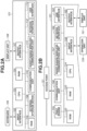
MFP 151 will be described with reference to a flowchart inFig. 9 . The flowchart according to the present embodiment is implemented by theCPU 154 reading a program related to the processing in the flowchart from theROM 152 and executing the program. - In step S901, the
CPU 154 receives from theAP 131 the trigger frame described above in step S403 inFig. 4 . In step S902, theCPU 154 determines whether to execute carrier sense. TheCPU 154 implements the processing in step S902 by referring to the information in the "CS Required"sub-field 604 inFig. 6 . If theCPU 154 determines not to execute carrier sense (NO in step S902), then in step S905, theCPU 154 transmits transmission target data to a destination apparatus via theAP 131 without executing carrier sense. - If the
CPU 154 determines to execute carrier sense (YES in step S902), then in step S903, theCPU 154 executes carrier sense. In step S904, theCPU 154 senses the energy (the power) of radio waves generated in the communication channel used in the communication with theAP 131. Then, theCPU 154 determines whether the sensed energy is greater than or equal to a threshold. If theCPU 154 determines that the energy of the radio waves generated in the communication channel is greater than or equal to the threshold (NO in step S904), theCPU 154 determines that theCPU 154 is unable to transmit data to theAP 131. Then, the processing returns to step S903. Alternatively, if theCPU 154 determines that the energy of the radio waves generated in the communication channel is greater than or equal to the threshold (NO in step S904), theCPU 154 may skip the processing of step S905 and proceed to step S906. - If the
CPU 154 determines that the power generated in the communication channel is less than the threshold (YES in step S904), theCPU 154 determines that theCPU 154 is able to transmit data to theAP 131. In step S905, theCPU 154 transmits the transmission target data to the destination apparatus via theAP 131. For example, scan data obtained by theMFP 151 reading a document, or status information regarding theMFP 151 is transmitted in step S905. TheCPU 154 transmits the transmission target data using the resource unit allocated to theMFP 151 by the "RU Allocation"sub-field 702. - In step S906, the
CPU 154 determines whether theMFP 151 is to operate as the master station for direct communication. For example, if the user instructs theMFP 151 to enable Wi-Fi Direct® and theMFP 151 is determined to operate as the group owner as a result of a negotiation (an intent value comparison) with a communication partner apparatus in the Wi-Fi Direct® mode, theCPU 154 determines that theMFP 151 is to operate as the master station for direct communication (YES in step S906). Also, if the user instructs theMFP 151 to enable the software AP mode, theCPU 154 determines that theMFP 151 is to operate as the master station for direct communication (YES in step S906). - In step S907, the
CPU 154 causes theMFP 151 to operate as the master station for direct communication. In step S908, theCPU 154 generates a trigger frame including information indicating that CS is to be executed. In step S909, theCPU 154 transmits the trigger frame to a slave station (e.g., the mobile terminal 101) connected to theCPU 154. At this time, theMFP 151 sets the information indicating that carrier sense is to be executed in the "CS Required"sub-field 604 inFig. 6 , and transmits the trigger frame illustrated inFig. 5 . TheCPU 154 also allocates the resource unit to be used by the apparatus (e.g., the mobile terminal 101) connected to theMFP 151, using the "RU Allocation"sub-field 702. In this case, themobile terminal 101 executes carrier sense and then transmits data to theMFP 151 using the allocated resource unit. For example, themobile terminal 101 transmits print data to theMFP 151 using the allocated resource unit. - While
Fig. 9 illustrates the procedure in which the processing in steps S906 to S908 is performed after the processing in steps S901 to S905, theCPU 154 may perform the processing in reverse order. In other words, after the processing in steps S906 to S908 is performed first, the processing in steps S901 to S905 may be performed. Alternatively, the processing in steps S901 to S905 and the processing in steps S906 to S908 may be performed in parallel. - If the infrastructure communication is disabled and the direct communication is enabled, the
CPU 154 may perform only the processing in steps S906 to S908. - The
MFP 151 may perform the processing in step S908 based on the information indicating whether to execute carrier sense that is included in the trigger frame transmitted from theAP 131. In other words, if theCPU 154 determines to execute CS in step S902, then in step S908, theMFP 151 generates a trigger frame including information indicating that CS is to be executed. If theCPU 154 determines not to execute CS in step S902, then in step S908, theMFP 151 generates a trigger frame including information indicating that CS is not to be executed. - According to the present embodiment, if the
MFP 151 is instructed to execute carrier sense by theAP 131, theMFP 151 transmits a trigger frame indicating that carrier sense is to be executed, to a slave station connected to theMFP 151. This enables slave stations including themobile terminal 101 to execute carrier sense and then transmit data such as print data, thereby making it possible to appropriately transmit data. - The present embodiment can also be implemented by processing of supplying a program for implementing one or more functions according to the above embodiment to a system or an apparatus via a network or a storage medium, and causing one or more processors of a computer of the system or the apparatus to read and execute the program. The present embodiment can also be implemented by a circuit (e.g., an application-specific integrated circuit (ASIC)) for implementing the one or more functions.
- According to the embodiments of the present invention, it is possible to provide a more efficient wireless communication technique.
- Embodiment(s) of the present invention can also be realized by a computer of a system or apparatus that reads out and executes computer executable instructions (e.g., one or more programs) recorded on a storage medium (which may also be referred to more fully as a 'non-transitory computer-readable storage medium') to perform the functions of one or more of the above-described embodiment(s) and/or that includes one or more circuits (e.g., application specific integrated circuit (ASIC)) for performing the functions of one or more of the above-described embodiment(s), and by a method performed by the computer of the system or apparatus by, for example, reading out and executing the computer executable instructions from the storage medium to perform the functions of one or more of the above-described embodiment(s) and/or controlling the one or more circuits to perform the functions of one or more of the above-described embodiment(s). The computer may comprise one or more processors (e.g., central processing unit (CPU), micro processing unit (MPU)) and may include a network of separate computers or separate processors to read out and execute the computer executable instructions. The computer executable instructions may be provided to the computer, for example, from a network or the storage medium. The storage medium may include, for example, one or more of a hard disk, a random-access memory (RAM), a read only memory (ROM), a storage of distributed computing systems, an optical disk (such as a compact disc (CD), digital versatile disc (DVD), or Blu-ray Disc (BD)™), a flash memory device, a memory card, and the like.
- While the present invention has been described with reference to embodiments, it is to be understood that the invention is not limited to the disclosed embodiments, but is defined by the scope of the following claims.
Claims (11)
- An image forming apparatus (151) comprising:communication control means (156) for enabling both a first mode for performing wireless communication via an external access point (131), wherein the external access point (131) is located outside the image forming apparatus, and a second mode in which wireless communication is not performed via the external access point (131) outside the image forming apparatus;reception means (154) for receiving a first trigger frame compliant with the Institute of Electrical and Electronics Engineers (IEEE) 802.11 standard from the external access point (131) while the first mode and the second mode are enabled, the first trigger frame including information regarding execution of carrier sense;first transmission means for, in a case where the first trigger frame includes information indicating that the carrier sense is to be executed, executing the carrier sense and then transmitting data;second transmission means for, in a case where the image forming apparatus (151) operates as a master station that is configured to determine a communication channel to be used in the wireless communication in the second mode while the first mode and the second mode are enabled, transmitting a second trigger frame compliant with the IEEE 802.11 standard to a slave station apparatus connected to the master station, the second trigger frame including information indicating that the carrier sense is to be executed; andprinting processing means (155) for performing printing processing on a sheet based on print data received from the slave station apparatus.
- The image forming apparatus (151) according to claim 1, further comprising reading means for scanning a document to acquire scan data,
wherein in a case where the first transmission means executes the carrier sense and determines that sensed energy is less than a threshold, the first transmission means transmits the scan data using one or more resource units allocated to the image forming apparatus (151) by the first trigger frame. - The image forming apparatus (151) according to claim 1, wherein the second trigger frame includes the information indicating that the carrier sense is to be executed and information regarding allocation of one or more resource units.
- The image forming apparatus (151) according to claim 1, wherein the maximum number of apparatuses to which resource units are allocated that is specified in the second trigger frame is equal to the maximum number of slave station apparatuses that are maintainable in parallel in the wireless communication in the second mode.
- The image forming apparatus (151) according to claim 1, wherein the image forming apparatus (151) operating as the master station maintains wireless connections with a predetermined number or less than the predetermined number of slave station apparatuses in parallel in the second mode.
- The image forming apparatus (151) according to claim 1, wherein the wireless communication in the first mode and the wireless communication in the second mode are performed using the same communication channel.
- The image forming apparatus (151) according to claim 1, wherein the wireless communication in the first mode and the wireless communication in the second mode are performed using different communication channels.
- The image forming apparatus (151) according to claim 1, wherein the image forming apparatus performs wireless communication using a frequency band selected from among 2.4 GHz, 5 GHz, and 6 GHz.
- A method for performing a print job by an image forming apparatus (151), the method comprising:setting a first mode for performing wireless communication via an external access point (131), wherein the external access point (131) is located outside the image forming apparatus, and a second mode in which wireless communication is not performed via the external access point (131) outside the image forming apparatus;receiving a first trigger frame compliant with the Institute of Electrical and Electronics Engineers (IEEE) 802.11 standard from the external access point (131) while the first mode and the second mode are enabled, the first trigger frame including information regarding execution of carrier sense;transmitting via a first transmission means, in a case where the first trigger frame includes information indicating that the carrier sense is to be executed, data after executing the carrier sense;transmitting via a second transmission means, in a case where the image forming apparatus (151) operates as a master station that is configured to determine a communication channel to be used in the wireless communication in the second mode while the first mode and the second mode are enabled, a second trigger frame compliant with the IEEE 802.11 standard to a slave station apparatus connected to the master station, the second trigger frame including information indicating that the carrier sense is to be executed; andperforming printing processing on a sheet based on print data received from the slave station apparatus.
- A computer program comprising instructions which, when executed by an image forming apparatus, cause the image forming apparatus to perform the method of claim 9.
- A computer-readable medium having stored thereon the program of claim 10.
Applications Claiming Priority (1)
| Application Number | Priority Date | Filing Date | Title |
|---|---|---|---|
| JP2022031122A JP7562587B2 (en) | 2022-03-01 | 2022-03-01 | COMMUNICATION DEVICE, ITS CONTROL METHOD, PRINTING DEVICE, ITS CONTROL METHOD, PROGRAM, AND STORAGE MEDIUM |
Publications (1)
| Publication Number | Publication Date |
|---|---|
| EP4239995A1 true EP4239995A1 (en) | 2023-09-06 |
Family
ID=85384536
Family Applications (1)
| Application Number | Title | Priority Date | Filing Date |
|---|---|---|---|
| EP23158843.5A Pending EP4239995A1 (en) | 2022-03-01 | 2023-02-27 | Image forming apparatus, method, computer program, and computer-readable medium |
Country Status (5)
| Country | Link |
|---|---|
| US (2) | US11853632B2 (en) |
| EP (1) | EP4239995A1 (en) |
| JP (1) | JP7562587B2 (en) |
| KR (1) | KR20230129299A (en) |
| CN (1) | CN116709008A (en) |
Families Citing this family (2)
| Publication number | Priority date | Publication date | Assignee | Title |
|---|---|---|---|---|
| CN114552090B (en) * | 2020-11-26 | 2023-09-05 | 比亚迪股份有限公司 | Battery modules and batteries |
| JP2024014514A (en) * | 2022-07-22 | 2024-02-01 | キヤノン株式会社 | image forming device |
Citations (3)
| Publication number | Priority date | Publication date | Assignee | Title |
|---|---|---|---|---|
| JP2012019487A (en) | 2010-07-09 | 2012-01-26 | Canon Inc | Communication device and control method |
| WO2021029555A1 (en) * | 2019-08-12 | 2021-02-18 | 엘지전자 주식회사 | Transmission and reception of signal in multi-ap system |
| US20210405940A1 (en) * | 2020-06-29 | 2021-12-30 | Canon Kabushiki Kaisha | Communication apparatus |
Family Cites Families (13)
| Publication number | Priority date | Publication date | Assignee | Title |
|---|---|---|---|---|
| JP6242241B2 (en) * | 2013-04-26 | 2017-12-06 | キヤノン株式会社 | Printing apparatus, communication apparatus, and program |
| JP6216149B2 (en) * | 2013-04-26 | 2017-10-18 | キヤノン株式会社 | COMMUNICATION DEVICE, COMMUNICATION METHOD, AND PROGRAM |
| EP3157300B1 (en) * | 2015-07-31 | 2021-03-31 | Lg Electronics Inc. | Method for transmitting data in wireless communication system and apparatus therefor |
| JP6503968B2 (en) * | 2015-08-05 | 2019-04-24 | ブラザー工業株式会社 | Communication device and computer program for communication device |
| JP6693218B2 (en) * | 2016-03-25 | 2020-05-13 | ブラザー工業株式会社 | Program of near field communication device, program of mobile device, and system including these devices |
| JP6676469B2 (en) * | 2016-05-20 | 2020-04-08 | キヤノン株式会社 | Communication device, control method therefor, and program |
| SG11201810184QA (en) * | 2016-07-22 | 2018-12-28 | Panasonic Ip Corp America | Transmission appratus and transmission method |
| JP6932586B2 (en) * | 2017-09-14 | 2021-09-08 | キヤノン株式会社 | Information processing equipment, its control method, and programs |
| JP7112203B2 (en) * | 2018-01-31 | 2022-08-03 | キヤノン株式会社 | Communication device, control method, and program |
| JP7199825B2 (en) * | 2018-04-26 | 2023-01-06 | キヤノン株式会社 | Communication system, control method, and program |
| US11632797B2 (en) * | 2018-07-26 | 2023-04-18 | Lg Electronics Inc. | Method and apparatus for receiving UL data in wireless LAN system |
| SG10201906255QA (en) * | 2019-07-04 | 2021-02-25 | Panasonic Ip Corp America | Communication apparatus and communication method for enhanced direct link communication |
| CN115918221A (en) * | 2020-06-29 | 2023-04-04 | Lg电子株式会社 | P2P Transmission Method in Wireless LAN System |
-
2022
- 2022-03-01 JP JP2022031122A patent/JP7562587B2/en active Active
-
2023
- 2023-02-16 KR KR1020230020417A patent/KR20230129299A/en active Pending
- 2023-02-23 CN CN202310156510.7A patent/CN116709008A/en active Pending
- 2023-02-27 US US18/174,778 patent/US11853632B2/en active Active
- 2023-02-27 EP EP23158843.5A patent/EP4239995A1/en active Pending
- 2023-11-14 US US18/508,773 patent/US12307148B2/en active Active
Patent Citations (3)
| Publication number | Priority date | Publication date | Assignee | Title |
|---|---|---|---|---|
| JP2012019487A (en) | 2010-07-09 | 2012-01-26 | Canon Inc | Communication device and control method |
| WO2021029555A1 (en) * | 2019-08-12 | 2021-02-18 | 엘지전자 주식회사 | Transmission and reception of signal in multi-ap system |
| US20210405940A1 (en) * | 2020-06-29 | 2021-12-30 | Canon Kabushiki Kaisha | Communication apparatus |
Also Published As
| Publication number | Publication date |
|---|---|
| US12307148B2 (en) | 2025-05-20 |
| US20230280960A1 (en) | 2023-09-07 |
| JP2023127368A (en) | 2023-09-13 |
| US20240086132A1 (en) | 2024-03-14 |
| KR20230129299A (en) | 2023-09-08 |
| JP7562587B2 (en) | 2024-10-07 |
| CN116709008A (en) | 2023-09-05 |
| US11853632B2 (en) | 2023-12-26 |
Similar Documents
| Publication | Publication Date | Title |
|---|---|---|
| US20260029972A1 (en) | Image forming apparatus, method, and medium | |
| US12307148B2 (en) | Image forming apparatus for determining a communication channel to be used in a wireless communication | |
| US20240188149A1 (en) | Communication apparatus | |
| US20240419376A1 (en) | Image forming apparatus | |
| US12307139B2 (en) | Image forming apparatus | |
| US20240283876A1 (en) | Communication apparatus | |
| EP4518265A1 (en) | Image formation device | |
| US20240323766A1 (en) | Communication apparatus | |
| EP4561252A1 (en) | Image formation device | |
| US12260136B2 (en) | Communication apparatus performing communication through orthogonal frequency division multiple access and method for controlling communication apparatus | |
| US20240204930A1 (en) | Communication apparatus |
Legal Events
| Date | Code | Title | Description |
|---|---|---|---|
| PUAI | Public reference made under article 153(3) epc to a published international application that has entered the european phase |
Free format text: ORIGINAL CODE: 0009012 |
|
| STAA | Information on the status of an ep patent application or granted ep patent |
Free format text: STATUS: THE APPLICATION HAS BEEN PUBLISHED |
|
| AK | Designated contracting states |
Kind code of ref document: A1 Designated state(s): AL AT BE BG CH CY CZ DE DK EE ES FI FR GB GR HR HU IE IS IT LI LT LU LV MC ME MK MT NL NO PL PT RO RS SE SI SK SM TR |
|
| STAA | Information on the status of an ep patent application or granted ep patent |
Free format text: STATUS: REQUEST FOR EXAMINATION WAS MADE |
|
| 17P | Request for examination filed |
Effective date: 20240306 |
|
| RBV | Designated contracting states (corrected) |
Designated state(s): AL AT BE BG CH CY CZ DE DK EE ES FI FR GB GR HR HU IE IS IT LI LT LU LV MC ME MK MT NL NO PL PT RO RS SE SI SK SM TR |
|
| GRAP | Despatch of communication of intention to grant a patent |
Free format text: ORIGINAL CODE: EPIDOSNIGR1 |
|
| STAA | Information on the status of an ep patent application or granted ep patent |
Free format text: STATUS: GRANT OF PATENT IS INTENDED |
|
| INTG | Intention to grant announced |
Effective date: 20260115 |
|
| GRAS | Grant fee paid |
Free format text: ORIGINAL CODE: EPIDOSNIGR3 |
|
| GRAA | (expected) grant |
Free format text: ORIGINAL CODE: 0009210 |
|
| STAA | Information on the status of an ep patent application or granted ep patent |
Free format text: STATUS: THE PATENT HAS BEEN GRANTED |