EP4239863A1 - Work machine - Google Patents
Work machine Download PDFInfo
- Publication number
- EP4239863A1 EP4239863A1 EP21886082.3A EP21886082A EP4239863A1 EP 4239863 A1 EP4239863 A1 EP 4239863A1 EP 21886082 A EP21886082 A EP 21886082A EP 4239863 A1 EP4239863 A1 EP 4239863A1
- Authority
- EP
- European Patent Office
- Prior art keywords
- teeth
- wound around
- circuit board
- coils
- winding
- Prior art date
- Legal status (The legal status is an assumption and is not a legal conclusion. Google has not performed a legal analysis and makes no representation as to the accuracy of the status listed.)
- Pending
Links
Images




Classifications
-
- H—ELECTRICITY
- H02—GENERATION; CONVERSION OR DISTRIBUTION OF ELECTRIC POWER
- H02K—DYNAMO-ELECTRIC MACHINES
- H02K3/00—Details of windings
- H02K3/04—Windings characterised by the conductor shape, form or construction, e.g. with bar conductors
- H02K3/28—Layout of windings or of connections between windings
-
- H—ELECTRICITY
- H02—GENERATION; CONVERSION OR DISTRIBUTION OF ELECTRIC POWER
- H02K—DYNAMO-ELECTRIC MACHINES
- H02K7/00—Arrangements for handling mechanical energy structurally associated with dynamo-electric machines, e.g. structural association with mechanical driving motors or auxiliary dynamo-electric machines
- H02K7/14—Structural association with mechanical loads, e.g. with hand-held machine tools or fans
- H02K7/145—Hand-held machine tool
-
- H—ELECTRICITY
- H02—GENERATION; CONVERSION OR DISTRIBUTION OF ELECTRIC POWER
- H02K—DYNAMO-ELECTRIC MACHINES
- H02K11/00—Structural association of dynamo-electric machines with electric components or with devices for shielding, monitoring or protection
- H02K11/30—Structural association with control circuits or drive circuits
- H02K11/33—Drive circuits, e.g. power electronics
-
- H—ELECTRICITY
- H02—GENERATION; CONVERSION OR DISTRIBUTION OF ELECTRIC POWER
- H02K—DYNAMO-ELECTRIC MACHINES
- H02K3/00—Details of windings
- H02K3/46—Fastening of windings on the stator or rotor structure
- H02K3/52—Fastening salient pole windings or connections thereto
- H02K3/521—Fastening salient pole windings or connections thereto applicable to stators only
- H02K3/522—Fastening salient pole windings or connections thereto applicable to stators only for generally annular cores with salient poles
-
- H—ELECTRICITY
- H02—GENERATION; CONVERSION OR DISTRIBUTION OF ELECTRIC POWER
- H02K—DYNAMO-ELECTRIC MACHINES
- H02K2203/00—Specific aspects not provided for in the other groups of this subclass relating to the windings
- H02K2203/03—Machines characterised by the wiring boards, i.e. printed circuit boards or similar structures for connecting the winding terminations
-
- H—ELECTRICITY
- H02—GENERATION; CONVERSION OR DISTRIBUTION OF ELECTRIC POWER
- H02K—DYNAMO-ELECTRIC MACHINES
- H02K2211/00—Specific aspects not provided for in the other groups of this subclass relating to measuring or protective devices or electric components
- H02K2211/03—Machines characterised by circuit boards, e.g. pcb
Definitions
- the present invention relates to a work machine having a plurality of coils on its stator.
- Patent Literature 1 listed below describes an electric tool in which multiple phases are delta-connected and multiple coils of each phase are connected in parallel, that is, the so-called delta connection parallel winding, to improve the performance of the motor.
- the present invention has been made in recognition of such a situation, and an object thereof is to provide a work machine in which the structure of the motor (the connection structure of the motor coils) is devised to improve the assembling efficiency, and moreover, to provide a work machine that facilitates the connection of motor coils.
- the work machine includes a brushless motor having a stator having a plurality of teeth, a rotor rotating with respect to the stator, and a winding having coils wound around each of the plurality of teeth; and an output portion driven by the brushless motor.
- the work machine further includes: a short-circuit portion having a first short-circuit portion that connects coils wound around teeth that are adjacent and a second short-circuit portion that connects coils wound around teeth that are non-adjacent. According to this aspect, it is possible to easily connect a plurality of coils. Thus, it is possible to easily assemble a motor. Moreover, the degree of freedom in design can be improved.
- This work machine includes a brushless motor having a stator having a plurality of teeth, a rotor rotating with respect to the stator, and a winding wound around the stator; a circuit board to which the winding is connected; and an output portion driven by the brushless motor.
- the winding has a plurality of coils forming mutually different phases and a plurality of coils forming the same phase.
- the plurality of coils forming mutually different phases and/or the plurality of coils forming the same phase are connected by a short-circuit portion provided on the circuit board. According to this aspect, it is possible to easily connect a plurality of coils. Thus, it is possible to easily assemble a motor. Moreover, the degree of freedom in design can be improved.
- a circuit board to which the winding is connected may be provided, and the short-circuit portion may be a pattern formed on the circuit board. Accordingly, there is no need to provide a member dedicated to short-circuiting.
- a plurality of the coils of different phases may be delta-connected, and a plurality of the coils of the same phase may be connected in parallel. Accordingly, a high output can be obtained without complicating the connection of the coils.
- the winding may be sequentially wound around teeth that are adjacent in the plurality of teeth. Accordingly, the connecting wire can be simplified, and the connection can be easily performed.
- a first pattern for connecting coils wound around the teeth that are non-adjacent or that face each other may be formed in a first region of the circuit board; a second pattern for connecting coils wound around the teeth that are non-adjacent or that face each other may be formed in a second region of the circuit board; and a third pattern for connecting coils wound around the teeth that are non-adjacent or that face each other may be formed in a third region of the circuit board.
- the winding is sequentially wound around teeth that are adjacent in one direction in the plurality of teeth, then wound around teeth that face each other in the plurality of teeth, and wound around teeth that are adjacent in the other direction. Accordingly, the short-circuit portion may be made smaller, and for example, a circuit board of two layers can be realized.
- the winding may be wound around teeth that face each other, sequentially wound around teeth that are adjacent in one direction, wound around teeth that face each other, and wound around teeth that are adjacent in the other direction. Accordingly, the short-circuit portion may be made smaller, and for example, a circuit board of two layers can be realized.
- a first pattern for connecting the coils wound around the teeth that are adjacent may be formed a the first region of the circuit board; a second pattern for connecting coils wound around teeth that are non-adjacent may be formed in a second region of the circuit board; and a third pattern for connecting coils wound around teeth that are non-adjacent may be formed in a third region of the circuit board.
- the winding may be wound around every other teeth in one direction in the plurality of teeth, wound around teeth that face each other, and wound around every other teeth in the other direction. Accordingly, the short-circuit portion may be made smaller, and for example, a circuit board of one layer or two layers can be realized.
- the stator has a plurality of teeth around which the winding is wound, and the winding is wound around teeth that face each other in the plurality of teeth, wound around every other teeth in one direction, wound around teeth that face each other, and wound around every other teeth in the other direction. Accordingly, the short-circuit portion may be made smaller, and for example, a circuit board of one layer or two layers can be realized.
- a first pattern for connecting coils wound around the teeth that are adjacent may be formed in a first region of the circuit board; a second pattern for connecting coils wound around another of the teeth that are adjacent may be formed in a second region of the circuit board; and a third pattern for connecting coils wound around yet another of the teeth that are adjacent may be formed in the third region of the circuit board.
- Yet another aspect of the present invention is a work machine.
- This work machine includes a brushless motor having a stator having a plurality of teeth, a rotor rotating with respect to the stator, and a winding wound around the stator; a circuit board to which the winding is connected; and an output portion driven by the brushless motor.
- the winding includes a plurality of delta-connected coils forming mutually different phases and a plurality of parallel-connected coils forming the same phase.
- the plurality of delta-connected coils and the plurality of parallel-connected coils are connected by a pattern formed on the circuit board. Accordingly, it is possible to realize delta connection parallel winding with a simple configuration while suppressing an increase in the number of components.
- the present embodiment relates to a work machine 1.
- the work machine 1 is a saber saw.
- Figure 1 defines front, rear, and up-down directions of the work machine 1 that are orthogonal to each other.
- the work machine 1 includes a housing 3 and a front cover 4 made of, for example, a resin molding.
- the front cover 4 is connected and fixed to a front end portion of the housing 3.
- the housing 3 has a motor accommodation portion 3a that accommodates a motor 6, and a handle portion 3b that may be gripped by an operator.
- a control board 7 is provided below the motor 6 in the motor accommodation portion 3a.
- a trigger switch 8 is provided on an upper portion of the handle portion 3b to be operated by an operator to instruct the motor 6 to be driven or stopped.
- a battery pack 9 is detachably connected to a lower end portion of the handle portion 3b. The work machine 1 operates with power supplied from the battery pack 9.
- the motor 6 is a brushless motor, and is held in the motor accommodation portion 3a of the housing 3 such that its rotating shaft is parallel to the front-rear direction.
- the power of the motor 6 is transmitted by a transmission mechanism 50 to a saw blade 5 as an output portion (tip tool).
- the transmission mechanism 50 has a reciprocating drive mechanism that converts the rotation of the motor 6 into a reciprocating motion in the front-rear direction and transmits it to the saw blade 5, and a swinging mechanism that swings the saw blade 5 in the up-down direction by the rotation of the motor 6.
- An operator may switch between enabling and disabling the orbital mode, in which the swing mechanism is operated to swing saw blade 5 in the up-down direction to cut (truncate) the material, using a change lever (not shown).
- at least one of the saw blade 5 and the transmission mechanism corresponds to the output portion.
- the motor 6 includes a cylindrical rotor core 6b that is provided around an output shaft 6a and rotates together with the output shaft 6a; four rotor magnets (permanent magnets) 6c inserted and held in the rotor core 6b at intervals of 90 degrees in the circumferential direction; a stator core 6e provided to surround outer periphery of the rotor core 6b; and six stator coils 6h ( Figures 3 and 4 ) provided in the stator core 6e.
- the rotor core 6b and the rotor magnet 6c constitute the rotor of the motor 6.
- the stator core 6e constitutes the stator of the motor 6.
- the six stator coils 6h constitute the windings of the motor 6. In Figures 5 and 6 , the illustration of the stator coils 6h is omitted.
- the stator core 6e includes a cylindrical (annular) yoke portion 6f, and six teeth 6g protruding radially inward from the yoke portion 6f. Each of the teeth 6g is provided with the stator coil 6h. That is, each of the teeth 6g forms a winding slot. As shown in (A) of Figure 7 and the like, the stator coil 6h has U-phase stator coils U1, U2; V-phase stator coils V1, V2; and W-phase stator coils W1, W2.
- the stator coil 6h is arranged in the order of the V-phase stator coil V1, the U-phase stator coil U2, the W-phase stator coil W1, the V-phase stator coil V2, the U-phase stator coil U1, and the W-phase stator coil W2 in the direction around the axis of the motor 6.
- an insulator 6i is provided on the rear end surface of the stator core 6e.
- the insulator 6i is, for example, a resin molding.
- the insulator 6i holds six fusing terminals 6j in the circumferential direction at equal angular intervals.
- Each of the fusing terminals 6j has a rearwardly extending protruding portion 6k and a hooking portion 6m for hooking an end portion of each stator coil 6h.
- Each of the fusing terminals 6j is electrically connected to an end portion of each stator coil 6h.
- a circuit board 6n is connected behind the insulator 6i.
- the circuit board 6n is fixed to the insulator 6i by screws or the like so as to be perpendicular to the front-rear direction.
- the circuit board 6n has six through holes 6p at equal angular intervals in the circumferential direction.
- the protruding portion 6k of each of the fusing terminals 6j passes through each of the through holes 6p and is electrically connected to the circuit board 6n by soldering or the like.
- An insulator 6r is provided on a front end surface of the stator core 6e.
- FIG. 7 to 11 The winding form of the motor 6 will be described with reference to Figures 7 to 11 .
- points u1 and u2 are winding start side end portions of the U-phase stator coils U1 and U2, respectively.
- Points v1 and v2 are winding start side end portions of the V-phase stator coils V1 and V2, respectively.
- Points w1 and w2 are winding start side end portions of the W-phase stator coils W1 and W2, respectively.
- the stator coil 6h is a delta connection parallel winding.
- the U-phase stator coils U1 and U2, the V-phase stator coils V1 and V2, and the W-phase stator coils W1 and W2 are delta-connected, and the U-phase stator coils U1 and U2 are connected in parallel, the V-phase stator coils V1 and V2 are connected in parallel, and the W-phase stator coils W1 and W2 are connected in parallel.
- five winding forms of delta connection parallel winding are shown.
- FIG. 7 (Winding Form 1)
- FIG. 7 (A)-(F) of Figure 7 relate to a winding form 1.
- A) of Figure 7 is a schematic diagram showing the wiring order of the stator coils (U1, U2, V1, V2, W1, W2) in the winding form 1.
- B) of Figure 7 is a schematic diagram showing the connection relationship of the end portions (u1, u2, v1, v2, w1, w2) of the stator coils on the circuit board 6n in the winding form 1.
- Figure 7 (C) is a schematic diagram showing the stator coils and their interconnection relationship when the stator core 6e is unfolded and viewed in the winding form 1.
- D)-(F) of Figure 7 are schematic diagrams showing the conductor patterns of the circuit board 6n in the winding form 1 by hatching.
- windings are sequentially wound around teeth 6g that are adjacent in the six teeth 6g, and are wound in order around the U-phase stator coils U1, the V-phase stator coil V2, the W-phase stator coil W1, the U-phase stator coil U2, the V-phase stator coil V1, and the W-phase stator coil W2.
- the circuit board 6n is formed with a first conductor pattern 61, a second conductor pattern 62, and a third conductor pattern 63, each of which is made of, for example, copper foil that functions as a short-circuit portion.
- the first conductor pattern 61 electrically connects one ends (u1, u2) of the U-phase stator coils U1, U2 wound around teeth 6g that face each other with the central axis of the motor 6 interposed therebetween.
- the second conductor pattern 62 electrically connects one ends (v1, v2) of the V-phase stator coils V1 and V2 wound around teeth 6g that face each other with the central axis of the motor 6 (hereinafter also referred to as the "central axis") interposed therebetween.
- the third conductor pattern 63 electrically connects one ends (w1, w2) of the W-phase stator coils W 1, W2 wound around teeth 6g that face each other with the central axis of the motor 6 interposed therebetween.
- a first region where the first conductor pattern 61 is formed, a second region where the second conductor pattern 62 is formed, and a third region where the third conductor pattern 63 is formed partially overlap each other when viewed from the direction perpendicular to the circuit board 6n.
- the first conductor pattern 61, the second conductor pattern 62, and the third conductor pattern 63 are provided in different layers of the circuit board 6n.
- the circuit board 6n has at least three layers on which conductor patterns may be formed.
- FIG. 8 (Winding Form 2)
- FIG. 8 (A)-(F) of Figure 8 relate to a winding form 2.
- A) of Figure 8 is a schematic diagram showing the wiring order of the stator coils (U1, U2, V1, V2, W1, W2) in the winding form 2.
- B) of Figure 8 is a schematic diagram showing the connection relationship of the end portions (u1, u2, v1, v2, w1, w2) of the stator coils on the circuit board 6n in the winding form 2.
- Figure 8 (C) is a schematic diagram showing the stator coils and their interconnection relationship when the stator core 6e is unfolded and viewed in the winding form 2.
- D)-(F) of Figure 8 are schematic diagrams showing the conductor patterns of the circuit board 6n in the winding form 2 by hatching.
- windings are sequentially wound around teeth 6g that are adjacent in one direction in the six teeth 6g, then wound around teeth 6g that face each other with the central axis interposed therebetween, and wound around teeth that are adjacent in the other direction, thereby winding the U-phase stator coils U1, the V-phase stator coils V2, the W-phase stator coils W1, the W-phase stator coils W2, the V-phase stator coils V1, and the U-phase stator coils U2 in order.
- the circuit board 6n is formed with a first conductor pattern 64, a second conductor pattern 65, and a third conductor pattern 66, each of which is made of, for example, copper foil that functions as a short-circuit portion.
- the first conductor pattern 64 is an example of a first short-circuit portion, and electrically connects one ends (u1, w2) of the U-phase stator coil U1 and the W-phase stator coil W2 wound around teeth 6g that are adjacent.
- the second conductor pattern 65 is an example of a second short-circuit portion, and electrically connects one ends (v1, w1) of the V-phase stator coil V1 and the W-phase stator coil W1 wound around teeth 6g that are non-adjacent.
- the third conductor pattern 66 is an example of a second short-circuit portion, and electrically connects one ends (u2, w2) of the U-phase stator coil U2 and the W-phase stator coil W2 wound around teeth 6g that are non-adjacent.
- the second region where the second conductor pattern 65 is formed and the third region where the third conductor pattern 66 is formed partially overlap each other when viewed from the direction perpendicular to the circuit board 6n.
- the first region where the first conductor pattern 64 is formed does not overlap the second region and the third region when viewed from the same direction.
- FIG. 9 (Winding Form 3)
- FIG. 9 (A)-(F) of Figure 9 relate to a winding form 3.
- A) of Figure 9 is a schematic diagram showing the wiring order of the stator coils (U1, U2, V1, V2, W1, W2) in the winding form 3.
- B) of Figure 9 is a schematic diagram showing the connection relationship of the end portions (u1, u2, v1, v2, w1, w2) of the stator coils on the circuit board 6n in the winding form 3.
- Figure 9 (C) is a schematic diagram showing the stator coils and their interconnection relationship when the stator core 6e is unfolded and viewed in the winding form 3.
- D)-(F) of Figure 9 are schematic diagrams showing the conductor patterns of the circuit board 6n in the winding form 3 by hatching.
- the windings are wound around teeth 6g that face each other, sequentially wound around teeth 6g that are adjacent in one direction, wound around teeth 6g that face each other, and wound around teeth 6g that are adjacent in the other direction, thereby winding the U-phase stator coil U1, the U-phase stator coil U2, the W-phase stator coil W1, the V-phase stator coil V2, the V-phase stator coil V1 and the W-phase stator coil W2 in order.
- the circuit board 6n is formed with a first conductor pattern 67, a second conductor pattern 68, and a third conductor pattern 69, each of which is made of, for example, copper foil that functions as a short-circuit portion.
- the first conductor pattern 67 is an example of a first short-circuit portion, and electrically connects one ends (u2, v1) of the U-phase stator coil U2 and the V-phase stator coil V1 wound around teeth 6g that are adjacent.
- the second conductor pattern 68 is an example of a second short-circuit portion, and electrically connects one ends (v2, w2) of the V-phase stator coil V2 and the W-phase stator coil W2 wound around teeth 6 that are non-adjacent.
- the third conductor pattern 69 is an example of a second short-circuit portion, and electrically connects one ends (u1, w1) of the U-phase stator coil U1 and the W-phase stator coil W1 wound around teeth 6 that are non-adjacent.
- the second region where the second conductor pattern 68 is formed and the third region where the third conductor pattern 69 is formed partially overlap each other when viewed from the direction perpendicular to the circuit board 6n.
- the first region where the first conductor pattern 67 is formed does not overlap the second region and the third region when viewed from the same direction.
- the first conductor pattern 67, the second conductor pattern 68, and the third conductor pattern 69 are provided in different layers of the circuit board 6n in (D)-(F) of Figure 9
- the second conductor pattern 68 and the third conductor pattern 69 may be provided in different layers of the circuit board 6n, and the first conductor pattern 67 may be provided in the same layer as the second conductor pattern 68 or the third conductor pattern 69.
- the circuit board 6n in this case only needs to have at least two layers on which conductor patterns may be formed.
- FIG. 4 (Winding Form 4)
- FIG. 10 (A)-(F) of Figure 10 relate to a winding form 4.
- A) of Figure 10 is a schematic diagram showing the wiring order of the stator coils (U1, U2, V1, V2, W1, W2) in the winding form 4.
- B) of Figure 10 is a schematic diagram showing the connection relationship of the end portions (u1, u2, v1, v2, w1, w2) of the stator coils on the circuit board 6n in the winding form 4.
- Figure 10 (C) is a schematic diagram showing the stator coils and their interconnection relationship when the stator core 6e is unfolded and viewed in the winding form 4.
- Figure (D)-(F) of Figure 10 are schematic diagrams showing the conductor patterns of the circuit board 6n in the winding form 4 by hatching.
- the windings are wound around every other teeth 6g in one direction in the six teeth 6g, wound around teeth 6g that face each other, and wound around every other teeth 6g in the other direction, thereby winding the U-phase stator coil U1, the V-phase stator coil V1, the W-phase stator coil W1, the W-phase stator coil W2, the V-phase stator coil V2, and the U-phase stator coil U2 in order.
- the circuit board 6n is formed with a first conductor pattern 70, a second conductor pattern 71, and a third conductor pattern 72, each of which is made of, for example, copper foil that functions as a short-circuit portion.
- the first conductor pattern 70 electrically connects one ends (u1, w2) of the U-phase stator coil U1 and the W-phase stator coil W2 wound around teeth 6g that are adjacent.
- the second conductor pattern 71 electrically connects one ends (u2, v1) of the U-phase stator coil U2 and the V-phase stator coil V1 wound around teeth 6g that are adjacent.
- the third conductor pattern 72 electrically connects one ends (v2, w1) of the V-phase stator coil V2 and the W-phase stator coil W1 wound around teeth 6g that are adjacent.
- the first region where the first conductor pattern 70 is formed, the second region where the second conductor pattern 71 is formed, and the third region where the third conductor pattern 72 is formed are not overlapped when viewed from the direction perpendicular to the circuit board 6n.
- the first conductor pattern 70, the second conductor pattern 71, and the third conductor pattern 72 are provided in different layers of the circuit board 6n, but the first conductor pattern 70, the second conductor pattern 71, and the third conductor pattern 72 may be provided in the same layer of the circuit board 6n.
- two of the first conductor pattern 70, the second conductor pattern 71, and the third conductor pattern 72 may be provided in the same layer, and the remaining one may be provided in another layer. That is, the circuit board 6n only needs to have at least one layer on which a conductor pattern may be formed.
- FIG. 5 (Winding Form 5)
- FIG. 5 (A)-(F) of Figure 11 relate to a winding form 5.
- FIG. 1 (A) of Figure 11 is a schematic diagram showing the wiring order of the stator coils (U1, U2, V1, V2, W1, W2) in the winding form 5.
- (B) of Figure 11 is a schematic diagram showing the connection relationship of the end portions (u1, u2, v1, v2, w1, w2) of the stator coils on the circuit board 6n in the winding form 5.
- Figure 11 (C) is a schematic diagram showing the stator coils and their interconnection relationship when the stator core 6e is unfolded and viewed in the winding form 5.
- FIG.D)-(F) of Figure 11 are schematic diagrams showing the conductor patterns of the circuit board 6n in the winding form 5 by hatching.
- the windings are wound around teeth 6g that face each other in the six teeth 6g, wound around every other teeth 6g in one direction, wound around teeth 6g that face each other, and wound around every other teeth 6g in the other direction, thereby winding the U-phase stator coil U1, the U-phase stator coil U2, the W-phase stator coil W2, the V-phase stator coil V2, the V-phase stator coil V1, and the W-phase stator coil W1 in order.
- the circuit board 6n is formed with a first conductor pattern 73, a second conductor pattern 74, and a third conductor pattern 75, each of which is made of, for example, copper foil that functions as a short-circuit portion.
- the first conductor pattern 73 electrically connects one ends (u1, w2) of the U-phase stator coil U1 and the W-phase stator coil W2 wound around teeth 6g that are adjacent.
- the second conductor pattern 74 electrically connects one ends (u2, v1) of the U-phase stator coil U2 and the V-phase stator coil V1 wound around teeth 6g that are adjacent.
- the third conductor pattern 75 electrically connects one ends (v2, w1) of the V-phase stator coil V2 and the W-phase stator coil W1 wound around teeth 6g that are adjacent.
- the first region where the first conductor pattern 73 is formed, the second region where the second conductor pattern 74 is formed, and the third region where the third conductor pattern 75 is formed are not overlapped when viewed from the direction perpendicular to the circuit board 6n.
- the first conductor pattern 73, the second conductor pattern 74, and the third conductor pattern 75 are provided in different layers of the circuit board 6n, the first conductor pattern 73, the second conductor pattern 74, and the third conductor pattern 75 may be provided in the same layer of the circuit board 6n.
- the circuit board 6n only needs to have at least one layer on which a conductor pattern may be formed. Further, in any winding form, the circuit board 6n may be further provided with a layer for arranging a rotation detection element (a magnetic sensor 43 to be described later) for detecting rotation of the motor 6, or a layer on which a conductor pattern is formed may be used.
- the rotation detection element is preferably provided in a layer facing the motor 6 (rotor).
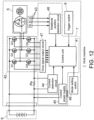
- FIG 12 is a circuit block diagram of the work machine 1.
- An inverter circuit 42 is composed of switching elements Q1 to Q6 such as FETs and IGBTs connected in a three-phase bridge.
- the magnetic sensor 43 such as a Hall IC is arranged near the motor 6 and outputs a signal corresponding to the rotational position of the motor 6.
- the control board 7 is provided with a control unit 41, a current detection circuit 44, a control power supply circuit 45, a drive signal output circuit 47, and a rotational position detection circuit 48.
- the current detection circuit 44 detects the current of the motor 6 from the voltage at both ends of the resistor Rs provided in the current path of the motor 6 and transmits it to the control unit 41.
- the control power supply circuit 45 converts the voltage of the battery pack 9 into power supply voltage for the control unit 41 and the like, and supplies it to the control unit 41 and the like.
- the drive signal output circuit 47 outputs drive signals to switching elements Q1 to Q6 of the inverter circuit 42 under the control of the control unit 41.
- the rotational position detection circuit 48 detects the rotational position of the motor 6 from the output signal of the magnetic sensor 43 and transmits it to the control unit 41.
- the control unit 41 includes a microcontroller and the like, and controls the inverter circuit 42 through the drive signal output circuit 47 in the mode set by a mode setting switch 46 according to the operation of the trigger switch 8, so as to control the driving of the motor 6.
- the work machine 1 is not limited to a saver saw, and may be of other types having a brushless motor.
- the work machine 1 is not limited to a cordless type that operates on power from the battery pack 9, and may be a corded type that operates on power supplied from an external AC power supply.
- the number of the teeth 6g and the stator coils 6h, and the number of the rotor magnets, and the like are not limited to the specific numbers exemplified in the embodiments and are arbitrary.
Landscapes
- Engineering & Computer Science (AREA)
- Power Engineering (AREA)
- Microelectronics & Electronic Packaging (AREA)
- Windings For Motors And Generators (AREA)
- Portable Power Tools In General (AREA)
Abstract
Description
- The present invention relates to a work machine having a plurality of coils on its stator.
- Work machines such as power tools are becoming more powerful. Devising the wiring method of the motor coils contributes to higher output.
Patent Literature 1 listed below describes an electric tool in which multiple phases are delta-connected and multiple coils of each phase are connected in parallel, that is, the so-called delta connection parallel winding, to improve the performance of the motor. - [Patent Literature 1]
JP2016-179536 - Although it is possible to improve the performance of a motor by devising the wiring method of motor coils, there is a problem that the structure of the motor, for example, the connection structure of the motor coils becomes complicated.
- The present invention has been made in recognition of such a situation, and an object thereof is to provide a work machine in which the structure of the motor (the connection structure of the motor coils) is devised to improve the assembling efficiency, and moreover, to provide a work machine that facilitates the connection of motor coils.
- Solution to Problem
- One aspect of the present invention is a work machine. The work machine includes a brushless motor having a stator having a plurality of teeth, a rotor rotating with respect to the stator, and a winding having coils wound around each of the plurality of teeth; and an output portion driven by the brushless motor. The work machine further includes: a short-circuit portion having a first short-circuit portion that connects coils wound around teeth that are adjacent and a second short-circuit portion that connects coils wound around teeth that are non-adjacent. According to this aspect, it is possible to easily connect a plurality of coils. Thus, it is possible to easily assemble a motor. Moreover, the degree of freedom in design can be improved.
- Another aspect of the present invention is a work machine. This work machine includes a brushless motor having a stator having a plurality of teeth, a rotor rotating with respect to the stator, and a winding wound around the stator; a circuit board to which the winding is connected; and an output portion driven by the brushless motor. The winding has a plurality of coils forming mutually different phases and a plurality of coils forming the same phase. The plurality of coils forming mutually different phases and/or the plurality of coils forming the same phase are connected by a short-circuit portion provided on the circuit board. According to this aspect, it is possible to easily connect a plurality of coils. Thus, it is possible to easily assemble a motor. Moreover, the degree of freedom in design can be improved.
- A circuit board to which the winding is connected may be provided, and the short-circuit portion may be a pattern formed on the circuit board. Accordingly, there is no need to provide a member dedicated to short-circuiting.
- In the winding, a plurality of the coils of different phases may be delta-connected, and a plurality of the coils of the same phase may be connected in parallel. Accordingly, a high output can be obtained without complicating the connection of the coils.
- The winding may be sequentially wound around teeth that are adjacent in the plurality of teeth. Accordingly, the connecting wire can be simplified, and the connection can be easily performed.
- A first pattern for connecting coils wound around the teeth that are non-adjacent or that face each other may be formed in a first region of the circuit board; a second pattern for connecting coils wound around the teeth that are non-adjacent or that face each other may be formed in a second region of the circuit board; and a third pattern for connecting coils wound around the teeth that are non-adjacent or that face each other may be formed in a third region of the circuit board.
- The winding is sequentially wound around teeth that are adjacent in one direction in the plurality of teeth, then wound around teeth that face each other in the plurality of teeth, and wound around teeth that are adjacent in the other direction. Accordingly, the short-circuit portion may be made smaller, and for example, a circuit board of two layers can be realized.
- The winding may be wound around teeth that face each other, sequentially wound around teeth that are adjacent in one direction, wound around teeth that face each other, and wound around teeth that are adjacent in the other direction. Accordingly, the short-circuit portion may be made smaller, and for example, a circuit board of two layers can be realized.
- A first pattern for connecting the coils wound around the teeth that are adjacent may be formed a the first region of the circuit board; a second pattern for connecting coils wound around teeth that are non-adjacent may be formed in a second region of the circuit board; and a third pattern for connecting coils wound around teeth that are non-adjacent may be formed in a third region of the circuit board.
- The winding may be wound around every other teeth in one direction in the plurality of teeth, wound around teeth that face each other, and wound around every other teeth in the other direction. Accordingly, the short-circuit portion may be made smaller, and for example, a circuit board of one layer or two layers can be realized.
- The stator has a plurality of teeth around which the winding is wound, and the winding is wound around teeth that face each other in the plurality of teeth, wound around every other teeth in one direction, wound around teeth that face each other, and wound around every other teeth in the other direction. Accordingly, the short-circuit portion may be made smaller, and for example, a circuit board of one layer or two layers can be realized.
- A first pattern for connecting coils wound around the teeth that are adjacent may be formed in a first region of the circuit board; a second pattern for connecting coils wound around another of the teeth that are adjacent may be formed in a second region of the circuit board; and a third pattern for connecting coils wound around yet another of the teeth that are adjacent may be formed in the third region of the circuit board.
- Yet another aspect of the present invention is a work machine. This work machine includes a brushless motor having a stator having a plurality of teeth, a rotor rotating with respect to the stator, and a winding wound around the stator; a circuit board to which the winding is connected; and an output portion driven by the brushless motor. The winding includes a plurality of delta-connected coils forming mutually different phases and a plurality of parallel-connected coils forming the same phase. The plurality of delta-connected coils and the plurality of parallel-connected coils are connected by a pattern formed on the circuit board. Accordingly, it is possible to realize delta connection parallel winding with a simple configuration while suppressing an increase in the number of components.
- Moreover, any combination of the above constituent elements, and conversion of expressions of the present invention between methods, systems, or the like are also effective as an aspect of the present invention.
- According to this invention, it is possible to provide a work machine with improved assembling efficiency by devising the structure of a motor (connection structure of motor coils). Moreover, it is possible to provide a work machine that facilitates the connection of motor coils.
-
-
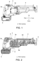
Figure 1 is a side view of awork machine 1 according to an embodiment of the present invention. -
Figure 2 is a side sectional view of thework machine 1. -
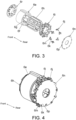
Figure 3 is an exploded perspective view of a stator assembly of amotor 6 of thework machine 1. -
Figure 4 is a perspective view of the stator assembly of themotor 6. -
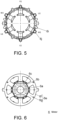
Figure 5 is a rear view of the stator assembly of themotor 6 withstator coils 6h and acircuit board 6n omitted. -
Figure 6 is a sectional view of themotor 6. -
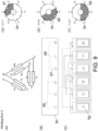
Figure 7 is an explanatory diagram of awinding form 1 in themotor 6. -
Figure 8 is an explanatory diagram of awinding form 2 in themotor 6. -
Figure 9 is an explanatory diagram of awinding form 3 in themotor 6. -
Figure 10 is an explanatory diagram of awinding form 4 in themotor 6. -
Figure 11 is an explanatory diagram of awinding form 5 in themotor 6. -
Figure 12 is a circuit block diagram of thework machine 1. - Hereinafter, the same or equivalent constituent elements, members, etc. shown in each drawing are denoted by the same reference numerals, and duplication of description will be omitted as appropriate. The embodiments are examples rather than limitations of the invention. All features and combinations thereof described in the embodiments are not necessarily essential to the invention.
- The present embodiment relates to a
work machine 1. Thework machine 1 is a saber saw.Figure 1 defines front, rear, and up-down directions of thework machine 1 that are orthogonal to each other. As shown inFigures 1 and 2 , thework machine 1 includes ahousing 3 and afront cover 4 made of, for example, a resin molding. Thefront cover 4 is connected and fixed to a front end portion of thehousing 3. - The
housing 3 has amotor accommodation portion 3a that accommodates amotor 6, and ahandle portion 3b that may be gripped by an operator. Acontrol board 7 is provided below themotor 6 in themotor accommodation portion 3a. Atrigger switch 8 is provided on an upper portion of thehandle portion 3b to be operated by an operator to instruct themotor 6 to be driven or stopped. A battery pack 9 is detachably connected to a lower end portion of thehandle portion 3b. Thework machine 1 operates with power supplied from the battery pack 9. - The
motor 6 is a brushless motor, and is held in themotor accommodation portion 3a of thehousing 3 such that its rotating shaft is parallel to the front-rear direction. The power of themotor 6 is transmitted by atransmission mechanism 50 to asaw blade 5 as an output portion (tip tool). Thetransmission mechanism 50 has a reciprocating drive mechanism that converts the rotation of themotor 6 into a reciprocating motion in the front-rear direction and transmits it to thesaw blade 5, and a swinging mechanism that swings thesaw blade 5 in the up-down direction by the rotation of themotor 6. An operator may switch between enabling and disabling the orbital mode, in which the swing mechanism is operated to swingsaw blade 5 in the up-down direction to cut (truncate) the material, using a change lever (not shown). Here, at least one of thesaw blade 5 and the transmission mechanism corresponds to the output portion. - As shown in
Figures 3 to 6 , themotor 6 includes acylindrical rotor core 6b that is provided around anoutput shaft 6a and rotates together with theoutput shaft 6a; four rotor magnets (permanent magnets) 6c inserted and held in therotor core 6b at intervals of 90 degrees in the circumferential direction; astator core 6e provided to surround outer periphery of therotor core 6b; and sixstator coils 6h (Figures 3 and 4 ) provided in thestator core 6e. Therotor core 6b and therotor magnet 6c constitute the rotor of themotor 6. Thestator core 6e constitutes the stator of themotor 6. The sixstator coils 6h constitute the windings of themotor 6. InFigures 5 and 6 , the illustration of thestator coils 6h is omitted. - The
stator core 6e includes a cylindrical (annular)yoke portion 6f, and sixteeth 6g protruding radially inward from theyoke portion 6f. Each of theteeth 6g is provided with thestator coil 6h. That is, each of theteeth 6g forms a winding slot. As shown in (A) ofFigure 7 and the like, thestator coil 6h has U-phase stator coils U1, U2; V-phase stator coils V1, V2; and W-phase stator coils W1, W2. Thestator coil 6h is arranged in the order of the V-phase stator coil V1, the U-phase stator coil U2, the W-phase stator coil W1, the V-phase stator coil V2, the U-phase stator coil U1, and the W-phase stator coil W2 in the direction around the axis of themotor 6. - As shown in
Figures 3 and 4 , aninsulator 6i is provided on the rear end surface of thestator core 6e. Theinsulator 6i is, for example, a resin molding. Theinsulator 6i holds sixfusing terminals 6j in the circumferential direction at equal angular intervals. Each of thefusing terminals 6j has a rearwardly extending protrudingportion 6k and a hookingportion 6m for hooking an end portion of eachstator coil 6h. Each of thefusing terminals 6j is electrically connected to an end portion of eachstator coil 6h. Acircuit board 6n is connected behind theinsulator 6i. Thecircuit board 6n is fixed to theinsulator 6i by screws or the like so as to be perpendicular to the front-rear direction. Thecircuit board 6n has six throughholes 6p at equal angular intervals in the circumferential direction. The protrudingportion 6k of each of thefusing terminals 6j passes through each of the throughholes 6p and is electrically connected to thecircuit board 6n by soldering or the like. Aninsulator 6r is provided on a front end surface of thestator core 6e. - The winding form of the
motor 6 will be described with reference toFigures 7 to 11 . InFigures 7 to 11 , points u1 and u2 are winding start side end portions of the U-phase stator coils U1 and U2, respectively. Points v1 and v2 are winding start side end portions of the V-phase stator coils V1 and V2, respectively. Points w1 and w2 are winding start side end portions of the W-phase stator coils W1 and W2, respectively. In themotor 6, thestator coil 6h is a delta connection parallel winding. That is, the U-phase stator coils U1 and U2, the V-phase stator coils V1 and V2, and the W-phase stator coils W1 and W2 are delta-connected, and the U-phase stator coils U1 and U2 are connected in parallel, the V-phase stator coils V1 and V2 are connected in parallel, and the W-phase stator coils W1 and W2 are connected in parallel. In the present embodiment, five winding forms of delta connection parallel winding are shown. - (Winding Form 1) (A)-(F) of
Figure 7 relate to a windingform 1. (A) ofFigure 7 is a schematic diagram showing the wiring order of the stator coils (U1, U2, V1, V2, W1, W2) in the windingform 1. (B) ofFigure 7 is a schematic diagram showing the connection relationship of the end portions (u1, u2, v1, v2, w1, w2) of the stator coils on thecircuit board 6n in the windingform 1.Figure 7 (C) is a schematic diagram showing the stator coils and their interconnection relationship when thestator core 6e is unfolded and viewed in the windingform 1. (D)-(F) ofFigure 7 are schematic diagrams showing the conductor patterns of thecircuit board 6n in the windingform 1 by hatching. - As shown in (A) of
Figure 7 and (C) ofFigure 7 , in the windingform 1, windings are sequentially wound aroundteeth 6g that are adjacent in the sixteeth 6g, and are wound in order around the U-phase stator coils U1, the V-phase stator coil V2, the W-phase stator coil W1, the U-phase stator coil U2, the V-phase stator coil V1, and the W-phase stator coil W2. As shown in (B) ofFigure 7 and (D) ofFigure 7 to (F) ofFigure 7 , thecircuit board 6n is formed with afirst conductor pattern 61, asecond conductor pattern 62, and athird conductor pattern 63, each of which is made of, for example, copper foil that functions as a short-circuit portion. - The
first conductor pattern 61 electrically connects one ends (u1, u2) of the U-phase stator coils U1, U2 wound aroundteeth 6g that face each other with the central axis of themotor 6 interposed therebetween. Thesecond conductor pattern 62 electrically connects one ends (v1, v2) of the V-phase stator coils V1 and V2 wound aroundteeth 6g that face each other with the central axis of the motor 6 (hereinafter also referred to as the "central axis") interposed therebetween. Thethird conductor pattern 63 electrically connects one ends (w1, w2) of the W-phasestator coils W 1, W2 wound aroundteeth 6g that face each other with the central axis of themotor 6 interposed therebetween. - In the
circuit board 6n, a first region where thefirst conductor pattern 61 is formed, a second region where thesecond conductor pattern 62 is formed, and a third region where thethird conductor pattern 63 is formed partially overlap each other when viewed from the direction perpendicular to thecircuit board 6n. Thus, thefirst conductor pattern 61, thesecond conductor pattern 62, and thethird conductor pattern 63 are provided in different layers of thecircuit board 6n. Thecircuit board 6n has at least three layers on which conductor patterns may be formed. - (Winding Form 2) (A)-(F) of
Figure 8 relate to a windingform 2. (A) ofFigure 8 is a schematic diagram showing the wiring order of the stator coils (U1, U2, V1, V2, W1, W2) in the windingform 2. (B) ofFigure 8 is a schematic diagram showing the connection relationship of the end portions (u1, u2, v1, v2, w1, w2) of the stator coils on thecircuit board 6n in the windingform 2.Figure 8 (C) is a schematic diagram showing the stator coils and their interconnection relationship when thestator core 6e is unfolded and viewed in the windingform 2. (D)-(F) ofFigure 8 are schematic diagrams showing the conductor patterns of thecircuit board 6n in the windingform 2 by hatching. - As shown in (A) of
Figure 8 and (C) ofFigure 8 , in the windingform 2, windings are sequentially wound aroundteeth 6g that are adjacent in one direction in the sixteeth 6g, then wound aroundteeth 6g that face each other with the central axis interposed therebetween, and wound around teeth that are adjacent in the other direction, thereby winding the U-phase stator coils U1, the V-phase stator coils V2, the W-phase stator coils W1, the W-phase stator coils W2, the V-phase stator coils V1, and the U-phase stator coils U2 in order. As shown in (B) ofFigure 8 and (D) ofFigure 8 to (F) ofFigure 8 , thecircuit board 6n is formed with afirst conductor pattern 64, asecond conductor pattern 65, and athird conductor pattern 66, each of which is made of, for example, copper foil that functions as a short-circuit portion. - The
first conductor pattern 64 is an example of a first short-circuit portion, and electrically connects one ends (u1, w2) of the U-phase stator coil U1 and the W-phase stator coil W2 wound aroundteeth 6g that are adjacent. Thesecond conductor pattern 65 is an example of a second short-circuit portion, and electrically connects one ends (v1, w1) of the V-phase stator coil V1 and the W-phase stator coil W1 wound aroundteeth 6g that are non-adjacent. Thethird conductor pattern 66 is an example of a second short-circuit portion, and electrically connects one ends (u2, w2) of the U-phase stator coil U2 and the W-phase stator coil W2 wound aroundteeth 6g that are non-adjacent. - In the
circuit board 6n, the second region where thesecond conductor pattern 65 is formed and the third region where thethird conductor pattern 66 is formed partially overlap each other when viewed from the direction perpendicular to thecircuit board 6n. On the other hand, the first region where thefirst conductor pattern 64 is formed does not overlap the second region and the third region when viewed from the same direction. For this reason, in (D)-(F) ofFigures 8 , although thefirst conductor pattern 64, thesecond conductor pattern 65, and thethird conductor pattern 66 are provided in different layers of thecircuit board 6n, thesecond conductor pattern 65 and thethird conductor pattern 66 may be provided in different layers of thecircuit board 6n, and thefirst conductor pattern 64 may be provided in the same layer as thesecond conductor pattern 65 or thethird conductor pattern 66. Thecircuit board 6n in this case only needs to have at least two layers on which conductor patterns may be formed. - (Winding Form 3) (A)-(F) of
Figure 9 relate to a windingform 3. (A) ofFigure 9 is a schematic diagram showing the wiring order of the stator coils (U1, U2, V1, V2, W1, W2) in the windingform 3. (B) ofFigure 9 is a schematic diagram showing the connection relationship of the end portions (u1, u2, v1, v2, w1, w2) of the stator coils on thecircuit board 6n in the windingform 3.Figure 9 (C) is a schematic diagram showing the stator coils and their interconnection relationship when thestator core 6e is unfolded and viewed in the windingform 3. (D)-(F) ofFigure 9 are schematic diagrams showing the conductor patterns of thecircuit board 6n in the windingform 3 by hatching. - As shown in (A) of
Figure 9 and (C) ofFigure 9 , in the windingform 3, the windings are wound aroundteeth 6g that face each other, sequentially wound aroundteeth 6g that are adjacent in one direction, wound aroundteeth 6g that face each other, and wound aroundteeth 6g that are adjacent in the other direction, thereby winding the U-phase stator coil U1, the U-phase stator coil U2, the W-phase stator coil W1, the V-phase stator coil V2, the V-phase stator coil V1 and the W-phase stator coil W2 in order. As shown in (B) ofFigure 9 and (D)-(F) ofFigure 9 , thecircuit board 6n is formed with afirst conductor pattern 67, asecond conductor pattern 68, and athird conductor pattern 69, each of which is made of, for example, copper foil that functions as a short-circuit portion. - The
first conductor pattern 67 is an example of a first short-circuit portion, and electrically connects one ends (u2, v1) of the U-phase stator coil U2 and the V-phase stator coil V1 wound aroundteeth 6g that are adjacent. Thesecond conductor pattern 68 is an example of a second short-circuit portion, and electrically connects one ends (v2, w2) of the V-phase stator coil V2 and the W-phase stator coil W2 wound aroundteeth 6 that are non-adjacent. Thethird conductor pattern 69 is an example of a second short-circuit portion, and electrically connects one ends (u1, w1) of the U-phase stator coil U1 and the W-phase stator coil W1 wound aroundteeth 6 that are non-adjacent. - In the
circuit board 6n, the second region where thesecond conductor pattern 68 is formed and the third region where thethird conductor pattern 69 is formed partially overlap each other when viewed from the direction perpendicular to thecircuit board 6n. On the other hand, the first region where thefirst conductor pattern 67 is formed does not overlap the second region and the third region when viewed from the same direction. For this reason, although thefirst conductor pattern 67, thesecond conductor pattern 68, and thethird conductor pattern 69 are provided in different layers of thecircuit board 6n in (D)-(F) ofFigure 9 , thesecond conductor pattern 68 and thethird conductor pattern 69 may be provided in different layers of thecircuit board 6n, and thefirst conductor pattern 67 may be provided in the same layer as thesecond conductor pattern 68 or thethird conductor pattern 69. Thecircuit board 6n in this case only needs to have at least two layers on which conductor patterns may be formed. - (Winding Form 4) (A)-(F) of
Figure 10 relate to a windingform 4. (A) ofFigure 10 is a schematic diagram showing the wiring order of the stator coils (U1, U2, V1, V2, W1, W2) in the windingform 4. (B) ofFigure 10 is a schematic diagram showing the connection relationship of the end portions (u1, u2, v1, v2, w1, w2) of the stator coils on thecircuit board 6n in the windingform 4.Figure 10 (C) is a schematic diagram showing the stator coils and their interconnection relationship when thestator core 6e is unfolded and viewed in the windingform 4. Figure (D)-(F) ofFigure 10 are schematic diagrams showing the conductor patterns of thecircuit board 6n in the windingform 4 by hatching. - (A) of
Figure 10 and (C) ofFigure 10 , in the windingform 4, the windings are wound around everyother teeth 6g in one direction in the sixteeth 6g, wound aroundteeth 6g that face each other, and wound around everyother teeth 6g in the other direction, thereby winding the U-phase stator coil U1, the V-phase stator coil V1, the W-phase stator coil W1, the W-phase stator coil W2, the V-phase stator coil V2, and the U-phase stator coil U2 in order. As shown in (B) ofFigure 10 and (D)-(F) ofFigure 10 , thecircuit board 6n is formed with afirst conductor pattern 70, asecond conductor pattern 71, and athird conductor pattern 72, each of which is made of, for example, copper foil that functions as a short-circuit portion. - The
first conductor pattern 70 electrically connects one ends (u1, w2) of the U-phase stator coil U1 and the W-phase stator coil W2 wound aroundteeth 6g that are adjacent. Thesecond conductor pattern 71 electrically connects one ends (u2, v1) of the U-phase stator coil U2 and the V-phase stator coil V1 wound aroundteeth 6g that are adjacent. Thethird conductor pattern 72 electrically connects one ends (v2, w1) of the V-phase stator coil V2 and the W-phase stator coil W1 wound aroundteeth 6g that are adjacent. - In the
circuit board 6n, the first region where thefirst conductor pattern 70 is formed, the second region where thesecond conductor pattern 71 is formed, and the third region where thethird conductor pattern 72 is formed are not overlapped when viewed from the direction perpendicular to thecircuit board 6n. For this reason, in (D)-(F) ofFigure 10 , thefirst conductor pattern 70, thesecond conductor pattern 71, and thethird conductor pattern 72 are provided in different layers of thecircuit board 6n, but thefirst conductor pattern 70, thesecond conductor pattern 71, and thethird conductor pattern 72 may be provided in the same layer of thecircuit board 6n. Moreover, two of thefirst conductor pattern 70, thesecond conductor pattern 71, and thethird conductor pattern 72 may be provided in the same layer, and the remaining one may be provided in another layer. That is, thecircuit board 6n only needs to have at least one layer on which a conductor pattern may be formed. - (Winding Form 5) (A)-(F) of
Figure 11 relate to a windingform 5. (A) ofFigure 11 is a schematic diagram showing the wiring order of the stator coils (U1, U2, V1, V2, W1, W2) in the windingform 5. (B) ofFigure 11 is a schematic diagram showing the connection relationship of the end portions (u1, u2, v1, v2, w1, w2) of the stator coils on thecircuit board 6n in the windingform 5.Figure 11 (C) is a schematic diagram showing the stator coils and their interconnection relationship when thestator core 6e is unfolded and viewed in the windingform 5. As shown in (D)-(F) ofFigure 11 are schematic diagrams showing the conductor patterns of thecircuit board 6n in the windingform 5 by hatching. - As shown in (A) of
Figure 11 and (C) ofFigure 11 , in the windingform 5, the windings are wound aroundteeth 6g that face each other in the sixteeth 6g, wound around everyother teeth 6g in one direction, wound aroundteeth 6g that face each other, and wound around everyother teeth 6g in the other direction, thereby winding the U-phase stator coil U1, the U-phase stator coil U2, the W-phase stator coil W2, the V-phase stator coil V2, the V-phase stator coil V1, and the W-phase stator coil W1 in order. As shown in (B) ofFigure 11 and (D)-(F) ofFigure 11 , thecircuit board 6n is formed with afirst conductor pattern 73, asecond conductor pattern 74, and athird conductor pattern 75, each of which is made of, for example, copper foil that functions as a short-circuit portion. - The
first conductor pattern 73 electrically connects one ends (u1, w2) of the U-phase stator coil U1 and the W-phase stator coil W2 wound aroundteeth 6g that are adjacent. Thesecond conductor pattern 74 electrically connects one ends (u2, v1) of the U-phase stator coil U2 and the V-phase stator coil V1 wound aroundteeth 6g that are adjacent. Thethird conductor pattern 75 electrically connects one ends (v2, w1) of the V-phase stator coil V2 and the W-phase stator coil W1 wound aroundteeth 6g that are adjacent. - In the
circuit board 6n, the first region where thefirst conductor pattern 73 is formed, the second region where thesecond conductor pattern 74 is formed, and the third region where thethird conductor pattern 75 is formed are not overlapped when viewed from the direction perpendicular to thecircuit board 6n. For this reason, in (D)-(F) ofFigure 11 , although thefirst conductor pattern 73, thesecond conductor pattern 74, and thethird conductor pattern 75 are provided in different layers of thecircuit board 6n, thefirst conductor pattern 73, thesecond conductor pattern 74, and thethird conductor pattern 75 may be provided in the same layer of thecircuit board 6n. Moreover, two of thefirst conductor pattern 73, thesecond conductor pattern 74, and thethird conductor pattern 75 may be provided in the same layer, and the remaining one may be provided in another layer. That is, thecircuit board 6n only needs to have at least one layer on which a conductor pattern may be formed. Further, in any winding form, thecircuit board 6n may be further provided with a layer for arranging a rotation detection element (amagnetic sensor 43 to be described later) for detecting rotation of themotor 6, or a layer on which a conductor pattern is formed may be used. The rotation detection element is preferably provided in a layer facing the motor 6 (rotor). -
Figure 12 is a circuit block diagram of thework machine 1. Aninverter circuit 42 is composed of switching elements Q1 to Q6 such as FETs and IGBTs connected in a three-phase bridge. Themagnetic sensor 43 such as a Hall IC is arranged near themotor 6 and outputs a signal corresponding to the rotational position of themotor 6. Thecontrol board 7 is provided with acontrol unit 41, acurrent detection circuit 44, a controlpower supply circuit 45, a drivesignal output circuit 47, and a rotationalposition detection circuit 48. - The
current detection circuit 44 detects the current of themotor 6 from the voltage at both ends of the resistor Rs provided in the current path of themotor 6 and transmits it to thecontrol unit 41. The controlpower supply circuit 45 converts the voltage of the battery pack 9 into power supply voltage for thecontrol unit 41 and the like, and supplies it to thecontrol unit 41 and the like. The drivesignal output circuit 47 outputs drive signals to switching elements Q1 to Q6 of theinverter circuit 42 under the control of thecontrol unit 41. The rotationalposition detection circuit 48 detects the rotational position of themotor 6 from the output signal of themagnetic sensor 43 and transmits it to thecontrol unit 41. Thecontrol unit 41 includes a microcontroller and the like, and controls theinverter circuit 42 through the drivesignal output circuit 47 in the mode set by amode setting switch 46 according to the operation of thetrigger switch 8, so as to control the driving of themotor 6. - According to this embodiment, the following effects can be obtained.
- (1) Since short-circuiting (connection) between the
stator coils 6h required for delta connection parallel winding is performed by the conductor pattern provided on thecircuit board 6n, the connection between thestator coils 6h can be easily performed. Thus, it is possible to suppress the complication of the configuration while adopting the delta connection parallel winding which is advantageous for increasing the output, and easily assembly the motor 6 (improved assemblability). Moreover, the degree of freedom in design can be improved. Moreover, since thecircuit board 6n may be used as a sensor board for detecting the rotation of themotor 6, there is no need to provide a member dedicated to short-circuiting. - (2) According to the winding
form 1, since the sixteeth 6g are sequentially wound aroundteeth 6g that are adjacent, the connecting wire for passing between the stator coils around the central axis is simple and may be easily connected. - (3) According to the winding
forms form 1, the conductor patterns for short circuiting may be made smaller, and the number of layers of thecircuit board 6n can be further reduced. Thus, a substrate with two layers can be realized. - (4) According to the winding
forms forms circuit board 6n can be reduced by up to two layers. Thus, a substrate of one layer can be realized. - Although the invention has been described above using the example of the embodiments, it is understood by those skilled in the art that various modifications may be made to each component and each processing process of the embodiments within the scope of the claims. Modifications will be discussed below.
- The
work machine 1 is not limited to a saver saw, and may be of other types having a brushless motor. Thework machine 1 is not limited to a cordless type that operates on power from the battery pack 9, and may be a corded type that operates on power supplied from an external AC power supply. The number of theteeth 6g and thestator coils 6h, and the number of the rotor magnets, and the like are not limited to the specific numbers exemplified in the embodiments and are arbitrary. -
- 1
- work machine
- 3
- housing
- 3a
- motor accommodation portion
- 3b
- handle portion
- 4
- front cover
- 5
- saw blade (tip tool)
- 6
- motor (electric motor)
- 6a
- output shaft (rotating shaft)
- 6b
- rotor core
- 6c
- rotor magnet
- 6e
- stator core
- 6h
- stator coil
- 6f
- yoke portion
- 6g
- teeth (salient pole)
- 6h
- stator coil
- 6i
- insulator
- 6j
- fusing terminal
- 6k
- protruding portion
- 6m
- hooking portion
- 6n
- circuit board
- 6p
- through hole
- 6r
- insulator
- 7
- control board
- 8
- trigger switch
- 9
- battery pack
- 61-75
- conductor pattern
Claims (13)
- A work machine, comprising:a brushless motor having a stator having a plurality of teeth, a rotor rotating with respect to the stator, and a winding having coils wound around each of the plurality of teeth; andan output portion driven by the brushless motor, the work machine further comprising:
a short-circuit portion having a first short-circuit portion that connects coils wound around teeth that are adjacent and a second short-circuit portion that connects coils wound around teeth that are non-adjacent. - A work machine, comprising:a brushless motor having a stator having a plurality of teeth, a rotor rotating with respect to the stator, and a winding wound around the stator;a circuit board to which the winding is connected; andan output portion driven by the brushless motor,wherein the winding has a plurality of coils forming mutually different phases and a plurality of coils forming the same phase, andthe plurality of coils forming mutually different phases and/or the plurality of coils forming the same phase are connected by a short-circuit portion provided on the circuit board.
- The work machine according to claim 1 or 2, comprising:a circuit board to which the winding is connected,wherein the short-circuit portion is a pattern formed on the circuit board.
- The work machine according to any one of claims 1 to 3, comprising:
wherein in the winding, a plurality of the coils of different phases are delta-connected, and a plurality of the coils of the same phase are connected in parallel. - The work machine according to claim 4,
wherein the winding is sequentially wound around teeth that are adjacent in the plurality of teeth. - The work machine according to claim 3,wherein a first pattern for connecting coils wound around the teeth that are non-adjacent or that face each other is formed in a first region of the circuit board;a second pattern for connecting coils wound around the teeth that are non-adjacent or that face each other is formed in a second region of the circuit board; anda third pattern for connecting coils wound around the teeth that are non-adjacent or that face each other is formed in a third region of the circuit board.
- The work machine according to claim 4,
wherein the winding is sequentially wound around teeth that are adjacent in one direction in the plurality of teeth, then wound around teeth that face each other in the plurality of teeth, and wound around teeth that are adjacent in the other direction. - The work machine according to claim 4,
wherein the winding is wound around teeth that face each other, sequentially wound around teeth that are adjacent in one direction, wound around teeth that face each other, and wound around teeth that are adjacent in the other direction. - The work machine according to claim 3,wherein a first pattern for connecting coils wound around the teeth that are adjacent is formed in a first region of the circuit board;a second pattern for connecting coils wound around the teeth that are non-adjacent is formed in a second region of the circuit board; anda third pattern for connecting coils wound around the teeth that are non-adjacent is formed in a third region of the circuit board.
- The work machine according to claim 4,
wherein the winding is wound around every other teeth in one direction in the plurality of teeth, wound around teeth that face each other, and wound around every other teeth in the other direction. - The work machine according to claim 4,wherein the stator has a plurality of teeth around which the winding is wound, andthe winding is wound around teeth that face each other in the plurality of teeth, wound around every other teeth in one direction, wound around teeth that face each other, and wound around every other teeth in the other direction.
- The work machine according to claim 3,wherein a first pattern for connecting coils wound around the teeth that are adjacent is formed in a first region of the circuit board;a second pattern for connecting coils wound around another of the teeth that are adjacent is formed in a second region of the circuit board; anda third pattern for connecting coils wound around yet another of the teeth that are adjacent is formed in a third region of the circuit board.
- A work machine, comprising:a brushless motor having a stator having a plurality of teeth, a rotor rotating with respect to the stator, and a winding wound around the stator;a circuit board to which the winding is connected; andan output portion driven by the brushless motor,wherein the winding has a plurality of delta-connected coils forming mutually different phases and a plurality of parallel-connected coils forming the same phase, andthe plurality of delta-connected coils and the plurality of parallel-connected coils are connected by a pattern formed on the circuit board.
Applications Claiming Priority (2)
| Application Number | Priority Date | Filing Date | Title |
|---|---|---|---|
| JP2020181851 | 2020-10-29 | ||
| PCT/JP2021/039073 WO2022091964A1 (en) | 2020-10-29 | 2021-10-22 | Work machine |
Publications (2)
| Publication Number | Publication Date |
|---|---|
| EP4239863A1 true EP4239863A1 (en) | 2023-09-06 |
| EP4239863A4 EP4239863A4 (en) | 2024-04-24 |
Family
ID=81383868
Family Applications (1)
| Application Number | Title | Priority Date | Filing Date |
|---|---|---|---|
| EP21886082.3A Pending EP4239863A4 (en) | 2020-10-29 | 2021-10-22 | WORKING MACHINE |
Country Status (5)
| Country | Link |
|---|---|
| US (1) | US20230402899A1 (en) |
| EP (1) | EP4239863A4 (en) |
| JP (1) | JP7537510B2 (en) |
| CN (1) | CN116438730A (en) |
| WO (1) | WO2022091964A1 (en) |
Families Citing this family (2)
| Publication number | Priority date | Publication date | Assignee | Title |
|---|---|---|---|---|
| EP4205910B1 (en) * | 2021-12-28 | 2025-01-29 | Nanjing Chervon Industry Co., Ltd. | Power tool |
| JP7371714B2 (en) * | 2022-03-08 | 2023-10-31 | 株式会社富士通ゼネラル | 3-phase motor manufacturing method and 3-phase motor |
Family Cites Families (11)
| Publication number | Priority date | Publication date | Assignee | Title |
|---|---|---|---|---|
| FR1300368A (en) * | 1960-07-05 | 1962-08-03 | Nat Res Dev | Improvements to rotating electrical machines |
| EP0768750B1 (en) * | 1995-03-30 | 2002-06-12 | Nikkiso Co., Ltd. | Switched-reluctance rotary machine |
| DE202005016915U1 (en) * | 2004-11-10 | 2006-01-05 | Ebm-Papst St. Georgen Gmbh & Co. Kg | Electric motor for mining industry, has fixing units connected with end of coil, and conductive strips connected with connecting units of stators by welded joint to interconnect connecting units electrically with one another |
| JPWO2009139067A1 (en) * | 2008-05-16 | 2011-09-15 | 三菱電機株式会社 | Rotating electric machine |
| US9450472B2 (en) * | 2010-06-14 | 2016-09-20 | Black & Decker, Inc. | Rotor assembly for brushless motor for a power tool |
| JP5928642B2 (en) * | 2014-07-01 | 2016-06-01 | ダイキン工業株式会社 | Armature, rotating electric machine, cross flow fan, armature tooth pair manufacturing method |
| JP6507773B2 (en) | 2015-03-25 | 2019-05-08 | 工機ホールディングス株式会社 | Hand-held power tool |
| DE102015110127A1 (en) * | 2015-06-24 | 2016-12-29 | Alber Gmbh | DC machine |
| US10511201B2 (en) * | 2016-03-25 | 2019-12-17 | Amotech Co., Ltd. | Stacking-type stator using multilayer printed circuit board, and single-phase motor and cooling fan using same |
| DE102017128479A1 (en) * | 2017-11-30 | 2019-06-06 | Feaam Gmbh | Electric machine, control unit and method for operating an electric machine |
| WO2019151395A1 (en) * | 2018-01-31 | 2019-08-08 | 工機ホールディングス株式会社 | Brushless motor and electric apparatus using same |
-
2021
- 2021-10-22 CN CN202180073864.4A patent/CN116438730A/en active Pending
- 2021-10-22 EP EP21886082.3A patent/EP4239863A4/en active Pending
- 2021-10-22 WO PCT/JP2021/039073 patent/WO2022091964A1/en not_active Ceased
- 2021-10-22 US US18/033,790 patent/US20230402899A1/en active Pending
- 2021-10-22 JP JP2022559087A patent/JP7537510B2/en active Active
Also Published As
| Publication number | Publication date |
|---|---|
| US20230402899A1 (en) | 2023-12-14 |
| JPWO2022091964A1 (en) | 2022-05-05 |
| WO2022091964A1 (en) | 2022-05-05 |
| JP7537510B2 (en) | 2024-08-21 |
| EP4239863A4 (en) | 2024-04-24 |
| CN116438730A (en) | 2023-07-14 |
Similar Documents
| Publication | Publication Date | Title |
|---|---|---|
| US11837934B2 (en) | Stator assembly for a brushless motor in a power tool | |
| JP5656436B2 (en) | Stator coils, rotating electrical machines and automobiles | |
| CN104875166B (en) | Electric tool | |
| CN107591922B (en) | Electric tool | |
| JP7684467B2 (en) | electric work equipment | |
| JP4688910B2 (en) | Electric power steering motor | |
| CN113853730A (en) | Drive device and electric power steering device | |
| JP2017121158A (en) | Motor and power tool | |
| CN108886313B (en) | electric motor | |
| JP7537510B2 (en) | Work Machine | |
| CN110810017A (en) | Electric working machine | |
| CN107681801A (en) | Electric tool | |
| JP2019047605A (en) | Electrical device | |
| JP2008503996A (en) | Automotive motor drive | |
| WO2019151395A1 (en) | Brushless motor and electric apparatus using same | |
| CN107662189B (en) | electrical tools | |
| KR20190007907A (en) | Motor | |
| JP2019115176A (en) | Rotary electric machine | |
| WO2024247891A1 (en) | Work machine | |
| US20250105682A1 (en) | Brushless motor for a power tool | |
| KR101383257B1 (en) | Stator Having 3-Core Connection Structure and BLDC Motor Using the Same | |
| WO2023276354A1 (en) | Work machine | |
| WO2024203180A1 (en) | Work machine | |
| JP2023005982A (en) | work machine | |
| WO2026044105A1 (en) | Power tools including axial flux motors |
Legal Events
| Date | Code | Title | Description |
|---|---|---|---|
| STAA | Information on the status of an ep patent application or granted ep patent |
Free format text: STATUS: THE INTERNATIONAL PUBLICATION HAS BEEN MADE |
|
| PUAI | Public reference made under article 153(3) epc to a published international application that has entered the european phase |
Free format text: ORIGINAL CODE: 0009012 |
|
| STAA | Information on the status of an ep patent application or granted ep patent |
Free format text: STATUS: REQUEST FOR EXAMINATION WAS MADE |
|
| 17P | Request for examination filed |
Effective date: 20230426 |
|
| AK | Designated contracting states |
Kind code of ref document: A1 Designated state(s): AL AT BE BG CH CY CZ DE DK EE ES FI FR GB GR HR HU IE IS IT LI LT LU LV MC MK MT NL NO PL PT RO RS SE SI SK SM TR |
|
| DAV | Request for validation of the european patent (deleted) | ||
| DAX | Request for extension of the european patent (deleted) | ||
| A4 | Supplementary search report drawn up and despatched |
Effective date: 20240321 |
|
| RIC1 | Information provided on ipc code assigned before grant |
Ipc: H02K 7/14 20060101ALN20240315BHEP Ipc: B25F 5/00 20060101ALI20240315BHEP Ipc: H02K 3/28 20060101AFI20240315BHEP |