EP4239786A1 - Frequency adjustable filter - Google Patents
Frequency adjustable filter Download PDFInfo
- Publication number
- EP4239786A1 EP4239786A1 EP23157915.2A EP23157915A EP4239786A1 EP 4239786 A1 EP4239786 A1 EP 4239786A1 EP 23157915 A EP23157915 A EP 23157915A EP 4239786 A1 EP4239786 A1 EP 4239786A1
- Authority
- EP
- European Patent Office
- Prior art keywords
- resonator element
- movable
- hole
- actuator
- bar
- Prior art date
- Legal status (The legal status is an assumption and is not a legal conclusion. Google has not performed a legal analysis and makes no representation as to the accuracy of the status listed.)
- Pending
Links
Images




Classifications
-
- H—ELECTRICITY
- H01—ELECTRIC ELEMENTS
- H01P—WAVEGUIDES; RESONATORS, LINES, OR OTHER DEVICES OF THE WAVEGUIDE TYPE
- H01P1/00—Auxiliary devices
- H01P1/20—Frequency-selective devices, e.g. filters
-
- H—ELECTRICITY
- H01—ELECTRIC ELEMENTS
- H01P—WAVEGUIDES; RESONATORS, LINES, OR OTHER DEVICES OF THE WAVEGUIDE TYPE
- H01P1/00—Auxiliary devices
- H01P1/20—Frequency-selective devices, e.g. filters
- H01P1/207—Hollow waveguide filters
-
- H—ELECTRICITY
- H01—ELECTRIC ELEMENTS
- H01P—WAVEGUIDES; RESONATORS, LINES, OR OTHER DEVICES OF THE WAVEGUIDE TYPE
- H01P1/00—Auxiliary devices
- H01P1/20—Frequency-selective devices, e.g. filters
- H01P1/201—Filters for transverse electromagnetic waves
- H01P1/205—Comb or interdigital filters; Cascaded coaxial cavities
-
- H—ELECTRICITY
- H01—ELECTRIC ELEMENTS
- H01P—WAVEGUIDES; RESONATORS, LINES, OR OTHER DEVICES OF THE WAVEGUIDE TYPE
- H01P1/00—Auxiliary devices
- H01P1/20—Frequency-selective devices, e.g. filters
- H01P1/201—Filters for transverse electromagnetic waves
- H01P1/205—Comb or interdigital filters; Cascaded coaxial cavities
- H01P1/2053—Comb or interdigital filters; Cascaded coaxial cavities the coaxial cavity resonators being disposed parall to each other
-
- H—ELECTRICITY
- H01—ELECTRIC ELEMENTS
- H01P—WAVEGUIDES; RESONATORS, LINES, OR OTHER DEVICES OF THE WAVEGUIDE TYPE
- H01P1/00—Auxiliary devices
- H01P1/20—Frequency-selective devices, e.g. filters
- H01P1/207—Hollow waveguide filters
- H01P1/208—Cascaded cavities; Cascaded resonators inside a hollow waveguide structure
-
- H—ELECTRICITY
- H01—ELECTRIC ELEMENTS
- H01P—WAVEGUIDES; RESONATORS, LINES, OR OTHER DEVICES OF THE WAVEGUIDE TYPE
- H01P7/00—Resonators of the waveguide type
- H01P7/04—Coaxial resonators
-
- H—ELECTRICITY
- H01—ELECTRIC ELEMENTS
- H01P—WAVEGUIDES; RESONATORS, LINES, OR OTHER DEVICES OF THE WAVEGUIDE TYPE
- H01P7/00—Resonators of the waveguide type
- H01P7/06—Cavity resonators
Definitions
- Various example embodiments relate to wireless communications, and especially to frequency adjustable filters.
- Wireless communication systems are under constant development. In the long term, more spectrum will be needed to maintain quality of service and meet growing demand. Frequency adjustable filters facilitate to achieve efficient use of the spectrum in use.
- a frequency adjustable filter comprising at least a housing, which comprises one or more cavities closed by a lid above the housing, the frequency adjustable filter comprising, per a cavity forming a resonator, at least: a first resonator element extending from the lid towards a bottom of the cavity on an opposite side of the lid; a second resonator element extending from the bottom towards the lid, the second resonator element partially overlapping the first resonator element; an adjusting bar extending inside an area in which the first resonator element and the second resonator element are overlapping, the adjusting bar being arranged to move within said area; a first hole either in the lid or in the bottom; a driving shaft; and an actuator arranged to move the adjusting bar through the first hole by means of the driving shaft, wherein at least the first resonator element, the second resonator element and the adjusting bar are positioned to have a common vertical central axis.
- the first resonator element is a first cylinder and the second resonator element is a second cylinder, one of the first and second cylinders extending inside the other one of the first and second cylinders.
- the first cylinder and the second cylinder are metallic cylinders.
- the frequency adjustable filter further comprises, per the cavity forming the resonator, when the first hole is in the lid, a support structure attached to the lid, arranged on the upper surface of the lid above the cavity, wherein the driving shaft is fixedly attached to the support structure; the actuator is a movable actuator arranged to move along the driving shaft; and the adjusting bar is attached to the actuator to move as the actuator move.
- the movable actuator comprises a second hole for the driving shaft; and the adjusting bar is attached to the bottom part of the movable actuator and comprises a hollow to accommodate the driving shaft, wherein the first hole, the second hole, and the movable actuator are positioned to have a common vertical central axis with the first resonator element, the second resonator element and the adjusting bar.
- the movable actuator comprises a second hole for the driving shaft; and the adjusting bar is attached to a vertical side of the movable actuator.
- the first resonator element has an upper end cover comprising a third hole through which the adjustable bar extends inside the area in which the first resonator element and the second resonator element are overlapping, the third hole having a common central axis with the first hole.
- the first hole in the lid is dimensioned to accommodate the actuator and the adjusting bar attached to the actuator; and the upper end cover comprises a fourth hole between the first hole in the lid and the third hole, the fourth hole being dimensioned to accommodate the actuator and the adjusting bar attached to the actuator.
- the frequency adjustable filter further comprises mechanical means for adjusting the position of the adjusting bar inside the area in which the first resonator element and the second resonator element are overlapping, the mechanical means being attached to the support structure.
- the adjusting bar comprises a movable bar portion, a movable dielectric portion between the first resonator element and the second resonator element in the area in which the first resonator element and the second resonator element are overlapping, and a support portion between the movable bar portion and the movable dielectric portion, to move the movable dielectric portion according to the movement of the movable bar portion;
- the driving shaft is fixedly attached to the actuator;
- the first hole is dimensioned to accommodate the actuator; and the movable bar is arranged to move along the driving shaft.
- an outer horizontal cross section of the movable bar portion is dimensioned to be substantially equal to an inner horizontal cross section of the second resonator element.
- the movable dielectric portion is a movable dielectric element
- the movable bar portion is a movable bar
- the support portion is a support structure attached to the movable dielectric element and the movable bar or the support portion is part of the movable dielectric element or part of the movable bar.
- the support portion is made of plastic and/or the movable bar portion is made of plastic.
- an apparatus comprising a plurality of frequency adjustable filters; at least one processor; and at least one memory including computer program code, the at least one memory and computer program code configured to, with the at least one processor, cause the apparatus at least to perform: filtering transmission over a radio interface using said plurality of frequency adjustable filters, wherein a frequency adjustable filter comprises at least a housing comprising one or more cavities closed by a lid above the housing, the frequency adjustable filter comprising, per a cavity forming a resonator, at least: a first resonator element extending from the lid towards a bottom of the cavity on an opposite side of the lid; a second resonator element extending from the bottom towards the lid, the second resonator element partially overlapping the first resonator element; an adjusting bar extending inside an area in which the first resonator element and the second resonator element are overlapping, the adjusting bar being arranged to move within said area; a first hole either in the lid or in the bottom; a driving shaft; and
- the movable actuator comprises a second hole for the driving shaft.
- UMTS universal mobile telecommunications system
- UTRAN radio access network
- LTE long term evolution
- WLAN wireless local area network
- WiFi worldwide interoperability for microwave access
- PCS personal communications services
- WCDMA wideband code division multiple access
- UWB ultra-wideband
- IMS Internet Protocol multimedia subsystems
- Figure 1 depicts examples of simplified system architectures only showing some elements and functional entities, all being logical units, whose implementation may differ from what is shown.
- the connections shown in Figure 1 are logical connections; the actual physical connections may be different. It is apparent to a person skilled in the art that the system typically comprises also other functions and structures than those shown in Figure 1 .
- Figure 1 shows a part of an exemplifying radio access network.
- Figure 1 shows user devices 101, 101' configured to be in a wireless connection on one or more communication channels with a node 102.
- the node 102 is further connected to a core network 105.
- the node 102 may be an access node such as (e/g)NodeB providing or serving devices in a cell.
- the node 102 may be a non-3GPP access node.
- the physical link from a device to a (e/g)NodeB is called uplink or reverse link and the physical link from the (e/g)NodeB to the device is called downlink or forward link.
- (e/g)NodeBs or their functionalities may be implemented by using any node, host, server or access point etc. entity suitable for such a usage.
- a communications system typically comprises more than one (e/g)NodeB in which case the (e/g)NodeBs may also be configured to communicate with one another over links, wired or wireless, designed for the purpose. These links may be used for signaling purposes.
- the (e/g)NodeB is a computing device configured to control the radio resources of communication system it is coupled to.
- the NodeB may also be referred to as a base station, an access point or any other type of interfacing device including a relay station capable of operating in a wireless environment.
- the (e/g)NodeB includes or is coupled to transceivers. From the transceivers of the (e/g)NodeB, a connection is provided to an antenna unit that establishes bi-directional radio links to devices.
- the antenna unit may comprise a plurality of antennas or antenna elements.
- the (e/g)NodeB is further connected to the core network 105 (CN or next generation core NGC).
- the counterpart on the CN side can be a serving gateway (S-GW, routing and forwarding user data packets), packet data network gateway (P-GW), for providing connectivity of user devices (UEs) to external packet data networks, or mobile management entity (MME), or access and mobility management function (AMF), etc.
- S-GW serving gateway
- P-GW packet data network gateway
- MME mobile management entity
- AMF access and mobility management function
- the user device also called UE, user equipment, user terminal, terminal device, etc.
- UE user equipment
- user terminal terminal device
- any feature described herein with a user device may be implemented with a corresponding apparatus, such as a relay node.
- a relay node is a layer 3 relay (self-backhauling relay) towards the base station.
- the user device typically refers to a device (e.g. a portable or non-portable computing device) that includes wireless mobile communication devices operating with or without a subscriber identification module (SIM), including, but not limited to, the following types of devices: a mobile station (mobile phone), smartphone, personal digital assistant (PDA), handset, device using a wireless modem (alarm or measurement device, etc.), laptop and/or touch screen computer, tablet, game console, notebook, and multimedia device.
- SIM subscriber identification module
- a mobile station mobile phone
- smartphone personal digital assistant
- PDA personal digital assistant
- handset device using a wireless modem (alarm or measurement device, etc.)
- laptop and/or touch screen computer tablet, game console, notebook, and multimedia device.
- a device may also be a nearly exclusive uplink only device, of which an example is a camera or video camera loading images or video clips to a network.
- a device may also be a device having capability to operate in Internet of Things (IoT) network which is a scenario in which objects are provided with the ability to transfer data over a network without requiring human-to-human or human-to-computer interaction, e.g. to be used in smart power grids and connected vehicles.
- IoT Internet of Things
- the user device may also utilize cloud.
- a user device may comprise a user portable device with radio parts (such as a watch, earphones, eyeglasses, other wearable accessories or wearables) and the computation is carried out in the cloud.
- the device (or in some embodiments a layer 3 relay node) is configured to perform one or more of user equipment functionalities.
- the user device may also be called a subscriber unit, mobile station, remote terminal, access terminal, user terminal or user equipment (UE) just to mention but a few names or apparatuses.
- CPS cyber-physical system
- ICT devices sensors, actuators, processors microcontrollers, etc.
- Mobile cyber physical systems in which the physical system in question has inherent mobility, are a subcategory of cyber-physical systems. Examples of mobile physical systems include mobile robotics and electronics transported by humans or animals.
- apparatuses have been depicted as single entities, different units, processors and/or memory units (not all shown in Figure 1 ) may be implemented.
- 5G enables using multiple input - multiple output (MIMO) antennas, many more base stations or nodes than the LTE (a so-called small cell concept), including macro sites operating in co-operation with smaller stations and employing a variety of radio technologies depending on service needs, use cases and/or spectrum available.
- MIMO multiple input - multiple output
- 5G mobile communications supports a wide range of use cases and related applications including video streaming, augmented reality, different ways of data sharing and various forms of machine type applications (such as (massive) machine-type communications (mMTC), including vehicular safety, different sensors and real-time control.
- 5G is expected to have multiple radio interfaces, namely below 6GHz, cmWave and mmWave, and also being integrable with existing legacy radio access technologies, such as the LTE.
- Integration with the LTE may be implemented, at least in the early phase, as a system, where macro coverage is provided by the LTE and 5G radio interface access comes from small cells by aggregation to the LTE.
- 5G is planned to support both inter-RAT operability (such as LTE-5G) and inter-RI operability (inter-radio interface operability, such as below 6GHz - cmWave, below 6GHz - cmWave - mmWave).
- inter-RAT operability such as LTE-5G
- inter-RI operability inter-radio interface operability, such as below 6GHz - cmWave, below 6GHz - cmWave - mmWave.
- One of the concepts considered to be used in 5G networks is network slicing in which multiple independent and dedicated virtual sub-networks (network instances) may be created within the same infrastructure to run services that have different requirements on latency, reliability, throughput and mobility.
- the current architecture in LTE networks is fully distributed in the radio and fully centralized in the core network.
- the low latency applications and services in 5G require to bring the content close to the radio which leads to local break out and multi-access edge computing (MEC).
- MEC multi-access edge computing
- 5G enables analytics and knowledge generation to occur at the source of the data. This approach requires leveraging resources that may not be continuously connected to a network such as laptops, smartphones, tablets and sensors.
- MEC provides a distributed computing environment for application and service hosting. It also has the ability to store and process content in close proximity to cellular subscribers for faster response time.
- Edge computing covers a wide range of technologies such as wireless sensor networks, mobile data acquisition, mobile signature analysis, cooperative distributed peer-to-peer ad hoc networking and processing also classifiable as local cloud/fog computing and grid/mesh computing, dew computing, mobile edge computing, cloud-let, distributed data storage and retrieval, autonomic self-healing networks, remote cloud services, augmented and virtual reality, data caching, Internet of Things (massive connectivity and/or latency critical), critical communications (autonomous vehicles, traffic safety, real-time analytics, time-critical control, healthcare applications).
- technologies such as wireless sensor networks, mobile data acquisition, mobile signature analysis, cooperative distributed peer-to-peer ad hoc networking and processing also classifiable as local cloud/fog computing and grid/mesh computing, dew computing, mobile edge computing, cloud-let, distributed data storage and retrieval, autonomic self-healing networks, remote cloud services, augmented and virtual reality, data caching, Internet of Things (massive connectivity and/or latency critical), critical communications
- the communication system is also able to communicate with other networks, such as a public switched telephone network or the Internet 106, or utilize services provided by them.
- the communication network may also be able to support the usage of cloud services, for example at least part of core network operations may be carried out as a cloud service (this is depicted in Figure 1 by "cloud" 107).
- the communication system may also comprise a central control entity, or a like, providing facilities for networks of different operators to cooperate for example in spectrum sharing.
- Edge cloud may be brought into a radio access network (RAN) by utilizing network function virtualization (NVF) and software defined networking (SDN).
- RAN radio access network
- NVF network function virtualization
- SDN software defined networking
- Using the technology of edge cloud may mean access node operations to be carried out, at least partly, in a server, host or node operationally coupled to a remote radio head or base station comprising radio parts. It is also possible that node operations will be distributed among a plurality of servers, nodes or hosts.
- Application of cloudRAN architecture enables RAN real time functions being carried out at the RAN side (in a distributed unit, DU 102) and non-real time functions being carried out in a centralized manner (in a centralized unit, CU 104).
- 5G may also utilize satellite communication to enhance or complement the coverage of 5G service, for example by providing backhauling.
- Possible use cases are providing service continuity for machine-to-machine (M2M) or Internet of Things (IoT) devices or for passengers on board of vehicles, or ensuring service availability for critical communications, and future railway/maritime/aeronautical communications.
- Satellite communication may utilize geostationary earth orbit (GEO) satellite systems, but also low earth orbit (LEO) satellite systems, in particular mega-constellations (systems in which hundreds of (nano)satellites are deployed).
- GEO geostationary earth orbit
- LEO low earth orbit
- mega-constellations systems in which hundreds of (nano)satellites are deployed.
- Each satellite 103 in the mega-constellation may cover several satellite-enabled network entities that create on-ground cells.
- the on-ground cells may be created through an on-ground relay node 102 or by a gNB located on-ground or in a satellite.
- the depicted system is only an example of a part of a radio access system and in practice, the system may comprise a plurality of (e/g)NodeBs, the user device may have an access to a plurality of radio cells and the system may comprise also other apparatuses, such as physical layer relay nodes or other network elements, etc. At least one of the (e/g)NodeBs or may be a Home(e/g)nodeB. Additionally, in a geographical area of a radio communication system a plurality of different kinds of radio cells as well as a plurality of radio cells may be provided.
- Radio cells may be macro cells (or umbrella cells) which are large cells, usually having a diameter of up to tens of kilometers, or smaller cells such as micro-, femto- or picocells.
- the (e/g)NodeBs of Figure 1 may provide any kind of these cells.
- a cellular radio system may be implemented as a multilayer network including several kinds of cells. Typically, in multilayer networks, one access node provides one kind of a cell or cells, and thus a plurality of (e/g)NodeBs are required to provide such a network structure.
- a network which is able to use “plug-and-play" (e/g)Node Bs includes, in addition to Home (e/g)NodeBs (H(e/g)nodeBs), a home node B gateway, or HNB-GW (not shown in Figure 1 ).
- HNB-GW HNB Gateway
- a HNB Gateway (HNB-GW) which is typically installed within an operator's network may aggregate traffic from a large number of HNBs back to a core network.
- frequency adjustable filters may be used in apparatuses. Below different examples of frequency adjustable filters, in which center frequencies of resonators are adjusted by adjusting bars penetrating within the resonators are disclosed. In other words, the fact that a resonant frequency of a resonator depends on a portion of an adjusting bar within the resonator, is utilized. Examples described below with Figures 2 to 6 , 9 and 10 show only some portions of cavity arrangements for adjustable filters, whereas Figures 7 and 8 show example arrangements for an adjustable filter.
- a frequency adjustable filter comprises at least a housing and a lid above the housing, the housing comprising one or more cavities closed by the lid.
- a cavity forming a resonator comprises at least two resonator elements, and at least a hole either through the lid (examples of Figures 2 to 7 ) or through the bottom of the cavity (examples of Figures 8 to 10 ) for adjusting frequency, i.e. for tuning the resonator.
- a cavity may comprise a plurality of pairs of resonator elements with a plurality of tuning mechanisms.
- Figure 2 is a schematic diagram showing a cross-section side view of an example implementation of a cavity arrangement in one cavity in a frequency adjustable filter.
- the cavity 202 in the frequency adjustable filter is within a housing (enclosure) 201 the frequency adjustable filter comprises and being closed by the lid 203.
- a resonator formed by the cavity 202, comprises, as resonator elements (resonator parts), at least one cylinder pair of overlaying cylinders 205, 206.
- the cavity arrangement further comprises a movable actuator 209 and a movable adjusting bar 208 attached to the movable actuator 209.
- the cavity arrangement further comprises an integrated mechanical support structure and one or more fixed driving shafts, examples being described below with Figures 4 to 6 .
- the movable adjusting bar 208 is a resonator tuner and it may be called a piston, or a pin or a rod.
- the actuator 209 may be called a motor.
- a non-limiting list of actuators includes a direct linear motor, a stepper motor and a piezo motor.
- the lid has a hole through which the movable adjusting bar 208 is extending to (penetrating) the resonator, i.e. to be within the resonator elements 205, 206 from the upper part of the cavity towards the bottom of the cavity within the resonator.
- the hole 204 in the lid called a first hole, is dimensioned to accommodate the actuator 209 and the adjusting bar 208 attached to the actuator 209.
- the resonator comprises a first cylinder 205, arranged to extend from the lid 203 towards a bottom of the cavity 202, and a second cylinder 206, arranged to extend from the bottom of the cavity 202 towards the lid 203, and the cylinders 205, 206 are dimensioned in the illustrated example so that the second cylinder 206 fits inside the first cylinder 205, and hence the cylinders are overlapping. Further, the cylinders are dimensioned so that the adjusting bar 208 fits inside a hollow 207, minimum horizontal dimension of the hollow 207 being defined by the inner surface. of the second cylinder 206. In other words, the adjusting bar 208 may move within the resonator, i.e within the first cylinder 205 and the second cylinder 206.
- the first cylinder 205 has an upper end cover 211, which may be a static, non-tunable part of the resonator.
- the upper end cover 211 comprises a second hole through which the adjustable bar 208 extends to the first and second cylinders 205, 206, (hollows in the cylinders) and a third hole between the first hole 204 in the lid 203 and the second hole, the third hole being dimensioned to accommodate the actuator 209 and the adjusting bar 208 attached to the actuator.
- the second hole and the third hole have the common central axis 210 with the first hole 204.
- the first cylinder is dimensioned to fit inside the second cylinder, and the inner surface of the first cylinder defines the minimum horizontal dimension of the hollow.
- one of the first and second cylinders extends inside the other one of the first and second cylinders to provide resonator elements within which the movable adjusting bar may move.
- any other kind of resonator elements allowing the movable adjusting bar to extend to and move within the resonator may be used.
- the different holes provide a guiding mechanism, or a guiding cavity, for the adjustable bar 208, providing a stable mechanical solution allowing accurate mechanical movement of the adjusting bar 208.
- the cavity 202, the hole 204 in the lid 203, the resonator elements 205, 206, the movable adjusting bar 208 and the actuator are arranged so that they have a common vertical axis 210.
- the resonator and the adjusting bar are positioned to have the common vertical axis.
- the housing 201 and/or the lid 203, and/or the adjustable bar 208 and/or the other resonator elements, for example the cylinders 205, 206, may be, or comprise, metallic material or be made of metal.
- the housing 201 is made of metallic material, the inner metal surface of the cavity 202 is part of the resonator.
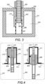
- Figure 3 is a schematic diagram showing a cross-section side view of another example implementation of a cavity arrangement in one cavity in a frequency adjustable filter.
- Figure 3 uses the same reference numbers as Figure 2 , and depicts the same portion of the cavity arrangement as Figure 2 .
- the cavity arrangement of Figure 3 further comprises an integrated mechanical support structure and one or more fixed driving shafts, examples being described below with Figures 4 to 6 .
- the cavity arrangement differs from the one illustrated in Figure 2 in that respect that the upper end cover 211' of the first cylinder 205' has the second hole but no third hole, and the first hole 204' in the lid 203' is dimensioned to allow the adjusting bar 208 to extend to the cavity but not to accommodate the actuator 209 resulting that the actuator 209 will remain above the upper face of the lid 203.
- the second hole has the common vertical axis (not illustrated in Figure 3 ) with the first hole 204.
- the first cylinder 205' and the lid 203' have been made out of one piece of material, just to illustrate that such solutions can be implemented with any of the examples illustrated herein. It should be appreciated that the first cylinder 205' and the lid 203' may also be made of separate pieces of material.
- first cylinder has no upper end cover, and the first hole is dimensioned as in Figure 3 , or the lid comprises two holes, dimensioned as the second and third hole in the example of Figure 2 so that part of the lid will accommodate the actuator.
- Figure 4 is a schematic diagram showing a cross-section of an example of the integrated support structure, a fixed driving shaft, the actuator and the adjusting bar.
- Figure 4 uses the same reference numbers as Figures 2 and 3 .
- the actuator 209 and the adjusting bar 208 are illustrated in extreme positions 401, 402, their position being adjustable between the extreme positions.
- the support structure (integrated support structure) 411 is a mechanical support structure 411 that is attached to the lid, arranged on the upper surface 203'of the lid above the cavity.
- the support structure may be a ⁇ -shaped metallic structure, or a cylinder-shaped structure, or a stool-like structure with 3 or 4 legs, made of sheet metal, for example.
- a stool-like support structure may be formed by using two ⁇ -shaped metallic structures with a 90 degrees shift between them, the two structures sharing the same vertical axis.
- the support structure may be shaped differently.
- the support structure 411 may be mechanically attached to the lid at several positions.
- the support structure 411 comprises mechanical means (a mechanical adjustment mechanism) 412 attached to the support structure 411.
- the actuator position may be adjusted and maintained using the mechanical means.
- the mechanical means may be used to mechanically adjust the position of the adjusting bar in the resonator.
- the driving shaft 413 also called a drive shaft, is fixedly attached to the upper part of the mechanical support.
- the driving shaft 413 is positioned so that its central axis is the common central axis 210 (common vertical axis).
- the driving shaft 413 is arranged to move the actuator 209 and the adjustable bar 208' between the upmost position 401 and the downmost position 402. More precisely, the movable actuator 209 is arranged to move along the driving shaft 413. Since the adjusting bar 208' is attached to the actuator 209, it is arranged to move correspondingly.
- a level 414 where a bottom of the actuator 209 is at the downmost position 402 is below the upper surface of the lid.
- the adjustable bar 208' is a hollow bar, the hollow being dimensioned to allow the driving shaft 413 to enter the adjusting bar 208', i.e. the hollow in the adjusting bar, when the bar is moving towards the upmost position.
- the hollow in the bar provides a further addition to the guiding mechanism, or the guiding cavity.
- the solution is a very stable mechanical solution that allows an accurate mechanical movement of the adjusting bar. Further, the longer the guiding mechanism is, it is less likely to have increased friction due to adjustable bar tilting, and system performance under mechanical shocks and vibrations improves.
- Figures 5 and 6 illustrates different examples how to attach (integrate) the adjusting bar 208 to the actuator 209.
- Figures 5 and 6 uses the same reference numbers as Figure 4 .
- the adjusting bar 208 is attached to the bottom of the actuator 209, whereas in the example of Figure 6 , the adjusting bar 208 is attached to a side (a vertical side) of the actuator 209.
- Dimension 510 illustrates an overall height required for the driving shaft from the level 414 and dimension 511 illustrates the amount the adjustable pin and the actuator may move. By adjusting the height of the driving shaft 413, one may adjust the mechanical stroke that may be applied by the movement of the adjustable pin and the actuator.
- the overall height would be a sum of dimensions 510 and 511.
- the disclosed solutions require less space and are more compact, thereby enabling to reduce overall vertical height of the filter.
- Figure 7 is a schematic diagram showing a cross-section of an example arrangement for an adjustable frequency filter 700, comprising a cavity arrangement, an integrated support structure, a fixed driving shaft, the actuator and the adjusting bar.
- Figure 7 uses the same reference numbers as Figures 2 , 3 and 4 .
- the adjustable frequency filter 700 comprises a support structure 411' with mechanical means 412', the support structure being attached to the lid, arranged on the upper surface of the lid above the cavity, using the principles described above with Figure 4 .
- the actuator 209 and the adjusting bar 208' are illustrated in extreme positions 701, 702, their position being adjustable between the extreme positions, as described above with Figure 4 .
- Different examples for the shape of the support structure has been described above.
- the cavity 202 within the housing 201 comprises the cylinder pair of overlaying cylinders 205, 205, as described above with Figure 2 .
- the mechanical support part 722 forms part of the guiding mechanism providing a stable mechanical solution allowing accurate movement of the adjusting bar 208'. It should be appreciated that the mechanical support part 722 may be part of the upper end cover of the cylinder, or part of the lid 203.
- the lid comprises above the first hole 204", which is configured to accommodate the actuator, and the mechanical support part 722 (or at least the one requiring more space), a fourth hole 721 for facilitating positioning of the support structure 411.
- the holes and the hollow in the adjusting bar have a common vertical axis.
- Figure 8 is a schematic diagram showing a cross-section of an example cavity arrangement for an adjustable frequency filter 800.
- Figure 8 uses the same reference numbers as Figures 2 , 3 and 4 .
- the adjustable frequency filter 800 comprises the housing 201' with a first hole 804, a lid 203' without any hole, enclosing a cavity 202 forming a resonator.
- the resonator further comprises the first resonator element 205", arranged to extend from the lid 203' towards a bottom of the cavity 202, and the second resonator element 206, arranged to extend from the bottom of the cavity 202 towards the lid 203', dimensioned so that the second resonator element 206 fits inside the first resonator element 205, and hence the resonator elements 205", 206 are overlapping.
- the cavity arrangement further comprises an actuator 209' arranged to the first hole 804, which is dimensioned to accommodate the actuator 209', a driving shaft 413', and a movable adjusting bar 208'.
- the actuator 209' is not arranged to move, but to move the driving shaft 413', fixedly attached to the actuator 209'.
- Different examples of the actuator 209' are described above with Figure 2 .
- the movable adjusting bar 208' is arranged to move along the driving shaft 413'.
- the movable adjusting bare 208' is positioned to have a common vertical central axis 210 with the first resonator part 205" and the second resonator part 206.
- the movable adjusting bar 208' has a non-tubular shape, comprising a first portion 803 (a movable dielectric portion), a second portion 804 (a support portion) and a tubular shape portion 805 (movable bar portion).
- the first portion 803 is dimensioned to accommodate a space between the first resonator element 205" and the second resonator element 206 in the area in which the first resonator element and the second resonator element are overlapping.
- the second portion 804 is between and the first portion 803 and the tubular shape portion 805, which is in the middle.
- the inner surface of the first portion 803 is dimensioned to be substantially equal with the outer surface of the second resonator part 206.
- the outer surface of the first portion 803 is dimensioned to be substantially equal with the inner surface of the first resonator element 205".
- the substantially equal means that the dimensions of the first portion 803 allow the first portion to move between the resonator elements 205", 206 and yet allowing the resonator elements 205" 206, or more precisely the inner surface of the first resonator element 205" and the outer surface of the second resonator element 206, to accurately guide the vertical movement of the adjusting bar 20'8.
- an outer surface of the tubular shape portion 805 is dimensioned to be substantially equal with the inner surface of the second resonator part 206, also the tubular shape portion 805 and the second resonator part 206 provides accurate guidance to the vertical movement of the adjusting bar 208'.
- the first portion 803 is vertically dimensioned so that even in the extreme positions 801, 802 part of the first portion 803 remains between the resonator elements 205", 206, and part of it is not between the resonator elements 205", 206 but within the first resonator element 205".
- the vertical dimension of the movable dielectric element 803 is longer than the vertical dimension of the overlap of the resonator elements 205", 206.
- the adjusting bar 208' is made of dielectric material, for example a ceramic dielectric material.
- the first resonator part 205" and part of the second resonator part 206 form the guiding mechanism providing a stable mechanical solution allowing accurate movement of the adjusting bar 208'.
- the total length of the first resonator part 205" can be used for guiding the mechanical movement and the arrangement has a reduced stroke.
- the reduced stroke with the length of the integrated guidance allows a robust and flexible design and minimizes mechanical drawbacks that arrangements with non-reduced stroke and non-integrated guidance have.
- Figure 8 the adjusting bar 208' is illustrated in extreme positions 801, 802, the position being adjustable between the extreme positions by mechanical means using the actuator, as will be described below with Figures 9 and 10 disclosing a portion of the cavity arrangement.
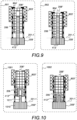
- Figure 9 illustrates an example in which the actuator is a direct linear motor
- Figure 10 an example in which the actuator is a stepper motor.
- Figures 9 and 10 illustrate alternative solutions how to provide the non-tubular shape adjusting bar, i.e. how to have the dielectric portion between the first and second resonator elements. It should be appreciated that any of the solutions may be used with any of the examples illustrated with Figures 8 to 10 .
- the non-tubular shape adjusting bar is formed by separate pieces of a movable dielectric element 803', a support structure 804' and a movable bar 208".
- the different portions of Figure 8 of the adjusting bar are implemented using separate pieces.
- the movable dielectric element 803' may be made of the ceramic dielectric material and dimensioned in a similar way as the first portion described above with Figure 8 .
- the movable bar 208" may be a hollow bar, made of metal or plastic or dielectric material, or comprise metallic material and/or plastic and/or dielectric material.
- An example of plastic is polyamide.
- the movable bar 208" is dimensioned to be substantially equal with the minimum horizontal dimension of the hollow 207, which in the example of Figure 9 is defined by the inner surface of the second cylinder 206.
- the substantially equal means that the movable bar 208" has a dimension allowing the movable bar 208" to move within the second resonator element 206 and yet allowing the second resonator element 206, or more precisely its inner surface, to accurately guide the vertical movement of the movable bar 208", and hence the vertical movement of the movable dielectric element 803'.
- the movable bar 208" is dimensioned so that the second resonator element 206 forms part of the guiding mechanism, the movable dielectric part 803' may be dimensioned to be thinner than described above with Figure 8 .
- the support structure 804' is attached to the movable dielectric element 803' and to the adjusting bar 208" to connect them and thereby to move the movable dielectric element 803' according to the movement of the movable bar 208".
- the support structure 804' may be made of metal or plastic or dielectric material, or comprise metallic material and/or plastic and/or dielectric material. It should be appreciated that the support structure may have any other shape than the one illustrated.
- the non-tubular shape adjusting bar may comprise a movable ceramic dielectric element 803', a plastic support structure 804' and a metallic movable bar 208". If the movable bar 208" and the support structure 804' are made of same material, the support structure 804' may form part of the movable bar 208", i.e. they form together one piece.
- the direct linear motor 209' is attached to the housing (not illustrated in Figure 9 ) at the bottom of the cavity, preferably such that its upper surface is on the same level as the upper surface 201-1 of the bottom of the cavity, and the second resonator element 206 is arranged on the upper surface of the direct linear motor 209'.
- the driving shaft 413' is fixedly attached to the direct linear motor 209', and a linear movement of the driving shaft 413' moves the movable bar 208", and thereby the movable dielectric element 803' between the upmost position 901 and the downmost position 902.
- the movable bar 208" is a hollow bar, the hollow being dimensioned to allow the driving shaft 413' to enter the movable bar 208", i.e. the hollow in the bar, when the bar is moving towards the downmost position.
- the hollow provides a further guiding to the guiding provided by the second resonator element 206, and the first resonator element if the movable dielectric element is dimensioned as described with Figure 8 .
- the driving shaft and the hollow in the bar have a common vertical axis with the resonator elements.
- the non-tubular shape adjusting bar is formed by separate pieces of a movable dielectric element 803" having a support extension and a movable bar 208".
- the movable dielectric element 803" may be made of the ceramic dielectric material and a portion moving between the resonator elements may be dimensioned in a similar way as the first portion described above with Figure 8 .
- the support extension may have any other shape than the one illustrated.
- the movable bar 208" may be dimensioned as described above with Figure 9 , and it may be made of materials described above with Figure 9 .
- the stepper motor 209" has a motor part 1010 and a screw part 1011, the screw part 1011 extending upward from the upper surface of the motor part 1010.
- the stepper motor 209" is attached to the housing (not illustrated in Figure 9 ) at the bottom of the cavity, preferably such that the upper surface of the motor part is on the same level as the upper surface 201-1 of the bottom of the cavity.
- the second resonator element 206 is arranged on the upper surface of the motor part of the stepper motor 209".
- a shaft 413" is rotatable fixedly attached to the stepper motor 209" to rotate around the screw part 1011.
- the screw part 1011, or the screw part 1011 and the shaft 413" form the driving shaft along which the movable bar 208" is arranged to move, thereby also moving the dielectric movable element 803".
- the screw part 1011 and the shaft 413" may be made of metal.
- the adjustable bar 208' is a hollow bar, the hollow being dimensioned to accommodate the shaft 413" so that the adjustable bar 208' will move as the shaft 413" moves.
- the stepper motor 209" creates the linear motion by rotating the shaft 413" along the screw part 1011 thereby moving the bar 208" and the movable dielectric element 803" between the upmost position 1001 and the downmost position 1002.
- the shaft 413" provides a side support to the screw part 1011, the side support stopping the screw part 1011 from rotating around itself and making the linear motion possible. Further, the inner surface of the second resonator element 206 and the outer surface of the bar 208" may be at least partly threaded to allow the rotating movement.
- the stepper motor allows to maintain a resolution of the vertical movement constant.
- the stepper motor may be arranged to make multiple steps per turn and do micro-stepping, which further increase the resolution.
- the resolution can further be increased by adding a gearbox to the arrangement.
- the stepper motor also has some holding force even without current, thereby reducing power consumption and making the adjusting bar resilient to large movements caused by shocks and vibrations.
- the size of the actuator, and hence the outer horizontal dimension of the first hole accommodating the actuator is larger than the outer horizontal dimension of the second resonator, that may always not be the case.
- the outer horizontal dimension of the first hole may be equal to the outer horizontal dimension of the second resonator, still allowing the second resonator element being arranged on the upper surface of the actuator.
- the outer horizontal dimension of the first hole is smaller than the inner horizontal dimension of the second resonator, in which case the second resonator element is arranged on the upper surface of the bottom of the cavity.
- the movable adjusting bar's penetration stroke is comparable to the height of the resonator, and thereby the disclosed examples provide a compact mechanism to tune a frequency adjustable filter.
- the tuning occurs by the first portion, or by the dielectric movable element taking advantage of the high capacitance area, and hence for the same tuning range the mechanical stroke is smaller than a mechanical stroke needed by the metallic adjusting bar in the examples of Figures 2 to 7 .
- the tuning range obtainable by the examples of Figures 8 to 10 is bigger than in the examples of Figures 2 to 7 .
- Figure 11 illustrates a further possibility to increase a tuning range of any of the above described examples.
- a hollow of the smaller of the first and second resonator elements in the example the hollow 207' of the second resonator element 206 extending from the bottom is partially filled with a dielectric material 1101, for example with polytetrafluoroethylene.
- adjusting/tuning mechanisms to resonators in frequency adjustable filters are disclosed, the adjusting mechanisms using a movable adjusting bar arranged to move within overlapping resonator elements.
- the movable adjusting bar being moved by the actuator through the first hole by means of the driving shaft.
- a fixed driving shaft moves the actuator at least within the first hole, and thereby the movable actuator, or the actuator is arranged to the first hole, and a driving shaft fixed to the actuator moves the movable adjusting bar.
- the above disclosed examples provide a frequency adjustable filter with a wide tuning range, as are shown by simulation results in Figure 12 obtained from an adjustable filter having five resonators according to the example of Figure 7 . More precisely, in the simulations, five adjusting bars (one per resonator) that are movable separately to new positions between the two extreme positions are used. The different frequencies in Figure 12 correspond to the different positions of the adjusting bars for all the five resonators.
- Figure 13 illustrates an apparatus comprising a communication controller 1310 such as at least one processor or processing circuitry, and at least one memory 1320 including a computer program code (software, algorithm) ALG. 1321, wherein the at least one memory and the computer program code (software, algorithm) are configured, with the at least one processor, to cause the apparatus to carry out at least filtering of transmissions using one or more frequency adjustable filters 1331 according to any one of the embodiments, examples and implementations described above.
- the apparatus 1300 may be, for example a base station or an access node, a user equipment, or terminal device in a vehicle, or any electronic device, examples being listed above with Figure 1 .
- the memory 1320 may be implemented using any suitable data storage technology, such as semiconductor based memory devices, flash memory, magnetic memory devices and systems, optical memory devices and systems, fixed memory and removable memory.
- the memory may comprise a configuration storage CONF. 1321, such as a configuration database
- the memory 1320 may further store other data, such as a data buffer for data waiting to be processed (including transmission).
- the apparatus comprises a communication interface 1330 comprising hardware and/or software for realizing communication connectivity according to one or more wireless and/or wired communication protocols.
- the communication interface 1330 may provide the apparatus with radio communication capabilities, as well as communication capabilities towards core network.
- the communication interface 1330 comprises one or more frequency adaptable filters 1331, according to any one of the embodiments, examples and implementations described above
- the communication interface 1330 may further comprise standard well-known components such as an amplifier, filter, frequency-converter, (de)modulator, and encoder/decoder circuitries and, in case wireless communication is supported, one or more antennas.
- the communication controller may comprise an electrical circuitry for controlling and/or adapting the one or more frequency adaptable filters 1331.
- circuitry refers to all of the following: (a) hardware-only circuit implementations, such as implementations in only analog and/or digital circuitry, and (b) combinations of circuits and soft-ware (and/or firmware), such as (as applicable): (i) a combination of processor(s) or (ii) portions of processor(s)/software including digital signal processor(s), software, and memory(ies) that work together to cause an apparatus to perform various functions, and (c) circuits, such as a microprocessor(s) or a portion of a microprocessor(s), that require software or firmware for operation, even if the software or firmware is not physically present.
- This definition of 'circuitry' applies to all uses of this term in this application.
- the term 'circuitry' would also cover an implementation of merely a processor (or multiple processors) or a portion of a processor and its (or their) accompanying soft-ware and/or firmware.
- the term 'circuitry' would also cover, for example and if applicable to the particular element, a baseband integrated circuit or applications processor integrated circuit for a mobile phone or a similar integrated circuit in a server, a cellular network device, or another network device.
Landscapes
- Physics & Mathematics (AREA)
- Electromagnetism (AREA)
- Control Of Motors That Do Not Use Commutators (AREA)
Abstract
Description
- Various example embodiments relate to wireless communications, and especially to frequency adjustable filters.
- Wireless communication systems are under constant development. In the long term, more spectrum will be needed to maintain quality of service and meet growing demand. Frequency adjustable filters facilitate to achieve efficient use of the spectrum in use.
- Independent claims define the scope of protection. The exemplary embodiments and features, if any, described in this specification that do not fall under the scope of the independent claims are to be interpreted as examples useful for understanding various implementation examples.
- According to an aspect there is provided a frequency adjustable filter comprising at least a housing, which comprises one or more cavities closed by a lid above the housing, the frequency adjustable filter comprising, per a cavity forming a resonator, at least: a first resonator element extending from the lid towards a bottom of the cavity on an opposite side of the lid; a second resonator element extending from the bottom towards the lid, the second resonator element partially overlapping the first resonator element; an adjusting bar extending inside an area in which the first resonator element and the second resonator element are overlapping, the adjusting bar being arranged to move within said area; a first hole either in the lid or in the bottom; a driving shaft; and an actuator arranged to move the adjusting bar through the first hole by means of the driving shaft, wherein at least the first resonator element, the second resonator element and the adjusting bar are positioned to have a common vertical central axis.
- In embodiments, the first resonator element is a first cylinder and the second resonator element is a second cylinder, one of the first and second cylinders extending inside the other one of the first and second cylinders.
- In embodiments, the first cylinder and the second cylinder are metallic cylinders.
- In embodiments, the frequency adjustable filter further comprises, per the cavity forming the resonator, when the first hole is in the lid, a support structure attached to the lid, arranged on the upper surface of the lid above the cavity, wherein the driving shaft is fixedly attached to the support structure; the actuator is a movable actuator arranged to move along the driving shaft; and the adjusting bar is attached to the actuator to move as the actuator move.
- In embodiments, where the first hole is in the lid, the movable actuator comprises a second hole for the driving shaft; and the adjusting bar is attached to the bottom part of the movable actuator and comprises a hollow to accommodate the driving shaft, wherein the first hole, the second hole, and the movable actuator are positioned to have a common vertical central axis with the first resonator element, the second resonator element and the adjusting bar.
- In embodiments, where the first hole is in the lid, the movable actuator comprises a second hole for the driving shaft; and the adjusting bar is attached to a vertical side of the movable actuator.
- In embodiments, where the first hole is in the lid, the first resonator element has an upper end cover comprising a third hole through which the adjustable bar extends inside the area in which the first resonator element and the second resonator element are overlapping, the third hole having a common central axis with the first hole.
- In embodiments, where the first hole is in the lid, the first hole in the lid is dimensioned to accommodate the actuator and the adjusting bar attached to the actuator; and the upper end cover comprises a fourth hole between the first hole in the lid and the third hole, the fourth hole being dimensioned to accommodate the actuator and the adjusting bar attached to the actuator.
- In embodiments, where the first hole is in the lid, the frequency adjustable filter further comprises mechanical means for adjusting the position of the adjusting bar inside the area in which the first resonator element and the second resonator element are overlapping, the mechanical means being attached to the support structure.
- In embodiments, where the first hole is in the bottom, the adjusting bar comprises a movable bar portion, a movable dielectric portion between the first resonator element and the second resonator element in the area in which the first resonator element and the second resonator element are overlapping, and a support portion between the movable bar portion and the movable dielectric portion, to move the movable dielectric portion according to the movement of the movable bar portion; the driving shaft is fixedly attached to the actuator; the first hole is dimensioned to accommodate the actuator; and the movable bar is arranged to move along the driving shaft.
- In embodiments, where the first hole is in the bottom, an outer horizontal cross section of the movable bar portion is dimensioned to be substantially equal to an inner horizontal cross section of the second resonator element.
- In embodiments, where the first hole is in the bottom, the movable dielectric portion is a movable dielectric element, the movable bar portion is a movable bar, and the support portion is a support structure attached to the movable dielectric element and the movable bar or the support portion is part of the movable dielectric element or part of the movable bar.
- In embodiments, where the first hole is in the bottom, the support portion is made of plastic and/or the movable bar portion is made of plastic.
- According to an aspect there is provided an apparatus comprising a plurality of frequency adjustable filters; at least one processor; and at least one memory including computer program code, the at least one memory and computer program code configured to, with the at least one processor, cause the apparatus at least to perform: filtering transmission over a radio interface using said plurality of frequency adjustable filters, wherein a frequency adjustable filter comprises at least a housing comprising one or more cavities closed by a lid above the housing, the frequency adjustable filter comprising, per a cavity forming a resonator, at least: a first resonator element extending from the lid towards a bottom of the cavity on an opposite side of the lid; a second resonator element extending from the bottom towards the lid, the second resonator element partially overlapping the first resonator element; an adjusting bar extending inside an area in which the first resonator element and the second resonator element are overlapping, the adjusting bar being arranged to move within said area; a first hole either in the lid or in the bottom; a driving shaft; and an actuator arranged to move the adjusting bar through the first hole by means of the driving shaft, wherein at least the first resonator element, the second resonator element and the adjusting bar are positioned to have a common vertical central axis.
- In an embodiment of the apparatus, the movable actuator comprises a second hole for the driving shaft.
- Embodiments are described below, by way of example only, with reference to the accompanying drawings, in which
-
Figure 1 illustrates an exemplified wireless communication system; -
Figures 2 to 11 are schematic block diagrams showing different cross section views; -
Figure12 shows simulation results; and -
Figure 13 is a schematic block diagram. - The following embodiments are examples. Although the specification may refer to "an", "one", or "some" embodiment(s) in several locations, this does not necessarily mean that each such reference is to the same embodiment(s), or that the feature only applies to a single embodiment. Single features of different embodiments may also be combined to provide other embodiments. Furthermore, words "comprising" and "including" should be understood as not limiting the described embodiments to consist of only those features that have been mentioned and such embodiments may contain also features/structures that have not been specifically mentioned. Further, although terms including ordinal numbers, such as "first", "second", etc., may be used for describing various elements, the structural elements are not restricted by the terms. The terms are used merely for the purpose of distinguishing an element from other elements. For example, a first signal could be termed a second signal, and similarly, a second signal could be also termed a first signal without departing from the scope of the present disclosure.
- In the following, different exemplifying embodiments will be described using, as an example of an access architecture to which the embodiments may be applied, a radio access architecture based on long term evolution advanced (LTE Advanced, LTE-A) or new radio (NR, 5G), without restricting the embodiments to such an architecture, however. The embodiments may also be applied to other kinds of communications networks having suitable means by adjusting parameters and procedures appropriately. Some examples of other options for suitable systems are the universal mobile telecommunications system (UMTS) radio access network (UTRAN or E-UTRAN), long term evolution (LTE, the same as E-UTRA), wireless local area network (WLAN or WiFi), worldwide interoperability for microwave access (WiMAX), BluetoothOO, personal communications services (PCS), ZigBee®, wideband code division multiple access (WCDMA), systems using ultra-wideband (UWB) technology, sensor networks, mobile ad-hoc networks (MANETs) and Internet Protocol multimedia subsystems (IMS) or any combination thereof.
-
Figure 1 depicts examples of simplified system architectures only showing some elements and functional entities, all being logical units, whose implementation may differ from what is shown. The connections shown inFigure 1 are logical connections; the actual physical connections may be different. It is apparent to a person skilled in the art that the system typically comprises also other functions and structures than those shown inFigure 1 . - The embodiments are not, however, restricted to the
system 100 given as an example but a person skilled in the art may apply the solution to other communication systems provided with necessary properties. - The example of
Figure 1 shows a part of an exemplifying radio access network. -
Figure 1 showsuser devices 101, 101' configured to be in a wireless connection on one or more communication channels with anode 102. Thenode 102 is further connected to acore network 105. In one example, thenode 102 may be an access node such as (e/g)NodeB providing or serving devices in a cell. In one example, thenode 102 may be a non-3GPP access node. The physical link from a device to a (e/g)NodeB is called uplink or reverse link and the physical link from the (e/g)NodeB to the device is called downlink or forward link. It should be appreciated that (e/g)NodeBs or their functionalities may be implemented by using any node, host, server or access point etc. entity suitable for such a usage. - A communications system typically comprises more than one (e/g)NodeB in which case the (e/g)NodeBs may also be configured to communicate with one another over links, wired or wireless, designed for the purpose. These links may be used for signaling purposes. The (e/g)NodeB is a computing device configured to control the radio resources of communication system it is coupled to. The NodeB may also be referred to as a base station, an access point or any other type of interfacing device including a relay station capable of operating in a wireless environment. The (e/g)NodeB includes or is coupled to transceivers. From the transceivers of the (e/g)NodeB, a connection is provided to an antenna unit that establishes bi-directional radio links to devices. The antenna unit may comprise a plurality of antennas or antenna elements. The (e/g)NodeB is further connected to the core network 105 (CN or next generation core NGC). Depending on the system, the counterpart on the CN side can be a serving gateway (S-GW, routing and forwarding user data packets), packet data network gateway (P-GW), for providing connectivity of user devices (UEs) to external packet data networks, or mobile management entity (MME), or access and mobility management function (AMF), etc.
- The user device (also called UE, user equipment, user terminal, terminal device, etc.) illustrates one type of an apparatus to which resources on the air interface are allocated and assigned, and thus any feature described herein with a user device may be implemented with a corresponding apparatus, such as a relay node. An example of such a relay node is a layer 3 relay (self-backhauling relay) towards the base station.
- The user device typically refers to a device ( e.g. a portable or non-portable computing device) that includes wireless mobile communication devices operating with or without a subscriber identification module (SIM), including, but not limited to, the following types of devices: a mobile station (mobile phone), smartphone, personal digital assistant (PDA), handset, device using a wireless modem (alarm or measurement device, etc.), laptop and/or touch screen computer, tablet, game console, notebook, and multimedia device. It should be appreciated that a device may also be a nearly exclusive uplink only device, of which an example is a camera or video camera loading images or video clips to a network. A device may also be a device having capability to operate in Internet of Things (IoT) network which is a scenario in which objects are provided with the ability to transfer data over a network without requiring human-to-human or human-to-computer interaction, e.g. to be used in smart power grids and connected vehicles. The user device may also utilize cloud. In some applications, a user device may comprise a user portable device with radio parts (such as a watch, earphones, eyeglasses, other wearable accessories or wearables) and the computation is carried out in the cloud. The device (or in some embodiments a layer 3 relay node) is configured to perform one or more of user equipment functionalities. The user device may also be called a subscriber unit, mobile station, remote terminal, access terminal, user terminal or user equipment (UE) just to mention but a few names or apparatuses.
- Various techniques described herein may also be applied to a cyber-physical system (CPS) (a system of collaborating computational elements controlling physical entities). CPS may enable the implementation and exploitation of massive amounts of interconnected ICT devices (sensors, actuators, processors microcontrollers, etc.) embedded in physical objects at different locations. Mobile cyber physical systems, in which the physical system in question has inherent mobility, are a subcategory of cyber-physical systems. Examples of mobile physical systems include mobile robotics and electronics transported by humans or animals.
- Additionally, although the apparatuses have been depicted as single entities, different units, processors and/or memory units (not all shown in
Figure 1 ) may be implemented. - 5G enables using multiple input - multiple output (MIMO) antennas, many more base stations or nodes than the LTE (a so-called small cell concept), including macro sites operating in co-operation with smaller stations and employing a variety of radio technologies depending on service needs, use cases and/or spectrum available. 5G mobile communications supports a wide range of use cases and related applications including video streaming, augmented reality, different ways of data sharing and various forms of machine type applications (such as (massive) machine-type communications (mMTC), including vehicular safety, different sensors and real-time control. 5G is expected to have multiple radio interfaces, namely below 6GHz, cmWave and mmWave, and also being integrable with existing legacy radio access technologies, such as the LTE. Integration with the LTE may be implemented, at least in the early phase, as a system, where macro coverage is provided by the LTE and 5G radio interface access comes from small cells by aggregation to the LTE. In other words, 5G is planned to support both inter-RAT operability (such as LTE-5G) and inter-RI operability (inter-radio interface operability, such as below 6GHz - cmWave, below 6GHz - cmWave - mmWave). One of the concepts considered to be used in 5G networks is network slicing in which multiple independent and dedicated virtual sub-networks (network instances) may be created within the same infrastructure to run services that have different requirements on latency, reliability, throughput and mobility.
- The current architecture in LTE networks is fully distributed in the radio and fully centralized in the core network. The low latency applications and services in 5G require to bring the content close to the radio which leads to local break out and multi-access edge computing (MEC). 5G enables analytics and knowledge generation to occur at the source of the data. This approach requires leveraging resources that may not be continuously connected to a network such as laptops, smartphones, tablets and sensors. MEC provides a distributed computing environment for application and service hosting. It also has the ability to store and process content in close proximity to cellular subscribers for faster response time. Edge computing covers a wide range of technologies such as wireless sensor networks, mobile data acquisition, mobile signature analysis, cooperative distributed peer-to-peer ad hoc networking and processing also classifiable as local cloud/fog computing and grid/mesh computing, dew computing, mobile edge computing, cloud-let, distributed data storage and retrieval, autonomic self-healing networks, remote cloud services, augmented and virtual reality, data caching, Internet of Things (massive connectivity and/or latency critical), critical communications (autonomous vehicles, traffic safety, real-time analytics, time-critical control, healthcare applications).
- The communication system is also able to communicate with other networks, such as a public switched telephone network or the
Internet 106, or utilize services provided by them. The communication network may also be able to support the usage of cloud services, for example at least part of core network operations may be carried out as a cloud service (this is depicted inFigure 1 by "cloud" 107). The communication system may also comprise a central control entity, or a like, providing facilities for networks of different operators to cooperate for example in spectrum sharing. - The technology of Edge cloud may be brought into a radio access network (RAN) by utilizing network function virtualization (NVF) and software defined networking (SDN). Using the technology of edge cloud may mean access node operations to be carried out, at least partly, in a server, host or node operationally coupled to a remote radio head or base station comprising radio parts. It is also possible that node operations will be distributed among a plurality of servers, nodes or hosts. Application of cloudRAN architecture enables RAN real time functions being carried out at the RAN side (in a distributed unit, DU 102) and non-real time functions being carried out in a centralized manner (in a centralized unit, CU 104).
- It should also be understood that the distribution of labour between core network operations and base station operations may differ from that of the LTE or even be non-existent. Some other technology advancements probably to be used are Big Data and all-IP, which may change the way networks are being constructed and managed. 5G (or new radio, NR) networks are being designed to support multiple hierarchies, where MEC servers can be placed between the core and the base station or nodeB (gNB). It should be appreciated that MEC can be applied in 4G networks as well.
- 5G may also utilize satellite communication to enhance or complement the coverage of 5G service, for example by providing backhauling. Possible use cases are providing service continuity for machine-to-machine (M2M) or Internet of Things (IoT) devices or for passengers on board of vehicles, or ensuring service availability for critical communications, and future railway/maritime/aeronautical communications. Satellite communication may utilize geostationary earth orbit (GEO) satellite systems, but also low earth orbit (LEO) satellite systems, in particular mega-constellations (systems in which hundreds of (nano)satellites are deployed). Each
satellite 103 in the mega-constellation may cover several satellite-enabled network entities that create on-ground cells. The on-ground cells may be created through an on-ground relay node 102 or by a gNB located on-ground or in a satellite. - It is obvious for a person skilled in the art that the depicted system is only an example of a part of a radio access system and in practice, the system may comprise a plurality of (e/g)NodeBs, the user device may have an access to a plurality of radio cells and the system may comprise also other apparatuses, such as physical layer relay nodes or other network elements, etc. At least one of the (e/g)NodeBs or may be a Home(e/g)nodeB. Additionally, in a geographical area of a radio communication system a plurality of different kinds of radio cells as well as a plurality of radio cells may be provided. Radio cells may be macro cells (or umbrella cells) which are large cells, usually having a diameter of up to tens of kilometers, or smaller cells such as micro-, femto- or picocells. The (e/g)NodeBs of
Figure 1 may provide any kind of these cells. A cellular radio system may be implemented as a multilayer network including several kinds of cells. Typically, in multilayer networks, one access node provides one kind of a cell or cells, and thus a plurality of (e/g)NodeBs are required to provide such a network structure. - For fulfilling the need for improving the deployment and performance of communication systems, the concept of "plug-and-play" (e/g)NodeBs has been introduced. Typically, a network which is able to use "plug-and-play" (e/g)Node Bs, includes, in addition to Home (e/g)NodeBs (H(e/g)nodeBs), a home node B gateway, or HNB-GW (not shown in
Figure 1 ). A HNB Gateway (HNB-GW), which is typically installed within an operator's network may aggregate traffic from a large number of HNBs back to a core network. - It is envisaged that in 5G, 6G and beyond, range of frequency bands will increase. To facilitate efficient use of the spectrum, frequency adjustable filters may be used in apparatuses. Below different examples of frequency adjustable filters, in which center frequencies of resonators are adjusted by adjusting bars penetrating within the resonators are disclosed. In other words, the fact that a resonant frequency of a resonator depends on a portion of an adjusting bar within the resonator, is utilized. Examples described below with
Figures 2 to 6 ,9 and 10 show only some portions of cavity arrangements for adjustable filters, whereasFigures 7 and8 show example arrangements for an adjustable filter. - A frequency adjustable filter comprises at least a housing and a lid above the housing, the housing comprising one or more cavities closed by the lid. In the illustrated examples, a cavity forming a resonator comprises at least two resonator elements, and at least a hole either through the lid (examples of
Figures 2 to 7 ) or through the bottom of the cavity (examples ofFigures 8 to 10 ) for adjusting frequency, i.e. for tuning the resonator. Even though in the examples one pair of resonator elements with corresponding tuning mechanism (frequency adjusting mechanism) are disclosed, it should be appreciated that a cavity may comprise a plurality of pairs of resonator elements with a plurality of tuning mechanisms. -
Figure 2 is a schematic diagram showing a cross-section side view of an example implementation of a cavity arrangement in one cavity in a frequency adjustable filter. - Referring to
Figure 2 , thecavity 202 in the frequency adjustable filter is within a housing (enclosure) 201 the frequency adjustable filter comprises and being closed by thelid 203. In the illustrated example ofFigure 2 , a resonator, formed by thecavity 202, comprises, as resonator elements (resonator parts), at least one cylinder pair of overlayingcylinders movable actuator 209 and amovable adjusting bar 208 attached to themovable actuator 209. Even though not illustrated inFigure 2 , the cavity arrangement further comprises an integrated mechanical support structure and one or more fixed driving shafts, examples being described below withFigures 4 to 6 . - The
movable adjusting bar 208 is a resonator tuner and it may be called a piston, or a pin or a rod. Theactuator 209 may be called a motor. A non-limiting list of actuators includes a direct linear motor, a stepper motor and a piezo motor. - In the illustrated example of
Figure 2 , the lid has a hole through which themovable adjusting bar 208 is extending to (penetrating) the resonator, i.e. to be within theresonator elements Figure 2 , thehole 204 in the lid, called a first hole, is dimensioned to accommodate theactuator 209 and the adjustingbar 208 attached to theactuator 209. - In the illustrated example of
Figure 2 , the resonator comprises afirst cylinder 205, arranged to extend from thelid 203 towards a bottom of thecavity 202, and asecond cylinder 206, arranged to extend from the bottom of thecavity 202 towards thelid 203, and thecylinders second cylinder 206 fits inside thefirst cylinder 205, and hence the cylinders are overlapping. Further, the cylinders are dimensioned so that the adjustingbar 208 fits inside a hollow 207, minimum horizontal dimension of the hollow 207 being defined by the inner surface. of thesecond cylinder 206. In other words, the adjustingbar 208 may move within the resonator, i.e within thefirst cylinder 205 and thesecond cylinder 206. - Further, in the illustrated example of
Figure 2 , thefirst cylinder 205 has anupper end cover 211, which may be a static, non-tunable part of the resonator. Theupper end cover 211 comprises a second hole through which theadjustable bar 208 extends to the first andsecond cylinders first hole 204 in thelid 203 and the second hole, the third hole being dimensioned to accommodate theactuator 209 and the adjustingbar 208 attached to the actuator. In the illustrated example the second hole and the third hole have the commoncentral axis 210 with thefirst hole 204. - It should be appreciated that in another implementation it may that the first cylinder is dimensioned to fit inside the second cylinder, and the inner surface of the first cylinder defines the minimum horizontal dimension of the hollow. In other words, one of the first and second cylinders extends inside the other one of the first and second cylinders to provide resonator elements within which the movable adjusting bar may move. Naturally any other kind of resonator elements allowing the movable adjusting bar to extend to and move within the resonator may be used.
- The different holes provide a guiding mechanism, or a guiding cavity, for the
adjustable bar 208, providing a stable mechanical solution allowing accurate mechanical movement of the adjustingbar 208. - In the illustrated example of
Figure 2 , thecavity 202, thehole 204 in thelid 203, theresonator elements movable adjusting bar 208 and the actuator are arranged so that they have a commonvertical axis 210. However, it should be appreciated that in another implementation, for example based on the one inFigure 6 , it is sufficient that the resonator and the adjusting bar are positioned to have the common vertical axis. - The
housing 201 and/or thelid 203, and/or theadjustable bar 208 and/or the other resonator elements, for example thecylinders housing 201 is made of metallic material, the inner metal surface of thecavity 202 is part of the resonator. -
Figure 3 is a schematic diagram showing a cross-section side view of another example implementation of a cavity arrangement in one cavity in a frequency adjustable filter.Figure 3 uses the same reference numbers asFigure 2 , and depicts the same portion of the cavity arrangement asFigure 2 . The cavity arrangement ofFigure 3 further comprises an integrated mechanical support structure and one or more fixed driving shafts, examples being described below withFigures 4 to 6 . - Referring to
Figure 3 , the cavity arrangement differs from the one illustrated inFigure 2 in that respect that the upper end cover 211' of the first cylinder 205' has the second hole but no third hole, and the first hole 204' in the lid 203' is dimensioned to allow the adjustingbar 208 to extend to the cavity but not to accommodate theactuator 209 resulting that theactuator 209 will remain above the upper face of thelid 203. In the illustrated example the second hole has the common vertical axis (not illustrated inFigure 3 ) with thefirst hole 204. Further, in the illustrated example the first cylinder 205' and the lid 203' have been made out of one piece of material, just to illustrate that such solutions can be implemented with any of the examples illustrated herein. It should be appreciated that the first cylinder 205' and the lid 203' may also be made of separate pieces of material. - Still a further possibility is that the first cylinder has no upper end cover, and the first hole is dimensioned as in
Figure 3 , or the lid comprises two holes, dimensioned as the second and third hole in the example ofFigure 2 so that part of the lid will accommodate the actuator. -
Figure 4 is a schematic diagram showing a cross-section of an example of the integrated support structure, a fixed driving shaft, the actuator and the adjusting bar.Figure 4 uses the same reference numbers asFigures 2 and3 . - In
Figure 4 , theactuator 209 and the adjustingbar 208 are illustrated inextreme positions - Referring to
Figure 4 , the support structure (integrated support structure) 411 is amechanical support structure 411 that is attached to the lid, arranged on the upper surface 203'of the lid above the cavity. The support structure may be a π-shaped metallic structure, or a cylinder-shaped structure, or a stool-like structure with 3 or 4 legs, made of sheet metal, for example. For example, a stool-like support structure may be formed by using two π-shaped metallic structures with a 90 degrees shift between them, the two structures sharing the same vertical axis. Naturally the support structure may be shaped differently. Thesupport structure 411 may be mechanically attached to the lid at several positions. - In the illustrated example of
Figure 4 , thesupport structure 411 comprises mechanical means (a mechanical adjustment mechanism) 412 attached to thesupport structure 411. The actuator position may be adjusted and maintained using the mechanical means. In other words, the mechanical means may be used to mechanically adjust the position of the adjusting bar in the resonator. - In the illustrated example of
Figure 4 , the drivingshaft 413, also called a drive shaft, is fixedly attached to the upper part of the mechanical support. In the illustrated example ofFigure 4 , the drivingshaft 413 is positioned so that its central axis is the common central axis 210 (common vertical axis). The drivingshaft 413 is arranged to move theactuator 209 and the adjustable bar 208' between theupmost position 401 and thedownmost position 402. More precisely, themovable actuator 209 is arranged to move along the drivingshaft 413. Since the adjusting bar 208' is attached to theactuator 209, it is arranged to move correspondingly. In the illustrated example ofFigure 4 , alevel 414 where a bottom of theactuator 209 is at thedownmost position 402 is below the upper surface of the lid. - In the example of
Figure 4 , the adjustable bar 208' is a hollow bar, the hollow being dimensioned to allow the drivingshaft 413 to enter the adjusting bar 208', i.e. the hollow in the adjusting bar, when the bar is moving towards the upmost position. The hollow in the bar provides a further addition to the guiding mechanism, or the guiding cavity. The solution is a very stable mechanical solution that allows an accurate mechanical movement of the adjusting bar. Further, the longer the guiding mechanism is, it is less likely to have increased friction due to adjustable bar tilting, and system performance under mechanical shocks and vibrations improves. - It should be appreciated that in other implementations, in addition to the mechanical means, or instead of the mechanical means, electronical circuitry controlling the movement of the actuator along the driving shaft may used for the same purpose.
-
Figures 5 and 6 illustrates different examples how to attach (integrate) the adjustingbar 208 to theactuator 209.Figures 5 and 6 uses the same reference numbers asFigure 4 . In the example ofFigure 5 , the adjustingbar 208 is attached to the bottom of theactuator 209, whereas in the example ofFigure 6 , the adjustingbar 208 is attached to a side (a vertical side) of theactuator 209.Dimension 510 illustrates an overall height required for the driving shaft from thelevel 414 anddimension 511 illustrates the amount the adjustable pin and the actuator may move. By adjusting the height of the drivingshaft 413, one may adjust the mechanical stroke that may be applied by the movement of the adjustable pin and the actuator. - Should the adjustable pin be attached to the driving shaft, the overall height would be a sum of
dimensions -
Figure 7 is a schematic diagram showing a cross-section of an example arrangement for anadjustable frequency filter 700, comprising a cavity arrangement, an integrated support structure, a fixed driving shaft, the actuator and the adjusting bar.Figure 7 uses the same reference numbers asFigures 2 ,3 and 4 . - Referring to
Figure 7 , theadjustable frequency filter 700 comprises a support structure 411' with mechanical means 412', the support structure being attached to the lid, arranged on the upper surface of the lid above the cavity, using the principles described above withFigure 4 . InFigure 7 , theactuator 209 and the adjusting bar 208' are illustrated inextreme positions Figure 4 . Different examples for the shape of the support structure has been described above. - In the example of
Figure 7 , thecavity 202 within thehousing 201 comprises the cylinder pair of overlayingcylinders Figure 2 . However, in the examples ofFigure 7 , above theupper end cover 211 there is a separatemechanical support part 722 for supporting movement of the adjusting bar 208' and for supporting theactuator 209. Themechanical support part 722 forms part of the guiding mechanism providing a stable mechanical solution allowing accurate movement of the adjusting bar 208'. It should be appreciated that themechanical support part 722 may be part of the upper end cover of the cylinder, or part of thelid 203. - In the example of
Figure 7 , the lid comprises above thefirst hole 204", which is configured to accommodate the actuator, and the mechanical support part 722 (or at least the one requiring more space), afourth hole 721 for facilitating positioning of thesupport structure 411. Even though not separately illustrated inFigure 7 , the holes and the hollow in the adjusting bar have a common vertical axis. - However, it should be appreciated that any of the above described cavity arrangement to accommodate and guide the adjusting bar, or to accommodate and guide the actuator and the adjusting bar, could be used as well.
-
Figure 8 is a schematic diagram showing a cross-section of an example cavity arrangement for anadjustable frequency filter 800.Figure 8 uses the same reference numbers asFigures 2 ,3 and 4 . - Referring to
Figure 8 , theadjustable frequency filter 800 comprises the housing 201' with afirst hole 804, a lid 203' without any hole, enclosing acavity 202 forming a resonator. The resonator further comprises thefirst resonator element 205", arranged to extend from the lid 203' towards a bottom of thecavity 202, and thesecond resonator element 206, arranged to extend from the bottom of thecavity 202 towards the lid 203', dimensioned so that thesecond resonator element 206 fits inside thefirst resonator element 205, and hence theresonator elements 205", 206 are overlapping. Different examples of the resonator element are disclosed above withFigures 2 and3 . The cavity arrangement further comprises an actuator 209' arranged to thefirst hole 804, which is dimensioned to accommodate the actuator 209', a driving shaft 413', and a movable adjusting bar 208'. - Unlike in the previous examples, in the example of
Figure 8 the actuator 209' is not arranged to move, but to move the driving shaft 413', fixedly attached to the actuator 209'. Different examples of the actuator 209' are described above withFigure 2 . - In the illustrated example of
Figure 8 , the movable adjusting bar 208' is arranged to move along the driving shaft 413'. The movable adjusting bare 208' is positioned to have a common verticalcentral axis 210 with thefirst resonator part 205" and thesecond resonator part 206. In the illustrated example, the movable adjusting bar 208' has a non-tubular shape, comprising a first portion 803 (a movable dielectric portion), a second portion 804 (a support portion) and a tubular shape portion 805 (movable bar portion). Thefirst portion 803 is dimensioned to accommodate a space between thefirst resonator element 205" and thesecond resonator element 206 in the area in which the first resonator element and the second resonator element are overlapping. Thesecond portion 804 is between and thefirst portion 803 and thetubular shape portion 805, which is in the middle. The inner surface of thefirst portion 803 is dimensioned to be substantially equal with the outer surface of thesecond resonator part 206. Correspondingly, the outer surface of thefirst portion 803 is dimensioned to be substantially equal with the inner surface of thefirst resonator element 205". The substantially equal means that the dimensions of thefirst portion 803 allow the first portion to move between theresonator elements 205", 206 and yet allowing theresonator elements 205" 206, or more precisely the inner surface of thefirst resonator element 205" and the outer surface of thesecond resonator element 206, to accurately guide the vertical movement of the adjusting bar 20'8. In case an outer surface of thetubular shape portion 805 is dimensioned to be substantially equal with the inner surface of thesecond resonator part 206, also thetubular shape portion 805 and thesecond resonator part 206 provides accurate guidance to the vertical movement of the adjusting bar 208'. - Further, in the illustrated example the
first portion 803 is vertically dimensioned so that even in theextreme positions first portion 803 remains between theresonator elements 205", 206, and part of it is not between theresonator elements 205", 206 but within thefirst resonator element 205". In other words, the vertical dimension of the movabledielectric element 803 is longer than the vertical dimension of the overlap of theresonator elements 205", 206. - In the example, the adjusting bar 208' is made of dielectric material, for example a ceramic dielectric material. By introducing the dielectric material in the
first portion 803 in the area of high capacitance, a resonant frequency of the resonator is significantly affected, and one may say that the movement of thefirst portion 803 performs the tuning. This allows to change a resonant frequency significantly with a minimum mechanical stroke. A further advantage is that there is no need to connect the tuning element and tuning mechanisms to ground, and hence no additional components to connect to the ground are needed. - In the example of
Figure 8 , thefirst resonator part 205" and part of thesecond resonator part 206 form the guiding mechanism providing a stable mechanical solution allowing accurate movement of the adjusting bar 208'. As can be seen fromFigure 8 , in the arrangement the total length of thefirst resonator part 205" can be used for guiding the mechanical movement and the arrangement has a reduced stroke. The reduced stroke with the length of the integrated guidance allows a robust and flexible design and minimizes mechanical drawbacks that arrangements with non-reduced stroke and non-integrated guidance have. - In
Figure 8 , the adjusting bar 208' is illustrated inextreme positions Figures 9 and 10 disclosing a portion of the cavity arrangement.Figure 9 illustrates an example in which the actuator is a direct linear motor, andFigure 10 an example in which the actuator is a stepper motor. Further,Figures 9 and 10 illustrate alternative solutions how to provide the non-tubular shape adjusting bar, i.e. how to have the dielectric portion between the first and second resonator elements. It should be appreciated that any of the solutions may be used with any of the examples illustrated withFigures 8 to 10 . - As can be seen from
Figure 8 , integrating the tuning mechanism into the cavity and the housing reduces the overall vertical height, even compared to implementations illustrated by means ofFigures 2 to 7 . The same applies to examples ofFigures 9 and 10 . - In the example illustrated in
Figure 9 , the non-tubular shape adjusting bar is formed by separate pieces of a movable dielectric element 803', a support structure 804' and amovable bar 208". In other words, the different portions ofFigure 8 of the adjusting bar are implemented using separate pieces. - The movable dielectric element 803' may be made of the ceramic dielectric material and dimensioned in a similar way as the first portion described above with
Figure 8 . - The
movable bar 208" may be a hollow bar, made of metal or plastic or dielectric material, or comprise metallic material and/or plastic and/or dielectric material. An example of plastic is polyamide. In the illustrated example, themovable bar 208" is dimensioned to be substantially equal with the minimum horizontal dimension of the hollow 207, which in the example ofFigure 9 is defined by the inner surface of thesecond cylinder 206. A plastic movable bar, compared to a metallic movable bar, weighs less and slides better with less friction against the inner surface of theresonator element 206, for example. The substantially equal means that themovable bar 208" has a dimension allowing themovable bar 208" to move within thesecond resonator element 206 and yet allowing thesecond resonator element 206, or more precisely its inner surface, to accurately guide the vertical movement of themovable bar 208", and hence the vertical movement of the movable dielectric element 803'. When themovable bar 208" is dimensioned so that thesecond resonator element 206 forms part of the guiding mechanism, the movable dielectric part 803' may be dimensioned to be thinner than described above withFigure 8 . - The support structure 804' is attached to the movable dielectric element 803' and to the adjusting
bar 208" to connect them and thereby to move the movable dielectric element 803' according to the movement of themovable bar 208". The support structure 804' may be made of metal or plastic or dielectric material, or comprise metallic material and/or plastic and/or dielectric material. It should be appreciated that the support structure may have any other shape than the one illustrated. - For example, the non-tubular shape adjusting bar may comprise a movable ceramic dielectric element 803', a plastic support structure 804' and a metallic
movable bar 208". If themovable bar 208" and the support structure 804' are made of same material, the support structure 804' may form part of themovable bar 208", i.e. they form together one piece. - In the example of
Figure 9 , the direct linear motor 209' is attached to the housing (not illustrated inFigure 9 ) at the bottom of the cavity, preferably such that its upper surface is on the same level as the upper surface 201-1 of the bottom of the cavity, and thesecond resonator element 206 is arranged on the upper surface of the direct linear motor 209'. The driving shaft 413' is fixedly attached to the direct linear motor 209', and a linear movement of the driving shaft 413' moves themovable bar 208", and thereby the movable dielectric element 803' between theupmost position 901 and thedownmost position 902. As said above, themovable bar 208" is a hollow bar, the hollow being dimensioned to allow the driving shaft 413' to enter themovable bar 208", i.e. the hollow in the bar, when the bar is moving towards the downmost position. The hollow provides a further guiding to the guiding provided by thesecond resonator element 206, and the first resonator element if the movable dielectric element is dimensioned as described withFigure 8 . - Even though not separately illustrated in
Figure 9 , the driving shaft and the hollow in the bar have a common vertical axis with the resonator elements. - Referring to
Figure 10 , the non-tubular shape adjusting bar is formed by separate pieces of a movabledielectric element 803" having a support extension and amovable bar 208". The movabledielectric element 803" may be made of the ceramic dielectric material and a portion moving between the resonator elements may be dimensioned in a similar way as the first portion described above withFigure 8 . It should be appreciated that the support extension may have any other shape than the one illustrated. Themovable bar 208" may be dimensioned as described above withFigure 9 , and it may be made of materials described above withFigure 9 . - In the example illustrated in
Figure 10 , thestepper motor 209" has amotor part 1010 and ascrew part 1011, thescrew part 1011 extending upward from the upper surface of themotor part 1010. Thestepper motor 209" is attached to the housing (not illustrated inFigure 9 ) at the bottom of the cavity, preferably such that the upper surface of the motor part is on the same level as the upper surface 201-1 of the bottom of the cavity. Thesecond resonator element 206 is arranged on the upper surface of the motor part of thestepper motor 209". Ashaft 413" is rotatable fixedly attached to thestepper motor 209" to rotate around thescrew part 1011. Thescrew part 1011, or thescrew part 1011 and theshaft 413" form the driving shaft along which themovable bar 208" is arranged to move, thereby also moving the dielectricmovable element 803". Thescrew part 1011 and theshaft 413" may be made of metal. The adjustable bar 208' is a hollow bar, the hollow being dimensioned to accommodate theshaft 413" so that the adjustable bar 208' will move as theshaft 413" moves. Thestepper motor 209" creates the linear motion by rotating theshaft 413" along thescrew part 1011 thereby moving thebar 208" and the movabledielectric element 803" between theupmost position 1001 and thedownmost position 1002. Theshaft 413" provides a side support to thescrew part 1011, the side support stopping thescrew part 1011 from rotating around itself and making the linear motion possible. Further, the inner surface of thesecond resonator element 206 and the outer surface of thebar 208" may be at least partly threaded to allow the rotating movement. - Use of the stepper motor allows to maintain a resolution of the vertical movement constant. In addition, the stepper motor may be arranged to make multiple steps per turn and do micro-stepping, which further increase the resolution. The resolution can further be increased by adding a gearbox to the arrangement. Further, it is possible to store the absolute position of the adjusting bar in steps, and hence, there is no need to have closed feedback loop positioning. The stepper motor also has some holding force even without current, thereby reducing power consumption and making the adjusting bar resilient to large movements caused by shocks and vibrations.
- Even though not separately illustrated in
Figure10 , the screw part, the shaft and the adjusting bar have a common vertical axis with the resonator elements. - Even though in the above examples of
Figures 8 to 10 it is assumed that the size of the actuator, and hence the outer horizontal dimension of the first hole accommodating the actuator is larger than the outer horizontal dimension of the second resonator, that may always not be the case. The outer horizontal dimension of the first hole may be equal to the outer horizontal dimension of the second resonator, still allowing the second resonator element being arranged on the upper surface of the actuator. A further possibility is that the outer horizontal dimension of the first hole is smaller than the inner horizontal dimension of the second resonator, in which case the second resonator element is arranged on the upper surface of the bottom of the cavity. - In the above examples, the movable adjusting bar's penetration stroke is comparable to the height of the resonator, and thereby the disclosed examples provide a compact mechanism to tune a frequency adjustable filter. In the example of
Figures 8, to 10 the tuning occurs by the first portion, or by the dielectric movable element taking advantage of the high capacitance area, and hence for the same tuning range the mechanical stroke is smaller than a mechanical stroke needed by the metallic adjusting bar in the examples ofFigures 2 to 7 . Correspondingly, with the same mechanical stroke, the tuning range obtainable by the examples ofFigures 8 to 10 is bigger than in the examples ofFigures 2 to 7 . - Although in the above examples, there is one driving shaft for one actuator, it should be appreciated that there may be for one actuator two or more driving shafts that are fixedly attached to the support structure, or to the actuator.
-
Figure 11 illustrates a further possibility to increase a tuning range of any of the above described examples. Referring toFigure 11 , a hollow of the smaller of the first and second resonator elements, in the example the hollow 207' of thesecond resonator element 206 extending from the bottom is partially filled with adielectric material 1101, for example with polytetrafluoroethylene. - As can be seen from the above examples, different adjusting/tuning mechanisms to resonators in frequency adjustable filters are disclosed, the adjusting mechanisms using a movable adjusting bar arranged to move within overlapping resonator elements. The movable adjusting bar being moved by the actuator through the first hole by means of the driving shaft. In other words, a fixed driving shaft moves the actuator at least within the first hole, and thereby the movable actuator, or the actuator is arranged to the first hole, and a driving shaft fixed to the actuator moves the movable adjusting bar.
- The above disclosed examples provide a frequency adjustable filter with a wide tuning range, as are shown by simulation results in
Figure 12 obtained from an adjustable filter having five resonators according to the example ofFigure 7 . More precisely, in the simulations, five adjusting bars (one per resonator) that are movable separately to new positions between the two extreme positions are used. The different frequencies inFigure 12 correspond to the different positions of the adjusting bars for all the five resonators. - As can be seen from
Figure 12 , electrical performance of the filter is not deteriorated along its tuning range, and the tuning range is a 48 % wide tuning range. S-parameters are illustrated for transmission and reflection. -
Figure 13 illustrates an apparatus comprising acommunication controller 1310 such as at least one processor or processing circuitry, and at least onememory 1320 including a computer program code (software, algorithm) ALG. 1321, wherein the at least one memory and the computer program code (software, algorithm) are configured, with the at least one processor, to cause the apparatus to carry out at least filtering of transmissions using one or more frequencyadjustable filters 1331 according to any one of the embodiments, examples and implementations described above. Theapparatus 1300 may be, for example a base station or an access node, a user equipment, or terminal device in a vehicle, or any electronic device, examples being listed above withFigure 1 . - Referring to
Figure 13 , thememory 1320 may be implemented using any suitable data storage technology, such as semiconductor based memory devices, flash memory, magnetic memory devices and systems, optical memory devices and systems, fixed memory and removable memory. The memory may comprise a configuration storage CONF. 1321, such as a configuration database Thememory 1320 may further store other data, such as a data buffer for data waiting to be processed (including transmission). - Referring to
Figure 13 , the apparatus comprises acommunication interface 1330 comprising hardware and/or software for realizing communication connectivity according to one or more wireless and/or wired communication protocols. Thecommunication interface 1330 may provide the apparatus with radio communication capabilities, as well as communication capabilities towards core network. Thecommunication interface 1330 comprises one or more frequencyadaptable filters 1331, according to any one of the embodiments, examples and implementations described above Thecommunication interface 1330 may further comprise standard well-known components such as an amplifier, filter, frequency-converter, (de)modulator, and encoder/decoder circuitries and, in case wireless communication is supported, one or more antennas. - Digital signal processing regarding transmission and reception of signals may be performed in a
communication controller 1310. The communication controller may comprise an electrical circuitry for controlling and/or adapting the one or more frequencyadaptable filters 1331. - As used in this application, the term 'circuitry' refers to all of the following: (a) hardware-only circuit implementations, such as implementations in only analog and/or digital circuitry, and (b) combinations of circuits and soft-ware (and/or firmware), such as (as applicable): (i) a combination of processor(s) or (ii) portions of processor(s)/software including digital signal processor(s), software, and memory(ies) that work together to cause an apparatus to perform various functions, and (c) circuits, such as a microprocessor(s) or a portion of a microprocessor(s), that require software or firmware for operation, even if the software or firmware is not physically present. This definition of 'circuitry' applies to all uses of this term in this application. As a further example, as used in this application, the term 'circuitry' would also cover an implementation of merely a processor (or multiple processors) or a portion of a processor and its (or their) accompanying soft-ware and/or firmware. The term 'circuitry' would also cover, for example and if applicable to the particular element, a baseband integrated circuit or applications processor integrated circuit for a mobile phone or a similar integrated circuit in a server, a cellular network device, or another network device.
- It will be obvious to a person skilled in the art that, as technology advances, the inventive concept may be implemented in various ways. The embodiments are not limited to the exemplary embodiments described above, but may vary within the scope of the claims. Therefore, all words and expressions should be interpreted broadly, and they are intended to illustrate, not to restrict, the exemplary embodiments.
Claims (15)
- A frequency adjustable filter comprising at least a housing, which comprises one or more cavities closed by a lid above the housing, the frequency adjustable filter comprising, per a cavity forming a resonator, at least:a first resonator element extending from the lid towards a bottom of the cavity on an opposite side of the lid;a second resonator element extending from the bottom towards the lid, the second resonator element partially overlapping the first resonator element;an adjusting bar extending inside an area in which the first resonator element and the second resonator element are overlapping, the adjusting bar being arranged to move within said area;a first hole either in the lid or in the bottom;a driving shaft; andan actuator arranged to move the adjusting bar through the first hole by means of the driving shaft,wherein at least the first resonator element, the second resonator element and the adjusting bar are positioned to have a common vertical central axis.
- The frequency adjustable filter of claim 1, wherein
the first resonator element is a first cylinder and the second resonator element is a second cylinder, one of the first and second cylinders extending inside the other one of the first and second cylinders. - The frequency adjustable filter of claim 2, wherein the first cylinder and the second cylinder are metallic cylinders.
- The frequency adjustable filter of claim 1, 2 or 3, further comprising per the cavity forming the resonator, when the first hole is in the lid, a support structure attached to the lid, arranged on the upper surface of the lid above the cavity, whereinthe driving shaft is fixedly attached to the support structure;the actuator is a movable actuator arranged to move along the driving shaft; andthe adjusting bar is attached to the actuator to move as the actuator move.
- The frequency adjustable filter of claim 4, whereinthe movable actuator comprises a second hole for the driving shaft; andthe adjusting bar is attached to the bottom part of the movable actuator and comprises a hollow to accommodate the driving shaft,wherein the first hole, the second hole, and the movable actuator are positioned to have a common vertical central axis with the first resonator element, the second resonator element and the adjusting bar.
- The frequency adjustable filter of claim 4, whereinthe movable actuator comprises a second hole for the driving shaft; andthe adjusting bar is attached to a vertical side of the movable actuator.
- The frequency adjustable filter of claim 4, 5 or 6, wherein the first resonator element has an upper end cover comprising a third hole through which the adjustable bar extends inside the area in which the first resonator element and the second resonator element are overlapping, the third hole having a common central axis with the first hole.
- The frequency adjustable filter of claim 7, whereinthe first hole in the lid is dimensioned to accommodate the actuator and the adjusting bar attached to the actuator; andthe upper end cover comprises a fourth hole between the first hole in the lid and the third hole, the fourth hole being dimensioned to accommodate the actuator and the adjusting bar attached to the actuator.
- The frequency adjustable filter of any preceding claim 4 to 7, further comprising mechanical means for adjusting the position of the adjusting bar inside the area in which the first resonator element and the second resonator element are overlapping, the mechanical means being attached to the support structure.
- The frequency adjustable filter of claim 1, 2 or 3, wherein, when the first hole is in the bottom:the adjusting bar comprises a movable bar portion, a movable dielectric portion between the first resonator element and the second resonator element in the area in which the first resonator element and the second resonator element are overlapping, and a support portion between the movable bar portion and the movable dielectric portion, to move the movable dielectric portion according to the movement of the movable bar portion;the driving shaft is fixedly attached to the actuator;the first hole is dimensioned to accommodate the actuator; andthe movable bar is arranged to move along the driving shaft.
- The frequency adjustable filter of claim 10, wherein an outer horizontal cross section of the movable bar portion is dimensioned to be substantially equal to an inner horizontal cross section of the second resonator element.
- The frequency adjustable filter of claim 10 or 11, wherein
the movable dielectric portion is a movable dielectric element, the movable bar portion is a movable bar, and the support portion is a support structure attached to the movable dielectric element and the movable bar or the support portion is part of the movable dielectric element or part of the movable bar. - The frequency adjustable filter of claim 10, 11 or 12, wherein the support portion is made of plastic and/or the movable bar portion is made of plastic.
- An apparatus comprisinga plurality of frequency adjustable filters;at least one processor; andat least one memory including computer program code, the at least one memory and computer program code configured to, with the at least one processor, cause the apparatus at least to perform:filtering transmission over a radio interface using said plurality of frequency adjustable filters,wherein a frequency adjustable filter comprises at least a housing comprising one or more cavities closed by a lid above the housing, the frequency adjustable filter comprising, per a cavity forming a resonator, at least:a first resonator element extending from the lid towards a bottom of the cavity on an opposite side of the lid;a second resonator element extending from the bottom towards the lid, the second resonator element partially overlapping the first resonator element;an adjusting bar extending inside an area in which the first resonator element and the second resonator element are overlapping, the adjusting bar being arranged to move within said area;a first hole either in the lid or in the bottom;a driving shaft; andan actuator arranged to move the adjusting bar through the first hole by means of the driving shaft,wherein at least the first resonator element, the second resonator element and the adjusting bar are positioned to have a common vertical central axis.
- The apparatus of claim 14, wherein the movable actuator comprises a second hole for the driving shaft.
Applications Claiming Priority (1)
| Application Number | Priority Date | Filing Date | Title |
|---|---|---|---|
| GR20220100196 | 2022-03-03 |
Publications (1)
| Publication Number | Publication Date |
|---|---|
| EP4239786A1 true EP4239786A1 (en) | 2023-09-06 |
Family
ID=85328960
Family Applications (1)
| Application Number | Title | Priority Date | Filing Date |
|---|---|---|---|
| EP23157915.2A Pending EP4239786A1 (en) | 2022-03-03 | 2023-02-22 | Frequency adjustable filter |
Country Status (3)
| Country | Link |
|---|---|
| US (2) | US12424717B2 (en) |
| EP (1) | EP4239786A1 (en) |
| CN (1) | CN116706474A (en) |
Families Citing this family (1)
| Publication number | Priority date | Publication date | Assignee | Title |
|---|---|---|---|---|
| US20250096447A1 (en) * | 2023-09-20 | 2025-03-20 | Nokia Solutions And Networks Oy | Resonator for filters |
Citations (4)
| Publication number | Priority date | Publication date | Assignee | Title |
|---|---|---|---|---|
| US20100073111A1 (en) * | 2007-01-15 | 2010-03-25 | Nicholas Archer | Tem mode resonator |
| US20150288043A1 (en) * | 2012-10-25 | 2015-10-08 | Kathrein-Werke Kg | Tunable high frequency filter |
| US20180212298A1 (en) * | 2015-07-09 | 2018-07-26 | Kathrein-Werke Kg | Threadless tuning elements for coaxial resonators, and method for tuning same |
| US20190140626A1 (en) * | 2014-10-27 | 2019-05-09 | Nokia Solutions And Networks Oy | Tuning of Filters |
Family Cites Families (7)
| Publication number | Priority date | Publication date | Assignee | Title |
|---|---|---|---|---|
| EP2099091B1 (en) | 2008-03-04 | 2017-11-22 | HMD global Oy | Variable radio frequency band filter |
| CN101246984B (en) | 2008-03-10 | 2013-10-09 | 深圳市国人射频通信有限公司 | Cavity filter frequency adjustment mechanism |
| US9287599B1 (en) * | 2011-04-12 | 2016-03-15 | Active Spectrum, Inc. | Miniature tunable filter |
| KR102215434B1 (en) | 2013-08-02 | 2021-02-16 | 한국전자통신연구원 | Variable high frequency filter device and assembly |
| EP3311445B1 (en) | 2015-06-18 | 2019-09-11 | Microdata Telecom Innovation Stockholm AB | Tunable rf cavity filter |
| WO2020110091A2 (en) | 2018-11-30 | 2020-06-04 | Anthony Hooley | A shape-memory alloy actuator |
| US10957960B2 (en) | 2018-12-14 | 2021-03-23 | Gowrish Basavarajappa | Tunable filter with minimum variations in absolute bandwidth and insertion loss using a single tuning element |
-
2023
- 2023-02-22 EP EP23157915.2A patent/EP4239786A1/en active Pending
- 2023-03-01 US US18/116,029 patent/US12424717B2/en active Active
- 2023-03-02 CN CN202310192606.9A patent/CN116706474A/en active Pending
-
2025
- 2025-09-12 US US19/326,937 patent/US20260018772A1/en active Pending
Patent Citations (4)
| Publication number | Priority date | Publication date | Assignee | Title |
|---|---|---|---|---|
| US20100073111A1 (en) * | 2007-01-15 | 2010-03-25 | Nicholas Archer | Tem mode resonator |
| US20150288043A1 (en) * | 2012-10-25 | 2015-10-08 | Kathrein-Werke Kg | Tunable high frequency filter |
| US20190140626A1 (en) * | 2014-10-27 | 2019-05-09 | Nokia Solutions And Networks Oy | Tuning of Filters |
| US20180212298A1 (en) * | 2015-07-09 | 2018-07-26 | Kathrein-Werke Kg | Threadless tuning elements for coaxial resonators, and method for tuning same |
Also Published As
| Publication number | Publication date |
|---|---|
| US12424717B2 (en) | 2025-09-23 |
| US20260018772A1 (en) | 2026-01-15 |
| CN116706474A (en) | 2023-09-05 |
| US20230291084A1 (en) | 2023-09-14 |
Similar Documents
| Publication | Publication Date | Title |
|---|---|---|
| EP3735006A1 (en) | Efficient computing of application data in mobile communication network | |
| EP3951661B1 (en) | Machine learning based antenna panel switching | |
| CN111727625A (en) | conditional switch | |
| US20260018772A1 (en) | Frequency Adjustable Filter | |
| EP3921967B1 (en) | Selecting uplink transmission band in wireless network | |
| US11797828B2 (en) | Beams to monitor | |
| CN113347557A (en) | Future positioning estimation for improved connection reliability | |
| CN112640524A (en) | Priority handling at quality of service flow reallocation | |
| US11800514B2 (en) | Configuration for uplink signals over fronthaul interface | |
| US12057908B2 (en) | Hybrid beamforming for uplink transmission | |
| US11870585B1 (en) | Adapting hybrid automatic repeat requests | |
| US12185360B2 (en) | Processing rules for resource elements | |
| US12199707B2 (en) | MIMO antennas | |
| US20240073723A1 (en) | Test methodology for integrated access and backhaul | |
| US20240172300A1 (en) | Data transmission in inactive state connection | |
| CN112514477B (en) | Multi-cell link direction alignment | |
| EP4275421A1 (en) | Assigning power control parameters for multiple transmission reception point operation | |
| WO2021047767A1 (en) | Mobility of integrated access and backhaul nodes | |
| US20250106668A1 (en) | Measurements for one or more inter-cell purposes | |
| US20240284473A1 (en) | Utilizing bits of waveform dependent dci fields introduced by dynamic waveform switching | |
| US20250175964A1 (en) | Co-phasing beams | |
| US20260012892A1 (en) | A terminal device, a system and a method for energy efficient positioning for reduced capacity devices | |
| EP4586402A1 (en) | Antenna with reflectors for mimo radio units | |
| EP4734392A1 (en) | Frequency-independent phase shifters and multiband beamforming | |
| JP2024517894A (en) | Transmission for time synchronization |
Legal Events
| Date | Code | Title | Description |
|---|---|---|---|
| PUAI | Public reference made under article 153(3) epc to a published international application that has entered the european phase |
Free format text: ORIGINAL CODE: 0009012 |
|
| STAA | Information on the status of an ep patent application or granted ep patent |
Free format text: STATUS: THE APPLICATION HAS BEEN PUBLISHED |
|
| AK | Designated contracting states |
Kind code of ref document: A1 Designated state(s): AL AT BE BG CH CY CZ DE DK EE ES FI FR GB GR HR HU IE IS IT LI LT LU LV MC ME MK MT NL NO PL PT RO RS SE SI SK SM TR |
|
| STAA | Information on the status of an ep patent application or granted ep patent |
Free format text: STATUS: REQUEST FOR EXAMINATION WAS MADE |
|
| 17P | Request for examination filed |
Effective date: 20240306 |
|
| RBV | Designated contracting states (corrected) |
Designated state(s): AL AT BE BG CH CY CZ DE DK EE ES FI FR GB GR HR HU IE IS IT LI LT LU LV MC ME MK MT NL NO PL PT RO RS SE SI SK SM TR |