EP4239756A1 - Battery cover plate, battery, and power system - Google Patents
Battery cover plate, battery, and power system Download PDFInfo
- Publication number
- EP4239756A1 EP4239756A1 EP23157904.6A EP23157904A EP4239756A1 EP 4239756 A1 EP4239756 A1 EP 4239756A1 EP 23157904 A EP23157904 A EP 23157904A EP 4239756 A1 EP4239756 A1 EP 4239756A1
- Authority
- EP
- European Patent Office
- Prior art keywords
- battery
- management unit
- battery management
- cover plate
- disposed
- Prior art date
- Legal status (The legal status is an assumption and is not a legal conclusion. Google has not performed a legal analysis and makes no representation as to the accuracy of the status listed.)
- Granted
Links
Images

Classifications
-
- H—ELECTRICITY
- H01—ELECTRIC ELEMENTS
- H01M—PROCESSES OR MEANS, e.g. BATTERIES, FOR THE DIRECT CONVERSION OF CHEMICAL ENERGY INTO ELECTRICAL ENERGY
- H01M50/00—Constructional details or processes of manufacture of the non-active parts of electrochemical cells other than fuel cells, e.g. hybrid cells
- H01M50/10—Primary casings; Jackets or wrappings
- H01M50/147—Lids or covers
- H01M50/148—Lids or covers characterised by their shape
- H01M50/15—Lids or covers characterised by their shape for prismatic or rectangular cells
-
- H—ELECTRICITY
- H01—ELECTRIC ELEMENTS
- H01M—PROCESSES OR MEANS, e.g. BATTERIES, FOR THE DIRECT CONVERSION OF CHEMICAL ENERGY INTO ELECTRICAL ENERGY
- H01M50/00—Constructional details or processes of manufacture of the non-active parts of electrochemical cells other than fuel cells, e.g. hybrid cells
- H01M50/10—Primary casings; Jackets or wrappings
- H01M50/147—Lids or covers
- H01M50/148—Lids or covers characterised by their shape
-
- H—ELECTRICITY
- H01—ELECTRIC ELEMENTS
- H01M—PROCESSES OR MEANS, e.g. BATTERIES, FOR THE DIRECT CONVERSION OF CHEMICAL ENERGY INTO ELECTRICAL ENERGY
- H01M10/00—Secondary cells; Manufacture thereof
- H01M10/42—Methods or arrangements for servicing or maintenance of secondary cells or secondary half-cells
- H01M10/48—Accumulators combined with arrangements for measuring, testing or indicating the condition of cells, e.g. the level or density of the electrolyte
-
- H—ELECTRICITY
- H01—ELECTRIC ELEMENTS
- H01M—PROCESSES OR MEANS, e.g. BATTERIES, FOR THE DIRECT CONVERSION OF CHEMICAL ENERGY INTO ELECTRICAL ENERGY
- H01M10/00—Secondary cells; Manufacture thereof
- H01M10/42—Methods or arrangements for servicing or maintenance of secondary cells or secondary half-cells
-
- H—ELECTRICITY
- H01—ELECTRIC ELEMENTS
- H01M—PROCESSES OR MEANS, e.g. BATTERIES, FOR THE DIRECT CONVERSION OF CHEMICAL ENERGY INTO ELECTRICAL ENERGY
- H01M10/00—Secondary cells; Manufacture thereof
- H01M10/42—Methods or arrangements for servicing or maintenance of secondary cells or secondary half-cells
- H01M10/425—Structural combination with electronic components, e.g. electronic circuits integrated to the outside of the casing
-
- H—ELECTRICITY
- H01—ELECTRIC ELEMENTS
- H01M—PROCESSES OR MEANS, e.g. BATTERIES, FOR THE DIRECT CONVERSION OF CHEMICAL ENERGY INTO ELECTRICAL ENERGY
- H01M10/00—Secondary cells; Manufacture thereof
- H01M10/42—Methods or arrangements for servicing or maintenance of secondary cells or secondary half-cells
- H01M10/48—Accumulators combined with arrangements for measuring, testing or indicating the condition of cells, e.g. the level or density of the electrolyte
- H01M10/482—Accumulators combined with arrangements for measuring, testing or indicating the condition of cells, e.g. the level or density of the electrolyte for several batteries or cells simultaneously or sequentially
-
- H—ELECTRICITY
- H01—ELECTRIC ELEMENTS
- H01M—PROCESSES OR MEANS, e.g. BATTERIES, FOR THE DIRECT CONVERSION OF CHEMICAL ENERGY INTO ELECTRICAL ENERGY
- H01M10/00—Secondary cells; Manufacture thereof
- H01M10/42—Methods or arrangements for servicing or maintenance of secondary cells or secondary half-cells
- H01M10/48—Accumulators combined with arrangements for measuring, testing or indicating the condition of cells, e.g. the level or density of the electrolyte
- H01M10/486—Accumulators combined with arrangements for measuring, testing or indicating the condition of cells, e.g. the level or density of the electrolyte for measuring temperature
-
- H—ELECTRICITY
- H01—ELECTRIC ELEMENTS
- H01M—PROCESSES OR MEANS, e.g. BATTERIES, FOR THE DIRECT CONVERSION OF CHEMICAL ENERGY INTO ELECTRICAL ENERGY
- H01M50/00—Constructional details or processes of manufacture of the non-active parts of electrochemical cells other than fuel cells, e.g. hybrid cells
- H01M50/10—Primary casings; Jackets or wrappings
- H01M50/147—Lids or covers
- H01M50/155—Lids or covers characterised by the material
- H01M50/16—Organic material
-
- H—ELECTRICITY
- H01—ELECTRIC ELEMENTS
- H01M—PROCESSES OR MEANS, e.g. BATTERIES, FOR THE DIRECT CONVERSION OF CHEMICAL ENERGY INTO ELECTRICAL ENERGY
- H01M50/00—Constructional details or processes of manufacture of the non-active parts of electrochemical cells other than fuel cells, e.g. hybrid cells
- H01M50/50—Current conducting connections for cells or batteries
- H01M50/569—Constructional details of current conducting connections for detecting conditions inside cells or batteries, e.g. details of voltage sensing terminals
-
- H—ELECTRICITY
- H01—ELECTRIC ELEMENTS
- H01M—PROCESSES OR MEANS, e.g. BATTERIES, FOR THE DIRECT CONVERSION OF CHEMICAL ENERGY INTO ELECTRICAL ENERGY
- H01M10/00—Secondary cells; Manufacture thereof
- H01M10/42—Methods or arrangements for servicing or maintenance of secondary cells or secondary half-cells
- H01M10/425—Structural combination with electronic components, e.g. electronic circuits integrated to the outside of the casing
- H01M2010/4271—Battery management systems including electronic circuits, e.g. control of current or voltage to keep battery in healthy state, cell balancing
-
- H—ELECTRICITY
- H01—ELECTRIC ELEMENTS
- H01M—PROCESSES OR MEANS, e.g. BATTERIES, FOR THE DIRECT CONVERSION OF CHEMICAL ENERGY INTO ELECTRICAL ENERGY
- H01M10/00—Secondary cells; Manufacture thereof
- H01M10/42—Methods or arrangements for servicing or maintenance of secondary cells or secondary half-cells
- H01M10/425—Structural combination with electronic components, e.g. electronic circuits integrated to the outside of the casing
- H01M2010/4278—Systems for data transfer from batteries, e.g. transfer of battery parameters to a controller, data transferred between battery controller and main controller
-
- H—ELECTRICITY
- H01—ELECTRIC ELEMENTS
- H01M—PROCESSES OR MEANS, e.g. BATTERIES, FOR THE DIRECT CONVERSION OF CHEMICAL ENERGY INTO ELECTRICAL ENERGY
- H01M2200/00—Safety devices for primary or secondary batteries
-
- Y—GENERAL TAGGING OF NEW TECHNOLOGICAL DEVELOPMENTS; GENERAL TAGGING OF CROSS-SECTIONAL TECHNOLOGIES SPANNING OVER SEVERAL SECTIONS OF THE IPC; TECHNICAL SUBJECTS COVERED BY FORMER USPC CROSS-REFERENCE ART COLLECTIONS [XRACs] AND DIGESTS
- Y02—TECHNOLOGIES OR APPLICATIONS FOR MITIGATION OR ADAPTATION AGAINST CLIMATE CHANGE
- Y02E—REDUCTION OF GREENHOUSE GAS [GHG] EMISSIONS, RELATED TO ENERGY GENERATION, TRANSMISSION OR DISTRIBUTION
- Y02E60/00—Enabling technologies; Technologies with a potential or indirect contribution to GHG emissions mitigation
- Y02E60/10—Energy storage using batteries
Definitions
- This application relates to the field of battery technologies, and in particular, to a battery cover plate, a battery, and a power system
- batteries are widely used in scenarios such as data centers, base stations, mobile phones, and vehicles. Moreover, the batteries are required to have higheruse safety and better intelligence.
- the battery mainly includes a housing and a bare cell located inside the housing.
- the current battery may further include a battery management unit (battery management unit, BMU) and a sensor assembly.
- BMU battery management unit
- the battery management unit is usually disposed outside the housing, and the sensor assembly needs to be disposed inside the housing to effectively detect parameters such as a temperature, pressure, and gas composition inside the housing.
- the housing is usually made of a metal material such as aluminum alloy. Therefore, the housing has electromagnetic shielding performance.
- the battery management unit and the sensor assembly need to be connected through a cable, and the cable needs to pass through the housing. Therefore, there are problems such as complex sealing and difficulty in ensuring sealing between the cable and the housing, so that safety of the battery cannot be effectively ensured.
- a manufacturing process is also complex.
- This application provides a battery cover plate, a battery, and a power system that are easy to manufacture and capable of effectively ensuring sealing and use safety of the battery.
- this application provides a battery cover plate, including a plate body, a battery management unit, and a sensor assembly.
- the plate body is provided with an outer surface and an inner surface facing away from the outer surface.
- the battery management unit is disposed in the plate body, where a transmission structure is provided between the battery management unit and the outer surface, the battery management unit includes a wireless communication module, and the wireless communication module is capable of performing wireless communication with the outside by using the transmission structure.
- the sensor assembly is connected to the battery management unit, where the sensor assembly is disposed in the plate body and extends out of the inner surface.
- the battery may include the battery cover plate, the housing, and the bare cell.
- the housing may have a groove, and the bare cell may be disposed in the groove.
- the inner surface of the battery cover plate faces the groove and seals an opening of the groove.
- the battery cover plate and the housing may form a closed groove, so as to ensure sealing of the bare cell.
- the sensor assembly may be configured to detect parameters such as temperature of the groove (or the bare cell), barometric pressure in the groove, and gas composition.
- the sensor assembly is connected to the battery management unit, so that detected information of the sensor assembly can be transmitted to the battery management unit.
- the battery management unit may be connected to a positive tab and a negative tab of the bare cell, and is configured to detect parameters such as a status of charges, a health status, and a power status of the bare cell. Because the plate body has the transmission structure for electromagnetic wave penetration, the battery management unit may transmit, to an external battery management system or the like by using the wireless communication module, the detected information obtained by the sensor assembly.
- the transmission structure for electromagnetic wave propagation is disposed, so that the battery management unit disposed in the plate body of the battery cover plate can be communicatively connected to the battery management system in a wireless communication manner, thereby avoiding arrangement of the cable, and effectively ensuring the sealing of the battery cover plate.
- flexibility of the battery during deployment can be improved, constraint of the cable is avoided, and maintenance difficulty can also be reduced.
- the battery cover plate may include an insulator, and the battery management unit may be located in the insulator.
- the battery management unit is disposed in the insulator, which can not only protect the battery management unit well, prevent the battery management unit from being corroded by external impurities such as dust or water vapor, but also increase connection strength between the battery management unit and the plate body, and effectively prevent an adverse situation such as shaking or disengagement between the battery management unit and the plate body.
- the insulator may be disposed in various positions in the plate body.
- the insulator may be located between the outer surface and the inner surface.
- an end of the transmission structure may extend to the insulator.
- the transmission structure may be a structure such as a gap or a blind via.
- a specific shape of the transmission structure is not limited in this application.
- the transmission structure may be further filled with an insulating material, so as to improve flatness of the inner surface.
- the insulator and the insulating material filled in the transmission structure may be an integrally formed structure, so as to improve convenience in manufacturing.
- an end of the insulator may extend to the inner surface
- the sensor assembly may be disposed on the insulator
- a part for example, a detection head used for detection in the sensor assembly may extend out of an end surface of a second end.
- the battery management unit and the sensor assembly may be plastic-packaged in the insulator, so as to simplify a manufacturing process.
- the plate body may be made of a metal material such as aluminum or aluminum alloy.
- the insulator is prepared by injection molding or compression molding.
- an entire plate body may be made of an insulating material, and the insulator may be a part of an area of the plate body.
- the sensor assembly may include a temperature sensor, a barometric pressure sensor, a gas sensor, or the like.
- the temperature sensor may be configured to detect temperature of the bare cell (or in the groove).
- the barometric pressure sensor may be configured to detect barometric pressure in the groove.
- the gas sensor may be configured to detect gas composition in the groove, or may detect a proportion of the gas composition, or the like.
- the sensor assembly may be disposed in the insulator, or may be disposed on the inner surface of the plate body. Alternatively, some sensors in the sensor assembly may be disposed in the insulator, and other sensors may be disposed on the inner surface of the plate body. A quantity and types of sensors included in the sensor assembly are not limited in this application.
- the battery cover plate may further include a positive-electrode pole and a negative-electrode pole.
- the positive-electrode pole and the negative-electrode pole may be disposed on the plate body, and the battery management unit is connected to the positive-electrode pole and negative-electrode pole.
- the positive-electrode pole may be connected to a positive tab of the bare cell, and the negative-electrode pole may be connected to a negative tab of the bare cell.
- the positive-electrode pole and the negative-electrode pole may extend out of the outer surface, so as to be connected to another electric device or power supply device.
- the battery management unit may be connected to the positive-electrode pole and negative-electrode pole. Therefore, the battery management unit may be powered by the bare cell, to avoid that an additional power supply is disposed to supply power to the battery management unit.
- the battery management system may further include a power supply control circuit, and the sensor assembly may be connected to the battery management system by using the power supply control circuit.
- electric energy may supply power to the sensor assembly by using the power supply control circuit.
- the battery management system may connect or disconnect power supply to/fromthe sensor assembly by using the power supply control circuit, so as to achieve an effect of energy conservation.
- the battery cover plate may further include an explosion-proof structure, and the explosion-proof structure may be disposed on the plate body.
- the explosion-proof structure may be a structure such as an explosion-proof valve or an explosion-proof film
- pressure relief may be performed by using the explosion-proof structure, so as to prevent an adverse situation such as battery explosion.
- this application further provides a battery, which may include a housing and a bare cell.
- the housing has a groove, and the bare cell may be disposed in the groove.
- the battery may further include any one of the foregoing battery cover plates.
- the battery cover plate may cover an opening of the groove, with the inner surface disposed facing the groove, and the sensor assembly extends into the groove.
- the housing may have one groove, or may have a plurality of grooves.
- the battery cover plate may cover the opening of each groove at the same time.
- a quantity of disposed sensor assemblies in the battery cover plate may be the same as a quantity of disposed grooves, and the sensor assemblies are disposed in one-to-one correspondence with the grooves.
- a quantity of disposed battery management units may be the same as a quantity of disposed sensor assemblies, or a quantity of disposed battery management units may be less than a quantity of disposed sensor assemblies.
- the battery may further include a battery management system, and the battery management unit is connected to the battery management system in a wireless communication manner.
- the battery management unit may send detected information to the battery management system, and the battery management system may separately manage each battery management unit according to the detected information, so as to implement refined management.
- this application further provides a power system, which may include any one of the foregoing batteries.
- the inverter may be connected to a battery, and may be configured to convert an alternating current into a direct current and then provide the direct current to the battery, or convert a direct current from the battery into an alternating current.
- the power system may be an energy storage system, or may be a solar or wind power system A specific type of the power system is not limited in this application.
- FIG. 1 shows a conventional battery 01 according to an embodiment of this application.
- the battery 01 mainly includes a housing 011, a bare cell 012, and a battery cover plate 013.
- the housing 011 has a groove 0111
- the bare cell 012 is disposed in the groove 0111
- the battery cover plate 013 covers an opening of the groove 0111 to ensure sealing of the groove 0111.
- a medium such as an electrolyte is usually disposed in the groove 0111, to ensure a normal charging/discharging function of the bare cell 012.
- a battery management unit 02 battery management unit
- a sensor assembly 03 battery management system
- a battery management system 04 battery management system
- the battery management unit 02 and the sensor assembly 03 may be fastened to the battery cover plate 013.
- the sensor assembly 03 may extend into the groove 0111, and is configured to effectively detect the temperature, pressure, and gas composition in the groove 0111, and send detected data to the battery management unit 02.
- the battery management unit 02 may send the detected data to the battery management system 04.
- the battery management unit 02 may be connected to a positive tab 0121 and a negative tab 0122 of the bare cell 012, and is configured to detect parameters such as a state of charge (state of charge, SOC), a health status, and a power status of the bare cell 012.
- the battery management system 04 may adjust temperature of the battery 01 based on the detected data of the sensor assembly 03 and the battery management unit 02, or the battery management system 04 may regulate and control a charging/discharging state of the battery 01 by using the battery management unit 02, or the like.
- the battery cover plate 013 is generally made of a metal material such as aluminum or aluminum alloy, and has electromagnetic shielding performance.
- the battery management unit 02 If the battery management unit 02 is disposed inside the battery cover plate 013, the battery management unit 02 needs to be connected to the battery management system 04 through a cable 05.
- a through hole (not shown in the figure) for the cable 05 to pass through needs to be disposed in the battery cover plate 013.
- a disposed through hole may damage sealing performance of the battery 01, and increase a safety hazard of the battery 01. If sealing processing is performed between the cable 05 and the battery cover plate 013, problems such as a complex process and low reliability exist.
- an embodiment of this application provides a battery cover plate that has a simple structure, is easy to implement, and can effectively improve battery safety.
- a battery 10 may include a battery cover plate 11, a housing 12, and a bare cell 13.
- the housing 12 has a groove 121, the bare cell 13 is disposed in the groove 121, and the battery cover plate 11 covers an opening of the groove 121.
- the battery cover plate 11 and the housing 12 may form a closed structure, so as to ensure sealing of the bare cell 13.
- the battery cover plate 11 may include a plate body 111, a battery management unit 02, and a sensor assembly 03.
- the plate body 111 is provided with an outer surface 111a (for example, an upper plate surface in the figure) and an inner surface 111b (for example, a lower plate surface in the figure) facing away from the outer surface 111a, and the outer surface 111a has a transmission structure 110 for electromagnetic wave propagation.
- the battery management unit 02 is disposed in the plate body 111, the battery management unit 02 includes a wireless communication module, and the wireless communication module may perform wireless communication with the outside by using the transmission structure 110.
- the sensor assembly 03 extends out of the inner surface 111b, and is connected to the battery management unit 02. Specifically, the sensor assembly 03 may be configured to detect parameters such as temperature of the groove 121 (or the bare cell 13), barometric pressure in the groove 121, and gas composition.
- the sensor assembly 03 is connected to the battery management unit 02, so that detected information of the sensor assembly 03 can be transmitted to the battery management unit 02.
- the battery management unit 02 may be connected to a positive tab 131 and a negative tab 132 of the bare cell 13, and is configured to detect parameters such as a state of charge, a health status, and a power status of the bare cell 13. Because the plate body 111 has the transmission structure 110 for electromagnetic wave penetration, the battery management unit 02 may transmit, to an external battery management system 04 or the like by using the wireless communication module, the detected information obtained by the sensor assembly 03.
- the transmission structure 110 for electromagnetic wave propagation is disposed, so that the battery management unit 02 disposed in the plate body 111 of the battery cover plate 11 can be communicatively connected to the battery management system 04 in a wireless communication manner, thereby avoiding arrangement of the cable, and effectively ensuring sealing of the battery cover plate 11.
- a wireless communication manner flexibility of the battery 10 during deployment can be improved, constraint of the cable is avoided, and maintenance difficulty can also be reduced.
- the bare cell 13 is an electrochemical cell including a positive electrode and a negative electrode, and a specific chemical composition and a type of the bare cell 13 are not limited in this application.
- the battery 10 may be a lithium battery, a lead-acid battery, a lithium-sulfur battery, a sodium battery, a magnesium battery, an aluminum battery, a potassium battery, or the like.
- the wireless communication module may be a device that meets a wireless technical standard such as Bluetooth or Wi-Fi. A specific type, an operating frequency band, and a technical standard of the wireless communication module are not limited in this application.
- the plate body 111 may be made of a metal material such as aluminum, aluminum alloy, or steel, so that the plate body 111 has good structural strength.
- the plate body 111 made of a metal material generally has an electromagnetic shielding function. Therefore, in an embodiment provided in this application, after the transmission structure 110 is disposed, the battery management unit 02 located inside the plate body 111 can communicate with the external battery management system 04 in a wireless communication manner.
- the plate body 111 may also be made of at least one material of polymers, such as polypropylene, polyvinylidene fluoride, polyethylene, polymethyl methacrylate, and polyvinyl acetate, and a copolymer thereof.
- the plate body 111 may be made of an insulating material, so that an entire plate body 111 does not have the electromagnetic shielding function. Therefore, the battery management unit 02 disposed inside the plate body 111 can communicate with the outside in a wireless communication manner.
- the transmission structure 110 may be a partial area of the plate body 111 between the outer surface 111a and the battery management unit 02, or the transmission structure 110 may alternatively be a structure having an entity shape such as a gap or a blind via extending from the outer surface 111a to the battery management unit 02.
- the plate body 111 is made of the material having the electromagnetic shielding effect such as metal for description.
- the battery management unit 02 may be disposed in various manners.
- the battery cover plate 11 may further include an insulator 112, and the battery management unit 02 may be located in the insulator 112.
- an accommodating cavity (not shown in the figure) configured to accommodate the insulator 112 may be disposed in the plate body 111.
- the battery management unit 02 is placed in the accommodating cavity, and finally the insulating material is injected into the accommodating cavity. After the insulating material is cured and formed, the insulator 112 may be formed.
- the battery management unit 02 may be plastic-packaged in the insulator 112 by using an injection molding process, and then the insulator 112 having the battery management unit 02 is fastened in the accommodating cavity.
- the insulator 112 may be made of an insulating material such as a polymer such as polypropylene, polyvinylidene fluoride, polyethylene, polymethyl methacrylate, and polyvinyl acetate, and a copolymer thereof, so that electromagnetic waves can propagate through the insulator 112.
- the battery management unit 02 is disposed in the insulator 112, which can not only protect the battery management unit 02 well, prevent the battery management unit 02 from being corroded by external impurities such as dust or water vapor, but also increase connection strength between the battery management unit 02 and the plate body 111, and effectively prevent an adverse situation such as shaking or disengagement between the battery management unit 02 and the plate body 111.
- the insulator 112 may be located in various positions in the plate body 111.
- the insulator 112 is located inside the plate body 111, meaning that the insulator 112 does not extend to the outer surface 111a or the inner surface 111b.
- an end of the transmission structure 110 may extend to the insulator 112. It should be known that the end of the transmission structure 110 is a part of the transmission structure 110 that faces the insulator. Specifically, the part that faces the insulator may be a regular or irregular surface. It should be noted that the end of the transmission structure 110 does not mean that the transmission structure 110 is narrow and long in a thickness direction of the insulator 112.
- the transmission structure 110 is specifically a gap, the gap has a specific depth, and a bottom end of the gap extends to an upper surface of the insulator 112.
- the upper surface of the insulator 112 is a surface of the insulator 112 that faces and is close to the outer surface 111a.
- An electromagnetic wave generated by the wireless communication module in the battery management unit 02 can be propagated to the outside through the gap.
- an external electromagnetic wave can be propagated to the wireless communication module in the battery management unit 02 through the gap.
- the transmission structure 110 may alternatively be a structure such as a blind via.
- a specific shape and quantity of the transmission structures 110 are not limited in this application.
- the transmission structure 110 may be further filled with an insulating material, to ensure flatness of the outer surface 111a.
- the insulating material filled in the transmission structure 110 may be the same as or different from the material of the insulator 112.
- the insulating material may also be filled in the transmission structure 110 at the same time.
- the insulator 112 and the insulating material filled in the transmission structure 110 may be an integrally formed structure, so as to simplify a manufacturing process.
- a second end (a lower end in the figure) of the insulator 112 may extend to the inner surface 111b, and the insulator 112 does not extend to the outer surface 111a.
- An anti-theft effect of the battery management unit 02 can be improved by using this structure.
- the outer surface 111a may be a flat surface. Therefore, a position of the insulator 112 or a position of the battery management unit 02 is hidden.
- the plate body 111 and the housing 12 may be fixedly connected by using a screw, or a rivet, or by welding, so as to effectively improve an anti-theft effect of the battery management unit 02.
- the battery management unit 02 when the battery management unit 02 is injected into the insulator 112, injection molding may be performed on the sensor assembly 03 at the same time.
- the battery management unit 02 and the sensor assembly 03 may be first connected, to implement a communication connection or a power supply connection between the battery management unit 02 and the sensor assembly 03.
- the battery management unit 02 is connected to the sensor assembly 03 by using a connection structure such as a microstrip or a conductive wire.
- the battery management unit 02 and the sensor assembly 03 may be disposed on a same circuit board.
- the battery management unit 02 and the sensor assembly 03 are processed by using a process such as injection molding or compression molding, to prepare the insulator 112, and then the battery management unit 02 is injected into the insulator 112, and a part of the sensor assembly 03 is injected into the insulator 112.
- a process such as injection molding or compression molding
- the battery management unit 02 and the part of the sensor assembly 03 may be injected into the insulator 112, so that the battery management unit 02, the sensor assembly 03, and the insulator 112 can be fastened.
- the insulator 112 can further effectively protect the battery management unit 02, the sensor assembly 03, and the connection structure between the battery management unit 02 and the sensor, thereby effectively improving security.
- a first end of the insulator 112 may extend to the outer surface 111a, and the second end may extend to the inner surface 111b, so that manufacturing efficiency can be effectively improved, and a manufacturing process can be simplified.
- the sensor assembly 03 may include a temperature sensor, a barometric pressure sensor, a gas sensor, or the like.
- the temperature sensor may be configured to detect the temperature of the bare cell 13 (or in the groove 121).
- the barometric pressure sensor may be configured to detect barometric pressure in the groove 121.
- the gas sensor may be configured to detect gas composition in the groove 121, or may detect a proportion of the gas composition, or the like.
- the sensor assembly 03 may be disposed in the insulator 112, or may be disposed on the inner surface 111b of the plate body 111. Alternatively, some sensors in the sensor assembly 03 may be disposed in the insulator 112, and other sensors may be disposed on the inner surface 111b of the plate body 111.
- the insulator 112 may be omitted.
- the battery management unit 02 may also be fastened in the accommodating cavity by screwing, welding, bonding, or the like. When the battery cover plate 11 is impacted by vibration or external force, the battery management unit 02 can still be stably located in the accommodating cavity, so that the battery cover plate 11 has good structural safety.
- the accommodating cavity in the plate body 111 may be disposed in a position similar to a position of the insulator 112 in the foregoing example, and details are not described herein again.
- a molding mode and preparation process of the battery management unit 02, the insulator 112, and the plate body 111 can be flexibly adjusted, which is not limited in this application.
- the insulator 112 may be omitted.
- the battery management unit 02 may be disposed inside the plate body 111 by using a process such as injection molding or compression molding. Alternatively, at least a part of the plate body 111 may form the insulator 112.
- the battery cover plate 11 may further include a positive-electrode pole 113 and a negative-electrode pole 114.
- the positive-electrode pole 113 may be connected to a positive tab 131 of the bare cell 13, and the negative-electrode pole 114 may be connected to a negative tab 132 of the bare cell 13.
- electric energy of the bare cell 13 may be transmitted to an external electric device through the positive-electrode pole 113 and the negative-electrode pole 114.
- an external power supply device may supplement the electric energy to the bare cell 13 through the positive-electrode pole 113 and the negative-electrode pole 114.
- the positive-electrode pole 113 and the negative-electrode pole 114 may have various structures and shapes.
- the positive-electrode pole 113 and the negative-electrode pole 114 may be cylindrical structures.
- the positive-electrode pole 113 and the negative-electrode pole 114 may be conductive sheets or of other shapes and structures. Specific shapes of the positive-electrode pole 113 and the negative-electrode pole 114 are not limited in this application.
- the positive-electrode pole 113 and the positive tab 131 may be connected by welding, abutting, or screwing.
- the negative-electrode pole 114 and the negative tab 132 may be connected by welding, abutting, or screwing.
- a manner of connecting the positive-electrode pole 113 to the positive tab 131 and a manner of connecting the negative-electrode pole 114 to the negative tab 132 are not limited in this application.
- the battery management unit 02 may be connected to the positive-electrode pole 113 and the negative-electrode pole 114.
- the bare cell 13 can supply power to the battery management unit 02, to avoid that an additional power supply or a power supply device is disposed to supply power to the battery management unit 02.
- the battery management unit 02 may not be connected to the positive-electrode pole 113 or the negative-electrode pole 114.
- the battery cover plate 11 may be provided with a conductive contact connected to the battery management unit 02. After the battery cover plate 11 covers the groove 121, the conductive contact may be connected to the positive tab 131 and the negative tab 132, so that the bare cell 13 can supply power to the battery management unit 02.
- the positive-electrode pole 113 and the positive tab 131 may be connected by using a fuse circuit (not shown in the figure).
- the battery management unit 02 may be connected to the fuse circuit, and is configured to control a connected or disconnected state between the positive-electrode pole 113 and the positive tab 131.
- the battery management unit 02 may enable the positive-electrode pole 113 and the positive tab 131 to be in a connected state through the fuse circuit.
- the battery management unit 02 may disconnect the positive-electrode pole 113 from the positive tab 131 through the fuse circuit, so as to prevent the battery 10 from being used after the battery 10 is stolen.
- a condition for determining whether the communication connection is maintained between the battery management unit 02 and the battery management system 04 may be set according to an actual requirement. For example, it is assumed that the communication connection between the battery management unit 02 and the battery management system 04 is continuous and uninterrupted. In this case, if the battery management unit 02 does not communicate with the battery management system 04 within a time period greater than a preset time period (for example, 2 seconds), it indicates that the communication between the battery management unit 02 and the battery management system 04 is disconnected.
- a preset time period for example, 2 seconds
- the communication connection between the battery management unit 02 and the battery management system 04 is periodic (for example, communication is performed every 5 seconds). In a preset time period (for example, 10 seconds), if at least one communication connection between the battery management unit 02 and the battery management system 04 exists, it may be determined that the communication connection between the battery management unit 02 and the battery management system 04 is maintained. If there is no communication connection between the battery management unit 02 and the battery management system 04 within 10 seconds, it indicates that the communication between the battery management unit 02 and the battery management system 04 is disconnected.
- a preset time period for example, 10 seconds
- a condition for determining whether the battery management unit 02 is communicatively connected to the battery management system 04 may be properly set based on an actual situation. This is not limited in this application.
- the fuse circuit may include a circuit switch, meaning that a connected or disconnected state between the positive-electrode pole 113 and the positive tab 131 may be switched for a plurality of times by using the fuse circuit.
- the fuse circuit may include a fuse, meaning that the fuse circuit may be one-off. After the fuse circuit disconnects the positive-electrode pole 113 from the positive tab 131 (that is, after the fuse is fused), the fuse circuit cannot be recovered. It may be understood that a specific type of the fuse circuit is not limited in this application.
- negative-electrode pole 114 may also be connected to the negative tab 132 through the fuse circuit, and details are not described herein.
- the sensor assembly 03 also needs electric energy when working normally.
- the sensor assembly 03 is connected to the battery management unit 02, and electric energy of the bare cell 13 may be transmitted to the sensor assembly 03 through the battery management unit 02.
- the battery management unit 02 may include a power supply control circuit (not shown in the figure), and the power supply control circuit may be configured to connect or disconnect power supply to/from the sensor assembly 03.
- the electric energy may be continuously transmitted to the sensor assembly 03, so that the sensor assembly 03 can continuously detect a related parameter.
- the electric energy may be intermittently transmitted to the sensor assembly 03, so that the electric energy can be effectively resolved, and a normal detection function of the sensor assembly 03 can be ensured.
- the battery cover plate 11 may further include an explosion-proof structure 115.
- the explosion-proof structure 115 is disposed on the plate body 111. Specifically, the explosion-proof structure 115 passes through the outer surface 111a and the inner surface 111b of the plate body 111. When barometric pressure in the groove 121 is excessively high, the explosion-proof structure 115 may implement pressure relief, to prevent an adverse situation such as explosion of the battery 10.
- the explosion-proof structure 115 may be a well-known conventional structure such as an explosion-proof film or an explosion-proof valve, and details are not described herein.
- one battery 10 is used as an example for description. During actual application, a plurality of batteries 10 may be disposed in a group.
- the plurality of batteries 10 may be included.
- Each battery 10 includes a housing 12, a bare cell (not shown in the figure), and a battery cover plate 11.
- the plurality of batteries 10 may be disposed in series or in parallel to meet a required power supply requirement. Alternatively, it may be understood that each battery 10 is independent of each other. During actual application, a quantity of required batteries 10 and a position in which the battery 10 is disposed may be flexibly adjusted according to an actual requirement, so that the battery 10 has relatively good adaptability.
- the housing 12 has a plurality of grooves 121 (eight grooves are shown in the figure), and the plurality of grooves 121 face a same direction.
- Media such as a bare cell (not shown in the figure) and an electrolyte may be disposed in each groove 121, and multiple bare cells may be connected in series or in parallel.
- the battery cover plate 11 may simultaneously cover multiple grooves 121, thereby effectively reducing assembly difficulty and reducing convenience during manufacturing.
- the battery cover plate 11 may include a plurality of battery management units (not shown in the figure), a sensor assembly (not shown in the figure), and an explosion-proof structure 115.
- a quantity of disposed grooves 121 may be the same as a quantity of disposed battery management units, sensor assemblies, and explosion-proof structures 115.
- the battery management unit, the sensor assembly, and the explosion-proof structure 115 in the battery cover plate 11 are disposed in one-to-one correspondence with the groove 121 (or the bare cell), so that each groove 121 (or the bare cell) is equipped with an independent battery management unit, a sensor assembly, and an explosion-proof structure 115, so that independent detection, control, or pressure relief is performed on each bare cell, thereby facilitating refined management.
- the quantity of disposed battery management units may also be less than the quantity of disposed sensor assemblies or grooves 121.
- only one battery management unit may be provided in the battery cover plate 11, and the battery management unit may be connected to each sensor assembly and the bare cell, so that the quantity of disposed battery management units can be effectively reduced, thereby helping reduce manufacturing costs of the battery cover plate 11.
- the quantity of disposed battery management units is not limited in this application.
- the battery 10 provided in the embodiment of this application may be applied to a plurality of different application scenarios.
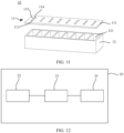
- an embodiment of this application further provides a power system 20.
- the power system20 may include an inverter 21, a power device 22, and any one of the foregoing batteries 10.
- the power device 22 may be connected to the battery 10 by using the inverter 21.
- a type of the electric energy in the battery 10 is generally a direct current, and a power consumption type of the power device 22 may be an alternating current.
- the inverter 21 may be configured to implement conversion between the alternating current and the direct current.
- the power device 22 may be a wind power generation device, a solar power generation device, or the like.
- the power system 20 may be a wind power system or a solar power system
- the power device 22 may alternatively be an electric device such as a motor.
- a specific type of the power device 22 is not limited in this application.
- the battery 10 may be applied to a terminal such as a mobile phone, a vehicle, a ship, an unmanned aerial vehicle, or a base station, and is also used for power station energy storage, home energy storage, or the like.
- a terminal such as a mobile phone, a vehicle, a ship, an unmanned aerial vehicle, or a base station
- An application scenario of the battery 10 is not limited in this application.
- the battery management system 04 may be disposed at a terminal, or may be disposed at a remote end.
- the battery management system 04 may be installed on the vehicle.
- the battery management unit 02 may be disposed at a location such as the base station. In other words, when the battery management unit 02 is connected to the battery management system 04 in a wireless communication manner, a layout position of the battery management system 04 may be adjusted according to an actual situation, thereby achieving relatively high flexibility.
Landscapes
- Chemical & Material Sciences (AREA)
- Chemical Kinetics & Catalysis (AREA)
- Electrochemistry (AREA)
- General Chemical & Material Sciences (AREA)
- Engineering & Computer Science (AREA)
- Manufacturing & Machinery (AREA)
- Microelectronics & Electronic Packaging (AREA)
- Secondary Cells (AREA)
- Battery Mounting, Suspending (AREA)
Abstract
Description
- This application relates to the field of battery technologies, and in particular, to a battery cover plate, a battery, and a power system
- With the continuous popularization and development of clean energy, batteries are widely used in scenarios such as data centers, base stations, mobile phones, and vehicles. Moreover, the batteries are required to have higheruse safety and better intelligence.
- In practical application of the battery, a health status of the battery needs to be effectively monitored, to ensure use safety and service life of the battery. The battery mainly includes a housing and a bare cell located inside the housing. To monitor the health status of the battery, the current battery may further include a battery management unit (battery management unit, BMU) and a sensor assembly. The battery management unit is usually disposed outside the housing, and the sensor assembly needs to be disposed inside the housing to effectively detect parameters such as a temperature, pressure, and gas composition inside the housing. Currently, the housing is usually made of a metal material such as aluminum alloy. Therefore, the housing has electromagnetic shielding performance. The battery management unit and the sensor assembly need to be connected through a cable, and the cable needs to pass through the housing. Therefore, there are problems such as complex sealing and difficulty in ensuring sealing between the cable and the housing, so that safety of the battery cannot be effectively ensured. In addition, a manufacturing process is also complex.
- This application provides a battery cover plate, a battery, and a power system that are easy to manufacture and capable of effectively ensuring sealing and use safety of the battery.
- According to an aspect, this application provides a battery cover plate, including a plate body, a battery management unit, and a sensor assembly. The plate body is provided with an outer surface and an inner surface facing away from the outer surface. The battery management unit is disposed in the plate body, where a transmission structure is provided between the battery management unit and the outer surface, the battery management unit includes a wireless communication module, and the wireless communication module is capable of performing wireless communication with the outside by using the transmission structure. The sensor assembly is connected to the battery management unit, where the sensor assembly is disposed in the plate body and extends out of the inner surface.
- It should be noted that, in specific application, the battery may include the battery cover plate, the housing, and the bare cell. The housing may have a groove, and the bare cell may be disposed in the groove. The inner surface of the battery cover plate faces the groove and seals an opening of the groove. In other words, the battery cover plate and the housing may form a closed groove, so as to ensure sealing of the bare cell. The sensor assembly may be configured to detect parameters such as temperature of the groove (or the bare cell), barometric pressure in the groove, and gas composition. The sensor assembly is connected to the battery management unit, so that detected information of the sensor assembly can be transmitted to the battery management unit. The battery management unit may be connected to a positive tab and a negative tab of the bare cell, and is configured to detect parameters such as a status of charges, a health status, and a power status of the bare cell. Because the plate body has the transmission structure for electromagnetic wave penetration, the battery management unit may transmit, to an external battery management system or the like by using the wireless communication module, the detected information obtained by the sensor assembly. Alternatively, it may be understood that, in the battery cover plate provided in this application, the transmission structure for electromagnetic wave propagation is disposed, so that the battery management unit disposed in the plate body of the battery cover plate can be communicatively connected to the battery management system in a wireless communication manner, thereby avoiding arrangement of the cable, and effectively ensuring the sealing of the battery cover plate. In addition, in a wireless communication manner, flexibility of the battery during deployment can be improved, constraint of the cable is avoided, and maintenance difficulty can also be reduced.
- In an example, the battery cover plate may include an insulator, and the battery management unit may be located in the insulator. The battery management unit is disposed in the insulator, which can not only protect the battery management unit well, prevent the battery management unit from being corroded by external impurities such as dust or water vapor, but also increase connection strength between the battery management unit and the plate body, and effectively prevent an adverse situation such as shaking or disengagement between the battery management unit and the plate body.
- In specific arrangement, the insulator may be disposed in various positions in the plate body.
- For example, the insulator may be located between the outer surface and the inner surface. To enable the battery management unit in the insulator to communicate with the outside in wireless mode, an end of the transmission structure may extend to the insulator.
- The transmission structure may be a structure such as a gap or a blind via. A specific shape of the transmission structure is not limited in this application. In addition, the transmission structure may be further filled with an insulating material, so as to improve flatness of the inner surface.
- Alternatively, in an example, the insulator and the insulating material filled in the transmission structure may be an integrally formed structure, so as to improve convenience in manufacturing.
- Alternatively, in an example, an end of the insulator may extend to the inner surface, the sensor assembly may be disposed on the insulator, and a part (for example, a detection head) used for detection in the sensor assembly may extend out of an end surface of a second end. During manufacturing, the battery management unit and the sensor assembly may be plastic-packaged in the insulator, so as to simplify a manufacturing process.
- In addition, in specific application, the plate body may be made of a metal material such as aluminum or aluminum alloy. The insulator is prepared by injection molding or compression molding. Alternatively, an entire plate body may be made of an insulating material, and the insulator may be a part of an area of the plate body.
- In specific application, the sensor assembly may include a temperature sensor, a barometric pressure sensor, a gas sensor, or the like. The temperature sensor may be configured to detect temperature of the bare cell (or in the groove). The barometric pressure sensor may be configured to detect barometric pressure in the groove. The gas sensor may be configured to detect gas composition in the groove, or may detect a proportion of the gas composition, or the like. In addition, the sensor assembly may be disposed in the insulator, or may be disposed on the inner surface of the plate body. Alternatively, some sensors in the sensor assembly may be disposed in the insulator, and other sensors may be disposed on the inner surface of the plate body. A quantity and types of sensors included in the sensor assembly are not limited in this application.
- In an example, the battery cover plate may further include a positive-electrode pole and a negative-electrode pole. The positive-electrode pole and the negative-electrode pole may be disposed on the plate body, and the battery management unit is connected to the positive-electrode pole and negative-electrode pole.
- In specific application, the positive-electrode pole may be connected to a positive tab of the bare cell, and the negative-electrode pole may be connected to a negative tab of the bare cell. The positive-electrode pole and the negative-electrode pole may extend out of the outer surface, so as to be connected to another electric device or power supply device.
- In addition, the battery management unit may be connected to the positive-electrode pole and negative-electrode pole. Therefore, the battery management unit may be powered by the bare cell, to avoid that an additional power supply is disposed to supply power to the battery management unit.
- In an example, the battery management system may further include a power supply control circuit, and the sensor assembly may be connected to the battery management system by using the power supply control circuit. Alternatively, electric energy may supply power to the sensor assembly by using the power supply control circuit. The battery management system may connect or disconnect power supply to/fromthe sensor assembly by using the power supply control circuit, so as to achieve an effect of energy conservation.
- In an example, the battery cover plate may further include an explosion-proof structure, and the explosion-proof structure may be disposed on the plate body. The explosion-proof structure may be a structure such as an explosion-proof valve or an explosion-proof film When pressure in the groove is excessively large, pressure relief may be performed by using the explosion-proof structure, so as to prevent an adverse situation such as battery explosion. According to another aspect, this application further provides a battery, which may include a housing and a bare cell. The housing has a groove, and the bare cell may be disposed in the groove. The battery may further include any one of the foregoing battery cover plates. The battery cover plate may cover an opening of the groove, with the inner surface disposed facing the groove, and the sensor assembly extends into the groove.
- In specific application, the housing may have one groove, or may have a plurality of grooves. When the housing has a plurality of grooves, the battery cover plate may cover the opening of each groove at the same time. A quantity of disposed sensor assemblies in the battery cover plate may be the same as a quantity of disposed grooves, and the sensor assemblies are disposed in one-to-one correspondence with the grooves.
- In addition, when the battery management unit is disposed, a quantity of disposed battery management units may be the same as a quantity of disposed sensor assemblies, or a quantity of disposed battery management units may be less than a quantity of disposed sensor assemblies.
- In addition, in an example, the battery may further include a battery management system, and the battery management unit is connected to the battery management system in a wireless communication manner. In specific application, the battery management unit may send detected information to the battery management system, and the battery management system may separately manage each battery management unit according to the detected information, so as to implement refined management.
- According to another aspect, this application further provides a power system, which may include any one of the foregoing batteries. The inverter may be connected to a battery, and may be configured to convert an alternating current into a direct current and then provide the direct current to the battery, or convert a direct current from the battery into an alternating current. In specific application, the power system may be an energy storage system, or may be a solar or wind power system A specific type of the power system is not limited in this application.
-
-
FIG. 1 is a schematic diagram of a cross-sectional structure of a conventional battery according to an embodiment of this application; -
FIG. 2 is a schematic diagram of a cross-sectional structure of another conventional battery according to an embodiment of this application; -
FIG. 3 is a schematic diagram of a cross-sectional structure of a battery according to an embodiment of this application; -
FIG. 4 is a schematic diagram of a cross-sectional structure of another battery coverplate according to an embodiment of this application; -
FIG. 5 is a top view ofFIG. 4 ; -
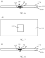
FIG. 6 is a schematic diagram of a cross-sectional structure of another battery coverplate according to an embodiment of this application; -
FIG. 7 is a top view ofFIG. 6 ; -
FIG. 8 is a schematic diagram of a cross-sectional structure of another battery coverplate according to an embodiment of this application; -
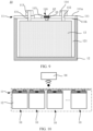
FIG. 9 is a schematic diagram of a cross-sectional structure of a battery according to an embodiment of this application; -
FIG. 10 is a schematic diagram of a structure of a battery group according to an embodiment of this application; -
FIG. 11 is a schematic exploded diagram of a structure of another battery according to an embodiment of this application; and -
FIG. 12 is a block diagram of a structure of a power system according to an embodiment of this application. - To make objectives, technical solutions, and advantages of this application clearer, the following further describes this application in detail with reference to the accompanying drawings.
- To facilitate understanding of the battery cover plate provided in embodiments of this application, an application scenario thereof is first described below.
-
FIG. 1 shows aconventional battery 01 according to an embodiment of this application. Thebattery 01 mainly includes ahousing 011, abare cell 012, and abattery cover plate 013. Specifically, thehousing 011 has agroove 0111, thebare cell 012 is disposed in thegroove 0111, and thebattery cover plate 013 covers an opening of thegroove 0111 to ensure sealing of thegroove 0111. During actual application, a medium such as an electrolyte is usually disposed in thegroove 0111, to ensure a normal charging/discharging function of thebare cell 012. In addition, in a process of using thebattery 01, a case such as excessive charge/discharge, a pressure change, a temperature change, or a gas composition change may occur in the bare cell 012 (or in the groove 0111). Therefore, to ensure use safety of thebattery 01, electricity, a temperature, and gas composition inside the battery 01 (or the bare cell) need to be effectively monitored. - Details are shown in
FIG. 2 . Currently, to implement intelligent management and control on thebattery 01, a battery management unit 02 (battery management unit), asensor assembly 03, and a battery management system 04 (battery management system) are usually configured. Thebattery management unit 02 and thesensor assembly 03 may be fastened to thebattery cover plate 013. Specifically, thesensor assembly 03 may extend into thegroove 0111, and is configured to effectively detect the temperature, pressure, and gas composition in thegroove 0111, and send detected data to thebattery management unit 02. Thebattery management unit 02 may send the detected data to thebattery management system 04. In addition, thebattery management unit 02 may be connected to apositive tab 0121 and anegative tab 0122 of thebare cell 012, and is configured to detect parameters such as a state of charge (state of charge, SOC), a health status, and a power status of thebare cell 012. Thebattery management system 04 may adjust temperature of thebattery 01 based on the detected data of thesensor assembly 03 and thebattery management unit 02, or thebattery management system 04 may regulate and control a charging/discharging state of thebattery 01 by using thebattery management unit 02, or the like. Currently, thebattery cover plate 013 is generally made of a metal material such as aluminum or aluminum alloy, and has electromagnetic shielding performance. If thebattery management unit 02 is disposed inside thebattery cover plate 013, thebattery management unit 02 needs to be connected to thebattery management system 04 through a cable 05. In addition, a through hole (not shown in the figure) for the cable 05 to pass through needs to be disposed in thebattery cover plate 013. However, a disposed through hole may damage sealing performance of thebattery 01, and increase a safety hazard of thebattery 01. If sealing processing is performed between the cable 05 and thebattery cover plate 013, problems such as a complex process and low reliability exist. - Therefore, an embodiment of this application provides a battery cover plate that has a simple structure, is easy to implement, and can effectively improve battery safety.
- To make objectives, technical solutions, and advantages of this application clearer, the following further describes this application in detail with reference to the accompanying drawings and specific embodiments.
- Terms used in the following embodiments are merely intended to describe specific embodiments, but are not intended to limit this application. As used in the specification of this application and the appended claims, singular expression forms "one", "a", and "this" are intended to also include an expression form such as "one or more", unless otherwise specified in the context. It should be further understood that, in the following embodiments of this application, "at least one" means one, two, or more.
- Reference to "an embodiment" described in this specification or the like means that one or more embodiments of this application include a particular feature, structure, or characteristic described with reference to the embodiment. Therefore, in this specification, statements, such as "in an embodiment", "in some embodiments", and "in other embodiments", that appear at different places do not necessarily mean referring to a same embodiment, instead, the statements mean referring to "one or more but not all of the embodiments", unless otherwise specifically emphasized in other ways. The terms "include", "have", and variants thereof all mean "including but not limited to", unless otherwise specifically emphasized in another manner.
- As shown in
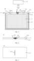
FIG. 3 , in an embodiment provided in this application, abattery 10 may include abattery cover plate 11, ahousing 12, and abare cell 13. Thehousing 12 has agroove 121, thebare cell 13 is disposed in thegroove 121, and thebattery cover plate 11 covers an opening of thegroove 121. In other words, thebattery cover plate 11 and thehousing 12 may form a closed structure, so as to ensure sealing of thebare cell 13. Thebattery cover plate 11 may include aplate body 111, abattery management unit 02, and asensor assembly 03. Specifically, theplate body 111 is provided with anouter surface 111a (for example, an upper plate surface in the figure) and aninner surface 111b (for example, a lower plate surface in the figure) facing away from theouter surface 111a, and theouter surface 111a has atransmission structure 110 for electromagnetic wave propagation. Thebattery management unit 02 is disposed in theplate body 111, thebattery management unit 02 includes a wireless communication module, and the wireless communication module may perform wireless communication with the outside by using thetransmission structure 110. Thesensor assembly 03 extends out of theinner surface 111b, and is connected to thebattery management unit 02. Specifically, thesensor assembly 03 may be configured to detect parameters such as temperature of the groove 121 (or the bare cell 13), barometric pressure in thegroove 121, and gas composition. Thesensor assembly 03 is connected to thebattery management unit 02, so that detected information of thesensor assembly 03 can be transmitted to thebattery management unit 02. Thebattery management unit 02 may be connected to apositive tab 131 and anegative tab 132 of thebare cell 13, and is configured to detect parameters such as a state of charge, a health status, and a power status of thebare cell 13. Because theplate body 111 has thetransmission structure 110 for electromagnetic wave penetration, thebattery management unit 02 may transmit, to an externalbattery management system 04 or the like by using the wireless communication module, the detected information obtained by thesensor assembly 03. Alternatively, it may be understood that, in thebattery cover plate 11 provided in this application, thetransmission structure 110 for electromagnetic wave propagation is disposed, so that thebattery management unit 02 disposed in theplate body 111 of thebattery cover plate 11 can be communicatively connected to thebattery management system 04 in a wireless communication manner, thereby avoiding arrangement of the cable, and effectively ensuring sealing of thebattery cover plate 11. In addition, in a wireless communication manner, flexibility of thebattery 10 during deployment can be improved, constraint of the cable is avoided, and maintenance difficulty can also be reduced. - It should be noted that the
bare cell 13 is an electrochemical cell including a positive electrode and a negative electrode, and a specific chemical composition and a type of thebare cell 13 are not limited in this application. Alternatively, thebattery 10 may be a lithium battery, a lead-acid battery, a lithium-sulfur battery, a sodium battery, a magnesium battery, an aluminum battery, a potassium battery, or the like. In addition, the wireless communication module may be a device that meets a wireless technical standard such as Bluetooth or Wi-Fi. A specific type, an operating frequency band, and a technical standard of the wireless communication module are not limited in this application. - In specific application, the
plate body 111 may be made of a metal material such as aluminum, aluminum alloy, or steel, so that theplate body 111 has good structural strength. Certainly, theplate body 111 made of a metal material generally has an electromagnetic shielding function. Therefore, in an embodiment provided in this application, after thetransmission structure 110 is disposed, thebattery management unit 02 located inside theplate body 111 can communicate with the externalbattery management system 04 in a wireless communication manner. It may be understood that, in other embodiments, theplate body 111 may also be made of at least one material of polymers, such as polypropylene, polyvinylidene fluoride, polyethylene, polymethyl methacrylate, and polyvinyl acetate, and a copolymer thereof. Alternatively, it may be understood that theplate body 111 may be made of an insulating material, so that anentire plate body 111 does not have the electromagnetic shielding function. Therefore, thebattery management unit 02 disposed inside theplate body 111 can communicate with the outside in a wireless communication manner. - It should be noted that, when the
plate body 111 is made of a material that does not have an electromagnetic shielding effect or has a relatively weak electromagnetic shielding effect, such as the insulating material, thetransmission structure 110 may be a partial area of theplate body 111 between theouter surface 111a and thebattery management unit 02, or thetransmission structure 110 may alternatively be a structure having an entity shape such as a gap or a blind via extending from theouter surface 111a to thebattery management unit 02. - For ease of understanding technical solutions of this application, the following uses an example in which the
plate body 111 is made of the material having the electromagnetic shielding effect such as metal for description. - In specific application, the
battery management unit 02 may be disposed in various manners. - For example, as shown in
FIG. 4 , in another example provided in this application, thebattery cover plate 11 may further include aninsulator 112, and thebattery management unit 02 may be located in theinsulator 112. During manufacturing, an accommodating cavity (not shown in the figure) configured to accommodate theinsulator 112 may be disposed in theplate body 111. Then, thebattery management unit 02 is placed in the accommodating cavity, and finally the insulating material is injected into the accommodating cavity. After the insulating material is cured and formed, theinsulator 112 may be formed. Alternatively, thebattery management unit 02 may be plastic-packaged in theinsulator 112 by using an injection molding process, and then theinsulator 112 having thebattery management unit 02 is fastened in the accommodating cavity. - The
insulator 112 may be made of an insulating material such as a polymer such as polypropylene, polyvinylidene fluoride, polyethylene, polymethyl methacrylate, and polyvinyl acetate, and a copolymer thereof, so that electromagnetic waves can propagate through theinsulator 112. Thebattery management unit 02 is disposed in theinsulator 112, which can not only protect thebattery management unit 02 well, prevent thebattery management unit 02 from being corroded by external impurities such as dust or water vapor, but also increase connection strength between thebattery management unit 02 and theplate body 111, and effectively prevent an adverse situation such as shaking or disengagement between thebattery management unit 02 and theplate body 111. - During specific implementation, the
insulator 112 may be located in various positions in theplate body 111. - For example, as shown in
FIG. 4 , this application provides an example. Theinsulator 112 is located inside theplate body 111, meaning that theinsulator 112 does not extend to theouter surface 111a or theinner surface 111b. - In addition, to enable the
battery management unit 02 to perform wireless communication with the outside, an end of thetransmission structure 110 may extend to theinsulator 112. It should be known that the end of thetransmission structure 110 is a part of thetransmission structure 110 that faces the insulator. Specifically, the part that faces the insulator may be a regular or irregular surface. It should be noted that the end of thetransmission structure 110 does not mean that thetransmission structure 110 is narrow and long in a thickness direction of theinsulator 112. - For example, refer to
FIG. 4 and FIG. 5 . In an example provided in this application, thetransmission structure 110 is specifically a gap, the gap has a specific depth, and a bottom end of the gap extends to an upper surface of theinsulator 112. The upper surface of theinsulator 112 is a surface of theinsulator 112 that faces and is close to theouter surface 111a. An electromagnetic wave generated by the wireless communication module in thebattery management unit 02 can be propagated to the outside through the gap. Alternatively, an external electromagnetic wave can be propagated to the wireless communication module in thebattery management unit 02 through the gap. - Certainly, in another implementation, the
transmission structure 110 may alternatively be a structure such as a blind via. In addition, there may be one, two, ormore transmission structures 110. A specific shape and quantity of thetransmission structures 110 are not limited in this application. - Alternatively, as shown in
FIG. 6 and FIG. 7 , in another example provided in this application, thetransmission structure 110 may be further filled with an insulating material, to ensure flatness of theouter surface 111a. The insulating material filled in thetransmission structure 110 may be the same as or different from the material of theinsulator 112. In addition, when theinsulator 112 is filled in the accommodating cavity, the insulating material may also be filled in thetransmission structure 110 at the same time. Theinsulator 112 and the insulating material filled in thetransmission structure 110 may be an integrally formed structure, so as to simplify a manufacturing process. - In addition, as shown in
FIG. 8 , in another example provided in this application, a second end (a lower end in the figure) of theinsulator 112 may extend to theinner surface 111b, and theinsulator 112 does not extend to theouter surface 111a. An anti-theft effect of thebattery management unit 02 can be improved by using this structure. - For details, refer to
FIG. 8 andFIG. 9 . When thebattery cover plate 11 covers the opening of thegroove 121, theouter surface 111a may be a flat surface. Therefore, a position of theinsulator 112 or a position of thebattery management unit 02 is hidden. In addition, theplate body 111 and thehousing 12 may be fixedly connected by using a screw, or a rivet, or by welding, so as to effectively improve an anti-theft effect of thebattery management unit 02. - In addition, when the
battery management unit 02 is injected into theinsulator 112, injection molding may be performed on thesensor assembly 03 at the same time. Specifically, thebattery management unit 02 and thesensor assembly 03 may be first connected, to implement a communication connection or a power supply connection between thebattery management unit 02 and thesensor assembly 03. Thebattery management unit 02 is connected to thesensor assembly 03 by using a connection structure such as a microstrip or a conductive wire. Alternatively, thebattery management unit 02 and thesensor assembly 03 may be disposed on a same circuit board. Then, thebattery management unit 02 and thesensor assembly 03 are processed by using a process such as injection molding or compression molding, to prepare theinsulator 112, and then thebattery management unit 02 is injected into theinsulator 112, and a part of thesensor assembly 03 is injected into theinsulator 112. It should be noted that, when the injection molding is performed on thesensor assembly 03, a part (for example, a detection head) used for detection in thesensor assembly 03 extends out of theinsulator 112, so as to prevent theinsulator 112 from hindering detection performed by thesensor assembly 03. - In the example provided in this application, the
battery management unit 02 and the part of thesensor assembly 03 may be injected into theinsulator 112, so that thebattery management unit 02, thesensor assembly 03, and theinsulator 112 can be fastened. In addition, theinsulator 112 can further effectively protect thebattery management unit 02, thesensor assembly 03, and the connection structure between thebattery management unit 02 and the sensor, thereby effectively improving security. In addition, it is also convenient to manufacture thebattery management unit 02 and thesensor assembly 03 as an integrated structure by using theinsulator 112, so that thebattery management unit 02 and thesensor assembly 03 can be efficiently and accurately applied to theplate body 111, thereby improving manufacturing convenience and an application scope. - Certainly, in another implementation, a first end of the
insulator 112 may extend to theouter surface 111a, and the second end may extend to theinner surface 111b, so that manufacturing efficiency can be effectively improved, and a manufacturing process can be simplified. - It should be noted that, in specific application, the
sensor assembly 03 may include a temperature sensor, a barometric pressure sensor, a gas sensor, or the like. The temperature sensor may be configured to detect the temperature of the bare cell 13 (or in the groove 121). The barometric pressure sensor may be configured to detect barometric pressure in thegroove 121. The gas sensor may be configured to detect gas composition in thegroove 121, or may detect a proportion of the gas composition, or the like. In addition, thesensor assembly 03 may be disposed in theinsulator 112, or may be disposed on theinner surface 111b of theplate body 111. Alternatively, some sensors in thesensor assembly 03 may be disposed in theinsulator 112, and other sensors may be disposed on theinner surface 111b of theplate body 111. - Alternatively, in another implementation, the
insulator 112 may be omitted. For example, thebattery management unit 02 may also be fastened in the accommodating cavity by screwing, welding, bonding, or the like. When thebattery cover plate 11 is impacted by vibration or external force, thebattery management unit 02 can still be stably located in the accommodating cavity, so that thebattery cover plate 11 has good structural safety. When theinsulator 112 is not disposed, the accommodating cavity in theplate body 111 may be disposed in a position similar to a position of theinsulator 112 in the foregoing example, and details are not described herein again. - During actual application, a molding mode and preparation process of the
battery management unit 02, theinsulator 112, and theplate body 111 can be flexibly adjusted, which is not limited in this application. - In addition, it should be noted that when the
plate body 111 is made of an insulating material, theinsulator 112 may be omitted. Thebattery management unit 02 may be disposed inside theplate body 111 by using a process such as injection molding or compression molding. Alternatively, at least a part of theplate body 111 may form theinsulator 112. - In addition, as shown in
FIG. 9 , in an embodiment provided in this application, thebattery cover plate 11 may further include a positive-electrode pole 113 and a negative-electrode pole 114. The positive-electrode pole 113 may be connected to apositive tab 131 of thebare cell 13, and the negative-electrode pole 114 may be connected to anegative tab 132 of thebare cell 13. Alternatively, it may be understood that electric energy of thebare cell 13 may be transmitted to an external electric device through the positive-electrode pole 113 and the negative-electrode pole 114. Alternatively, an external power supply device may supplement the electric energy to thebare cell 13 through the positive-electrode pole 113 and the negative-electrode pole 114. - In specific application, the positive-
electrode pole 113 and the negative-electrode pole 114 may have various structures and shapes. - For example, the positive-
electrode pole 113 and the negative-electrode pole 114 may be cylindrical structures. Alternatively, the positive-electrode pole 113 and the negative-electrode pole 114 may be conductive sheets or of other shapes and structures. Specific shapes of the positive-electrode pole 113 and the negative-electrode pole 114 are not limited in this application. - In addition, the positive-
electrode pole 113 and thepositive tab 131 may be connected by welding, abutting, or screwing. Correspondingly, the negative-electrode pole 114 and thenegative tab 132 may be connected by welding, abutting, or screwing. A manner of connecting the positive-electrode pole 113 to thepositive tab 131 and a manner of connecting the negative-electrode pole 114 to thenegative tab 132 are not limited in this application. - In addition, in specific application, the
battery management unit 02 may be connected to the positive-electrode pole 113 and the negative-electrode pole 114. When the positive-electrode pole 113 is connected to thepositive tab 131 and the negative-electrode pole 114 is connected to thenegative tab 132, thebare cell 13 can supply power to thebattery management unit 02, to avoid that an additional power supply or a power supply device is disposed to supply power to thebattery management unit 02. - Certainly, in other implementations, the
battery management unit 02 may not be connected to the positive-electrode pole 113 or the negative-electrode pole 114. Thebattery cover plate 11 may be provided with a conductive contact connected to thebattery management unit 02. After thebattery cover plate 11 covers thegroove 121, the conductive contact may be connected to thepositive tab 131 and thenegative tab 132, so that thebare cell 13 can supply power to thebattery management unit 02. - In addition, in some implementations, the positive-
electrode pole 113 and thepositive tab 131 may be connected by using a fuse circuit (not shown in the figure). Specifically, thebattery management unit 02 may be connected to the fuse circuit, and is configured to control a connected or disconnected state between the positive-electrode pole 113 and thepositive tab 131. When communication connection is maintained between thebattery management unit 02 and thebattery management system 04, thebattery management unit 02 may enable the positive-electrode pole 113 and thepositive tab 131 to be in a connected state through the fuse circuit. When communication between thebattery management unit 02 and thebattery management system 04 is disconnected, thebattery management unit 02 may disconnect the positive-electrode pole 113 from thepositive tab 131 through the fuse circuit, so as to prevent thebattery 10 from being used after thebattery 10 is stolen. A condition for determining whether the communication connection is maintained between thebattery management unit 02 and thebattery management system 04 may be set according to an actual requirement. For example, it is assumed that the communication connection between thebattery management unit 02 and thebattery management system 04 is continuous and uninterrupted. In this case, if thebattery management unit 02 does not communicate with thebattery management system 04 within a time period greater than a preset time period (for example, 2 seconds), it indicates that the communication between thebattery management unit 02 and thebattery management system 04 is disconnected. - Alternatively, it is assumed that the communication connection between the
battery management unit 02 and thebattery management system 04 is periodic (for example, communication is performed every 5 seconds). In a preset time period (for example, 10 seconds), if at least one communication connection between thebattery management unit 02 and thebattery management system 04 exists, it may be determined that the communication connection between thebattery management unit 02 and thebattery management system 04 is maintained. If there is no communication connection between thebattery management unit 02 and thebattery management system 04 within 10 seconds, it indicates that the communication between thebattery management unit 02 and thebattery management system 04 is disconnected. - Certainly, during actual application, a condition for determining whether the
battery management unit 02 is communicatively connected to thebattery management system 04 may be properly set based on an actual situation. This is not limited in this application. - The fuse circuit may include a circuit switch, meaning that a connected or disconnected state between the positive-
electrode pole 113 and thepositive tab 131 may be switched for a plurality of times by using the fuse circuit. Alternatively, the fuse circuit may include a fuse, meaning that the fuse circuit may be one-off. After the fuse circuit disconnects the positive-electrode pole 113 from the positive tab 131 (that is, after the fuse is fused), the fuse circuit cannot be recovered. It may be understood that a specific type of the fuse circuit is not limited in this application. - In addition, the negative-
electrode pole 114 may also be connected to thenegative tab 132 through the fuse circuit, and details are not described herein. - It may be understood that the
sensor assembly 03 also needs electric energy when working normally. Thesensor assembly 03 is connected to thebattery management unit 02, and electric energy of thebare cell 13 may be transmitted to thesensor assembly 03 through thebattery management unit 02. - In some implementations, the
battery management unit 02 may include a power supply control circuit (not shown in the figure), and the power supply control circuit may be configured to connect or disconnect power supply to/from thesensor assembly 03. For example, in specific application, the electric energy may be continuously transmitted to thesensor assembly 03, so that thesensor assembly 03 can continuously detect a related parameter. Alternatively, through the power supply control circuit, the electric energy may be intermittently transmitted to thesensor assembly 03, so that the electric energy can be effectively resolved, and a normal detection function of thesensor assembly 03 can be ensured. - In addition, in an example provided in this application, the
battery cover plate 11 may further include an explosion-proof structure 115. The explosion-proof structure 115 is disposed on theplate body 111. Specifically, the explosion-proof structure 115 passes through theouter surface 111a and theinner surface 111b of theplate body 111. When barometric pressure in thegroove 121 is excessively high, the explosion-proof structure 115 may implement pressure relief, to prevent an adverse situation such as explosion of thebattery 10. - In specific arrangement, the explosion-
proof structure 115 may be a well-known conventional structure such as an explosion-proof film or an explosion-proof valve, and details are not described herein. - It may be understood that in the foregoing example, one
battery 10 is used as an example for description. During actual application, a plurality ofbatteries 10 may be disposed in a group. - For example, as shown in
FIG. 10 , in an example provided in this application, the plurality ofbatteries 10 may be included. Eachbattery 10 includes ahousing 12, a bare cell (not shown in the figure), and abattery cover plate 11. The plurality ofbatteries 10 may be disposed in series or in parallel to meet a required power supply requirement. Alternatively, it may be understood that eachbattery 10 is independent of each other. During actual application, a quantity of requiredbatteries 10 and a position in which thebattery 10 is disposed may be flexibly adjusted according to an actual requirement, so that thebattery 10 has relatively good adaptability. - Alternatively, as shown in
FIG. 11 , in another example provided in this application, thehousing 12 has a plurality of grooves 121 (eight grooves are shown in the figure), and the plurality ofgrooves 121 face a same direction. Media such as a bare cell (not shown in the figure) and an electrolyte may be disposed in eachgroove 121, and multiple bare cells may be connected in series or in parallel. In addition, thebattery cover plate 11 may simultaneously covermultiple grooves 121, thereby effectively reducing assembly difficulty and reducing convenience during manufacturing. When thebattery cover plate 11 is disposed, thebattery cover plate 11 may include a plurality of battery management units (not shown in the figure), a sensor assembly (not shown in the figure), and an explosion-proof structure 115. Specifically, a quantity of disposed grooves 121 (or bare cells) may be the same as a quantity of disposed battery management units, sensor assemblies, and explosion-proof structures 115. In other words, the battery management unit, the sensor assembly, and the explosion-proof structure 115 in thebattery cover plate 11 are disposed in one-to-one correspondence with the groove 121 (or the bare cell), so that each groove 121 (or the bare cell) is equipped with an independent battery management unit, a sensor assembly, and an explosion-proof structure 115, so that independent detection, control, or pressure relief is performed on each bare cell, thereby facilitating refined management. - Certainly, in specific application, the quantity of disposed battery management units may also be less than the quantity of disposed sensor assemblies or
grooves 121. - For example, only one battery management unit may be provided in the
battery cover plate 11, and the battery management unit may be connected to each sensor assembly and the bare cell, so that the quantity of disposed battery management units can be effectively reduced, thereby helping reduce manufacturing costs of thebattery cover plate 11. - It may be understood that the quantity of disposed battery management units is not limited in this application. During actual application, the
battery 10 provided in the embodiment of this application may be applied to a plurality of different application scenarios. - For example, as shown in
FIG. 12 , an embodiment of this application further provides apower system 20. The power system20 may include aninverter 21, apower device 22, and any one of the foregoingbatteries 10. Thepower device 22 may be connected to thebattery 10 by using theinverter 21. A type of the electric energy in thebattery 10 is generally a direct current, and a power consumption type of thepower device 22 may be an alternating current. Theinverter 21 may be configured to implement conversion between the alternating current and the direct current. - In specific application, the
power device 22 may be a wind power generation device, a solar power generation device, or the like. Alternatively, it may be understood that thepower system 20 may be a wind power system or a solar power system - In addition, in some implementations, the
power device 22 may alternatively be an electric device such as a motor. A specific type of thepower device 22 is not limited in this application. - Alternatively, the
battery 10 may be applied to a terminal such as a mobile phone, a vehicle, a ship, an unmanned aerial vehicle, or a base station, and is also used for power station energy storage, home energy storage, or the like. An application scenario of thebattery 10 is not limited in this application. - In addition, the
battery management system 04 may be disposed at a terminal, or may be disposed at a remote end. For example, when thebattery 10 is applied to a vehicle, thebattery management system 04 may be installed on the vehicle. Alternatively, thebattery management unit 02 may be disposed at a location such as the base station. In other words, when thebattery management unit 02 is connected to thebattery management system 04 in a wireless communication manner, a layout position of thebattery management system 04 may be adjusted according to an actual situation, thereby achieving relatively high flexibility. - The foregoing descriptions are merely specific implementations of this application, but are not intended to limit the protection scope of this application. Any variation or replacement readily figured out by a person skilled in the art within the technical scope disclosed in this application shall fall within the protection scope of this application. Therefore, the protection scope of this application shall be subject to the protection scope of the claims.
Claims (15)
- A battery cover plate, comprising:a plate body, provided with an outer surface and an inner surface facing away from the outer surface;a battery management unit, disposed in the plate body, wherein a transmission structure is provided between the battery management unit and the outer surface; andthe battery management unit comprises a wireless communication module, and the wireless communication module is capable of performing wireless communication with the outside by using the transmission structure; anda sensor assembly, connected to the battery management unit, wherein the sensor assembly is disposed in the plate body and extends out of the inner surface.
- The battery cover plate according to claim 1, wherein the plate body has an insulator, and the battery management unit is located in the insulator.
- The battery cover plate according to claim 2, wherein the insulator is located inside the plate body, and an end of the transmission structure extends to the insulator.
- The battery cover plate according to claim 3, wherein the transmission structure comprises a gap or a blind via.
- The battery cover plate according to claim 3 or 4, wherein the transmission structure is filled with an insulating material.
- The battery cover plate according to claim 5, wherein the insulator and the insulating material filled in the transmission structure are an integrally formed structure.
- The battery cover plate according to any one of claims 1 to 6, wherein an end of the insulator extends to the inner surface, and the sensor assembly is disposed on the insulator.
- The battery cover plate according to any one of claims 1 to 7, wherein the plate body is made of an insulating material.
- The battery cover plate according to any one of claims 1 to 8, wherein the battery coverplate further comprises a positive-electrode pole and a negative-electrode pole; and
the positive-electrode pole and the negative-electrode pole are disposed on the plate body, and the battery management unit is connected to the positive-electrode pole and the negative-electrode pole. - The battery cover plate according to any one of claims 1 to 10, wherein the battery management unit comprises a power supply control circuit, and the power supply control circuit is configured to connect or disconnect power supply to/from the sensor assembly.
- A battery, wherein the battery comprises a housing and a bare cell, the housing has a groove, and the bare cell is disposed in the groove; and
the battery further comprises the battery cover plate according to any one of claims 1 to 10, wherein the battery cover plate covers an opening of the groove, the inner surface faces the groove, and the sensor assembly extends into the groove. - The battery according to claim 11, wherein the battery management unit is electrically connected to the bare cell.
- The battery according to claim 11 or 12, wherein the housing has a plurality of grooves, a quantity of sensor assemblies is the same as that of grooves, and the sensor assemblies are disposed in one-to-one correspondence with the grooves.
- The battery according to any one of claims 11 to 13, wherein the battery further comprises a battery management system, and the battery management unit is connected to the battery management system in a wireless communication manner.
- A power system, comprising an inverter and the battery according to any one of claims 11 to 14, wherein the inverter is connected to the battery, and is configured to convert an alternating current into a direct current and then provide the direct current for the battery, or convert a direct current from the battery into an alternating current.
Applications Claiming Priority (1)
| Application Number | Priority Date | Filing Date | Title |
|---|---|---|---|
| CN202210194340.7A CN114678607B (en) | 2022-03-01 | 2022-03-01 | Battery cover plate, battery and power system |
Publications (2)
| Publication Number | Publication Date |
|---|---|
| EP4239756A1 true EP4239756A1 (en) | 2023-09-06 |
| EP4239756B1 EP4239756B1 (en) | 2025-12-03 |
Family
ID=82071561
Family Applications (1)
| Application Number | Title | Priority Date | Filing Date |
|---|---|---|---|
| EP23157904.6A Active EP4239756B1 (en) | 2022-03-01 | 2023-02-22 | Battery cover plate, battery, and power system |
Country Status (3)
| Country | Link |
|---|---|
| US (1) | US20230282914A1 (en) |
| EP (1) | EP4239756B1 (en) |
| CN (1) | CN114678607B (en) |
Cited By (1)
| Publication number | Priority date | Publication date | Assignee | Title |
|---|---|---|---|---|
| EP4618232A1 (en) * | 2024-03-15 | 2025-09-17 | BYD Company Limited | Cover plate assembly, battery, energy storage device, and power consuming device |
Families Citing this family (10)
| Publication number | Priority date | Publication date | Assignee | Title |
|---|---|---|---|---|
| EP4492534A4 (en) * | 2022-08-30 | 2025-11-26 | Contemporary Amperex Technology Hong Kong Ltd | BATTERY CELL, BATTERY AND ELECTRICAL DEVICE |
| WO2024044941A1 (en) * | 2022-08-30 | 2024-03-07 | 宁德时代新能源科技股份有限公司 | Battery cell, battery, and electric device |
| KR20240038398A (en) * | 2022-09-16 | 2024-03-25 | 주식회사 엘지에너지솔루션 | Wirelessly Connectable Cell Supervisory Circuit and Battery Module Using the Same |
| DE102022129456A1 (en) * | 2022-11-08 | 2024-05-08 | Man Truck & Bus Se | Cover for a cell contact system of an electrical energy storage device |
| CN118472440A (en) * | 2023-02-09 | 2024-08-09 | 宁德时代新能源科技股份有限公司 | End cover assembly, battery cell, battery and power utilization device |
| CN219917334U (en) * | 2023-07-10 | 2023-10-27 | 宁德时代新能源科技股份有限公司 | A battery cell, battery and electrical device |
| CN220439796U (en) * | 2023-07-25 | 2024-02-02 | 湖北亿纬动力有限公司 | Battery |
| EP4535500A1 (en) * | 2023-10-06 | 2025-04-09 | Belenos Clean Power Holding AG | Battery cell suitable for wireless communication of data signals, a battery comprising at least one cell |
| CN223023542U (en) * | 2024-02-29 | 2025-06-24 | 比亚迪股份有限公司 | Battery cell, battery pack and electricity utilization device |
| CN222581229U (en) * | 2024-03-15 | 2025-03-07 | 比亚迪股份有限公司 | Chip components for batteries, batteries, energy storage devices and electrical equipment |
Citations (9)
| Publication number | Priority date | Publication date | Assignee | Title |
|---|---|---|---|---|
| EP2600443A2 (en) * | 2011-11-16 | 2013-06-05 | Nxp B.V. | In-cell battery management device |
| WO2014023725A1 (en) * | 2012-08-09 | 2014-02-13 | Robert Bosch Gmbh | Housing for a battery cell with a housing cover having a monitoring electronics unit, battery cell, battery module and motor vehicle |
| CN204596917U (en) * | 2015-05-18 | 2015-08-26 | 山东圣阳电源股份有限公司 | A kind of intelligent battery lid |
| US20150301113A1 (en) * | 2010-09-10 | 2015-10-22 | Johnson Controls Technology Company | Vehicle battery monitoring system |
| DE102021100745A1 (en) | 2020-01-15 | 2021-07-15 | Denso Corporation | BATTERY MODULE AND ENERGY SYSTEM |
| US20210305681A1 (en) | 2020-03-30 | 2021-09-30 | Denso Corporation | Communication system |
| WO2021246633A1 (en) | 2020-06-02 | 2021-12-09 | 주식회사 엘지에너지솔루션 | Battery pack having optimization structure for wireless communication, and vehicle comprising same |
| EP3945657A1 (en) | 2020-07-31 | 2022-02-02 | Volvo Car Corporation | Intelligent battery cell with integrated monitoring and switches |
| US20220037703A1 (en) | 2020-07-31 | 2022-02-03 | Volvo Car Corporation | Integrated alternating current and direct current supply in a battery device |
Family Cites Families (3)
| Publication number | Priority date | Publication date | Assignee | Title |
|---|---|---|---|---|
| KR101736200B1 (en) * | 2016-02-03 | 2017-05-17 | 세방전지(주) | Battery pack |
| CN112290107A (en) * | 2020-09-14 | 2021-01-29 | 侯晓华 | Intelligent lithium ion battery packaging structure |
| CN214336836U (en) * | 2021-03-29 | 2021-10-01 | 蜂巢能源科技有限公司 | Electrical control box and battery pack |
-
2022
- 2022-03-01 CN CN202210194340.7A patent/CN114678607B/en active Active
-
2023
- 2023-02-22 EP EP23157904.6A patent/EP4239756B1/en active Active
- 2023-03-01 US US18/176,977 patent/US20230282914A1/en active Pending
Patent Citations (9)
| Publication number | Priority date | Publication date | Assignee | Title |
|---|---|---|---|---|
| US20150301113A1 (en) * | 2010-09-10 | 2015-10-22 | Johnson Controls Technology Company | Vehicle battery monitoring system |
| EP2600443A2 (en) * | 2011-11-16 | 2013-06-05 | Nxp B.V. | In-cell battery management device |
| WO2014023725A1 (en) * | 2012-08-09 | 2014-02-13 | Robert Bosch Gmbh | Housing for a battery cell with a housing cover having a monitoring electronics unit, battery cell, battery module and motor vehicle |
| CN204596917U (en) * | 2015-05-18 | 2015-08-26 | 山东圣阳电源股份有限公司 | A kind of intelligent battery lid |
| DE102021100745A1 (en) | 2020-01-15 | 2021-07-15 | Denso Corporation | BATTERY MODULE AND ENERGY SYSTEM |
| US20210305681A1 (en) | 2020-03-30 | 2021-09-30 | Denso Corporation | Communication system |
| WO2021246633A1 (en) | 2020-06-02 | 2021-12-09 | 주식회사 엘지에너지솔루션 | Battery pack having optimization structure for wireless communication, and vehicle comprising same |
| EP3945657A1 (en) | 2020-07-31 | 2022-02-02 | Volvo Car Corporation | Intelligent battery cell with integrated monitoring and switches |
| US20220037703A1 (en) | 2020-07-31 | 2022-02-03 | Volvo Car Corporation | Integrated alternating current and direct current supply in a battery device |
Cited By (1)
| Publication number | Priority date | Publication date | Assignee | Title |
|---|---|---|---|---|
| EP4618232A1 (en) * | 2024-03-15 | 2025-09-17 | BYD Company Limited | Cover plate assembly, battery, energy storage device, and power consuming device |
Also Published As
| Publication number | Publication date |
|---|---|
| CN114678607B (en) | 2025-11-07 |
| US20230282914A1 (en) | 2023-09-07 |
| CN114678607A (en) | 2022-06-28 |
| EP4239756B1 (en) | 2025-12-03 |
Similar Documents
| Publication | Publication Date | Title |
|---|---|---|
| EP4239756A1 (en) | Battery cover plate, battery, and power system | |
| CN216085200U (en) | Battery cell, battery and power consumption device | |
| US20230207992A1 (en) | Battery cell, method and system for manufacturing same, battery, and electrical device | |
| JP4154888B2 (en) | Battery module and vehicle equipped with battery module | |
| CN218919088U (en) | End cover assembly of battery unit, battery and electricity utilization device | |
| US20240421450A1 (en) | Battery cell, battery and electricity-consuming device | |
| CN218997009U (en) | Battery cells, batteries and electrical devices | |
| CN220628169U (en) | Cover components, secondary batteries and electronic equipment | |
| JP2023547006A (en) | Single battery, its manufacturing method and manufacturing system, battery and power usage equipment | |
| EP4415126A1 (en) | Battery, electronic device, and preparation method and preparation apparatus for battery | |
| CN222233692U (en) | Battery monomer, battery and power consumption device | |
| WO2025010825A1 (en) | Battery cell, battery and electrical device | |
| US20250038280A1 (en) | Battery cell, battery and electricity-consuming device | |
| CN203707194U (en) | Secondary battery | |
| US20240241178A1 (en) | Battery cell, battery, electricity-consuming apparatus, detecting method, and detecting module | |
| CN117410642B (en) | Explosion-proof battery of liquid filling port | |
| CN219658932U (en) | Battery monomer, battery and power consumption device | |
| WO2024036972A1 (en) | Battery and power system | |
| CN117199564A (en) | Battery management components, batteries and battery systems | |
| CN119404370A (en) | Battery cells, batteries and electrical devices | |
| CN223052236U (en) | Battery monomer, battery and power consumption device | |
| CN221994601U (en) | Battery unit and battery pack with same | |
| CN219350560U (en) | Protection plate of battery monomer, battery and power utilization device | |
| CN215933781U (en) | Mining battery and electronic equipment | |
| CN220492010U (en) | Top cap subassembly, battery and consumer |
Legal Events
| Date | Code | Title | Description |
|---|---|---|---|
| PUAI | Public reference made under article 153(3) epc to a published international application that has entered the european phase |
Free format text: ORIGINAL CODE: 0009012 |
|
| STAA | Information on the status of an ep patent application or granted ep patent |
Free format text: STATUS: REQUEST FOR EXAMINATION WAS MADE |
|
| 17P | Request for examination filed |
Effective date: 20230222 |
|
| AK | Designated contracting states |
Kind code of ref document: A1 Designated state(s): AL AT BE BG CH CY CZ DE DK EE ES FI FR GB GR HR HU IE IS IT LI LT LU LV MC ME MK MT NL NO PL PT RO RS SE SI SK SM TR |
|
| TPAC | Observations filed by third parties |
Free format text: ORIGINAL CODE: EPIDOSNTIPA |
|
| STAA | Information on the status of an ep patent application or granted ep patent |
Free format text: STATUS: EXAMINATION IS IN PROGRESS |
|
| 17Q | First examination report despatched |
Effective date: 20250211 |
|
| GRAP | Despatch of communication of intention to grant a patent |
Free format text: ORIGINAL CODE: EPIDOSNIGR1 |
|
| STAA | Information on the status of an ep patent application or granted ep patent |
Free format text: STATUS: GRANT OF PATENT IS INTENDED |
|
| INTG | Intention to grant announced |
Effective date: 20250716 |
|
| GRAS | Grant fee paid |
Free format text: ORIGINAL CODE: EPIDOSNIGR3 |
|
| GRAA | (expected) grant |
Free format text: ORIGINAL CODE: 0009210 |
|
| STAA | Information on the status of an ep patent application or granted ep patent |
Free format text: STATUS: THE PATENT HAS BEEN GRANTED |
|
| P01 | Opt-out of the competence of the unified patent court (upc) registered |
Free format text: CASE NUMBER: UPC_APP_8361_4239756/2025 Effective date: 20250930 |
|
| AK | Designated contracting states |
Kind code of ref document: B1 Designated state(s): AL AT BE BG CH CY CZ DE DK EE ES FI FR GB GR HR HU IE IS IT LI LT LU LV MC ME MK MT NL NO PL PT RO RS SE SI SK SM TR |
|
| REG | Reference to a national code |
Ref country code: CH Ref legal event code: F10 Free format text: ST27 STATUS EVENT CODE: U-0-0-F10-F00 (AS PROVIDED BY THE NATIONAL OFFICE) Effective date: 20251203 Ref country code: GB Ref legal event code: FG4D |
|
| REG | Reference to a national code |
Ref country code: DE Ref legal event code: R096 Ref document number: 602023009127 Country of ref document: DE |
|
| REG | Reference to a national code |
Ref country code: IE Ref legal event code: FG4D |
|
| REG | Reference to a national code |
Ref country code: NL Ref legal event code: MP Effective date: 20251203 |
|
| PG25 | Lapsed in a contracting state [announced via postgrant information from national office to epo] |
Ref country code: ES Free format text: LAPSE BECAUSE OF FAILURE TO SUBMIT A TRANSLATION OF THE DESCRIPTION OR TO PAY THE FEE WITHIN THE PRESCRIBED TIME-LIMIT Effective date: 20251203 |
|
| REG | Reference to a national code |
Ref country code: LT Ref legal event code: MG9D |
|
| PG25 | Lapsed in a contracting state [announced via postgrant information from national office to epo] |
Ref country code: NO Free format text: LAPSE BECAUSE OF FAILURE TO SUBMIT A TRANSLATION OF THE DESCRIPTION OR TO PAY THE FEE WITHIN THE PRESCRIBED TIME-LIMIT Effective date: 20260303 |
|
| PGFP | Annual fee paid to national office [announced via postgrant information from national office to epo] |
Ref country code: DE Payment date: 20251230 Year of fee payment: 4 |
|
| PG25 | Lapsed in a contracting state [announced via postgrant information from national office to epo] |
Ref country code: HR Free format text: LAPSE BECAUSE OF FAILURE TO SUBMIT A TRANSLATION OF THE DESCRIPTION OR TO PAY THE FEE WITHIN THE PRESCRIBED TIME-LIMIT Effective date: 20251203 Ref country code: FI Free format text: LAPSE BECAUSE OF FAILURE TO SUBMIT A TRANSLATION OF THE DESCRIPTION OR TO PAY THE FEE WITHIN THE PRESCRIBED TIME-LIMIT Effective date: 20251203 |
|
| PGFP | Annual fee paid to national office [announced via postgrant information from national office to epo] |
Ref country code: AT Payment date: 20260301 Year of fee payment: 4 |
|
| PG25 | Lapsed in a contracting state [announced via postgrant information from national office to epo] |
Ref country code: RS Free format text: LAPSE BECAUSE OF FAILURE TO SUBMIT A TRANSLATION OF THE DESCRIPTION OR TO PAY THE FEE WITHIN THE PRESCRIBED TIME-LIMIT Effective date: 20260303 |
|
| PG25 | Lapsed in a contracting state [announced via postgrant information from national office to epo] |
Ref country code: PL Free format text: LAPSE BECAUSE OF FAILURE TO SUBMIT A TRANSLATION OF THE DESCRIPTION OR TO PAY THE FEE WITHIN THE PRESCRIBED TIME-LIMIT Effective date: 20251203 |
|
| PG25 | Lapsed in a contracting state [announced via postgrant information from national office to epo] |
Ref country code: LV Free format text: LAPSE BECAUSE OF FAILURE TO SUBMIT A TRANSLATION OF THE DESCRIPTION OR TO PAY THE FEE WITHIN THE PRESCRIBED TIME-LIMIT Effective date: 20251203 |