EP4239741A1 - Heating apparatus, battery manufacturing device, and battery manufacturing method - Google Patents
Heating apparatus, battery manufacturing device, and battery manufacturing method Download PDFInfo
- Publication number
- EP4239741A1 EP4239741A1 EP22862800.4A EP22862800A EP4239741A1 EP 4239741 A1 EP4239741 A1 EP 4239741A1 EP 22862800 A EP22862800 A EP 22862800A EP 4239741 A1 EP4239741 A1 EP 4239741A1
- Authority
- EP
- European Patent Office
- Prior art keywords
- heating
- separator
- module
- material strip
- assemblies
- Prior art date
- Legal status (The legal status is an assumption and is not a legal conclusion. Google has not performed a legal analysis and makes no representation as to the accuracy of the status listed.)
- Granted
Links
Images




Classifications
-
- H—ELECTRICITY
- H01—ELECTRIC ELEMENTS
- H01M—PROCESSES OR MEANS, e.g. BATTERIES, FOR THE DIRECT CONVERSION OF CHEMICAL ENERGY INTO ELECTRICAL ENERGY
- H01M10/00—Secondary cells; Manufacture thereof
- H01M10/04—Construction or manufacture in general
- H01M10/0404—Machines for assembling batteries
-
- B—PERFORMING OPERATIONS; TRANSPORTING
- B65—CONVEYING; PACKING; STORING; HANDLING THIN OR FILAMENTARY MATERIAL
- B65H—HANDLING THIN OR FILAMENTARY MATERIAL, e.g. SHEETS, WEBS, CABLES
- B65H23/00—Registering, tensioning, smoothing or guiding webs
- B65H23/02—Registering, tensioning, smoothing or guiding webs transversely
- B65H23/0204—Sensing transverse register of web
- B65H23/0216—Sensing transverse register of web with an element utilising photoelectric effect
-
- H—ELECTRICITY
- H01—ELECTRIC ELEMENTS
- H01M—PROCESSES OR MEANS, e.g. BATTERIES, FOR THE DIRECT CONVERSION OF CHEMICAL ENERGY INTO ELECTRICAL ENERGY
- H01M50/00—Constructional details or processes of manufacture of the non-active parts of electrochemical cells other than fuel cells, e.g. hybrid cells
- H01M50/40—Separators; Membranes; Diaphragms; Spacing elements inside cells
- H01M50/403—Manufacturing processes of separators, membranes or diaphragms
-
- H—ELECTRICITY
- H05—ELECTRIC TECHNIQUES NOT OTHERWISE PROVIDED FOR
- H05B—ELECTRIC HEATING; ELECTRIC LIGHT SOURCES NOT OTHERWISE PROVIDED FOR; CIRCUIT ARRANGEMENTS FOR ELECTRIC LIGHT SOURCES, IN GENERAL
- H05B3/00—Ohmic-resistance heating
- H05B3/02—Details
- H05B3/06—Heater elements structurally combined with coupling elements or holders
-
- H—ELECTRICITY
- H05—ELECTRIC TECHNIQUES NOT OTHERWISE PROVIDED FOR
- H05B—ELECTRIC HEATING; ELECTRIC LIGHT SOURCES NOT OTHERWISE PROVIDED FOR; CIRCUIT ARRANGEMENTS FOR ELECTRIC LIGHT SOURCES, IN GENERAL
- H05B3/00—Ohmic-resistance heating
- H05B3/20—Heating elements having extended surface area substantially in a two-dimensional [2D] plane, e.g. plate-heater
- H05B3/22—Heating elements having extended surface area substantially in a two-dimensional [2D] plane, e.g. plate-heater non-flexible
-
- B—PERFORMING OPERATIONS; TRANSPORTING
- B65—CONVEYING; PACKING; STORING; HANDLING THIN OR FILAMENTARY MATERIAL
- B65H—HANDLING THIN OR FILAMENTARY MATERIAL, e.g. SHEETS, WEBS, CABLES
- B65H2301/00—Handling processes for sheets or webs
- B65H2301/50—Auxiliary process performed during handling process
- B65H2301/51—Modifying a characteristic of handled material
- B65H2301/514—Modifying physical properties
- B65H2301/5143—Warming
-
- B—PERFORMING OPERATIONS; TRANSPORTING
- B65—CONVEYING; PACKING; STORING; HANDLING THIN OR FILAMENTARY MATERIAL
- B65H—HANDLING THIN OR FILAMENTARY MATERIAL, e.g. SHEETS, WEBS, CABLES
- B65H2553/00—Sensing or detecting means
- B65H2553/40—Sensing or detecting means using optical, e.g. photographic, elements
- B65H2553/42—Cameras
-
- Y—GENERAL TAGGING OF NEW TECHNOLOGICAL DEVELOPMENTS; GENERAL TAGGING OF CROSS-SECTIONAL TECHNOLOGIES SPANNING OVER SEVERAL SECTIONS OF THE IPC; TECHNICAL SUBJECTS COVERED BY FORMER USPC CROSS-REFERENCE ART COLLECTIONS [XRACs] AND DIGESTS
- Y02—TECHNOLOGIES OR APPLICATIONS FOR MITIGATION OR ADAPTATION AGAINST CLIMATE CHANGE
- Y02E—REDUCTION OF GREENHOUSE GAS [GHG] EMISSIONS, RELATED TO ENERGY GENERATION, TRANSMISSION OR DISTRIBUTION
- Y02E60/00—Enabling technologies; Technologies with a potential or indirect contribution to GHG emissions mitigation
- Y02E60/10—Energy storage using batteries
-
- Y—GENERAL TAGGING OF NEW TECHNOLOGICAL DEVELOPMENTS; GENERAL TAGGING OF CROSS-SECTIONAL TECHNOLOGIES SPANNING OVER SEVERAL SECTIONS OF THE IPC; TECHNICAL SUBJECTS COVERED BY FORMER USPC CROSS-REFERENCE ART COLLECTIONS [XRACs] AND DIGESTS
- Y02—TECHNOLOGIES OR APPLICATIONS FOR MITIGATION OR ADAPTATION AGAINST CLIMATE CHANGE
- Y02P—CLIMATE CHANGE MITIGATION TECHNOLOGIES IN THE PRODUCTION OR PROCESSING OF GOODS
- Y02P70/00—Climate change mitigation technologies in the production process for final industrial or consumer products
- Y02P70/50—Manufacturing or production processes characterised by the final manufactured product
Definitions
- the present application relates to the technical field of battery manufacturing, and particularly relates to a heating device, and a battery manufacturing apparatus and method.
- a heating device is used to heat the material strip at a station before a thermal processing station.
- An objective of the present application is to provide a heating device, and a battery manufacturing apparatus and method.
- the heating device reduces material waste, and saves manufacturing cost.
- an embodiment of the present application provides a heating device for heating a material strip upstream of a first station, the heating device including: a support; a first heating module movably mounted to the support; and a first driving module mounted to the support and configured to drive the first heating module to move in a feeding direction of the material strip, such that the first heating module is movable between a first position close to the first station and a second position away from the first station.
- the heating device is arranged upstream of the first station, and after shutdown and before operation, the first driving module drives the first heating module from the second position to the first position, such that the first heating module heats the material strip at the first position to ensure that a temperature of the material strip entering the first station satisfies process requirements of the first station, the problem of occurrence of waste products due to that a temperature of the part of the material strip between the heating device and the first station does not satisfy the process requirements is solved, and material waste and manufacturing cost are reduced.
- the first heating module comprises a first heating unit and a second heating unit connected to each other, the first heating unit and the second heating unit being sequentially arranged in the feeding direction, the second heating unit being closer to the first station than the first heating unit, and a surface of the second heating unit away from the material strip being closer to the material strip than a surface of the first heating unit away from the material strip.
- the surface of the second heating unit away from the material strip is closer to the material strip than the surface of the first heating unit away from the material strip, such that the second heating unit occupies small space in a thickness direction of the material strip.
- the second heating unit may extend into narrower space environment, and the first position may be closer to the first station, such that the first heating module may be closer to the first station.
- the first heating unit has higher heating power than the second heating unit.
- the second heating unit because the second heating unit has a small occupied volume and limited structural space, the second heating unit cannot have high heating power. After shutdown and before operation, the second heating unit in the first heating module at the first position performs preheating, and then the first heating unit is activated.
- the first heating unit has shorter heating time than the second heating unit, such that waiting time for heating when the heating device operates normally is reduced, thus avoiding damages to the part of the material strip corresponding to the first heating unit due to an excess temperature in the case of the first heating unit and the second heating unit being activated synchronously.
- the first heating module includes two first heating assemblies arranged oppositely in a thickness direction of the material strip, and a first gap for the material strip to pass through is formed between the two first heating assemblies.
- the first gap is formed between the two first heating assemblies for the material strip to conveniently pass through, such that the material strip may be heated on opposite sides of the material strip, and a desirable heating effect is provided.
- the heating device further includes: a second driving module for driving the two first heating assemblies to move close to or away from each other in the thickness direction of the material strip to change a size of the first gap.
- the second driving module drives the two first heating assemblies to move close to or away from each other, such that the size of the first gap may be adjusted depending on different material strips, providing high adaptability to meet heating requirements.
- the first gap is enlarged, such that penetration of the material strip is facilitated, and the production efficiency is improved.
- one of the two first heating assemblies is connected to an output end of the first driving module, the other one of the two first heating assemblies is connected to an output end of the second driving module, and the two first heating assemblies are slidably connected to each other in the thickness direction of the material strip.
- the two first heating assemblies are connected to the first driving module and the second driving module, respectively, the positions of the first driving module and the second driving module are rationally arranged to provide a rational configuration and a simple structure.
- the other one of the two first heating assemblies is slidably connected to the output end of the second driving module in the feeding direction.
- the other one of the two first heating assemblies is slidably connected to the output end of the second driving module, such that the two first heating assemblies are driven by the first driving module to move stably in the feeding direction relative to a support to prevent a movement of the second driving module along with the first heating assemblies, which results in interference between components, unstable movement and thus potential safety hazards.
- one of the two first heating assemblies is provided with two first limiting blocks
- the other one of the two first heating assemblies is provided with a second limiting block
- a slot for inserting the second limiting block in the thickness direction of the material strip is formed between the two first limiting blocks.
- the two first limiting blocks define the slot for inserting the second limiting block in the thickness direction of the material strip.
- relative movements of the two first heating assemblies may be guided, and on the other hand, the two first heating assemblies may be further connected in the feeding direction of the material strip to ensure that the two first heating assemblies can move synchronously in the feeding direction of the material strip.
- the heating device further includes: a second heating module mounted to the support and located upstream of the first heating module.
- the second heating module is located upstream of the first heating module.
- the arrangement of the second heating module enables to increase a heating area for the material strip and improve the heating efficiency.
- the second heating module includes two second heating assemblies arranged oppositely in a thickness direction of the material strip, and a second gap for the material strip to pass through is formed between the two second heating assemblies.
- the second gap for the material strip to pass through is formed between the two second heating assemblies, such that the material strip may be heated on opposite sides of the material strip, and a desirable heating effect is provided.
- the heating device further includes: a third driving module mounted to the support and configured to drive the two second heating assemblies to move close to or away from each other in the thickness direction of the material strip to change a size of the second gap.
- the third driving module drives the two second heating assemblies to move close to or away from each other in the thickness direction of the material strip, such that the size of the second gap may be adjusted depending on different material strips, providing high adaptability to meet heating requirements. Meanwhile, the second gap is enlarged, such that penetration of the material strip is facilitated, and the production efficiency is improved.
- the heating device further includes: a detection unit configured to detect offset information of an edge of the material strip; and a position adjustment module configured to adjust a position of the detection unit in a width direction of the material strip.
- the detection unit detects the offset information of the edge of the material strip to know a conveying condition of the material strip; and the position adjustment module adjusts the position of the detection unit in the width direction of the material strip for adaptability to the detection of material strips of different specifications.
- the two first heating assemblies are provided with a first opening therethrough in the thickness direction of the material strip and a second opening therethrough in the thickness direction of the material strip, respectively, the first opening corresponds to the second opening in position, the heating device further comprises a light source arranged at the first opening, and the detection unit comprises a camera configured to acquire an image of the edge of the material strip through the second opening.
- the light source and the camera are arranged on the opposite sides of the material strip, respectively, such that the camera may acquire the image of the edge of the material strip, and the accuracy of the image is ensured.
- the detection unit further includes a reflector arranged at the second opening for reflecting the image of the edge of the material strip to the camera.
- the reflector is arranged at the second opening, such that the position of the camera may be rationally arranged, providing a rational configuration and less space occupation.
- the position adjustment module comprises an adjustment handle, a lead screw, and a nut, the lead screw being rotatably mounted to the support, the lead screw extending in the width direction of the material strip, the adjustment handle being connected to one end of the lead screw, the nut being sleeved on the lead screw and in threaded connection with the lead screw, and the detection unit being connected to the nut.
- the adjustment handle drives the lead screw to rotate to adjust the position of the detection unit to allow for easy adjustment; and a transmission mode of the lead screw and the nut facilitates precise control of the position of the detection unit.
- an embodiment of the present application further provides a battery manufacturing apparatus, including: a conveying device for conveying a separator; the heating device according to any one of the above solutions, wherein the heating device is configured to heat the separator; and a hot pressing device located at the first station and configured to bonding a plate to the separator by hot pressing.
- an embodiment of the present application further provides a battery manufacturing method, including: after shutdown and before operation, moving a first heating module to a first position to preheat the part of a separator between a heating device and a hot pressing device; and after the preheating is completed, moving the first heating module to a second position to heat the separator, and operating a conveying device.
- a plurality of' means two or more (including two)
- a plurality of groups means two or more groups (including two groups)
- a plurality of pieces means two or more pieces (including two pieces).
- the technical terms “mounting”, “mutual connection”, “connection”, “fixing”, etc. should be understood in a broad sense, for example, they may be a fixed connection, a detachable connection, or an integrated connection; may be a mechanical connection or an electrical connection; and may be a direct connection or an indirect connection through an intermediate medium, and may be communication between interiors of two elements or interaction between the two elements.
- mounting may be a fixed connection, a detachable connection, or an integrated connection
- the specific meaning of the above terms in the embodiments of the present application can be understood according to specific situations.
- a preheating station is provided before a bonding station, and a heating device provided at the preheating station preheats a material strip, such that the material strip entering the bonding station satisfies process requirements of the bonding station.
- material waste is likely to occur, which results in high manufacturing cost.
- the inventor found that after the heating device is shut down, a temperature of the material strip between the heating device and a first station (such as the bonding station) downstream thereof decreases, and a process temperature of the first station cannot be satisfied; and after the heating device is shut down and before the heating device is operated, the part of the material strip between the heating device and the first station cannot be heated, which impairs processing quality of a next procedure and results in material waste and high manufacturing cost.
- the inventors design a heating device after intensive study to heat a material strip upstream of the first station.
- the heating device includes a support, a first heating module, and a first driving module.
- the first heating module is movably mounted to the support.
- the first driving module is mounted to the support, and the first driving module is configured to drive the first heating module to move in a feeding direction of the material strip, such that the first heating module is movable between a first position close to the first station and a second position away from the first station.
- the first driving module drives the first heating module from the second position to the first position, such that the first heating module heats the material strip at the first position to ensure that a temperature of the material strip entering the first station satisfies process requirements of the first station, the problem of occurrence of waste products due to that a temperature of the part of the material strip between the heating device and the first station does not satisfy the process requirements is solved, and material waste and manufacturing cost are reduced.
- the material strip mentioned in the embodiments of the present application may be, but is not limited to, a material strip of a separator, or other material strips that need to be heated.
- the first station mentioned in the present application may be, but is not limited to, a bonding station for bonding a plate to the separator by hot pressing.
- the first station may also be another thermal processing station having an incoming material temperature requirement.
- the embodiments are introduced with the material strip as the separator for example.
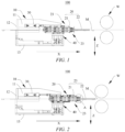
- FIG. 1 is a schematic diagram of a first heating module 20 of a heating device 100 according to some embodiments of the present application at a second position
- FIG. 2 is a schematic diagram of the first heating module 20 of the heating device 100 according to some embodiments of the present application at a first position.
- the present application provides a heating device 100 for heating a separator M upstream of a first station W.
- the heating device 100 includes a support 10, a first heating module 20, and a first driving module 30.
- the first heating module 20 is movably mounted to the support 10.
- the first driving module 30 is mounted to the support 10, and the first driving module 30 is configured to drive the first heating module 20 to move in a feeding direction X of the separator M, such that the first heating module 20 is movable between a first position close to the first station W and a second position away from the first station W.
- a direction indicated by X in the figure is a feeding direction of the separator M, which is called the feeding direction X for short.
- the heating device 100 provided upstream of the first station W means a sequential relationship between the heating device 100 and the first station W during processing of the separator M, that is, the separator M is heated by the heating device 100 and then conveyed to the first station W for processing.
- the support 10 provides positioning support to facilitate mounting and positioning of the first heating module 20 and the first driving module 30.
- the first heating module 20 is movable relative to the support 10 in the feeding direction X of the separator M.
- the first heating module 20 has the first position and the second position in the feeding direction X, with the first position close to the first station Wand the second position away from the first station W.
- the first driving module 30 is mounted to the support 10, and the first driving module 30 is configured to drive the first heating module 20 to move in the feeding direction X of the separator M, such that the first heating module 20 is movable between the first position and the second position, thus changing the position of the first heating module 20.
- the heating device 100 is provided upstream of the first station W, when the heating device 100 operates normally, as shown in FIG. 1 , the first heating module 20 is located at the second position, and after shutdown and before operation, the first driving module 30 drives the first heating module 20 from the second position to the first position, as shown in FIG. 2 , such that the first heating module 20 heats the separator M at the first position to ensure that a temperature of the separator M entering the first station W satisfies process requirements of the first station W, the problem of occurrence of waste products due to that a temperature of the part of the separator M between the heating device 100 and the first station W does not satisfy the process requirements is solved, and material waste and manufacturing cost are reduced.
- the separator M is conveyed in a horizontal direction, and a thickness direction Z of the separator M is parallel to a vertical direction, so as to facilitate conveying and heating of the separator M.
- the separator M conveyed in the horizontal direction means that a feeding trend of the separator M is horizontal, but the separator M is not always conveyed in the horizontal direction.
- a direction indicated by Z in the figure is the thickness direction of the separator M.
- an output end of the first driving module 30 is configured to reciprocate in the feeding direction X of the separator M.
- the first driving module 30 may be a driving structure such as an air cylinder, a hydraulic cylinder, or an electric push rod, or a driving structure in which an electric motor cooperate with a transmission assembly, wherein the transmission assembly may be a rack and pinion transmission assembly, a screw and nut transmission assembly, a belt transmission assembly, a chain transmission assembly, etc.
- the first driving module 30 may be an air cylinder, which is simple in structure and easy to assemble.
- the first driving module 30 may be located above the separator M or below the separator M.
- the first heating module 20 includes a first heating unit 21 and a second heating unit 22 connected to each other, wherein the first heating unit 21 and the second heating unit 22 are sequentially arranged in the feeding direction X, the second heating unit 22 is closer to the first station W than the first heating unit 21, and a surface of the second heating unit 22 away from the separator M is closer to the separator M than a surface of the first heating unit 21 away from the separator M.
- the first heating unit 21 and the second heating unit 22 are sequentially arranged in the feeding direction X, so as to form two heating areas.
- the second heating unit 22 is closer to the first station W than the first heating unit 21.
- the second heating unit 22 may heat the separator M at a position closer to the first station W, so as to ensure that the process requirements of the first station W may be satisfied when the separator M enters the first station W.
- a surface of the second heating unit 22 close to the separator M and a surface of the first heating unit 21 close to the separator M may be coplanar, so as to ensure that the first heating unit 21 and the second heating unit 22 have the same distance from the separator M.
- the surface of the second heating unit 22 away from the separator M is closer to the separator M than the surface of the first heating unit 21 away from the separator M.
- the second heating unit 22 has a smaller occupied volume than the first heating unit 21.
- the second heating unit 22 may extend into narrower space environment, such as an entry to the first station W, and the first position may be closer to the first station W, such that the first heating module 20 can heat the separator M at a position closer to the first station W.
- FIG. 3 is an enlarged view of part A of FIG. 2 .
- the first heating unit 21 and the second heating unit 22 are detachably connected to each other.
- the first heating unit 21 and the second heating unit 22 are connected by means of a threaded fastener 29, and alternatively, the first heating unit 21 is engaged with the second heating unit 22.
- a surface of the first heating unit 21 facing the separator M may be provided with a stepped slot 210, the stepped slot 210 is located at an end of the first heating unit 21 close to one end of the second heating unit 22, the second heating unit 22 may extend into the stepped slot 210, and the first heating unit 21 overlaps with the second heating unit 22, so as to ensure that the first heating unit 21 and the second heating unit 22 are connected stably.
- the first heating unit 21 has higher heating power than the second heating unit 22.
- the second heating unit 22 cannot have high heating power.
- the first heating module 20 moves to the first position, the second heating unit 22 performs preheating, and then the first heating unit 21 is activated after the process temperature is reached. Due to the high heating power of the first heating unit 21, the temperature of the separator M corresponding to the first heating unit 21 increases rapidly. After a start-up temperature is reached, the first heating module 20 moves back to the second position, and conveying of the separator M is started.
- the first heating unit 21 is activated after the second heating unit 22 because the first heating unit 21 has shorter heating time than the second heating unit 22. Waiting time for heating when the heating device 100 operates normally is reduced, thus avoiding damages to the part of the separator M corresponding to the first heating unit 21 due to an excess temperature in the case of the first heating unit 21 and the second heating unit 22 being activated synchronously.
- the first heating unit 21 includes a base plate 211 and a heating member 212 embedded in the base plate 211.
- the heating member 212 may be a heating rod or other structures.
- the second heating unit 22 includes a heating plate 221, and the heating plate 221 may have a heating mode in which a silica gel heating plate 221 is attached to a surface of a metal sheet, such that the second heating unit 22 may extend into narrower space environment.
- the first heating module 20 includes two first heating assemblies 23 arranged oppositely in the thickness direction Z of the separator M, with a first gap 24 for the separator M to pass through being formed between the two first heating assemblies 23.
- the two first heating assemblies 23 are arranged oppositely in the thickness direction Z of the separator M, and the first gap 24 for the separator M to pass through is formed between the two first heating assemblies 23, such that feeding of the separator M in the first gap 24 is facilitated, and two sides of the separator M in the thickness direction Z are heated.
- the two first heating assemblies 23 may heat the separator M on opposite sides of the separator M in the thickness direction Z, such that the separator M is evenly heated to ensure a better heating effect.
- the two first heating assemblies 23 are located above and below the separator M respectively, such that the two first heating assemblies 23 heat the separator M from above and below the separator M.
- the first heating module 20 includes first heating units 21 and second heating units 22
- the number of the first heating units 21 and the number of the second heating units 22 are both two
- the two first heating units 21 are located on two sides of the separator M in the thickness direction Z, respectively
- the two second heating units 22 are located on two sides of the separator M in the thickness direction Z, respectively
- the first heating unit 21 and the second heating unit 22 located on the same side of the separator M form one first heating assembly 23.
- the heating device 100 further includes a second driving module 40 for driving the two first heating assemblies 23 to move close to or away from each other in the thickness direction Z of the separator M to change a size of the first gap 24.
- the size of the first gap 24 indicates a distance between the two first heating assemblies 23 in the thickness direction Z of the separator M.
- the two first heating assemblies 23 may move close to or away from each other in the thickness direction Z of the separator M, such that the size of the first gap 24 is reduced or increased, that is, distances between the first heating assemblies 23 and the separator M are changed.
- the second driving module 40 is configured to provide a driving force, and the second driving module 40 drives the two first heating assemblies 23 to move close to or away from each other in the thickness direction Z of the separator M, such that the size of the first gap 24 may be adjusted depending on different separators M, providing high adaptability to meet heating requirements.
- the first gap 24 is enlarged, such that penetration of the separator M is facilitated, and the production efficiency is improved.
- an output end of the second driving module 40 is configured to reciprocate in the thickness direction Z of the separator M.
- the second driving module 40 may be a driving structure such as an air cylinder, a hydraulic cylinder, or an electric push rod, or a driving structure in which an electric motor cooperate with a transmission assembly, wherein the transmission assembly may be a rack and pinion transmission assembly, a screw and nut transmission assembly, a belt transmission assembly, a chain transmission assembly, etc.
- the second driving module 40 may be a hydraulic cylinder, which is simple in structure and easy to assemble.
- FIG. 4 is a cross-sectional view of a first heating module 20 according to some embodiments of the present application.
- one of the two first heating assemblies 23 is connected to an output end of a first driving module 30, the other one of the two first heating assemblies is connected to an output end of a second driving module 40, and the two first heating assemblies 23 are slidably connected to each other in a thickness direction Z of the separator M.
- the two first heating assemblies 23 are connected to the first driving module 30 and the second driving module 40, respectively, that is, the first driving module 30 acts on one of the two first heating assemblies 23, and the second driving module 40 acts on the other one of the two first heating assemblies 23.
- the first driving module 30 and the second driving module 40 may be arranged on two sides of the separator M in the thickness direction Z, so as to facilitate use for corresponding heating assemblies.
- the two first heating assemblies 23 are slidably connected to each other in the thickness direction Z of the separator M, the two first heating assemblies 23 may slide relative each other in the thickness direction Z of the separator M, and the two first heating assemblies 23 may synchronously move in the feeding direction X of the separator M under the action of the first driving module 30.
- the two first heating assemblies 23 are connected to the first driving module 30 and the second driving module 40, respectively, so as to reduce space occupation.
- the first driving module 30 and the second driving module 40 may be located on two sides of the separator M in the thickness direction Z, and the positions of the first driving module 30 and the second driving module 40 are rationally arranged to provide a rational configuration and a simple structure.
- the first driving module 30 may be arranged above the separator M, and the second driving module 40 may be arranged below the separator M.
- the other one of the two first heating assemblies 23 is slidably connected to the output end of the second driving module 40 in the feeding direction X.
- the two first heating assemblies 23 are connected to the first driving module 30 and the second driving module 40, respectively, wherein the first heating assembly 23 connected to the second driving module 40 is slidably connected to the output end of the second driving module 40 in the feeding direction X, and the first heating assembly 23 can move relative to the output end of the second driving module 40 in the feeding direction X. That is, when the two first heating assemblies 23 move in the feeding direction X of the separator M under the action of the first driving module 30, the first heating assembly 23 connected to the second driving module 40 can move relative to the second driving module 40.
- the other one of the two first heating assemblies 23 is slidably connected to the output end of the second driving module 40, such that the two first heating assemblies 23 are driven by the first driving module 30 to move stably in the feeding direction X relative to a support 10 to prevent a movement of the second driving module 40 along with the first heating assemblies 23, which results in interference between components, unstable movement and thus potential safety hazards.
- the support 10 includes a first sub-support 11, a second sub-support 12, and a third sub-support 13.
- the second sub-support 12 is arranged in the thickness direction Z of the separator M and is located on one side of the separator M in a width direction Y (see FIG. 8 ).
- the first sub-support 11 and the third sub-support 13 are connected to two ends of the second sub-support 12 in the thickness direction Z of the separator M, respectively.
- the first sub-support 11 and the third sub-support 13 each are arranged in parallel with the separator M.
- the separator M is located between the first sub-support 11 and the third sub-support 13.
- a direction indicated by Y in FIG. 8 is the width direction of the separator M.
- the first driving module 30 may be arranged on the first sub-support 11, and the second driving module 40 may be arranged on the third sub-support 13.
- one of the two first heating assemblies 23 is slidably connected to the first sub-support 11, and the other one of the two first heating assemblies is slidably connected to the output of the second driving module 40.
- the first sub-support 11 may be slidably connected to a corresponding first heating assembly 23 by means of a first sliding block and rail 25
- the output end of the second driving module 40 may be slidably connected to a corresponding first heating assembly 23 by means of a second sliding block and rail 41.
- one of the two first heating assemblies 23 may be provided with a protrusion, and the other one of the two first heating assemblies may be provided with an open recess for inserting the protrusion in the thickness direction Z of the separator M, such that the two first heating assemblies 23 may slide relative to each other in the thickness direction Z of the separator M, and the two first heating assemblies 23 may move synchronously in the feeding direction X.
- FIG. 5 is a schematic diagram of connection of two first heating assemblies 23 according to some embodiments of the present application
- FIG. 6 is an enlarged view of part B of FIG. 5
- one of the two first heating assemblies 23 is provided with two first limiting blocks 26, the other one of the two first heating assemblies is provided with a second limiting block 27, and a slot 28 for inserting the second limiting block 27 in a thickness direction Z of a separator M is formed between the two first limiting blocks 26.
- the first limiting blocks 26 and the second limiting block 27 are located on the same side of the separator M in a width direction Y (see FIG. 8 ).
- one of the two first heating assemblies 23 is provided with the two first limiting blocks 26, and the other one of the two first heating assemblies is provided with the second limiting block 27.
- the first heating assembly 23 located above the separator M may be provided with the second limiting block 27, and the first heating assembly 23 located below the separator M may be provided with the two first limiting blocks 26.
- the two first limiting blocks 26 are provided at a distance from each other in a feeding direction X of the separator M, and the slot 28 for inserting the second limiting block 27 in the thickness direction Z of the separator M is formed between the two first limiting blocks 26, such that the second limiting block 27 may be inserted into the slot 28 in the thickness direction Z of the separator M.
- the second limiting block 27 After the second limiting block 27 is inserted into the slot 28, two sides of the second limiting block 27 are limited by the two first limiting blocks 26 in the feeding direction X of the separator M, and the second limiting block 27 cannot move relative to the two first limiting blocks 26 in the feeding direction X, and alternatively, even if the second limiting block 27 is movable in the slot 28, the amount of movement of the second limiting block 27 is small. Therefore, when a first driving module 30 drives a first heating module 20 to move, the two first limiting blocks 26 cooperate with the second limiting block 27 to allow the two first heating assemblies 23 to synchronously move in the feeding direction X.
- the two first limiting blocks 26 define the slot 28 for inserting the second limiting block 27 in the thickness direction Z of the separator M.
- relative movements of the two first heating assemblies 23 may be guided, and stable relative movements of the two first heating assemblies 23 are ensured; and on the other hand, the two first heating assemblies 23 may be further connected in the feeding direction X of the separator M to ensure that the two first heating assemblies 23 can move synchronously in the feeding direction X of the separator M.
- the first limiting blocks 26 may be detachably connected to corresponding first heating assemblies 23, for example, by means of threaded connection, insertion, and engagement.
- the second limiting block 27 may be detachably connected to a corresponding first heating assembly 23, for example, by means of threaded connection, insertion, and engagement.
- the first limiting blocks 26 may be integrally formed on the corresponding first heating assemblies 23, and the second limiting block 27 may also be integrally formed on the corresponding first heating assembly 23.
- the second limiting block 27 may be a protrusion, and the slot 28 formed between the two first limiting blocks 26 may be an open recess.
- the open recess may be a recess formed on a corresponding first heating assembly 23.
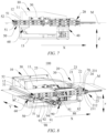
- FIG. 7 is a schematic structural diagram of the first heating module 20 of the heating device 100 according to some other embodiments of the present application at a second position.
- the heating device 100 further includes a second heating module 50, and the second heating module 50 is mounted to a support 10 and located upstream of the first heating module 20.
- the second heating module 50 is located upstream of the first heating module 20, and the separator M passes by the second heating module 50 and then passes by the first heating module 20 in the feeding direction X of the separator M.
- the second heating module 50 is configured to heat the separator M.
- the second heating module 50 and the first heating module 20 are used cooperatively, so as to increase a heating area for the separator M in the feeding direction X of the separator M and improve the heating efficiency.
- the second heating module 50 includes two second heating assemblies 51 arranged oppositely in the thickness direction Z of the separator M, and a second gap 52 for the separator M to pass through is formed between the two second heating assemblies 51.
- the two second heating assemblies 51 are arranged oppositely in the thickness direction Z of the separator M, and the second gap 52 for the separator M to pass through is formed between the two second heating assemblies 51, such that feeding of the separator M in the second gap 52 is facilitated, and two sides of the separator M in the thickness direction Z are heated.
- the two second heating assemblies 51 may heat the separator M on opposite sides of the separator M in the thickness direction Z, such that the separator M is evenly heated to ensure a better heating effect.
- the two second heating assemblies 51 are symmetrically distributed on two sides of the separator M.
- distances between the second heating assemblies 51 and the separator M may be equal to the distances between the first heating assemblies 23 and the separator M.
- distances between the second heating assemblies 51 and the separator M may be unequal to the distances between the first heating assemblies 23 and the separator M.
- the second gap 52 for the separator M to pass through is formed between the two second heating assemblies 51, such that the separator M may be heated on opposite sides of the separator M, and a desirable heating effect is provided.
- the heating device 100 further includes a third driving module 60, and the third driving module 60 is mounted to the support 10 to drive the two second heating assemblies 51 to move close to or away from each other in the thickness direction Z of the separator M, so as to change a size of the second gap 52.
- the size of the second gap 52 indicates the distance between two second heating assemblies 51 in the thickness direction Z of the separator M.
- the two second heating assemblies 51 may move close to or away from each other in the thickness direction Z of the separator M, such that the size of the second gap 52 is reduced or increased, that is, the distances between the second heating assemblies 51 and the separator M are changed.
- the third driving module 60 is configured to provide a driving force, and the third driving module 60 drives the two second heating assemblies 51 to move close to or away from each other in the thickness direction Z of the separator M, such that the size of the second gap 52 may be adjusted depending on different separators M, providing high adaptability to meet heating requirements.
- the second gap 52 is enlarged, such that penetration of the separator M is facilitated, and the production efficiency is improved.
- the separator M is conveyed in a horizontal direction and the support 10 includes a first sub-support 11, a second sub-support 12 and a third sub-support 13
- the two second heating assemblies 51 are located on two sides of the separator M in the thickness direction Z
- the second heating assembly 51 located above the separator M is mounted to the second sub-support 12
- the third driving module 60 is mounted to the third sub-support 13
- the second heating assembly 51 located below the separator M is connected to an output end of the third driving module 60
- the third driving module 60 drives the second heating assembly 51 located below the separator M to move in the thickness direction Z of the separator M.
- the output end of the third driving module 60 is configured to reciprocate in the thickness direction Z of the separator M.
- the third driving module 60 may be a driving structure such as an air cylinder, a hydraulic cylinder, or an electric push rod, or a driving structure in which an electric motor cooperate with a transmission assembly, wherein the transmission assembly may be a rack and pinion transmission assembly, a screw and nut transmission assembly, a belt transmission assembly, a chain transmission assembly, etc.
- the third driving module 60 may be a hydraulic cylinder, which is simple in structure and easy to assemble.
- FIG. 8 is a schematic structural diagram of a heating device 100 according to some embodiments of the present application.
- the heating device 100 further includes a detection unit 80 and a position adjustment module 90.
- the detection unit 80 is configured to detect offset information of an edge of a separator M.
- the position adjustment module 90 is configured to adjust a position of the detection unit 80 in a width direction Y of the separator M.
- the offset information of the edge of the separator M refers to position information of the edge of the separator M relative to a support 10 in the width direction Y of the separator M, that is, information of the distance from the edge of the separator M to the support 10.
- the distance between the edge of the separator M and the support 10 has a preset value.
- the detection unit 80 detects the offset information of the edge of the separator M, i.e., by comparing the distance between the edge of the separator M and the support 10 with the preset value. If the distance between the edge of the separator M and the support 10 which is detected by the detection unit 80 is greater than or smaller than the preset value, the edge of the separator M is offset.
- the detection unit 80 detects the offset information of the edge of the separator M, so as to know a conveying condition of the separator M, facilitate adjustment of the separator M, and ensure a heating effect of the separator M.
- the position adjustment module 90 is configured to adjust the position of the detection unit 80 in the width direction Y of the separator M, such that the detection unit 80 may detect the offset information of the edge of the separator M to adapt to separators M having different specifications, providing a high adaptability.
- FIG. 9 is a cross-sectional view of a heating device 100 according to some embodiments of the present application.
- two first heating assemblies 23 are provided with a first opening 231 therethrough in a thickness direction Z of a separator M and a second opening 232 therethrough in the thickness direction Z of the separator M, respectively, the first opening 231 corresponds to the second opening 232 in position
- the heating device 100 further includes a light source 70, the light source 70 is arranged at the first opening 231, a detection unit 80 includes a camera 81, and the camera 81 is configured to acquire image information of an edge of the separator M through the second opening 232.
- One of the two first heating assemblies 23 is provided with the first opening 231, and the other one of the two first heating assemblies is provided with the second opening 232.
- the first opening 231 and the second opening 232 are provided through corresponding first heating assemblies 23, respectively, and projections of the first opening 231 and the second opening 232 in the thickness direction Z of the separator M coincide.
- the camera 81 configured to acquire the image information of the edge of the separator M through the second opening 232 means that the camera 81 acquires the image information of the edge of the separator M through the second opening 232, in other words, the camera 81 and the light source 70 are located on two sides of the separator M in the thickness direction Z, respectively, that is, the camera 81 corresponds to one of the two first heating assemblies 23, and the light source 70 corresponds to the other one of the two first heating assemblies 23.
- a support 10 includes a first sub-support 11, a second sub-support 12 and a third sub-support 13
- the camera 81 may be arranged on the third sub-support 13, and the first heating assembly 23 corresponding to the light source 70 may be arranged on the first sub-support 11.
- the camera 81 acquires an image of the edge of the separator M when a first heating module 20 is located at a second position.
- the camera 81 acquires the image information of the edge of the separator M and analyzes a position of the edge of the separator M, so as to determine offset information of the edge of the separator M.
- the light source 70 provides backlight for the camera 81 for a clear image acquired by the camera 81.
- the light source 70 and the camera 81 are arranged on opposite sides of the separator M, respectively, such that the camera 81 may acquire the image of the edge of the separator M, and the accuracy of the image is ensured.
- the first opening 231 and the second opening 232 extend in a width direction Y of the separator M, such that the camera 81 may acquire image information of more areas.
- FIG. 10 is a schematic structural diagram of a detection unit 80 according to some embodiments of the present application.
- the detection unit 80 further includes a reflector 82, and the reflector 82 is arranged at a second opening 232 and is configured to reflect an image of an edge of a separator M to a camera 81.
- a transmission path for light may be a broken line, and a light source 70 and the camera 81 may not need to be arranged in line, such that a position of the camera 81 may be rationally arranged to provide a rational configuration and less space occupation.
- a position adjustment module 90 includes an adjustment handle 91, a lead screw 92, and a nut 93.
- the lead screw 92 is rotatably mounted to a support 10, the lead screw 92 extends in the width direction Y of the separator M, the adjustment handle 91 is connected to one end of the lead screw 92, the nut 93 is sleeved on the lead screw 92 and is in threaded connection with the lead screw 92, and the detection unit 80 is connected to the nut 93.
- the camera 81 and the reflector 82 are connected to the nut 93.
- the adjustment handle 91 is driven to rotate to drive the lead screw 92 to rotate, and the nut 93 moves along the lead screw 92, such that the detection unit 80 moves along the lead screw 92, and the position of the detection unit 80 in the width direction Y of the separator M may be adjusted.
- the adjustment handle 91 drives the lead screw 92 to rotate to adjust the position of the detection unit 80 to allow for easy and inexpensive adjustment.
- a transmission mode of the lead screw 92 and the nut 93 facilitates precise control of the position of the detection unit 80.
- the lead screw 92 is rotatably mounted to the third sub-support 13.
- the third sub-support 13 is located below the separator M, and each of the position adjustment module 90, the camera 81 and the reflector 82 is located below the separator M, so as to reduce space occupation above the separator M.
- the position adjustment module 90 further includes a hoop locking assembly 94, and the hoop locking assembly 94 is configured to lock the lead screw 92 to limit rotation of the lead screw 92 relative to the support 10.
- the hoop locking assembly 94 is used to lock the lead screw 92, which is convenient to operate and improves the production efficiency.
- the locking assembly may also be other locking structures, such as a limiting pin and a limiting clamp, as long as the rotation of the lead screw 92 relative to the support 10 may be limited.
- the adjustment handle 91 may also be replaced with a driving motor, and the driving motor may drive the lead screw 92 to rotate.
- the driving motor may drive the lead screw 92 to rotate.
- the number of detection units 80 is two, and the two detection units 80 are arranged at a distance from each other in the width direction Y of the separator M (see FIG. 8 ), and each detection unit 80 detects offset information of one edge of the separator M in the width direction Y.
- the number of position adjustment modules 90 is two, and the two position adjustment modules 90 are in one-to-one correspondence to the two detection units 80.
- the adjustment handles 91 of the two position adjustment modules 90 may be arranged on the same side of the separator M in the width direction Y to facilitate operations. Alternatively, the adjustment handles 91 of the two position adjustment modules 90 may be arranged on two sides of the separator M in the width direction Y.
- the present application provides a heating device 100.
- the heating device 100 includes a support 10, a first heating module 20, a first driving module 30, a second driving module 40, a second heating module 50, a third driving module 60, a light source 70, a detection unit 80, and a position adjustment module 90.
- the support 10 includes a first sub-support 11, a second sub-support 12, and a third sub-support 13.
- a separator M is conveyed in a horizontal direction.
- the second sub-support 12 is arranged in a thickness direction Z of the separator M.
- the first sub-support 11 and the third sub-support 13 are arranged at two ends of the second sub-support 12 in the thickness direction Z of the separator M.
- the first sub-support 11 and the third sub-support 13 are arranged in parallel with the separator M.
- the first driving module 30 is mounted to the first sub-support 11, and the second driving module 40 is arranged on the third sub-support 13.
- the first heating module 20 includes a first heating unit 21 and a second heating unit 22 connected in a feeding direction X of the separator M.
- the second heating unit 22 is closer to a first station W than the first heating unit 21, and a surface of the second heating unit 22 away from the separator M is closer to the separator M than a surface of the first heating unit 21 away from the separator M, such that the second heating unit 22 may extend into narrower space environment.
- the first heating module 20 includes two first heating assemblies 23 arranged oppositely in the thickness direction Z of the separator M, a first gap 24 for the separator M to pass through is formed between the two first heating assemblies 23, and the second driving module 40 is configured to drive two first heating units 21 to move close to or away from each other to change a size of the first gap 24.
- One of the two first heating assemblies 23 is located above the separator M.
- the first heating assembly 23 is slidably connected to an output end of the first driving module 30 in the feeding direction X of the separator M.
- the first heating assembly 23 is slidably connected to the support 10.
- the other one of the two first heating assemblies 23 is located below the separator M.
- the first heating assembly 23 is slidably connected to an output end of the second driving module 40 in the feeding direction X of the separator M.
- the first heating assembly 23 located above the separator M is slidably connected to the first heating assembly 23 located below the separator.
- the first heating assembly 23 located above the separator M is provided with a second limiting block 27, the first heating assembly 23 located below the separator M is provided with two first limiting blocks 26, and a slot 28 for inserting the second limiting block 27 in the thickness direction Z of the separator M is formed between the two first limiting blocks 26.
- the first limiting blocks 26 cooperate with the second limiting block 27 to enable the two first heating assemblies 23 to move close to or away from each other, and the two first heating assemblies 23 may synchronously move in the feeding direction X of the separator M.
- the second heating module 50 is arranged upstream of the first heating module 20, the second heating module 50 includes two second heating assemblies 51 arranged oppositely in the thickness direction Z of the separator M, a second gap 52 for the separator M to pass through is formed between the two second heating assemblies 51, and the third driving module 60 is configured to drive the two second heating assemblies 51 to move close to or away from each other to change a size of the second gap 52.
- the second heating assembly 51 located above the separator M is mounted to the second sub-support 12
- the third driving module 60 is mounted to the third sub-support 13
- the second heating assembly 51 located below the separator M is connected to an output end of the third driving module 60.
- the two first heating assemblies 23 are provided with a first opening 231 therethrough in the thickness direction Z of the separator M and a second opening 232 therethrough in the thickness direction Z of the separator M, respectively, the first opening 231 is in the first heating assembly 23 located above the separator M, and the second opening 232 is in the first heating assembly 23 located below the separator M.
- the light source 70 is arranged at the first opening 231.
- each detection unit 80 includes a camera 81 and a reflector 82, and the camera 81 is configured to acquire image information of an edge of the separator M through the second opening 232.
- the reflector 82 is arranged at the second opening 232 and is configured to reflect an image of the edge of the separator M to the camera 81.
- the position adjustment module 90 includes an adjustment handle 91, a lead screw 92, and a nut 93.
- the lead screw 92 is rotatably mounted to the third sub-support 13, the lead screw 92 extends in the width direction Y of the separator M, the adjustment handle 91 is connected to one end of the lead screw 92, the nut 93 is sleeved on the lead screw 92 and is in threaded connection with the lead screw 92, and the camera 81 and the reflector 82 are connected to the nut 93.
- the adjustment handle is rotated to adjust a position of the detection unit 80 in the width direction Y of the separator M, so as to adapt to separators M having different specifications.
- FIG. 11 is a schematic diagram of a first heating module 20 of a battery manufacturing apparatus 1000 according to some embodiments of the present application at a second position
- FIG. 12 is a schematic diagram of the first heating module 20 of the battery manufacturing apparatus 1000 according to some embodiments of the present application at a first position.
- the present application further provides a battery manufacturing apparatus 1000.
- the battery manufacturing apparatus 1000 includes a conveying device (not shown), a hot pressing device 300, and the heating device 100 described in any one of the solutions.
- the conveying device is configured to convey a separator M.
- the heating device 100 is configured to heat the separator M.
- the hot pressing device 300 is located at a first station W, and the hot pressing device 300 is configured to bonding a plate P to the separator M by hot pressing.
- the hot pressing device 300 includes two hot pressing rollers 310.
- the two hot pressing rollers 310 are arranged at a distance from each other in a thickness direction of the separator M, the two hot pressing rollers 310 are configured to roll the plate P and the separator M so as to bond the plate P to the separator M by hot pressing.
- FIG. 13 is a schematic flow diagram of a battery manufacturing method according to some embodiments of the present application.
- the present application further provides a battery manufacturing method, which uses the battery manufacturing apparatus 1000 described above. As shown in FIG. 13 , the battery manufacturing method includes the following steps.
- a first heating module 20 is moved to a first position to preheat the part of a separator M between a heating device 100 and a hot pressing device 300.
- the first heating module 20 is moved to a second position to heat the separator M, and a conveying device is operated.
- the first position is closer to a first station W than the second position, and the hot pressing device 300 is located at the first station W.
- a first driving module 30 drives the first heating module 20 to move to the first position relative to the support 10 in a feeding direction X of the separator M, a second heating unit 22 of the first heating module 20 is activated to preheat the separator M, after the temperature at the separator M satisfies process requirements, a first heating unit 21 is activated, and after the temperature reaches a start-up temperature, preheating of the separator M is completed.
- the first heating module 20 is moved to the second position, the conveying device is operated to convey the separator M, and the first heating module 20 and a second heating module 50 together heat the separator M.
Landscapes
- Engineering & Computer Science (AREA)
- Manufacturing & Machinery (AREA)
- Chemical & Material Sciences (AREA)
- Chemical Kinetics & Catalysis (AREA)
- Electrochemistry (AREA)
- General Chemical & Material Sciences (AREA)
- Secondary Cells (AREA)
- Lining Or Joining Of Plastics Or The Like (AREA)
- Sealing Battery Cases Or Jackets (AREA)
- Battery Mounting, Suspending (AREA)
Abstract
Description
- The present application claims the priority of
Chinese patent application No. 202111017127.0, filed on August 31, 2021 - The present application relates to the technical field of battery manufacturing, and particularly relates to a heating device, and a battery manufacturing apparatus and method.
- During battery production, it is necessary to perform thermal processing on a material strip. Usually, a heating device is used to heat the material strip at a station before a thermal processing station.
- During production, material waste is likely to occur, which results in high manufacturing cost.
- An objective of the present application is to provide a heating device, and a battery manufacturing apparatus and method. The heating device reduces material waste, and saves manufacturing cost.
- The present application is achieved by the following technical solutions.
- In a first aspect, an embodiment of the present application provides a heating device for heating a material strip upstream of a first station, the heating device including: a support; a first heating module movably mounted to the support; and a first driving module mounted to the support and configured to drive the first heating module to move in a feeding direction of the material strip, such that the first heating module is movable between a first position close to the first station and a second position away from the first station.
- The heating device according to the embodiment of the present application is arranged upstream of the first station, and after shutdown and before operation, the first driving module drives the first heating module from the second position to the first position, such that the first heating module heats the material strip at the first position to ensure that a temperature of the material strip entering the first station satisfies process requirements of the first station, the problem of occurrence of waste products due to that a temperature of the part of the material strip between the heating device and the first station does not satisfy the process requirements is solved, and material waste and manufacturing cost are reduced.
- According to some embodiments of the present application, the first heating module comprises a first heating unit and a second heating unit connected to each other, the first heating unit and the second heating unit being sequentially arranged in the feeding direction, the second heating unit being closer to the first station than the first heating unit, and a surface of the second heating unit away from the material strip being closer to the material strip than a surface of the first heating unit away from the material strip.
- In the above solution, the surface of the second heating unit away from the material strip is closer to the material strip than the surface of the first heating unit away from the material strip, such that the second heating unit occupies small space in a thickness direction of the material strip. By contrast with the same space occupied by the second heating unit and the first heating unit, in this solution, the second heating unit may extend into narrower space environment, and the first position may be closer to the first station, such that the first heating module may be closer to the first station.
- According to some embodiments of the present application, the first heating unit has higher heating power than the second heating unit.
- In the solution, because the second heating unit has a small occupied volume and limited structural space, the second heating unit cannot have high heating power. After shutdown and before operation, the second heating unit in the first heating module at the first position performs preheating, and then the first heating unit is activated. The first heating unit has shorter heating time than the second heating unit, such that waiting time for heating when the heating device operates normally is reduced, thus avoiding damages to the part of the material strip corresponding to the first heating unit due to an excess temperature in the case of the first heating unit and the second heating unit being activated synchronously.
- According to some embodiments of the present application, the first heating module includes two first heating assemblies arranged oppositely in a thickness direction of the material strip, and a first gap for the material strip to pass through is formed between the two first heating assemblies.
- In the solution, the first gap is formed between the two first heating assemblies for the material strip to conveniently pass through, such that the material strip may be heated on opposite sides of the material strip, and a desirable heating effect is provided.
- According to some embodiments of the present application, the heating device further includes: a second driving module for driving the two first heating assemblies to move close to or away from each other in the thickness direction of the material strip to change a size of the first gap.
- In the above solution, the second driving module drives the two first heating assemblies to move close to or away from each other, such that the size of the first gap may be adjusted depending on different material strips, providing high adaptability to meet heating requirements. In addition, the first gap is enlarged, such that penetration of the material strip is facilitated, and the production efficiency is improved.
- According to some embodiments of the present application, one of the two first heating assemblies is connected to an output end of the first driving module, the other one of the two first heating assemblies is connected to an output end of the second driving module, and the two first heating assemblies are slidably connected to each other in the thickness direction of the material strip.
- In the above solution, the two first heating assemblies are connected to the first driving module and the second driving module, respectively, the positions of the first driving module and the second driving module are rationally arranged to provide a rational configuration and a simple structure.
- According to some embodiments of the present application, the other one of the two first heating assemblies is slidably connected to the output end of the second driving module in the feeding direction.
- In the above solution, the other one of the two first heating assemblies is slidably connected to the output end of the second driving module, such that the two first heating assemblies are driven by the first driving module to move stably in the feeding direction relative to a support to prevent a movement of the second driving module along with the first heating assemblies, which results in interference between components, unstable movement and thus potential safety hazards.
- According to some embodiments of the present application, one of the two first heating assemblies is provided with two first limiting blocks, the other one of the two first heating assemblies is provided with a second limiting block, and a slot for inserting the second limiting block in the thickness direction of the material strip is formed between the two first limiting blocks.
- In the above solution, the two first limiting blocks define the slot for inserting the second limiting block in the thickness direction of the material strip. On one hand, relative movements of the two first heating assemblies may be guided, and on the other hand, the two first heating assemblies may be further connected in the feeding direction of the material strip to ensure that the two first heating assemblies can move synchronously in the feeding direction of the material strip.
- According to some embodiments of the present application, the heating device further includes: a second heating module mounted to the support and located upstream of the first heating module.
- In the above solution, the second heating module is located upstream of the first heating module. The arrangement of the second heating module enables to increase a heating area for the material strip and improve the heating efficiency.
- According to some embodiments of the present application, the second heating module includes two second heating assemblies arranged oppositely in a thickness direction of the material strip, and a second gap for the material strip to pass through is formed between the two second heating assemblies.
- In the above solution, the second gap for the material strip to pass through is formed between the two second heating assemblies, such that the material strip may be heated on opposite sides of the material strip, and a desirable heating effect is provided.
- According to some embodiments of the present application, the heating device further includes: a third driving module mounted to the support and configured to drive the two second heating assemblies to move close to or away from each other in the thickness direction of the material strip to change a size of the second gap.
- In the above solution, the third driving module drives the two second heating assemblies to move close to or away from each other in the thickness direction of the material strip, such that the size of the second gap may be adjusted depending on different material strips, providing high adaptability to meet heating requirements. Meanwhile, the second gap is enlarged, such that penetration of the material strip is facilitated, and the production efficiency is improved.
- According to some embodiments of the present application, the heating device further includes: a detection unit configured to detect offset information of an edge of the material strip; and a position adjustment module configured to adjust a position of the detection unit in a width direction of the material strip.
- In the above solution, the detection unit detects the offset information of the edge of the material strip to know a conveying condition of the material strip; and the position adjustment module adjusts the position of the detection unit in the width direction of the material strip for adaptability to the detection of material strips of different specifications.
- According to some embodiments of the present application, the two first heating assemblies are provided with a first opening therethrough in the thickness direction of the material strip and a second opening therethrough in the thickness direction of the material strip, respectively, the first opening corresponds to the second opening in position, the heating device further comprises a light source arranged at the first opening, and the detection unit comprises a camera configured to acquire an image of the edge of the material strip through the second opening.
- In the above solution, the light source and the camera are arranged on the opposite sides of the material strip, respectively, such that the camera may acquire the image of the edge of the material strip, and the accuracy of the image is ensured.
- According to some embodiments of the present application, the detection unit further includes a reflector arranged at the second opening for reflecting the image of the edge of the material strip to the camera.
- In the above solution, the reflector is arranged at the second opening, such that the position of the camera may be rationally arranged, providing a rational configuration and less space occupation.
- According to some embodiments of the present application, the position adjustment module comprises an adjustment handle, a lead screw, and a nut, the lead screw being rotatably mounted to the support, the lead screw extending in the width direction of the material strip, the adjustment handle being connected to one end of the lead screw, the nut being sleeved on the lead screw and in threaded connection with the lead screw, and the detection unit being connected to the nut.
- In the above solution, the adjustment handle drives the lead screw to rotate to adjust the position of the detection unit to allow for easy adjustment; and a transmission mode of the lead screw and the nut facilitates precise control of the position of the detection unit.
- In a second aspect, an embodiment of the present application further provides a battery manufacturing apparatus, including: a conveying device for conveying a separator; the heating device according to any one of the above solutions, wherein the heating device is configured to heat the separator; and a hot pressing device located at the first station and configured to bonding a plate to the separator by hot pressing.
- In a third aspect, an embodiment of the present application further provides a battery manufacturing method, including: after shutdown and before operation, moving a first heating module to a first position to preheat the part of a separator between a heating device and a hot pressing device; and after the preheating is completed, moving the first heating module to a second position to heat the separator, and operating a conveying device.
- Some of the additional aspects and advantages of the present application will be set forth in the following description, and some will become apparent from the following description, or be learned by practice of the present application.
- In order to more clearly describe the technical solutions of embodiments of the present application, the accompanying drawings required in the embodiments will be described briefly below. It should be understood that the following accompanying drawings illustrate only some embodiments of the present application and therefore should not be construed as a limitation on the scope thereof. For those of ordinary skill in the art, other relevant accompanying drawings can also be obtained from these accompanying drawings without any creative effort.
-
FIG. 1 is a schematic diagram of a first heating module of a heating device according to some embodiments of the present application at a second position; -
FIG. 2 is a schematic diagram of the first heating module of the heating device according to some embodiments of the present application at a first position; -
FIG. 3 is an enlarged view of part A ofFIG. 2 ; -
FIG. 4 is a cross-sectional view of a first heating module according to some embodiments of the present application; -
FIG. 5 is a schematic diagram of connection of two first heating assemblies according to some embodiments of the present application; -
FIG. 6 is an enlarged view of part B ofFIG. 5 ; -
FIG. 7 is a schematic structural diagram of a heating device according to some other embodiments of the present application at a second position; -
FIG. 8 is a schematic structural diagram of a heating device according to some embodiments of the present application; -
FIG. 9 is a cross-sectional view of a heating device according to some embodiments of the present application; -
FIG. 10 is a schematic structural diagram of a detection unit according to some embodiments of the present application; -
FIG. 11 is a schematic diagram of a first heating module of a battery manufacturing apparatus according to some embodiments of the present application at a second position; -
FIG. 12 is a schematic diagram of the first heating module of a battery manufacturing apparatus according to some embodiments of the present application at a first position; and -
FIG. 13 is a schematic flow diagram of a battery manufacturing method according to some embodiments of the present application. - In the accompanying drawings, the figures are not drawn to scale.
- List of reference signs: 100-heating device; 10-support; 11-first sub-support; 12-second sub-support; 13-third sub-support; 20-first heating module; 21-first heating unit; 210-stepped slot; 211-base plate; 212-heating member; 22-second heating unit; 221-heating plate; 23-first heating assembly; 231-first opening; 232-second opening; 24-first gap; 25-first sliding block and rail; 26-first limiting block; 27-second limiting block; 28-slot; 29-threaded fastener; 30-first driving module; 40-second driving module; 41-second sliding block and rail; 50-second heating module; 51-second heating assembly; 52-second gap; 60-third driving module; 70-light source; 80-detection unit; 81-camera; 82-reflector; 90-position adjustment module; 91-adjustment handle; 92-lead screw; 93-nut; 94-hoop locking assembly; 1000-battery manufacturing apparatus; 300-hot pressing device; 310-hot pressing roller; M-separator; P-plate; W-first station.
- Embodiments of the technical solutions of the present application will be described in more detail below with reference to the drawings. The following embodiments are merely intended to more clearly illustrate the technical solutions of the present application, so they merely serve as examples, but are not intended to limit the scope of protection of the present application.
- Unless otherwise defined, all technical and scientific terms used herein have the same meanings as those commonly understood by those skilled in the art to which the present application belongs. The terms used herein are merely for the purpose of describing specific embodiments, but are not intended to limit the present application. The terms "comprising" and "having" and any variations thereof in the description and the claims of the present application as well as the brief description of the accompanying drawings described above are intended to cover non-exclusive inclusion.
- In the description of the embodiments of the present application, the technical terms "first", "second", etc. are merely used for distinguishing different objects, and are not to be construed as indicating or implying relative importance or implicitly indicating the number, particular order or primary-secondary relationship of the technical features modified thereby. In the description of the embodiments of the present application, the phrase "a plurality of' means two or more, unless otherwise explicitly and specifically defined.
- The phrase "embodiment" mentioned herein means that the specific features, structures, or characteristics described in conjunction with the embodiment can be encompassed in at least one embodiment of the present application. The phrase at various locations in the description does not necessarily refer to the same embodiment, or an independent or alternative embodiment exclusive of another embodiment. Those skilled in the art understand explicitly or implicitly that the embodiment described herein may be combined with another embodiment.
- In the description of the embodiments of the present application, the term "and/or" is merely intended to describe the associated relationship of associated objects, indicating that three relationships can exist, for example, A and/or B can include: three instances of A alone, A and B simultaneously, and B alone. In addition, the character "/" herein generally indicates an "or" relationship between the associated objects.
- In the description of the embodiments of the present application, the term "a plurality of' means two or more (including two), similarly the term "a plurality of groups" means two or more groups (including two groups), and the term "a plurality of pieces" means two or more pieces (including two pieces).
- In the description of the embodiments of the present application, the orientation or position relationship indicated by the technical terms "central", "longitudinal", "transverse", "length", "width", "thickness", "upper", "lower", "front"; "rear", "left", "right", "vertical", "horizontal", "top", "bottom", "inner", "outer", "clockwise", "counterclockwise", "axial", "radial", "circumferential", etc. are based on the orientation or position relationship shown in the drawings and are merely intended to facilitate and simplify the description of the embodiments of the present application, rather than indicating or implying that the device or element considered must have a particular orientation or be constructed and operated in a particular orientation, and therefore not to be construed as limiting the embodiments of the present application.
- In the description of the embodiments of the present application, unless otherwise explicitly specified and defined, the technical terms "mounting", "mutual connection", "connection", "fixing", etc. should be understood in a broad sense, for example, they may be a fixed connection, a detachable connection, or an integrated connection; may be a mechanical connection or an electrical connection; and may be a direct connection or an indirect connection through an intermediate medium, and may be communication between interiors of two elements or interaction between the two elements. For those of ordinary skill in the art, the specific meaning of the above terms in the embodiments of the present application can be understood according to specific situations.
- During battery production, a preheating station is provided before a bonding station, and a heating device provided at the preheating station preheats a material strip, such that the material strip entering the bonding station satisfies process requirements of the bonding station. During production, material waste is likely to occur, which results in high manufacturing cost. The inventor found that after the heating device is shut down, a temperature of the material strip between the heating device and a first station (such as the bonding station) downstream thereof decreases, and a process temperature of the first station cannot be satisfied; and after the heating device is shut down and before the heating device is operated, the part of the material strip between the heating device and the first station cannot be heated, which impairs processing quality of a next procedure and results in material waste and high manufacturing cost.
- In view of this, in order to solve the problems of material waste and high manufacturing cost, the inventors design a heating device after intensive study to heat a material strip upstream of the first station. The heating device includes a support, a first heating module, and a first driving module. The first heating module is movably mounted to the support. The first driving module is mounted to the support, and the first driving module is configured to drive the first heating module to move in a feeding direction of the material strip, such that the first heating module is movable between a first position close to the first station and a second position away from the first station.
- In such a heating device, after shutdown and before operation, the first driving module drives the first heating module from the second position to the first position, such that the first heating module heats the material strip at the first position to ensure that a temperature of the material strip entering the first station satisfies process requirements of the first station, the problem of occurrence of waste products due to that a temperature of the part of the material strip between the heating device and the first station does not satisfy the process requirements is solved, and material waste and manufacturing cost are reduced.
- It should be noted that the material strip mentioned in the embodiments of the present application may be, but is not limited to, a material strip of a separator, or other material strips that need to be heated. The first station mentioned in the present application may be, but is not limited to, a bonding station for bonding a plate to the separator by hot pressing. The first station may also be another thermal processing station having an incoming material temperature requirement. For ease of description, the embodiments are introduced with the material strip as the separator for example.
- With reference to
FIG. 1, FIG. 1 is a schematic diagram of afirst heating module 20 of aheating device 100 according to some embodiments of the present application at a second position, andFIG. 2 is a schematic diagram of thefirst heating module 20 of theheating device 100 according to some embodiments of the present application at a first position. - According to some embodiments of the present application, the present application provides a
heating device 100 for heating a separator M upstream of a first station W. As shown inFIGS. 1-2 , theheating device 100 includes asupport 10, afirst heating module 20, and afirst driving module 30. Thefirst heating module 20 is movably mounted to thesupport 10. Thefirst driving module 30 is mounted to thesupport 10, and thefirst driving module 30 is configured to drive thefirst heating module 20 to move in a feeding direction X of the separator M, such that thefirst heating module 20 is movable between a first position close to the first station W and a second position away from the first station W. - A direction indicated by X in the figure is a feeding direction of the separator M, which is called the feeding direction X for short. "the
heating device 100 provided upstream of the first station W" means a sequential relationship between theheating device 100 and the first station W during processing of the separator M, that is, the separator M is heated by theheating device 100 and then conveyed to the first station W for processing. - The
support 10 provides positioning support to facilitate mounting and positioning of thefirst heating module 20 and thefirst driving module 30. Thefirst heating module 20 is movable relative to thesupport 10 in the feeding direction X of the separator M. Thefirst heating module 20 has the first position and the second position in the feeding direction X, with the first position close to the first station Wand the second position away from the first station W. Thefirst driving module 30 is mounted to thesupport 10, and thefirst driving module 30 is configured to drive thefirst heating module 20 to move in the feeding direction X of the separator M, such that thefirst heating module 20 is movable between the first position and the second position, thus changing the position of thefirst heating module 20. - According to the embodiment of the present application, the
heating device 100 is provided upstream of the first station W, when theheating device 100 operates normally, as shown inFIG. 1 , thefirst heating module 20 is located at the second position, and after shutdown and before operation, thefirst driving module 30 drives thefirst heating module 20 from the second position to the first position, as shown inFIG. 2 , such that thefirst heating module 20 heats the separator M at the first position to ensure that a temperature of the separator M entering the first station W satisfies process requirements of the first station W, the problem of occurrence of waste products due to that a temperature of the part of the separator M between theheating device 100 and the first station W does not satisfy the process requirements is solved, and material waste and manufacturing cost are reduced. - According to some embodiments of the present application, optionally, the separator M is conveyed in a horizontal direction, and a thickness direction Z of the separator M is parallel to a vertical direction, so as to facilitate conveying and heating of the separator M. It should be noted that "the separator M conveyed in the horizontal direction" means that a feeding trend of the separator M is horizontal, but the separator M is not always conveyed in the horizontal direction. A direction indicated by Z in the figure is the thickness direction of the separator M.
- According to some embodiments of the present application, optionally, an output end of the
first driving module 30 is configured to reciprocate in the feeding direction X of the separator M. Thefirst driving module 30 may be a driving structure such as an air cylinder, a hydraulic cylinder, or an electric push rod, or a driving structure in which an electric motor cooperate with a transmission assembly, wherein the transmission assembly may be a rack and pinion transmission assembly, a screw and nut transmission assembly, a belt transmission assembly, a chain transmission assembly, etc. - In some embodiments, the
first driving module 30 may be an air cylinder, which is simple in structure and easy to assemble. - In an embodiment in which the separator M is conveyed in the horizontal direction, the
first driving module 30 may be located above the separator M or below the separator M. - According to some embodiments of the present application, optionally, as shown in
FIGS. 1-2 , thefirst heating module 20 includes afirst heating unit 21 and asecond heating unit 22 connected to each other, wherein thefirst heating unit 21 and thesecond heating unit 22 are sequentially arranged in the feeding direction X, thesecond heating unit 22 is closer to the first station W than thefirst heating unit 21, and a surface of thesecond heating unit 22 away from the separator M is closer to the separator M than a surface of thefirst heating unit 21 away from the separator M. - The
first heating unit 21 and thesecond heating unit 22 are sequentially arranged in the feeding direction X, so as to form two heating areas. Thesecond heating unit 22 is closer to the first station W than thefirst heating unit 21. When thefirst heating module 20 is located at the first position, thesecond heating unit 22 may heat the separator M at a position closer to the first station W, so as to ensure that the process requirements of the first station W may be satisfied when the separator M enters the first station W. A surface of thesecond heating unit 22 close to the separator M and a surface of thefirst heating unit 21 close to the separator M may be coplanar, so as to ensure that thefirst heating unit 21 and thesecond heating unit 22 have the same distance from the separator M. The surface of thesecond heating unit 22 away from the separator M is closer to the separator M than the surface of thefirst heating unit 21 away from the separator M. In the thickness direction Z of the separator M, thesecond heating unit 22 has a smaller occupied volume than thefirst heating unit 21. By contrast with the same space occupied by thesecond heating unit 22 and thefirst heating unit 21, in this solution, thesecond heating unit 22 may extend into narrower space environment, such as an entry to the first station W, and the first position may be closer to the first station W, such that thefirst heating module 20 can heat the separator M at a position closer to the first station W. - With reference to
FIG. 3, FIG. 3 is an enlarged view of part A ofFIG. 2 . In some embodiments, thefirst heating unit 21 and thesecond heating unit 22 are detachably connected to each other. For example, as shown inFIG. 3 , thefirst heating unit 21 and thesecond heating unit 22 are connected by means of a threadedfastener 29, and alternatively, thefirst heating unit 21 is engaged with thesecond heating unit 22. - In order to ensure the connection strength between the
first heating unit 21 and thesecond heating unit 22, as shown inFIG. 3 , a surface of thefirst heating unit 21 facing the separator M may be provided with a steppedslot 210, the steppedslot 210 is located at an end of thefirst heating unit 21 close to one end of thesecond heating unit 22, thesecond heating unit 22 may extend into the steppedslot 210, and thefirst heating unit 21 overlaps with thesecond heating unit 22, so as to ensure that thefirst heating unit 21 and thesecond heating unit 22 are connected stably. - According to some embodiments of the present application, optionally, the
first heating unit 21 has higher heating power than thesecond heating unit 22. - Because the
second heating unit 22 has a small occupied volume, and thesecond heating unit 22 has limited structural space, thesecond heating unit 22 cannot have high heating power. After shutdown and before operation, thefirst heating module 20 moves to the first position, thesecond heating unit 22 performs preheating, and then thefirst heating unit 21 is activated after the process temperature is reached. Due to the high heating power of thefirst heating unit 21, the temperature of the separator M corresponding to thefirst heating unit 21 increases rapidly. After a start-up temperature is reached, thefirst heating module 20 moves back to the second position, and conveying of the separator M is started. Thefirst heating unit 21 is activated after thesecond heating unit 22 because thefirst heating unit 21 has shorter heating time than thesecond heating unit 22. Waiting time for heating when theheating device 100 operates normally is reduced, thus avoiding damages to the part of the separator M corresponding to thefirst heating unit 21 due to an excess temperature in the case of thefirst heating unit 21 and thesecond heating unit 22 being activated synchronously. - According to some embodiments of the present application, optionally, as shown in
FIG. 3 , thefirst heating unit 21 includes abase plate 211 and aheating member 212 embedded in thebase plate 211. Theheating member 212 may be a heating rod or other structures. Thesecond heating unit 22 includes aheating plate 221, and theheating plate 221 may have a heating mode in which a silicagel heating plate 221 is attached to a surface of a metal sheet, such that thesecond heating unit 22 may extend into narrower space environment. - According to some embodiments of the present application, optionally, as shown in
FIGS. 2-3 , thefirst heating module 20 includes twofirst heating assemblies 23 arranged oppositely in the thickness direction Z of the separator M, with afirst gap 24 for the separator M to pass through being formed between the twofirst heating assemblies 23. - The two
first heating assemblies 23 are arranged oppositely in the thickness direction Z of the separator M, and thefirst gap 24 for the separator M to pass through is formed between the twofirst heating assemblies 23, such that feeding of the separator M in thefirst gap 24 is facilitated, and two sides of the separator M in the thickness direction Z are heated. When the separator M is located in thefirst gap 24, the twofirst heating assemblies 23 may heat the separator M on opposite sides of the separator M in the thickness direction Z, such that the separator M is evenly heated to ensure a better heating effect. - In an embodiment in which the separator M is conveyed in the horizontal direction, the two
first heating assemblies 23 are located above and below the separator M respectively, such that the twofirst heating assemblies 23 heat the separator M from above and below the separator M. - In an embodiment in which the
first heating module 20 includesfirst heating units 21 andsecond heating units 22, the number of thefirst heating units 21 and the number of thesecond heating units 22 are both two, the twofirst heating units 21 are located on two sides of the separator M in the thickness direction Z, respectively, the twosecond heating units 22 are located on two sides of the separator M in the thickness direction Z, respectively, and thefirst heating unit 21 and thesecond heating unit 22 located on the same side of the separator M form onefirst heating assembly 23. - According to some embodiments of the present application, optionally, as shown in
FIG. 2 , theheating device 100 further includes asecond driving module 40 for driving the twofirst heating assemblies 23 to move close to or away from each other in the thickness direction Z of the separator M to change a size of thefirst gap 24. - The size of the
first gap 24 indicates a distance between the twofirst heating assemblies 23 in the thickness direction Z of the separator M. The twofirst heating assemblies 23 may move close to or away from each other in the thickness direction Z of the separator M, such that the size of thefirst gap 24 is reduced or increased, that is, distances between thefirst heating assemblies 23 and the separator M are changed. - The
second driving module 40 is configured to provide a driving force, and thesecond driving module 40 drives the twofirst heating assemblies 23 to move close to or away from each other in the thickness direction Z of the separator M, such that the size of thefirst gap 24 may be adjusted depending on different separators M, providing high adaptability to meet heating requirements. In addition, thefirst gap 24 is enlarged, such that penetration of the separator M is facilitated, and the production efficiency is improved. - According to some embodiments of the present application, optionally, an output end of the
second driving module 40 is configured to reciprocate in the thickness direction Z of the separator M. Thesecond driving module 40 may be a driving structure such as an air cylinder, a hydraulic cylinder, or an electric push rod, or a driving structure in which an electric motor cooperate with a transmission assembly, wherein the transmission assembly may be a rack and pinion transmission assembly, a screw and nut transmission assembly, a belt transmission assembly, a chain transmission assembly, etc. In some embodiments, thesecond driving module 40 may be a hydraulic cylinder, which is simple in structure and easy to assemble. - With reference to
FIG. 4, FIG. 4 is a cross-sectional view of afirst heating module 20 according to some embodiments of the present application. According to some embodiments of the present application, optionally, as shown inFIGS. 2 and4 , one of the twofirst heating assemblies 23 is connected to an output end of afirst driving module 30, the other one of the two first heating assemblies is connected to an output end of asecond driving module 40, and the twofirst heating assemblies 23 are slidably connected to each other in a thickness direction Z of the separator M. - The two
first heating assemblies 23 are connected to thefirst driving module 30 and thesecond driving module 40, respectively, that is, thefirst driving module 30 acts on one of the twofirst heating assemblies 23, and thesecond driving module 40 acts on the other one of the twofirst heating assemblies 23. Thefirst driving module 30 and thesecond driving module 40 may be arranged on two sides of the separator M in the thickness direction Z, so as to facilitate use for corresponding heating assemblies. The twofirst heating assemblies 23 are slidably connected to each other in the thickness direction Z of the separator M, the twofirst heating assemblies 23 may slide relative each other in the thickness direction Z of the separator M, and the twofirst heating assemblies 23 may synchronously move in the feeding direction X of the separator M under the action of thefirst driving module 30. - The two
first heating assemblies 23 are connected to thefirst driving module 30 and thesecond driving module 40, respectively, so as to reduce space occupation. Thefirst driving module 30 and thesecond driving module 40 may be located on two sides of the separator M in the thickness direction Z, and the positions of thefirst driving module 30 and thesecond driving module 40 are rationally arranged to provide a rational configuration and a simple structure. - In an embodiment in which the separator M is conveyed in a horizontal direction, the
first driving module 30 may be arranged above the separator M, and thesecond driving module 40 may be arranged below the separator M. - According to some embodiments of the present application, optionally, the other one of the two
first heating assemblies 23 is slidably connected to the output end of thesecond driving module 40 in the feeding direction X. - The two
first heating assemblies 23 are connected to thefirst driving module 30 and thesecond driving module 40, respectively, wherein thefirst heating assembly 23 connected to thesecond driving module 40 is slidably connected to the output end of thesecond driving module 40 in the feeding direction X, and thefirst heating assembly 23 can move relative to the output end of thesecond driving module 40 in the feeding direction X. That is, when the twofirst heating assemblies 23 move in the feeding direction X of the separator M under the action of thefirst driving module 30, thefirst heating assembly 23 connected to thesecond driving module 40 can move relative to thesecond driving module 40. - The other one of the two
first heating assemblies 23 is slidably connected to the output end of thesecond driving module 40, such that the twofirst heating assemblies 23 are driven by thefirst driving module 30 to move stably in the feeding direction X relative to asupport 10 to prevent a movement of thesecond driving module 40 along with thefirst heating assemblies 23, which results in interference between components, unstable movement and thus potential safety hazards. - According to some embodiments of the present application, optionally, as shown in
FIGS. 1, 2 and4 , thesupport 10 includes afirst sub-support 11, asecond sub-support 12, and athird sub-support 13. Thesecond sub-support 12 is arranged in the thickness direction Z of the separator M and is located on one side of the separator M in a width direction Y (seeFIG. 8 ). Thefirst sub-support 11 and the third sub-support 13 are connected to two ends of the second sub-support 12 in the thickness direction Z of the separator M, respectively. Thefirst sub-support 11 and the third sub-support 13 each are arranged in parallel with the separator M. The separator M is located between thefirst sub-support 11 and thethird sub-support 13. A direction indicated by Y inFIG. 8 is the width direction of the separator M. - In some embodiments, the
first driving module 30 may be arranged on thefirst sub-support 11, and thesecond driving module 40 may be arranged on thethird sub-support 13. - In order to ensure stable movement of the
first heating module 20, one of the twofirst heating assemblies 23 is slidably connected to thefirst sub-support 11, and the other one of the two first heating assemblies is slidably connected to the output of thesecond driving module 40. For example, as shown inFIG. 4 , thefirst sub-support 11 may be slidably connected to a correspondingfirst heating assembly 23 by means of a first sliding block andrail 25, and the output end of thesecond driving module 40 may be slidably connected to a correspondingfirst heating assembly 23 by means of a second sliding block andrail 41. - According to some embodiments of the present application, optionally, one of the two
first heating assemblies 23 may be provided with a protrusion, and the other one of the two first heating assemblies may be provided with an open recess for inserting the protrusion in the thickness direction Z of the separator M, such that the twofirst heating assemblies 23 may slide relative to each other in the thickness direction Z of the separator M, and the twofirst heating assemblies 23 may move synchronously in the feeding direction X. - With reference to
FIG. 5, FIG. 5 is a schematic diagram of connection of twofirst heating assemblies 23 according to some embodiments of the present application, andFIG. 6 is an enlarged view of part B ofFIG. 5 . According to some embodiments of the present application, optionally, as shown inFIGS. 5-6 , one of the twofirst heating assemblies 23 is provided with two first limitingblocks 26, the other one of the two first heating assemblies is provided with a second limitingblock 27, and aslot 28 for inserting the second limitingblock 27 in a thickness direction Z of a separator M is formed between the two first limiting blocks 26. - The first limiting
blocks 26 and the second limitingblock 27 are located on the same side of the separator M in a width direction Y (seeFIG. 8 ). In an embodiment in which the separator M is conveyed in a horizontal direction, one of the twofirst heating assemblies 23 is provided with the two first limitingblocks 26, and the other one of the two first heating assemblies is provided with the second limitingblock 27. Thefirst heating assembly 23 located above the separator M may be provided with the second limitingblock 27, and thefirst heating assembly 23 located below the separator M may be provided with the two first limiting blocks 26. - The two first limiting
blocks 26 are provided at a distance from each other in a feeding direction X of the separator M, and theslot 28 for inserting the second limitingblock 27 in the thickness direction Z of the separator M is formed between the two first limitingblocks 26, such that the second limitingblock 27 may be inserted into theslot 28 in the thickness direction Z of the separator M. After the second limitingblock 27 is inserted into theslot 28, two sides of the second limitingblock 27 are limited by the two first limitingblocks 26 in the feeding direction X of the separator M, and the second limitingblock 27 cannot move relative to the two first limitingblocks 26 in the feeding direction X, and alternatively, even if the second limitingblock 27 is movable in theslot 28, the amount of movement of the second limitingblock 27 is small. Therefore, when afirst driving module 30 drives afirst heating module 20 to move, the two first limitingblocks 26 cooperate with the second limitingblock 27 to allow the twofirst heating assemblies 23 to synchronously move in the feeding direction X. - The two first limiting
blocks 26 define theslot 28 for inserting the second limitingblock 27 in the thickness direction Z of the separator M. On the one hand, relative movements of the twofirst heating assemblies 23 may be guided, and stable relative movements of the twofirst heating assemblies 23 are ensured; and on the other hand, the twofirst heating assemblies 23 may be further connected in the feeding direction X of the separator M to ensure that the twofirst heating assemblies 23 can move synchronously in the feeding direction X of the separator M. - In some embodiments, the first limiting
blocks 26 may be detachably connected to correspondingfirst heating assemblies 23, for example, by means of threaded connection, insertion, and engagement. The second limitingblock 27 may be detachably connected to a correspondingfirst heating assembly 23, for example, by means of threaded connection, insertion, and engagement. The first limitingblocks 26 may be integrally formed on the correspondingfirst heating assemblies 23, and the second limitingblock 27 may also be integrally formed on the correspondingfirst heating assembly 23. - In the previous embodiment, the second limiting
block 27 may be a protrusion, and theslot 28 formed between the two first limitingblocks 26 may be an open recess. In some other embodiments, as an alternative to forming the open recess by oppositely arranging two second limitingblocks 27, the open recess may be a recess formed on a correspondingfirst heating assembly 23. - With reference to
FIG. 7, FIG. 7 is a schematic structural diagram of thefirst heating module 20 of theheating device 100 according to some other embodiments of the present application at a second position. According to some embodiments of the present application, optionally, as shown inFIG. 7 , theheating device 100 further includes asecond heating module 50, and thesecond heating module 50 is mounted to asupport 10 and located upstream of thefirst heating module 20. - The
second heating module 50 is located upstream of thefirst heating module 20, and the separator M passes by thesecond heating module 50 and then passes by thefirst heating module 20 in the feeding direction X of the separator M. Thesecond heating module 50 is configured to heat the separator M. - The
second heating module 50 and thefirst heating module 20 are used cooperatively, so as to increase a heating area for the separator M in the feeding direction X of the separator M and improve the heating efficiency. - According to some embodiments of the present application, optionally, as shown in
FIG. 7 , thesecond heating module 50 includes twosecond heating assemblies 51 arranged oppositely in the thickness direction Z of the separator M, and asecond gap 52 for the separator M to pass through is formed between the twosecond heating assemblies 51. - The two
second heating assemblies 51 are arranged oppositely in the thickness direction Z of the separator M, and thesecond gap 52 for the separator M to pass through is formed between the twosecond heating assemblies 51, such that feeding of the separator M in thesecond gap 52 is facilitated, and two sides of the separator M in the thickness direction Z are heated. When the separator M is located in thesecond gap 52, the twosecond heating assemblies 51 may heat the separator M on opposite sides of the separator M in the thickness direction Z, such that the separator M is evenly heated to ensure a better heating effect. - In order to ensure the heating effect, the two
second heating assemblies 51 are symmetrically distributed on two sides of the separator M. - In the thickness direction Z of the separator M, distances between the
second heating assemblies 51 and the separator M may be equal to the distances between thefirst heating assemblies 23 and the separator M. Alternatively, distances between thesecond heating assemblies 51 and the separator M may be unequal to the distances between thefirst heating assemblies 23 and the separator M. - The
second gap 52 for the separator M to pass through is formed between the twosecond heating assemblies 51, such that the separator M may be heated on opposite sides of the separator M, and a desirable heating effect is provided. - According to some embodiments of the present application, optionally, as shown in
FIG. 7 , theheating device 100 further includes athird driving module 60, and thethird driving module 60 is mounted to thesupport 10 to drive the twosecond heating assemblies 51 to move close to or away from each other in the thickness direction Z of the separator M, so as to change a size of thesecond gap 52. - The size of the
second gap 52 indicates the distance between twosecond heating assemblies 51 in the thickness direction Z of the separator M. The twosecond heating assemblies 51 may move close to or away from each other in the thickness direction Z of the separator M, such that the size of thesecond gap 52 is reduced or increased, that is, the distances between thesecond heating assemblies 51 and the separator M are changed. - The
third driving module 60 is configured to provide a driving force, and thethird driving module 60 drives the twosecond heating assemblies 51 to move close to or away from each other in the thickness direction Z of the separator M, such that the size of thesecond gap 52 may be adjusted depending on different separators M, providing high adaptability to meet heating requirements. In addition, thesecond gap 52 is enlarged, such that penetration of the separator M is facilitated, and the production efficiency is improved. - In an embodiment in which the separator M is conveyed in a horizontal direction and the
support 10 includes afirst sub-support 11, asecond sub-support 12 and athird sub-support 13, the twosecond heating assemblies 51 are located on two sides of the separator M in the thickness direction Z, thesecond heating assembly 51 located above the separator M is mounted to thesecond sub-support 12, thethird driving module 60 is mounted to thethird sub-support 13, thesecond heating assembly 51 located below the separator M is connected to an output end of thethird driving module 60, and thethird driving module 60 drives thesecond heating assembly 51 located below the separator M to move in the thickness direction Z of the separator M. - According to some embodiments of the present application, optionally, the output end of the
third driving module 60 is configured to reciprocate in the thickness direction Z of the separator M. Thethird driving module 60 may be a driving structure such as an air cylinder, a hydraulic cylinder, or an electric push rod, or a driving structure in which an electric motor cooperate with a transmission assembly, wherein the transmission assembly may be a rack and pinion transmission assembly, a screw and nut transmission assembly, a belt transmission assembly, a chain transmission assembly, etc. - In some embodiments, the
third driving module 60 may be a hydraulic cylinder, which is simple in structure and easy to assemble. - With reference to
FIG. 8, FIG. 8 is a schematic structural diagram of aheating device 100 according to some embodiments of the present application. According to some embodiments of the present application, as shown inFIG. 8 , theheating device 100 further includes adetection unit 80 and aposition adjustment module 90. Thedetection unit 80 is configured to detect offset information of an edge of a separator M. Theposition adjustment module 90 is configured to adjust a position of thedetection unit 80 in a width direction Y of the separator M. - The offset information of the edge of the separator M refers to position information of the edge of the separator M relative to a
support 10 in the width direction Y of the separator M, that is, information of the distance from the edge of the separator M to thesupport 10. In an initial state, the distance between the edge of the separator M and thesupport 10 has a preset value. Thedetection unit 80 detects the offset information of the edge of the separator M, i.e., by comparing the distance between the edge of the separator M and thesupport 10 with the preset value. If the distance between the edge of the separator M and thesupport 10 which is detected by thedetection unit 80 is greater than or smaller than the preset value, the edge of the separator M is offset. - The
detection unit 80 detects the offset information of the edge of the separator M, so as to know a conveying condition of the separator M, facilitate adjustment of the separator M, and ensure a heating effect of the separator M. - The
position adjustment module 90 is configured to adjust the position of thedetection unit 80 in the width direction Y of the separator M, such that thedetection unit 80 may detect the offset information of the edge of the separator M to adapt to separators M having different specifications, providing a high adaptability. - With reference to
FIG. 9, FIG. 9 is a cross-sectional view of aheating device 100 according to some embodiments of the present application. According to some embodiments of the present application, optionally, as shown inFIG. 9 , twofirst heating assemblies 23 are provided with afirst opening 231 therethrough in a thickness direction Z of a separator M and asecond opening 232 therethrough in the thickness direction Z of the separator M, respectively, thefirst opening 231 corresponds to thesecond opening 232 in position, theheating device 100 further includes alight source 70, thelight source 70 is arranged at thefirst opening 231, adetection unit 80 includes acamera 81, and thecamera 81 is configured to acquire image information of an edge of the separator M through thesecond opening 232. - One of the two
first heating assemblies 23 is provided with thefirst opening 231, and the other one of the two first heating assemblies is provided with thesecond opening 232. Thefirst opening 231 and thesecond opening 232 are provided through correspondingfirst heating assemblies 23, respectively, and projections of thefirst opening 231 and thesecond opening 232 in the thickness direction Z of the separator M coincide. "Thecamera 81 configured to acquire the image information of the edge of the separator M through thesecond opening 232" means that thecamera 81 acquires the image information of the edge of the separator M through thesecond opening 232, in other words, thecamera 81 and thelight source 70 are located on two sides of the separator M in the thickness direction Z, respectively, that is, thecamera 81 corresponds to one of the twofirst heating assemblies 23, and thelight source 70 corresponds to the other one of the twofirst heating assemblies 23. - In an embodiment in which a
support 10 includes afirst sub-support 11, asecond sub-support 12 and athird sub-support 13, thecamera 81 may be arranged on thethird sub-support 13, and thefirst heating assembly 23 corresponding to thelight source 70 may be arranged on thefirst sub-support 11. Thecamera 81 acquires an image of the edge of the separator M when afirst heating module 20 is located at a second position. - The
camera 81 acquires the image information of the edge of the separator M and analyzes a position of the edge of the separator M, so as to determine offset information of the edge of the separator M. Thelight source 70 provides backlight for thecamera 81 for a clear image acquired by thecamera 81. Thelight source 70 and thecamera 81 are arranged on opposite sides of the separator M, respectively, such that thecamera 81 may acquire the image of the edge of the separator M, and the accuracy of the image is ensured. - In some embodiments, the
first opening 231 and thesecond opening 232 extend in a width direction Y of the separator M, such that thecamera 81 may acquire image information of more areas. - With reference to
FIG. 10, FIG. 10 is a schematic structural diagram of adetection unit 80 according to some embodiments of the present application. According to some embodiments of the present application, optionally, as shown inFIGS. 9-10 , thedetection unit 80 further includes areflector 82, and thereflector 82 is arranged at asecond opening 232 and is configured to reflect an image of an edge of a separator M to acamera 81. - By means of the reflection of the
reflector 82, a transmission path for light may be a broken line, and alight source 70 and thecamera 81 may not need to be arranged in line, such that a position of thecamera 81 may be rationally arranged to provide a rational configuration and less space occupation. - According to some embodiments of the present application, optionally, as shown in
FIG. 8 , aposition adjustment module 90 includes anadjustment handle 91, alead screw 92, and anut 93. Thelead screw 92 is rotatably mounted to asupport 10, thelead screw 92 extends in the width direction Y of the separator M, the adjustment handle 91 is connected to one end of thelead screw 92, thenut 93 is sleeved on thelead screw 92 and is in threaded connection with thelead screw 92, and thedetection unit 80 is connected to thenut 93. - The
camera 81 and thereflector 82 are connected to thenut 93. When thenut 93 moves along thelead screw 92, thecamera 81 and thereflector 82 move along with thenut 93. The adjustment handle 91 is driven to rotate to drive thelead screw 92 to rotate, and thenut 93 moves along thelead screw 92, such that thedetection unit 80 moves along thelead screw 92, and the position of thedetection unit 80 in the width direction Y of the separator M may be adjusted. - The adjustment handle 91 drives the
lead screw 92 to rotate to adjust the position of thedetection unit 80 to allow for easy and inexpensive adjustment. A transmission mode of thelead screw 92 and thenut 93 facilitates precise control of the position of thedetection unit 80. - In an embodiment in which the
support 10 includes afirst sub-support 11, asecond sub-support 12 and athird sub-support 13, thelead screw 92 is rotatably mounted to thethird sub-support 13. In an embodiment in which the separator M is conveyed in a horizontal direction, thethird sub-support 13 is located below the separator M, and each of theposition adjustment module 90, thecamera 81 and thereflector 82 is located below the separator M, so as to reduce space occupation above the separator M. - According to some embodiments of the present application, optionally, as shown in
FIGS. 8 and10 , theposition adjustment module 90 further includes ahoop locking assembly 94, and thehoop locking assembly 94 is configured to lock thelead screw 92 to limit rotation of thelead screw 92 relative to thesupport 10. Thehoop locking assembly 94 is used to lock thelead screw 92, which is convenient to operate and improves the production efficiency. The locking assembly may also be other locking structures, such as a limiting pin and a limiting clamp, as long as the rotation of thelead screw 92 relative to thesupport 10 may be limited. - In some other embodiments, the adjustment handle 91 may also be replaced with a driving motor, and the driving motor may drive the
lead screw 92 to rotate. In this solution, there is no need to provide thehoop locking assembly 94, and reverse rotation of thelead screw 92 may be limited by stopping an electric motor. - According to some embodiments of the present application, optionally, the number of
detection units 80 is two, and the twodetection units 80 are arranged at a distance from each other in the width direction Y of the separator M (seeFIG. 8 ), and eachdetection unit 80 detects offset information of one edge of the separator M in the width direction Y. Correspondingly, the number ofposition adjustment modules 90 is two, and the twoposition adjustment modules 90 are in one-to-one correspondence to the twodetection units 80. - The adjustment handles 91 of the two
position adjustment modules 90 may be arranged on the same side of the separator M in the width direction Y to facilitate operations. Alternatively, the adjustment handles 91 of the twoposition adjustment modules 90 may be arranged on two sides of the separator M in the width direction Y. - According to some embodiments of the present application, with reference to
FIGS. 8-9 , the present application provides aheating device 100. Theheating device 100 includes asupport 10, afirst heating module 20, afirst driving module 30, asecond driving module 40, asecond heating module 50, athird driving module 60, alight source 70, adetection unit 80, and aposition adjustment module 90. Thesupport 10 includes afirst sub-support 11, asecond sub-support 12, and athird sub-support 13. a separator M is conveyed in a horizontal direction. Thesecond sub-support 12 is arranged in a thickness direction Z of the separator M. Thefirst sub-support 11 and the third sub-support 13 are arranged at two ends of the second sub-support 12 in the thickness direction Z of the separator M. Thefirst sub-support 11 and the third sub-support 13 are arranged in parallel with the separator M. Thefirst driving module 30 is mounted to thefirst sub-support 11, and thesecond driving module 40 is arranged on thethird sub-support 13. - The
first heating module 20 includes afirst heating unit 21 and asecond heating unit 22 connected in a feeding direction X of the separator M. Thesecond heating unit 22 is closer to a first station W than thefirst heating unit 21, and a surface of thesecond heating unit 22 away from the separator M is closer to the separator M than a surface of thefirst heating unit 21 away from the separator M, such that thesecond heating unit 22 may extend into narrower space environment. Thefirst heating module 20 includes twofirst heating assemblies 23 arranged oppositely in the thickness direction Z of the separator M, afirst gap 24 for the separator M to pass through is formed between the twofirst heating assemblies 23, and thesecond driving module 40 is configured to drive twofirst heating units 21 to move close to or away from each other to change a size of thefirst gap 24. One of the twofirst heating assemblies 23 is located above the separator M. Thefirst heating assembly 23 is slidably connected to an output end of thefirst driving module 30 in the feeding direction X of the separator M. Thefirst heating assembly 23 is slidably connected to thesupport 10. The other one of the twofirst heating assemblies 23 is located below the separator M. Thefirst heating assembly 23 is slidably connected to an output end of thesecond driving module 40 in the feeding direction X of the separator M. Thefirst heating assembly 23 located above the separator M is slidably connected to thefirst heating assembly 23 located below the separator. Thefirst heating assembly 23 located above the separator M is provided with a second limitingblock 27, thefirst heating assembly 23 located below the separator M is provided with two first limitingblocks 26, and aslot 28 for inserting the second limitingblock 27 in the thickness direction Z of the separator M is formed between the two first limiting blocks 26. The first limitingblocks 26 cooperate with the second limitingblock 27 to enable the twofirst heating assemblies 23 to move close to or away from each other, and the twofirst heating assemblies 23 may synchronously move in the feeding direction X of the separator M. - The
second heating module 50 is arranged upstream of thefirst heating module 20, thesecond heating module 50 includes twosecond heating assemblies 51 arranged oppositely in the thickness direction Z of the separator M, asecond gap 52 for the separator M to pass through is formed between the twosecond heating assemblies 51, and thethird driving module 60 is configured to drive the twosecond heating assemblies 51 to move close to or away from each other to change a size of thesecond gap 52. Thesecond heating assembly 51 located above the separator M is mounted to thesecond sub-support 12, thethird driving module 60 is mounted to thethird sub-support 13, and thesecond heating assembly 51 located below the separator M is connected to an output end of thethird driving module 60. The twofirst heating assemblies 23 are provided with afirst opening 231 therethrough in the thickness direction Z of the separator M and asecond opening 232 therethrough in the thickness direction Z of the separator M, respectively, thefirst opening 231 is in thefirst heating assembly 23 located above the separator M, and thesecond opening 232 is in thefirst heating assembly 23 located below the separator M. Thelight source 70 is arranged at thefirst opening 231. - There are two
detection units 80. The twodetection units 80 are located at two ends of the separator M in a width direction Y, respectively, eachdetection unit 80 includes acamera 81 and areflector 82, and thecamera 81 is configured to acquire image information of an edge of the separator M through thesecond opening 232. Thereflector 82 is arranged at thesecond opening 232 and is configured to reflect an image of the edge of the separator M to thecamera 81. Theposition adjustment module 90 includes anadjustment handle 91, alead screw 92, and anut 93. Thelead screw 92 is rotatably mounted to thethird sub-support 13, thelead screw 92 extends in the width direction Y of the separator M, the adjustment handle 91 is connected to one end of thelead screw 92, thenut 93 is sleeved on thelead screw 92 and is in threaded connection with thelead screw 92, and thecamera 81 and thereflector 82 are connected to thenut 93. The adjustment handle is rotated to adjust a position of thedetection unit 80 in the width direction Y of the separator M, so as to adapt to separators M having different specifications. - With reference to
FIG. 11, FIG. 11 is a schematic diagram of afirst heating module 20 of abattery manufacturing apparatus 1000 according to some embodiments of the present application at a second position, andFIG. 12 is a schematic diagram of thefirst heating module 20 of thebattery manufacturing apparatus 1000 according to some embodiments of the present application at a first position. According to some embodiments of the present application, as shown inFIGS. 11-12 , the present application further provides abattery manufacturing apparatus 1000. Thebattery manufacturing apparatus 1000 includes a conveying device (not shown), a hotpressing device 300, and theheating device 100 described in any one of the solutions. The conveying device is configured to convey a separator M. Theheating device 100 is configured to heat the separator M. The hotpressing device 300 is located at a first station W, and the hotpressing device 300 is configured to bonding a plate P to the separator M by hot pressing. The hotpressing device 300 includes two hotpressing rollers 310. The two hotpressing rollers 310 are arranged at a distance from each other in a thickness direction of the separator M, the two hotpressing rollers 310 are configured to roll the plate P and the separator M so as to bond the plate P to the separator M by hot pressing. - With reference to
FIG. 13, FIG. 13 is a schematic flow diagram of a battery manufacturing method according to some embodiments of the present application. According to some embodiments of the present application, the present application further provides a battery manufacturing method, which uses thebattery manufacturing apparatus 1000 described above. As shown inFIG. 13 , the battery manufacturing method includes the following steps. - At step S401, after shutdown and before operation, a
first heating module 20 is moved to a first position to preheat the part of a separator M between aheating device 100 and a hotpressing device 300. - At step S402, after the preheating is completed, the
first heating module 20 is moved to a second position to heat the separator M, and a conveying device is operated. - The first position is closer to a first station W than the second position, and the hot
pressing device 300 is located at the first station W. After shutdown and before operation, as shown inFIG. 11 , afirst driving module 30 drives thefirst heating module 20 to move to the first position relative to thesupport 10 in a feeding direction X of the separator M, asecond heating unit 22 of thefirst heating module 20 is activated to preheat the separator M, after the temperature at the separator M satisfies process requirements, afirst heating unit 21 is activated, and after the temperature reaches a start-up temperature, preheating of the separator M is completed. As shown inFIG. 12 , thefirst heating module 20 is moved to the second position, the conveying device is operated to convey the separator M, and thefirst heating module 20 and asecond heating module 50 together heat the separator M. - While the present application has been described with reference to the preferred embodiments, various modifications can be made, and equivalents can be provided to substitute for the components thereof without departing from the scope of the present application. In particular, the technical features mentioned in the embodiments can be combined in any manner, provided that there is no structural conflict. The present application is not limited to the specific embodiments disclosed herein but includes all the technical solutions that fall within the scope of the claims.
Claims (17)
- A heating device (100) for heating a material strip upstream of a first station (W), the heating device (100) comprising:a support (10);a first heating module (20) movably mounted to the support (10); anda first driving module (30) mounted to the support (10) and configured to drive the first heating module (20) to move in a feeding direction (X) of the material strip, such that the first heating module (20) is movable between a first position close to the first station (W) and a second position away from the first station (W).
- The heating device (100) according to claim 1, wherein the first heating module (20) comprises a first heating unit (21) and a second heating unit (22) connected to each other, the first heating unit (21) and the second heating unit (22) being sequentially arranged in the feeding direction (X), the second heating unit (22) being closer to the first station (W) than the first heating unit (21), and a surface of the second heating unit (22) away from the material strip being closer to the material strip than a surface of the first heating unit (21) away from the material strip.
- The heating device (100) according to claim 2, wherein the first heating unit (21) has higher heating power than the second heating unit (22).
- The heating device (100) according to claim 1, wherein the first heating module (20) comprises two first heating assemblies (23) arranged oppositely in a thickness direction (Z) of the material strip, and a first gap (24) for the material strip to pass through is formed between the two first heating assemblies (23).
- The heating device (100) according to claim 4, wherein the heating device (100) further comprises:
a second driving module (40) for driving the two first heating assemblies (23) to move close to or away from each other in the thickness direction (Z) of the material strip to change a size of the first gap (24). - The heating device (100) according to claim 5, wherein one of the two first heating assemblies (23) is connected to an output end of the first driving module (30), the other one of the two first heating assemblies (23) is connected to an output end of the second driving module (40), and the two first heating assemblies (23) are slidably connected to each other in the thickness direction (Z) of the material strip.
- The heating device (100) according to claim 6, wherein the other one of the two first heating assemblies (23) is slidably connected to the output end of the second driving module (40) in the feeding direction (X).
- The heating device (100) according to claim 6, wherein one of the two first heating assemblies (23) is provided with two first limiting blocks (26), the other one of the two first heating assemblies (23) is provided with a second limiting block (27), and a slot (28) for inserting the second limiting block (27) in the thickness direction (Z) of the material strip is formed between the two first limiting blocks (26).
- The heating device (100) according to any one of claims 1-8, wherein the heating device (100) further comprises:
a second heating module (50) mounted to the support (10) and located upstream of the first heating module (20). - The heating device (100) according to claim 9, wherein the second heating module (50) comprises two second heating assemblies (51) arranged oppositely in a thickness direction (Z) of the material strip, and a second gap (52) for the material strip to pass through is formed between the two second heating assemblies (51).
- The heating device (100) according to claim 10, wherein the heating device (100) further comprises:
a third driving module (60) mounted to the support (10) and configured to drive the two second heating assemblies (51) to move close to or away from each other in the thickness direction (Z) of the material strip to change a size of the second gap (52). - The heating device (100) according to any one of claims 4-11, wherein the heating device (100) further comprises:a detection unit (80) configured to detect offset information of an edge of the material strip; anda position adjustment module (90) configured to adjust a position of the detection unit (80) in a width direction of the material strip.
- The heating device (100) according to claim 12, wherein the two first heating assemblies (23) are provided with a first opening (231) therethrough in the thickness direction (Z) of the material strip and a second opening (232) therethrough in the thickness direction (Z) of the material strip, respectively, the first opening (231) corresponds to the second opening (232) in position, the heating device (100) further comprises a light source (70) arranged at the first opening (231), and the detection unit (80) comprises a camera (81) configured to acquire an image of the edge of the material strip through the second opening (232).
- The heating device (100) according to claim 13, wherein the detection unit (80) further comprises a reflector (82) arranged at the second opening (232) for reflecting the image of the edge of the material strip to the camera (81).
- The heating device (100) according to any one of claims 12-14, wherein the position adjustment module (90) comprises an adjustment handle (91), a lead screw (92), and a nut (93), the lead screw (92) being rotatably mounted to the support (10), the lead screw (92) extending in the width direction of the material strip, the adjustment handle (91) being connected to one end of the lead screw (92), the nut (93) being sleeved on the lead screw (92) and in threaded connection with the lead screw (92), and the detection unit (80) being connected to the nut (93).
- A battery manufacturing apparatus (1000), comprising:a conveying device for conveying a separator (M);the heating device (100) according to any one of claims 1-15, wherein the heating device (100) is configured to heat the separator (M); anda hot pressing device (300) located at the first station (W) and configured to bonding a plate (P) to the separator (M) by hot pressing.
- A battery manufacturing method, comprising:after shutdown and before operation, moving a first heating module (20) to a first position to preheat the part of a separator (M) between a heating device (100) and a hot pressing device (300); andafter the preheating is completed, moving the first heating module (20) to a second position to heat the separator (M), and operating a conveying device.
Applications Claiming Priority (2)
| Application Number | Priority Date | Filing Date | Title |
|---|---|---|---|
| CN202111017127.0A CN115732735B (en) | 2021-08-31 | 2021-08-31 | Heating device, battery manufacturing equipment and battery manufacturing method |
| PCT/CN2022/098984 WO2023029658A1 (en) | 2021-08-31 | 2022-06-15 | Heating apparatus, battery manufacturing device, and battery manufacturing method |
Publications (3)
| Publication Number | Publication Date |
|---|---|
| EP4239741A1 true EP4239741A1 (en) | 2023-09-06 |
| EP4239741A4 EP4239741A4 (en) | 2025-02-12 |
| EP4239741B1 EP4239741B1 (en) | 2025-11-12 |
Family
ID=85292181
Family Applications (1)
| Application Number | Title | Priority Date | Filing Date |
|---|---|---|---|
| EP22862800.4A Active EP4239741B1 (en) | 2021-08-31 | 2022-06-15 | Heating device, and battery manufacturing apparatus |
Country Status (5)
| Country | Link |
|---|---|
| US (1) | US20230327173A1 (en) |
| EP (1) | EP4239741B1 (en) |
| CN (1) | CN115732735B (en) |
| MX (1) | MX2023006199A (en) |
| WO (1) | WO2023029658A1 (en) |
Families Citing this family (2)
| Publication number | Priority date | Publication date | Assignee | Title |
|---|---|---|---|---|
| JP7614608B2 (en) * | 2021-05-31 | 2025-01-17 | トヨタ紡織株式会社 | Manufacturing method of fuel cell separator |
| CN120545557A (en) * | 2024-02-26 | 2025-08-26 | 宁德时代新能源科技股份有限公司 | Heating device and battery processing system |
Family Cites Families (12)
| Publication number | Priority date | Publication date | Assignee | Title |
|---|---|---|---|---|
| JP2000208137A (en) * | 1999-01-12 | 2000-07-28 | Toshiba Battery Co Ltd | Apparatus for manufacturing polymer battery electrode element |
| WO2014080544A1 (en) * | 2012-11-21 | 2014-05-30 | 長野オートメーション株式会社 | Device which sandwiches electrode sheets with separators |
| CN207183440U (en) * | 2017-09-13 | 2018-04-03 | 宁德时代新能源科技股份有限公司 | Heater |
| KR102223722B1 (en) * | 2017-10-24 | 2021-03-05 | 주식회사 엘지화학 | Lamination apparatus and method for secondary battery |
| CN108199005B (en) * | 2018-01-03 | 2020-06-23 | 浙江衡远新能源科技有限公司 | Rolling method and equipment for battery pole piece |
| KR102700154B1 (en) * | 2018-04-26 | 2024-08-27 | 삼성에스디아이 주식회사 | Rechargeable battery, manufacturing apparatus and manufacturing metho of the same |
| CN209910358U (en) * | 2019-03-14 | 2020-01-07 | 深圳吉阳智能科技有限公司 | Composite lamination unit heating control system |
| CN210073922U (en) * | 2019-07-10 | 2020-02-14 | 宁德时代新能源科技股份有限公司 | Packaging equipment and laminated cell production system |
| CN211045636U (en) * | 2019-09-26 | 2020-07-17 | 广州汽车集团股份有限公司 | Lithium cell electricity core lamination machine |
| CN110993862A (en) * | 2020-01-07 | 2020-04-10 | 深圳市兴禾自动化有限公司 | A pole piece and isolation film thermal composite equipment |
| CN211879535U (en) * | 2020-04-30 | 2020-11-06 | 无锡先导智能装备股份有限公司 | Heat sealing mechanism and composite material belt forming device |
| CN112820929B (en) * | 2021-02-09 | 2024-06-04 | 无锡先导智能装备股份有限公司 | Lamination machine |
-
2021
- 2021-08-31 CN CN202111017127.0A patent/CN115732735B/en active Active
-
2022
- 2022-06-15 EP EP22862800.4A patent/EP4239741B1/en active Active
- 2022-06-15 MX MX2023006199A patent/MX2023006199A/en unknown
- 2022-06-15 WO PCT/CN2022/098984 patent/WO2023029658A1/en not_active Ceased
-
2023
- 2023-06-13 US US18/208,899 patent/US20230327173A1/en active Pending
Also Published As
| Publication number | Publication date |
|---|---|
| EP4239741A4 (en) | 2025-02-12 |
| CN115732735A (en) | 2023-03-03 |
| CN115732735B (en) | 2024-05-31 |
| MX2023006199A (en) | 2023-06-09 |
| WO2023029658A1 (en) | 2023-03-09 |
| US20230327173A1 (en) | 2023-10-12 |
| EP4239741B1 (en) | 2025-11-12 |
Similar Documents
| Publication | Publication Date | Title |
|---|---|---|
| EP4239741A1 (en) | Heating apparatus, battery manufacturing device, and battery manufacturing method | |
| US8186663B2 (en) | Spine formation device, saddle-stitch bookbinding apparatus, sheet-edge cutting apparatus, sheet processing apparatus, and image forming apparatus | |
| TW517008B (en) | Tape printing device | |
| JP6655863B2 (en) | Sheet bundle binding device and image forming system having the same | |
| JP2015020339A (en) | Sheet bundle binding processing apparatus and image forming system having the same | |
| CN111285172B (en) | Sheet folding device and pattern forming device | |
| JP2012188226A (en) | Paper sheet processing apparatus, and image forming system | |
| CN115352039A (en) | A film plane stretching device | |
| US20130001864A1 (en) | Document conveying apparatus and document conveying method | |
| CN110434245B (en) | Automatic fin forming production line for radiator of new energy automobile | |
| JP2015020823A5 (en) | ||
| CN203133480U (en) | Image fixing device and image forming device | |
| CN110815795A (en) | Plastic plate continuous bending device | |
| EP2774881B1 (en) | Binding processing apparatus | |
| CN111390383A (en) | Double-side laser welding machine | |
| CN221639695U (en) | Copper bar cutting device | |
| CA2549337A1 (en) | Dunnage sheet removal apparatus | |
| CN107570789A (en) | A kind of quantitative stopping means of aluminium section bar | |
| CN217114683U (en) | Diaphragm compound device and pole piece processing system | |
| CN216733163U (en) | Compound setting device of inferior gram force board | |
| CN110421209B (en) | Battery cold plate part processing equipment | |
| US20220073307A1 (en) | Sheet crimp-binding device | |
| JP5964135B2 (en) | Sheet post-processing device | |
| CN223125078U (en) | Circuit board laminating machine | |
| CN210116720U (en) | A financial intelligent robot |
Legal Events
| Date | Code | Title | Description |
|---|---|---|---|
| STAA | Information on the status of an ep patent application or granted ep patent |
Free format text: STATUS: THE INTERNATIONAL PUBLICATION HAS BEEN MADE |
|
| PUAI | Public reference made under article 153(3) epc to a published international application that has entered the european phase |
Free format text: ORIGINAL CODE: 0009012 |
|
| STAA | Information on the status of an ep patent application or granted ep patent |
Free format text: STATUS: REQUEST FOR EXAMINATION WAS MADE |
|
| 17P | Request for examination filed |
Effective date: 20230602 |
|
| AK | Designated contracting states |
Kind code of ref document: A1 Designated state(s): AL AT BE BG CH CY CZ DE DK EE ES FI FR GB GR HR HU IE IS IT LI LT LU LV MC MK MT NL NO PL PT RO RS SE SI SK SM TR |
|
| RAP1 | Party data changed (applicant data changed or rights of an application transferred) |
Owner name: CONTEMPORARY AMPEREX TECHNOLOGY(HONG KONG) LIMITED |
|
| RIC1 | Information provided on ipc code assigned before grant |
Ipc: H05B 3/22 20060101ALI20240913BHEP Ipc: H05B 3/06 20060101ALI20240913BHEP Ipc: H01M 50/403 20210101ALI20240913BHEP Ipc: H01M 10/04 20060101AFI20240913BHEP |
|
| DAV | Request for validation of the european patent (deleted) | ||
| DAX | Request for extension of the european patent (deleted) | ||
| R17P | Request for examination filed (corrected) |
Effective date: 20230602 |
|
| RIC1 | Information provided on ipc code assigned before grant |
Ipc: H05B 3/22 20060101ALI20241210BHEP Ipc: H05B 3/06 20060101ALI20241210BHEP Ipc: H01M 50/403 20210101ALI20241210BHEP Ipc: H01M 10/04 20060101AFI20241210BHEP |
|
| RIC1 | Information provided on ipc code assigned before grant |
Ipc: H05B 3/22 20060101ALI20241217BHEP Ipc: H05B 3/06 20060101ALI20241217BHEP Ipc: H01M 50/403 20210101ALI20241217BHEP Ipc: H01M 10/04 20060101AFI20241217BHEP |
|
| RIC1 | Information provided on ipc code assigned before grant |
Ipc: H05B 3/22 20060101ALI20241220BHEP Ipc: H05B 3/06 20060101ALI20241220BHEP Ipc: H01M 50/403 20210101ALI20241220BHEP Ipc: H01M 10/04 20060101AFI20241220BHEP |
|
| RIC1 | Information provided on ipc code assigned before grant |
Ipc: H05B 3/22 20060101ALI20250102BHEP Ipc: H05B 3/06 20060101ALI20250102BHEP Ipc: H01M 50/403 20210101ALI20250102BHEP Ipc: H01M 10/04 20060101AFI20250102BHEP |
|
| A4 | Supplementary search report drawn up and despatched |
Effective date: 20250110 |
|
| RIC1 | Information provided on ipc code assigned before grant |
Ipc: H05B 3/22 20060101ALI20250103BHEP Ipc: H05B 3/06 20060101ALI20250103BHEP Ipc: H01M 50/403 20210101ALI20250103BHEP Ipc: H01M 10/04 20060101AFI20250103BHEP |
|
| GRAP | Despatch of communication of intention to grant a patent |
Free format text: ORIGINAL CODE: EPIDOSNIGR1 |
|
| STAA | Information on the status of an ep patent application or granted ep patent |
Free format text: STATUS: GRANT OF PATENT IS INTENDED |
|
| INTG | Intention to grant announced |
Effective date: 20250708 |
|
| GRAS | Grant fee paid |
Free format text: ORIGINAL CODE: EPIDOSNIGR3 |
|
| GRAA | (expected) grant |
Free format text: ORIGINAL CODE: 0009210 |
|
| STAA | Information on the status of an ep patent application or granted ep patent |
Free format text: STATUS: THE PATENT HAS BEEN GRANTED |
|
| AK | Designated contracting states |
Kind code of ref document: B1 Designated state(s): AL AT BE BG CH CY CZ DE DK EE ES FI FR GB GR HR HU IE IS IT LI LT LU LV MC MK MT NL NO PL PT RO RS SE SI SK SM TR |
|
| REG | Reference to a national code |
Ref country code: CH Ref legal event code: F10 Free format text: ST27 STATUS EVENT CODE: U-0-0-F10-F00 (AS PROVIDED BY THE NATIONAL OFFICE) Effective date: 20251112 Ref country code: GB Ref legal event code: FG4D |
|
| REG | Reference to a national code |
Ref country code: DE Ref legal event code: R096 Ref document number: 602022025056 Country of ref document: DE |
|
| REG | Reference to a national code |
Ref country code: IE Ref legal event code: FG4D |
|
| P01 | Opt-out of the competence of the unified patent court (upc) registered |
Free format text: CASE NUMBER: UPC_APP_0003274_4239741/2026 Effective date: 20260129 |
|
| REG | Reference to a national code |
Ref country code: NL Ref legal event code: MP Effective date: 20251112 |
|
| PG25 | Lapsed in a contracting state [announced via postgrant information from national office to epo] |
Ref country code: ES Free format text: LAPSE BECAUSE OF FAILURE TO SUBMIT A TRANSLATION OF THE DESCRIPTION OR TO PAY THE FEE WITHIN THE PRESCRIBED TIME-LIMIT Effective date: 20251112 |
|
| REG | Reference to a national code |
Ref country code: LT Ref legal event code: MG9D |
|
| PG25 | Lapsed in a contracting state [announced via postgrant information from national office to epo] |
Ref country code: NO Free format text: LAPSE BECAUSE OF FAILURE TO SUBMIT A TRANSLATION OF THE DESCRIPTION OR TO PAY THE FEE WITHIN THE PRESCRIBED TIME-LIMIT Effective date: 20260212 |
|
| PG25 | Lapsed in a contracting state [announced via postgrant information from national office to epo] |
Ref country code: FI Free format text: LAPSE BECAUSE OF FAILURE TO SUBMIT A TRANSLATION OF THE DESCRIPTION OR TO PAY THE FEE WITHIN THE PRESCRIBED TIME-LIMIT Effective date: 20251112 Ref country code: HR Free format text: LAPSE BECAUSE OF FAILURE TO SUBMIT A TRANSLATION OF THE DESCRIPTION OR TO PAY THE FEE WITHIN THE PRESCRIBED TIME-LIMIT Effective date: 20251112 Ref country code: AT Free format text: LAPSE BECAUSE OF FAILURE TO SUBMIT A TRANSLATION OF THE DESCRIPTION OR TO PAY THE FEE WITHIN THE PRESCRIBED TIME-LIMIT Effective date: 20251112 |
|
| REG | Reference to a national code |
Ref country code: AT Ref legal event code: MK05 Ref document number: 1857562 Country of ref document: AT Kind code of ref document: T Effective date: 20251112 |
|
| PG25 | Lapsed in a contracting state [announced via postgrant information from national office to epo] |
Ref country code: NL Free format text: LAPSE BECAUSE OF FAILURE TO SUBMIT A TRANSLATION OF THE DESCRIPTION OR TO PAY THE FEE WITHIN THE PRESCRIBED TIME-LIMIT Effective date: 20251112 |
|
| PG25 | Lapsed in a contracting state [announced via postgrant information from national office to epo] |
Ref country code: RS Free format text: LAPSE BECAUSE OF FAILURE TO SUBMIT A TRANSLATION OF THE DESCRIPTION OR TO PAY THE FEE WITHIN THE PRESCRIBED TIME-LIMIT Effective date: 20260212 |
|
| PG25 | Lapsed in a contracting state [announced via postgrant information from national office to epo] |
Ref country code: IS Free format text: LAPSE BECAUSE OF FAILURE TO SUBMIT A TRANSLATION OF THE DESCRIPTION OR TO PAY THE FEE WITHIN THE PRESCRIBED TIME-LIMIT Effective date: 20260312 |
|
| PG25 | Lapsed in a contracting state [announced via postgrant information from national office to epo] |
Ref country code: PT Free format text: LAPSE BECAUSE OF FAILURE TO SUBMIT A TRANSLATION OF THE DESCRIPTION OR TO PAY THE FEE WITHIN THE PRESCRIBED TIME-LIMIT Effective date: 20260312 |
|
| PG25 | Lapsed in a contracting state [announced via postgrant information from national office to epo] |
Ref country code: PL Free format text: LAPSE BECAUSE OF FAILURE TO SUBMIT A TRANSLATION OF THE DESCRIPTION OR TO PAY THE FEE WITHIN THE PRESCRIBED TIME-LIMIT Effective date: 20251112 |
|
| PG25 | Lapsed in a contracting state [announced via postgrant information from national office to epo] |
Ref country code: LV Free format text: LAPSE BECAUSE OF FAILURE TO SUBMIT A TRANSLATION OF THE DESCRIPTION OR TO PAY THE FEE WITHIN THE PRESCRIBED TIME-LIMIT Effective date: 20251112 |