EP4239740A1 - Tape defect repair apparatus - Google Patents
Tape defect repair apparatus Download PDFInfo
- Publication number
- EP4239740A1 EP4239740A1 EP22859999.9A EP22859999A EP4239740A1 EP 4239740 A1 EP4239740 A1 EP 4239740A1 EP 22859999 A EP22859999 A EP 22859999A EP 4239740 A1 EP4239740 A1 EP 4239740A1
- Authority
- EP
- European Patent Office
- Prior art keywords
- strip
- repair
- defect
- coating defect
- module
- Prior art date
- Legal status (The legal status is an assumption and is not a legal conclusion. Google has not performed a legal analysis and makes no representation as to the accuracy of the status listed.)
- Pending
Links
- 230000007547 defect Effects 0.000 title claims abstract description 259
- 230000008439 repair process Effects 0.000 title claims abstract description 140
- 238000000576 coating method Methods 0.000 claims abstract description 258
- 239000011248 coating agent Substances 0.000 claims abstract description 257
- 238000001514 detection method Methods 0.000 claims abstract description 61
- 238000012546 transfer Methods 0.000 claims abstract description 23
- 230000007246 mechanism Effects 0.000 claims description 62
- 230000008263 repair mechanism Effects 0.000 claims description 34
- 238000001035 drying Methods 0.000 claims description 28
- 238000003860 storage Methods 0.000 claims description 14
- 238000005520 cutting process Methods 0.000 claims description 10
- 239000000463 material Substances 0.000 claims description 10
- 239000002002 slurry Substances 0.000 claims description 9
- 238000004891 communication Methods 0.000 claims description 5
- 238000011144 upstream manufacturing Methods 0.000 claims description 4
- 238000004519 manufacturing process Methods 0.000 abstract description 13
- 238000010586 diagram Methods 0.000 description 15
- 238000004804 winding Methods 0.000 description 9
- 239000011149 active material Substances 0.000 description 7
- 239000000853 adhesive Substances 0.000 description 7
- 230000001070 adhesive effect Effects 0.000 description 7
- 239000007773 negative electrode material Substances 0.000 description 6
- 239000007774 positive electrode material Substances 0.000 description 6
- 230000003247 decreasing effect Effects 0.000 description 5
- 229910001416 lithium ion Inorganic materials 0.000 description 4
- 238000003825 pressing Methods 0.000 description 4
- 239000002994 raw material Substances 0.000 description 4
- HBBGRARXTFLTSG-UHFFFAOYSA-N Lithium ion Chemical compound [Li+] HBBGRARXTFLTSG-UHFFFAOYSA-N 0.000 description 3
- 239000002390 adhesive tape Substances 0.000 description 3
- 238000013459 approach Methods 0.000 description 3
- 238000005507 spraying Methods 0.000 description 3
- 239000004698 Polyethylene Substances 0.000 description 2
- 239000004743 Polypropylene Substances 0.000 description 2
- 238000010438 heat treatment Methods 0.000 description 2
- 238000012986 modification Methods 0.000 description 2
- 230000004048 modification Effects 0.000 description 2
- 229920000573 polyethylene Polymers 0.000 description 2
- -1 polypropylene Polymers 0.000 description 2
- 229920001155 polypropylene Polymers 0.000 description 2
- OKTJSMMVPCPJKN-UHFFFAOYSA-N Carbon Chemical compound [C] OKTJSMMVPCPJKN-UHFFFAOYSA-N 0.000 description 1
- RYGMFSIKBFXOCR-UHFFFAOYSA-N Copper Chemical compound [Cu] RYGMFSIKBFXOCR-UHFFFAOYSA-N 0.000 description 1
- WHXSMMKQMYFTQS-UHFFFAOYSA-N Lithium Chemical compound [Li] WHXSMMKQMYFTQS-UHFFFAOYSA-N 0.000 description 1
- JLVVSXFLKOJNIY-UHFFFAOYSA-N Magnesium ion Chemical compound [Mg+2] JLVVSXFLKOJNIY-UHFFFAOYSA-N 0.000 description 1
- FKNQFGJONOIPTF-UHFFFAOYSA-N Sodium cation Chemical compound [Na+] FKNQFGJONOIPTF-UHFFFAOYSA-N 0.000 description 1
- JDZCKJOXGCMJGS-UHFFFAOYSA-N [Li].[S] Chemical compound [Li].[S] JDZCKJOXGCMJGS-UHFFFAOYSA-N 0.000 description 1
- 230000009471 action Effects 0.000 description 1
- 229910052782 aluminium Inorganic materials 0.000 description 1
- XAGFODPZIPBFFR-UHFFFAOYSA-N aluminium Chemical compound [Al] XAGFODPZIPBFFR-UHFFFAOYSA-N 0.000 description 1
- 229910052799 carbon Inorganic materials 0.000 description 1
- 229910052802 copper Inorganic materials 0.000 description 1
- 239000010949 copper Substances 0.000 description 1
- QHGJSLXSVXVKHZ-UHFFFAOYSA-N dilithium;dioxido(dioxo)manganese Chemical compound [Li+].[Li+].[O-][Mn]([O-])(=O)=O QHGJSLXSVXVKHZ-UHFFFAOYSA-N 0.000 description 1
- 239000003792 electrolyte Substances 0.000 description 1
- 230000005484 gravity Effects 0.000 description 1
- 238000009413 insulation Methods 0.000 description 1
- 229910052744 lithium Inorganic materials 0.000 description 1
- 229910000625 lithium cobalt oxide Inorganic materials 0.000 description 1
- GELKBWJHTRAYNV-UHFFFAOYSA-K lithium iron phosphate Chemical compound [Li+].[Fe+2].[O-]P([O-])([O-])=O GELKBWJHTRAYNV-UHFFFAOYSA-K 0.000 description 1
- VVNXEADCOVSAER-UHFFFAOYSA-N lithium sodium Chemical compound [Li].[Na] VVNXEADCOVSAER-UHFFFAOYSA-N 0.000 description 1
- BFZPBUKRYWOWDV-UHFFFAOYSA-N lithium;oxido(oxo)cobalt Chemical compound [Li+].[O-][Co]=O BFZPBUKRYWOWDV-UHFFFAOYSA-N 0.000 description 1
- 229910001425 magnesium ion Inorganic materials 0.000 description 1
- 239000000696 magnetic material Substances 0.000 description 1
- 229910021645 metal ion Inorganic materials 0.000 description 1
- 239000000047 product Substances 0.000 description 1
- 239000012857 radioactive material Substances 0.000 description 1
- 230000000630 rising effect Effects 0.000 description 1
- 238000005096 rolling process Methods 0.000 description 1
- 238000007790 scraping Methods 0.000 description 1
- 229910052710 silicon Inorganic materials 0.000 description 1
- 239000010703 silicon Substances 0.000 description 1
- 229910001415 sodium ion Inorganic materials 0.000 description 1
- 239000007921 spray Substances 0.000 description 1
- 230000003068 static effect Effects 0.000 description 1
- 238000006467 substitution reaction Methods 0.000 description 1
- 239000013589 supplement Substances 0.000 description 1
- 239000002699 waste material Substances 0.000 description 1
Images



Classifications
-
- H—ELECTRICITY
- H01—ELECTRIC ELEMENTS
- H01M—PROCESSES OR MEANS, e.g. BATTERIES, FOR THE DIRECT CONVERSION OF CHEMICAL ENERGY INTO ELECTRICAL ENERGY
- H01M10/00—Secondary cells; Manufacture thereof
- H01M10/04—Construction or manufacture in general
- H01M10/0404—Machines for assembling batteries
-
- B—PERFORMING OPERATIONS; TRANSPORTING
- B05—SPRAYING OR ATOMISING IN GENERAL; APPLYING FLUENT MATERIALS TO SURFACES, IN GENERAL
- B05C—APPARATUS FOR APPLYING FLUENT MATERIALS TO SURFACES, IN GENERAL
- B05C11/00—Component parts, details or accessories not specifically provided for in groups B05C1/00 - B05C9/00
- B05C11/02—Apparatus for spreading or distributing liquids or other fluent materials already applied to a surface ; Controlling means therefor; Control of the thickness of a coating by spreading or distributing liquids or other fluent materials already applied to the coated surface
- B05C11/023—Apparatus for spreading or distributing liquids or other fluent materials already applied to a surface
- B05C11/025—Apparatus for spreading or distributing liquids or other fluent materials already applied to a surface with an essentially cylindrical body, e.g. roll or rod
-
- B—PERFORMING OPERATIONS; TRANSPORTING
- B05—SPRAYING OR ATOMISING IN GENERAL; APPLYING FLUENT MATERIALS TO SURFACES, IN GENERAL
- B05C—APPARATUS FOR APPLYING FLUENT MATERIALS TO SURFACES, IN GENERAL
- B05C11/00—Component parts, details or accessories not specifically provided for in groups B05C1/00 - B05C9/00
- B05C11/02—Apparatus for spreading or distributing liquids or other fluent materials already applied to a surface ; Controlling means therefor; Control of the thickness of a coating by spreading or distributing liquids or other fluent materials already applied to the coated surface
- B05C11/04—Apparatus for spreading or distributing liquids or other fluent materials already applied to a surface ; Controlling means therefor; Control of the thickness of a coating by spreading or distributing liquids or other fluent materials already applied to the coated surface with blades
-
- B—PERFORMING OPERATIONS; TRANSPORTING
- B05—SPRAYING OR ATOMISING IN GENERAL; APPLYING FLUENT MATERIALS TO SURFACES, IN GENERAL
- B05C—APPARATUS FOR APPLYING FLUENT MATERIALS TO SURFACES, IN GENERAL
- B05C11/00—Component parts, details or accessories not specifically provided for in groups B05C1/00 - B05C9/00
- B05C11/10—Storage, supply or control of liquid or other fluent material; Recovery of excess liquid or other fluent material
- B05C11/1002—Means for controlling supply, i.e. flow or pressure, of liquid or other fluent material to the applying apparatus, e.g. valves
- B05C11/1005—Means for controlling supply, i.e. flow or pressure, of liquid or other fluent material to the applying apparatus, e.g. valves responsive to condition of liquid or other fluent material already applied to the surface, e.g. coating thickness, weight or pattern
-
- B—PERFORMING OPERATIONS; TRANSPORTING
- B05—SPRAYING OR ATOMISING IN GENERAL; APPLYING FLUENT MATERIALS TO SURFACES, IN GENERAL
- B05C—APPARATUS FOR APPLYING FLUENT MATERIALS TO SURFACES, IN GENERAL
- B05C9/00—Apparatus or plant for applying liquid or other fluent material to surfaces by means not covered by any preceding group, or in which the means of applying the liquid or other fluent material is not important
- B05C9/06—Apparatus or plant for applying liquid or other fluent material to surfaces by means not covered by any preceding group, or in which the means of applying the liquid or other fluent material is not important for applying two different liquids or other fluent materials, or the same liquid or other fluent material twice, to the same side of the work
-
- B—PERFORMING OPERATIONS; TRANSPORTING
- B05—SPRAYING OR ATOMISING IN GENERAL; APPLYING FLUENT MATERIALS TO SURFACES, IN GENERAL
- B05C—APPARATUS FOR APPLYING FLUENT MATERIALS TO SURFACES, IN GENERAL
- B05C5/00—Apparatus in which liquid or other fluent material is projected, poured or allowed to flow on to the surface of the work
- B05C5/02—Apparatus in which liquid or other fluent material is projected, poured or allowed to flow on to the surface of the work the liquid or other fluent material being discharged through an outlet orifice by pressure, e.g. from an outlet device in contact or almost in contact, with the work
- B05C5/0208—Apparatus in which liquid or other fluent material is projected, poured or allowed to flow on to the surface of the work the liquid or other fluent material being discharged through an outlet orifice by pressure, e.g. from an outlet device in contact or almost in contact, with the work for applying liquid or other fluent material to separate articles
- B05C5/0212—Apparatus in which liquid or other fluent material is projected, poured or allowed to flow on to the surface of the work the liquid or other fluent material being discharged through an outlet orifice by pressure, e.g. from an outlet device in contact or almost in contact, with the work for applying liquid or other fluent material to separate articles only at particular parts of the articles
- B05C5/0216—Apparatus in which liquid or other fluent material is projected, poured or allowed to flow on to the surface of the work the liquid or other fluent material being discharged through an outlet orifice by pressure, e.g. from an outlet device in contact or almost in contact, with the work for applying liquid or other fluent material to separate articles only at particular parts of the articles by relative movement of article and outlet according to a predetermined path
-
- B—PERFORMING OPERATIONS; TRANSPORTING
- B05—SPRAYING OR ATOMISING IN GENERAL; APPLYING FLUENT MATERIALS TO SURFACES, IN GENERAL
- B05C—APPARATUS FOR APPLYING FLUENT MATERIALS TO SURFACES, IN GENERAL
- B05C5/00—Apparatus in which liquid or other fluent material is projected, poured or allowed to flow on to the surface of the work
- B05C5/02—Apparatus in which liquid or other fluent material is projected, poured or allowed to flow on to the surface of the work the liquid or other fluent material being discharged through an outlet orifice by pressure, e.g. from an outlet device in contact or almost in contact, with the work
- B05C5/0245—Apparatus in which liquid or other fluent material is projected, poured or allowed to flow on to the surface of the work the liquid or other fluent material being discharged through an outlet orifice by pressure, e.g. from an outlet device in contact or almost in contact, with the work for applying liquid or other fluent material to a moving work of indefinite length, e.g. to a moving web
-
- B—PERFORMING OPERATIONS; TRANSPORTING
- B05—SPRAYING OR ATOMISING IN GENERAL; APPLYING FLUENT MATERIALS TO SURFACES, IN GENERAL
- B05C—APPARATUS FOR APPLYING FLUENT MATERIALS TO SURFACES, IN GENERAL
- B05C9/00—Apparatus or plant for applying liquid or other fluent material to surfaces by means not covered by any preceding group, or in which the means of applying the liquid or other fluent material is not important
- B05C9/08—Apparatus or plant for applying liquid or other fluent material to surfaces by means not covered by any preceding group, or in which the means of applying the liquid or other fluent material is not important for applying liquid or other fluent material and performing an auxiliary operation
- B05C9/12—Apparatus or plant for applying liquid or other fluent material to surfaces by means not covered by any preceding group, or in which the means of applying the liquid or other fluent material is not important for applying liquid or other fluent material and performing an auxiliary operation the auxiliary operation being performed after the application
-
- H—ELECTRICITY
- H01—ELECTRIC ELEMENTS
- H01M—PROCESSES OR MEANS, e.g. BATTERIES, FOR THE DIRECT CONVERSION OF CHEMICAL ENERGY INTO ELECTRICAL ENERGY
- H01M4/00—Electrodes
- H01M4/02—Electrodes composed of, or comprising, active material
- H01M4/04—Processes of manufacture in general
- H01M4/0402—Methods of deposition of the material
- H01M4/0419—Methods of deposition of the material involving spraying
-
- H—ELECTRICITY
- H01—ELECTRIC ELEMENTS
- H01M—PROCESSES OR MEANS, e.g. BATTERIES, FOR THE DIRECT CONVERSION OF CHEMICAL ENERGY INTO ELECTRICAL ENERGY
- H01M4/00—Electrodes
- H01M4/02—Electrodes composed of, or comprising, active material
- H01M4/04—Processes of manufacture in general
- H01M4/043—Processes of manufacture in general involving compressing or compaction
- H01M4/0435—Rolling or calendering
-
- H—ELECTRICITY
- H01—ELECTRIC ELEMENTS
- H01M—PROCESSES OR MEANS, e.g. BATTERIES, FOR THE DIRECT CONVERSION OF CHEMICAL ENERGY INTO ELECTRICAL ENERGY
- H01M4/00—Electrodes
- H01M4/02—Electrodes composed of, or comprising, active material
- H01M4/04—Processes of manufacture in general
- H01M4/0471—Processes of manufacture in general involving thermal treatment, e.g. firing, sintering, backing particulate active material, thermal decomposition, pyrolysis
-
- Y—GENERAL TAGGING OF NEW TECHNOLOGICAL DEVELOPMENTS; GENERAL TAGGING OF CROSS-SECTIONAL TECHNOLOGIES SPANNING OVER SEVERAL SECTIONS OF THE IPC; TECHNICAL SUBJECTS COVERED BY FORMER USPC CROSS-REFERENCE ART COLLECTIONS [XRACs] AND DIGESTS
- Y02—TECHNOLOGIES OR APPLICATIONS FOR MITIGATION OR ADAPTATION AGAINST CLIMATE CHANGE
- Y02E—REDUCTION OF GREENHOUSE GAS [GHG] EMISSIONS, RELATED TO ENERGY GENERATION, TRANSMISSION OR DISTRIBUTION
- Y02E60/00—Enabling technologies; Technologies with a potential or indirect contribution to GHG emissions mitigation
- Y02E60/10—Energy storage using batteries
-
- Y—GENERAL TAGGING OF NEW TECHNOLOGICAL DEVELOPMENTS; GENERAL TAGGING OF CROSS-SECTIONAL TECHNOLOGIES SPANNING OVER SEVERAL SECTIONS OF THE IPC; TECHNICAL SUBJECTS COVERED BY FORMER USPC CROSS-REFERENCE ART COLLECTIONS [XRACs] AND DIGESTS
- Y02—TECHNOLOGIES OR APPLICATIONS FOR MITIGATION OR ADAPTATION AGAINST CLIMATE CHANGE
- Y02P—CLIMATE CHANGE MITIGATION TECHNOLOGIES IN THE PRODUCTION OR PROCESSING OF GOODS
- Y02P70/00—Climate change mitigation technologies in the production process for final industrial or consumer products
- Y02P70/50—Manufacturing or production processes characterised by the final manufactured product
Definitions
- the present application relates to the technical field of battery manufacturing, and in particular, to a strip defect repair device.
- An electrode plate strip is an important raw material for forming an electrode assembly of a battery.
- a coating area of the electrode plate strip may have a coating defect.
- a short circuit may occur in the electrode assembly made of the electrode plate strip having a coating defect, affecting the safety performance of the battery.
- the electrode plate strip having a coating defect is discarded, resulting in high manufacturing costs of both acceptable electrode plate strips and batteries.
- the present application provides a strip defect repair device, which can repair a strip coating defect already formed on the strip, reduce a scrap rate of the strip, and thus decrease the manufacturing cost of acceptable strips.
- Some embodiments of the present application provide a strip defect repair device configured to repair a coating defect of a strip
- the strip defect repair device including: a first detection module configured to detect the coating defect of the strip and feed back a position signal corresponding to the coating defect; a transfer module; and a repair module, wherein the transfer module is configured to respond to the position signal and drive the repair module to move to a position corresponding to the coating defect, and the repair module is configured to add a supplementary material to the coating defect so as to repair the coating defect.
- the first detection module detects whether the strip has a coating defect and feeds back the position signal corresponding to the coating defect, the transfer module drives the repair module to move to the position corresponding to the coating defect, and the repair module adds the supplementary material to the coating defect at a position where the coating defect is located, so as to repair the coating defect, such that a scrap rate of the strip can be reduced, and then manufacturing cost of a product using the strip as a raw material can be decreased.
- a coating defect repair device in the embodiments of the present application may be used to repair a coating defect already formed on the electrode plate strip, so as to reduce a scrap rate of the electrode plate strip, and decrease the manufacturing cost of both acceptable strips and battery cells.
- the repair module includes: a repair mechanism configured to add the supplementary material to the coating defect; and a leveling mechanism configured to level the supplementary material added to the coating defect.
- the repair mechanism is used to add the supplementary material to the coating defect
- the leveling mechanism is used to level the supplementary material added to the coating defect, such that the supplementary material can fill the coating defect and be flush with a surface of the strip.
- the supplementary material is slurry
- the repair mechanism includes: a storage bin configured to store the supplementary material; and a discharge assembly, wherein the discharge assembly is in communication with the storage bin, and the discharge assembly is configured to add the supplementary material to the coating defect.
- the supplementary material in a slurry state can be added to the coating defect, which is suitable for repairing a small coating defect, or a coating defect where the coating has a smaller thickness, or a coating defect where no coating is applied.
- the supplementary material is a strip-shaped material
- the repair mechanism includes: an unwinding assembly configured to unwind the supplementary material; and a cutting assembly configured to cut the supplementary material, so as to form a supplementary segment.
- the supplementary material in the form of the strip-shaped material can be added to the coating defect, which is suitable for repairing an elongated coating defect.
- the leveling mechanism includes a flattening roller
- the leveling mechanism of the foregoing structure has a simple structure, and can level the supplementary material added to the coating defect, such that the supplementary material can fill the coating defect and be flush with the surface of the strip.
- the repair module further includes: a drying mechanism configured to dry the supplementary material added to the coating defect.
- the drying mechanism can heat the supplementary material after the supplementary material is added to the coating defect, such that the supplementary material fully supplements an outline shape of the coating defect, and the supplementary material is integrated with a coating material around the coating defect after fully filling the coating defect and being heated and dried.
- the drying mechanism includes a heat gun and/or an infrared lamp, so that the drying mechanism has a simple structure and low costs, and can dry the supplementary material added to the coating defect.
- the repair mechanism, the leveling mechanism and the drying mechanism are arranged in sequence in a traveling direction of the strip.
- the coating defect can be repaired, leveled and dried in sequence while the strip is traveling, such that the defect repair efficiency and the cycle time are improved.
- the strip defect repair device further includes: a second detection module located upstream of the first detection module and the repair module, wherein the second detection module is configured to detect the coating defect of the strip and transmit an area signal corresponding to the coating defect; and the transfer module is configured to respond to the area signal and drive the repair module to move to an area corresponding to the coating defect, and then respond to the position signal and drive the repair module to move to the position corresponding to the coating defect.
- the second detection module is used to detect the coating defect of the strip and transmit the corresponding area signal, such that the repair module may move to the corresponding area in advance.
- the first detection module further performs detection and transmits the position signal corresponding to the coating defect, and the repair module further moves in a small range so as to accurately reach the position corresponding to the coating defect.
- the transfer module can drive the repair module to move in advance, such that the repair module reaches a repair position at the same time when the coating defect of the strip reaches the repair position, and the repair efficiency and the cycle time of the coating defect can be improved.
- the first detection module is further configured to detect whether the repaired coating defect is acceptable; and the strip defect repair device further includes a marking module located downstream of the repair module and configured to mark the strip when the first detection module detects that the repaired coating defect is unacceptable.
- the terms “mount”, “connected”, “connect”, or “attach” should be interpreted in a broad sense unless explicitly defined and limited otherwise. For example, they may be a fixed connection, a detachable connection, or an integral connection; or may be a direct connection, an indirect connection by means of an intermediate medium, or internal communication between two elements.
- the specific meaning of the foregoing terms in the present application can be understood according to specific circumstances.
- phrases "a plurality of' appearing in the present application means two or more (including two).
- a battery cell may include a lithium ion secondary battery, a lithium ion primary battery, a lithium-sulfur battery, a sodium-lithium ion battery, a sodium ion battery, a magnesium ion battery, etc., which will not be limited in the embodiments of the present application.
- the battery cell may be cylindrical, flat, cuboid or in another shape, which will also not be limited in the embodiments of the present application.
- the battery cells are generally classified into three types depending on the way of package: cylindrical battery cells, prismatic battery cells and pouch battery cells.
- the battery cell includes an electrode assembly and an electrolyte.
- the electrode assembly is composed of a positive electrode plate, a negative electrode plate and a separator.
- the battery cell operates mainly by relying on movements of metal ions between the positive electrode plate and the negative electrode plate.
- the positive electrode plate includes a positive electrode current collector and a positive electrode active material layer. A surface of the positive electrode current collector is coated with the positive electrode active material layer, the positive electrode current collector not coated with the positive electrode active material layer protrudes from the positive electrode current collector coated with the positive electrode active material layer, and the positive electrode current collector not coated with the positive electrode active material layer serves as a positive tab.
- the positive electrode current collector may be made of aluminum, and the positive electrode active material may be lithium cobalt oxide, lithium iron phosphate, ternary lithium, lithium manganate, etc.
- the negative electrode plate comprises a negative electrode current collector and a negative electrode active material layer. A surface of the negative electrode current collector is coated with the negative electrode active material layer, the negative electrode current collector that is not coated with the negative electrode active material layer protrudes from the negative electrode current collector coated with the negative electrode active material layer, and the negative electrode current collector that is not coated with the negative electrode active material layer is used as a negative electrode tab.
- the negative electrode current collector may be made of copper, and the negative electrode active material may be carbon, silicon, etc.
- the separator may be made of polypropylene (PP), polyethylene (PE), etc.
- the electrode assembly may be of a wound structure or a laminated structure, which will not be limited in the embodiments of the present application.
- an electrode plate strip In a manufacturing process of an electrode plate strip, it is necessary to coat a surface of a current collector with an active material to form a coating area, and then to form the electrode plate strip having the coating area through cold pressing and drying.
- the inventors have found that bubbles mixed in the active material, foreign matter on a surface of a pressing roller during cold pressing and an improper drying temperature during drying may all lead to an insufficient coating thickness or no active material coverage of part of the coating area, resulting in a coating defect. If the electrode plate strip having a coating defect is used to form an electrode assembly, a positive electrode current collector of the electrode assembly may come into contact with a negative electrode current collector, resulting in short circuit occurring in a battery cell. At present, electrode plate strips having coating defects are mainly scrapped, such that losses of material costs and equipment productivity are caused, and the production cost of electrode plate strips is increased.
- the present application provides a coating defect repair device, which can detect a coating defect of an electrode plate strip and repair the coating defect already formed.
- a successfully repaired electrode plate strip may be used as an acceptable strip, such that a scrap rate of the electrode plate strip is reduced, and the manufacturing cost of the acceptable strip and therefore of the electrode assembly and the battery cell is decreased.
- FIG. 1 shows a schematic structural diagram of a front view of a strip defect repair device in a first form in some embodiments of the present application.
- a strip defect repair device 100 includes an unwinding module 150 and a winding module 160, a strip 200 travels in a preset direction A, two ends of the strip 200 are connected to the unwinding module 150 and the winding module 160 respectively, the unwinding module 150 is configured to unwind the strip 200 to be subjected to coating defect detection and defect repairing, and the winding module 160 is configured to wind up the strip 200 after defect repairing.
- the strip defect repair device 100 includes a first detection module 110, a transfer module 120 and a repair module 130.
- the first detection module 110 is configured to detect a coating defect of the strip 200 and feed back a position signal corresponding to the coating defect
- the transfer module 120 is configured to respond to the position signal and drive the repair module 130 to move to a position corresponding to the coating defect
- the repair module 130 is configured to add a supplementary material to the coating defect so as to repair the coating defect.
- a coating defect of an electrode plate strip means that a coating area has a local coating thickness smaller than a normal thickness; or a coating area is locally coated with no active material such that a current collector is exposed; or two connected electrode plate strips are bonded by an adhesive tape, and a connection gap exists at a joint of the two electrode plate strips.
- the strip 200 to which the strip defect repair device 100 is applicable may be an electrode plate strip for forming an electrode assembly, or other types of strips, which will not be further limited herein.
- the supplementary material may have the same material as the coating area. A coating material is added to the coating defect, so as to repair the coating defect. Alternatively, the supplementary material may have a different material from the coating area.
- the supplementary material is an insulation adhesive, so as to prevent the current collector from being exposed and short-circuited with an electrode plate of the other polarity after the electrode assembly is formed.
- the first detection module 110 may be configured to detect the coating defect of the strip 200 and feed back the position signal corresponding to the coating defect, and to further detect whether the repaired coating defect is acceptable while detecting whether the strip 200 has a coating defect.
- the first detection module 110 may be a charge coupled device (CCD) camera, which detects a color difference to identify whether the strip 200 has a coating defect.
- the first detection module 110 may be a distance measuring sensor, which detects a coating thickness to identify whether the strip 200 has a coating defect.
- the transfer module 120 may be a three-line driving mechanism or a six-axis manipulator.
- the transfer module 120 may respond to a detection result of the first detection module 110 and drive the repair module 130 to reach the position corresponding to the coating defect, or may reach an area corresponding to the coating defect before responding to the first detection module 110, so that the repair efficiency of the coating defect is improved.
- the first detection module 110 detects whether the strip has a coating defect and feeds back the position signal corresponding to the coating defect, the transfer module 120 drives the repair module 130 to move to the position corresponding to the coating defect, and the repair module 130 adds the supplementary material to the coating defect at a position where the coating defect is located, so as to repair the coating defect, such that a scrap rate of the strip 200 can be reduced, and then manufacturing cost of the electrode assembly and the battery cell can be decreased.
- FIG. 2 shows a schematic structural diagram of a top view of a coating defect repair device in some embodiments of the present application.
- the repair module 130 includes a repair mechanism 131 and a leveling mechanism 132.
- the repair mechanism 131 is configured to add a supplementary material to the coating defect
- the leveling mechanism 132 is configured to level the supplementary material added to the coating defect.
- the repair module 130 further includes a mounting plate 134.
- the mounting plate 134 is mounted on an execution end of a transfer module 120, and the repair mechanism 131 and the leveling mechanism 132 are both mounted on the mounting plate 134.
- the repair module 130 may repair a spot-shaped or elongated coating defect.
- the repair mechanism 131 and the leveling mechanism 132 may have different structures.
- the repair mechanism 131 is used to add the supplementary material to the coating defect
- the leveling mechanism 132 is used to level the supplementary material added to the coating defect, such that the supplementary material fills the coating defect and is flush with a surface of the strip 200.
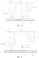
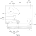
- FIGS. 3-9 show schematic structural diagrams of a repair module in several forms in some embodiments of the present application.
- the supplementary material is slurry
- the repair mechanism 131 includes a storage bin 1311 and a discharge assembly 1312.
- the storage bin 1311 is configured to store the supplementary material
- the discharge assembly 1312 is in communication with the storage bin 1311
- the discharge assembly 1312 is configured to add the supplementary material to the coating defect.
- a spot-shaped coating defect may be formed, the coating defect may have a smaller thickness than other parts of a coating area, or a surface of a current collector may be exposed.
- a supplementary material having a high fluidity may be used to repair the coating defect.
- the storage bin 1311 is mounted on a mounting plate 134, a lower end of the storage bin 1311 is provided with an opening, the discharge assembly 1312 is mounted to the opening and in communication with the storage bin 1311, the supplementary material stored in the storage bin 1311 is discharged from the discharge assembly 1312 under the action of gravity, and the discharge assembly 1312 may be an adhesive spraying nozzle or a adhesive dripping nozzle.
- the discharge assembly 1312 is an adhesive spraying nozzle suitable for repairing a small coating defect where the coating has a smaller thickness.
- the adhesive spraying nozzle sprays a supplementary material in a slurry state to the coating defect, and is applicable to a coating defect where the coating has an insufficient thickness.
- the discharge assembly 1312 is an adhesive dripping nozzle suitable for repairing a small coating defect where a surface of a current collector is exposed.
- the adhesive dripping nozzle adds a drop-shaped supplementary material in a slurry form to the coating defect, and is applicable to a coating defect where no coating exists and the surface of the current collector is exposed.
- the supplementary material in a slurry form is added to the coating defect, and flow of the supplementary material is promoted through rolling, scraping, etc., such that the supplementary material fills the coating defect, and a surface of the supplementary material is flush with the coating area.
- the supplementary material is a strip-shaped material
- the repair mechanism 131 includes an unwinding assembly 1313 and a cutting assembly 1314.
- the unwinding assembly 1313 is configured to unwind the supplementary material
- the cutting assembly 1314 is configured to cut the supplementary material, so as to form a supplementary segment.
- a coating defect usually extends in a preset direction A and has an elongated shape.
- the mounting plate 134 includes a first mounting part 1341 and a second mounting part 1342.
- the first mounting part 1341 is connected to the execution end of the transfer module 120, and the second mounting part 1342 is configured to mount the repair module 130.
- the unwinding assembly 1313 includes an unwinding part 13131 and a number of tension rollers 13132, and the cutting assembly 1314 includes a clamping part 13141, a pulling part 13142 and a cutter 13143.
- the unwinding part 13131, the tension rollers 13132, the clamping part 13141, the pulling part 13142 and the cutter 13143 are all mounted on the second mounting part 1342, the unwinding part 13131 is configured to store a supplementary material in the form of a roll, and the pulling part 13142 is configured to clamp an end portion of the supplementary material in the form of a roll so as to unwind the supplementary material in the form of a roll.
- the tension rollers 13132 are arranged between the unwinding part 13131 and the clamping part 13141, so as to tension the supplementary material in the form of a roll.
- the clamping part 13141 is configured to clamp the supplementary material in the form of a roll, so as to tension the supplementary material to be cut together with the pulling part 13142.
- the cutter 13143 is arranged between the clamping part 13141 and the pulling part 13142, the cutter 13143 can cut off the supplementary material, and a segment between the cutter 13143 and the pulling part 13142 forms a supplementary segment.
- the clamping part 13141 is a pair of clamping jaws for clamping the supplementary material from two sides in a thickness direction of the supplementary material.
- the pulling part 13142 includes a retractable driving member and pulling clamping jaws.
- the retractable driving member is mounted on the second mounting part 1342, the pulling clamping jaws are arranged at an execution end of the retractable driving member, and the retractable driving member can drive the pulling clamping jaws to move in a direction opposite to the preset direction A, so as to unwind the supplementary material under the drive of the pulling clamping jaws.
- the strip-shaped supplementary material is added to the coating defect, and the supplementary material is pressed into the coating defect by means of flattening, etc., so as to fill the coating defect, and a surface of the supplementary material is flush with the coating area.
- the leveling mechanism 132 includes a flattening roller 1321.
- the leveling mechanism 132 includes a scraper 1322.
- the leveling mechanism 132 includes a flattening member 1324 and a flattening driving member 1323.
- the flattening driving member 1323 is configured to drive the flattening member 1324 to move in a thickness direction of the strip 200, so as to flatten the supplementary material added to the coating defect.
- leveling mechanism 132 may have different specific structures.
- the leveling mechanism 132 includes a flattening roller 1321.
- the flattening roller 1321 is mounted on the mounting plate 134, a rotation axis of the flattening roller is parallel to a width direction of the strip 200, and a surface of the flattening roller 1321 is attached to a surface of a coating area of the strip 200, such that the supplementary material protruding from the surface of the strip 200 is rolled to be flush with the surface of the coating area.
- the leveling mechanism 132 includes a scraper 1322.
- the scraper 1322 is mounted on the mounting plate 134, a length direction of the scraper 1322 extends in a width direction of the strip 200, and an end portion of the scraper 1322 is attached to a surface of a coating area of the strip 200, such that the supplementary material protruding from the surface of the strip 200 is scraped off, and the supplementary material is flush with the surface of the coating area.
- the leveling mechanism 132 includes a flattening member 1324 and a flattening driving member 1323.
- the flattening driving member 1323 is configured to drive the flattening member 1324 to move in a thickness direction B of the strip 200, so as to flatten the supplementary material added to the coating defect.
- a supplementary segment may be added to the coating defect, and the supplementary material is pressed, such that the supplementary segment fills the coating defect and is flush with the surface of the coating area, which is suitable for repairing an elongated coating defect.
- Repair mechanisms 131 of various forms and leveling mechanisms 132 of various forms may be combined to form repair modules 130 of various forms.
- the leveling mechanism 132 may include a flattening roller 1321 or a scraper 1322.
- the repair mechanism 131 discharges the supplementary material in a slurry form, and the flattening roller 1321 or the scraper 1322 is used to flatten the supplementary material, such that the supplementary segment fills the coating defect and is flush with the surface of the coating area.
- the leveling mechanism 132 may include a flattening member 1324 and a flattening driving member 1323.
- the repair mechanism 131 forms a supplementary segment through cutting, the supplementary segment falls to the coating defect, and the flattening member 1324 approaches the surface of the strip 200 in the thickness direction B of the strip 200, so as to flatten the supplementary material, such that the supplementary segment fills the coating defect and is flush with the surface of the coating area.
- the leveling mechanism 132 may include a flattening roller 1321 or a scraper (not shown in the figure).
- the repair mechanism 131 forms a supplementary segment through cutting, the supplementary segment falls to the coating defect, and the flattening roller 1321 or the scraper (not shown in the figure) presses the supplementary segment into the coating defect, such that the supplementary segment fills the coating defect and is flush with the surface of the coating area.
- the leveling mechanism 132 includes a flattening member 1324 and a flattening driving member 1323.
- the repair mechanism 131 discharges the supplementary material in a slurry form, and the flattening member 1324 approaches the surface of the strip 200 in the thickness direction B of the strip 200, so as to flatten the supplementary material, such that the supplementary segment fills the coating defect and is flush with the surface of the coating area.
- the leveling mechanism 132 of the foregoing structure has a simple structure, and can level the supplementary material added to the coating defect, such that the supplementary material can fill the coating defect and be flush with the surface of the strip 200.
- the repair module 130 further includes a drying mechanism 133 that is configured to dry the supplementary material added to the coating defect.
- the drying mechanism 133 may be mounted on a mounting plate 134 and located on the side close to the strip 200. Alternatively, the drying mechanism 133 may be separately fixedly arranged and does not move along with the mounting plate 134.
- the drying mechanism 133 can heat the supplementary material after the supplementary material is added to the coating defect, such that the supplementary material completely matches an outline shape of the coating defect, and the supplementary material is integrated with a coating material around the coating defect after fully filling the coating defect and being heated and dried.
- the drying mechanism 133 includes a heat gun or an infrared lamp.
- the drying mechanism 133 may include both the heat gun and the infrared lamp, so as to improve the drying efficiency.
- the drying mechanism 133 may include other forms of heating elements, such as a heating wire.
- the drying mechanism 133 of the foregoing structure has a simple structure and low costs, and can dry the supplementary material added to the coating defect.
- the repair mechanism 131, the leveling mechanism 132 and the drying mechanism 133 are arranged in sequence in the preset direction A.
- the coating defect passes through the repair mechanism 131, the leveling mechanism 132 and the drying mechanism 133 in sequence while the strip 200 travels in the preset direction A, the repair mechanism 131 adds the supplementary material to the coating defect, the leveling mechanism 132 levels the supplementary material added to the coating defect, and then the drying mechanism 133 heats the supplementary material, such that the supplementary material fully fills the coating defect, and the surface of the supplementary material is flush with the surface of the coating area.
- the coating defect of the strip 200 may stop when traveling to a repair position, and the coating defect is repaired in a static state.
- the leveling mechanism 132 further includes a leveling driving member 1325.
- the leveling driving member 1325 is mounted on the mounting plate 134, the flattening driving member 1323 is mounted to an execution end of the leveling driving member 1325, and the flattening member 1324 is mounted to an execution end of the flattening driving member 1323.
- the leveling driving member 1325 can drive the flattening driving member 1323 to move in the preset direction A, such that the flattening member 1324 has a flattening position where it can cover the coating defect and a retracted position where it is clear of a path for the repair mechanism 131 to add the supplementary material to the coating defect.
- the strip 200 travels in the preset direction A, when the repair module 130 reaches a position of the coating defect, the strip 200 stops traveling, the repair mechanism 131 adds the supplementary material to the coating defect, the leveling driving member 1325 drives the flattening driving member 1323 and the flattening member 1324 to move to the flattening position, and the flattening driving member 1323 further drives the flattening member 1324 to approach the surface of the strip 200 in the thickness direction B of the strip 200 until the flattening member is flush with the surface of the coating area of the strip 200, such that the supplementary material fills the coating defect and is flush with the surface of the coating area of the strip 200.
- the coating defect passes through the repair mechanism 131, the leveling mechanism 132 and the drying mechanism 133 in sequence while the strip 200 travels, such that the coating defect of the strip 200 may be repaired while the strip travels at a low speed, and the repair efficiency and the cycle time are improved.
- FIG. 10 shows a schematic structural diagram of a front view of a coating defect repair device in a second form in some embodiments of the present application.
- the strip defect repair device 100 further includes a second detection module 140.
- the second detection module 140 is located upstream of the first detection module 110 and the repair module 130, and the second detection module 140 is configured to detect a coating defect of the strip 200 and transmit an area signal corresponding to the coating defect.
- the transfer module 120 is configured to respond to the area signal and drive the repair module 130 to move to an area corresponding to the coating defect, and then respond to the position signal and drive the repair module 130 to move to the position corresponding to the coating defect.
- the second detection module 140 may be a CCD camera, which detects a color difference to identify whether a coating area has a coating defect.
- the second detection module 140 may be a distance measuring sensor, which detects a coating thickness to identify whether the strip 200 has a coating defect.
- the second detection module 140 may have a lower detection accuracy than the first detection module 110, so as to reduce the cost.
- the second detection module 140 may have the same detection accuracy as the first detection module 110, so as to improve the detection accuracy of the second detection module 140.
- the second detection module 140 is arranged between the unwinding module 150 and the first detection module 110, the second detection module 140 detects the coating defect of the strip 200 before the first detection module 110 and transmits the corresponding area signal, such that the repair module 130 can move to the corresponding area in advance.
- the first detection module 110 further performs detection and transmits the position signal corresponding to the coating defect, and the repair module 130 further moves in a small range so as to accurately reach the position corresponding to the coating defect.
- the second detection module 140 is arranged upstream of the first detection module 110 and the repair module 130, such that the transfer module 120 can drive the repair module 130 to move in advance, so that the repair module 130 can move to the repair position when the coating defect of the strip 200 reaches the repair position, and the repair efficiency and the cycle time of the coating defect can be improved.
- the first detection module 110 is further configured to detect whether the repaired coating defect is acceptable after the repair module 130 finishes repairing.
- the strip defect repair device 100 further includes a marking module 170.
- the marking module 170 is located downstream of the repair module 130, and the marking module 170 is configured to mark the strip 200 when the first detection module 110 detects that the repaired coating defect is unacceptable.
- the marking module 170 bonds an adhesive tape or paper that has a different color from the current collector and the coating area of the strip 200 to the surface of the strip 200, and an edge of the adhesive tape or paper extends beyond an edge of the strip 200, such that a worker can identify the strip 200 having an unsuccessfully repaired coating defect.
- the marking module 170 may mark the surface of the strip 200 with other markers, such as magnetic materials or radioactive materials, so as to cooperate with a corresponding detection module to identify the unsuccessfully repaired strip 200.
- the strip 200 after defect repairing is directly marked and wound up.
- the strip 200 after defect repairing may be slitted first, and then marked and wound up.
- FIG. 11 shows a schematic structural diagram of a front view of a coating defect repair device in a third form in some embodiments of the present application.
- the strip defect repair device 100 further includes a slitting module 180.
- the slitting module 180 is arranged behind the repair module 130 and is configured to slit the strip 200 after defect repairing, so as to form two sub-strips 210, and each sub-strip 210 corresponds to a marking module 170 and a winding module 160.
- the first detection module 110 may be used to detect whether the defect repairing is acceptable, and to further determine which one of the sub-strips 210 formed after slitting has an unsuccessfully repaired coating defect or that the two sub-strips 210 each have an unsuccessfully repaired coating defect, the sub-strip 210 having an unsuccessfully repaired coating defect is marked, and the sub-strip 210 having no coating defect or having a successfully repaired coating defect is wound up and unloaded as an acceptable sub-strip 210.
- some embodiments of the present application provide a strip defect repair device 100 including an unwinding module 150, a second detection module 140, a repair station, a slitting module 180 and two winding sub-modules formed after slitting, which are arranged in sequence in the preset direction A.
- Each winding sub-module includes a marking module 170 and a winding module 160.
- the repair station includes a first detection module 110, a transfer module 120, and a repair module 130. When an electrode plate strip passes through the repair station, a coating defect may be repaired and whether the repaired coating defect is acceptable may be detected.
- the electrode plate strip is unwound by the unwinding module 150, and a coating defect may exist on the electrode plate strip.
- the second detection module 140 detects the existence of a coating defect through color difference comparison, and detects an area corresponding to the coating defect.
- the transfer module 120 responds and moves the repair module 130 to the area corresponding to the time when the coating defect reaches the repair station.
- the first detection module 110 detects a position corresponding to the coating defect through color difference comparison, and the transfer module 120 responds and moves the repair module 130 to an accurate position of the coating defect.
- the electrode plate strip continues to travel to pass through a repair mechanism 131, a leveling mechanism 132 and a drying mechanism 133 in sequence.
- the repair mechanism 131 adds a supplementary material to the coating defect, the leveling mechanism 132 levels the supplementary material, and the drying mechanism 133 heats the supplementary material, so as to complete the repairing of the coating defect.
- the first detection module 110 detects whether a color difference ratio between the repaired coating defect and other areas of the coating area is smaller than a preset value through color difference comparison again, and determines whether the coating defect is successfully repaired at the repair station. If the color difference ratio is greater than the preset value, it is determined that the coating defect is unsuccessfully repaired, and the unsuccessfully repaired coating defect belongs to one or both of the sub-strips 210 is determined.
- the marking module 170 bonds a marking bar to the sub-strip 210 having an unsuccessfully repaired coating defect, and an end portion of the marking bar is exposed from an edge of the sub-strip 210 in the width direction.
- the winding modules 160 wind up the two sub-strips 210, and whether the sub-strips 210 have the color of the marking bar is detected by the worker or through intelligent identification. If a sub-strip 210 is bonded with a marking bar, it can be determined that the sub-strip 210 is a waste material and needs to be scrapped. The sub-strip 210 having no marking bar is discharged as an acceptable strip.
- the strip defect repair device 100 provided in the embodiments of the present application may be used to repair the coating defect already formed, detect a repair result, and then perform slitting, such that a scrap rate of the electrode plate strip is effectively reduced, the manufacturing cost of the acceptable electrode plate strip is decreased, and the manufacturing cost of the electrode assembly and the battery cell is thus decreased.
Landscapes
- Engineering & Computer Science (AREA)
- Manufacturing & Machinery (AREA)
- Chemical & Material Sciences (AREA)
- Chemical Kinetics & Catalysis (AREA)
- Electrochemistry (AREA)
- General Chemical & Material Sciences (AREA)
- Battery Electrode And Active Subsutance (AREA)
Abstract
Description
- The present application claims the priority to
Chinese patent application no. 202122034740.5, filed on August 26, 2021 - The present application relates to the technical field of battery manufacturing, and in particular, to a strip defect repair device.
- As the new energy vehicle industry is booming, the demand for batteries is rising rapidly, and the consumption of raw materials for batteries is also increasing, so it is very important to reduce cost of the raw materials for batteries.
- An electrode plate strip is an important raw material for forming an electrode assembly of a battery. A coating area of the electrode plate strip may have a coating defect. A short circuit may occur in the electrode assembly made of the electrode plate strip having a coating defect, affecting the safety performance of the battery. At present, the electrode plate strip having a coating defect is discarded, resulting in high manufacturing costs of both acceptable electrode plate strips and batteries.
- In view of this, the present application provides a strip defect repair device, which can repair a strip coating defect already formed on the strip, reduce a scrap rate of the strip, and thus decrease the manufacturing cost of acceptable strips.
- Some embodiments of the present application provide a strip defect repair device configured to repair a coating defect of a strip, the strip defect repair device including: a first detection module configured to detect the coating defect of the strip and feed back a position signal corresponding to the coating defect; a transfer module; and a repair module, wherein the transfer module is configured to respond to the position signal and drive the repair module to move to a position corresponding to the coating defect, and the repair module is configured to add a supplementary material to the coating defect so as to repair the coating defect.
- The first detection module detects whether the strip has a coating defect and feeds back the position signal corresponding to the coating defect, the transfer module drives the repair module to move to the position corresponding to the coating defect, and the repair module adds the supplementary material to the coating defect at a position where the coating defect is located, so as to repair the coating defect, such that a scrap rate of the strip can be reduced, and then manufacturing cost of a product using the strip as a raw material can be decreased. When the strip is an electrode plate strip, a coating defect repair device in the embodiments of the present application may be used to repair a coating defect already formed on the electrode plate strip, so as to reduce a scrap rate of the electrode plate strip, and decrease the manufacturing cost of both acceptable strips and battery cells.
- According to some embodiments of the present application, the repair module includes: a repair mechanism configured to add the supplementary material to the coating defect; and a leveling mechanism configured to level the supplementary material added to the coating defect.
- The repair mechanism is used to add the supplementary material to the coating defect, and the leveling mechanism is used to level the supplementary material added to the coating defect, such that the supplementary material can fill the coating defect and be flush with a surface of the strip.
- According to some embodiments of the present application, the supplementary material is slurry, and the repair mechanism includes: a storage bin configured to store the supplementary material; and a discharge assembly, wherein the discharge assembly is in communication with the storage bin, and the discharge assembly is configured to add the supplementary material to the coating defect.
- By means of the foregoing structure, the supplementary material in a slurry state can be added to the coating defect, which is suitable for repairing a small coating defect, or a coating defect where the coating has a smaller thickness, or a coating defect where no coating is applied.
- According to some embodiments of the present application, the supplementary material is a strip-shaped material, and the repair mechanism includes: an unwinding assembly configured to unwind the supplementary material; and a cutting assembly configured to cut the supplementary material, so as to form a supplementary segment.
- By means of the foregoing structure, the supplementary material in the form of the strip-shaped material can be added to the coating defect, which is suitable for repairing an elongated coating defect.
- According to some embodiments of the present application, the leveling mechanism includes a flattening roller; or
- the leveling mechanism comprises a scraper; or
- the leveling mechanism includes a flattening member and a flattening driving member, the flattening driving member being configured to drive the flattening member to move in a thickness direction of the strip, so as to flatten the supplementary material added to the coating defect.
- The leveling mechanism of the foregoing structure has a simple structure, and can level the supplementary material added to the coating defect, such that the supplementary material can fill the coating defect and be flush with the surface of the strip.
- According to some embodiments of the present application, the repair module further includes: a drying mechanism configured to dry the supplementary material added to the coating defect.
- The drying mechanism can heat the supplementary material after the supplementary material is added to the coating defect, such that the supplementary material fully supplements an outline shape of the coating defect, and the supplementary material is integrated with a coating material around the coating defect after fully filling the coating defect and being heated and dried.
- According to some embodiments of the present application, the drying mechanism includes a heat gun and/or an infrared lamp, so that the drying mechanism has a simple structure and low costs, and can dry the supplementary material added to the coating defect.
- According to some embodiments of the present application, the repair mechanism, the leveling mechanism and the drying mechanism are arranged in sequence in a traveling direction of the strip.
- By means of the foregoing structure, the coating defect can be repaired, leveled and dried in sequence while the strip is traveling, such that the defect repair efficiency and the cycle time are improved.
- According to some embodiments of the present application, the strip defect repair device further includes: a second detection module located upstream of the first detection module and the repair module, wherein the second detection module is configured to detect the coating defect of the strip and transmit an area signal corresponding to the coating defect; and the transfer module is configured to respond to the area signal and drive the repair module to move to an area corresponding to the coating defect, and then respond to the position signal and drive the repair module to move to the position corresponding to the coating defect.
- The second detection module is used to detect the coating defect of the strip and transmit the corresponding area signal, such that the repair module may move to the corresponding area in advance. When the traveling of the strip drives the coating defect to move in place, the first detection module further performs detection and transmits the position signal corresponding to the coating defect, and the repair module further moves in a small range so as to accurately reach the position corresponding to the coating defect. In this way, the transfer module can drive the repair module to move in advance, such that the repair module reaches a repair position at the same time when the coating defect of the strip reaches the repair position, and the repair efficiency and the cycle time of the coating defect can be improved.
- According to some embodiments of the present application, the first detection module is further configured to detect whether the repaired coating defect is acceptable; and the strip defect repair device further includes a marking module located downstream of the repair module and configured to mark the strip when the first detection module detects that the repaired coating defect is unacceptable.
- After the coating defect is repaired, whether the repaired coating defect is acceptable is detected again, and the unacceptable repaired coating defect is marked, so that whether the coating defect is repaired successfully can be further detected, and the strip having an unsuccessfully repaired coating defect is identified for scrapping.
- Some of the additional aspects and advantages of the present application will be set forth in the following description, and some will become apparent from the following description, or be learned by practice of the present application.
- In order to more clearly describe the technical solutions of the embodiments of the present application, the accompanying drawings required in the embodiments will be described briefly below. It should be understood that the following accompanying drawings illustrate only some embodiments of the present application and therefore should not be construed as a limitation on the scope thereof. For those of ordinary skill in the art, other relevant accompanying drawings can also be obtained from these accompanying drawings without any creative effort.
-
FIG. 1 shows a schematic structural diagram of a front view of a strip defect repair device in a first form in some embodiments of the present application; -
FIG. 2 shows a schematic structural diagram of a top view of a coating defect repair device in some embodiments of the present application; -
FIG. 3 shows a schematic structural diagram of a repair module in a first form in some embodiments of the present application; -
FIG. 4 shows a schematic structural diagram of a repair module in a second form in some embodiments of the present application; -
FIGS. 5 and6 show schematic structural diagrams of a repair module in a third form in two states in some embodiments of the present application, respectively; -
FIG. 7 shows a schematic structural diagram of a repair module in a fourth form in some embodiments of the present application; -
FIG. 8 shows a schematic structural diagram of a repair module in a fifth form in some embodiments of the present application; -
FIG. 9 shows a schematic structural diagram of a repair module in a sixth form in some embodiments of the present application; -
FIG. 10 shows a schematic structural diagram of a front view of a coating defect repair device in a second form in some embodiments of the present application; and -
FIG. 11 shows a schematic structural diagram of a front view of a coating defect repair device in a third form in some embodiments of the present application. - The foregoing drawings are not drawn to scale.
- List of reference signs: 100 - Strip defect repair device; 110 - First detection module; 120 - Transfer module; 130 - Repair module; 131 - Repair mechanism; 1311 - Storage bin; 1312 - Discharge assembly; 1313 - Unwinding assembly; 13131 - Unwinding part; 13132 - Tension roller; 1314 - Cutting assembly; 13141 - Clamping part; 13142 - Pulling part; 13143 - Cutter; 132 - Leveling mechanism; 1321 - Flattening roller; 1322 - Scraper; 1323 - Flattening driving member; 1324 - Flattening member; 1325 - Leveling driving member; 133 - Drying mechanism; 134 - Mounting plate; 1341 - First mounting part; 1342 - Second mounting part; 140 - Second detection module; 150 - Unwinding module; 160 - Winding module; 170 - Marking module; 180 - Slitting module; 200 - Strip; 210 - Sub-strip.
- In order to make the objectives, technical solutions and advantages of the embodiments of the present application clearer, the technical solutions in the embodiments of the present application will be described clearly below with reference to the drawings in the embodiments of the present application. Obviously, the embodiments described are some of, rather than all of, the embodiments of the present application. All the other embodiments obtained by those of ordinary skill in the art based on the embodiments of the present application without creative efforts shall fall within the scope of protection of the present application.
- Unless otherwise defined, all technical and scientific terms used in the present application have the same meanings as those commonly understood by those skilled in the art to which the present application belongs. The terms used in the description of the present application are merely for the purpose of describing specific embodiments, but are not intended to limit the present application. The terms "comprising/including", "provided with", and any variations thereof in the description and claims, as well as the brief description of the drawings described above of the present application are intended to cover non-exclusive inclusions. The terms "first", "second", etc. in the description and the claims of the present application as well as the foregoing drawings are used to distinguish between different objects, rather than describing a specific order or a primary-secondary relationship.
- In the present application, the phrase "embodiment" mentioned means that the specific features, structures, or characteristics described with reference to the embodiments can be encompassed in at least one embodiment of the present application. The phrase at various positions in the description does not necessarily refer to the same embodiment, or an independent or alternative embodiment exclusive of another embodiment. Those skilled in the art should understand, in explicit and implicit manners, that an embodiment described in the present application may be combined with another embodiment.
- In the description of the present application, it should be noted that, the terms "mount", "connected", "connect", or "attach" should be interpreted in a broad sense unless explicitly defined and limited otherwise. For example, they may be a fixed connection, a detachable connection, or an integral connection; or may be a direct connection, an indirect connection by means of an intermediate medium, or internal communication between two elements. For those of ordinary skills in the art, the specific meaning of the foregoing terms in the present application can be understood according to specific circumstances.
- The phrase "a plurality of' appearing in the present application means two or more (including two).
- In the present application, a battery cell may include a lithium ion secondary battery, a lithium ion primary battery, a lithium-sulfur battery, a sodium-lithium ion battery, a sodium ion battery, a magnesium ion battery, etc., which will not be limited in the embodiments of the present application. The battery cell may be cylindrical, flat, cuboid or in another shape, which will also not be limited in the embodiments of the present application. The battery cells are generally classified into three types depending on the way of package: cylindrical battery cells, prismatic battery cells and pouch battery cells.
- The battery cell includes an electrode assembly and an electrolyte. The electrode assembly is composed of a positive electrode plate, a negative electrode plate and a separator. The battery cell operates mainly by relying on movements of metal ions between the positive electrode plate and the negative electrode plate. The positive electrode plate includes a positive electrode current collector and a positive electrode active material layer. A surface of the positive electrode current collector is coated with the positive electrode active material layer, the positive electrode current collector not coated with the positive electrode active material layer protrudes from the positive electrode current collector coated with the positive electrode active material layer, and the positive electrode current collector not coated with the positive electrode active material layer serves as a positive tab. Taking a lithium ion battery as an example, the positive electrode current collector may be made of aluminum, and the positive electrode active material may be lithium cobalt oxide, lithium iron phosphate, ternary lithium, lithium manganate, etc. The negative electrode plate comprises a negative electrode current collector and a negative electrode active material layer. A surface of the negative electrode current collector is coated with the negative electrode active material layer, the negative electrode current collector that is not coated with the negative electrode active material layer protrudes from the negative electrode current collector coated with the negative electrode active material layer, and the negative electrode current collector that is not coated with the negative electrode active material layer is used as a negative electrode tab. The negative electrode current collector may be made of copper, and the negative electrode active material may be carbon, silicon, etc. In order to ensure that no fusing occurs when a large current passes, there are a plurality of positive electrode tabs which are stacked together, and there are a plurality of negative electrode tabs which are stacked together. The separator may be made of polypropylene (PP), polyethylene (PE), etc. In addition, the electrode assembly may be of a wound structure or a laminated structure, which will not be limited in the embodiments of the present application.
- In a manufacturing process of an electrode plate strip, it is necessary to coat a surface of a current collector with an active material to form a coating area, and then to form the electrode plate strip having the coating area through cold pressing and drying. The inventors have found that bubbles mixed in the active material, foreign matter on a surface of a pressing roller during cold pressing and an improper drying temperature during drying may all lead to an insufficient coating thickness or no active material coverage of part of the coating area, resulting in a coating defect. If the electrode plate strip having a coating defect is used to form an electrode assembly, a positive electrode current collector of the electrode assembly may come into contact with a negative electrode current collector, resulting in short circuit occurring in a battery cell. At present, electrode plate strips having coating defects are mainly scrapped, such that losses of material costs and equipment productivity are caused, and the production cost of electrode plate strips is increased.
- Based on the foregoing solution, the present application provides a coating defect repair device, which can detect a coating defect of an electrode plate strip and repair the coating defect already formed. A successfully repaired electrode plate strip may be used as an acceptable strip, such that a scrap rate of the electrode plate strip is reduced, and the manufacturing cost of the acceptable strip and therefore of the electrode assembly and the battery cell is decreased.
-
FIG. 1 shows a schematic structural diagram of a front view of a strip defect repair device in a first form in some embodiments of the present application. - As shown in
FIG. 1 , a stripdefect repair device 100 includes an unwindingmodule 150 and a windingmodule 160, astrip 200 travels in a preset direction A, two ends of thestrip 200 are connected to the unwindingmodule 150 and the windingmodule 160 respectively, the unwindingmodule 150 is configured to unwind thestrip 200 to be subjected to coating defect detection and defect repairing, and the windingmodule 160 is configured to wind up thestrip 200 after defect repairing. - The strip
defect repair device 100 includes afirst detection module 110, atransfer module 120 and arepair module 130. Thefirst detection module 110 is configured to detect a coating defect of thestrip 200 and feed back a position signal corresponding to the coating defect, thetransfer module 120 is configured to respond to the position signal and drive therepair module 130 to move to a position corresponding to the coating defect, and therepair module 130 is configured to add a supplementary material to the coating defect so as to repair the coating defect. - It may be understood that a coating defect of an electrode plate strip means that a coating area has a local coating thickness smaller than a normal thickness; or a coating area is locally coated with no active material such that a current collector is exposed; or two connected electrode plate strips are bonded by an adhesive tape, and a connection gap exists at a joint of the two electrode plate strips.
- The
strip 200 to which the stripdefect repair device 100 is applicable may be an electrode plate strip for forming an electrode assembly, or other types of strips, which will not be further limited herein. - The supplementary material may have the same material as the coating area. A coating material is added to the coating defect, so as to repair the coating defect. Alternatively, the supplementary material may have a different material from the coating area. The supplementary material is an insulation adhesive, so as to prevent the current collector from being exposed and short-circuited with an electrode plate of the other polarity after the electrode assembly is formed.
- The
first detection module 110 may be configured to detect the coating defect of thestrip 200 and feed back the position signal corresponding to the coating defect, and to further detect whether the repaired coating defect is acceptable while detecting whether thestrip 200 has a coating defect. Thefirst detection module 110 may be a charge coupled device (CCD) camera, which detects a color difference to identify whether thestrip 200 has a coating defect. Alternatively, thefirst detection module 110 may be a distance measuring sensor, which detects a coating thickness to identify whether thestrip 200 has a coating defect. - The
transfer module 120 may be a three-line driving mechanism or a six-axis manipulator. Thetransfer module 120 may respond to a detection result of thefirst detection module 110 and drive therepair module 130 to reach the position corresponding to the coating defect, or may reach an area corresponding to the coating defect before responding to thefirst detection module 110, so that the repair efficiency of the coating defect is improved. - The
first detection module 110 detects whether the strip has a coating defect and feeds back the position signal corresponding to the coating defect, thetransfer module 120 drives therepair module 130 to move to the position corresponding to the coating defect, and therepair module 130 adds the supplementary material to the coating defect at a position where the coating defect is located, so as to repair the coating defect, such that a scrap rate of thestrip 200 can be reduced, and then manufacturing cost of the electrode assembly and the battery cell can be decreased. -
FIG. 2 shows a schematic structural diagram of a top view of a coating defect repair device in some embodiments of the present application. - As shown in
FIG. 2 , therepair module 130 includes arepair mechanism 131 and aleveling mechanism 132. Therepair mechanism 131 is configured to add a supplementary material to the coating defect, and theleveling mechanism 132 is configured to level the supplementary material added to the coating defect. - Specifically, the
repair module 130 further includes a mountingplate 134. The mountingplate 134 is mounted on an execution end of atransfer module 120, and therepair mechanism 131 and theleveling mechanism 132 are both mounted on the mountingplate 134. - The
repair module 130 may repair a spot-shaped or elongated coating defect. For different types of coating defects, therepair mechanism 131 and theleveling mechanism 132 may have different structures. - The
repair mechanism 131 is used to add the supplementary material to the coating defect, and theleveling mechanism 132 is used to level the supplementary material added to the coating defect, such that the supplementary material fills the coating defect and is flush with a surface of thestrip 200. -
FIGS. 3-9 show schematic structural diagrams of a repair module in several forms in some embodiments of the present application. - As shown in
FIGS. 3 and 4 , in some embodiments of the present application, the supplementary material is slurry, and therepair mechanism 131 includes astorage bin 1311 and adischarge assembly 1312. Thestorage bin 1311 is configured to store the supplementary material, thedischarge assembly 1312 is in communication with thestorage bin 1311, and thedischarge assembly 1312 is configured to add the supplementary material to the coating defect. - It may be understood that in a coating process of an active material, if bubbles are mixed in the active material, a spot-shaped coating defect may be formed, the coating defect may have a smaller thickness than other parts of a coating area, or a surface of a current collector may be exposed. For this type of coating defect, a supplementary material having a high fluidity may be used to repair the coating defect.
- Specifically, the
storage bin 1311 is mounted on a mountingplate 134, a lower end of thestorage bin 1311 is provided with an opening, thedischarge assembly 1312 is mounted to the opening and in communication with thestorage bin 1311, the supplementary material stored in thestorage bin 1311 is discharged from thedischarge assembly 1312 under the action of gravity, and thedischarge assembly 1312 may be an adhesive spraying nozzle or a adhesive dripping nozzle. - As shown in
FIG. 3 , thedischarge assembly 1312 is an adhesive spraying nozzle suitable for repairing a small coating defect where the coating has a smaller thickness. The adhesive spraying nozzle sprays a supplementary material in a slurry state to the coating defect, and is applicable to a coating defect where the coating has an insufficient thickness. - As shown in
FIG. 4 , thedischarge assembly 1312 is an adhesive dripping nozzle suitable for repairing a small coating defect where a surface of a current collector is exposed. The adhesive dripping nozzle adds a drop-shaped supplementary material in a slurry form to the coating defect, and is applicable to a coating defect where no coating exists and the surface of the current collector is exposed. - The supplementary material in a slurry form is added to the coating defect, and flow of the supplementary material is promoted through rolling, scraping, etc., such that the supplementary material fills the coating defect, and a surface of the supplementary material is flush with the coating area.
- As shown in
FIGS. 5 and6 , in some embodiments of the present application, the supplementary material is a strip-shaped material, and therepair mechanism 131 includes an unwindingassembly 1313 and acutting assembly 1314. The unwindingassembly 1313 is configured to unwind the supplementary material, and the cuttingassembly 1314 is configured to cut the supplementary material, so as to form a supplementary segment. - It may be understood that foreign matter on a surface of a roller during cold pressing and an improper drying temperature may both lead to an insufficient coating thickness or no active material coverage of part of a coating area, and a coating defect usually extends in a preset direction A and has an elongated shape.
- Specifically, the mounting
plate 134 includes a first mountingpart 1341 and asecond mounting part 1342. Thefirst mounting part 1341 is connected to the execution end of thetransfer module 120, and the second mountingpart 1342 is configured to mount therepair module 130. The unwindingassembly 1313 includes an unwindingpart 13131 and a number oftension rollers 13132, and the cuttingassembly 1314 includes a clampingpart 13141, a pullingpart 13142 and acutter 13143. The unwindingpart 13131, thetension rollers 13132, the clampingpart 13141, the pullingpart 13142 and thecutter 13143 are all mounted on the second mountingpart 1342, the unwindingpart 13131 is configured to store a supplementary material in the form of a roll, and the pullingpart 13142 is configured to clamp an end portion of the supplementary material in the form of a roll so as to unwind the supplementary material in the form of a roll. Thetension rollers 13132 are arranged between the unwindingpart 13131 and the clampingpart 13141, so as to tension the supplementary material in the form of a roll. The clampingpart 13141 is configured to clamp the supplementary material in the form of a roll, so as to tension the supplementary material to be cut together with the pullingpart 13142. Thecutter 13143 is arranged between the clampingpart 13141 and the pullingpart 13142, thecutter 13143 can cut off the supplementary material, and a segment between thecutter 13143 and the pullingpart 13142 forms a supplementary segment. - The clamping
part 13141 is a pair of clamping jaws for clamping the supplementary material from two sides in a thickness direction of the supplementary material. - The pulling
part 13142 includes a retractable driving member and pulling clamping jaws. The retractable driving member is mounted on the second mountingpart 1342, the pulling clamping jaws are arranged at an execution end of the retractable driving member, and the retractable driving member can drive the pulling clamping jaws to move in a direction opposite to the preset direction A, so as to unwind the supplementary material under the drive of the pulling clamping jaws. - The strip-shaped supplementary material is added to the coating defect, and the supplementary material is pressed into the coating defect by means of flattening, etc., so as to fill the coating defect, and a surface of the supplementary material is flush with the coating area.
- As shown in
FIGS. 3, 4 ,5 and6 , in some embodiments of the present application, theleveling mechanism 132 includes a flatteningroller 1321. Alternatively, theleveling mechanism 132 includes ascraper 1322. Alternatively, theleveling mechanism 132 includes a flatteningmember 1324 and aflattening driving member 1323. Theflattening driving member 1323 is configured to drive the flatteningmember 1324 to move in a thickness direction of thestrip 200, so as to flatten the supplementary material added to the coating defect. - It may be understood that the
leveling mechanism 132 may have different specific structures. - As shown in
FIG. 3 , theleveling mechanism 132 includes a flatteningroller 1321. The flatteningroller 1321 is mounted on the mountingplate 134, a rotation axis of the flattening roller is parallel to a width direction of thestrip 200, and a surface of the flatteningroller 1321 is attached to a surface of a coating area of thestrip 200, such that the supplementary material protruding from the surface of thestrip 200 is rolled to be flush with the surface of the coating area. - As shown in
FIG. 4 , theleveling mechanism 132 includes ascraper 1322. Thescraper 1322 is mounted on the mountingplate 134, a length direction of thescraper 1322 extends in a width direction of thestrip 200, and an end portion of thescraper 1322 is attached to a surface of a coating area of thestrip 200, such that the supplementary material protruding from the surface of thestrip 200 is scraped off, and the supplementary material is flush with the surface of the coating area. - As shown in
FIGS. 5 and6 , theleveling mechanism 132 includes a flatteningmember 1324 and aflattening driving member 1323. Theflattening driving member 1323 is configured to drive the flatteningmember 1324 to move in a thickness direction B of thestrip 200, so as to flatten the supplementary material added to the coating defect. By means of the foregoing structure, a supplementary segment may be added to the coating defect, and the supplementary material is pressed, such that the supplementary segment fills the coating defect and is flush with the surface of the coating area, which is suitable for repairing an elongated coating defect. -
Repair mechanisms 131 of various forms and levelingmechanisms 132 of various forms may be combined to formrepair modules 130 of various forms. - As shown in
FIGS. 3 and 4 , for example, in the foregoing embodiment where therepair mechanism 131 includes astorage bin 1311 and adischarge assembly 1312, theleveling mechanism 132 may include a flatteningroller 1321 or ascraper 1322. Therepair mechanism 131 discharges the supplementary material in a slurry form, and the flatteningroller 1321 or thescraper 1322 is used to flatten the supplementary material, such that the supplementary segment fills the coating defect and is flush with the surface of the coating area. - As shown in
FIGS. 5 and6 , for example, in the foregoing embodiment where therepair mechanism 131 includes an unwindingassembly 1313 and acutting assembly 1314, theleveling mechanism 132 may include a flatteningmember 1324 and aflattening driving member 1323. Therepair mechanism 131 forms a supplementary segment through cutting, the supplementary segment falls to the coating defect, and the flatteningmember 1324 approaches the surface of thestrip 200 in the thickness direction B of thestrip 200, so as to flatten the supplementary material, such that the supplementary segment fills the coating defect and is flush with the surface of the coating area. - As shown in
FIG. 7 , for example, in the embodiment where therepair mechanism 131 includes an unwindingassembly 1313 and acutting assembly 1314, theleveling mechanism 132 may include a flatteningroller 1321 or a scraper (not shown in the figure). Therepair mechanism 131 forms a supplementary segment through cutting, the supplementary segment falls to the coating defect, and the flatteningroller 1321 or the scraper (not shown in the figure) presses the supplementary segment into the coating defect, such that the supplementary segment fills the coating defect and is flush with the surface of the coating area. - As shown in
FIG. 8 , for another example, in the embodiment where therepair mechanism 131 includes astorage bin 1311 and adischarge assembly 1312, theleveling mechanism 132 includes a flatteningmember 1324 and aflattening driving member 1323. Therepair mechanism 131 discharges the supplementary material in a slurry form, and the flatteningmember 1324 approaches the surface of thestrip 200 in the thickness direction B of thestrip 200, so as to flatten the supplementary material, such that the supplementary segment fills the coating defect and is flush with the surface of the coating area. - The
leveling mechanism 132 of the foregoing structure has a simple structure, and can level the supplementary material added to the coating defect, such that the supplementary material can fill the coating defect and be flush with the surface of thestrip 200. - As shown in
FIG. 8 , in some embodiments of the present application, therepair module 130 further includes adrying mechanism 133 that is configured to dry the supplementary material added to the coating defect. - The
drying mechanism 133 may be mounted on a mountingplate 134 and located on the side close to thestrip 200. Alternatively, thedrying mechanism 133 may be separately fixedly arranged and does not move along with the mountingplate 134. - The
drying mechanism 133 can heat the supplementary material after the supplementary material is added to the coating defect, such that the supplementary material completely matches an outline shape of the coating defect, and the supplementary material is integrated with a coating material around the coating defect after fully filling the coating defect and being heated and dried. - In some embodiments of the present application, the
drying mechanism 133 includes a heat gun or an infrared lamp. - Specifically, the
drying mechanism 133 may include both the heat gun and the infrared lamp, so as to improve the drying efficiency. Alternatively, thedrying mechanism 133 may include other forms of heating elements, such as a heating wire. - The
drying mechanism 133 of the foregoing structure has a simple structure and low costs, and can dry the supplementary material added to the coating defect. - As shown in
FIG. 8 , in some embodiments of the present application, therepair mechanism 131, theleveling mechanism 132 and thedrying mechanism 133 are arranged in sequence in the preset direction A. - The coating defect passes through the
repair mechanism 131, theleveling mechanism 132 and thedrying mechanism 133 in sequence while thestrip 200 travels in the preset direction A, therepair mechanism 131 adds the supplementary material to the coating defect, theleveling mechanism 132 levels the supplementary material added to the coating defect, and then thedrying mechanism 133 heats the supplementary material, such that the supplementary material fully fills the coating defect, and the surface of the supplementary material is flush with the surface of the coating area. - The coating defect of the
strip 200 may stop when traveling to a repair position, and the coating defect is repaired in a static state. - As shown in
FIG. 9 , theleveling mechanism 132 further includes aleveling driving member 1325. Theleveling driving member 1325 is mounted on the mountingplate 134, theflattening driving member 1323 is mounted to an execution end of theleveling driving member 1325, and the flatteningmember 1324 is mounted to an execution end of theflattening driving member 1323. Theleveling driving member 1325 can drive theflattening driving member 1323 to move in the preset direction A, such that the flatteningmember 1324 has a flattening position where it can cover the coating defect and a retracted position where it is clear of a path for therepair mechanism 131 to add the supplementary material to the coating defect. By means of the foregoing structure, thestrip 200 travels in the preset direction A, when therepair module 130 reaches a position of the coating defect, thestrip 200 stops traveling, therepair mechanism 131 adds the supplementary material to the coating defect, theleveling driving member 1325 drives theflattening driving member 1323 and the flatteningmember 1324 to move to the flattening position, and theflattening driving member 1323 further drives the flatteningmember 1324 to approach the surface of thestrip 200 in the thickness direction B of thestrip 200 until the flattening member is flush with the surface of the coating area of thestrip 200, such that the supplementary material fills the coating defect and is flush with the surface of the coating area of thestrip 200. - In some embodiments of the present application, the coating defect passes through the
repair mechanism 131, theleveling mechanism 132 and thedrying mechanism 133 in sequence while thestrip 200 travels, such that the coating defect of thestrip 200 may be repaired while the strip travels at a low speed, and the repair efficiency and the cycle time are improved. -
FIG. 10 shows a schematic structural diagram of a front view of a coating defect repair device in a second form in some embodiments of the present application. - As shown in
FIG. 10 , in some embodiments of the present application, the stripdefect repair device 100 further includes asecond detection module 140. Thesecond detection module 140 is located upstream of thefirst detection module 110 and therepair module 130, and thesecond detection module 140 is configured to detect a coating defect of thestrip 200 and transmit an area signal corresponding to the coating defect. Thetransfer module 120 is configured to respond to the area signal and drive therepair module 130 to move to an area corresponding to the coating defect, and then respond to the position signal and drive therepair module 130 to move to the position corresponding to the coating defect. - The
second detection module 140 may be a CCD camera, which detects a color difference to identify whether a coating area has a coating defect. Alternatively, thesecond detection module 140 may be a distance measuring sensor, which detects a coating thickness to identify whether thestrip 200 has a coating defect. Thesecond detection module 140 may have a lower detection accuracy than thefirst detection module 110, so as to reduce the cost. Alternatively, thesecond detection module 140 may have the same detection accuracy as thefirst detection module 110, so as to improve the detection accuracy of thesecond detection module 140. - The
second detection module 140 is arranged between the unwindingmodule 150 and thefirst detection module 110, thesecond detection module 140 detects the coating defect of thestrip 200 before thefirst detection module 110 and transmits the corresponding area signal, such that therepair module 130 can move to the corresponding area in advance. When the traveling of thestrip 200 drives the coating defect to move to a repair position, thefirst detection module 110 further performs detection and transmits the position signal corresponding to the coating defect, and therepair module 130 further moves in a small range so as to accurately reach the position corresponding to the coating defect. - The
second detection module 140 is arranged upstream of thefirst detection module 110 and therepair module 130, such that thetransfer module 120 can drive therepair module 130 to move in advance, so that therepair module 130 can move to the repair position when the coating defect of thestrip 200 reaches the repair position, and the repair efficiency and the cycle time of the coating defect can be improved. - As shown in
FIG. 10 , in some embodiments of the present application, thefirst detection module 110 is further configured to detect whether the repaired coating defect is acceptable after therepair module 130 finishes repairing. The stripdefect repair device 100 further includes amarking module 170. The markingmodule 170 is located downstream of therepair module 130, and themarking module 170 is configured to mark thestrip 200 when thefirst detection module 110 detects that the repaired coating defect is unacceptable. - The marking
module 170 bonds an adhesive tape or paper that has a different color from the current collector and the coating area of thestrip 200 to the surface of thestrip 200, and an edge of the adhesive tape or paper extends beyond an edge of thestrip 200, such that a worker can identify thestrip 200 having an unsuccessfully repaired coating defect. Alternatively, the markingmodule 170 may mark the surface of thestrip 200 with other markers, such as magnetic materials or radioactive materials, so as to cooperate with a corresponding detection module to identify the unsuccessfully repairedstrip 200. - The
strip 200 after defect repairing is directly marked and wound up. Alternatively, thestrip 200 after defect repairing may be slitted first, and then marked and wound up. -
FIG. 11 shows a schematic structural diagram of a front view of a coating defect repair device in a third form in some embodiments of the present application. - As shown in
FIG. 11 , the stripdefect repair device 100 further includes aslitting module 180. Theslitting module 180 is arranged behind therepair module 130 and is configured to slit thestrip 200 after defect repairing, so as to form twosub-strips 210, and each sub-strip 210 corresponds to amarking module 170 and a windingmodule 160. By means of the structure, thefirst detection module 110 may be used to detect whether the defect repairing is acceptable, and to further determine which one of the sub-strips 210 formed after slitting has an unsuccessfully repaired coating defect or that the twosub-strips 210 each have an unsuccessfully repaired coating defect, the sub-strip 210 having an unsuccessfully repaired coating defect is marked, and the sub-strip 210 having no coating defect or having a successfully repaired coating defect is wound up and unloaded as anacceptable sub-strip 210. - After the coating defect is repaired, whether the repaired coating defect is acceptable is detected again, and the unacceptable repaired coating defect is marked, so that whether the coating defect is repaired successfully can be further detected, and the
strip 200 having an unsuccessfully repaired coating defect is identified for scrapping. - As shown in
FIGS. 2 and11 , some embodiments of the present application provide a stripdefect repair device 100 including anunwinding module 150, asecond detection module 140, a repair station, aslitting module 180 and two winding sub-modules formed after slitting, which are arranged in sequence in the preset direction A. Each winding sub-module includes amarking module 170 and a windingmodule 160. The repair station includes afirst detection module 110, atransfer module 120, and arepair module 130. When an electrode plate strip passes through the repair station, a coating defect may be repaired and whether the repaired coating defect is acceptable may be detected. The electrode plate strip is unwound by the unwindingmodule 150, and a coating defect may exist on the electrode plate strip. When the coating defect passes through thesecond detection module 140 while the electrode plate strip travels, thesecond detection module 140 detects the existence of a coating defect through color difference comparison, and detects an area corresponding to the coating defect. Thetransfer module 120 responds and moves therepair module 130 to the area corresponding to the time when the coating defect reaches the repair station. When the coating defect reaches the repair station, thefirst detection module 110 detects a position corresponding to the coating defect through color difference comparison, and thetransfer module 120 responds and moves therepair module 130 to an accurate position of the coating defect. The electrode plate strip continues to travel to pass through arepair mechanism 131, aleveling mechanism 132 and adrying mechanism 133 in sequence. Therepair mechanism 131 adds a supplementary material to the coating defect, theleveling mechanism 132 levels the supplementary material, and thedrying mechanism 133 heats the supplementary material, so as to complete the repairing of the coating defect. Thefirst detection module 110 detects whether a color difference ratio between the repaired coating defect and other areas of the coating area is smaller than a preset value through color difference comparison again, and determines whether the coating defect is successfully repaired at the repair station. If the color difference ratio is greater than the preset value, it is determined that the coating defect is unsuccessfully repaired, and the unsuccessfully repaired coating defect belongs to one or both of the sub-strips 210 is determined. When thecorresponding sub-strip 210 passes through the markingmodule 170, the markingmodule 170 bonds a marking bar to the sub-strip 210 having an unsuccessfully repaired coating defect, and an end portion of the marking bar is exposed from an edge of the sub-strip 210 in the width direction. The windingmodules 160 wind up the two sub-strips 210, and whether the sub-strips 210 have the color of the marking bar is detected by the worker or through intelligent identification. If asub-strip 210 is bonded with a marking bar, it can be determined that thesub-strip 210 is a waste material and needs to be scrapped. The sub-strip 210 having no marking bar is discharged as an acceptable strip. - The strip
defect repair device 100 provided in the embodiments of the present application may be used to repair the coating defect already formed, detect a repair result, and then perform slitting, such that a scrap rate of the electrode plate strip is effectively reduced, the manufacturing cost of the acceptable electrode plate strip is decreased, and the manufacturing cost of the electrode assembly and the battery cell is thus decreased. - It should be noted that the features in the embodiments of the present application may be combined with one another without conflict.
- The foregoing is merely illustrative of the preferred embodiments of the present application and is not intended to limit the present application, and various changes and modifications may be made by those skilled in the art. Any modifications, equivalent substitutions, improvements, etc. made within the spirit and principle of the present application should fall within the scope of protection of the present application.
Claims (10)
- A strip defect repair device configured to repair a coating defect of a strip, the strip defect repair device comprising:a first detection module configured to detect the coating defect of the strip and feed back a position signal corresponding to the coating defect;a transfer module; anda repair module, wherein the transfer module is configured to respond to the position signal and drive the repair module to move to a position corresponding to the coating defect, and the repair module is configured to add a supplementary material to the coating defect so as to repair the coating defect.
- The strip defect repair device according to claim 1, wherein the repair module comprises:a repair mechanism configured to add the supplementary material to the coating defect; anda leveling mechanism configured to level the supplementary material added to the coating defect.
- The strip defect repair device according to claim 2, wherein the supplementary material is slurry, and the repair mechanism comprises:a storage bin configured to store the supplementary material; anda discharge assembly, wherein the discharge assembly is in communication with the storage bin, and the discharge assembly is configured to add the supplementary material to the coating defect.
- The strip defect repair device according to claim 2, wherein the supplementary material is a strip-shaped material, and the repair mechanism comprises:an unwinding assembly configured to unwind the supplementary material; anda cutting assembly configured to cut the supplementary material, so as to form a supplementary segment.
- The strip defect repair device according to any one of claims 2-4, wherein the leveling mechanism comprises a flattening roller; orthe leveling mechanism comprises a scraper; orthe leveling mechanism comprises a flattening member and a flattening driving member, the flattening driving member being configured to drive the flattening member to move in a thickness direction of the strip, so as to flatten the supplementary material added to the coating defect.
- The strip defect repair device according to any one of claims 2-5, wherein the repair module further comprises:
a drying mechanism configured to dry the supplementary material added to the coating defect. - The strip defect repair device according to claim 6, wherein the drying mechanism comprises a heat gun and/or an infrared lamp.
- The strip defect repair device according to claim 6 or 7, wherein the repair mechanism, the leveling mechanism and the drying mechanism are arranged in sequence in a traveling direction of the strip.
- The strip defect repair device according to any one of claims 1-8, further comprising:a second detection module located upstream of the first detection module and the repair module, wherein the second detection module is configured to detect the coating defect of the strip and transmit an area signal corresponding to the coating defect; andthe transfer module is configured to respond to the area signal and drive the repair module to move to an area corresponding to the coating defect, and then respond to the position signal and drive the repair module to move to the position corresponding to the coating defect.
- The strip defect repair device according to any one of claims 1-9, wherein the first detection module is further configured to detect whether the repaired coating defect is acceptable; and
the strip defect repair device further comprises a marking module located downstream of the repair module and configured to mark the strip when the first detection module detects that the repaired coating defect is unacceptable.
Applications Claiming Priority (2)
| Application Number | Priority Date | Filing Date | Title |
|---|---|---|---|
| CN202122034740.5U CN215578667U (en) | 2021-08-26 | 2021-08-26 | Strip defect repair device |
| PCT/CN2022/098229 WO2023024652A1 (en) | 2021-08-26 | 2022-06-10 | Tape defect repair apparatus |
Publications (2)
| Publication Number | Publication Date |
|---|---|
| EP4239740A1 true EP4239740A1 (en) | 2023-09-06 |
| EP4239740A4 EP4239740A4 (en) | 2024-10-09 |
Family
ID=79842815
Family Applications (1)
| Application Number | Title | Priority Date | Filing Date |
|---|---|---|---|
| EP22859999.9A Pending EP4239740A4 (en) | 2021-08-26 | 2022-06-10 | TAPE DEFECT REPAIR DEVICE |
Country Status (5)
| Country | Link |
|---|---|
| US (1) | US20230335776A1 (en) |
| EP (1) | EP4239740A4 (en) |
| CN (1) | CN215578667U (en) |
| MX (1) | MX2023006310A (en) |
| WO (1) | WO2023024652A1 (en) |
Families Citing this family (9)
| Publication number | Priority date | Publication date | Assignee | Title |
|---|---|---|---|---|
| CN215578667U (en) * | 2021-08-26 | 2022-01-18 | 宁德时代新能源科技股份有限公司 | Strip defect repair device |
| CN115106257B (en) * | 2022-06-22 | 2023-07-18 | 广东聚德机械有限公司 | Coating machine and corresponding coating method |
| KR102920008B1 (en) * | 2022-12-23 | 2026-01-29 | 주식회사 엘지에너지솔루션 | Conveying system for conveying connecting member |
| CN116408240B (en) * | 2023-03-24 | 2026-03-10 | 苏州市华盛源机电有限公司 | Fin-plate type radiator glue-spreading ring device and use method |
| CN117160793A (en) * | 2023-09-13 | 2023-12-05 | 安徽顺科包装制品有限公司 | A kind of linkage paper bag gluing equipment |
| WO2025166218A1 (en) * | 2024-01-31 | 2025-08-07 | Millibatt, Inc. | System and method for predicting defects in separator coatings |
| CN118357126B (en) * | 2024-06-20 | 2024-10-18 | 宁德时代新能源科技股份有限公司 | Pole production system, slurry re-coating equipment and method |
| CN120462993B (en) * | 2025-07-09 | 2025-09-23 | 苏州兴凯胜智能科技股份有限公司 | Ultra-thin acoustic precision structural parts strip cutting system based on multi-point dynamic compensation |
| CN121113877B (en) * | 2025-11-12 | 2026-01-23 | 中色科技股份有限公司 | A method for online detection and simultaneous repair of surface cracks in non-ferrous metal strips |
Family Cites Families (10)
| Publication number | Priority date | Publication date | Assignee | Title |
|---|---|---|---|---|
| JPH0558544A (en) * | 1991-08-29 | 1993-03-09 | Kanzaki Paper Mfg Co Ltd | Adhesive sheet surface base material sticking device |
| JP2004214089A (en) * | 2003-01-07 | 2004-07-29 | Toyota Motor Corp | Thin film defect detection method and apparatus, and thin film defect repair method using the defect detection method |
| JP2009048936A (en) * | 2007-08-22 | 2009-03-05 | Dainippon Printing Co Ltd | Method for repairing electrolyte membrane with catalyst layer and transfer film for repair |
| KR101275815B1 (en) * | 2011-03-15 | 2013-06-18 | 삼성에스디아이 주식회사 | Apparatus for detecting defects in the electrode material for secondary battery and method for the same |
| WO2014024316A1 (en) * | 2012-08-10 | 2014-02-13 | 日立ビークルエナジー株式会社 | Secondary battery and method for producing same |
| JP2015035355A (en) * | 2013-08-09 | 2015-02-19 | トヨタ自動車株式会社 | Electrode film repair method and repair device |
| JP2015064956A (en) * | 2013-09-24 | 2015-04-09 | 株式会社豊田自動織機 | Method of manufacturing power storage device |
| CN109305586A (en) * | 2018-11-16 | 2019-02-05 | 河北金力新能源科技股份有限公司 | A water-based coating film leakage defect repair device |
| CN110611113B (en) * | 2019-06-18 | 2022-04-19 | 上海好世材料科技有限公司 | A device and method for continuous preparation of CCM membrane electrodes for fuel cells |
| CN215578667U (en) * | 2021-08-26 | 2022-01-18 | 宁德时代新能源科技股份有限公司 | Strip defect repair device |
-
2021
- 2021-08-26 CN CN202122034740.5U patent/CN215578667U/en active Active
-
2022
- 2022-06-10 WO PCT/CN2022/098229 patent/WO2023024652A1/en not_active Ceased
- 2022-06-10 MX MX2023006310A patent/MX2023006310A/en unknown
- 2022-06-10 EP EP22859999.9A patent/EP4239740A4/en active Pending
-
2023
- 2023-06-12 US US18/333,327 patent/US20230335776A1/en active Pending
Also Published As
| Publication number | Publication date |
|---|---|
| MX2023006310A (en) | 2023-06-14 |
| US20230335776A1 (en) | 2023-10-19 |
| WO2023024652A1 (en) | 2023-03-02 |
| EP4239740A4 (en) | 2024-10-09 |
| CN215578667U (en) | 2022-01-18 |
Similar Documents
| Publication | Publication Date | Title |
|---|---|---|
| EP4239740A1 (en) | Tape defect repair apparatus | |
| KR102759076B1 (en) | Electrode Sheet Defect Detection System | |
| CN116352290B (en) | Tab die cutting method and die cutting device | |
| CN102969480A (en) | Electrode and method of manufacturing the same | |
| US7163565B2 (en) | Electrode plate for secondary battery, method of manufacturing the same, and secondary battery using the same | |
| EP4106035B1 (en) | Electrode assembly comprising anode and anode sheet having improved electrode stacking properties and manufacturing method therefor | |
| CN102198437A (en) | Device for manufacturing lithium ion secondary battery pole piece and manufacturing method thereof | |
| CN115732641B (en) | Removing device, pole piece processing equipment and removing method | |
| CN110364769A (en) | A kind of winding battery core and battery | |
| CN214706007U (en) | Winding cells and batteries | |
| KR101719694B1 (en) | Apparatus for coating insulation material on edge of electrode active material layer and method for manufacturing electrode of secondary battery using the same | |
| CN117577961B (en) | Rolling core structure, tab dislocation adjusting method thereof and battery | |
| KR20040063831A (en) | Electrode plate for battery, nonaqueous electrolyte battery, and process for producing thereof | |
| CN120677573A (en) | Winding device, battery processing device and battery production line | |
| CN118220598B (en) | Cell coating method and system | |
| EP4520466A1 (en) | Electrode sheet forming device | |
| KR20220021841A (en) | A method of manufacturing an electrode assembly comprising a anode and a anode having improved electrode stacking characteristics | |
| CN203085703U (en) | Lithium ion battery | |
| US20240429432A1 (en) | Electrode plate inspection device and method, and winding device | |
| US20240088427A1 (en) | Method of manufacturing battery | |
| CN116081370B (en) | Pole piece feeding device, winding equipment and pole piece deviation correcting method | |
| KR20220010167A (en) | Electrode assembly manufacturing equipment and mauufacturing method of electrode assembly | |
| WO2025236425A1 (en) | Detection device and battery production system | |
| US20240088448A1 (en) | Method of manufacturing battery | |
| CN216671728U (en) | Smart card battery |
Legal Events
| Date | Code | Title | Description |
|---|---|---|---|
| STAA | Information on the status of an ep patent application or granted ep patent |
Free format text: STATUS: THE INTERNATIONAL PUBLICATION HAS BEEN MADE |
|
| PUAI | Public reference made under article 153(3) epc to a published international application that has entered the european phase |
Free format text: ORIGINAL CODE: 0009012 |
|
| STAA | Information on the status of an ep patent application or granted ep patent |
Free format text: STATUS: REQUEST FOR EXAMINATION WAS MADE |
|
| 17P | Request for examination filed |
Effective date: 20230602 |
|
| AK | Designated contracting states |
Kind code of ref document: A1 Designated state(s): AL AT BE BG CH CY CZ DE DK EE ES FI FR GB GR HR HU IE IS IT LI LT LU LV MC MK MT NL NO PL PT RO RS SE SI SK SM TR |
|
| RAP1 | Party data changed (applicant data changed or rights of an application transferred) |
Owner name: CONTEMPORARY AMPEREX TECHNOLOGY(HONG KONG) LIMITED |
|
| A4 | Supplementary search report drawn up and despatched |
Effective date: 20240909 |
|
| RIC1 | Information provided on ipc code assigned before grant |
Ipc: B05C 9/14 20060101ALI20240903BHEP Ipc: B05C 11/10 20060101ALI20240903BHEP Ipc: B05C 9/12 20060101ALI20240903BHEP Ipc: B05C 9/06 20060101ALI20240903BHEP Ipc: B05C 5/02 20060101ALI20240903BHEP Ipc: H01M 4/04 20060101ALI20240903BHEP Ipc: H01M 10/04 20060101AFI20240903BHEP |
|
| DAV | Request for validation of the european patent (deleted) | ||
| DAX | Request for extension of the european patent (deleted) |