EP4239587A1 - Adaptive feature extraction to detect letters and edges on vehicle landing surfaces - Google Patents
Adaptive feature extraction to detect letters and edges on vehicle landing surfaces Download PDFInfo
- Publication number
- EP4239587A1 EP4239587A1 EP23156413.9A EP23156413A EP4239587A1 EP 4239587 A1 EP4239587 A1 EP 4239587A1 EP 23156413 A EP23156413 A EP 23156413A EP 4239587 A1 EP4239587 A1 EP 4239587A1
- Authority
- EP
- European Patent Office
- Prior art keywords
- expected
- edge feature
- landing area
- feature
- landing
- Prior art date
- Legal status (The legal status is an assumption and is not a legal conclusion. Google has not performed a legal analysis and makes no representation as to the accuracy of the status listed.)
- Granted
Links
Images





Classifications
-
- G—PHYSICS
- G06—COMPUTING OR CALCULATING; COUNTING
- G06V—IMAGE OR VIDEO RECOGNITION OR UNDERSTANDING
- G06V20/00—Scenes; Scene-specific elements
- G06V20/10—Terrestrial scenes
- G06V20/17—Terrestrial scenes taken from planes or by drones
-
- G—PHYSICS
- G05—CONTROLLING; REGULATING
- G05D—SYSTEMS FOR CONTROLLING OR REGULATING NON-ELECTRIC VARIABLES
- G05D1/00—Control of position, course, altitude or attitude of land, water, air or space vehicles, e.g. using automatic pilots
- G05D1/04—Control of altitude or depth
- G05D1/06—Rate of change of altitude or depth
- G05D1/0607—Rate of change of altitude or depth specially adapted for aircraft
- G05D1/0653—Rate of change of altitude or depth specially adapted for aircraft during a phase of take-off or landing
- G05D1/0676—Rate of change of altitude or depth specially adapted for aircraft during a phase of take-off or landing specially adapted for landing
-
- G—PHYSICS
- G06—COMPUTING OR CALCULATING; COUNTING
- G06V—IMAGE OR VIDEO RECOGNITION OR UNDERSTANDING
- G06V10/00—Arrangements for image or video recognition or understanding
- G06V10/40—Extraction of image or video features
- G06V10/44—Local feature extraction by analysis of parts of the pattern, e.g. by detecting edges, contours, loops, corners, strokes or intersections; Connectivity analysis, e.g. of connected components
- G06V10/443—Local feature extraction by analysis of parts of the pattern, e.g. by detecting edges, contours, loops, corners, strokes or intersections; Connectivity analysis, e.g. of connected components by matching or filtering
-
- G—PHYSICS
- G06—COMPUTING OR CALCULATING; COUNTING
- G06V—IMAGE OR VIDEO RECOGNITION OR UNDERSTANDING
- G06V20/00—Scenes; Scene-specific elements
- G06V20/10—Terrestrial scenes
- G06V20/182—Network patterns, e.g. roads or rivers
-
- G—PHYSICS
- G08—SIGNALLING
- G08G—TRAFFIC CONTROL SYSTEMS
- G08G5/00—Traffic control systems for aircraft
- G08G5/20—Arrangements for acquiring, generating, sharing or displaying traffic information
- G08G5/21—Arrangements for acquiring, generating, sharing or displaying traffic information located onboard the aircraft
-
- G—PHYSICS
- G08—SIGNALLING
- G08G—TRAFFIC CONTROL SYSTEMS
- G08G5/00—Traffic control systems for aircraft
- G08G5/50—Navigation or guidance aids
- G08G5/54—Navigation or guidance aids for approach or landing
-
- G—PHYSICS
- G08—SIGNALLING
- G08G—TRAFFIC CONTROL SYSTEMS
- G08G5/00—Traffic control systems for aircraft
- G08G5/50—Navigation or guidance aids
- G08G5/55—Navigation or guidance aids for a single aircraft
-
- G—PHYSICS
- G08—SIGNALLING
- G08G—TRAFFIC CONTROL SYSTEMS
- G08G5/00—Traffic control systems for aircraft
- G08G5/50—Navigation or guidance aids
- G08G5/57—Navigation or guidance aids for unmanned aircraft
Definitions
- method 300 uses information from a landing area feature database 326, which provides information about various features in the landing area, such as a feature's coarse shape, color, gradient direction, and the like.
- the information from feature database 326 is used to compute an expected gradient direction of the expected edge feature (block 328).
- the convolution operation 438 produces a set of resulting image pixels 440, as shown in Figure 4 .
- Example 4 includes the system of any of Examples 1-3, wherein the one or more aiding sensors comprise one or more inertial sensors, a global navigation satellite system (GNSS) receiver, a light detection and ranging (LiDAR) device, or a radio detection and ranging (RADAR) device.
- GNSS global navigation satellite system
- LiDAR light detection and ranging
- RADAR radio detection and ranging
Landscapes
- Engineering & Computer Science (AREA)
- Physics & Mathematics (AREA)
- General Physics & Mathematics (AREA)
- Aviation & Aerospace Engineering (AREA)
- Multimedia (AREA)
- Theoretical Computer Science (AREA)
- Remote Sensing (AREA)
- Radar, Positioning & Navigation (AREA)
- Automation & Control Theory (AREA)
- Computer Vision & Pattern Recognition (AREA)
- Image Analysis (AREA)
- Navigation (AREA)
Abstract
Description
- This application claims benefit of
Indian Provisional Application No. 202211011854 filed on March 4, 2022 - Aviation is becoming more ubiquitous and the number of airports, heliports, and more recently vertiports, are on the rise. Regional aviation is becoming a more popular mode of transport, especially with upcoming electric airplanes. With these developments, there will be a rise in need for pilots, which would likely fulfilled by younger and lesser experienced pilots. With such an ecosystem, aiding technologies for navigation like vision-based systems are going to be needed.
- Vision augmented aircraft landing is a technology that can significantly reduce onboard equipment, both in terms of weight and cost. A camera and processing computer can replace multiple other sensors for landing such as a radio altimeter and an onboard instrument landing system (ILS) receiver. However, determining features of the landing location using techniques like edge detection to find an expected orientation and gradient of the landing markers can be a challenge when landing a vehicle in a target landing zone. These determinations can be hindered by lot of false positives present alongside the required features. For example, detecting the edge of heliport markings is hindered significantly by the presence of similar angled lines around the landing pad. Likewise, detecting a runway edge is hindered by the presence of similar angled lines around the actual runway edges. These hinderances limit the usage of simple techniques for vision-based landing systems.
- A vison-based landing system comprises at least one processor onboard an aerial vehicle; at least one vision sensor onboard the aerial vehicle and operatively coupled to the at least one processor; one or more aiding sensors onboard the aerial vehicle and operatively coupled to the at least one processor; and a data storage unit in operative communication with the at least one processor. The at least one processor hosts an adaptive feature extraction module, which has processor readable instructions to perform a method to detect edges on a landing area for the aerial vehicle. This method includes capturing at least one image of the landing area with the at least one vison sensor, wherein the landing area includes a plurality of edge features; calculating an estimated slope of an expected edge feature of the landing area; calculating an expected gradient direction of the expected edge feature; selecting a horizontal basis kernel for the expected edge feature along an expected horizontal gradient; selecting a vertical basis kernel for the expected edge feature along an expected vertical gradient; calculating a combined convolution kernel for the expected edge feature based on the horizontal and vertical basis kernels, the estimated slope of the expected edge feature, and the expected gradient direction of the expected edge feature; and performing a convolution operation on the at least one image using the combined convolution kernel to obtain a resulting edge feature image of the landing area.
- Features of the present invention will become apparent to those skilled in the art from the following description with reference to the drawings. Understanding that the drawings depict only typical embodiments and are not therefore to be considered limiting in scope, the invention will be described with additional specificity and detail through the use of the accompanying drawings, in which:
-
Figure 1A is a block diagram of a vision-based landing system that employs adaptive feature extraction to detect edges on vehicle landing surfaces, according to one embodiment; -
Figure 1B is flow diagram of a method performed by an adaptive feature extraction module of the system ofFigure 1A , according to an exemplary implementation; -
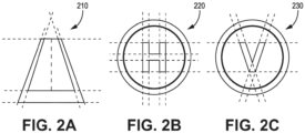
Figure 2A is a schematic diagram of an aircraft runway, for which the system ofFigure 1A can be employed to detect edges on the runway; -
Figure 2B is a schematic diagram of a helipad, for which the system ofFigure 1A can be used to detect markings on the helipad; -
Figure 2C is a schematic diagram of a vertiport, for which the system ofFigure 1A can be employed to detect markings on the vertiport; -
Figure 3 is flow diagram of a method for adaptive feature extraction, according to another exemplary implementation; -
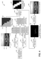
Figure 4 is flow diagram of a method for adaptive feature extraction for use in landing a vehicle at a heliport, according to one example implementation; -
Figure 5 is a schematic depiction of a heliport landing area, which includes a gradient convention of elements as used in the method ofFigure 4 ; -
Figure 6 is a flow diagram of an exemplary method of using image frame transforms to produce an estimated slope of an expected edge feature in the method ofFigure 4 ; -
Figures 7A-7C depict image results of a simulation using the method for adaptive feature extraction, in a vision assisted landing of a vehicle on a helipad; and -
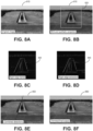
Figures 8A-8F depict image results of a simulation using the method for adaptive feature extraction, in a vision assisted landing of an aircraft on a runway. - In the following detailed description, embodiments are described in sufficient detail to enable those skilled in the art to practice the invention. It is to be understood that other embodiments may be utilized without departing from the scope of the invention. The following detailed description is, therefore, not to be taken in a limiting sense.
- A system and method for adaptive feature extraction to detect letters and/or edges on vehicle landing surfaces is described herein. The present approach provides a way of extracting well defined structures and features from visual data, such as images of runway edges, helipad markings, landing pad markings, or the like. The visual data is captured using one or more onboard vehicle cameras.
- The present method provides for estimating a vehicle pose relative to a plurality of known well-defined features on the ground. The present method reduces the number of detected candidates for a desired feature, and therefore increases integrity of the system by reducing the probability of a mismatch.
- A significant challenge in doing vision-based pose estimation for an aerial vehicle is the accurate detection of corners and edges of a region of interest. Since these scenarios are used in well-defined conditions, such as well-marked runways and helipads, the present approach utilizes this information from a navigation database to improve detection of such edges. For example, a heliport landing area typically has clearly demarcated edges and threshold markings, with well-defined edge thicknesses and lengths.
- In traditional edge detection methods, a conventional gradient filter is used to extract sharp gradients in an image. Gradient filters are usually unidirectional, which means one filter can only extract edges in a particular direction. Hence, multiple filters have to be applied to the same image over and over again, where each filter comprises a particular direction. This traditional approach does a good job of extracting all possible edges in the image, but fails at highlighting a desired edge from undesired edges, and needs multiple iterations of filters on the same image to yield the desired result. Therefore, additional filtering is required to extract required edges from a large set of candidates. The present approach provides such filtering and ensures that the well-defined knowledge of a region of interest is utilized effectively. In addition, using localization information from certified vehicle sensors and a navigation database makes it easier to prove the integrity of the system.
- The present approach provides a visual navigational landing system for aerial vehicles, which includes a technique to adapt feature detection to any predefined shape or feature, such as aruco markers, runway edges, heliport markings, vertiport markings, or any other predefined landing markings. The present approach can be applied in the navigation of various aerial vehicles, including traditional fixed wing airplanes, helicopters, vertical take-off and landing (VTOL) vehicles such as hybrid VTOL vehicles, unmanned aerial vehicles (UAV), unmanned aircraft systems (UAS) vehicles for package delivery, air taxis such as urban air mobility (UAM) vehicles, or the like. The present approach does not require any ground augmentation apart from a distinct runway, strip, helipad, vertiport, or any other designated landing area, on which the aerial vehicle can land. The present method can be used in applications such as providing visual position estimates, sense and avoid, precision landing of aerial vehicles, aircraft visual docking at gates, and the like.
- The present method uses other source of information such as a vehicle's coordinates and a navigation database to get an estimate of a desired edge's slope and length being detected. Moreover, the present method can detect letter marking edges, such as the "H" or "V" or any other known markings on any heliport or vertiport, for various vehicle landing applications.
- The present approach provides richer information in the form of guidance and navigation cues that can be provided to a pilot. The present algorithm can also work in longer ranges (using zoom techniques), where visual acquisition by humans is not feasible.
- In one example, the present method can enable a vision-based UAM landing from a height of about 50-60 m, without any extra equipment on the ground. In another example, the present method can be used for an aircraft glideslope and localizer deviation estimation at distances of around 3 nautical miles from a runway aiming point without the ILS equipment physically being present on the runway.
- Further details related to the present system and method are described as follows and with reference to the drawings.
-
Figure 1A illustrates a vision-basedlanding system 100, according to one embodiment, which employs adaptive feature extraction to detect edges on vehicle landing surfaces. The vision-basedlanding system 100 comprises at least onevision sensor 110 such as a camera, located onboard avehicle 102 such as an aircraft, and at least oneprocessor 120onboard vehicle 102. Theprocessor 120 is operative to receive image data fromvision sensor 110. Theprocessor 120 is in operative communication with adata storage unit 130, which includes anavigation database 132 and alanding area database 134. In one embodiment,data storage unit 130 is locatedonboard vehicle 102. In other embodiments, information fromnavigation database 132 andlanding area database 134 can be relayed tovehicle 102 via a communication link, such as whendata storage unit 130 is located on the ground. - The
processor 120 is also operatively coupled to one or morevehicle aiding sensors 140, which can include one or more inertial sensors such as an inertial measurement unit (IMU), a global navigation satellite system (GNSS) receiver such as a global positioning system (GPS) receiver, a light detection and ranging (LiDAR) device, a radio detection and ranging (RADAR) device, or the like. Theprocessor 120 hosts an adaptivefeature extraction module 122, which has processor readable instructions to perform a method to detect letters and edges on a landing surface forvehicle 102. -
Figure 1B is flow diagram of the method performed by adaptivefeature extraction module 122, according to an exemplary implementation. The method comprises capturing at least one image of a landing area forvehicle 102 usingvision sensor 110, with the landing area including a plurality of edge features (block 150). The method also includes calculating an estimated slope of an expected edge feature of the landing area (block 152), and calculating an expected gradient direction of the expected edge feature (block 153). The method also includes selecting a horizontal basis kernel for an expected edge feature of the landing area, along an expected horizontal gradient (block 154), and selecting a vertical basis kernel for an expected edge feature of the landing area, along an expected vertical gradient (block 155). The method calculates a combined convolution kernel for the expected edge feature, based on the horizontal and vertical basis kernels, the estimated slope of the expected edge feature, and the expected gradient direction of the expected edge feature (block 156). The method then performs a convolution operation on the captured image using the combined convolution kernel to obtain a resulting edge feature image of the landing area (block 158). - Additional details related to implementing the adaptive feature extraction method are described hereafter.
- The adaptive feature extraction method can be implemented as a computer vision algorithm in various applications to detect edges and/or letters on a vehicle landing surface. For example,
Figure 2A is a schematic diagram of anaircraft runway 210, for which the adaptive feature extraction method such as used by vision-based landing system 100 (Fig. 1A ), can be employed to detect edges on theaircraft runway 210.Figure 2B is a schematic diagram of ahelipad 220, for which the adaptive feature extraction method such as used by vision-basedlanding system 100, can be used to detect markings on helipad 220 (e.g., the letter "H").Figure 2C is a schematic diagram of avertiport 230, for which the adaptive feature extraction method such as used by vision-basedlanding system 100, can be employed to detect markings on vertiport 230 (e.g., the letter "C"). -
Figure 3 is flow diagram of amethod 300 for adaptive feature extraction, according to an exemplary implementation. Themethod 300 captures an original image of a landing area with a vehicle camera (block 3 10). Various features in the landing area can be detected with the camera, such as certain objects or markers, using edges, color profiles, heat maps (for infrared images), shapes and patterns. - The
method 300 uses information from anavigation database 320, which provides information about a vehicle landing area of interest such as a heliport or runway, including a position, orientation, dimensions, and marking features of the landing area. For example, information about the landing area can include latitude, longitude, altitude (LLA). Themethod 300 also uses information from one ormore vehicle sensors 322, which provide information about vehicle states, including the vehicle geodetic coordinates and the vehicle attitude such as from onboard inertial sensors. The information fromnavigation database 320 andvehicle sensors 322 is used to compute an estimated slope of an expected edge feature in the landing area (block 324). In addition,method 300 uses information from a landingarea feature database 326, which provides information about various features in the landing area, such as a feature's coarse shape, color, gradient direction, and the like. The information fromfeature database 326 is used to compute an expected gradient direction of the expected edge feature (block 328). - The
method 300 selects a horizontal kernel for the expected edge feature of the landing area (block 332), along an expected horizontal gradient. Themethod 300 also selects a vertical kernel for an expected edge feature of the landing area (block 334), along an expected vertical gradient. Themethod 300 obtains a kernel along the gradient of the expected edge feature (block 336) based on the horizontal and vertical kernels (fromblocks 332 and 334), the estimated slope of the expected edge feature (from block 324), and the expected gradient direction of the expected edge feature (from block 328). Themethod 300 then calculates a combined convolution kernel adapted to the expected gradient of the edge feature (block 338). - The
method 300 then performs a convolution operation (block 342) on the captured image (from block 310) using the combined convolution kernel (from block 338) to obtain a resulting edge feature image. After similar convolution operations of the entire image, a filtered image with edge features extracted is produced (block 344). The filtered image is then further processed to produce a final output for use by the vision navigation system of the vehicle. -
Figure 4 is flow diagram of amethod 400 for adaptive feature extraction for use in landing a vehicle at a heliport, according to one example implementation. Themethod 400 initially captures anoriginal image 410 of the heliport landing area, such by a vehicle camera. As shown inimage 410, a lower pixel intensity pavement is located near the heliport letter "H" feature at 412. A higher pixel intensity pavement is located on the heliport letter "H" feature at 414. A sharp gradient defines the edge of the heliport letter "H" feature at 416. Based on the heliport's information from a database, and a location of the vehicle,original image 410 is narrowed down to a region of interest (ROI) 418. An enlarged view ofROI 418, depicting pixels in a zoomed in section is shown in adigital image 420, which shows how an edge looks in a digital format. The "gradient" referred to here is the rate of change of pixel intensity while moving horizontally or vertically in an image. An edge is qualitatively defined by the sharp change in gradient. - The
method 400 uses a few prerequisites from known sources, including information from a navigation database and vehicle sensors. The navigation database provides prior information about the heliport, including LLA of the landing area. The vehicle sensors provide information about the states of the vehicle, including the vehicle geodetic coordinates, and the vehicle attitude from onboard inertial sensors. This data is used to create a coarse prediction of the heliport, using projection geometry. The information from the navigation database and the vehicle sensors is used to compute an estimated slope of an expected edge feature. The information from a feature database is used to compute an expected gradient direction of the expected edge feature. - For example, edge features in a determined heliport trapezoid are computed from the known sources as indicated at 424, which represents the edges of the letter H" feature in the projected coarse ROI created. The errors in the projection are bounded by the errors in the navigation database and the states of the vehicle. Therefore, in the image frame, the coarse projected heliport is defined by a set of lines whose parameters like slope and y intercept can be computed.
- As shown in
Figure 4 , the cosine of the edge's slope from 424 is calculated at 426, and the sine of the edge's slope from 424 is calculated at 428. These parameters are calculated using the following steps. Initially, the heliport geodetic coordinates and current vehicle geodetic coordinates are converted to Earth-Centered Earth-Fixed (ECEF) coordinates. The ECEF coordinates of the heliport are then converted to vehicle relative North-East-Down (NED) coordinates (navigation frame). Using the attitude of the vehicle from the onboard inertial sensors, the heliport coordinates are converted to a camera frame. With the known intrinsic matrix for the respective camera, the heliport coordinates are converted from the camera frame to an image frame in terms of pixels. Using the start and end pixels representing a letter edge in the image frame, the cosine and sine of the edge's slope is calculated, using the expression:
- The gradient convention of elements as used herein is shown in
Figure 5 , which is a schematic depiction of the heliport landing area. The angle of a selected edge is shown at 510, and the various arrows represent the direction of the gradient. The origin of the image coordinates (0, 0) for the X and Y directions is also shown. - Further details on a method of using image frame transforms to produce the estimated slope of an expected edge feature and an expected gradient direction are described below with respect to
Figure 6 . - Returning to
Figure 4 , a simple horizontal kernel is computed based on the cosine of the edge's slope from 426, and a simple vertical kernel is computed based on the sine of the edge's slope from 428. The simple horizontal and vertical kernels are used as basis kernels. Anexample matrix 432 for the simple horizontal kernel is shown inFigure 4 . A positive horizontal gradient is defined from left to right inmatrix 432, as represented by the increasing magnitude of values inmatrix 432. Anexample matrix 434 for the simple vertical kernel is also depicted. A positive vertical gradient is defined from top to bottom inmatrix 434, as represented by the increasing magnitude of values inmatrix 434. The magnitude of values inmatrix 432 andmatrix 434 can be changed according to an expected gradient strength and the edge's dilution in pixels. - A
matrix 436 is then obtained that represents a combined convolution kernel for the determined edge. Thematrix 436 is obtained after respectively multiplying the cosine and sine values from 426 and 428 with the horizontal and vertical basis kernels represented bymatrices 
- A
convolution operation 438 is then performed ondigital image 420 using the combined convolution kernel represented bymatrix 436. Theconvolution operation 438 can be expressed as:

- The
convolution operation 438 produces a set of resultingimage pixels 440, as shown inFigure 4 . After binarizing resultingimage pixels 440, the desired edge gets demarcated by white pixels (value = 255) of thickness of 1-2 pixels. Both sides of the edge are set to black pixels (value = 0). - A similar convolution operation is then performed on the entire original image, as indicated at 440. A resulting
image 442 is produced, with lines extracted, after the convolution operation. This can be followed by image morphology operations such as erosion and dilation. As shown inFigure 4 , the desired edges can be distinguished in resultingimage 442. Thereafter, an operation to extract and combine the lines from resultingimage 442 is performed, as indicted at 444. This can be done using any common line detection/extraction method like Edge Drawing (ED) lines, Hough transform, or the like. - A
final image output 446, with all the desired edges and lines, is then produced bymethod 400. The lines can be used in post processing to get outputs like ego position, relative position, and other geospatial estimates. - As mentioned above,
Figure 6 is a flow diagram of anexemplary method 600 of using image frame transforms to produce the estimated slope of an expected edge feature, and an expected gradient direction. Althoughmethod 600 is described with respect to a heliport, it should be understood that this method is applicable to other vehicle landing areas. - Initially, a
heliport LLA 610 is obtained from anavigation database 620, to provide heliport geodetic coordinates, and avehicle LLA 612 is obtained fromvehicle sensors 622, to provide vehicle geodetic coordinates. A conversion operation is performed at 614 to convert the geodetic coordinates to ECEF coordinates, which results in heliport ECEF coordinates 616 and vehicle ECEF coordinates 618. A conversion operation is then performed at 624 to convert the ECEF coordinates to vehicle relative NED coordinates, resulting in heliport coordinates in vehicle relative NED frame at 626. - Using a
vehicle attitude 630 fromvehicle sensors 622, a conversion operation is then performed at 632 to convert the relative NED frame to a vehicle body frame, resulting in heliport coordinates in vehicle body frame at 634. A conversion operation is then performed at 636 to convert the body frame relative to the camera frame, resulting in heliport coordinates in camera frame at 638. - Using a known camera intrinsic matrix from a
database 640, a conversion operation is then performed at 642 to convert the camera frame to an image frame, resulting in heliport coordinates in pixels in an image frame at 644. Geometrical slope computations are then performed on the pixels in the image frame at 646, and an estimated slope of the expected edge is output at 648. - As shown in
Figure 6 ,method 600 also uses information from afeature database 650, which provides information about various features in the heliport landing area. Such features include a feature's coarse shape, color information, gradient direction, and the like, as indicated at 652. These features are used to compute an expected gradient direction of the expected edge at 654. -
Figures 7A-7C show the results of the present approach as applied in a simulation, for visual assisted landing of a vehicle on a helipad.Figure 7A depicts anoriginal image 710 of the helipad captured by a vehicle camera.Figure 7B shows a processedimage 720 based onoriginal image 710, with the left edges of the helipad features extracted after application of a kernel.Figure 7C shows a processedimage 730 based onoriginal image 710, with the right edges of the helipad features extracted after application of the kernel. -
Figures 8A-8F show the results of the present approach as applied in a simulation. In particular,Figure 8A depicts anoriginal image 810 of an aircraft runway.Figure 8B shows an ROI andsynthetic projection 820 overlaid onoriginal image 810, which is detected using the navigation database, ownship position, and camera parameters.Figure 8C shows a processedimage 830 of a right edge kernel based on the estimated slope (as per 648 inFig. 6 ) of the runway edges fromsynthetic projection 820.Figure 8D depicts a processedimage 840 with right edge extraction after application of the right edge kernel.Figure 8E shows anoutput image 850 with the combined edge detections, andFigure 8F depicts a trimmedfinal output image 860, which can be employed in various post processing navigation operations. - The processing units and/or other computational devices used in the method and system described herein may be implemented using software, firmware, hardware, or appropriate combinations thereof. The processing unit and/or other computational devices may be supplemented by, or incorporated in, specially-designed application-specific integrated circuits (ASICs) or field programmable gate arrays (FPGAs). In some implementations, the processing unit and/or other computational devices may communicate through an additional transceiver with other computing devices outside of the system, such as those associated with a management system or computing devices associated with other subsystems controlled by the management system. The processing unit and/or other computational devices can also include or function with software programs, firmware, or other computer readable instructions for carrying out various process tasks, calculations, and control functions used in the methods and systems described herein.
- The methods described herein may be implemented by computer executable instructions, such as program modules or components, which are executed by at least one processor or processing unit. Generally, program modules include routines, programs, objects, data components, data structures, algorithms, and the like, which perform particular tasks or implement particular abstract data types.
- Instructions for carrying out the various process tasks, calculations, and generation of other data used in the operation of the methods described herein can be implemented in software, firmware, or other computer readable instructions. These instructions are typically stored on appropriate computer program products that include computer readable media used for storage of computer readable instructions or data structures. Such a computer readable medium may be available media that can be accessed by a general purpose or special purpose computer or processor, or any programmable logic device.
- Suitable computer readable storage media may include, for example, non-volatile memory devices including semi-conductor memory devices such as Random Access Memory (RAM), Read Only Memory (ROM), Electrically Erasable Programmable ROM (EEPROM), or flash memory devices; magnetic disks such as internal hard disks or removable disks; optical storage devices such as compact discs (CDs), digital versatile discs (DVDs), Blu-ray discs; or any other media that can be used to carry or store desired program code in the form of computer executable instructions or data structures.
- Example 1 includes a vison-based landing system, comprising: at least one processor onboard an aerial vehicle, at least one vision sensor onboard the aerial vehicle and operatively coupled to the at least one processor, one or more aiding sensors onboard the aerial vehicle and operatively coupled to the at least one processor; and a data storage unit in operative communication with the at least one processor; wherein the at least one processor hosts an adaptive feature extraction module, which has processor readable instructions to perform a method to detect edges on a landing area for the aerial vehicle, the method comprising: capturing at least one image of the landing area with the at least one vison sensor, wherein the landing area includes a plurality of edge features; calculating an estimated slope of an expected edge feature of the landing area; calculating an expected gradient direction of the expected edge feature; selecting a horizontal basis kernel for the expected edge feature along an expected horizontal gradient; selecting a vertical basis kernel for the expected edge feature along an expected vertical gradient; calculating a combined convolution kernel for the expected edge feature based on the horizontal and vertical basis kernels, the estimated slope of the expected edge feature, and the expected gradient direction of the expected edge feature; and performing a convolution operation on the at least one image using the combined convolution kernel to obtain a resulting edge feature image of the landing area.
- Example 2 includes the system of Example 1, wherein the aerial vehicle comprises a fixed wing airplane, a helicopter, a vertical take-off and landing (VTOL) vehicle, an unmanned aerial vehicle (UAV), an unmanned aircraft systems (UAS) vehicle, or an urban air mobility (UAM) vehicle.
- Example 3 includes the system of any of Examples 1-2, wherein at least one vision sensor comprises a camera.
- Example 4 includes the system of any of Examples 1-3, wherein the one or more aiding sensors comprise one or more inertial sensors, a global navigation satellite system (GNSS) receiver, a light detection and ranging (LiDAR) device, or a radio detection and ranging (RADAR) device.
- Example 5 includes the system of any of Examples 1-4, wherein the one or more aiding sensors are configured to provide information about a state of the aerial vehicle, including geodetic coordinates of the aerial vehicle, and an attitude of the aerial vehicle.
- Example 6 includes the system of any of Examples 1-5, wherein the data storage unit includes a navigation database, and a landing area feature database.
- Example 7 includes the system of Example 6, wherein information from the navigation database and the landing area feature database can be relayed to the aerial vehicle via a communication link.
- Example 8 includes the system of any of Examples 6-7, wherein the navigation database is configured to provide information about the landing area, including a position, orientation, dimensions, and marking features of the landing area.
- Example 9 includes the system of Example 8, wherein the information from the navigation database and the one or more aiding sensors is used to calculate the estimated slope of the expected edge feature.
- Example 10 includes the system of any of Examples 6-9, wherein the landing area feature database is configured to provide information about the edge features in the landing area, including coarse shape, color, and gradient direction.
- Example 11 includes the system of Example 10, wherein the information from the landing area feature database is used to calculate the expected gradient direction of the expected edge feature.
- Example 12 includes the system of any of Examples 1-11, wherein the landing area includes an aircraft runway, a helipad, a vertiport, or any other designated landing area.
- Example 13 includes the system of any of Examples 1-12, wherein the plurality of edge features comprise runway edges, heliport markings, vertiport markings, aruco markers, or any other pre-defined landing markings.
- Example 14 includes a method for vison-based landing, the method comprising: capturing at least one image of a landing area for an aerial vehicle, the landing area including a plurality of edge features; calculating an estimated slope of an expected edge feature of the landing area; calculating an expected gradient direction of the expected edge feature; selecting a horizontal basis kernel for the expected edge feature along an expected horizontal gradient; selecting a vertical basis kernel for the expected edge feature along an expected vertical gradient; calculating a combined convolution kernel for the expected edge feature based on the horizontal and vertical basis kernels, the estimated slope of the expected edge feature, and the expected gradient direction of the expected edge feature; and performing a convolution operation on the at least one image using the combined convolution kernel to obtain a resulting edge feature image of the landing area.
- Example 15 includes the method of Example 14, wherein information from a navigation database and one or more vehicle aiding sensors is used to calculate the estimated slope of the expected edge feature.
- Example 16 includes the method of Example 15, wherein the information from the navigation database and the one or more vehicle aiding sensors is processed using image frame transforms to produce the estimated slope of the expected edge feature.
- Example 17 includes the method of any of Examples 14-16, wherein information from a landing area feature database is used to calculate the expected gradient direction of the expected edge feature.
- Example 18 includes the method of any of Examples 14-17, wherein the resulting edge feature image of the landing area includes extracted lines based on the plurality of edge features.
- Example 19 includes the method of any of Examples 14-18, wherein the landing area comprises an aircraft runway, a helipad, or a vertiport; and the plurality of edge features comprise runway edges, heliport markings, vertiport markings, or aruco markers.
- Example 20 includes the method of any of Examples 14-19, wherein the aerial vehicle comprises a fixed wing airplane, a helicopter, a vertical take-off and landing (VTOL) vehicle, an unmanned aerial vehicle (UAV), an unmanned aircraft systems (UAS) vehicle, or an urban air mobility (UAM) vehicle.
- From the foregoing, it will be appreciated that, although specific embodiments have been described herein for purposes of illustration, various modifications may be made without deviating from the scope of the disclosure. Thus, the described embodiments are to be considered in all respects only as illustrative and not restrictive. In addition, all changes that come within the meaning and range of equivalency of the claims are to be embraced within their scope.
Claims (10)
- A vison-based landing system, comprising:at least one processor onboard an aerial vehicle,at least one vision sensor onboard the aerial vehicle and operatively coupled to the at least one processor,one or more aiding sensors onboard the aerial vehicle and operatively coupled to the at least one processor; anda data storage unit in operative communication with the at least one processor;wherein the at least one processor hosts an adaptive feature extraction module, which has processor readable instructions to perform a method to detect edges on a landing area for the aerial vehicle, the method comprising:capturing at least one image of the landing area with the at least one vison sensor, wherein the landing area includes a plurality of edge features;calculating an estimated slope of an expected edge feature of the landing area;calculating an expected gradient direction of the expected edge feature;selecting a horizontal basis kernel for the expected edge feature along an expected horizontal gradient;selecting a vertical basis kernel for the expected edge feature along an expected vertical gradient;calculating a combined convolution kernel for the expected edge feature based on the horizontal and vertical basis kernels, the estimated slope of the expected edge feature, and the expected gradient direction of the expected edge feature; andperforming a convolution operation on the at least one image using the combined convolution kernel to obtain a resulting edge feature image of the landing area.
- The system of claim 1, wherein the aerial vehicle comprises a fixed wing airplane, a helicopter, a vertical take-off and landing (VTOL) vehicle, an unmanned aerial vehicle (UAV), an unmanned aircraft systems (UAS) vehicle, or an urban air mobility (UAM) vehicle.
- The system of claim 1, wherein the one or more aiding sensors are configured to provide information about a state of the aerial vehicle, including geodetic coordinates of the aerial vehicle, and an attitude of the aerial vehicle.
- The system of claim 1, wherein the data storage unit includes a navigation database, and a landing area feature database.
- The system of claim 4, wherein information from the navigation database and the landing area feature database can be relayed to the aerial vehicle via a communication link.
- The system of claim 4, wherein the navigation database is configured to provide information about the landing area, including a position, orientation, dimensions, and marking features of the landing area.
- The system of claim 6, wherein the information from the navigation database and the one or more aiding sensors is used to calculate the estimated slope of the expected edge feature.
- The system of claim 4, wherein the landing area feature database is configured to provide information about the edge features in the landing area, including coarse shape, color, and gradient direction.
- The system of claim 8, wherein the information from the landing area feature database is used to calculate the expected gradient direction of the expected edge feature.
- A method for vison-based landing, the method comprising:capturing at least one image of a landing area for an aerial vehicle, the landing area including a plurality of edge features;calculating an estimated slope of an expected edge feature of the landing area;calculating an expected gradient direction of the expected edge feature;selecting a horizontal basis kernel for the expected edge feature along an expected horizontal gradient;selecting a vertical basis kernel for the expected edge feature along an expected vertical gradient;calculating a combined convolution kernel for the expected edge feature based on the horizontal and vertical basis kernels, the estimated slope of the expected edge feature, and the expected gradient direction of the expected edge feature; andperforming a convolution operation on the at least one image using the combined convolution kernel to obtain a resulting edge feature image of the landing area.
Applications Claiming Priority (2)
| Application Number | Priority Date | Filing Date | Title |
|---|---|---|---|
| IN202211011854 | 2022-03-04 | ||
| US17/726,007 US12347204B2 (en) | 2022-03-04 | 2022-04-21 | Adaptive feature extraction to detect letters and edges on vehicle landing surfaces |
Publications (2)
| Publication Number | Publication Date |
|---|---|
| EP4239587A1 true EP4239587A1 (en) | 2023-09-06 |
| EP4239587B1 EP4239587B1 (en) | 2025-09-03 |
Family
ID=85227265
Family Applications (1)
| Application Number | Title | Priority Date | Filing Date |
|---|---|---|---|
| EP23156413.9A Active EP4239587B1 (en) | 2022-03-04 | 2023-02-13 | Adaptive feature extraction to detect letters and edges on vehicle landing surfaces |
Country Status (1)
| Country | Link |
|---|---|
| EP (1) | EP4239587B1 (en) |
Citations (1)
| Publication number | Priority date | Publication date | Assignee | Title |
|---|---|---|---|---|
| US6157876A (en) * | 1999-10-12 | 2000-12-05 | Honeywell International Inc. | Method and apparatus for navigating an aircraft from an image of the runway |
-
2023
- 2023-02-13 EP EP23156413.9A patent/EP4239587B1/en active Active
Patent Citations (1)
| Publication number | Priority date | Publication date | Assignee | Title |
|---|---|---|---|---|
| US6157876A (en) * | 1999-10-12 | 2000-12-05 | Honeywell International Inc. | Method and apparatus for navigating an aircraft from an image of the runway |
Non-Patent Citations (4)
| Title |
|---|
| ABU-JBARA KHALED ET AL: "A robust vision-based runway detection and tracking algorithm for automatic UAV landing", 2015 INTERNATIONAL CONFERENCE ON UNMANNED AIRCRAFT SYSTEMS (ICUAS), IEEE, 9 June 2015 (2015-06-09), pages 1148 - 1157, XP033171616, DOI: 10.1109/ICUAS.2015.7152407 * |
| ANGERMANN M ET AL: "High Precision Approaches Enabled by an Optical-Based Navigation System", PNT 2015 - PROCEEDINGS OF THE ION 2015 PACIFIC PNT MEETING, THE INSTITUTE OF NAVIGATION, 8551 RIXLEW LANE SUITE 360 MANASSAS, VA 20109, USA, 23 April 2015 (2015-04-23), pages 694 - 701, XP056017433 * |
| JOHN CANNY: "A Computational Approach to Edge Detection", IEEE TRANSACTIONS ON PATTERN ANALYSIS AND MACHINE INTELLIGENCE, IEEE COMPUTER SOCIETY, USA, vol. 30, no. 6, 1 November 1986 (1986-11-01), pages 679 - 698, XP011242974, ISSN: 0162-8828 * |
| LI JIAN ET AL: "Efficient Filtering for Edge Extraction under Perspective Effect", APPLIED SCIENCES, vol. 11, no. 18, 15 September 2021 (2021-09-15), pages 8558, XP093055015, DOI: 10.3390/app11188558 * |
Also Published As
| Publication number | Publication date |
|---|---|
| EP4239587B1 (en) | 2025-09-03 |
Similar Documents
| Publication | Publication Date | Title |
|---|---|---|
| Marut et al. | ArUco markers pose estimation in UAV landing aid system | |
| CN109324337B (en) | Unmanned aerial vehicle route generation and positioning method and device and unmanned aerial vehicle | |
| CN110222612B (en) | Dynamic target recognition and tracking method for autonomous landing of UAV | |
| US10054445B2 (en) | Vision-aided aerial navigation | |
| US8073584B2 (en) | Method for measuring dynamic parameters of an aircraft progressing over an airport zone | |
| EP2850455B1 (en) | Point cloud visualization of acceptable helicopter landing zones based on 4d lidar | |
| US20200201360A1 (en) | Systems and methods for automated landing of a drone | |
| EP2096602B1 (en) | Methods and apparatus for runway segmentation using sensor analysis | |
| EP3961578B1 (en) | Perception-based autonomous landing for aircraft | |
| EP2818957A1 (en) | System and method for UAV landing | |
| US20130027554A1 (en) | Method and Apparatus for Automated Camera Location and Orientation with Image Processing and Alignment to Ground Based Reference Point(s) | |
| CN103852077B (en) | Automatic anti-cheating judgment method for unmanned aerial vehicle positioning information in link failure process | |
| KR102782302B1 (en) | Method and device to estimate location | |
| EP4032813B1 (en) | Computer vision systems and methods for aiding landing decision | |
| EP3980718B1 (en) | Error correction of airborne vehicles using natural patterns | |
| US12347204B2 (en) | Adaptive feature extraction to detect letters and edges on vehicle landing surfaces | |
| Vu et al. | Traffic sign detection, state estimation, and identification using onboard sensors | |
| Anitha et al. | Vision based autonomous landing of an unmanned aerial vehicle | |
| Vegula et al. | Detection of runway and obstacles using electro-optical and infrared sensors before landing | |
| EP4239587B1 (en) | Adaptive feature extraction to detect letters and edges on vehicle landing surfaces | |
| CN115457129A (en) | Aircraft positioning method and device, electronic equipment and storage medium | |
| Paszkuta et al. | UAV on-board emergency safe landing spot detection system combining classical and deep learning-based segmentation methods | |
| EP3876217A1 (en) | Methods and systems for highlighting ground traffic on cockpit displays | |
| Lin et al. | Experimental observation and assessment of ice conditions with a fixed-wing unmanned aerial vehicle over Yellow River, China | |
| Javanmardi et al. | 3D building map reconstruction in dense urban areas by integrating airborne laser point cloud with 2D boundary map |
Legal Events
| Date | Code | Title | Description |
|---|---|---|---|
| PUAI | Public reference made under article 153(3) epc to a published international application that has entered the european phase |
Free format text: ORIGINAL CODE: 0009012 |
|
| STAA | Information on the status of an ep patent application or granted ep patent |
Free format text: STATUS: THE APPLICATION HAS BEEN PUBLISHED |
|
| AK | Designated contracting states |
Kind code of ref document: A1 Designated state(s): AL AT BE BG CH CY CZ DE DK EE ES FI FR GB GR HR HU IE IS IT LI LT LU LV MC ME MK MT NL NO PL PT RO RS SE SI SK SM TR |
|
| STAA | Information on the status of an ep patent application or granted ep patent |
Free format text: STATUS: REQUEST FOR EXAMINATION WAS MADE |
|
| 17P | Request for examination filed |
Effective date: 20230921 |
|
| RBV | Designated contracting states (corrected) |
Designated state(s): AL AT BE BG CH CY CZ DE DK EE ES FI FR GB GR HR HU IE IS IT LI LT LU LV MC ME MK MT NL NO PL PT RO RS SE SI SK SM TR |
|
| GRAP | Despatch of communication of intention to grant a patent |
Free format text: ORIGINAL CODE: EPIDOSNIGR1 |
|
| STAA | Information on the status of an ep patent application or granted ep patent |
Free format text: STATUS: GRANT OF PATENT IS INTENDED |
|
| INTG | Intention to grant announced |
Effective date: 20250404 |
|
| RIC1 | Information provided on ipc code assigned before grant |
Ipc: G05D 1/00 20060101ALI20250328BHEP Ipc: G08G 5/54 20250101ALI20250328BHEP Ipc: G08G 5/21 20250101ALI20250328BHEP Ipc: G06V 20/10 20220101ALI20250328BHEP Ipc: G06V 20/17 20220101ALI20250328BHEP Ipc: G06V 10/44 20220101AFI20250328BHEP |
|
| GRAS | Grant fee paid |
Free format text: ORIGINAL CODE: EPIDOSNIGR3 |
|
| GRAA | (expected) grant |
Free format text: ORIGINAL CODE: 0009210 |
|
| STAA | Information on the status of an ep patent application or granted ep patent |
Free format text: STATUS: THE PATENT HAS BEEN GRANTED |
|
| AK | Designated contracting states |
Kind code of ref document: B1 Designated state(s): AL AT BE BG CH CY CZ DE DK EE ES FI FR GB GR HR HU IE IS IT LI LT LU LV MC ME MK MT NL NO PL PT RO RS SE SI SK SM TR |
|
| REG | Reference to a national code |
Ref country code: CH Ref legal event code: EP |
|
| REG | Reference to a national code |
Ref country code: DE Ref legal event code: R096 Ref document number: 602023006205 Country of ref document: DE |
|
| P01 | Opt-out of the competence of the unified patent court (upc) registered |
Free format text: CASE NUMBER: UPC_APP_3590_4239587/2025 Effective date: 20250818 |
|
| REG | Reference to a national code |
Ref country code: IE Ref legal event code: FG4D |
|
| REG | Reference to a national code |
Ref country code: NL Ref legal event code: MP Effective date: 20250903 |
|
| PG25 | Lapsed in a contracting state [announced via postgrant information from national office to epo] |
Ref country code: NO Free format text: LAPSE BECAUSE OF FAILURE TO SUBMIT A TRANSLATION OF THE DESCRIPTION OR TO PAY THE FEE WITHIN THE PRESCRIBED TIME-LIMIT Effective date: 20251203 |
|
| REG | Reference to a national code |
Ref country code: LT Ref legal event code: MG9D |
|
| PG25 | Lapsed in a contracting state [announced via postgrant information from national office to epo] |
Ref country code: FI Free format text: LAPSE BECAUSE OF FAILURE TO SUBMIT A TRANSLATION OF THE DESCRIPTION OR TO PAY THE FEE WITHIN THE PRESCRIBED TIME-LIMIT Effective date: 20250903 |
|
| PG25 | Lapsed in a contracting state [announced via postgrant information from national office to epo] |
Ref country code: HR Free format text: LAPSE BECAUSE OF FAILURE TO SUBMIT A TRANSLATION OF THE DESCRIPTION OR TO PAY THE FEE WITHIN THE PRESCRIBED TIME-LIMIT Effective date: 20250903 |
|
| PG25 | Lapsed in a contracting state [announced via postgrant information from national office to epo] |
Ref country code: GR Free format text: LAPSE BECAUSE OF FAILURE TO SUBMIT A TRANSLATION OF THE DESCRIPTION OR TO PAY THE FEE WITHIN THE PRESCRIBED TIME-LIMIT Effective date: 20251204 |
|
| PG25 | Lapsed in a contracting state [announced via postgrant information from national office to epo] |
Ref country code: SE Free format text: LAPSE BECAUSE OF FAILURE TO SUBMIT A TRANSLATION OF THE DESCRIPTION OR TO PAY THE FEE WITHIN THE PRESCRIBED TIME-LIMIT Effective date: 20250903 |
|
| PG25 | Lapsed in a contracting state [announced via postgrant information from national office to epo] |
Ref country code: LV Free format text: LAPSE BECAUSE OF FAILURE TO SUBMIT A TRANSLATION OF THE DESCRIPTION OR TO PAY THE FEE WITHIN THE PRESCRIBED TIME-LIMIT Effective date: 20250903 |
|
| PG25 | Lapsed in a contracting state [announced via postgrant information from national office to epo] |
Ref country code: BG Free format text: LAPSE BECAUSE OF FAILURE TO SUBMIT A TRANSLATION OF THE DESCRIPTION OR TO PAY THE FEE WITHIN THE PRESCRIBED TIME-LIMIT Effective date: 20250903 Ref country code: PL Free format text: LAPSE BECAUSE OF FAILURE TO SUBMIT A TRANSLATION OF THE DESCRIPTION OR TO PAY THE FEE WITHIN THE PRESCRIBED TIME-LIMIT Effective date: 20250903 |
|
| PG25 | Lapsed in a contracting state [announced via postgrant information from national office to epo] |
Ref country code: RS Free format text: LAPSE BECAUSE OF FAILURE TO SUBMIT A TRANSLATION OF THE DESCRIPTION OR TO PAY THE FEE WITHIN THE PRESCRIBED TIME-LIMIT Effective date: 20251203 |
|
| PG25 | Lapsed in a contracting state [announced via postgrant information from national office to epo] |
Ref country code: ES Free format text: LAPSE BECAUSE OF FAILURE TO SUBMIT A TRANSLATION OF THE DESCRIPTION OR TO PAY THE FEE WITHIN THE PRESCRIBED TIME-LIMIT Effective date: 20250903 |
|
| REG | Reference to a national code |
Ref country code: AT Ref legal event code: MK05 Ref document number: 1834050 Country of ref document: AT Kind code of ref document: T Effective date: 20250903 |
|
| PG25 | Lapsed in a contracting state [announced via postgrant information from national office to epo] |
Ref country code: NL Free format text: LAPSE BECAUSE OF FAILURE TO SUBMIT A TRANSLATION OF THE DESCRIPTION OR TO PAY THE FEE WITHIN THE PRESCRIBED TIME-LIMIT Effective date: 20250903 |
|
| PG25 | Lapsed in a contracting state [announced via postgrant information from national office to epo] |
Ref country code: SM Free format text: LAPSE BECAUSE OF FAILURE TO SUBMIT A TRANSLATION OF THE DESCRIPTION OR TO PAY THE FEE WITHIN THE PRESCRIBED TIME-LIMIT Effective date: 20250903 |
|
| PGFP | Annual fee paid to national office [announced via postgrant information from national office to epo] |
Ref country code: DE Payment date: 20260220 Year of fee payment: 4 |
|
| PG25 | Lapsed in a contracting state [announced via postgrant information from national office to epo] |
Ref country code: AT Free format text: LAPSE BECAUSE OF FAILURE TO SUBMIT A TRANSLATION OF THE DESCRIPTION OR TO PAY THE FEE WITHIN THE PRESCRIBED TIME-LIMIT Effective date: 20250903 |
|
| PG25 | Lapsed in a contracting state [announced via postgrant information from national office to epo] |
Ref country code: IT Free format text: LAPSE BECAUSE OF FAILURE TO SUBMIT A TRANSLATION OF THE DESCRIPTION OR TO PAY THE FEE WITHIN THE PRESCRIBED TIME-LIMIT Effective date: 20250903 |
|
| PG25 | Lapsed in a contracting state [announced via postgrant information from national office to epo] |
Ref country code: IS Free format text: LAPSE BECAUSE OF FAILURE TO SUBMIT A TRANSLATION OF THE DESCRIPTION OR TO PAY THE FEE WITHIN THE PRESCRIBED TIME-LIMIT Effective date: 20260103 |
|
| PG25 | Lapsed in a contracting state [announced via postgrant information from national office to epo] |
Ref country code: PT Free format text: LAPSE BECAUSE OF FAILURE TO SUBMIT A TRANSLATION OF THE DESCRIPTION OR TO PAY THE FEE WITHIN THE PRESCRIBED TIME-LIMIT Effective date: 20260105 Ref country code: CZ Free format text: LAPSE BECAUSE OF FAILURE TO SUBMIT A TRANSLATION OF THE DESCRIPTION OR TO PAY THE FEE WITHIN THE PRESCRIBED TIME-LIMIT Effective date: 20250903 |
|
| PG25 | Lapsed in a contracting state [announced via postgrant information from national office to epo] |
Ref country code: SK Free format text: LAPSE BECAUSE OF FAILURE TO SUBMIT A TRANSLATION OF THE DESCRIPTION OR TO PAY THE FEE WITHIN THE PRESCRIBED TIME-LIMIT Effective date: 20250903 Ref country code: EE Free format text: LAPSE BECAUSE OF FAILURE TO SUBMIT A TRANSLATION OF THE DESCRIPTION OR TO PAY THE FEE WITHIN THE PRESCRIBED TIME-LIMIT Effective date: 20250903 |
|
| REG | Reference to a national code |
Ref country code: DE Ref legal event code: R097 Ref document number: 602023006205 Country of ref document: DE |
|
| PG25 | Lapsed in a contracting state [announced via postgrant information from national office to epo] |
Ref country code: LT Free format text: LAPSE BECAUSE OF FAILURE TO SUBMIT A TRANSLATION OF THE DESCRIPTION OR TO PAY THE FEE WITHIN THE PRESCRIBED TIME-LIMIT Effective date: 20250903 |
|
| PG25 | Lapsed in a contracting state [announced via postgrant information from national office to epo] |
Ref country code: DK Free format text: LAPSE BECAUSE OF FAILURE TO SUBMIT A TRANSLATION OF THE DESCRIPTION OR TO PAY THE FEE WITHIN THE PRESCRIBED TIME-LIMIT Effective date: 20250903 |
|
| PLBE | No opposition filed within time limit |
Free format text: ORIGINAL CODE: 0009261 |
|
| STAA | Information on the status of an ep patent application or granted ep patent |
Free format text: STATUS: NO OPPOSITION FILED WITHIN TIME LIMIT |
|
| REG | Reference to a national code |
Ref country code: CH Ref legal event code: L10 Free format text: ST27 STATUS EVENT CODE: U-0-0-L10-L00 (AS PROVIDED BY THE NATIONAL OFFICE) Effective date: 20260715 |
|
| 26N | No opposition filed |
Effective date: 20260604 |