EP4239579A1 - Systems and methods for monocular depth estimation - Google Patents
Systems and methods for monocular depth estimation Download PDFInfo
- Publication number
- EP4239579A1 EP4239579A1 EP22159784.2A EP22159784A EP4239579A1 EP 4239579 A1 EP4239579 A1 EP 4239579A1 EP 22159784 A EP22159784 A EP 22159784A EP 4239579 A1 EP4239579 A1 EP 4239579A1
- Authority
- EP
- European Patent Office
- Prior art keywords
- depth
- pixel
- plane
- offset
- seed
- Prior art date
- Legal status (The legal status is an assumption and is not a legal conclusion. Google has not performed a legal analysis and makes no representation as to the accuracy of the status listed.)
- Granted
Links
Images



Classifications
-
- G—PHYSICS
- G06—COMPUTING OR CALCULATING; COUNTING
- G06T—IMAGE DATA PROCESSING OR GENERATION, IN GENERAL
- G06T7/00—Image analysis
- G06T7/50—Depth or shape recovery
-
- G—PHYSICS
- G06—COMPUTING OR CALCULATING; COUNTING
- G06N—COMPUTING ARRANGEMENTS BASED ON SPECIFIC COMPUTATIONAL MODELS
- G06N3/00—Computing arrangements based on biological models
- G06N3/02—Neural networks
- G06N3/04—Architecture, e.g. interconnection topology
- G06N3/0464—Convolutional networks [CNN, ConvNet]
-
- G—PHYSICS
- G06—COMPUTING OR CALCULATING; COUNTING
- G06N—COMPUTING ARRANGEMENTS BASED ON SPECIFIC COMPUTATIONAL MODELS
- G06N3/00—Computing arrangements based on biological models
- G06N3/02—Neural networks
- G06N3/08—Learning methods
-
- G—PHYSICS
- G06—COMPUTING OR CALCULATING; COUNTING
- G06N—COMPUTING ARRANGEMENTS BASED ON SPECIFIC COMPUTATIONAL MODELS
- G06N3/00—Computing arrangements based on biological models
- G06N3/02—Neural networks
- G06N3/08—Learning methods
- G06N3/084—Backpropagation, e.g. using gradient descent
-
- G—PHYSICS
- G06—COMPUTING OR CALCULATING; COUNTING
- G06N—COMPUTING ARRANGEMENTS BASED ON SPECIFIC COMPUTATIONAL MODELS
- G06N3/00—Computing arrangements based on biological models
- G06N3/02—Neural networks
- G06N3/08—Learning methods
- G06N3/09—Supervised learning
-
- G—PHYSICS
- G06—COMPUTING OR CALCULATING; COUNTING
- G06N—COMPUTING ARRANGEMENTS BASED ON SPECIFIC COMPUTATIONAL MODELS
- G06N3/00—Computing arrangements based on biological models
- G06N3/02—Neural networks
- G06N3/08—Learning methods
- G06N3/0985—Hyperparameter optimisation; Meta-learning; Learning-to-learn
-
- G—PHYSICS
- G06—COMPUTING OR CALCULATING; COUNTING
- G06T—IMAGE DATA PROCESSING OR GENERATION, IN GENERAL
- G06T2207/00—Indexing scheme for image analysis or image enhancement
- G06T2207/20—Special algorithmic details
- G06T2207/20081—Training; Learning
-
- G—PHYSICS
- G06—COMPUTING OR CALCULATING; COUNTING
- G06T—IMAGE DATA PROCESSING OR GENERATION, IN GENERAL
- G06T2207/00—Indexing scheme for image analysis or image enhancement
- G06T2207/20—Special algorithmic details
- G06T2207/20084—Artificial neural networks [ANN]
Definitions
- the present invention relates to the field of image processing and, in particular, to the estimation of depth of three-dimensional (3D) points represented by pixels in images. More particularly, the invention relates to depth estimation systems and computer-implemented depth estimation methods that determine depth based on monocular data (i.e., data obtained from a single camera/viewpoint, as opposed to stereo image data).
- monocular data i.e., data obtained from a single camera/viewpoint, as opposed to stereo image data.
- Depth estimation is a fundamental problem in computer vision. In general, it involves determining a value for the perpendicular coordinate of the 3D point depicted at a pixel of an image. The determined value may be considered to be an estimate or prediction of the true depth of the relevant 3D point.
- the processed image data corresponds to a still image or to a frame of a video.
- Depth-estimation is important in a wide range of applications, including robotics and autonomous cars, and forms part of preliminary processing that enables an automatic system to interpret a scene and implement downstream tasks (e.g., to drive actuators and motors so that a robotic hand can grasp an object, to control steering in an autonomous vehicle so as to avoid an obstacle, and so on). Indeed, there is experimental evidence that, together with semantic segmentation, depth is the most vital vision-level cue for automatic systems to execute actions.
- the present invention addresses depth estimation in the context where the source image data is monocular (i.e., generated by a single imaging device/camera).
- monocular depth estimation involves the challenge of scale ambiguity, as the same input image can be generated by infinitely many 3D scenes.
- the current trend in performing monocular depth estimation involves use of fully convolutional neural networks that output a dense depth prediction (i.e., a prediction of depth for each pixel in the image) and are trained to perform an end-to-end mapping from image data to depth maps, either with standard supervision on depth or with self-supervision by using the predicted depth to reconstruct neighbouring views of the scene.
- Most supervised approaches train the network using a loss function that is computed independently for each pixel, i.e., predictions at different pixels are treated separately.
- Such approaches ignore the high degree of regularity that exists in real-world 3D scenes, which generally yield depth maps that are piecewise smooth (i.e., real-world scenes tend to contain many regions within which neighbouring pixels have the same or similar depths).
- Planes are the local first-order Taylor approximation for locally differentiable depth maps and they are easy to parameterize using three independent coefficients. Once a pixel is associated with a plane, its depth can be recovered from the position of the pixel and the coefficients of the associated plane. Some known systems explicitly predict the planes in a 3D scene represented by the image data. However, the accuracy of depth predictions made using known approaches is not as high as desired.
- the present invention has been made in the light of the above problems.
- the present invention provides a depth-estimation system to estimate depth of three-dimensional points corresponding to pixels in an image representing a three-dimensional scene, the depth-estimation system comprising:
- the monocular depth-estimation system according to the invention achieves depth-estimation performance which exceeds that of the state-of-the-art monocular depth-estimation systems, as demonstrated in experimental studies discussed below.
- the offset-vector-field detector is configured to generate a confidence map indicative of a level of confidence that a seed pixel is in the same plane as a target pixel, and to supply the confidence map to the fusion unit; and the fusion unit is configured to weight the first and second depth estimates based on confidence values in the confidence map generated by the offset vector field generator.
- the seed-pixel-based depth estimator is configured to refine the offset vector field by cascading the offset vectors multiple times before resampling the plane coefficients, wherein a single cascading step consists in sampling the position p + o(p) + o(p + o(p)).
- the neural network architecture has been trained in a supervised end-to-end training process which minimizes a loss function L depth defined according to the equation below:
- L depth L D f , D * + ⁇ L D s , D * + ⁇ L D i , D *
- D f is the final depth estimate produced by the fusion unit
- D ⁇ is the ground truth depth
- D s is the second depth estimate produced by the seed-pixel-based depth estimator
- D i is the first depth estimate produced by the pixel-based depth estimator
- ( D f , D ⁇ ) is a loss function that penalizes deviations between the final depth estimate produced by the fusion unit and the ground truth
- L ( D s , D ⁇ ) is a loss function that penalizes deviations between the second depth estimate produced by the seed-pixel-based depth estimator and the ground truth
- L ( D i , D ⁇ ) is a loss function that penalizes deviations between the first depth estimate produced by the
- the supervised end-to-end training process may seek to minimize a total loss function L total which includes a mean patch loss L MPL additional to L depth
- K are all the non-overlapping patches in D f and D ⁇
- n k is the normal to a given patch k.
- Certain embodiments of the invention further comprise a guidance module.
- the training may seek to minimize a total loss function L total which includes a mean patch loss L MPL additional to L depth
- the above-recited training method produces a trained depth-estimation system as mentioned above, with its concomitant advantages.
- the present invention still further provides a computer-implemented method of estimating depth of three-dimensional points corresponding to pixels in an image representing a three-dimensional scene, the method comprising:
- the above-mentioned method may further comprise, in the second parallel path, the generating of a confidence map indicative of a level of confidence that a seed pixel is in the same plane as a target pixel, and the combining may comprise weighting the first and second depth estimates based on confidence values in the confidence map.
- the offset vector field may be refined by cascading the offset vectors multiple times before the plane coefficients are resampled to generate the second depth estimate, wherein a single cascading step consists in sampling the position p + o(p) + o(p + o(p)).
- a single cascading step consists in sampling the position p + o(p) + o(p + o(p)).
- the invention proposes a new CNN-based architecture configured to perform depth estimation. Based on knowledge about the high regularity of real 3D scenes, the CNN architecture according to the invention is trained to selectively leverage information from coplanar pixels to improve the depth predictions.
- the technique is based on a piecewise planarity prior (base assumption) which states that for each pixel, there is a seed pixel which shares the same planar 3D surface with the former.
- the invention proposes a CNN-based architecture comprising a novel combination of two heads, as illustrated in Fig.1 .
- One head is a pixel-based depth estimator and the other head is a seed-pixel-base depth estimator.
- the two heads of the network share a common encoder and have separate decoders, as shown in Fig.1 and as discussed below with reference to Figs.6-10 .
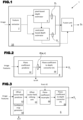
- Fig.1 is a schematic representation of main modules comprised in the depth-estimation system 1 according to a first, generic embodiment of the invention.
- a monocular image stream is input to the common encoder, i.e., feature extractor 2, and the feature data from the common encoder is processed in parallel by the pixel-based depth estimator backbone 4, which includes functionality to estimate plane coefficients, and a seed-pixel-based depth estimator backbone 6, which includes functionality to generate an offset-vector field.
- the input data stream represents a scene imaged by an image-capture device such as a video camera.
- the stream may be a live feed output by a video camera (e.g., a video camera mounted on a vehicle), but the invention is not particularly limited having regard to the source of the image data input to the depth-estimation system 1 and it is to be understood that the system can operate not only on live data but also on recorded data.
- a video camera e.g., a video camera mounted on a vehicle
- the feature extractor 2 is a neural network structure, for example, a residual network structure and is trained to extract salient features from the initial image data.
- the pixel-based depth estimator 4 is trained to generate a first depth estimate, D i , based on pixel-level plane coefficients, and to output the initial depth estimate D i to a fusion unit 8.
- the seed-pixel-based depth estimator 6 is trained to generate a dense offset vector field that identifies the positions of seed pixels and to use the plane coefficients of the seed pixels to produce a second depth estimate, Ds, for each position.
- the seed-pixel-based depth estimator 6 is arranged to output the second depth estimate, Ds, to the fusion unit 8.
- Each of the pixel-based depth estimator 4 and the seed-pixel-based depth estimator 6 comprises trained convolutional neural network (CNN) structure, as shall be described below.
- CNN convolutional neural network
- the fusion unit 8 is configured to output a final depth estimate, D f , based on a combination of the first and second estimates D i and Ds.
- the fusion unit 8 is configured to adaptively combine the first and second depth estimates D i and D s and, in preferred embodiments of the invention, the weighting of the first and second depth estimates is based on a learned "confidence" parameter.
- the entire architecture is trained end-to end thanks to the differentiability of the proposed component modules, and it learns to predict regular depth maps, with sharp edges at occlusion boundaries.
- the architecture is trained using supervised learning during which ground truth depth values are available for the pixels in the input image data of the training data set.
- a machine learning architecture e.g., a neural network architecture
- I is the input image with spatial dimensions H ⁇ W
- D is the corresponding depth map of the same resolution
- ( u , v ) are pixel coordinates in the image space
- ⁇ are the parameters of the mapping f .
- a ground-truth depth map D * is available for each image I at training time.
- the parameters ⁇ are optimized such that the function f ⁇ minimizes the difference between the predicted depth and the ground-truth depth over the training set T .
- Equation (1) min ⁇ ⁇ I , D * ⁇ T L f ⁇ I , D * where L is a loss function that penalizes deviations between the prediction and the ground truth.
- Embodiments of the present invention make use of a plane coefficient representation for depth, before generating the desired depth map.
- the back-projected 3D point P corresponds to a planar part of the 3D scene represented by the image.
- Equation (3) ⁇ a f x d u + ⁇ b f y d v + 1 d a f x u 0 + b f x u 0 ⁇ c
- the inverse depth is an affine function of pixel position, where the coefficients encode both the camera intrinsics (focal lengths and the principal point) and the 3D plane.
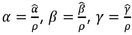
- the term ⁇ a f x d may be represented by ⁇
- the term ⁇ b f y d may be represented by ⁇
- the term 1 d a f x u 0 + b f x u 0 ⁇ c may be represented by ⁇ .
- Z ⁇ u + ⁇ v + ⁇ ⁇ ⁇ 1
- a multi-headed model is used, i.e., a neural network architecture including a plurality of heads and a common backbone/feature extractor as mentioned above.
- the pixel-based depth estimator head 4 of the model/network architecture 1, generates a first estimate of depth, D i , by decomposing the mapping f ⁇ : I ( u, v ) ⁇ D ( u, v ) into sub-tasks: a first sub-task determines a dense plane coefficient representation, C ( u , v ), for the image, and a second sub-task applies Equation (4) above to convert the plane coefficient representation, C ( u , v ), into the initial depth prediction D i .
- a ground-truth depth map D * is available for each image I in the training data set and supervision may be applied to the initial depth predictions D i using Equation (1) above.
- Fig.2 illustrates schematically a preferred embodiment of the pixel-based depth estimator head 4, incorporating a plane coefficient predictor 42 trained and configured to perform the above-mentioned first sub-task to predict the plane coefficients C ( u , v ), and a plane-coefficient-to-depth convertor 44 trained and configured to perform the above-mentioned second sub-task to generate the initial estimate of depth, D i .
- Predicting the plane coefficients C ( u , v ) as an intermediate output does not give an immediate advantage compared to directly predicting the depth.
- two pixels that depict the same 3D plane have the same parameters C ( u , v ), but generally a different depth. This fact is exploited by the second head 6 of the network, described below, which predicts depth by selectively bootstrapping the plane coefficients from a seed pixel.
- the plane coefficients predicted in the pixel-based depth estimator 4 are supplied to seed-pixel-based depth estimator 6.
- the seed-pixel-based depth estimator 6 of the model/network architecture generates a second estimate of depth, D s , by considering "seed pixels" which, within the 3D scene, are located on the same plane as a pixel of interest. The reasoning behind this approach is explained below.
- the seed-pixel-based depth estimator 6 is trained to determine which pixels to use as seed pixels and over which region in the image a given seed pixel may be used to estimate depth.
- the offset vector field decoder in the neural network architecture is trained to predict a dense offset vector field o( u , v ). Then the predicted offset vector field is used to resample the plane coefficients generated by the plane coefficient decoder 4, as indicated in equation (5) below.
- C S p C p + o p using bilinear interpolation to handle fractional offsets.
- D S u v h C S u v , u , v based on the seed locations. This process allows the network to bootstrap the depth from the seed pixel.
- Fig.3 illustrates schematically a preferred embodiment of the seed-pixel-based depth estimator 6, incorporating an offset-vector-field predictor 62, a plane coefficient resampling unit 64 and a plane-coefficient to depth convertor 66.
- the offset-vector-field predictor 62 is trained and configured to predict the dense offset vector field o( u , v ).
- the offset vector predicted for a pixel by the offset-field-vector predictor 62 tends to point towards a seed pixel with which it shares the same plane coefficients. this point is illustrated by Fig.4 .
- Fig.4 relates to an image from the NYU Depth-v2 dataset, this dataset being described in " Indoor segmentation and support inference from rgbd images" by Nathan Silberman et al, in European Conference on Computer Vision, 2012 ).
- the top picture in Fig.4 illustrates the true locations of planes in the 3D scene represented by the image.
- the bottom picture in Fig.4 illustrates the offset vector field predicted in respect of this image by the offset-vector-field predictor 62 in a trained depth-estimation system 1 according to the present embodiment of the invention.
- the plane coefficient resampling unit 64 is trained and configured to resample the plane coefficients generated in the first sub-task performed by the plane coefficient decoder 4, e.g., the plane coefficients generated by the plane coefficient predictor 42 illustrated in Fig.2 , using the predicted offset vectors generated by the offset-vector-field predictor 62.
- the plane-coefficient to depth convertor 66 is trained and configured to compute the second depth prediction D s . according to Equation (6) above.
- the fusion unit 8 combines the initial depth prediction D i generated by the pixel-based depth estimator 4 and the depth prediction, D s , generated by the seed-pixel-based depth estimator 6 in an adaptive manner.
- the fusion unit 8 outputs depth estimates D f that are weighted averages of the initial depth prediction D i generated by the pixel-based depth estimator 4 and the depth prediction, D s , generated by the seed-pixel-based depth estimator 6.
- the fusion unit 8 is configured to generate the final output depth estimates D f based on a confidence parameter which quantifies the probability that the piecewise planarity prior is valid.
- the seed-pixel-based depth estimator 6 includes a confidence-map generator 68, as illustrated in dashed lines in Fig.3 .
- the seed-pixel-based depth estimator 6 is trained and configured so that the confidence-map generator 68 generates a confidence map F( u,v ) ⁇ [0,1] which indicates, for each position ( u, v ) a prediction indicating the confidence of the model in using the predicted seed pixels for estimating depth via D s .
- the fusion unit 8 then adaptively fuses D i and D s according to Equation (7) below.
- D f u v F u v D s u v + 1 ⁇ F u v D i u v
- the seed-pixel-based depth estimator 6 is configured to refine the offset vector field by cascading the offset vectors multiple times before the plane coefficient maps are resampled by the plane coefficient resampling unit 64. For example, a single cascading step samples the position p + o(p) + o(p + o(p)). It may be considered that, in such embodiments, the seed-pixel-based depth estimator 6 includes an offset-vector-field refining unit 64. The motivation for this cascaded refinement is that seed pixels within the same planar region should converge to the center of the region, which helps accumulate information from more pixels in predicting the plane coefficients of the region as a whole. Cascading the offsets does not cause a problem in regard to depth that are made in respect of pixels without a reliable seed pixel, because the fusion unit 8 is configured to apply a low weight to the relevant depth prediction D s .
- Figs. 1-3 operate in respective training and production phases.
- the description above focuses on the functioning after training, i.e., during the production phase. Further details regarding the training phase shall be given below.
- the convolutional neural network structures in question are trained in a supervised learning process which trains the system end-to-end as a whole, while seeking to minimize a loss function.
- the loss function used in optimizing the system to predict values of D i , D s and D f is defined by Equation (8) below.
- L depth L D f , D * + ⁇ L D s , D * + ⁇ L D i , D * with ⁇ and ⁇ being hyperparameters.
- This loss function encourages (i) the pixel-based depth estimator head 4 to output a representation that is accurate across all pixels even when they have a high confidence value and (ii) the seed-pixel-based depth estimator head 6 to learn high confidence values for pixels for which the planarity prior holds and low confidence values for the converse.
- the model is not supervised directly on the offsets.
- the seed-pixel-based depth estimator could simply predict zero offsets everywhere and valid predictions D s and D f would still be produced, which would then be identical to D i .
- This unwanted behavior is avoided in practice thanks to the fact that the initial predictions D i are erroneously smoothed near depth boundaries, due to the regularity of the mapping f ⁇ for the case of neural networks.
- predicting a non-zero offset that points away from the boundary yields a lower value for L depth , because such an offset uses a seed pixel for D s which is further from the boundary and suffers from smaller error owing to smoothing.
- these non-zero offsets are propagated from the boundaries to the inner parts of regions with smooth depth, helping the network to predict non-trivial offsets.
- the supervised learning that is applied to the depth-estimation system during the training phase makes use of a composite loss function in which L depth is only one component.
- the preferred loss function L total includes an additional patch-level mean plane loss, L MPL , which is complementary to the previous components and contributes independently to learning regular depth maps.
- L MPL additional patch-level mean plane loss
- the formulation of the patch-level mean plane loss is based on the assumption that, given a pixel coordinate, the neighboring pixels to this pixel should lie on the same plane in the 3D space. So, the normal n of this plane should satisfy an overdetermined system of linear equations.
- ground-truth depth maps are usually captured by consumer-level sensors with noisy measurements and limited precision, and so use of the above regime for local fitting of normals does not guarantee that the true optimal solution is obtained.
- Equation (9) A T A ⁇ 1 A T b ⁇ ( A T A ⁇ 1 A T b ⁇ 2
- Equation (10) Given Equation (9), it can be seen that the mean patch loss, L MPL , directly affects the depth of all points inside the patch via A.
- the depth-estimation system and method estimate depth by selectively combining depth from each pixel and from its corresponding seed pixel.
- This formulation works because a common representation is used which captures pixelwise depth as well as planarity information.
- This is achieved by using a plane coefficient representation, which allows the supervision of the network to be performed only with depth.
- the main advantage of the plane coefficient representation is that the depth of a pixel in the image can be directly computed by the plane coefficients of a different pixel, under the assumption that the two pixels are on the same plane. This advantage forms the basis of the above-mentioned planarity prior and the selective planar depth bootstrapping using seed pixels.
- the embodiments of the invention do not make an explicit prediction of planes but rather uses a plane coefficient representation as an appropriate output space for defining interactions between pixels based on planarity priors.
- the depth predictions from the two heads are fused adaptively, notably based on a confidence map, in order to down-weigh the offset-based prediction and rely primarily on the basic depth prediction in regions where the piecewise planarity prior is not valid, e.g., on parts of the scene with highfrequency structures.
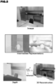
- supervision on the offsets and confidence map is applied implicitly, by virtue of the supervision of the fused depth prediction. Thanks to using seed pixels for prediction, the model implicitly learns to group pixels based on their membership in smooth regions of the depth map. This helps preserve sharp depth discontinuities, as illustrated in Fig.5 .
- Fig.5 illustrates a real-world scene in which there is a high degree of regularity.
- Fig.5 also shows intermediate representations of the scene that may be considered to be generated within systems according to the invention, as well as a representation of the final depth map D f ( u,v ) generated by the system and a 3D reconstruction based on that final depth map. It can be seen that the system and method according to the invention predicts high-quality depth maps which include sharp edges at occlusion boundaries and which yield consistent 3D reconstructions.
- the neural network structure 10 includes a single encoder 2 and each of the pixel-based depth estimator 4 and the seed-pixel-based depth estimator 6 comprises a respective decoder.
- the encoder 2 is based around a feed-forward residual network backbone configured to generate feature maps at multiple scales.
- Fig.6 illustrates the general structure of a preferred implementation 20 of encoder coupled to a first decoder (which generally represents offset-vector-field decoder 62, or the combination of offset-vector-field decoder 62 with confidence map generator 68), and a second decoder (which generally represents plane coefficient decoder 42).
- the general form of the neural network structure illustrated in Fig.6 is adapted from the deep neural network structure described by Ke Xian, Chunhua Shen, Zhiguo Cao, Hao Lu, Yang Xiao, Ruibo Li, and Zhenbo Luo in "Monocular relative depth perception with web stereo data supervision", see Proceedings of the IEEE Conference on Computer Vision and Pattern Recognition (CVPR), June 2018 , the entire contents of which are incorporated herein by reference.
- the encoder 20 includes a feed-forward neural network backbone which is a convolutional neural network (CNN) structure implemented as a ResNet.
- CNN convolutional neural network
- the convolution layers and pooling layers are arranged to generate feature maps at successively larger scales and may be considered to form a series of feature map generators 25.
- the input image data has dimensions 384x384 and the successive feature map generators generate feature maps at 96x96, 48x48, 24x24 and 12x12, which are labelled, respectively, as feature_map 1 , feature_map 2 , feature_map 3 , and feature_map 4 in Fig.6 .
- the decoders make use of three types of modules: feature fusion modules 100, residual convolution modules 140 and adaptive output modules 110 described below.
- a feature fusion module 100 uses a first residual convolution block 140a to transform the skip connection feature map from the ResNet encoder 20.
- the output of the first residual convolution block 140a is fused with the output of the preceding feature fusion block 100 (or the output of up-sampling unit 90 of Fig.6 , as applicable) using a summation operation.
- the feature maps are up-sampled to match the resolution of the next layer's input.
- a residual convolution module 140 is a series of two units of ELU (exponential linear unit) and 3 ⁇ 3 convolution operations arranged to merge the output of a preceding decoder feature map output with a preceding feature fusion module output.
- ELU exposure linear unit
- the adaptive output module 110 which is applied at the last stage to get the final output of the general decoder structure 70 shown in Fig.6 , consists of two 3 ⁇ 3 convolution operations followed by up-sampling.
- the last layer of the decoder head is modified, compared to the adaptive output unit 110 illustrated in Figs.6 and 9 , to output 4-channels for each planar coefficient instead of single channel depth.
- the last layer of the decoder head is modified, compared to the adaptive output unit 110 illustrated in Figs.6 and 9 , to output 3-channels, i.e., two channels for the offset vector field and one for the confidence.
- the offset vector field is restricted by tanh layers and the confidence is generated through a sigmoid layer.
- the plane coefficient predictor 42 incorporates a guidance module.
- Fig.10 illustrates a preferred embodiment of a plane coefficient predictor 420 incorporating a plane coefficient guidance module 200.
- each decoder block 25 is passed through the plane coefficient guidance module 200 to generate 4 channels of plane coefficients.
- the output size of the guidance module 200 is up sampled to match the input size of last decoder layer.
- these plane coefficients from each scale are converted into depth. All these depth maps are concatenated with feature map of the previous decoder layer passed to the last decoder layer.
- Fig.11 illustrates a preferred embodiment of the pixel-based depth estimator 4, in which a decoder 42a of the type illustrated in Fig.6 , is used in association with a plane coefficient guidance module 200.
- the output of each of the feature fusion units 100 passes through the plane coefficient guidance module 200 (as shown in Fig 10 ).
- the concatenation of all these outputs passes through the adaptive output unit 110 to yield the pixel-based depth estimate Di.
- the adaptive output unit 110 includes a combining module 112 as well as a convolution module 114.
- depth-estimation systems are generally implemented digitally, that is, by implementing in software the neural network structures discussed herein, their combinations and training. Accordingly, the present invention provides a computer system programmed to implement the depth-estimation system described above, according to any of its embodiments. In a similar way, the present invention provides a non-transitory computer-readable medium containing instructions which, when executed by a computer system, cause the computer system to implement a depth-estimation system or a depth-estimation method as described above, according to any of their embodiments.
- P3Depth the depth-estimation system 1 was implemented using a pixel-based depth estimator according to the embodiment illustrated in Fig.2 , and a seed-pixel-based depth estimator according to the embodiment illustrated in Fig.3 (including the confidence-map generator 68), and the fusion unit was configured to adaptively merge the depth estimates D i and D s on the basis of the confidence map F(u, v ) according to equation (7) above.
- the P3depth embodiment of the invention used in the experimental studies employed an encoder/decoder structure as described above in connection with Figs.6 to 9 , with the last layer of the plane coefficient decoder 42 modified to output 4-channels for each planar coefficient instead of single channel depth, and the last layer of the offset vector field decoder 62 modified to output 3-channels, i.e., two channels for the offset vector field and one for the confidence.
- the main datasets used in the training and testing of the P3Depth embodiment of the invention were the NYU Depth-v2 and KITTI datasets.
- the other four datasets were used for zero-shot testing, that is, evaluating the P3Depth embodiment using datasets that had not been used during the training (so as to determine how well the trained network architecture generalized to inputs different from those used during the training).
- the resolution of all images was reduced to 640 ⁇ 480.
- the NYU Depth-v2 dataset consists of 464 indoor scenes of size 640 ⁇ 480. In the experiments, these scenes were split into 249 scenes for training and 215 for testing, using the split described by Jin Han Lee et al op. cit., July 2019, and the test set was based on the approach described by David Eigen et al, op. cit.
- KITTI is dataset developed in view of autonomous driving and consists of 61 outdoor scenes of different types. In the experiments, these scenes were split into 32 scenes for training and 29 for testing, using the split described by Eigen et al op. cit., and by Garg et al in "Unsupervised CNN for single view depth estimation: Geometry to the rescue” in European Conference on Computer Vision (ECCV), 2016 .
- a number of evaluation metrics were used, notably various depth estimation metrics that are standard in this field.
- the following evaluation metrics were used: root mean square error (RMSE) and its log variant (RMSElog), Log10 error, absolute (A.Rel) and squared (S.rel) mean relative error, and the percentage of inlier pixels with ⁇ .
- the maximum depth for KITTI was set to 50m and 80m for the Garg and Eigen splits respectively.
- the maximum depth was set to 10m as per the Eigen split.
- Zero-shot transfer was performed by using a model trained on NYU Depth-v2 without additional fine-tuning. The maximum depth for this task was set to 10m across all four test datasets. In all evaluations, the predicted depth was rescaled so that its median matched that of the ground truth, as per standard practice.
- Table 2 summarizes the values of various depth estimation metrics that were generated in respect of depth estimations produced by the example embodiment of the invention and by various comparative examples, in experiments performed by training all the compared systems using the NYU Depth-v2 dataset. The comparison was performed on the Eigen split.
- nF indicates the number of frames and ⁇ indicates self-supervised methods.
- NYU Depth-v2 is the major indoor depth benchmark. It can be seen from Table 2 that, when all methods were tested and trained using the NYU Depth-v2 dataset, the depth estimation performance of the P3Depth embodiment of the invention evaluated in terms of the metric ⁇ 3 matched that of the best-performing of the other methods (Huynh et al [22]). On all of the other five standard metrics, the depth estimation performance of the P3Depth embodiment of the invention was better than that of any of the other examined methods, achieving a superior relative performance gain of 9.18% in RMSE and 3.7% in A.Rel, while also improving and ⁇ 1 by 1.1%. This improvement in performance indicates that without using ground-truth planes as supervision, P3Depth learns an implicit representation of the planes which can benefit the overall depth estimation capability of the network.
- Fig. 12 illustrates the high-quality depth predictions generated by the P3Depth embodiment of the invention in comparison with state-of-the-art methods using the same examples as in Yin et al, op. cit.
- the comparative examples show depth estimates generated by the DORN method (described by Fu et al, op. cit.), the VNL method (described by Yin et al, op. cit.), and the BTS method (described by Lee et al, op. cit.).
- the ground truth (GT) depth values are illustrated in the bottom row of images in Fig.12 .
- the surfaces which fit the piece-wise planar assumption used in the invention such as a table, a cupboard, and even smaller objects, e.g., computer screens, photo frames etc. have consistent depth predictions with sharp details when the depth estimates are produced by the P3Depth embodiment of the invention as compared to the state-of-the-art methods.
- the P3Depth embodiment of the invention generates superior visual results.
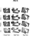
- the P3Depth embodiment of the invention excels especially on man-made regular structures in the indoor scenes. What is more, the predicted depth maps produce 3D reconstructions (front view, side view and top view) which are consistent with ground-truth point clouds and preserve the structure of the scene better than competing methods, as illustrated in Fig. 13 .
- Table 3 summarizes the values of various depth estimation metrics that were generated in respect of depth estimations produced by the example embodiment of the invention and by various comparative examples, in experiments performed by training all the compared systems using the KITTI dataset. The comparison was performed on the Eigen split and on the Garg split as indicated in the table. TABLE 3 Method A.Rel S.Rel RMSE RMSE log ⁇ 1 ⁇ 2 ⁇ 3 Lower values are better Higher values are better Garg split.
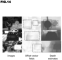
- the system/method according to the present embodiment is comparable to state of the art as it generally ranks second and it is outperformed only by the method according to Lee et al, op. cit. It is understandable that the ranking is slightly lower on the Eigen split as compared to the Garg split, given that distant parts of the scene get projected to smaller regions and thus the extent of the respective smooth pieces of the depth map is also smaller, making it more difficult to predict a correct offset. Overall, the method is able to handle planar objects well even in variable lighting conditions. The latter point is illustrated by Fig. 14 .
- Fig.14 illustrates three images from the KITTI dataset in which lighting conditions vary, along with the offset-vector fields and the depth estimates. generated for these images by the method/system according to the present embodiment.
- the sign board in the bottom image is brightly lit and the car in the middle image is badly lit, the method is able to detect the regularity of the object surface and predict consistent depth.
- the supervised method for monocular depth estimation leverages local planar information in the 3D scene in order to predict consistent depth values across smooth parts of the scene.
- the method uses a plane coefficient representation for depth, which enables to share information from seed locations and improve the predicted depth.
- the method implicitly learns to predict the offsets to these seed locations and to weigh the depth obtained from them adaptively according to confidence.
- the method was empirically validated on the major indoor and outdoor benchmarks for monocular depth estimation and sets the new state of the art among supervised approaches.
Landscapes
- Engineering & Computer Science (AREA)
- Physics & Mathematics (AREA)
- Theoretical Computer Science (AREA)
- General Physics & Mathematics (AREA)
- General Health & Medical Sciences (AREA)
- General Engineering & Computer Science (AREA)
- Biophysics (AREA)
- Computational Linguistics (AREA)
- Data Mining & Analysis (AREA)
- Evolutionary Computation (AREA)
- Artificial Intelligence (AREA)
- Molecular Biology (AREA)
- Computing Systems (AREA)
- Biomedical Technology (AREA)
- Life Sciences & Earth Sciences (AREA)
- Mathematical Physics (AREA)
- Software Systems (AREA)
- Health & Medical Sciences (AREA)
- Computer Vision & Pattern Recognition (AREA)
- Image Analysis (AREA)
- Image Processing (AREA)
Abstract
Description
- The present invention relates to the field of image processing and, in particular, to the estimation of depth of three-dimensional (3D) points represented by pixels in images. More particularly, the invention relates to depth estimation systems and computer-implemented depth estimation methods that determine depth based on monocular data (i.e., data obtained from a single camera/viewpoint, as opposed to stereo image data).
- Depth estimation is a fundamental problem in computer vision. In general, it involves determining a value for the perpendicular coordinate of the 3D point depicted at a pixel of an image. The determined value may be considered to be an estimate or prediction of the true depth of the relevant 3D point. Typically, the processed image data corresponds to a still image or to a frame of a video.
- Depth-estimation is important in a wide range of applications, including robotics and autonomous cars, and forms part of preliminary processing that enables an automatic system to interpret a scene and implement downstream tasks (e.g., to drive actuators and motors so that a robotic hand can grasp an object, to control steering in an autonomous vehicle so as to avoid an obstacle, and so on). Indeed, there is experimental evidence that, together with semantic segmentation, depth is the most vital vision-level cue for automatic systems to execute actions.
- The present invention addresses depth estimation in the context where the source image data is monocular (i.e., generated by a single imaging device/camera). Monocular depth estimation involves the challenge of scale ambiguity, as the same input image can be generated by infinitely many 3D scenes.
- The current trend in performing monocular depth estimation involves use of fully convolutional neural networks that output a dense depth prediction (i.e., a prediction of depth for each pixel in the image) and are trained to perform an end-to-end mapping from image data to depth maps, either with standard supervision on depth or with self-supervision by using the predicted depth to reconstruct neighbouring views of the scene. Most supervised approaches train the network using a loss function that is computed independently for each pixel, i.e., predictions at different pixels are treated separately. Such approaches ignore the high degree of regularity that exists in real-
world 3D scenes, which generally yield depth maps that are piecewise smooth (i.e., real-world scenes tend to contain many regions within which neighbouring pixels have the same or similar depths). - Some known systems seek to leverage the fact that scenes often contain regions representing 3D points that are located on a common plane. Planes are the local first-order Taylor approximation for locally differentiable depth maps and they are easy to parameterize using three independent coefficients. Once a pixel is associated with a plane, its depth can be recovered from the position of the pixel and the coefficients of the associated plane. Some known systems explicitly predict the planes in a 3D scene represented by the image data. However, the accuracy of depth predictions made using known approaches is not as high as desired.
- The present invention has been made in the light of the above problems.
- The present invention provides a depth-estimation system to estimate depth of three-dimensional points corresponding to pixels in an image representing a three-dimensional scene, the depth-estimation system comprising:
- a trained neural network architecture including a pixel-based depth estimator and a seed-pixel-based depth estimator parallel to the pixel-based depth estimator,
- the pixel-based depth estimator comprising a plane coefficient detector configured to receive feature data of said image, to generate an intermediate output comprising plane coefficients of respective pixels in the image, and to generate a first depth estimate by converting the plane coefficients to depth values, and
- the seed-pixel-based depth estimator comprising an offset-vector-field detector configured to receive feature data of said image, to generate an intermediate output comprising offset vectors between target pixels and seed pixels on planes in the three-dimensional scene represented by the image, to resample the plane coefficients produced by the plane coefficient detector using the offset vector field, and to generate a second depth estimate by converting the resampled plane coefficients to depth values; and
- a fusion unit configured to receive, and to combine, the first and second depth estimates to produce a final depth estimate for output.
- The monocular depth-estimation system according to the invention achieves depth-estimation performance which exceeds that of the state-of-the-art monocular depth-estimation systems, as demonstrated in experimental studies discussed below.
- In certain embodiments of the invention the offset-vector-field detector is configured to generate a confidence map indicative of a level of confidence that a seed pixel is in the same plane as a target pixel, and to supply the confidence map to the fusion unit; and the fusion unit is configured to weight the first and second depth estimates based on confidence values in the confidence map generated by the offset vector field generator. This approach ensures that the depth estimate produced for a given pixel based on consideration of seed pixels influences the final depth estimate for this pixel primarily when there is a high degree of certainty that the seed pixel and target pixel truly lie on a common plane in the scene.
- The offset-vector-field detector is configured to predict the offset o(p) = q - p between each pixel p and a seed pixel q on the same plane as pixel p in the scene. In certain preferred embodiments of the invention the seed-pixel-based depth estimator is configured to refine the offset vector field by cascading the offset vectors multiple times before resampling the plane coefficients, wherein a single cascading step consists in sampling the position p + o(p) + o(p + o(p)). Experimental studies have shown that the depth estimation accuracy improves in the case where the offsets are cascaded.
- In certain embodiments of the invention the neural network architecture has been trained in a supervised end-to-end training process which minimizes a loss function Ldepth defined according to the equation below:
 (Df ,D∗ ) is a loss function that penalizes deviations between the final depth estimate produced by the fusion unit and the ground truth, L(Ds ,D∗ ) is a loss function that penalizes deviations between the second depth estimate produced by the seed-pixel-based depth estimator and the ground truth, L(Di ,D∗ ) is a loss function that penalizes deviations between the first depth estimate produced by the pixel-based depth estimator and the ground truth, and λ and µ are hyperparameters.
- The supervised end-to-end training process may seek to minimize a total loss function Ltotal which includes a mean patch loss LMPL additional to Ldepth where the mean patch loss LMPL is defined according to the equation below:

- Certain embodiments of the invention further comprise a guidance module.
- The present invention further provides a method of training the above-mentioned depth-estimation system, the training method comprising:
inputting, to the neural network architecture of the depth-estimation system, feature data of images for which ground truth depth values are known, and training the neural network architecture to minimize a loss function Ldepth defined according to the equation below:
- Advantageously, the training may seek to minimize a total loss function Ltotal which includes a mean patch loss LMPL additional to Ldepth where the mean patch loss LMPL is defined according to the equation below:

- The above-recited training method produces a trained depth-estimation system as mentioned above, with its concomitant advantages.
- The present invention still further provides a computer-implemented method of estimating depth of three-dimensional points corresponding to pixels in an image representing a three-dimensional scene, the method comprising:
- processing feature data of said image in first and second parallel paths; in the first parallel path:
- generating an intermediate output comprising plane coefficients of respective pixels in the image, and
- generating a first depth estimate by converting the plane coefficients to depth values;
- in the second parallel path:
- generating an intermediate output comprising predicted offset vectors between target pixels and seed pixels on planes in the three-dimensional scene represented by the image,
- using the predicted offset vectors to resample the plane coefficients produced in the first parallel path, and
- generating a second depth estimate by converting the resampled plane coefficients to depth values; and
- The above-mentioned method, may further comprise, in the second parallel path, the generating of a confidence map indicative of a level of confidence that a seed pixel is in the same plane as a target pixel, and the combining may comprise weighting the first and second depth estimates based on confidence values in the confidence map.
- In the above-mentioned method, the generating of the offset vectors predicts the offset o(p) = q - p between each pixel p and a seed pixel q on the same plane as pixel p in the scene. The offset vector field may be refined by cascading the offset vectors multiple times before the plane coefficients are resampled to generate the second depth estimate, wherein a single cascading step consists in sampling the position p + o(p) + o(p + o(p)). As mentioned above, the accuracy of the depth estimates is further improved in the case of cascading the offsets.
- Further features and advantages of the present invention will become apparent from the following description of certain embodiments thereof, given by way of illustration only, not limitation, with reference to the accompanying drawings in which:
-
Figure 1 illustrates, schematically, the main components of a depth-estimation system according to a generic embodiment of the present invention; -
Figure 2 illustrates, schematically, an example of a pixel-based depth estimator that may be used in the system according toFig.1 ; -
Figure 3 illustrates, schematically, an example of seed-pixel-based depth estimator that may be used in the system according toFig.1 ; -
Figure 4 illustrates ground truth in regard to planes present in a 3D scene represented by an example image as well as an offset-vector field generated by an embodiment of the invention in relation to the same image; -
Figure 5 shows images representing outputs generated at different steps of a method according to an example embodiment of the invention, illustrating that depth-estimation methods and systems according to the invention enable sharp depth discontinuities to be detected, -
Figure 6 represents schematically a general encoder-decoder structure that may be used in embodiments of the invention; -
Figure 7 represents schematically a feature fusion module that may be used in the structure illustrated inFig.6 ; -
Figure 8 represents schematically a residual convolution module that may be used in the structure illustrated inFig.6 ; -
Figure 9 represents schematically an adaptive output module that may be used in the structure illustrated inFig.6 ; -
Figure 10 represents schematically a plane coefficient decoder incorporating a plane coefficient guidance module, that may be used in certain embodiments of the invention; -
Figure 11 represents schematically a preferred embodiment of the pixel-based depth estimator, incorporating a plane coefficient guidance module; -
Figure 12 illustrates depth estimates produced for four example images by an embodiment of the invention called P3Depth, as well as depth estimates according to three comparative example techniques, and ground truth in regard to depth of points in the represented 3D scene; -
Figure 13 shows front, side and top views reconstructed from depth estimates produced for an example image by an embodiment of the invention called P3Depth, as well as depth estimates according to two comparative example techniques, and ground truth in regard to the respective views; and -
Figure 14 shows, in respect of three example images, qualitative results obtained when the P3depth embodiment of the invention predicts offset vector fields and estimates depth. - Monocular depth-estimation systems according to various embodiments of the invention, and computer-implemented methods of estimating depth in monocular images according to various embodiments of the invention will now be described with reference to
Figs. 1 to 14 . - The invention proposes a new CNN-based architecture configured to perform depth estimation. Based on knowledge about the high regularity of real 3D scenes, the CNN architecture according to the invention is trained to selectively leverage information from coplanar pixels to improve the depth predictions. In particular, the technique is based on a piecewise planarity prior (base assumption) which states that for each pixel, there is a seed pixel which shares the same planar 3D surface with the former.
- Motivated by this piecewise planarity prior, the invention proposes a CNN-based architecture comprising a novel combination of two heads, as illustrated in
Fig.1 . One head is a pixel-based depth estimator and the other head is a seed-pixel-base depth estimator. The two heads of the network share a common encoder and have separate decoders, as shown inFig.1 and as discussed below with reference toFigs.6-10 . -
Fig.1 is a schematic representation of main modules comprised in the depth-estimation system 1 according to a first, generic embodiment of the invention. A monocular image stream is input to the common encoder, i.e.,feature extractor 2, and the feature data from the common encoder is processed in parallel by the pixel-baseddepth estimator backbone 4, which includes functionality to estimate plane coefficients, and a seed-pixel-baseddepth estimator backbone 6, which includes functionality to generate an offset-vector field. The input data stream represents a scene imaged by an image-capture device such as a video camera. The stream may be a live feed output by a video camera (e.g., a video camera mounted on a vehicle), but the invention is not particularly limited having regard to the source of the image data input to the depth-estimation system 1 and it is to be understood that the system can operate not only on live data but also on recorded data. - In preferred embodiments of the invention the
feature extractor 2 is a neural network structure, for example, a residual network structure and is trained to extract salient features from the initial image data. - The pixel-based
depth estimator 4 is trained to generate a first depth estimate, Di , based on pixel-level plane coefficients, and to output the initial depth estimate Di to afusion unit 8. The seed-pixel-baseddepth estimator 6 is trained to generate a dense offset vector field that identifies the positions of seed pixels and to use the plane coefficients of the seed pixels to produce a second depth estimate, Ds, for each position. The seed-pixel-baseddepth estimator 6 is arranged to output the second depth estimate, Ds, to thefusion unit 8. Each of the pixel-baseddepth estimator 4 and the seed-pixel-baseddepth estimator 6 comprises trained convolutional neural network (CNN) structure, as shall be described below. - The
fusion unit 8 is configured to output a final depth estimate, Df, based on a combination of the first and second estimates Di and Ds. Thefusion unit 8 is configured to adaptively combine the first and second depth estimates Di and Ds and, in preferred embodiments of the invention, the weighting of the first and second depth estimates is based on a learned "confidence" parameter. - In preferred embodiments of the invention the entire architecture is trained end-to end thanks to the differentiability of the proposed component modules, and it learns to predict regular depth maps, with sharp edges at occlusion boundaries. In preferred embodiments of the invention, the architecture is trained using supervised learning during which ground truth depth values are available for the pixels in the input image data of the training data set.
- A description will now be given of the functions performed by the above-mentioned components of the depth-
estimation system 1, together with description of certain preferred embodiments of those components. - In order to be able to perform monocular depth estimation, a machine learning architecture (e.g., a neural network architecture) needs to learn a dense mapping fθ : I(u,v) → D(u,v), where I is the input image with spatial dimensions H × W, D is the corresponding depth map of the same resolution, ( u, v) are pixel coordinates in the image space, and θ are the parameters of the mapping f . In the case of supervised learning, a ground-truth depth map D* is available for each image I at training time. During training, the parameters θ are optimized such that the function fθ minimizes the difference between the predicted depth and the ground-truth depth over the training set T.
- This can be formalized as shown in Equation (1) below:

- Furthermore, each pixel can be back-projected to the 3D space represented by the image, given a depth map D and certain parameters of the camera generating the image data. More particularly, using the pinhole camera model and given the focal lengths ( fx ,fy ) and the principal point ( u0, v0 ), every pixel p = (u,v) T may be mapped to a 3D point P = (X,Y,Z) T according to Equation (2) below

- Embodiments of the present invention make use of a plane coefficient representation for depth, before generating the desired depth map. Let it be supposed that the back-projected 3D point P corresponds to a planar part of the 3D scene represented by the image. The equation of the associated plane in the point-normal form can be written as n • P + d = 0, where n = (a,b,c) T is the normal vector to the plane and -d is the distance of the plane from the origin (0,0,0) of the 3D coordinate system employed in representing the points in the 3D scene.
- Substituting the coordinates of point P represented in Equation (2) above into the point normal equation produces Equation (3) below defining the inverse depth of point P.

- Thus, for image regions that depict planar 3D surfaces, the inverse depth is an affine function of pixel position, where the coefficients encode both the camera intrinsics (focal lengths and the principal point) and the 3D plane. The term



- In embodiments of the invention, a multi-headed model is used, i.e., a neural network architecture including a plurality of heads and a common backbone/feature extractor as mentioned above. The pixel-based
depth estimator head 4 of the model/network architecture 1, generates a first estimate of depth, Di, by decomposing the mapping fθ : I(u, v) → D(u, v) into sub-tasks: a first sub-task determines a dense plane coefficient representation, C(u,v), for the image, and a second sub-task applies Equation (4) above to convert the plane coefficient representation, C(u,v), into the initial depth prediction Di. More formally, the mapping fθ : I(u,v) → D(u,v) is treated as a composition fθ = h ∘ (gθ,p), where gθ : I(u, v) → C(u, v) maps the input image to the plane coefficient representation, and h:(C(u, v), u, v) → Di (u, v) applies Equation (4) at each pixel. During the process of training the pixel-baseddepth estimator head 4, a ground-truth depth map D* is available for each image I in the training data set and supervision may be applied to the initial depth predictions Di using Equation (1) above. -
Fig.2 illustrates schematically a preferred embodiment of the pixel-baseddepth estimator head 4, incorporating aplane coefficient predictor 42 trained and configured to perform the above-mentioned first sub-task to predict the plane coefficients C(u,v), and a plane-coefficient-to-depth convertor 44 trained and configured to perform the above-mentioned second sub-task to generate the initial estimate of depth, Di. - Predicting the plane coefficients C(u,v) as an intermediate output does not give an immediate advantage compared to directly predicting the depth. However, two pixels that depict the same 3D plane have the same parameters C(u,v), but generally a different depth. This fact is exploited by the
second head 6 of the network, described below, which predicts depth by selectively bootstrapping the plane coefficients from a seed pixel. As indicated inFig.2 , the plane coefficients predicted in the pixel-baseddepth estimator 4 are supplied to seed-pixel-baseddepth estimator 6. - In embodiments of the present invention, the seed-pixel-based
depth estimator 6 of the model/network architecture generates a second estimate of depth, Ds , by considering "seed pixels" which, within the 3D scene, are located on the same plane as a pixel of interest. The reasoning behind this approach is explained below. - Let us assume we have one pixel p which belongs to a planar surface in 3D. By definition, every other pixel on this planar surface has the same C values (i.e., the same values of the plane coefficients). Thus, in an ideal world the neural network architecture would only have to predict C at one of these pixels, q, in order to be able to compute correctly the depth values of all other pixels on this planar surface. This pixel q can be interpreted as a "seed pixel" that describes the plane. This notion may be expressed in terms of a "piecewise planarity prior" according to
Definition 1 below:
Definition 1. (Piecewise planarity prior) For every pixel p with an associated 3D plane, there exists a seed pixel q in the neighbourhood of p which is also associated with the same plane as p. - However, it is not trivial to determine which pixel should be used as a seed pixel, especially as there generally will be multiple seed pixels that could be used in respect of a given pixel of interest. Moreover, there may be no seed pixel in respect of a given pixel of interest, i.e., if the pixel of interest does not lie on a plane in the scene. Thus, it is not trivial to determine the region in the image over which the depth should be bootstrapped from a given seed pixel.
- In embodiments of the present invention the seed-pixel-based
depth estimator 6 is trained to determine which pixels to use as seed pixels and over which region in the image a given seed pixel may be used to estimate depth. - On the assumption that the piecewise planarity prior according to
Definition 1 holds true, the task of depth prediction for pixel p can also be solved by identifying q. This may involve predicting the offset o(p) = q - p. The offset vector field decoder in the neural network architecture according to embodiments of the invention is trained to predict a dense offset vector field o(u,v). Then the predicted offset vector field is used to resample the plane coefficients generated by theplane coefficient decoder 4, as indicated in equation (5) below.
- Then, the resampled plane coefficients are used to compute a second depth prediction Ds . according to Equation (6) below.

-
Fig.3 illustrates schematically a preferred embodiment of the seed-pixel-baseddepth estimator 6, incorporating an offset-vector-field predictor 62, a planecoefficient resampling unit 64 and a plane-coefficient todepth convertor 66. The offset-vector-field predictor 62 is trained and configured to predict the dense offset vector field o(u,v). The offset vector predicted for a pixel by the offset-field-vector predictor 62 tends to point towards a seed pixel with which it shares the same plane coefficients. this point is illustrated byFig.4 . -
Fig.4 relates to an image from the NYU Depth-v2 dataset, this dataset being described in "Indoor segmentation and support inference from rgbd images" by Nathan Silberman et al, in European Conference on Computer Vision, 2012). The top picture inFig.4 illustrates the true locations of planes in the 3D scene represented by the image. The bottom picture inFig.4 illustrates the offset vector field predicted in respect of this image by the offset-vector-field predictor 62 in a trained depth-estimation system 1 according to the present embodiment of the invention. - The plane
coefficient resampling unit 64 is trained and configured to resample the plane coefficients generated in the first sub-task performed by theplane coefficient decoder 4, e.g., the plane coefficients generated by theplane coefficient predictor 42 illustrated inFig.2 , using the predicted offset vectors generated by the offset-vector-field predictor 62. The plane-coefficient todepth convertor 66 is trained and configured to compute the second depth prediction Ds . according to Equation (6) above. - As noted above, the piecewise planarity prior according to
Definition 1 is not always valid. So, at some locations, the initial depth prediction Di generated by theplane coefficient decoder 4 may be more accurate than the depth prediction, Ds , generated by the seed-pixel-baseddepth estimator 6. Accordingly, in embodiments of the invention thefusion unit 8 combines the initial depth prediction Di generated by the pixel-baseddepth estimator 4 and the depth prediction, Ds , generated by the seed-pixel-baseddepth estimator 6 in an adaptive manner. In particular, thefusion unit 8 outputs depth estimates Df that are weighted averages of the initial depth prediction Di generated by the pixel-baseddepth estimator 4 and the depth prediction, Ds , generated by the seed-pixel-baseddepth estimator 6. - In preferred embodiments of the invention, the
fusion unit 8 is configured to generate the final output depth estimates Df based on a confidence parameter which quantifies the probability that the piecewise planarity prior is valid. In a preferred embodiment of the invention, the seed-pixel-baseddepth estimator 6 includes a confidence-map generator 68, as illustrated in dashed lines inFig.3 . The seed-pixel-baseddepth estimator 6 is trained and configured so that the confidence-map generator 68 generates a confidence map F(u,v) ∈ [0,1] which indicates, for each position (u, v) a prediction indicating the confidence of the model in using the predicted seed pixels for estimating depth via Ds . Thefusion unit 8 then adaptively fuses Di and Ds according to Equation (7) below.
- In certain preferred embodiments of the invention, the seed-pixel-based
depth estimator 6 is configured to refine the offset vector field by cascading the offset vectors multiple times before the plane coefficient maps are resampled by the planecoefficient resampling unit 64. For example, a single cascading step samples the position p + o(p) + o(p + o(p)). It may be considered that, in such embodiments, the seed-pixel-baseddepth estimator 6 includes an offset-vector-field refining unit 64. The motivation for this cascaded refinement is that seed pixels within the same planar region should converge to the center of the region, which helps accumulate information from more pixels in predicting the plane coefficients of the region as a whole. Cascading the offsets does not cause a problem in regard to depth that are made in respect of pixels without a reliable seed pixel, because thefusion unit 8 is configured to apply a low weight to the relevant depth prediction Ds . - The system and components illustrated in
Figs. 1-3 operate in respective training and production phases. The description above focuses on the functioning after training, i.e., during the production phase. Further details regarding the training phase shall be given below. - During the training phase, the convolutional neural network structures in question are trained in a supervised learning process which trains the system end-to-end as a whole, while seeking to minimize a loss function. In certain embodiments of the invention, the loss function used in optimizing the system to predict values of Di, Ds and Df is defined by Equation (8) below.

- This loss function encourages (i) the pixel-based
depth estimator head 4 to output a representation that is accurate across all pixels even when they have a high confidence value and (ii) the seed-pixel-baseddepth estimator head 6 to learn high confidence values for pixels for which the planarity prior holds and low confidence values for the converse. - As the skilled person will understand, the model is not supervised directly on the offsets. In fact, in principle the seed-pixel-based depth estimator could simply predict zero offsets everywhere and valid predictions Ds and Df would still be produced, which would then be identical to Di. This unwanted behavior is avoided in practice thanks to the fact that the initial predictions Di are erroneously smoothed near depth boundaries, due to the regularity of the mapping fθ for the case of neural networks. As a result, for pixels on either side of a boundary, predicting a non-zero offset that points away from the boundary yields a lower value for Ldepth , because such an offset uses a seed pixel for Ds which is further from the boundary and suffers from smaller error owing to smoothing. Also due to regularity of the mapping that generates the offset vector field, these non-zero offsets are propagated from the boundaries to the inner parts of regions with smooth depth, helping the network to predict non-trivial offsets.
- Nevertheless, in preferred embodiments of the invention, to obtain improved performance, the supervised learning that is applied to the depth-estimation system during the training phase makes use of a composite loss function in which Ldepth is only one component. More particularly, the preferred loss function Ltotal includes an additional patch-level mean plane loss, LMPL , which is complementary to the previous components and contributes independently to learning regular depth maps. In other words:

- The formulation of the patch-level mean plane loss is based on the assumption that, given a pixel coordinate, the neighboring pixels to this pixel should lie on the same plane in the 3D space. So, the normal n of this plane should satisfy an overdetermined system of linear equations. However, ground-truth depth maps are usually captured by consumer-level sensors with noisy measurements and limited precision, and so use of the above regime for local fitting of normals does not guarantee that the true optimal solution is obtained.
- Nevertheless, depth measurements still contain comprehensive details about the structure of the scene. This information can be aggregated locally to enforce first-order consistency between the predicted and the ground-
truth 3D surface. Normals are one way in which this aggregation across patches can be performed. For an input patch, the corresponding normal n needs to satisfy
An = b, such that ||n||2 = 1, where n is a data matrix build by stacking the 3D points in the patch and b is a vector of ones. - The closed-form solution of this least-squares problem is represented by Equation (9) below.

- To compute the mean plane loss, surface normals are first estimated for all K non-overlapping patches in D and D∗ and then their difference is penalized via the mean loss function defined by Equation (10) below.

- It can be understood that the depth-estimation system and method according to preferred embodiments of the invention estimate depth by selectively combining depth from each pixel and from its corresponding seed pixel. This formulation works because a common representation is used which captures pixelwise depth as well as planarity information. This is achieved by using a plane coefficient representation, which allows the supervision of the network to be performed only with depth. The main advantage of the plane coefficient representation is that the depth of a pixel in the image can be directly computed by the plane coefficients of a different pixel, under the assumption that the two pixels are on the same plane. This advantage forms the basis of the above-mentioned planarity prior and the selective planar depth bootstrapping using seed pixels. It should be noted that the embodiments of the invention do not make an explicit prediction of planes but rather uses a plane coefficient representation as an appropriate output space for defining interactions between pixels based on planarity priors.
- In the depth-estimation system and method according to preferred embodiments of the invention the depth predictions from the two heads are fused adaptively, notably based on a confidence map, in order to down-weigh the offset-based prediction and rely primarily on the basic depth prediction in regions where the piecewise planarity prior is not valid, e.g., on parts of the scene with highfrequency structures. During training of the system, supervision on the offsets and confidence map is applied implicitly, by virtue of the supervision of the fused depth prediction. Thanks to using seed pixels for prediction, the model implicitly learns to group pixels based on their membership in smooth regions of the depth map. This helps preserve sharp depth discontinuities, as illustrated in
Fig.5 . -
Fig.5 illustrates a real-world scene in which there is a high degree of regularity.Fig.5 also shows intermediate representations of the scene that may be considered to be generated within systems according to the invention, as well as a representation of the final depth map Df (u,v) generated by the system and a 3D reconstruction based on that final depth map. It can be seen that the system and method according to the invention predicts high-quality depth maps which include sharp edges at occlusion boundaries and which yield consistent 3D reconstructions. - As mentioned above, the
neural network structure 10 includes asingle encoder 2 and each of the pixel-baseddepth estimator 4 and the seed-pixel-baseddepth estimator 6 comprises a respective decoder. In preferred embodiments of the invention, theencoder 2 is based around a feed-forward residual network backbone configured to generate feature maps at multiple scales.Fig.6 illustrates the general structure of apreferred implementation 20 of encoder coupled to a first decoder (which generally represents offset-vector-field decoder 62, or the combination of offset-vector-field decoder 62 with confidence map generator 68), and a second decoder (which generally represents plane coefficient decoder 42). The general form of the neural network structure illustrated inFig.6 is adapted from the deep neural network structure described by Ke Xian, Chunhua Shen, Zhiguo Cao, Hao Lu, Yang Xiao, Ruibo Li, and Zhenbo Luo in "Monocular relative depth perception with web stereo data supervision", see Proceedings of the IEEE Conference on Computer Vision and Pattern Recognition (CVPR), June 2018, the entire contents of which are incorporated herein by reference. - As shown in
Fig.6 , theencoder 20 includes a feed-forward neural network backbone which is a convolutional neural network (CNN) structure implemented as a ResNet. In thisCNN structure 20, the convolution layers and pooling layers are arranged to generate feature maps at successively larger scales and may be considered to form a series offeature map generators 25. In the illustrated example, the input image data has dimensions 384x384 and the successive feature map generators generate feature maps at 96x96, 48x48, 24x24 and 12x12, which are labelled, respectively, as feature_map1, feature_map2, feature_map3, and feature_map4 inFig.6 . - The decoders make use of three types of modules:
feature fusion modules 100,residual convolution modules 140 andadaptive output modules 110 described below. - As illustrated in the example shown in
Fig.7 , afeature fusion module 100 uses a first residual convolution block 140a to transform the skip connection feature map from theResNet encoder 20. The output of the first residual convolution block 140a is fused with the output of the preceding feature fusion block 100 (or the output of up-sampling unit 90 ofFig.6 , as applicable) using a summation operation. Finally, the feature maps are up-sampled to match the resolution of the next layer's input. - As illustrated in the example shown in
Fig.8 , aresidual convolution module 140 is a series of two units of ELU (exponential linear unit) and 3 × 3 convolution operations arranged to merge the output of a preceding decoder feature map output with a preceding feature fusion module output. - As illustrated in the example shown in
Fig.9 , theadaptive output module 110, which is applied at the last stage to get the final output of the general decoder structure 70 shown inFig.6 , consists of two 3 × 3 convolution operations followed by up-sampling. - In a specific implementation used in preferred embodiments of the invention, in the decoder structure constituting the
plane coefficient decoder 42, the last layer of the decoder head is modified, compared to theadaptive output unit 110 illustrated inFigs.6 and9 , to output 4-channels for each planar coefficient instead of single channel depth. - In a specific implementation used in preferred embodiments of the invention, in the decoder structure constituting the offset
vector field decoder 62, the last layer of the decoder head is modified, compared to theadaptive output unit 110 illustrated inFigs.6 and9 , to output 3-channels, i.e., two channels for the offset vector field and one for the confidence. The offset vector field is restricted by tanh layers and the confidence is generated through a sigmoid layer. - In certain preferred embodiments of the invention the
plane coefficient predictor 42 incorporates a guidance module.Fig.10 illustrates a preferred embodiment of aplane coefficient predictor 420 incorporating a planecoefficient guidance module 200. - In the example illustrated in
Fig.10 , the output of eachdecoder block 25 is passed through the planecoefficient guidance module 200 to generate 4 channels of plane coefficients. The output size of theguidance module 200 is up sampled to match the input size of last decoder layer. At the end, these plane coefficients from each scale are converted into depth. All these depth maps are concatenated with feature map of the previous decoder layer passed to the last decoder layer. -
Fig.11 illustrates a preferred embodiment of the pixel-baseddepth estimator 4, in which adecoder 42a of the type illustrated inFig.6 , is used in association with a planecoefficient guidance module 200. In this embodiment, the output of each of thefeature fusion units 100 passes through the plane coefficient guidance module 200 (as shown inFig 10 ). The concatenation of all these outputs passes through theadaptive output unit 110 to yield the pixel-based depth estimate Di. In this embodiment, theadaptive output unit 110 includes a combiningmodule 112 as well as aconvolution module 114. - It will be understood that depth-estimation systems according to the invention are generally implemented digitally, that is, by implementing in software the neural network structures discussed herein, their combinations and training. Accordingly, the present invention provides a computer system programmed to implement the depth-estimation system described above, according to any of its embodiments. In a similar way, the present invention provides a non-transitory computer-readable medium containing instructions which, when executed by a computer system, cause the computer system to implement a depth-estimation system or a depth-estimation method as described above, according to any of their embodiments.
- A number of studies were performed to evaluate the performance of a depth-estimation method according to an embodiment of the invention, notably in comparison with the performance of other algorithms/systems, by processing image data from a number of datasets.
- The studies were performed using an example embodiment of the invention called P3Depth in which the depth-
estimation system 1 was implemented using a pixel-based depth estimator according to the embodiment illustrated inFig.2 , and a seed-pixel-based depth estimator according to the embodiment illustrated inFig.3 (including the confidence-map generator 68), and the fusion unit was configured to adaptively merge the depth estimates Di and Ds on the basis of the confidence map F(u, v) according to equation (7) above. Except where otherwise stated, the end-to-end supervised learning made use of the loss function Ltotal = Ldepth + LMPL with Ldepth according to Equation (8) and with LMPL according to Equation (10). - The P3depth embodiment of the invention used in the experimental studies employed an encoder/decoder structure as described above in connection with
Figs.6 to 9 , with the last layer of theplane coefficient decoder 42 modified to output 4-channels for each planar coefficient instead of single channel depth, and the last layer of the offsetvector field decoder 62 modified to output 3-channels, i.e., two channels for the offset vector field and one for the confidence. - Other implementation details of the P3Depth embodiment used in the experiments include the following:
- the pixel-based depth estimator head and seed-pixel-based depth estimator head were fed by a
feature extractor 2 implemented as a ResNet101 encoder (see "Deep residual learning for image recognition." by Kaiming He et al, in Proceedings of the IEEE conference on computer vision and pattern recognition, 2016) initialized with pre-trained ImageNet weights (see "Imagenet classification with deep convolutional neural networks" by Alex Krizhevsky et al, in Advances in neural information processing systems, 2012). This initialization helped to achieve competitive results. - The pixel-based depth estimator and the seed-pixel-based depth estimator were initialized with weights drawn from a normal distribution with σ = 0.01.
- The pixel-based depth estimator head was configured to output four channels, one for each plane coefficient.
- The pixel-based depth estimator was additionally equipped with a guidance module.
- The seed-pixel-based depth estimator head was configured to output three channels: one for each coordinate of the offsets and one for confidence.
- The offset vectors were restricted via a tanh layer to have a maximum length of τ in normalized image coordinates. τ was set to 0.1 by default and two steps of cascaded refinement were applied to the offsets.
- The confidence map was predicted through a sigmoid layer.
- For all experiments, a batch size of 8 was used and the Adam optimizer described by Diederik P. Kingma et al, in "Adam: a method for stochastic optimization" (International Conference on Learning Representations, ICLR,2015, Yoshua Bengio and editors) was employed with a learning rate of 10-4 and a weight decay of 10-4.
- The neural network architecture was trained for 25 epochs (although predictions of reasonably- good quality were being produced from epoch 5). The learning rate was reduced every 5 epochs by a factor of 10 using a step scheduler.
- The training images were resized similarly to the approach used in "From big to small: Multi-scale local planar guidance for monocular depth estimation" by Jin Han Lee et al, op. cit. - For all direct depth losses, the loss formulation from "Depth map prediction from a single image using a multi-scale deep network" by David Eigen et al, in Advances in Neural Information Processing Systems, 2014 was employed. The loss weights λ and µ are set to 0.5.
- In addition, the mean plane loss was applied using the final depth prediction Df.
- The performance of the seed-pixel-based depth estimator head is better when dense supervision is used. Hence, in the example embodiment Ds was supervised using completed D*. To complete D*, the depth inpainting method from the "Indoor segmentation and support inference from rgbd images" paper by Nathan Silberman et al, op cit. was used.
- The inpainted ground truth was also used for computing the mean plane loss to provide stability to the SVD algorithm for least squares.
- Finally, the data augmentation techniques from Jin Han Lee et al, op. cit. were applied.
- The datasets used in the experiments included:
- NYU Depth-v2 (described by Nathan Silberman et al, op. cit.),
- KITTI (described in "Vision meet robotics: The Kitti dataset." by Andreas Geiger et al, in The International Journal of Robotics Research, 32(11):1231-1237, 2013),
- ScanNet (described in "Scannet: Richly-annotated 3d reconstructions of indoor scenes" by Angela Dai et al, in Proc. Computer Vision and Pattern Recognition (CVPR), 2018),
- SUN-RGBD (described in "SUN RGB-D: An RGB-D scene understanding benchmark suite" by Shuran Song et al, in 2015 IEEE Conference on Computer Vision and Pattern Recognition (CVPR), 2015),
- DIODE Indoor (described in "DIODE: A Dense Indoor and Outdoor Depth Dataset" by Igor Vasiljevic et al, arXiv e-prints, abs/1908.00463, 2019), and
- ETH-3D (described in "A Multiview stereo benchmark with high-resolution images and multi-camera videos" by Thomas Schöps et al, in 2017 IEEE Conference on Computer Vision and Pattern Recognition (CVPR), 2017).
- The main datasets used in the training and testing of the P3Depth embodiment of the invention were the NYU Depth-v2 and KITTI datasets. The other four datasets were used for zero-shot testing, that is, evaluating the P3Depth embodiment using datasets that had not been used during the training (so as to determine how well the trained network architecture generalized to inputs different from those used during the training). The resolution of all images was reduced to 640×480.
- The NYU Depth-v2 dataset consists of 464 indoor scenes of size 640 × 480. In the experiments, these scenes were split into 249 scenes for training and 215 for testing, using the split described by Jin Han Lee et al op. cit., July 2019, and the test set was based on the approach described by David Eigen et al, op. cit.
- KITTI is dataset developed in view of autonomous driving and consists of 61 outdoor scenes of different types. In the experiments, these scenes were split into 32 scenes for training and 29 for testing, using the split described by Eigen et al op. cit., and by Garg et al in "Unsupervised CNN for single view depth estimation: Geometry to the rescue" in European Conference on Computer Vision (ECCV), 2016.
- Details of the six datasets involved in the experimental studies are given in Table 1 below.
TABLE 1 Dataset #Training #Testing Sup. Type Scene Type NYU Depth-v2 24,231 654 Kinect Indoor KITTI 23,488 697 LiDAR Outdoor ScanNet - 2167 Kinect Indoor SUN-RGBD - 5050 Mixed∗ Indoor DIODE Indoor - 325 LiDAR Indoor ETH-3D - 454 LiDAR Mixed - In order to evaluate the performance of the P3Depth embodiment of the invention relative to other depth-estimation systems, a number of evaluation metrics were used, notably various depth estimation metrics that are standard in this field. In particular, the following evaluation metrics were used: root mean square error (RMSE) and its log variant (RMSElog), Log10 error, absolute (A.Rel) and squared (S.rel) mean relative error, and the percentage of inlier pixels with δ. The maximum depth for KITTI was set to 50m and 80m for the Garg and Eigen splits respectively. For NYU Depth-v2, the maximum depth was set to 10m as per the Eigen split. Zero-shot transfer was performed by using a model trained on NYU Depth-v2 without additional fine-tuning. The maximum depth for this task was set to 10m across all four test datasets. In all evaluations, the predicted depth was rescaled so that its median matched that of the ground truth, as per standard practice.
- Table 2 below summarizes the values of various depth estimation metrics that were generated in respect of depth estimations produced by the example embodiment of the invention and by various comparative examples, in experiments performed by training all the compared systems using the NYU Depth-v2 dataset. The comparison was performed on the Eigen split. In Table 2, nF indicates the number of frames and ∗ indicates self-supervised methods.
TABLE 2 Method A.Rel Log10 RMSE δ1 δ2 δ3 Lower values are better Higher values are better Plane-detection-based methods PlaneNet [41] 0.142 0.060 0.514 0.812 0.957 0.989 PlaneRCNN [40] 0.124 0.077 0.644 - - - Yu et al [78] 0.134 0.057 0.503 0.827 0.963 0.990 P2 Net (5F)∗ [77] 0.147 0.062 0.553 0.801 0.951 0.987 StruMonoNet [72] 0.107 0.046 0.392 0.887 0.980 0.995 Other monocular depth estimation methods Saxena et al [57] 0.349 - 1.214 0.447 0.745 0.897 Karsch et al [23] 0.349 0.131 1.21 - - - Liu et al [44] 0.335 0.127 1.06 - - - Ladicky et al [30] - - - 0.542 0.829 0.941 Li et al [36] 0.232 0.094 0.821 0.621 0.886 0.968 Wang et al [66] 0.220 0.094 0.745 0.605 0.890 0.970 Liu et al [43] 0.213 0.087 0.759 0.650 0.906 0.974 Roy et al [55] 0.187 0.078 0.744 - - - Eigen et al [9] 0.158 - 0.641 0.769 0.950 0.988 Chakrabati [4] 0.149 - 0.620 0.806 0.958 0.987 Li et al [37] 0.143 0.063 0.635 0.788 0.958 0.991 Laina et al [31] 0.127 0.055 0.573 0.811 0.953 0.988 Fu et al [12] 0.115 0.051 0.509 0.828 0.965 0.992 Yin et al [74] 0.108 0.048 0.416 0.875 0.976 0.994 Huynh et al [22] 0.108 - 0.412 0.882 0.980 0.996 Lee et al [32] 0.110 0.047 0.392 0.885 0.978 0.994 P3Depth Embodiment 0.104 0.043 0.356 0.898 0.981 0.996 - PlaneNet [41]: Chen Liu, Jimei Yang, Duygu Ceylan, Ersin Yumer, and Yasutaka Furukawa. "PlaneNet: Piece-wise planar reconstruction from a single RGB image". In Proceedings of the IEEE Conference on Computer Vision and Pattern Recognition (CVPR), 2018.
- PlaneRCNN [40]: Chen Liu, Kihwan Kim, Jinwei Gu, Yasutaka Furukawa, and Jan Kautz. "PlaneRCNN: 3d plane detection and reconstruction from a single image". In Proceedings of the IEEE/CVF Conference on Computer Vision and Pattern Recognition (CVPR), 2019.
- Yu et al [78]: Zehao Yu, Jia Zheng, Dongze Lian, Zihan Zhou, and Shenghua Gao. "Single-image piece-wise planar 3d reconstruction via associative embedding". In Proceedings of the IEEE/CVF Conference on Computer Vision and Pattern Recognition (CVPR), 2019.
- P2 Net (5F)∗ [77]: Zehao Yu, Lei Jin, and Shenghua Gao. "P2Net: Patch-match and plane-regularization for unsupervised indoor depth estimation". In The European Conference on Computer Vision (ECCV), 2020.
- StruMonoNet [72]: Zhenpei Yang, Li Erran Li, and Qixing Huang. "Strumononet: Structure-aware monocular 3d prediction". In Proceedings of the IEEE/CVF Conference on Computer Vision and Pattern Recognition (CVPR), 2021.
- Saxena et al [57]: Ashutosh Saxena, Min Sun, and Andrew Y. Ng. "Make3D: Learning 3d scene structure from a single still image". IEEE Transactions on Pattern Analysis and Machine Intelligence, 31(5):824-840, 2009.
- Karsch et al [23]: Kevin Karsch, Ce Liu, and Sing Bing Kang. "Depth transfer: Depth extraction from video using non-parametric sampling". IEEE transactions on pattern analysis and machine intelligence, 36(11):2144-2158, 2014.
- Liu et al [44]: Miaomiao Liu, Mathieu Salzmann, and Xuming He. "Discrete-continuous depth estimation from a single image." In Proceedings of the IEEE/CVF Conference on Computer Vision and Pattern Recognition (CVPR), 2014.
- Ladicky et al [30]: Lubor Ladicky, Jianbo Shi, and Marc Pollefeys. "Pulling things out of perspective". In Proceedings of the IEEE/CVF Conference on Computer Vision and Pattern Recognition (CVPR), 2014.
- Li et al [36]: Bo Li, Chunhua Shen, Yuchao Dai, Anton Van Den Hengel, and Mingyi He. "Depth and surface normal estimation from monocular images using regression on deep features and hierarchical crfs". In Proceedings of the IEEE/CVF Conference on Computer Vision and Pattern Recognition (CVPR), 2015.
- Wang et al [66]: Peng Wang, Xiaohui Shen, Zhe Lin, Scott Cohen, Brian Price, and Alan L Yuille. "Towards unified depth and semantic prediction from a single image". In Proceedings of the IEEE/CVF Conference on Computer Vision and Pattern Recognition (CVPR), 2015.
- Liu et al [43]: Fayao Liu, Chunhua Shen, Guosheng Lin, and Ian Reid. "Learning depth from single monocular images using deep convolutional neural fields". IEEE Transactions on Pattern Analysis and Machine Intelligence, 38(10):2024-2039, 2016.
- Roy et al [55]: Anirban Roy and Sinisa Todorovic. "Monocular depth estimation using neural regression forest". In Proceedings of the IEEE/CVF Conference on Computer Vision and Pattern Recognition (CVPR), 2016. 7
- Eigen et al [9]: David Eigen, Christian Puhrsch, and Rob Fergus. "Depth map prediction from a single image using a multi-scale deep network". In Advances in Neural Information Processing Systems, 2014.
- Chakrabati [4]: Ayan Chakrabarti, Jingyu Shao, and Gregory Shakhnarovich. "Depth from a single image by harmonizing overcomplete local network predictions". In NIPS, 2016.
- Li et al [37]: Jun Li, Reinhard Klein, and Angela Yao. "A two-streamed network for estimating fine-scaled depth maps from single rgb images". In Proceedings of the IEEE International Conference on Computer Vision, 2017.
- Laina et al [31]: Iro Laina, Christian Rupprecht, Vasileios Belagiannis, Federico Tombari, and Nassir Navab. "Deeper depth prediction with fully convolutional residual networks". In 2016 Fourth International Conference on 3D Vision (3DV), 2016.
- Fu et al [12]: Huan Fu, Mingming Gong, Chaohui Wang, Kayhan Batmanghelich, and Dacheng Tao. "Deep ordinal regression network for monocular depth estimation". In Proceedings of the IEEE/CVF Conference on Computer Vision and Pattern Recognition (CVPR), 2018.
- Yin et al [74]: Wei Yin, Yifan Liu, Chunhua Shen, and Youliang Yan. "Enforcing geometric constraints of virtual normal for depth prediction." In Proceedings of the IEEE/CVF International Conference on Computer Vision (ICCV), 2019.
- Huynh et al [22]: Lam Huynh, Phong Nguyen-Ha, Jiri Matas, Esa Rahtu, and Janne Heikkilä. "Guiding monocular depth estimation using depth-attention volume". In The European Conference on Computer Vision (ECCV), 2020.
- Lee et al [32]: Jin Han Lee, Myung-Kyu Han, Dong Wook Ko, and II Hong Suh. "From big to small: Multi-scale local planar guidance for monocular depth estimation". arXiv e-prints, abs/1907.10326, July 2019.
- NYU Depth-v2 is the major indoor depth benchmark. It can be seen from Table 2 that, when all methods were tested and trained using the NYU Depth-v2 dataset, the depth estimation performance of the P3Depth embodiment of the invention evaluated in terms of the metric δ3 matched that of the best-performing of the other methods (Huynh et al [22]). On all of the other five standard metrics, the depth estimation performance of the P3Depth embodiment of the invention was better than that of any of the other examined methods, achieving a superior relative performance gain of 9.18% in RMSE and 3.7% in A.Rel, while also improving and δ 1 by 1.1%. This improvement in performance indicates that without using ground-truth planes as supervision, P3Depth learns an implicit representation of the planes which can benefit the overall depth estimation capability of the network.
- Qualitative results on NYU Depth-v2 support the above findings.
Fig. 12 illustrates the high-quality depth predictions generated by the P3Depth embodiment of the invention in comparison with state-of-the-art methods using the same examples as in Yin et al, op. cit. The comparative examples show depth estimates generated by the DORN method (described by Fu et al, op. cit.), the VNL method (described by Yin et al, op. cit.), and the BTS method (described by Lee et al, op. cit.). The ground truth (GT) depth values are illustrated in the bottom row of images inFig.12 . - It can be clearly observed from
Fig.12 that the surfaces which fit the piece-wise planar assumption used in the invention, such as a table, a cupboard, and even smaller objects, e.g., computer screens, photo frames etc. have consistent depth predictions with sharp details when the depth estimates are produced by the P3Depth embodiment of the invention as compared to the state-of-the-art methods. Overall, the P3Depth embodiment of the invention generates superior visual results. The P3Depth embodiment of the invention excels especially on man-made regular structures in the indoor scenes. What is more, the predicted depth maps produce 3D reconstructions (front view, side view and top view) which are consistent with ground-truth point clouds and preserve the structure of the scene better than competing methods, as illustrated inFig. 13 . - Table 3 below summarizes the values of various depth estimation metrics that were generated in respect of depth estimations produced by the example embodiment of the invention and by various comparative examples, in experiments performed by training all the compared systems using the KITTI dataset. The comparison was performed on the Eigen split and on the Garg split as indicated in the table.
TABLE 3 Method A.Rel S.Rel RMSE RMSE log δ1 δ2 δ3 Lower values are better Higher values are better Garg split. Cap: 50m Garg et al [15] 0.169 1.080 5.104 0.273 0.740 0.904 0.962 Godard et al [17] 0.108 0.657 3.729 0.194 0.873 0.954 0.979 Kuznietsov [28] 0.108 0.595 3.518 0.179 0.875 0.964 0.988 Gan et al [14] 0.094 0.552 3.133 0.165 0.898 0.967 0.986 Fu et al [12] 0.071 0.268 2.271 0.116 0.936 0.985 0.995 Lee et al [32] 0.056 0.169 1.925 0.087 0.964 0.994 0.999 P3Depth Embodiment 0.055 0.130 1.651 0.081 0.974 0.997 0.999 Eigen split. Cap: 80m Saxena et al [57] 0.280 3.012 8.734 0.361 0.601 0.820 0.926 Eigen et al [9] 0.203 1.548 6.307 0.282 0.702 0.898 0.967 Liu et al [42] 0.201 1.584 6.471 0.273 0.680 0.898 0.967 Godard et al [17] 0.114 0.898 4.935 0.206 0.861 0.949 0.976 Kuznietsov [28] 0.113 0.741 4.621 0.189 0.862 0.960 0.986 Gan et al [14] 0.098 0.666 3.933 0.173 0.890 0.964 0.985 Fu et al [12] 0.072 0.307 2.727 0.120 0.932 0.984 0.994 Yin et al [74] 0.072 - 3.258 0.117 0.938 0.990 0.998 Lee et al [32] 0.059 0.245 2.756 0.096 0.956 0.993 0.998 P3Depth Embodiment 0.071 0.270 2.842 0.103 0.953 0.993 0.998 - Garg et al [15]: Ravi Garg, Vijay Kumar B.G., Gustavo Carneiro, and Ian Reid. "Unsupervised CNN for single view depth estimation: Geometry to the rescue". In The European Conference on Computer Vision (ECCV), 2016.
- Godard et al [17]: Clement Godard, Oisin Mac Aodha, and Gabriel J. Brostow. "Unsupervised monocular depth estimation with leftright consistency". In Proceedings of the IEEE Conference on Computer Vision and Pattern Recognition (CVPR), 2017.
- Kuznietsov [28]: Yevhen Kuznietsov, Jorg Stuckler, and Bastian Leibe. "Semisupervised deep learning for monocular depth map prediction". In Proceedings of the IEEE Conference on Computer Vision and Pattern Recognition (CVPR), 2017.
- Gan et al [14]: Yukang Gan, Xiangyu Xu, Wenxiu Sun, and Liang Lin. "Monocular depth estimation with affinity, vertical pooling, and label enhancement". In Proceedings of the European Conference on Computer Vision (ECCV), 2018.
- Fu et al [12]: Huan Fu, Mingming Gong, Chaohui Wang, Kayhan Batmanghelich, and Dacheng Tao. "Deep ordinal regression network for monocular depth estimation". In Proceedings of the IEEE/CVF Conference on Computer Vision and Pattern Recognition (CVPR), 2018.
- Lee et al [32]: Jin Han Lee, Myung-Kyu Han, Dong Wook Ko, and II Hong Suh. "From big to small: Multi-scale local planar guidance for monocular depth estimation". arXiv e-prints, abs/1907.10326, July 2019.
- Saxena et al [57]: Ashutosh Saxena, Min Sun, and Andrew Y. Ng. "Make3D: Learning 3d scene structure from a single still image". IEEE Transactions on Pattern Analysis and Machine Intelligence, 31(5):824-840, 2009.
- David Eigen, Christian Puhrsch, and Rob Fergus. "Depth map prediction from a single image using a multi-scale deep network". In Advances in Neural Information Processing Systems, 2014.
- Liu et al [42]: Fayao Liu, Chunhua Shen, Guosheng Lin, and Ian Reid. "Learning depth from single monocular images using deep convolutional neural fields". IEEE Transactions on Pattern Analysis and Machine Intelligence, 38(10):2024-2039, 2016.
- Godard et al [17]: Clement Godard, Oisin Mac Aodha, and Gabriel J. Brostow. "Unsupervised monocular depth estimation with leftright consistency". In Proceedings of the IEEE Conference on Computer Vision and Pattern Recognition (CVPR), 2017.
- Kuznietsov [28]: Yevhen Kuznietsov, Jorg Stuckler, and Bastian Leibe. "Semisupervised deep learning for monocular depth map prediction". In Proceedings of the IEEE Conference on Computer Vision and Pattern Recognition (CVPR), 2017.
- Gan et al [14]: Yukang Gan, Xiangyu Xu, Wenxiu Sun, and Liang Lin. "Monocular depth estimation with affinity, vertical pooling, and label enhancement". In Proceedings of the European Conference on Computer Vision (ECCV), 2018.
- Fu et al [12]: Huan Fu, Mingming Gong, Chaohui Wang, Kayhan Batmanghelich, and Dacheng Tao. "Deep ordinal regression network for monocular depth estimation". In Proceedings of the IEEE/CVF Conference on Computer Vision and Pattern Recognition (CVPR), 2018.
- Yin et al [74]: Wei Yin, Yifan Liu, Chunhua Shen, and Youliang Yan. "Enforcing geometric constraints of virtual normal for depth prediction." In Proceedings of the IEEE/CVF International Conference on Computer Vision (ICCV), 2019.
- Lee et al [32]: Jin Han Lee, Myung-Kyu Han, Dong Wook Ko, and II Hong Suh. "From big to small: Multi-scale local planar guidance for monocular depth estimation". arXiv e-prints, abs/1907.10326, July 2019.
- It can be seen from Table 3 that, when all methods were tested and trained using the KITTI dataset, considering the Garg split (with maximum range of 50m), the system/method according to the present embodiment outperformed all of the other methods, according to all of the metrics, by a significant margin. More specifically, RMSE was improved by 14.2% and δ 1 by 1.0%. This demonstrates that the method according to the invention takes advantage of regular structures in outdoor scenes to improve depth predictions. The results on KITTI in Table 3 suggest that the new method is fully applicable to outdoor datasets.
- Moreover, considering the Eigen split, where the maximum range is set to 80m, the system/method according to the present embodiment is comparable to state of the art as it generally ranks second and it is outperformed only by the method according to Lee et al, op. cit. It is understandable that the ranking is slightly lower on the Eigen split as compared to the Garg split, given that distant parts of the scene get projected to smaller regions and thus the extent of the respective smooth pieces of the depth map is also smaller, making it more difficult to predict a correct offset. Overall, the method is able to handle planar objects well even in variable lighting conditions. The latter point is illustrated by
Fig. 14 . -
Fig.14 illustrates three images from the KITTI dataset in which lighting conditions vary, along with the offset-vector fields and the depth estimates. generated for these images by the method/system according to the present embodiment. Although the sign board in the bottom image is brightly lit and the car in the middle image is badly lit, the method is able to detect the regularity of the object surface and predict consistent depth. - As mentioned above, zero-shot testing was performed to see how well the invention performed in estimating depth for datasets which had not been used during the training phase. In this regard the P3Depth embodiment of the invention was compared to the VNL method (described by Yin et al, op. cit.) and the BTS method (described by Lee et al, op. cit.) and the results of the zero-shot testing are shown in Table 4 below. All of the methods were trained on the NYU Depth-v2 dataset and all were tested for the four datasets listed in Table 4 without fine tuning.
TABLE 4 Dataset Metric Methods VNL [74] BTS [32] P3Depth ScanNet [7] A.Rel ↓ 0.227 0.255 0.223 RMSE ↓ 0.563 0.615 0.538 δ1 ↑ 0.544 0.472 0.551 SUN-RGBD [61] A.Rel ↓ 0.317 0.317 0.307 RMSE ↓ 0.449 0.461 0.431 δ1 ↑ 0.793 0.794 0.797 Diode Indoor A.Rel ↓ 0.291 0.310 0.373 RMSE ↓ 0.890 0.981 0.784 δ1 ↑ 0.635 0.559 0.639 ETH-3D A.Rel ↓ 0.331 0.366 0.343 RMSE ↓ 1.649 1.840 1.637 δ1 ↑ 0.462 0.398 0.468 - From Table 4 it can be seen that in a challenging zero-shot transfer setup, the P3Depth embodiment of the invention outperforms the prior state of the art methods on the ScanNet, SUN-RGBD, DIODE Indoor, and ETH-3D datasets. Table 4 demonstrates the generalization ability of the new method in a zero-shot setting where the test domains have not been seen during training. P3epth achieves the best performance of all the tested methods on the ScanNet and SUNRGBD indoor datasets in all metrics. On DIODE Indoor and ETH-3D, although one other method performs better in terms of A.Rel, P3Depth is far the best in terms of both RMSE and δ1. This comparison shows that even when the P3Depth embodiment of the invention is trained only on an indoor dataset such as NYU Depth-v2, it works well on a variety of datasets with different types of scenes.
- A thorough ablation study was conducted to assess the importance of the various components of the above-described method/system according to embodiments of the invention. The results of the ablation study are shown in Table 5, in which D indicates that the tested system predicted depth directly, C indicates that the tested system predicted plane coefficients, Ref. indicates that tested system used cascaded refinement of offsets, MPL indicates that the training of the tested system involved a loss function including mean plane loss as described above.
Table 5 Predicted parameter Guidance module used Offset vectors used Ref. MPL A.Rel ↓ RMSE ↓ δ1 ↑ D NO NO NO NO 0.142 0.458 0.821 C NO NO NO NO 0.144 0.487 0.811 C YES NO NO NO 0.142 0.458 0.824 D NO YES NO NO 0.140 0.453 0.824 C NO YES NO NO 0.116 0.390 0.877 C YES YES NO NO 0.115 0.384 0.879 C YES YES∗ NO NO 0.116 0.390 0.879 D NO YES YES NO 0.134 0.440 0.839 C NO YES YES NO 0.113 0.378 0.884 C YES YES YES NO 0.109 0.373 0.889 C YES YES YES YES 0.104 0.356 0.898 ∗ indicates that the offset length was restricted to τ=0.3 instead of τ=0.1 - It can be seen from Table 5 that, in a standalone setting (i.e., if the pixel-based
depth estimator 4 is used alone, without the seed-pixel-baseddepth estimator 6 and fusion unit 8), directly predicting depth is better than predicting planar coefficients. However, once thesecond head 6 is added, which predicts offset vectors, a substantial benefit is obtained by using the plane coefficient representation compared to directly predicting depth. This demonstrates that the overall network learns to make effective use of local planar information at seed pixels to improve depth, thanks to the plane coefficient representation. An additional small benefit may be obtained by adding a guidance module to the plane coefficient decoder. The ablation study also verifies the utility of cascaded refinement of offsets, which yields better results than simply using a higher maximum offset length. Finally, adding the mean plane loss into the loss function used during the training phase - on top of plane coefficients, offset vectors and cascaded offset refinement - yields results that exceed those of the state-of-the-art on the NYU Depth-v2 dataset. - The supervised method for monocular depth estimation according to embodiments of the present invention leverages local planar information in the 3D scene in order to predict consistent depth values across smooth parts of the scene. The method uses a plane coefficient representation for depth, which enables to share information from seed locations and improve the predicted depth. The method implicitly learns to predict the offsets to these seed locations and to weigh the depth obtained from them adaptively according to confidence. The method was empirically validated on the major indoor and outdoor benchmarks for monocular depth estimation and sets the new state of the art among supervised approaches.
- Although the present invention has been described above with reference to certain specific embodiments, it will be understood that the invention is not limited by the particularities of the specific embodiments. Numerous variations, modifications and developments may be made in the specified embodiments within the scope of the appended claims.
Claims (13)
- The present invention provides a depth-estimation system (1) to estimate depth of three-dimensional points corresponding to pixels in an image representing a three-dimensional scene, the depth-estimation system comprising a trained neural network architecture including:a pixel-based depth estimator (4) comprising a plane coefficient detector (42) configured to receive feature data of said image, to generate an intermediate output comprising plane coefficients of respective pixels in the image, and a first plane-coefficient-to-depth convertor (44) to generate a first depth estimate by converting the plane coefficients to depth values; andin parallel to the pixel-based depth estimator (4), a seed-pixel-based depth estimator (6) comprising an offset-vector-field predictor (62) configured to receive feature data of said image and to generate an intermediate output comprising offset vectors between target pixels and seed pixels on planes in the three-dimensional scene represented by the image, and a plane coefficient resampler (64) to resample the plane coefficients produced by the plane coefficient detector (42) using the offset vector field, and a second plane-coefficient-to-depth convertor (64) to generate a second depth estimate by converting the resampled plane coefficients to depth values;wherein the depth estimation system further comprises a fusion unit (8) configured to receive, and to combine, the first and second depth estimates to produce a final depth estimate for output.
- The depth-estimation system of claim 1, wherein:the offset-vector-field detector (6) is configured to generate a confidence map indicative of a level of confidence that a seed pixel is in the same plane as a target pixel, and to supply the confidence map to the fusion unit (8); andthe fusion unit (8) is configured to weight the first and second depth estimates based on confidence values in the confidence map generated by the offset vector field generator (6).
- The depth-estimation system of claim 1 or 2, wherein:
the offset-vector-field detector (6) is configured to predict the offset o(p) = q - p between each pixel p and a seed pixel q on the same plane as pixel p in the scene. - The depth-estimation system of claim 3, wherein:
the offset-vector-field detector (6) is configured to cascade is configured to cascade the offset vectors multiple times before resampling the plane coefficients, wherein a single cascading step consists in sampling the position p + o(p) + o(p + ο(ρ)). - The depth-estimation system of any previous claim, wherein the neural network architecture has been trained in a supervised end-to-end training process which minimizes a loss function Ldepth defined according to the equation below:

- The depth-estimation system of claim 5, wherein the supervised end-to-end training process seeks to minimize a total loss function Ltotal which includes a mean patch loss LMPL additional to Ldepth where the mean patch loss LMPL is defined according to the equation below:

- The depth-estimation system of any previous claim, wherein the plane coefficient detector (42) comprises a plane coefficient guidance module.
- A method of training a depth-estimation system according to any one of claims 1 to 7, the method comprising:
inputting, to the neural network architecture of the depth-estimation system, feature data of images for which ground truth depth values are known, and training the neural network architecture to minimize a loss function Ldepth defined according to the equation below:
- A training method according to claim 8, wherein the training seeks to minimize a total loss function Ltotal which includes a mean patch loss LMPL additional to Ldepth where the mean patch loss LMPL is defined according to the equation below:

- A computer-implemented method of estimating depth of three-dimensional points corresponding to pixels in an image representing a three-dimensional scene, the method comprising:processing feature data of said image in first and second parallel paths; in the first parallel path:- generating an intermediate output comprising plane coefficients of respective pixels in the image, and- generating a first depth estimate by converting the plane coefficients to depth values;in the second parallel path:- generating an intermediate output comprising predicted offset vectors between target pixels and seed pixels on planes in the three-dimensional scene represented by the image,- using the predicted offset vectors to resample the plane coefficients produced in the first parallel path, and- generating a second depth estimate by converting the resampled plane coefficients to depth values; andcombining the first and second depth estimates to produce a final depth estimate for output.
- The computer-implemented depth-estimation method of claim 10, further comprising in the second parallel path, generating a confidence map indicative of a level of confidence that a seed pixel is in the same plane as a target pixel, wherein the combining weights the first and second depth estimates based on confidence values in the confidence map.
- The computer-implemented depth-estimation method of claim 10, wherein the generating of the offset vectors predicts the offset o(p) = q - p between each pixel p and a seed pixel q on the same plane as pixel p in the scene.
- The computer-implemented depth-estimation method of claim 12, wherein the generating of the offset vectors cascades the offset vectors multiple times before the plane coefficients are resampled, wherein a single cascading step consists in sampling the position p + o(p) + o(p + o(p)).
Priority Applications (1)
| Application Number | Priority Date | Filing Date | Title |
|---|---|---|---|
| EP22159784.2A EP4239579B1 (en) | 2022-03-02 | 2022-03-02 | Systems and methods for monocular depth estimation |
Applications Claiming Priority (1)
| Application Number | Priority Date | Filing Date | Title |
|---|---|---|---|
| EP22159784.2A EP4239579B1 (en) | 2022-03-02 | 2022-03-02 | Systems and methods for monocular depth estimation |
Publications (2)
| Publication Number | Publication Date |
|---|---|
| EP4239579A1 true EP4239579A1 (en) | 2023-09-06 |
| EP4239579B1 EP4239579B1 (en) | 2025-10-29 |
Family
ID=80625059
Family Applications (1)
| Application Number | Title | Priority Date | Filing Date |
|---|---|---|---|
| EP22159784.2A Active EP4239579B1 (en) | 2022-03-02 | 2022-03-02 | Systems and methods for monocular depth estimation |
Country Status (1)
| Country | Link |
|---|---|
| EP (1) | EP4239579B1 (en) |
Cited By (4)
| Publication number | Priority date | Publication date | Assignee | Title |
|---|---|---|---|---|
| CN117557615A (en) * | 2024-01-09 | 2024-02-13 | 埃洛克航空科技(北京)有限公司 | Data processing method and device for light field depth estimation |
| CN119228862A (en) * | 2024-09-14 | 2024-12-31 | 哈尔滨工业大学 | A self-supervised multi-camera depth prediction method with structural consistency |
| CN119850697A (en) * | 2024-12-18 | 2025-04-18 | 西安电子科技大学 | Unsupervised vehicle-mounted monocular depth estimation method based on confidence level mask |
| CN120984586A (en) * | 2025-10-24 | 2025-11-21 | 成都农业科技职业学院 | A Seed Screening Method and System Based on LiDAR Technology |
-
2022
- 2022-03-02 EP EP22159784.2A patent/EP4239579B1/en active Active
Non-Patent Citations (43)
| Title |
|---|
| ALEX KRIZHEVSKY ET AL.: "Imagenet classification with deep convolutional neural networks", ADVANCES IN NEURAL INFORMATION PROCESSING SYSTEMS, 2012 |
| ANDREAS GEIGER ET AL.: "Vision meet robotics: The Kitti dataset", THE INTERNATIONAL JOURNAL OF ROBOTICS RESEARCH, vol. 32, no. 11, 2013, pages 1231 - 1237, XP055674191, DOI: 10.1177/0278364913491297 |
| ANGELA DAI ET AL.: "Scannet: Richly-annotated 3d reconstructions of indoor scenes", PROC. COMPUTER VISION AND PATTERN RECOGNITION (CVPR, 2018 |
| ANIRBAN ROYSINISA TODOROVIC: "Monocular depth estimation using neural regression forest", PROCEEDINGS OF THE IEEE/CVF CONFERENCE ON COMPUTER VISION AND PATTERN RECOGNITION (CVPR, 2016, pages 7 |
| ASHUTOSH SAXENAMIN SUNANDREW Y. NG: "Make3D: Learning 3d scene structure from a single still image", IEEE TRANSACTIONS ON PATTERN ANALYSIS AND MACHINE INTELLIGENCE, vol. 31, no. 5, 2009, pages 824 - 840 |
| AYAN CHAKRABARTIJINGYU SHAOGREGORY SHAKHNAROVICH: "Depth from a single image by harmonizing overcomplete local network predictions", NIPS, 2016 |
| BO LICHUNHUA SHENYUCHAO DAIANTON VAN DEN HENGELMINGYI HE: "Depth and surface normal estimation from monocular images using regression on deep features and hierarchical crfs", PROCEEDINGS OF THE IEEE/CVF CONFERENCE ON COMPUTER VISION AND PATTERN RECOGNITION (CVPR, 2015 |
| CHEN LIUJIMEI YANGDUYGU CEYLANERSIN YUMERYASUTAKA FURUKAWA: "PlaneNet: Piece-wise planar reconstruction from a single RGB image", PROCEEDINGS OF THE IEEE CONFERENCE ON COMPUTER VISION AND PATTERN RECOGNITION (CVPR, 2018 |
| CHEN LIUKIHWAN KIMJINWEI GUYASUTAKA FURUKAWAJAN KAUTZ: "PlaneRCNN: 3d plane detection and reconstruction from a single image", PROCEEDINGS OF THE IEEE/CVF CONFERENCE ON COMPUTER VISION AND PATTERN RECOGNITION (CVPR, 2019 |
| CLEMENT GODARDOISIN MAC AODHAGABRIEL J. BROSTOW: "Unsupervised monocular depth estimation with leftright consistency", PROCEEDINGS OF THE IEEE CONFERENCE ON COMPUTER VISION AND PATTERN RECOGNITION (CVPR, 2017 |
| DAVID EIGENCHRISTIAN PUHRSCHROB FERGUS: "Depth map prediction from a single image using a multi-scale deep network", ADVANCES IN NEURAL INFORMATION PROCESSING SYSTEMS, 2014 |
| DIEDERIK P. KINGMA ET AL.: "International Conference on Learning Representations", article "Adam: a method for stochastic optimization" |
| FAYAO LIUCHUNHUA SHENGUOSHENG LINIAN REID: "Learning depth from single monocular images using deep convolutional neural fields", IEEE TRANSACTIONS ON PATTERN ANALYSIS AND MACHINE INTELLIGENCE, vol. 38, no. 10, 2016, pages 2024 - 2039, XP011621539, DOI: 10.1109/TPAMI.2015.2505283 |
| GARG ET AL.: "Unsupervised CNN for single view depth estimation: Geometry to the rescue", EUROPEAN CONFERENCE ON COMPUTER VISION (ECCV, 2016 |
| HUAN FUMINGMING GONGCHAOHUI WANGKAYHAN BATMANGHELICHDACHENG TAO: "Deep ordinal regression network for monocular depth estimation", PROCEEDINGS OF THE IEEE/CVF CONFERENCE ON COMPUTER VISION AND PATTERN RECOGNITION (CVPR, 2018 |
| IGOR VASILJEVIC ET AL.: "DIODE: A Dense Indoor and Outdoor Depth Dataset", ARXIV, 2019 |
| IRO LAINACHRISTIAN RUPPRECHTVASILEIOS BELAGIANNISFEDERICO TOMBARINASSIR NAVAB: "Deeper depth prediction with fully convolutional residual networks", 2016 FOURTH INTERNATIONAL CONFERENCE ON 3D VISION (3DV, 2016 |
| JIANG HUALIE ET AL: "PLNet: Plane and Line Priors for Unsupervised Indoor Depth Estimation", 2021 INTERNATIONAL CONFERENCE ON 3D VISION (3DV), IEEE, 1 December 2021 (2021-12-01), pages 741 - 750, XP033999039, DOI: 10.1109/3DV53792.2021.00083 * |
| JIN HAN LEE ET AL: "From Big to Small: Multi-Scale Local Planar Guidance for Monocular Depth Estimation", ARXIV.ORG, CORNELL UNIVERSITY LIBRARY, 201 OLIN LIBRARY CORNELL UNIVERSITY ITHACA, NY 14853, 23 September 2021 (2021-09-23), XP091042455 * |
| JIN HAN LEEMYUNG-KYU HANDONG WOOK KOII HONG SUH: "From big to small: Multi-scale local planar guidance for monocular depth estimation", ARXIV, July 2019 (2019-07-01) |
| JUN LIREINHARD KLEINANGELA YAO: "A two-streamed network for estimating fine-scaled depth maps from single rgb images", PROCEEDINGS OF THE IEEE INTERNATIONAL CONFERENCE ON COMPUTER VISION, 2017 |
| KAIMING HE ET AL.: "Deep residual learning for image recognition", PROCEEDINGS OF THE IEEE CONFERENCE ON COMPUTER VISION AND PATTERN RECOGNITION, 2016 |
| KE XIANCHUNHUA SHENZHIGUO CAOHAO LUYANG XIAORUIBO LIZHENBO LUO: "Monocular relative depth perception with web stereo data supervision", PROCEEDINGS OF THE IEEE CONFERENCE ON COMPUTER VISION AND PATTERN RECOGNITION (CVPR, June 2018 (2018-06-01) |
| KEVIN KARSCHCE LIUSING BING KANG: "Depth transfer: Depth extraction from video using non-parametric sampling", IEEE TRANSACTIONS ON PATTERN ANALYSIS AND MACHINE INTELLIGENCE, vol. 36, no. 11, 2014, pages 2144 - 2158, XP011560105, DOI: 10.1109/TPAMI.2014.2316835 |
| LAM HUYNHPHONG NGUYEN-HAJIRI MATASESA RAHTUJANNE HEIKKILA: "Guiding monocular depth estimation using depth-attention volume", THE EUROPEAN CONFERENCE ON COMPUTER VISION (ECCV, 2020 |
| LUBOR LADICKYJIANBO SHIMARC POLLEFEYS: "Pulling things out of perspective", PROCEEDINGS OF THE IEEE/CVF CONFERENCE ON COMPUTER VISION AND PATTERN RECOGNITION (CVPR, 2014 |
| MIAOMIAO LIUMATHIEU SALZMANNXUMING HE: "Discrete-continuous depth estimation from a single image", PROCEEDINGS OF THE IEEE/CVF CONFERENCE ON COMPUTER VISION AND PATTERN RECOGNITION (CVPR, 2014 |
| NATHAN SILBERMAN ET AL.: "Indoor segmentation and support inference from rgbd images", EUROPEAN CONFERENCE ON COMPUTER VISION, 2012 |
| NATHAN SILBERMAN, INDOOR SEGMENTATION AND SUPPORT INFERENCE FROM RGBD IMAGES |
| NEVEN DAVY ET AL: "Instance Segmentation by Jointly Optimizing Spatial Embeddings and Clustering Bandwidth", 2019 IEEE/CVF CONFERENCE ON COMPUTER VISION AND PATTERN RECOGNITION (CVPR), IEEE, 15 June 2019 (2019-06-15), pages 8829 - 8837, XP033686310, DOI: 10.1109/CVPR.2019.00904 * |
| PENG WANGXIAOHUI SHENZHE LINSCOTT COHENBRIAN PRICEALAN L YUILLE: "Towards unified depth and semantic prediction from a single image", PROCEEDINGS OF THE IEEE/CVF CONFERENCE ON COMPUTER VISION AND PATTERN RECOGNITION (CVPR, 2015 |
| RAVI GARG, VIJAY KUMAR B.G., GUSTAVO CARNEIRO, AND IAN REID: "Unsupervised CNN for single view depth estimation: Geometry to the rescue", THE EUROPEAN CONFERENCE ON COMPUTER VISION (ECCV, 2016 |
| SHURAN SONG ET AL.: "SUN RGB-D: An RGB-D scene understanding benchmark suite", 2015 IEEE CONFERENCE ON COMPUTER VISION AND PATTERN RECOGNITION (CVPR, 2015 |
| THOMAS SCHOPS ET AL.: "A Multiview stereo benchmark with high-resolution images and multi-camera videos", 2017 IEEE CONFERENCE ON COMPUTER VISION AND PATTERN RECOGNITION (CVPR, 2017 |
| VAISHAKH PATIL ET AL: "P3Depth: Monocular Depth Estimation with a Piecewise Planarity Prior", ARXIV.ORG, CORNELL UNIVERSITY LIBRARY, 201 OLIN LIBRARY CORNELL UNIVERSITY ITHACA, NY 14853, 5 April 2022 (2022-04-05), XP091199988 * |
| WEI YINYIFAN LIUCHUNHUA SHENYOULIANG YAN: "Enforcing geometric constraints of virtual normal for depth prediction", PROCEEDINGS OF THE IEEE/CVF INTERNATIONAL CONFERENCE ON COMPUTER VISION (ICCV, 2019 |
| YANG FENGTING ET AL: "Recovering 3D Planes from a Single Image via Convolutional Neural Networks", 6 October 2018, SAT 2015 18TH INTERNATIONAL CONFERENCE, AUSTIN, TX, USA, SEPTEMBER 24-27, 2015; [LECTURE NOTES IN COMPUTER SCIENCE; LECT.NOTES COMPUTER], SPRINGER, BERLIN, HEIDELBERG, PAGE(S) 87 - 103, ISBN: 978-3-540-74549-5, XP047488369 * |
| YEVHEN KUZNIETSOVJORG STUCKLERBASTIAN LEIBE: "Semisupervised deep learning for monocular depth map prediction", PROCEEDINGS OF THE IEEE CONFERENCE ON COMPUTER VISION AND PATTERN RECOGNITION (CVPR, 2017 |
| YUKANG GANXIANGYU XUWENXIU SUNLIANG LIN: "Monocular depth estimation with affinity, vertical pooling, and label enhancement", PROCEEDINGS OF THE EUROPEAN CONFERENCE ON COMPUTER VISION (ECCV, 2018 |
| ZEHAO YUJIA ZHENGDONGZE LIANZIHAN ZHOUSHENGHUA GAO: "Single-image piece-wise planar 3d reconstruction via associative embedding", PROCEEDINGS OF THE IEEE/CVF CONFERENCE ON COMPUTER VISION AND PATTERN RECOGNITION (CVPR, 2019 |
| ZEHAO YULEI JINSHENGHUA GAO: "P2Net: Patch-match and plane-regularization for unsupervised indoor depth estimation", THE EUROPEAN CONFERENCE ON COMPUTER VISION (ECCV, 2020 |
| ZHANG WEIDONG ET AL: "GeoLayout: Geometry Driven Room Layout Estimation Based on Depth Maps of Planes", 10 October 2020, ARXIV.ORG, PAGE(S) 632 - 648, XP047593010 * |
| ZHENPEI YANGLI ERRAN LIQIXING HUANG: "Strumononet: Structure-aware monocular 3d prediction", PROCEEDINGS OF THE IEEE/CVF CONFERENCE ON COMPUTER VISION AND PATTERN RECOGNITION (CVPR, 2021 |
Cited By (6)
| Publication number | Priority date | Publication date | Assignee | Title |
|---|---|---|---|---|
| CN117557615A (en) * | 2024-01-09 | 2024-02-13 | 埃洛克航空科技(北京)有限公司 | Data processing method and device for light field depth estimation |
| CN117557615B (en) * | 2024-01-09 | 2024-04-05 | 埃洛克航空科技(北京)有限公司 | Data processing method and device for light field depth estimation |
| CN119228862A (en) * | 2024-09-14 | 2024-12-31 | 哈尔滨工业大学 | A self-supervised multi-camera depth prediction method with structural consistency |
| CN119850697A (en) * | 2024-12-18 | 2025-04-18 | 西安电子科技大学 | Unsupervised vehicle-mounted monocular depth estimation method based on confidence level mask |
| CN119850697B (en) * | 2024-12-18 | 2025-09-26 | 西安电子科技大学 | Unsupervised vehicle-mounted monocular depth estimation method based on confidence mask |
| CN120984586A (en) * | 2025-10-24 | 2025-11-21 | 成都农业科技职业学院 | A Seed Screening Method and System Based on LiDAR Technology |
Also Published As
| Publication number | Publication date |
|---|---|
| EP4239579B1 (en) | 2025-10-29 |
Similar Documents
| Publication | Publication Date | Title |
|---|---|---|
| Shivakumar et al. | Dfusenet: Deep fusion of rgb and sparse depth information for image guided dense depth completion | |
| EP4239579B1 (en) | Systems and methods for monocular depth estimation | |
| Patil et al. | P3depth: Monocular depth estimation with a piecewise planarity prior | |
| Pan et al. | Activenerf: Learning where to see with uncertainty estimation | |
| Wang et al. | Moge: Unlocking accurate monocular geometry estimation for open-domain images with optimal training supervision | |
| Guizilini et al. | Full surround monodepth from multiple cameras | |
| CN112750133B (en) | Computer vision training system and method for training a computer vision system | |
| Feng et al. | Advancing self-supervised monocular depth learning with sparse lidar | |
| Nakajima et al. | Fast and accurate semantic mapping through geometric-based incremental segmentation | |
| US20130243314A1 (en) | Method and system for real-time images foreground segmentation | |
| Chi et al. | Feature-level collaboration: Joint unsupervised learning of optical flow, stereo depth and camera motion | |
| US20150130953A1 (en) | Method for Video Background Subtraction Using Factorized Matrix Completion | |
| CN118552596B (en) | Depth estimation method based on multi-view self-supervision learning | |
| dos Santos Rosa et al. | Sparse-to-continuous: Enhancing monocular depth estimation using occupancy maps | |
| US20180005039A1 (en) | Method and apparatus for generating an initial superpixel label map for an image | |
| US20150371113A1 (en) | Method and apparatus for generating temporally consistent superpixels | |
| Wang et al. | Rgb-guided depth map recovery by two-stage coarse-to-fine dense crf models | |
| Indyk et al. | Monovan: Visual attention for self-supervised monocular depth estimation | |
| Lee et al. | Guess the unseen: Dynamic 3d scene reconstruction from partial 2d glimpses | |
| Choi et al. | Reliability-based multiview depth enhancement considering interview coherence | |
| Shao et al. | IEBins: Iterative elastic bins for monocular depth estimation and completion | |
| Schwarz et al. | Generative gaussian splatting: Generating 3d scenes with video diffusion priors | |
| Wu et al. | Toward accurate and real-time binocular vision: a lightweight stereo matching network for RGB stereo images | |
| Pan et al. | An automatic 2D to 3D video conversion approach based on RGB-D images | |
| Liu et al. | Unsupervised global and local homography estimation with coplanarity-aware gan |
Legal Events
| Date | Code | Title | Description |
|---|---|---|---|
| PUAI | Public reference made under article 153(3) epc to a published international application that has entered the european phase |
Free format text: ORIGINAL CODE: 0009012 |
|
| STAA | Information on the status of an ep patent application or granted ep patent |
Free format text: STATUS: REQUEST FOR EXAMINATION WAS MADE |
|
| 17P | Request for examination filed |
Effective date: 20220302 |
|
| AK | Designated contracting states |
Kind code of ref document: A1 Designated state(s): AL AT BE BG CH CY CZ DE DK EE ES FI FR GB GR HR HU IE IS IT LI LT LU LV MC MK MT NL NO PL PT RO RS SE SI SK SM TR |
|
| REG | Reference to a national code |
Ref country code: DE Ipc: G06N0003046400 Ref country code: DE Ref legal event code: R079 Ref document number: 602022023734 Country of ref document: DE Free format text: PREVIOUS MAIN CLASS: G06T0007500000 Ipc: G06N0003046400 |
|
| GRAP | Despatch of communication of intention to grant a patent |
Free format text: ORIGINAL CODE: EPIDOSNIGR1 |
|
| STAA | Information on the status of an ep patent application or granted ep patent |
Free format text: STATUS: GRANT OF PATENT IS INTENDED |
|
| RIC1 | Information provided on ipc code assigned before grant |
Ipc: G06T 7/50 20170101ALI20250519BHEP Ipc: G06N 3/0985 20230101ALI20250519BHEP Ipc: G06N 3/09 20230101ALI20250519BHEP Ipc: G06N 3/084 20230101ALI20250519BHEP Ipc: G06N 3/08 20230101ALI20250519BHEP Ipc: G06N 3/0464 20230101AFI20250519BHEP |
|
| INTG | Intention to grant announced |
Effective date: 20250528 |
|
| GRAS | Grant fee paid |
Free format text: ORIGINAL CODE: EPIDOSNIGR3 |
|
| GRAA | (expected) grant |
Free format text: ORIGINAL CODE: 0009210 |
|
| STAA | Information on the status of an ep patent application or granted ep patent |
Free format text: STATUS: THE PATENT HAS BEEN GRANTED |
|
| AK | Designated contracting states |
Kind code of ref document: B1 Designated state(s): AL AT BE BG CH CY CZ DE DK EE ES FI FR GB GR HR HU IE IS IT LI LT LU LV MC MK MT NL NO PL PT RO RS SE SI SK SM TR |
|
| REG | Reference to a national code |
Ref country code: CH Ref legal event code: F10 Free format text: ST27 STATUS EVENT CODE: U-0-0-F10-F00 (AS PROVIDED BY THE NATIONAL OFFICE) Effective date: 20251029 Ref country code: GB Ref legal event code: FG4D |
|
| REG | Reference to a national code |
Ref country code: DE Ref legal event code: R096 Ref document number: 602022023734 Country of ref document: DE |
|
| REG | Reference to a national code |
Ref country code: IE Ref legal event code: FG4D |
|
| REG | Reference to a national code |
Ref country code: NL Ref legal event code: MP Effective date: 20251029 |
|
| PG25 | Lapsed in a contracting state [announced via postgrant information from national office to epo] |
Ref country code: ES Free format text: LAPSE BECAUSE OF FAILURE TO SUBMIT A TRANSLATION OF THE DESCRIPTION OR TO PAY THE FEE WITHIN THE PRESCRIBED TIME-LIMIT Effective date: 20251029 |
|
| REG | Reference to a national code |
Ref country code: LT Ref legal event code: MG9D |
|
| PG25 | Lapsed in a contracting state [announced via postgrant information from national office to epo] |
Ref country code: NO Free format text: LAPSE BECAUSE OF FAILURE TO SUBMIT A TRANSLATION OF THE DESCRIPTION OR TO PAY THE FEE WITHIN THE PRESCRIBED TIME-LIMIT Effective date: 20260129 |
|
| PGFP | Annual fee paid to national office [announced via postgrant information from national office to epo] |
Ref country code: DE Payment date: 20260211 Year of fee payment: 5 |
|
| PG25 | Lapsed in a contracting state [announced via postgrant information from national office to epo] |
Ref country code: FI Free format text: LAPSE BECAUSE OF FAILURE TO SUBMIT A TRANSLATION OF THE DESCRIPTION OR TO PAY THE FEE WITHIN THE PRESCRIBED TIME-LIMIT Effective date: 20251029 Ref country code: HR Free format text: LAPSE BECAUSE OF FAILURE TO SUBMIT A TRANSLATION OF THE DESCRIPTION OR TO PAY THE FEE WITHIN THE PRESCRIBED TIME-LIMIT Effective date: 20251029 Ref country code: AT Free format text: LAPSE BECAUSE OF FAILURE TO SUBMIT A TRANSLATION OF THE DESCRIPTION OR TO PAY THE FEE WITHIN THE PRESCRIBED TIME-LIMIT Effective date: 20251029 |
|
| PGFP | Annual fee paid to national office [announced via postgrant information from national office to epo] |
Ref country code: AT Payment date: 20260301 Year of fee payment: 5 |
|
| REG | Reference to a national code |
Ref country code: AT Ref legal event code: MK05 Ref document number: 1852429 Country of ref document: AT Kind code of ref document: T Effective date: 20251029 |
|
| PG25 | Lapsed in a contracting state [announced via postgrant information from national office to epo] |
Ref country code: NL Free format text: LAPSE BECAUSE OF FAILURE TO SUBMIT A TRANSLATION OF THE DESCRIPTION OR TO PAY THE FEE WITHIN THE PRESCRIBED TIME-LIMIT Effective date: 20251029 |
|
| PG25 | Lapsed in a contracting state [announced via postgrant information from national office to epo] |
Ref country code: RS Free format text: LAPSE BECAUSE OF FAILURE TO SUBMIT A TRANSLATION OF THE DESCRIPTION OR TO PAY THE FEE WITHIN THE PRESCRIBED TIME-LIMIT Effective date: 20260129 |
|
| PG25 | Lapsed in a contracting state [announced via postgrant information from national office to epo] |
Ref country code: IS Free format text: LAPSE BECAUSE OF FAILURE TO SUBMIT A TRANSLATION OF THE DESCRIPTION OR TO PAY THE FEE WITHIN THE PRESCRIBED TIME-LIMIT Effective date: 20260228 |
|
| PG25 | Lapsed in a contracting state [announced via postgrant information from national office to epo] |
Ref country code: PT Free format text: LAPSE BECAUSE OF FAILURE TO SUBMIT A TRANSLATION OF THE DESCRIPTION OR TO PAY THE FEE WITHIN THE PRESCRIBED TIME-LIMIT Effective date: 20260302 |
|
| PG25 | Lapsed in a contracting state [announced via postgrant information from national office to epo] |
Ref country code: PL Free format text: LAPSE BECAUSE OF FAILURE TO SUBMIT A TRANSLATION OF THE DESCRIPTION OR TO PAY THE FEE WITHIN THE PRESCRIBED TIME-LIMIT Effective date: 20251029 |
|
| PG25 | Lapsed in a contracting state [announced via postgrant information from national office to epo] |
Ref country code: LV Free format text: LAPSE BECAUSE OF FAILURE TO SUBMIT A TRANSLATION OF THE DESCRIPTION OR TO PAY THE FEE WITHIN THE PRESCRIBED TIME-LIMIT Effective date: 20251029 |
|
| PG25 | Lapsed in a contracting state [announced via postgrant information from national office to epo] |
Ref country code: BG Free format text: LAPSE BECAUSE OF FAILURE TO SUBMIT A TRANSLATION OF THE DESCRIPTION OR TO PAY THE FEE WITHIN THE PRESCRIBED TIME-LIMIT Effective date: 20251029 |