EP4239437A1 - Appliance knob assembly - Google Patents
Appliance knob assembly Download PDFInfo
- Publication number
- EP4239437A1 EP4239437A1 EP23159805.3A EP23159805A EP4239437A1 EP 4239437 A1 EP4239437 A1 EP 4239437A1 EP 23159805 A EP23159805 A EP 23159805A EP 4239437 A1 EP4239437 A1 EP 4239437A1
- Authority
- EP
- European Patent Office
- Prior art keywords
- knob
- appliance
- assembly
- base unit
- weighted member
- Prior art date
- Legal status (The legal status is an assumption and is not a legal conclusion. Google has not performed a legal analysis and makes no representation as to the accuracy of the status listed.)
- Pending
Links
- 239000000463 material Substances 0.000 claims description 7
- 239000007769 metal material Substances 0.000 claims description 6
- 238000000034 method Methods 0.000 description 11
- 239000004615 ingredient Substances 0.000 description 7
- 230000008569 process Effects 0.000 description 4
- 230000001953 sensory effect Effects 0.000 description 4
- 238000010438 heat treatment Methods 0.000 description 3
- 230000008901 benefit Effects 0.000 description 2
- 230000008878 coupling Effects 0.000 description 2
- 238000010168 coupling process Methods 0.000 description 2
- 238000005859 coupling reaction Methods 0.000 description 2
- 239000002184 metal Substances 0.000 description 2
- 229910052751 metal Inorganic materials 0.000 description 2
- 238000002156 mixing Methods 0.000 description 2
- TULCXSBAPHCWCF-UHFFFAOYSA-N 1,2,4-trichloro-5-(4-chlorophenyl)benzene Chemical compound C1=CC(Cl)=CC=C1C1=CC(Cl)=C(Cl)C=C1Cl TULCXSBAPHCWCF-UHFFFAOYSA-N 0.000 description 1
- 230000001133 acceleration Effects 0.000 description 1
- 230000001174 ascending effect Effects 0.000 description 1
- 230000000694 effects Effects 0.000 description 1
- 150000002739 metals Chemical class 0.000 description 1
- 229920001296 polysiloxane Polymers 0.000 description 1
- 230000009467 reduction Effects 0.000 description 1
- 230000000007 visual effect Effects 0.000 description 1
Images







Classifications
-
- G—PHYSICS
- G05—CONTROLLING; REGULATING
- G05G—CONTROL DEVICES OR SYSTEMS INSOFAR AS CHARACTERISED BY MECHANICAL FEATURES ONLY
- G05G5/00—Means for preventing, limiting or returning the movements of parts of a control mechanism, e.g. locking controlling member
- G05G5/03—Means for enhancing the operator's awareness of arrival of the controlling member at a command or datum position; Providing feel, e.g. means for creating a counterforce
-
- G—PHYSICS
- G05—CONTROLLING; REGULATING
- G05G—CONTROL DEVICES OR SYSTEMS INSOFAR AS CHARACTERISED BY MECHANICAL FEATURES ONLY
- G05G1/00—Controlling members, e.g. knobs or handles; Assemblies or arrangements thereof; Indicating position of controlling members
- G05G1/08—Controlling members for hand actuation by rotary movement, e.g. hand wheels
- G05G1/10—Details, e.g. of discs, knobs, wheels or handles
-
- A—HUMAN NECESSITIES
- A47—FURNITURE; DOMESTIC ARTICLES OR APPLIANCES; COFFEE MILLS; SPICE MILLS; SUCTION CLEANERS IN GENERAL
- A47J—KITCHEN EQUIPMENT; COFFEE MILLS; SPICE MILLS; APPARATUS FOR MAKING BEVERAGES
- A47J43/00—Implements for preparing or holding food, not provided for in other groups of this subclass
- A47J43/04—Machines for domestic use not covered elsewhere, e.g. for grinding, mixing, stirring, kneading, emulsifying, whipping or beating foodstuffs, e.g. power-driven
- A47J43/046—Machines for domestic use not covered elsewhere, e.g. for grinding, mixing, stirring, kneading, emulsifying, whipping or beating foodstuffs, e.g. power-driven with tools driven from the bottom side
-
- A—HUMAN NECESSITIES
- A47—FURNITURE; DOMESTIC ARTICLES OR APPLIANCES; COFFEE MILLS; SPICE MILLS; SUCTION CLEANERS IN GENERAL
- A47J—KITCHEN EQUIPMENT; COFFEE MILLS; SPICE MILLS; APPARATUS FOR MAKING BEVERAGES
- A47J43/00—Implements for preparing or holding food, not provided for in other groups of this subclass
- A47J43/04—Machines for domestic use not covered elsewhere, e.g. for grinding, mixing, stirring, kneading, emulsifying, whipping or beating foodstuffs, e.g. power-driven
- A47J43/07—Parts or details, e.g. mixing tools, whipping tools
- A47J43/0716—Parts or details, e.g. mixing tools, whipping tools for machines with tools driven from the lower side
-
- H—ELECTRICITY
- H01—ELECTRIC ELEMENTS
- H01H—ELECTRIC SWITCHES; RELAYS; SELECTORS; EMERGENCY PROTECTIVE DEVICES
- H01H19/00—Switches operated by an operating part which is rotatable about a longitudinal axis thereof and which is acted upon directly by a solid body external to the switch, e.g. by a hand
- H01H19/02—Details
- H01H19/10—Movable parts; Contacts mounted thereon
- H01H19/14—Operating parts, e.g. turn knob
-
- G—PHYSICS
- G05—CONTROLLING; REGULATING
- G05G—CONTROL DEVICES OR SYSTEMS INSOFAR AS CHARACTERISED BY MECHANICAL FEATURES ONLY
- G05G2505/00—Means for preventing, limiting or returning the movements of parts of a control mechanism, e.g. locking controlling member
Definitions
- the present disclosure generally relates to a user interface for an appliance, and more specifically, to a user interface having a rotatable knob coupled to a weighted member configured to increase rotational inertia realized by a user when rotating the knob.
- an appliance includes a base unit having a sidewall surrounding an interior cavity.
- a shaft assembly includes a first portion extending outwardly from the sidewall of the base unit.
- the shaft assembly further includes a second portion positioned within the interior cavity.
- a weighted member is operably coupled to the second portion of the shaft assembly for rotation therewith.
- a knob is positioned on the first portion of the shaft assembly for rotation therewith. The weighted member increases the rotational inertia of the knob assembly as operably coupled thereto through the shaft assembly.
- an appliance includes a base unit having a sidewall surrounding an interior cavity.
- a shaft assembly is disposed through the sidewall of the base unit and includes first and second portions.
- a knob is operably coupled to the first portion of the shaft assembly and is externally accessible relative to the base unit.
- a weighted member is operably coupled to the second portion of the shaft assembly for rotation therewith. The weighted member is positioned within the interior cavity of the base unit.
- an appliance includes a base unit having a sidewall surrounding an interior cavity.
- a shaft member includes first and second ends. The second end is positioned within the interior cavity of the base unit and the first end is externally accessible relative to the base unit.
- a knob is positioned on the first end of the shaft member. The knob includes a head portion and a stem portion extending inwardly from the head portion. A distal end of the stem portion is positioned within the interior cavity of the base unit.
- a weighted member is operably coupled to the second end of the shaft member for rotation therewith within the interior cavity of the base unit.
- an appliance includes a base unit with a sidewall surrounding an interior cavity.
- a shaft assembly includes a first portion extending outwardly from the sidewall of the base unit and a second portion positioned within the interior cavity.
- a weighted member is operably coupled to the second portion of the shaft assembly for rotation therewith.
- a knob is positioned on the first portion of the shaft assembly for rotation therewith.
- an appliance includes a base unit with a sidewall surrounding an interior cavity.
- a shaft assembly is disposed through the sidewall of the base unit and includes first and second portions.
- a knob is operably coupled to the first portion of the shaft assembly and is externally accessible relative to the base unit.
- a weighted member is operably coupled to the second portion of the shaft assembly for rotation therewith. The weighted member is positioned within the interior cavity of the base unit.
- an appliance includes a base unit with a sidewall surrounding an interior cavity.
- a shaft member includes a first end and a second end. The second end is positioned within the interior cavity of the base unit and the first end is externally accessible relative to the base unit.
- a knob is positioned on the first end of the shaft member.
- a weighted member is operably coupled to the second end of the shaft member for rotation therewith within the interior cavity of the base unit.
- the present illustrated embodiments reside primarily in combinations of method steps and apparatus components related to an appliance, and a user interface thereof. Accordingly, the apparatus components and method steps have been represented, where appropriate, by conventional symbols in the drawings, showing only those specific details that are pertinent to understanding the embodiments of the present disclosure so as not to obscure the disclosure with details that will be readily apparent to those of ordinary skill in the art having the benefit of the description herein. Further, like numerals in the description and drawings represent like elements.
- the terms “upper,” “lower,” “right,” “left,” “rear,” “front,” “vertical,” “horizontal,” and derivatives thereof shall relate to the disclosure as oriented in FIG. 1A .
- the term “front” shall refer to the surface of the element closer to an intended viewer, and the term “rear” shall refer to the surface of the element further from the intended viewer.
- the disclosure may assume various alternative orientations, except where expressly specified to the contrary.
- the specific devices and processes illustrated in the attached drawings, and described in the following specification are simply exemplary embodiments of the inventive concepts defined in the appended claims. Hence, specific dimensions and other physical characteristics relating to the embodiments disclosed herein are not to be considered as limiting, unless the claims expressly state otherwise.
- reference numeral 10 generally designates a small appliance in the form of a blender.
- the blender 10 as shown in FIG. 1A , includes a jar assembly 12 that is selectively supported on a base unit 14.
- the jar assembly 12 includes an inner cavity 24 and a lid assembly 26 disposed on an open top 28 ( FIG. 10 ) thereof.
- the base unit 14 includes a sidewall 15 surrounding an interior cavity 16.
- a motor 18 ( FIGS. 2 and 3 ) is housed within the interior cavity 16 of the base unit 14. In use, the motor 18 is configured to drive a blade assembly disposed within the inner cavity 24 of the jar assembly 12. As further shown in FIG.
- the blender 10 includes a user interface 20 which includes a knob 30 that is contemplated to be electronically coupled to the motor 18, and configured to adjust various settings of the motor 18, as further described below.
- the user interface 20 further includes a number of function buttons 31 and a power level display 33.
- the function buttons 31 are contemplated to provide functional settings for the blender 10, such as blade rotational direction and other like functions.
- the knob 30 of the user interface 20 is contemplated to be rotatably coupled to the base unit 14.
- the knob 30 includes a head portion 32 that includes an outer diameter 44.
- the blender 10 is contemplated to be a cordless appliance that is powered using a rechargeable power source in the form of a removable battery 22.
- the battery 22 is disclosed in an application titled CHARGER AND BATTERY FOR CORDLESS APPLIANCE that was filed in with the United States Patent and Trademark Office on March 1, 2022 with the Atty Docket No. SUB-15280F-US-PSP, the entirety of which is incorporated herein by reference.
- the power level display 33 of the user interface 20 is contemplated to provide a visual indicator of the remaining power left in the battery 22.
- the knob 30 of the user interface 20 is contemplated to be rotatably coupled to the base unit 14.
- the knob 30 includes a head portion 32 and a stem portion 34 extending inwardly from the head portion 32.
- the head portion 32 of the knob 30 is positioned outside of the interior cavity 16 of the base unit 14 and is externally accessible relative to the base unit 14.
- the head portion 32 of the knob 30 is contemplated to be engaged by a user for selecting a motor speed or other like function of the blender 10.
- the stem portion 34 includes first and second portions 36, 38, and further includes a distal end 40.
- the second portion 38 and the distal end 40 of the stem portion 34 are positioned within the interior cavity 16 of the base unit 14.
- the first portion 36 is positioned outside of the interior cavity 16 of the base unit 14 and is externally accessible relative to the base unit 14.
- the stem portion 34 further includes an interior channel 42 which defines a hollow portion of the knob 30.
- the term “externally accessible” is meant to describe a component part of the blender 10 that is positioned on an exterior of the blender 10. Specifically, the term “externally accessible” describes component parts that can be engaged by a user on the outside portion of the base unit 14, as opposed to component parts of the blender 10 that are disposed within the interior cavity 16 of the base unit 14.
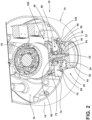
- a weighted member 100 is spaced-apart from the knob 30 and operably coupled thereto via a shaft assembly 50. As such, the weighted member 100 is configured for rotation with the shaft assembly 50 and the knob 30. As shown in FIG. 2 , the weighted member 100 is positioned within the interior cavity 16 of the base unit 14, while the head portion 32 of the knob 30 is externally accessible relative to the base unit 14. The weighted member 100 provides a sensory experience for a user when the user engages the knob 30 for rotation. Specifically, the weighted member 100 provides an increased moment of inertia or rotational inertia to the rotation of the knob 30 as operably coupled thereto.
- rotational inertia is meant to indicate the torque needed for a desired angular acceleration about a rotational axis.
- the knob 30 is contemplated to be comprised of a plastic material that may match the sidewall 15 of the base unit 14, which is also contemplated to be a plastic part.
- the weighted member 100 is contemplated to be comprised of a metal material to provide a substantial added mass to the shaft assembly 50, thereby increasing the rotational inertia of the knob 30 and the shaft assembly 50.
- the addition of the weighted member 100 provides a sensory experience to the user that simulates the engagement of a knob that is comprised of metal, or that has the mass of the weighted member 100.
- the weighted member 100 is positioned within the interior cavity 16 of the base unit 14, such that the weighted member 100 is concealed within the interior cavity 16 of the base unit 14.
- the weighted member 100 may be comprised of a less expensive metal material than a metal material that would be traditionally used for externally accessible knob.
- the present concept places mass internal to the base unit 14 of the blender 10 by way of the weighted member 100, which provides a greater opportunity to add mass with geometry optimized for an appropriate moment of inertia to enhance the user experience.
- the present solution also allows for the knob 30 to be made of materials that are more cost effective than metals, at the same time yielding superior sensorial qualities.
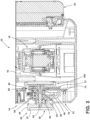
- the shaft assembly 50 includes a shaft member 52 having first and second ends 54, 56, wherein the second end 56 is positioned within the interior cavity 16 of the base unit 14 and the first end 54 is externally accessible relative to the base unit 14.
- the first end 54 of the shaft member 52 defines a first portion 53 of the shaft assembly 50.
- the first end 54 of the shaft member 52 is received within the interior channel 42 of the stem portion 34 of the knob 30 in assembly, such that the shaft member 52 is rigidly coupled to the knob 30 for rotation therewith.
- the shaft assembly 50 also includes a switch assembly 60.
- the switch assembly 60 is coupled to the second end 56 of the shaft member 52 in a rigid manner for rotation therewith.
- the switch assembly 60 provides a speed selection for the motor 18 and further provides tactile feedback to the user as a speed selection is made by rotating the knob 30.
- the shaft assembly 50 also includes a mounting bracket 80.
- the mounting bracket 80 interconnects the switch assembly 60 with the weighted member 100.
- the mounting bracket 80 is rigidly coupled to the switch assembly 60 and the weighted member 100, such that rotation of the knob 30 provides for rotation of the shaft member 52, the switch assembly 60, the mounting bracket 80 and the weighted member 100.
- the shaft assembly 50 is positioned through a number of component parts that do not rotate with the shaft assembly 50. These component parts include a front support bracket 70, a rear support bracket 72 a printed circuit board (PCB) 74.
- PCB printed circuit board
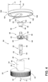
- the switch assembly 60 includes a body portion 62 having an interior channel 64 in which the second end 56 of the shaft member 52 is received to fixedly couple the switch assembly 60 to the shaft number 52.
- the switch assembly 60 further includes a stem portion 66 that inwardly extends from the body portion 62.
- the switch assembly 60 further includes an engagement member 68 that radially extends from the body portion 62.
- the engagement member 68 of the switch assembly 60 further includes an outwardly extending flange 69.
- the engagement member 68 of the switch assembly 60 is configured to engage a spring for biasing rotational movement of the knob 30, as further described below.
- the mounting bracket 80 includes a head portion 82 and a stem portion 84 that outwardly extends from the head portion 82.
- the head portion 82 of the mounting bracket 80 includes mounting bosses 83 which inwardly extend from the head portion 82 and are configured to be received within mounting apertures 104 centrally disposed on the weighted member 100.
- the head portion 82 of the mounting bracket 80 defines a second portion 55 of the shaft assembly 50.
- the stem portion 84 of the mounting bracket 80 includes an interior channel 86 in which the stem portion 66 of the switch assembly 60 is received to fixedly couple the switch assembly 60 to the mounting bracket 80.
- the weighted member 100 is shown having a substantially planar body portion 102.
- the body portion 102 includes the mounting apertures 104 that are centrally disposed thereon.
- the mounting apertures 104 are configured to receive the mounting bosses 83 of the mounting bracket 80 to fixedly couple the weighted member 100 to the mounting bracket 80, for rotation therewith.
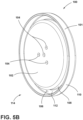
- the body portion 102 is surrounded by a channel 106, as best shown in FIG. 5B , wherein the channel 106 includes a first sidewall 108 spaced-apart from a second sidewall 110 and interconnected by an intermediate wall 112. In this way, the channel 106 defines an outwardly opening channel on the weighted member 100.
- the channel 106 defines a nonplanar portion of the weighted member 100, providing added mass at an outer perimeter 114 of the weighted member 100. Having the added mass positioned at the outer perimeter 114 of the weighted member 100 increases the moment of inertia or rotational inertia of the weighted member 100, as this added mass of the weighted member 100 is positioned furthest away from the axis of rotation A1 shown in FIGS. 4 and 6 .
- the weighted member 100 further includes an outer diameter 101 which is generally defined by the second sidewall 110 of the channel 106.
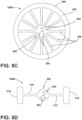
- FIG. 5C another configuration of a weighted member 100A is shown having a central body portion 300 with mounting apertures 304 disposed therethrough for coupling the weighted member 100A to the mounting bracket 80, for rotation therewith.
- the weighted member 100A further includes a number of spoke members 306 outwardly extending from the central body portion 300 and interconnecting the central body portion 300 with an outer ring 302.
- the outer ring 302 includes an outer diameter 308.
- FIG. 5D another configuration of a weighted member 100B is shown having a central body portion 300 with mounting apertures 304 disposed therethrough for coupling the weighted member 100B to the mounting bracket 80, for rotation therewith.
- the weighted member 100B further includes first and second arms 310, 312 outwardly extending from the central body portion 300.
- the first and second arms 310, 312 each include a weight 314, 316, respectively, that are interconnected to the central body portion 300 by the first and second arms 310, 312 and extended outwardly from the central body portion 300.
- the weighted members 100A, 100B do not need to be disk-shaped weighted members, like weighted member 100 described above, but may include other configurations, so long as the weighted members are balanced and symmetrical.
- the shaft assembly 50 is shown in an assembled condition and interconnecting the knob 30 and the weighted member 100.
- the rotational axis A1 is defined by the shaft assembly 50, such that the rotational inertia ( l ) (provided specifically by the weighted member 100) is equal to the mass ( m ) of the weighted member 100 times the square of the perpendicular distance ( r) to the axis of rotation A1.
- the shaft assembly 50 interconnects the knob 30 with the weighted member 100 in a rigid manner, such that these parts rotate together when a user engages the knob 30.
- the knob 30 includes an outer diameter 44 defined by the head portion 32 of the knob 30.
- the weighted member 100 includes an outer diameter 101 which is generally defined by the second sidewall 110 of the channel 106 disposed around the outer perimeter 114 of the weighted member 100. As shown in FIGS. 4 and 6 , the outer diameter 44 of the knob 30 is less than the outer diameter 101 of the weighted member 100. Said differently, the outer diameter 101 of the weighted member 100 is greater than the outer diameter 44 of the knob 30. With reference to FIGS. 4 and 6 , the outer diameter 101 of the weighted member 100 is twice the radius thereof as indicated at reference numeral r1 . As further shown in FIGS. 4 and 6 , the outer diameter 44 of the knob 30 is twice the radius thereof as indicated at reference numeral r2.
- the weighted member 100 provides a rotational inertia, realized by a user at the knob 30, that is consistent with the mass ( m ) of the weighted member 100, and the radius ( r1 ) of the weighted member 100, both of which are features of the weighted member 100 that are greater than the mass and the radius ( r2 ) of the knob 30.
- the present concept provides for a sensory experience for the user that includes a rotational inertia of the knob 30 (which is contemplated to be a plastic part) that is consistent with a heavier and larger knob.
- the present concept provides this sensory feature at the externally accessible knob 30 while the weighted member 100 is concealed within the base unit 14 of the blender 10.
- the shaft assembly 50 is shown with the weighted member 100 coupled thereto, and the front and rear support brackets 70, 72 and the PCB 74 positioned therearound.
- the front support bracket 70 includes a sidewall 120 and a top wall 122. Together, the sidewall 120 and the top wall 122 cooperate to partially define an interior cavity 124 for the front support bracket 70.
- a spring member 126 is housed within the interior cavity 124 of the front support bracket 70, as partially shown in FIG. 2 .
- the spring member 126 is shown in phantom in FIG. 7 . With reference to FIG. 8 , the spring member 126 is revealed with the front support bracket 70 removed.
- the spring member 126 includes a first arm 128 and a second arm 130 with a coiled portion 132 disposed therebetween.
- the switch assembly 60 is coupled to the shaft member 52 and is housed within the interior cavity 124 of the front support bracket 70, as partially shown in FIG. 2 .
- the first arm 128 of the spring member 126 engages the engagement member 68 of the switch assembly 60 at the flange 69 thereof.
- the second arm 130 of the spring member 126 engages the sidewall 120 of the front support bracket 70.
- Rotation of the shaft assembly 50 in the rotational direction as indicated by arrow R2 is contemplated to be provided by a user engaging the knob 30 and rotating the knob 30 towards the left. It is contemplated that rotation of the knob 30 in the rotational direction as indicated by arrow R2 provides a pulse setting which rotates the switch assembly 60 in the direction as indicated by arrow R3 to load the spring member 126. Once the force imparted on the knob 30 is removed, the spring member 126 resiliently rotates the switch assembly downward in the direction as indicated by arrow R4 to an off position shown in FIG. 8 . Thus, the spring member 126 biases the switch assembly 60 to an off or at-rest position when the switch assembly 60 is rotated to a pulse setting which selectively powers the motor 18 in an intermittent blending procedure controlled by the user.
- the switch assembly 60 includes an upper surface 133 having a plurality of recesses 134 and ridges 135 disposed thereon.
- a detent feature 136 includes a detent member 138 in the form of a ball that is biased in a vertically downward direction by a spring member 140.
- the detent feature 136 is housed within the interior cavity 124 ( FIG. 7 ) of the front support bracket 70 and is positioned such that the spring member 140 thereof acts against the top wall 122 ( FIG. 7 ) of the front support bracket 70.
- the switch assembly 60 will rotate in the direction as indicated by arrow R4 and the detent member 138 will climb over the ridges 135 to load the spring member 140 and be received in adjacent recesses 134 along the upper surface 133 of the switch assembly 60, to which the detent member 138 is biased.
- the speed selection may be provided in an ascending speed level or a descending speed level as the switch assembly 60 rotates in the direction as indicated by arrow R4.
- Rotation of the knob 30 to the right in the direction as indicated by arrow R1 and the switch assembly 60 in the direction as indicated by arrow R4 does not load the spring member 126, such that spring member 126 does not bias the switch assembly 60 back to the at-rest or off position shown in FIG. 8 when a speed selection is made by a user.
- a motor speed may be selected by a user, and the motor 18 may remain at the selected motor speed until the user returns the switch assembly 60 to a lower speed selection or the at-rest or off position by rotating the knob 30 in the direction as indicated by arrow R2 to decrease the speed or turn off the motor.
- the above-referenced blender 10 can include a controller in the form of a microprocessor, or the like, that can include programming to operate the blender 10, including based on user inputs received through the user interface 20 discussed above.
- the programming can include either firmware or software that is specifically adapted to operate the motor 18 via a current received from the battery 22.
- the programming can be adapted to maintain an acceptably low temperature of the battery 22 and/or the motor 18 in a proactive manner based on the current drawn by the motor 18.
- the knob 30 is provided to operate the motor 18 at different speeds (e.g., high, medium, and low). As can be appreciated, the operation of the motor 18 at these varying speeds will result in correspondingly varying current draws.
- low speed operation may result in a current draw of about 15 amps, with mid-speed operation having a current draw of 20 amps, and high speed operation drawing a current of 40 amps.
- operation of the motor 18 at the high speed setting will result in faster heating of the motor 18 and/or the battery 22, such that a timer can be implemented that only allows operation at a speed drawing 40 amps for a certain amount of time to prevent excessive heating.
- the controller programming can be such that, when the user fully rotates the knob 30 to the right, the motor 18 is operated at the full high speed for a predetermined interval (e.g., about 20 seconds, or in some examples about 10 seconds) before the speed is reduced (e.g., by between about 5% and 10% to reduce the heating effect of such operation, while still operating the motor 18 at a speed that may be perceived as acceptably high by the user.
- a predetermined interval e.g., about 20 seconds, or in some examples about 10 seconds
- the speed is reduced (e.g., by between about 5% and 10% to reduce the heating effect of such operation, while still operating the motor 18 at a speed that may be perceived as acceptably high by the user.
- the lower speed operations may allow for longer intervals (e.g., at least about 40 seconds) before a similar reduction in speed is implemented.
- the software can also implement a cool-down time interval requirement, such that the overall timer is maintained during rapid pulses when the knob 30 is intermittently turned to the left.
- the lid assembly 26 is shown exploded away from the open top 28 of the jar assembly 12 to thereby provide access to the inner cavity 24 of the jar assembly 12.
- the lid assembly 26 includes a body portion 150 having a head portion 151 with a centrally disposed aperture 152.
- a cap member 154 is removably received on the centrally disposed aperture 152 of the lid assembly 26.
- the lid assembly 26 further includes a handle 156 which extends outwardly from the head portion 151 and is contemplated to be engaged by a user to remove the lid assembly 26 from the open top 28 of the jar assembly 12.
- the lid assembly 26 further includes a stem portion 160 extending downwardly from the head portion 151.
- the stem portion 160 includes a seal member 170 disposed thereon.
- the seal member 170 is contemplated to be a removable seal member with respect to the lid assembly 26. In use, the seal member 170 is configured to seal against an interior surface 25 of the inner cavity 24 of the jar assembly 12 to keep food items within the jar assembly 12 during a blending procedure.
- the cap member 154 includes a head portion 212 having recesses 214, 216 disposed thereon which are contemplated to be engaged by a user to twist the cap member 154 into engagement with the body portion 150 of the lid assembly 26.
- the cap member 154 includes a number of interlock features 155A that cooperate with reciprocal interlock features 155B disposed within the body portion 150 of the lid assembly 26 at the centrally disposed aperture 152 to releasably retain the cap member 154 in place in a twist-lock configuration, as further described below.
- a cup portion 218 extends outwardly from the head portion 212 of the cap member 154 and may be used as a measuring cup, as further described below.
- the centrally disposed aperture 152 of the body portion 150 of the lid assembly 26 provides access to the inner cavity 24 of the jar assembly 12 when the cap member 154 is removed therefrom.
- the stem portion 160 of the lid assembly 26 includes a receiving channel 162 that is circumferentially disposed around an entirety of the stem portion 160. As such, the receiving channel 162 defines a recess provided around the stem portion 160.
- the receiving channel 162 is an outwardly opening receiving channel that may include a generally C-shaped structure having an upper edge 164, a lower edge 166 and an intermediate portion 168 interconnecting the upper edge 164 and the lower edge 166.
- the receiving channel 162 further includes a plurality of locating recesses 169 that upwardly extend from the upper edge 164 thereof.
- the seal member 170 includes a body portion 172 having an upper edge 174 and a lower edge 176.
- Upper and lower sweep members 178, 180 outwardly extend from the body portion 172 of the seal member 170.
- the upper and lower sweep members 178, 180 are configured to engage the interior surface 25 of the inner cavity 24 as received within inner cavity 24 of the jar assembly 12. This configuration is shown in FIG.
- the lid assembly 26 and the jar assembly 12 may be comprised of a clear or transparent polymeric material, as shown in FIGS. 10 , 11 and 13 .
- the seal member 170 may be comprised of a silicone material, such that the upper and lower sweep members 178, 180 are contemplated to be flexibly resilient members. As a removable member, the seal member 170 can be removed from the stem portion 160 of the lid assembly 26, such that the seal member 170 can be washed, and so can the receiving channel 162 of the lid assembly 26. Being a flexibly resilient member, the seal member 170 can be stretched to move into the receiving channel 162 over the lower edge 166 of the receiving channel 162. As shown in FIG.
- the seal member 170 includes a plurality of locating features 182 that upwardly extend from the upper edge 174 of the body portion 172 of the seal member 170.
- the upwardly extending locating features 182 are received in the reciprocal locating recesses 169 of the receiving channel 162 as the seal member 170 is positioned therein.
- the seal member includes four upwardly extending locating features 182 that are contemplated to be received in four locating recesses 169 of the receiving channel 162 disposed at corner portions of the receiving channel 162.
- more or fewer locating features may be provided on the seal member 170.
- the centrally disposed aperture 152 has the cap member 154 removed therefrom to reveal a rim portion 190.
- the rim portion 190 includes upper and lower surfaces 192, 194. Further, the rim portion 190 includes a first portion 190A and a second portion 190B with access slots 196, 198 positioned therebetween.
- the first and second portions 190A, 190B are identical to one another, such that the description of the first portion 190A provided herein will also describe the second portion 190B.
- the first portion 190A of the rim portion 190 includes a first engagement member 200 spaced-apart from a second engagement member 202 which is further spaced-apart from a third engagement member 204.
- the second and third engagement members 202 and 204 are substantially similar to one another and outwardly extend from the lower surface 194 of the rim portion 190.
- the first engagement member 200 also outwardly extends from the lower surface 194 of the rim portion 190 and includes an angled leading portion 206 that acts as an introductory ramp portion for one of the interlock features 155A of the cap member 154.
- a cradle portion 208 Positioned between the first engagement member 200 and the second engagement member 202 is a cradle portion 208, wherein an interlock feature 155A of the cap member 154 is received when the cap member 154 is in a locked position on the body portion 150 of the lid assembly 26, as shown in FIG. 15 .
- the cap member 154 is coupled to the body portion 150 of the lid assembly 26
- the cap member 154 is vertically received at the centrally disposed aperture 152 of the body portion 150 of the lid assembly 26 in the direction as indicated by arrow 210.
- the interlock feature 155A of the cap member 154 will be received through the access slot 196 to then engage the lower surface 194 of the rim portion 190.
- the interlock feature 155A of the cap member 154 will rotate in the direction as indicated by arrow R5 until it reaches the angled leading portion 206 of the first engagement member 200. As a user continues the rotation of the cap member 154, the interlock feature 155A will pass over the first engagement member 200 and stop rotational movement at the second engagement member 202. When rotation of the interlock feature 155A is stopped by the second engagement member 202, the interlock features 155A is received in the cradle portion 208 of the rim portion 190, as shown in FIG. 15 .
- the cup portion 218 of the cap member 154 includes a sidewall 220 extending outwardly from a lower surface 212B of the head portion 212.
- the sidewall 220 surrounds a receiving well 222 which can be used by a user to measure ingredients when the cap member 154 is removed from the body portion 150 of the lid assembly 26.
- the cup portion 218 may further include ingredient measuring indicia 224 positioned on and visible on an outer surface 226 of the sidewall 220 for use in measuring ingredients received in the receiving well 222.
- the ingredient measuring indicia 224 may also be positioned on an inner surface of the sidewall 220.
- the term "ingredient measuring indicia” describes visible markings on the cup portion 218 that indicate a volume of ingredients received within the receiving well 222. Such markings may include cup, tablespoon, teaspoon or any other volume metric suitable for measuring ingredients to be used in the blender 10.
- the interlock feature 155A of the cap member 154 is shown outwardly extending from the outer surface 226 of the sidewall 220 of the cup portion 218.
- FIG. 15 the interlock feature 155A of the cap member 154 is shown outwardly extending from the outer surface 226 of the sidewall 220 of the cup portion 218.
- the interlock feature 155A is shown as being received within the cradle portion 208 of the rim portion 190 of the body portion 150 of the lid assembly 26, such that the cap member 154 is shown in a locked position in FIG. 15 .
- Rotating the cap member 154 such that the interlock features 155A thereof align with the access slots 196, 198 will rotate the cap member 154 to an unlocked position, wherein the cap member 154 can be released from the body portion 150 of the lid assembly 26.
- the cap member 154 is operable between locked and unlocked positions relative to the body portion 150 of the lid assembly 26 due to the reciprocal interlock features 155A and 155B provided therebetween.
- an appliance includes a base unit having a sidewall surrounding an interior cavity.
- a shaft assembly includes a first portion extending outwardly from the sidewall of the base unit.
- the shaft assembly further includes a second portion positioned within the interior cavity.
- a weighted member is operably coupled to the second portion of the shaft assembly for rotation therewith.
- a knob is positioned on the first portion of the shaft assembly for rotation therewith. The weighted member increases the rotational inertia of the knob assembly as operably coupled thereto through the shaft assembly.
- an appliance includes a base unit having a sidewall surrounding an interior cavity.
- a shaft assembly is disposed through the sidewall of the base unit and includes first and second portions.
- a knob is operably coupled to the first portion of the shaft assembly and is externally accessible relative to the base unit.
- a weighted member is operably coupled to the second portion of the shaft assembly for rotation therewith. The weighted member is positioned within the interior cavity of the base unit.
- an appliance includes a base unit having a sidewall surrounding an interior cavity.
- a shaft member includes first and second ends. The second end is positioned within the interior cavity of the base unit and the first end is externally accessible relative to the base unit.
- a knob is positioned on the first end of the shaft member. The knob includes a head portion and a stem portion extending inwardly from the head portion. A distal end of the stem portion is positioned within the interior cavity of the base unit.
- a weighted member is operably coupled to the second end of the shaft member for rotation therewith within the interior cavity of the base unit.
- an appliance includes a base unit with a sidewall surrounding an interior cavity.
- a shaft assembly includes a first portion extending outwardly from the sidewall of the base unit and a second portion positioned within the interior cavity.
- a weighted member is operably coupled to the second portion of the shaft assembly for rotation therewith.
- a knob is positioned on the first portion of the shaft assembly for rotation therewith.
- the knob includes a head portion and a stem portion.
- the stem portion inwardly extends from the head portion.
- the head portion of the knob is externally accessible relative to the base unit.
- the stem portion includes a distal end that is positioned within the interior cavity.
- the shaft assembly includes a shaft member having first and second ends.
- the first end of the shaft member is received in an interior channel disposed along the stem portion of the knob.
- a switch assembly is coupled to the second end of the shaft member for rotation therewith.
- the weighted member includes a generally planar body portion.
- the weighted member includes an outwardly opening channel defining an added mass disposed along an outer perimeter of the weighted member.
- the outwardly opening channel includes first and second sidewalls that are spaced-apart from one another and interconnected by an intermediate wall.
- the weighted member includes a mass that is greater than a mass of the knob.
- the weighted member includes an outer diameter that is greater than an outer diameter of the knob.
- an appliance includes a base unit with a sidewall surrounding an interior cavity.
- a shaft assembly is disposed through the sidewall of the base unit and includes first and second portions.
- a knob is operably coupled to the first portion of the shaft assembly and is externally accessible relative to the base unit.
- a weighted member is operably coupled to the second portion of the shaft assembly for rotation therewith. The weighted member is positioned within the interior cavity of the base unit.
- the weighted member includes an outer diameter that is greater than an outer diameter of the knob.
- the knob is comprised of a plastic material.
- the weighted member is comprised of a metal material.
- an appliance includes a base unit with a sidewall surrounding an interior cavity.
- a shaft member includes a first end and a second end. The second end is positioned within the interior cavity of the base unit and the first end is externally accessible relative to the base unit.
- a knob is positioned on the first end of the shaft member.
- a weighted member is operably coupled to the second end of the shaft member for rotation therewith within the interior cavity of the base unit.
- the knob includes a head portion and a stem portion extending inwardly from the head portion.
- the stem portion includes a distal end that is positioned within the interior cavity of the base unit.
- the weighted member includes an added mass disposed along an outer perimeter of the weighted member.
- the weighted member includes an outer diameter that is greater than an outer diameter of the knob.
- an appliance includes a base unit having a sidewall surrounding an interior cavity.
- a shaft assembly includes a first portion extending outwardly from the sidewall of the base unit and a second portion positioned within the interior cavity.
- a weighted member is operably coupled to the second portion of the shaft assembly for rotation therewith.
- a knob is positioned on the first portion of the shaft assembly for rotation therewith.
- the knob includes a head portion and a stem portion.
- the stem portion inwardly extends from the head portion.
- the head portion of the knob is externally accessible relative to the base unit.
- the stem portion includes a distal end that is positioned within the interior cavity.
- the shaft assembly includes a shaft member having first and second ends.
- the first end of the shaft member is received in an interior channel disposed along the stem portion of the knob.
- a switch assembly is coupled to the second end of the shaft member for rotation therewith.
- the switch assembly is further coupled to a spring member to bias movement of the switch assembly.
- the weighted member includes a generally planar body portion.
- the weighted member includes an outwardly opening channel defining an added mass disposed along an outer perimeter of the weighted member.
- the outwardly opening channel includes first and second sidewalls that are spaced-apart from one another and interconnected by an intermediate wall.
- the generally planar body portion of the weighted member includes one or more mounting apertures disposed therethrough.
- the weighted member includes a mass that is greater than a mass of the knob.
- the weighted member includes an outer diameter that is greater than an outer diameter of the knob.
- the weighted member is comprised of a metal material.
- the knob is comprised of a plastic material.
Landscapes
- Engineering & Computer Science (AREA)
- Physics & Mathematics (AREA)
- General Physics & Mathematics (AREA)
- Automation & Control Theory (AREA)
- Mechanical Engineering (AREA)
- Food Science & Technology (AREA)
- Rotary Switch, Piano Key Switch, And Lever Switch (AREA)
Abstract
Description
- The present disclosure generally relates to a user interface for an appliance, and more specifically, to a user interface having a rotatable knob coupled to a weighted member configured to increase rotational inertia realized by a user when rotating the knob.
- According to one aspect of the present disclosure, an appliance includes a base unit having a sidewall surrounding an interior cavity. A shaft assembly includes a first portion extending outwardly from the sidewall of the base unit. The shaft assembly further includes a second portion positioned within the interior cavity. A weighted member is operably coupled to the second portion of the shaft assembly for rotation therewith. A knob is positioned on the first portion of the shaft assembly for rotation therewith. The weighted member increases the rotational inertia of the knob assembly as operably coupled thereto through the shaft assembly.
- According to another aspect of the present disclosure, an appliance includes a base unit having a sidewall surrounding an interior cavity. A shaft assembly is disposed through the sidewall of the base unit and includes first and second portions. A knob is operably coupled to the first portion of the shaft assembly and is externally accessible relative to the base unit. A weighted member is operably coupled to the second portion of the shaft assembly for rotation therewith. The weighted member is positioned within the interior cavity of the base unit.
- According to yet another aspect of the present disclosure, an appliance includes a base unit having a sidewall surrounding an interior cavity. A shaft member includes first and second ends. The second end is positioned within the interior cavity of the base unit and the first end is externally accessible relative to the base unit. A knob is positioned on the first end of the shaft member. The knob includes a head portion and a stem portion extending inwardly from the head portion. A distal end of the stem portion is positioned within the interior cavity of the base unit. A weighted member is operably coupled to the second end of the shaft member for rotation therewith within the interior cavity of the base unit.
- According to one aspect of the present disclosure, an appliance includes a base unit with a sidewall surrounding an interior cavity. A shaft assembly includes a first portion extending outwardly from the sidewall of the base unit and a second portion positioned within the interior cavity. A weighted member is operably coupled to the second portion of the shaft assembly for rotation therewith. A knob is positioned on the first portion of the shaft assembly for rotation therewith.
- According to another aspect of the present disclosure, an appliance includes a base unit with a sidewall surrounding an interior cavity. A shaft assembly is disposed through the sidewall of the base unit and includes first and second portions. A knob is operably coupled to the first portion of the shaft assembly and is externally accessible relative to the base unit. A weighted member is operably coupled to the second portion of the shaft assembly for rotation therewith. The weighted member is positioned within the interior cavity of the base unit.
- According to yet another aspect of the present disclosure, an appliance includes a base unit with a sidewall surrounding an interior cavity. A shaft member includes a first end and a second end. The second end is positioned within the interior cavity of the base unit and the first end is externally accessible relative to the base unit. A knob is positioned on the first end of the shaft member. A weighted member is operably coupled to the second end of the shaft member for rotation therewith within the interior cavity of the base unit.
- These and other features, advantages, and objects of the present disclosure will be further understood and appreciated by those skilled in the art by reference to the following specification, claims, and appended drawings.
- In the drawings:
-
FIG. 1A is a top perspective view of an appliance having a base unit, a jar assembly and a lid assembly; -
FIG. 1B is a top perspective view of the appliance ofFIG. 1A ; -
FIG. 2 is a cross-sectional view of the appliance ofFIG. 1A taken at line II; -
FIG. 3 is a cross-sectional view of the appliance ofFIG. 1B taken at line III; -
FIG. 4 is an exploded perspective view of a shaft assembly, a knob and a weighted member; -
FIG. 5A is a rear perspective view of the weighted member ofFIG. 4 ; -
FIG. 5B is a front perspective view of the weighted member ofFIG. 5A ; -
FIG. 5C is a front are elevational view of a weighted member; -
FIG. 5D is a front are elevational view of a weighted member; -
FIG. 6 is an assembled perspective view of the shaft assembly, knob and weighted member ofFIG. 4 ; -
FIG. 7 is a top perspective view of motor control components for the appliance ofFIG. 1A ; -
FIG. 8 is a top perspective view of the motor control components ofFIG. 7 with a front support bracket removed therefrom; -
FIG. 9 is a top perspective view of the motor control components ofFIG. 8 ; -
FIG. 10 is a top perspective view of the appliance ofFIG. 1A with a lid assembly exploded away from the jar assembly; -
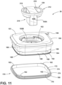
FIG. 11 is an exploded top perspective view of the lid assembly ofFIG. 10 ; -
FIG. 12 is a top perspective view of the appliance ofFIG. 10 with a seal member is shown disposed within the jar assembly; -
FIG. 13 is a top perspective view of a lid assembly; -
FIG. 14 is a fragmentary bottom perspective view of the lid assembly ofFIG. 13 with a cap member removed therefrom; and -
FIG. 15 is a fragmentary bottom perspective view of the lid assembly ofFIG. 13 . - The components in the figures are not necessarily to scale, emphasis instead being placed upon illustrating the principles described herein.
- The present illustrated embodiments reside primarily in combinations of method steps and apparatus components related to an appliance, and a user interface thereof. Accordingly, the apparatus components and method steps have been represented, where appropriate, by conventional symbols in the drawings, showing only those specific details that are pertinent to understanding the embodiments of the present disclosure so as not to obscure the disclosure with details that will be readily apparent to those of ordinary skill in the art having the benefit of the description herein. Further, like numerals in the description and drawings represent like elements.
- For purposes of description herein, the terms "upper," "lower," "right," "left," "rear," "front," "vertical," "horizontal," and derivatives thereof shall relate to the disclosure as oriented in
FIG. 1A . Unless stated otherwise, the term "front" shall refer to the surface of the element closer to an intended viewer, and the term "rear" shall refer to the surface of the element further from the intended viewer. However, it is to be understood that the disclosure may assume various alternative orientations, except where expressly specified to the contrary. It is also to be understood that the specific devices and processes illustrated in the attached drawings, and described in the following specification are simply exemplary embodiments of the inventive concepts defined in the appended claims. Hence, specific dimensions and other physical characteristics relating to the embodiments disclosed herein are not to be considered as limiting, unless the claims expressly state otherwise. - The terms "including," "comprises," "comprising," or any other variation thereof, are intended to cover a non-exclusive inclusion, such that a process, method, article, or apparatus that comprises a list of elements does not include only those elements but may include other elements not expressly listed or inherent to such process, method, article, or apparatus. An element preceded by "comprises a ... " does not, without more constraints, preclude the existence of additional identical elements in the process, method, article, or apparatus that comprises the element.
- Referring now to
FIG. 1A ,reference numeral 10 generally designates a small appliance in the form of a blender. Theblender 10, as shown inFIG. 1A , includes ajar assembly 12 that is selectively supported on abase unit 14. Thejar assembly 12 includes aninner cavity 24 and alid assembly 26 disposed on an open top 28 (FIG. 10 ) thereof. Thebase unit 14 includes asidewall 15 surrounding aninterior cavity 16. A motor 18 (FIGS. 2 and3 ) is housed within theinterior cavity 16 of thebase unit 14. In use, themotor 18 is configured to drive a blade assembly disposed within theinner cavity 24 of thejar assembly 12. As further shown inFIG. 1A , theblender 10 includes auser interface 20 which includes aknob 30 that is contemplated to be electronically coupled to themotor 18, and configured to adjust various settings of themotor 18, as further described below. Theuser interface 20 further includes a number offunction buttons 31 and apower level display 33. Thefunction buttons 31 are contemplated to provide functional settings for theblender 10, such as blade rotational direction and other like functions. Theknob 30 of theuser interface 20 is contemplated to be rotatably coupled to thebase unit 14. Theknob 30 includes ahead portion 32 that includes anouter diameter 44. - Referring now to
FIG. 1B , theblender 10 is contemplated to be a cordless appliance that is powered using a rechargeable power source in the form of aremovable battery 22. Thebattery 22 is disclosed in an application titled CHARGER AND BATTERY FOR CORDLESS APPLIANCE that was filed in with the United States Patent and Trademark Office on March 1, 2022 with the Atty Docket No. SUB-15280F-US-PSP, the entirety of which is incorporated herein by reference. Thepower level display 33 of theuser interface 20 is contemplated to provide a visual indicator of the remaining power left in thebattery 22. - Referring now to
FIG. 2 , theknob 30 of theuser interface 20 is contemplated to be rotatably coupled to thebase unit 14. Theknob 30 includes ahead portion 32 and astem portion 34 extending inwardly from thehead portion 32. Thehead portion 32 of theknob 30 is positioned outside of theinterior cavity 16 of thebase unit 14 and is externally accessible relative to thebase unit 14. Thehead portion 32 of theknob 30 is contemplated to be engaged by a user for selecting a motor speed or other like function of theblender 10. Thestem portion 34 includes first andsecond portions distal end 40. Thesecond portion 38 and thedistal end 40 of thestem portion 34 are positioned within theinterior cavity 16 of thebase unit 14. Thefirst portion 36 is positioned outside of theinterior cavity 16 of thebase unit 14 and is externally accessible relative to thebase unit 14. Thestem portion 34 further includes aninterior channel 42 which defines a hollow portion of theknob 30. As used herein, the term "externally accessible" is meant to describe a component part of theblender 10 that is positioned on an exterior of theblender 10. Specifically, the term "externally accessible" describes component parts that can be engaged by a user on the outside portion of thebase unit 14, as opposed to component parts of theblender 10 that are disposed within theinterior cavity 16 of thebase unit 14. - As further shown in
FIG. 2 , aweighted member 100 is spaced-apart from theknob 30 and operably coupled thereto via ashaft assembly 50. As such, theweighted member 100 is configured for rotation with theshaft assembly 50 and theknob 30. As shown inFIG. 2 , theweighted member 100 is positioned within theinterior cavity 16 of thebase unit 14, while thehead portion 32 of theknob 30 is externally accessible relative to thebase unit 14. Theweighted member 100 provides a sensory experience for a user when the user engages theknob 30 for rotation. Specifically, theweighted member 100 provides an increased moment of inertia or rotational inertia to the rotation of theknob 30 as operably coupled thereto. As used herein, the term "rotational inertia" is meant to indicate the torque needed for a desired angular acceleration about a rotational axis. In the present concept, the rotational axis A1 (FIG. 4 ) is defined by theshaft assembly 50, such that the rotational inertia (l) (provided specifically by the weighted member 100) is equal to the mass (m) times the square of the perpendicular distance (r) to the axis of rotation A1, which can be expressed as l = mr2. - In the present concept, the
knob 30 is contemplated to be comprised of a plastic material that may match thesidewall 15 of thebase unit 14, which is also contemplated to be a plastic part. Theweighted member 100 is contemplated to be comprised of a metal material to provide a substantial added mass to theshaft assembly 50, thereby increasing the rotational inertia of theknob 30 and theshaft assembly 50. The addition of theweighted member 100 provides a sensory experience to the user that simulates the engagement of a knob that is comprised of metal, or that has the mass of theweighted member 100. As described above, theweighted member 100 is positioned within theinterior cavity 16 of thebase unit 14, such that theweighted member 100 is concealed within theinterior cavity 16 of thebase unit 14. In this way, theweighted member 100 may be comprised of a less expensive metal material than a metal material that would be traditionally used for externally accessible knob. Thus, the present concept places mass internal to thebase unit 14 of theblender 10 by way of theweighted member 100, which provides a greater opportunity to add mass with geometry optimized for an appropriate moment of inertia to enhance the user experience. The present solution also allows for theknob 30 to be made of materials that are more cost effective than metals, at the same time yielding superior sensorial qualities. - Referring now to
FIGS. 2 and3 , theshaft assembly 50 includes ashaft member 52 having first and second ends 54, 56, wherein thesecond end 56 is positioned within theinterior cavity 16 of thebase unit 14 and thefirst end 54 is externally accessible relative to thebase unit 14. Thefirst end 54 of theshaft member 52 defines afirst portion 53 of theshaft assembly 50. Thefirst end 54 of theshaft member 52 is received within theinterior channel 42 of thestem portion 34 of theknob 30 in assembly, such that theshaft member 52 is rigidly coupled to theknob 30 for rotation therewith. As further shown inFIGS. 2 and3 , theshaft assembly 50 also includes aswitch assembly 60. Theswitch assembly 60 is coupled to thesecond end 56 of theshaft member 52 in a rigid manner for rotation therewith. In use, theswitch assembly 60 provides a speed selection for themotor 18 and further provides tactile feedback to the user as a speed selection is made by rotating theknob 30. As further shown inFIGS. 2 and3 , theshaft assembly 50 also includes a mountingbracket 80. In assembly, the mountingbracket 80 interconnects theswitch assembly 60 with theweighted member 100. The mountingbracket 80 is rigidly coupled to theswitch assembly 60 and theweighted member 100, such that rotation of theknob 30 provides for rotation of theshaft member 52, theswitch assembly 60, the mountingbracket 80 and theweighted member 100. As further shown inFIGS. 2 and3 , theshaft assembly 50 is positioned through a number of component parts that do not rotate with theshaft assembly 50. These component parts include afront support bracket 70, a rear support bracket 72 a printed circuit board (PCB) 74. - Referring now to
FIG. 4 , theswitch assembly 60 includes abody portion 62 having aninterior channel 64 in which thesecond end 56 of theshaft member 52 is received to fixedly couple theswitch assembly 60 to theshaft number 52. Theswitch assembly 60 further includes astem portion 66 that inwardly extends from thebody portion 62. Theswitch assembly 60 further includes anengagement member 68 that radially extends from thebody portion 62. Theengagement member 68 of theswitch assembly 60 further includes an outwardly extendingflange 69. Theengagement member 68 of theswitch assembly 60 is configured to engage a spring for biasing rotational movement of theknob 30, as further described below. - With further reference to
FIG. 4 , the mountingbracket 80 includes ahead portion 82 and astem portion 84 that outwardly extends from thehead portion 82. Thehead portion 82 of the mountingbracket 80 includes mountingbosses 83 which inwardly extend from thehead portion 82 and are configured to be received within mountingapertures 104 centrally disposed on theweighted member 100. Thehead portion 82 of the mountingbracket 80 defines asecond portion 55 of theshaft assembly 50. Thestem portion 84 of the mountingbracket 80 includes aninterior channel 86 in which thestem portion 66 of theswitch assembly 60 is received to fixedly couple theswitch assembly 60 to the mountingbracket 80. - Referring now to
FIGS. 5A and5B , theweighted member 100 is shown having a substantiallyplanar body portion 102. Thebody portion 102 includes the mountingapertures 104 that are centrally disposed thereon. In assembly, the mountingapertures 104 are configured to receive the mountingbosses 83 of the mountingbracket 80 to fixedly couple theweighted member 100 to the mountingbracket 80, for rotation therewith. Thebody portion 102 is surrounded by achannel 106, as best shown inFIG. 5B , wherein thechannel 106 includes afirst sidewall 108 spaced-apart from asecond sidewall 110 and interconnected by anintermediate wall 112. In this way, thechannel 106 defines an outwardly opening channel on theweighted member 100. As thebody portion 102 of theweighted member 100 is a generally planar portion, thechannel 106 defines a nonplanar portion of theweighted member 100, providing added mass at anouter perimeter 114 of theweighted member 100. Having the added mass positioned at theouter perimeter 114 of theweighted member 100 increases the moment of inertia or rotational inertia of theweighted member 100, as this added mass of theweighted member 100 is positioned furthest away from the axis of rotation A1 shown inFIGS. 4 and6 . Theweighted member 100 further includes anouter diameter 101 which is generally defined by thesecond sidewall 110 of thechannel 106. - Referring now to
FIG. 5C , another configuration of aweighted member 100A is shown having acentral body portion 300 with mountingapertures 304 disposed therethrough for coupling theweighted member 100A to the mountingbracket 80, for rotation therewith. Theweighted member 100A further includes a number ofspoke members 306 outwardly extending from thecentral body portion 300 and interconnecting thecentral body portion 300 with anouter ring 302. Theouter ring 302 includes anouter diameter 308. - Referring now to
FIG. 5D , another configuration of aweighted member 100B is shown having acentral body portion 300 with mountingapertures 304 disposed therethrough for coupling theweighted member 100B to the mountingbracket 80, for rotation therewith. Theweighted member 100B further includes first andsecond arms central body portion 300. The first andsecond arms weight central body portion 300 by the first andsecond arms central body portion 300. Thus, as shown inFIGS. 5C and 5D , theweighted members weighted member 100 described above, but may include other configurations, so long as the weighted members are balanced and symmetrical. - Referring now to
FIG. 6 , theshaft assembly 50 is shown in an assembled condition and interconnecting theknob 30 and theweighted member 100. The rotational axis A1 is defined by theshaft assembly 50, such that the rotational inertia (l) (provided specifically by the weighted member 100) is equal to the mass (m) of theweighted member 100 times the square of the perpendicular distance (r) to the axis of rotation A1. As shown inFIGS. 4 and6 , theshaft assembly 50 interconnects theknob 30 with theweighted member 100 in a rigid manner, such that these parts rotate together when a user engages theknob 30. As noted above, theknob 30 includes anouter diameter 44 defined by thehead portion 32 of theknob 30. As further noted above, theweighted member 100 includes anouter diameter 101 which is generally defined by thesecond sidewall 110 of thechannel 106 disposed around theouter perimeter 114 of theweighted member 100. As shown inFIGS. 4 and6 , theouter diameter 44 of theknob 30 is less than theouter diameter 101 of theweighted member 100. Said differently, theouter diameter 101 of theweighted member 100 is greater than theouter diameter 44 of theknob 30. With reference toFIGS. 4 and6 , theouter diameter 101 of theweighted member 100 is twice the radius thereof as indicated at reference numeral r1. As further shown inFIGS. 4 and6 , theouter diameter 44 of theknob 30 is twice the radius thereof as indicated at reference numeral r2. In this way, theweighted member 100 provides a rotational inertia, realized by a user at theknob 30, that is consistent with the mass (m) of theweighted member 100, and the radius (r1) of theweighted member 100, both of which are features of theweighted member 100 that are greater than the mass and the radius (r2) of theknob 30. Thus, the present concept provides for a sensory experience for the user that includes a rotational inertia of the knob 30 (which is contemplated to be a plastic part) that is consistent with a heavier and larger knob. Again, the present concept provides this sensory feature at the externallyaccessible knob 30 while theweighted member 100 is concealed within thebase unit 14 of theblender 10. - Referring now to
FIG. 7 , theshaft assembly 50 is shown with theweighted member 100 coupled thereto, and the front andrear support brackets PCB 74 positioned therearound. Thefront support bracket 70 includes asidewall 120 and atop wall 122. Together, thesidewall 120 and thetop wall 122 cooperate to partially define aninterior cavity 124 for thefront support bracket 70. Aspring member 126 is housed within theinterior cavity 124 of thefront support bracket 70, as partially shown inFIG. 2 . Thespring member 126 is shown in phantom inFIG. 7 . With reference toFIG. 8 , thespring member 126 is revealed with thefront support bracket 70 removed. Thespring member 126 includes afirst arm 128 and asecond arm 130 with acoiled portion 132 disposed therebetween. As shown inFIG. 8 , theswitch assembly 60 is coupled to theshaft member 52 and is housed within theinterior cavity 124 of thefront support bracket 70, as partially shown inFIG. 2 . Thefirst arm 128 of thespring member 126 engages theengagement member 68 of theswitch assembly 60 at theflange 69 thereof. Thesecond arm 130 of thespring member 126 engages thesidewall 120 of thefront support bracket 70. Thus, rotating theshaft assembly 50 in the rotational direction as indicated by arrow R2 raises theengagement member 68 in the direction as indicated by arrow R3, such that a force is applied to thespring 126. Rotation of theshaft assembly 50 in the rotational direction as indicated by arrow R2 is contemplated to be provided by a user engaging theknob 30 and rotating theknob 30 towards the left. It is contemplated that rotation of theknob 30 in the rotational direction as indicated by arrow R2 provides a pulse setting which rotates theswitch assembly 60 in the direction as indicated by arrow R3 to load thespring member 126. Once the force imparted on theknob 30 is removed, thespring member 126 resiliently rotates the switch assembly downward in the direction as indicated by arrow R4 to an off position shown inFIG. 8 . Thus, thespring member 126 biases theswitch assembly 60 to an off or at-rest position when theswitch assembly 60 is rotated to a pulse setting which selectively powers themotor 18 in an intermittent blending procedure controlled by the user. - Referring now to
FIG. 9 , theswitch assembly 60 includes anupper surface 133 having a plurality ofrecesses 134 andridges 135 disposed thereon. Adetent feature 136 includes adetent member 138 in the form of a ball that is biased in a vertically downward direction by aspring member 140. Thedetent feature 136 is housed within the interior cavity 124 (FIG. 7 ) of thefront support bracket 70 and is positioned such that thespring member 140 thereof acts against the top wall 122 (FIG. 7 ) of thefront support bracket 70. Thus, when a user engages theknob 30 to rotate theknob 30 to the right in the rotational direction as indicated by arrow R1, theswitch assembly 60 will rotate in the direction as indicated by arrow R4 and thedetent member 138 will climb over theridges 135 to load thespring member 140 and be received inadjacent recesses 134 along theupper surface 133 of theswitch assembly 60, to which thedetent member 138 is biased. In this way, a user is provided with tactile feedback as a speed selection is made at theswitch assembly 60. It is contemplated that the speed selection may be provided in an ascending speed level or a descending speed level as theswitch assembly 60 rotates in the direction as indicated by arrow R4. Rotation of theknob 30 to the right in the direction as indicated by arrow R1 and theswitch assembly 60 in the direction as indicated by arrow R4 does not load thespring member 126, such thatspring member 126 does not bias theswitch assembly 60 back to the at-rest or off position shown inFIG. 8 when a speed selection is made by a user. As such, a motor speed may be selected by a user, and themotor 18 may remain at the selected motor speed until the user returns theswitch assembly 60 to a lower speed selection or the at-rest or off position by rotating theknob 30 in the direction as indicated by arrow R2 to decrease the speed or turn off the motor. - In one aspect, the above-referenced
blender 10 can include a controller in the form of a microprocessor, or the like, that can include programming to operate theblender 10, including based on user inputs received through theuser interface 20 discussed above. In various aspects, the programming can include either firmware or software that is specifically adapted to operate themotor 18 via a current received from thebattery 22. In one example, the programming can be adapted to maintain an acceptably low temperature of thebattery 22 and/or themotor 18 in a proactive manner based on the current drawn by themotor 18. In the illustrated example of theblender 10, theknob 30 is provided to operate themotor 18 at different speeds (e.g., high, medium, and low). As can be appreciated, the operation of themotor 18 at these varying speeds will result in correspondingly varying current draws. In one example, low speed operation may result in a current draw of about 15 amps, with mid-speed operation having a current draw of 20 amps, and high speed operation drawing a current of 40 amps. In this manner, operation of themotor 18 at the high speed setting will result in faster heating of themotor 18 and/or thebattery 22, such that a timer can be implemented that only allows operation at a speed drawing 40 amps for a certain amount of time to prevent excessive heating. In this manner, the controller programming can be such that, when the user fully rotates theknob 30 to the right, themotor 18 is operated at the full high speed for a predetermined interval (e.g., about 20 seconds, or in some examples about 10 seconds) before the speed is reduced (e.g., by between about 5% and 10% to reduce the heating effect of such operation, while still operating themotor 18 at a speed that may be perceived as acceptably high by the user. In this manner, the lower speed operations may allow for longer intervals (e.g., at least about 40 seconds) before a similar reduction in speed is implemented. The software can also implement a cool-down time interval requirement, such that the overall timer is maintained during rapid pulses when theknob 30 is intermittently turned to the left. - Referring now to
FIG. 10 , thelid assembly 26 is shown exploded away from theopen top 28 of thejar assembly 12 to thereby provide access to theinner cavity 24 of thejar assembly 12. Thelid assembly 26 includes abody portion 150 having ahead portion 151 with a centrally disposedaperture 152. Acap member 154 is removably received on the centrally disposedaperture 152 of thelid assembly 26. Thelid assembly 26 further includes ahandle 156 which extends outwardly from thehead portion 151 and is contemplated to be engaged by a user to remove thelid assembly 26 from theopen top 28 of thejar assembly 12. Thelid assembly 26 further includes astem portion 160 extending downwardly from thehead portion 151. Thestem portion 160 includes aseal member 170 disposed thereon. Theseal member 170 is contemplated to be a removable seal member with respect to thelid assembly 26. In use, theseal member 170 is configured to seal against aninterior surface 25 of theinner cavity 24 of thejar assembly 12 to keep food items within thejar assembly 12 during a blending procedure. - Referring now to
FIG. 11 , thelid assembly 26 is shown with thecap member 154 removed from the centrally disposedaperture 152. Thecap member 154 includes ahead portion 212 havingrecesses cap member 154 into engagement with thebody portion 150 of thelid assembly 26. Thecap member 154 includes a number of interlock features 155A that cooperate with reciprocal interlock features 155B disposed within thebody portion 150 of thelid assembly 26 at the centrally disposedaperture 152 to releasably retain thecap member 154 in place in a twist-lock configuration, as further described below. Acup portion 218 extends outwardly from thehead portion 212 of thecap member 154 and may be used as a measuring cup, as further described below. Thus, the centrally disposedaperture 152 of thebody portion 150 of thelid assembly 26 provides access to theinner cavity 24 of thejar assembly 12 when thecap member 154 is removed therefrom. As further shown inFIG. 11 , thestem portion 160 of thelid assembly 26 includes a receivingchannel 162 that is circumferentially disposed around an entirety of thestem portion 160. As such, the receivingchannel 162 defines a recess provided around thestem portion 160. The receivingchannel 162 is an outwardly opening receiving channel that may include a generally C-shaped structure having anupper edge 164, alower edge 166 and anintermediate portion 168 interconnecting theupper edge 164 and thelower edge 166. The receivingchannel 162 further includes a plurality of locatingrecesses 169 that upwardly extend from theupper edge 164 thereof. As further shown inFIG. 11 , theseal member 170 includes abody portion 172 having anupper edge 174 and alower edge 176. Upper andlower sweep members body portion 172 of theseal member 170. The upper andlower sweep members interior surface 25 of theinner cavity 24 as received withininner cavity 24 of thejar assembly 12. This configuration is shown inFIG. 12 , wherein theseal member 170 is positioned within theinner cavity 24 of thejar assembly 12. In the configuration shown inFIG. 12 , is contemplated that the upper andlower sweep members interior surface 25 of theinner cavity 24 of thejar assembly 12. - The
lid assembly 26 and thejar assembly 12 may be comprised of a clear or transparent polymeric material, as shown inFIGS. 10 ,11 and13 . Theseal member 170 may be comprised of a silicone material, such that the upper andlower sweep members seal member 170 can be removed from thestem portion 160 of thelid assembly 26, such that theseal member 170 can be washed, and so can the receivingchannel 162 of thelid assembly 26. Being a flexibly resilient member, theseal member 170 can be stretched to move into the receivingchannel 162 over thelower edge 166 of the receivingchannel 162. As shown inFIG. 11 , theseal member 170 includes a plurality of locatingfeatures 182 that upwardly extend from theupper edge 174 of thebody portion 172 of theseal member 170. In the configuration shown inFIG. 11 , it is contemplated that the upwardly extending locating features 182 are received in the reciprocal locating recesses 169 of the receivingchannel 162 as theseal member 170 is positioned therein. As shown in the embodiment ofFIG. 11 , the seal member includes four upwardly extending locating features 182 that are contemplated to be received in four locatingrecesses 169 of the receivingchannel 162 disposed at corner portions of the receivingchannel 162. However, more or fewer locating features may be provided on theseal member 170. - Referring now to
FIG. 14 , thebody portion 150 of thelid assembly 26 is shown from a bottom perspective view. The centrally disposedaperture 152 has thecap member 154 removed therefrom to reveal arim portion 190. Therim portion 190 includes upper andlower surfaces rim portion 190 includes afirst portion 190A and asecond portion 190B withaccess slots second portions first portion 190A provided herein will also describe thesecond portion 190B. Thefirst portion 190A of therim portion 190 includes afirst engagement member 200 spaced-apart from asecond engagement member 202 which is further spaced-apart from athird engagement member 204. The second andthird engagement members lower surface 194 of therim portion 190. Thefirst engagement member 200 also outwardly extends from thelower surface 194 of therim portion 190 and includes an angled leadingportion 206 that acts as an introductory ramp portion for one of the interlock features 155A of thecap member 154. Positioned between thefirst engagement member 200 and thesecond engagement member 202 is acradle portion 208, wherein aninterlock feature 155A of thecap member 154 is received when thecap member 154 is in a locked position on thebody portion 150 of thelid assembly 26, as shown inFIG. 15 . Thus, when thecap member 154 is coupled to thebody portion 150 of thelid assembly 26, thecap member 154 is vertically received at the centrally disposedaperture 152 of thebody portion 150 of thelid assembly 26 in the direction as indicated byarrow 210. In engaging thebody portion 150 of thelid assembly 26, theinterlock feature 155A of thecap member 154 will be received through theaccess slot 196 to then engage thelower surface 194 of therim portion 190. Once received through theaccess slot 196, theinterlock feature 155A of thecap member 154 will rotate in the direction as indicated by arrow R5 until it reaches the angled leadingportion 206 of thefirst engagement member 200. As a user continues the rotation of thecap member 154, theinterlock feature 155A will pass over thefirst engagement member 200 and stop rotational movement at thesecond engagement member 202. When rotation of theinterlock feature 155A is stopped by thesecond engagement member 202, the interlock features 155A is received in thecradle portion 208 of therim portion 190, as shown inFIG. 15 . When theinterlock feature 155A is received through theaccess slot 196, rotation in an opposite direction relative to the rotational direction R5 noted above is inhibited by thethird engagement member 204 of thesecond portion 190B of therim portion 190. In this way, the features described above provided on therim portion 190 define the interlock features 155B of thebody portion 150 of thelid assembly 26. - Referring now to
FIG. 15 , thecap member 154 is shown received on thebody portion 150 of thelid assembly 26, such that thecup portion 218 is positioned through the centrally disposedaperture 152. Thecup portion 218 of thecap member 154 includes asidewall 220 extending outwardly from alower surface 212B of thehead portion 212. Thesidewall 220 surrounds a receiving well 222 which can be used by a user to measure ingredients when thecap member 154 is removed from thebody portion 150 of thelid assembly 26. Thecup portion 218 may further includeingredient measuring indicia 224 positioned on and visible on anouter surface 226 of thesidewall 220 for use in measuring ingredients received in the receiving well 222. Theingredient measuring indicia 224 may also be positioned on an inner surface of thesidewall 220. As used herein, the term "ingredient measuring indicia" describes visible markings on thecup portion 218 that indicate a volume of ingredients received within the receiving well 222. Such markings may include cup, tablespoon, teaspoon or any other volume metric suitable for measuring ingredients to be used in theblender 10. InFIG. 15 , theinterlock feature 155A of thecap member 154 is shown outwardly extending from theouter surface 226 of thesidewall 220 of thecup portion 218. InFIG. 15 , theinterlock feature 155A is shown as being received within thecradle portion 208 of therim portion 190 of thebody portion 150 of thelid assembly 26, such that thecap member 154 is shown in a locked position inFIG. 15 . Rotating thecap member 154 such that the interlock features 155A thereof align with theaccess slots cap member 154 to an unlocked position, wherein thecap member 154 can be released from thebody portion 150 of thelid assembly 26. Thus, thecap member 154 is operable between locked and unlocked positions relative to thebody portion 150 of thelid assembly 26 due to the reciprocal interlock features 155A and 155B provided therebetween. - According to one aspect of the present concept, an appliance includes a base unit having a sidewall surrounding an interior cavity. A shaft assembly includes a first portion extending outwardly from the sidewall of the base unit. The shaft assembly further includes a second portion positioned within the interior cavity. A weighted member is operably coupled to the second portion of the shaft assembly for rotation therewith. A knob is positioned on the first portion of the shaft assembly for rotation therewith. The weighted member increases the rotational inertia of the knob assembly as operably coupled thereto through the shaft assembly.
- According to another aspect, an appliance includes a base unit having a sidewall surrounding an interior cavity. A shaft assembly is disposed through the sidewall of the base unit and includes first and second portions. A knob is operably coupled to the first portion of the shaft assembly and is externally accessible relative to the base unit. A weighted member is operably coupled to the second portion of the shaft assembly for rotation therewith. The weighted member is positioned within the interior cavity of the base unit.
- According to another aspect, an appliance includes a base unit having a sidewall surrounding an interior cavity. A shaft member includes first and second ends. The second end is positioned within the interior cavity of the base unit and the first end is externally accessible relative to the base unit. A knob is positioned on the first end of the shaft member. The knob includes a head portion and a stem portion extending inwardly from the head portion. A distal end of the stem portion is positioned within the interior cavity of the base unit. A weighted member is operably coupled to the second end of the shaft member for rotation therewith within the interior cavity of the base unit.
- According to one aspect of the present disclosure, an appliance includes a base unit with a sidewall surrounding an interior cavity. A shaft assembly includes a first portion extending outwardly from the sidewall of the base unit and a second portion positioned within the interior cavity. A weighted member is operably coupled to the second portion of the shaft assembly for rotation therewith. A knob is positioned on the first portion of the shaft assembly for rotation therewith.
- According to another aspect, the knob includes a head portion and a stem portion. The stem portion inwardly extends from the head portion.
- According to another aspect, the head portion of the knob is externally accessible relative to the base unit.
- According to another aspect, the stem portion includes a distal end that is positioned within the interior cavity.
- According to another aspect, the shaft assembly includes a shaft member having first and second ends. The first end of the shaft member is received in an interior channel disposed along the stem portion of the knob.
- According to another aspect, a switch assembly is coupled to the second end of the shaft member for rotation therewith.
- According to another aspect, the weighted member includes a generally planar body portion.
- According to another aspect, the weighted member includes an outwardly opening channel defining an added mass disposed along an outer perimeter of the weighted member.
- According to another aspect, the outwardly opening channel includes first and second sidewalls that are spaced-apart from one another and interconnected by an intermediate wall.
- According to another aspect, the weighted member includes a mass that is greater than a mass of the knob.
- According to another aspect, the weighted member includes an outer diameter that is greater than an outer diameter of the knob.
- According to another aspect of the present disclosure, an appliance includes a base unit with a sidewall surrounding an interior cavity. A shaft assembly is disposed through the sidewall of the base unit and includes first and second portions. A knob is operably coupled to the first portion of the shaft assembly and is externally accessible relative to the base unit. A weighted member is operably coupled to the second portion of the shaft assembly for rotation therewith. The weighted member is positioned within the interior cavity of the base unit.
- According to another aspect, the weighted member includes an outer diameter that is greater than an outer diameter of the knob.
- According to another aspect, the knob is comprised of a plastic material.
- According to another aspect, the weighted member is comprised of a metal material.
- According to yet another aspect of the present disclosure, an appliance includes a base unit with a sidewall surrounding an interior cavity. A shaft member includes a first end and a second end. The second end is positioned within the interior cavity of the base unit and the first end is externally accessible relative to the base unit. A knob is positioned on the first end of the shaft member. A weighted member is operably coupled to the second end of the shaft member for rotation therewith within the interior cavity of the base unit.
- According to another aspect, the knob includes a head portion and a stem portion extending inwardly from the head portion.
- According to another aspect, the stem portion includes a distal end that is positioned within the interior cavity of the base unit.
- According to another aspect, the weighted member includes an added mass disposed along an outer perimeter of the weighted member.
- According to another aspect, the weighted member includes an outer diameter that is greater than an outer diameter of the knob.
- According to one aspect of the present disclosure, an appliance includes a base unit having a sidewall surrounding an interior cavity. A shaft assembly includes a first portion extending outwardly from the sidewall of the base unit and a second portion positioned within the interior cavity. A weighted member is operably coupled to the second portion of the shaft assembly for rotation therewith. A knob is positioned on the first portion of the shaft assembly for rotation therewith.
- According to another aspect, the knob includes a head portion and a stem portion. The stem portion inwardly extends from the head portion.
- According to another aspect, the head portion of the knob is externally accessible relative to the base unit.
- According to another aspect, the stem portion includes a distal end that is positioned within the interior cavity.
- According to another aspect, the shaft assembly includes a shaft member having first and second ends. The first end of the shaft member is received in an interior channel disposed along the stem portion of the knob.
- According to another aspect, a switch assembly is coupled to the second end of the shaft member for rotation therewith.
- According to another aspect, the switch assembly is further coupled to a spring member to bias movement of the switch assembly.
- According to another aspect, the weighted member includes a generally planar body portion.
- According to another aspect, the weighted member includes an outwardly opening channel defining an added mass disposed along an outer perimeter of the weighted member.
- According to another aspect, the outwardly opening channel includes first and second sidewalls that are spaced-apart from one another and interconnected by an intermediate wall.
- According to another aspect, the generally planar body portion of the weighted member includes one or more mounting apertures disposed therethrough.
- According to another aspect, the weighted member includes a mass that is greater than a mass of the knob.
- According to another aspect, the weighted member includes an outer diameter that is greater than an outer diameter of the knob.
- According to another aspect, the weighted member is comprised of a metal material.
- According to another aspect, the knob is comprised of a plastic material.
Claims (15)
- An appliance (10), comprising:a base unit (14) having a sidewall (15) surrounding an interior cavity (16);a shaft assembly (50) having a first portion (53) extending outwardly from the sidewall (15) of the base unit (14) and a second portion (55) positioned within the interior cavity (16);a weighted member (100) operably coupled to the second portion (55) of the shaft assembly (50) for rotation therewith; anda knob (30) positioned on the first portion (53) of the shaft assembly (50) for rotation therewith.
- The appliance (10) of claim 1, wherein the knob (30) includes a head portion (32) and a stem portion (34), and further wherein the stem portion (34) inwardly extends from the head portion (32).
- The appliance (10) of claim 2, wherein the head portion (32) of the knob (30) is externally accessible relative to the base unit (14).
- The appliance (10) of claim 2 or 3, wherein the stem portion (34) includes a distal end (40) that is positioned within the interior cavity (16).
- The appliance (10) of anyone of claims 2-4, wherein the shaft assembly (50) includes a shaft member (52) having first and second ends (54, 56), and further wherein the first end (54) of the shaft member (52) is received in an interior channel (42) disposed along the stem portion (34) of the knob (30).
- The appliance (10) of claim 5, including:
a switch assembly (60) coupled to the second end (56) of the shaft member (52) for rotation therewith. - The appliance (10) of claim 6, wherein the switch assembly (60) is further coupled to a spring member (126) to bias movement of the switch assembly (60).
- The appliance (10) of any one of claims 1-7, wherein the weighted member (100) includes a generally planar body portion (102).
- The appliance (10) of any one of claims 1-8, wherein the weighted member (100) includes an outwardly opening channel (106) defining an added mass disposed along an outer perimeter (114) of the weighted member (100).
- The appliance (10) of claim 9, wherein the outwardly opening channel (106) includes first and second sidewalls (108, 110) that are spaced-apart from one another and interconnected by an intermediate wall (112).
- The appliance (10) of anyone of claims 8-10, wherein the generally planar body portion (102) of the weighted member (100) includes one or more mounting apertures (104) disposed therethrough.
- The appliance (10) of any one of claims 1-11, wherein the weighted member (100) includes a mass that is greater than a mass of the knob (30).
- The appliance (10) of any one of claims 1-12, wherein the weighted member (100) includes an outer diameter (101) that is greater than an outer diameter (44) of the knob (30).
- The appliance (10) of any one of claims 1-13, wherein the weighted member (100) is comprised of a metal material.
- The appliance (10) of any one of claims 1-14, wherein the knob (30) is comprised of a plastic material.
Applications Claiming Priority (2)
| Application Number | Priority Date | Filing Date | Title |
|---|---|---|---|
| US202263315571P | 2022-03-02 | 2022-03-02 | |
| US18/174,924 US12372995B2 (en) | 2022-03-02 | 2023-02-27 | Appliance knob assembly |
Publications (1)
| Publication Number | Publication Date |
|---|---|
| EP4239437A1 true EP4239437A1 (en) | 2023-09-06 |
Family
ID=85462188
Family Applications (1)
| Application Number | Title | Priority Date | Filing Date |
|---|---|---|---|
| EP23159805.3A Pending EP4239437A1 (en) | 2022-03-02 | 2023-03-02 | Appliance knob assembly |
Country Status (2)
| Country | Link |
|---|---|
| US (1) | US12372995B2 (en) |
| EP (1) | EP4239437A1 (en) |
Cited By (2)
| Publication number | Priority date | Publication date | Assignee | Title |
|---|---|---|---|---|
| US20230280779A1 (en) * | 2022-03-02 | 2023-09-07 | Whirlpool Corporation | Appliance knob assembly |
| WO2025241007A1 (en) * | 2024-05-24 | 2025-11-27 | Breville Pty Limited | Kitchen appliance including a rotatable user interface device and method |
Families Citing this family (3)
| Publication number | Priority date | Publication date | Assignee | Title |
|---|---|---|---|---|
| USD1049757S1 (en) * | 2022-08-01 | 2024-11-05 | Yuhua Wang | Base unit of a food blender |
| USD1071678S1 (en) | 2022-12-27 | 2025-04-22 | Namawell, LLC | Juicer apparatus |
| USD1049756S1 (en) * | 2022-12-27 | 2024-11-05 | Namawell, LLC | Juicer base |
Citations (5)
| Publication number | Priority date | Publication date | Assignee | Title |
|---|---|---|---|---|
| US3269211A (en) * | 1964-04-01 | 1966-08-30 | Gen Motors Corp | Control knob indicator assembly |
| US20160097541A1 (en) * | 2014-10-07 | 2016-04-07 | Lg Electronics Inc. | Cooking appliance |
| EP2442335B1 (en) * | 2010-10-18 | 2016-06-22 | Miele & Cie. KG | Rotary selector switch for a household appliance and operating device |
| US20160256003A1 (en) * | 2015-03-04 | 2016-09-08 | Whirlpool Corporation | High speed blender/smoothie machine |
| US20210059476A1 (en) * | 2019-08-29 | 2021-03-04 | Lg Electronics Inc. | Blender |
Family Cites Families (16)
| Publication number | Priority date | Publication date | Assignee | Title |
|---|---|---|---|---|
| US2177760A (en) * | 1937-02-01 | 1939-10-31 | Dwight Roberts | Tuning device |
| US3208558A (en) * | 1961-08-21 | 1965-09-28 | Berkel Patent Nv | Magnetic indexing device for weighing scales |
| US3528306A (en) * | 1968-12-04 | 1970-09-15 | Zenith Radio Corp | Drive mechanism for a television continuous tuner |
| US3528307A (en) * | 1968-12-04 | 1970-09-15 | Zenith Radio Corp | Drive mechanism for a television continuous tuner |
| US5825308A (en) | 1996-11-26 | 1998-10-20 | Immersion Human Interface Corporation | Force feedback interface having isotonic and isometric functionality |
| US7171727B2 (en) | 2002-10-04 | 2007-02-06 | Wolf Appliance Company, Inc. | Method and apparatus for appliance control and status display |
| SE528597C2 (en) | 2005-03-30 | 2006-12-27 | Gm Global Tech Operations Inc | Controls including a steering wheel body with a prism |
| US7462795B2 (en) | 2006-07-31 | 2008-12-09 | Delphi Technologies, Inc. | Rotary knob with a display |
| US9146033B2 (en) | 2013-01-23 | 2015-09-29 | General Electric Company | Illuminated knobs for an appliance |
| US8997591B1 (en) | 2013-08-22 | 2015-04-07 | Rockwell Collins, Inc. | Control knob return/detent mechanism |
| EP3516103B1 (en) * | 2016-09-20 | 2020-06-10 | Arçelik Anonim Sirketi | A household appliance comprising a knob |
| US10824183B1 (en) * | 2019-12-05 | 2020-11-03 | Haier Us Appliance Solutions, Inc. | Control knob assembly for a cooktop appliance |
| KR102683539B1 (en) * | 2020-01-17 | 2024-07-11 | 삼성전자주식회사 | Knob assembly and cooking apparatus having the same |
| US12372995B2 (en) * | 2022-03-02 | 2025-07-29 | Whirlpool Corporation | Appliance knob assembly |
| US20230276997A1 (en) * | 2022-03-02 | 2023-09-07 | Whirlpool Corporation | Appliance lid assembly |
| WO2024111899A1 (en) * | 2022-11-21 | 2024-05-30 | 삼성전자주식회사 | Cooking apparatus |
-
2023
- 2023-02-27 US US18/174,924 patent/US12372995B2/en active Active
- 2023-03-02 EP EP23159805.3A patent/EP4239437A1/en active Pending
Patent Citations (5)
| Publication number | Priority date | Publication date | Assignee | Title |
|---|---|---|---|---|
| US3269211A (en) * | 1964-04-01 | 1966-08-30 | Gen Motors Corp | Control knob indicator assembly |
| EP2442335B1 (en) * | 2010-10-18 | 2016-06-22 | Miele & Cie. KG | Rotary selector switch for a household appliance and operating device |
| US20160097541A1 (en) * | 2014-10-07 | 2016-04-07 | Lg Electronics Inc. | Cooking appliance |
| US20160256003A1 (en) * | 2015-03-04 | 2016-09-08 | Whirlpool Corporation | High speed blender/smoothie machine |
| US20210059476A1 (en) * | 2019-08-29 | 2021-03-04 | Lg Electronics Inc. | Blender |
Cited By (3)
| Publication number | Priority date | Publication date | Assignee | Title |
|---|---|---|---|---|
| US20230280779A1 (en) * | 2022-03-02 | 2023-09-07 | Whirlpool Corporation | Appliance knob assembly |
| US12372995B2 (en) * | 2022-03-02 | 2025-07-29 | Whirlpool Corporation | Appliance knob assembly |
| WO2025241007A1 (en) * | 2024-05-24 | 2025-11-27 | Breville Pty Limited | Kitchen appliance including a rotatable user interface device and method |
Also Published As
| Publication number | Publication date |
|---|---|
| US12372995B2 (en) | 2025-07-29 |
| US20230280779A1 (en) | 2023-09-07 |
Similar Documents
| Publication | Publication Date | Title |
|---|---|---|
| EP4245196A1 (en) | Appliance lid assembly | |
| US12372995B2 (en) | Appliance knob assembly | |
| JP5857157B2 (en) | Equipment for stirring liquid food products | |
| US4325643A (en) | Food-mixing apparatus comprising a driving unit and a separable arm | |
| US5228381A (en) | Temperature controlled food cooker having devices for stirring foods while cooking | |
| US5865109A (en) | Drive mechanism | |
| US6439760B1 (en) | Mixer appliance | |
| US20070201306A1 (en) | Blender base with food processor capabilities | |
| US20090320696A1 (en) | Device for processing foodstuffs | |
| US5617774A (en) | Self-stirring cooking device | |
| CA2887045C (en) | Auto stir cooking appliance | |
| EP4161328B1 (en) | Control of a portable food processing apparatus | |
| US6481342B2 (en) | Kitchen appliance having a housing and having an add-on unit which can be accommodated in the kitchen appliance and whose functionality is independent of the kitchen appliance | |
| EP4248812A2 (en) | Cordless food processor | |
| AU2013203819A1 (en) | Hand held stick mixer | |
| US5752704A (en) | Game board | |
| CN116687239A (en) | appliance cover assembly | |
| CA1212358A (en) | Sifting device | |
| JP2017104373A (en) | Electric cooker | |
| AU2007254504A1 (en) | Gyro power starter | |
| US12285137B2 (en) | Method and apparatus for assembling accessories in a caddy | |
| CN210119722U (en) | Outer ring rotating knob | |
| US7347669B1 (en) | Sensor-actuated power fan | |
| EP4183299A1 (en) | A kitchen appliance | |
| JP2023526489A (en) | Portable handheld tea infusion accelerator |
Legal Events
| Date | Code | Title | Description |
|---|---|---|---|
| PUAI | Public reference made under article 153(3) epc to a published international application that has entered the european phase |
Free format text: ORIGINAL CODE: 0009012 |
|
| STAA | Information on the status of an ep patent application or granted ep patent |
Free format text: STATUS: THE APPLICATION HAS BEEN PUBLISHED |
|
| AK | Designated contracting states |
Kind code of ref document: A1 Designated state(s): AL AT BE BG CH CY CZ DE DK EE ES FI FR GB GR HR HU IE IS IT LI LT LU LV MC ME MK MT NL NO PL PT RO RS SE SI SK SM TR |
|
| STAA | Information on the status of an ep patent application or granted ep patent |
Free format text: STATUS: REQUEST FOR EXAMINATION WAS MADE |
|
| 17P | Request for examination filed |
Effective date: 20240306 |
|
| RBV | Designated contracting states (corrected) |
Designated state(s): AL AT BE BG CH CY CZ DE DK EE ES FI FR GB GR HR HU IE IS IT LI LT LU LV MC ME MK MT NL NO PL PT RO RS SE SI SK SM TR |